Alexa (Echo) with ESP32 and ESP8266 – Voice Controlled Relay
In this project, you’re going to learn how to control the ESP8266 or the ESP32 with voice commands using Alexa (Amazon Echo Dot). As an example, we’ll control two 12V lamps connected to a relay module. We’ll also add two 433 MHz RF wall panel switches to physically control the lamps.Note : this tutorial is compatible with all Echo Dot generations and with the latest fauxmoESP library (3.1.0). It works with ESP32 and ESP8266.
Watch the Project Video Demonstration This project works both with ESP8266 and ESP32. We provide instructions for both development boards. Before getting straight to the project, read this section to see what you’ll achieve by the end of this project.
Project Overview Control Lamps using Alexa
By the end of this project you’ll be able to control two lamps (lamp 1 and lamp 2) with voices commands using Alexa. The figure below shows a high-level overview on how the project works to control lamp 1 – it works similarly for lamp 2.Alexa will respond to the following commands: “Alexa, turn on lamp 1” “Alexa, turn off lamp 1” “Alexa, turn on lamp 2” “Alexa, turn on lamp 2” “Alexa, turn on lamps” turns on both lamps “Alexa, turn off lamps” turns off both lamps When you say something like “Alexa, turn on lamp 1”, the ESP8266 or ESP32 will trigger a relay to turn on lamp 1. When you say something like“Alexa, turn off lamp 1”, the ESP8266 or ESP32 will send a signal to the relay to turn off the lamp. This works similarly for lamp 2.
Control Lamps using 433 MHz Wall Switches
In this project, we’ll also add two 433 MHz wall switches to physically control the lamps. You’ll have a switch for each lamp. The switch changes the lamp’s state to the opposite of its current state. For example, if the lamp is off, press the wall switch to turn it on. To turn it off, you just need to press the switch again. Take a look at the figure below that illustrates how it works.![]()
Here’s a complete list of the parts required for this project (click the links below to find the best price at Maker Advisor ):
Parts Required ESP Board (you can use either ESP32 or ESP8266): ESP8266 – read Best ESP8266 Wi-Fi Development Boards ESP32 – we use the ESP32 DOIT DEVKIT V1 Board– 36 GPIOs (read ESP32 development boards comparison ) Alexa – Echo, Echo Show or Echo Dot
(read the next section for more details) 433 MHz RF Wall Panel Switch 433 MHz transmitter/receiver 12V 2A power adaptor Step-down buck converter Relay module 12V lamp 12V lamp holder Male DC barrel jack 2.1mm Stripboard or breadboard Jumper WiresYou can use the links below to buy an Amazon Echo. There are several models available – all of them are compatible with this project.
How to Buy An Amazon Echo 
The 433 MHz RF wall panel switch is a great way to remotely control devices. It can be easily attached to a wall with adhesive tap, without the need to make holes on the walls. Additionally, it is wireless, so you don’t need to worry about wiring and then hiding cables. In this project we’re using two wall panel switches. Instead, you can use a panel switch with two buttons – there are also another version with three switches.
433 MHz RF Wall Panel Switch This wall panel switchhas a push button in its circuit, as shown in the figure below, that when pressed emits a 433 MHz signal. You can use that signal to control whatever you want. This wall panel switch uses a 27A 12V type battery (not included in the package). So, you may want to buy one, when you get your wall panel switch.

When you press the 433 MHz wall panel switch, it sends a 433 MHz signal. You need to decode that signal using a 433 MHz receiver. To learn how to decode the 433 MHz signal read the following post: Decode and Send 433 MHz RF Signals with Arduino – read the “Decoder Sketch” part. The sketch works with Arduino, ESP32, and ESP8266. Take note of the decimal (24Bit) code for each of your switches, because you’ll need them later.
Decode the Wall Panel Switch 433 MHz RF Signals In my case: switch 1:
6819768 switch 2:9463928 You should get different values. You’ll then use these signals in your ESP8266 or ESP32 sketch. When you press the switch, it sends a 433 MHz signal. This signal is detected by the receiver that is connected to the ESP. This way, the ESP knows the switch was pressed and it inverts the lamp’s current state.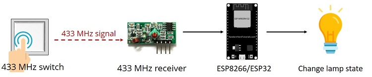
To control your ESP8266 or ESP32 with Amazon Echo, you need to install the FauxmoESP library. This library emulates a Belkin Wemo device, allowing you to control your ESP32 or ESP8266 using this protocol.This way, the Echo or Echo Dot instantly recognizes the device, after uploading the code, without any extra skills or third party services. You can read more about FauxmoESP here .
The FauxmoESP Installing the FauxmoESP Library Click here to download the FauxmoESP library . You should have a .zip folder in your Downloads Unzip the.zipfolder and you should getxoseperez-fauxmoesp-50cbcf3087fd folder Rename your folder fromtoxoseperez-fauxmoesp-50cbcf3087fd xoseperez_fauxmoesp Move the xoseperez_fauxmoesp folder to your Arduino IDE installationlibraries folder Finally, re-open your Arduino IDEFollow these next instructions if you’re using an ESP8266.
Alexa – Echo Dot with ESP8266 Installing the ESP8266 Board in Arduino IDE In order to upload code to your ESP8266 using Arduino IDE, you should install an add-on for the Arduino IDE that allows you to program the ESP8266 using the Arduino IDE and its programming language. If you haven’t installed the ESP8266 add-on for the Arduino IDE, follow the next tutorial: How to Install the ESP8266 Board in Arduino IDE .Installing the ESPAsyncTCP Library You also need to install theESPAsyncTCP Library library. Follow the next instructions to install it: Click here to download the ESPAsyncTCP library . You should have a .zip folder in your Downloads Unzip the.zipfolder and you should getESPAsyncTCP-master folder Rename your folder fromE toSPAsyncTCP-master ESPAsyncTCP Move the ESPAsyncTCP folder to your Arduino IDE installationlibraries folder Finally, re-open your Arduino IDESchematic
If you’re using an ESP8266 board, assemble your circuit by following the next schematic diagram – you can click the image to zoom.If you’re having trouble following the circuit diagram, you can use the following table as a reference:
 Alexa will respond to the following commands:
“Alexa, turn on lamp 1”
“Alexa, turn off lamp 1”
“Alexa, turn on lamp 2”
“Alexa, turn on lamp 2”
“Alexa, turn on lamps” turns on both lamps
“Alexa, turn off lamps” turns off both lamps
When you say something like “Alexa, turn on lamp 1”, the ESP8266 or ESP32 will trigger a relay to turn on lamp 1.
When you say something like“Alexa, turn off lamp 1”, the ESP8266 or ESP32 will send a signal to the relay to turn off the lamp.
This works similarly for lamp 2.
Alexa will respond to the following commands:
“Alexa, turn on lamp 1”
“Alexa, turn off lamp 1”
“Alexa, turn on lamp 2”
“Alexa, turn on lamp 2”
“Alexa, turn on lamps” turns on both lamps
“Alexa, turn off lamps” turns off both lamps
When you say something like “Alexa, turn on lamp 1”, the ESP8266 or ESP32 will trigger a relay to turn on lamp 1.
When you say something like“Alexa, turn off lamp 1”, the ESP8266 or ESP32 will send a signal to the relay to turn off the lamp.
This works similarly for lamp 2.

 ESP Board (you can use either ESP32 or ESP8266):
ESP8266 – read Best ESP8266 Wi-Fi Development Boards
ESP32 – we use the ESP32 DOIT DEVKIT V1 Board– 36 GPIOs (read ESP32 development boards comparison )
Alexa – Echo, Echo Show or Echo Dot
ESP Board (you can use either ESP32 or ESP8266):
ESP8266 – read Best ESP8266 Wi-Fi Development Boards
ESP32 – we use the ESP32 DOIT DEVKIT V1 Board– 36 GPIOs (read ESP32 development boards comparison )
Alexa – Echo, Echo Show or Echo Dot | ESP8266 | Connect to |
| GPIO 5 | 433 MHz receiver data pin |
| GPIO 4 | Relay IN1 pin |
| GPIO 14 | Relay IN2 pin |

Alexa – Echo Dot with ESP32
Follow these next instructions if you’re using an ESP32.
Schematic
If you’re using an ESP32 board, assemble your circuit by following the next schematic diagram – you can click the image to zoom. If you’re having trouble following the circuit diagram, you can use the following table as a reference:
| ESP32 | Connect to |
| GPIO 13 | 433 MHz receiver data pin |
| GPIO 14 | Relay IN1 pin |
| GPIO 12 | Relay IN2 pin |
Code
Copy the following code to your Arduino IDE, but don’t upload it yet! You need to make some changes to make it work for you.
/*
* Rui Santos
* Complete Project Details https://randomnerdtutorials.com
*/
#include <Arduino.h>
#ifdef ESP32
#include <WiFi.h>
#define RF_RECEIVER 13
#define RELAY_PIN_1 12
#define RELAY_PIN_2 14
#else
#include <ESP8266WiFi.h>
#define RF_RECEIVER 5
#define RELAY_PIN_1 4
#define RELAY_PIN_2 14
#endif
#include "fauxmoESP.h"
#include <RCSwitch.h>
#define SERIAL_BAUDRATE 115200
#define WIFI_SSID "REPLACE_WITH_YOUR_SSID"
#define WIFI_PASS "REPLACE_WITH_YOUR_PASSWORD"
#define LAMP_1 "lamp one"
#define LAMP_2 "lamp two"
fauxmoESP fauxmo;
RCSwitch mySwitch = RCSwitch();
// Wi-Fi Connection
void wifiSetup() {
// Set WIFI module to STA mode
WiFi.mode(WIFI_STA);
// Connect
Serial.printf("[WIFI] Connecting to %s ", WIFI_SSID);
WiFi.begin(WIFI_SSID, WIFI_PASS);
// Wait
while (WiFi.status() != WL_CONNECTED) {
Serial.print(".");
delay(100);
}
Serial.println();
// Connected!
Serial.printf("[WIFI] STATION Mode, SSID: %s, IP address: %s\n", WiFi.SSID().c_str(), WiFi.localIP().toString().c_str());
}
void setup() {
// Init serial port and clean garbage
Serial.begin(SERIAL_BAUDRATE);
Serial.println();
// Wi-Fi connection
wifiSetup();
// LED
pinMode(RELAY_PIN_1, OUTPUT);
digitalWrite(RELAY_PIN_1, HIGH);
pinMode(RELAY_PIN_2, OUTPUT);
digitalWrite(RELAY_PIN_2, HIGH);
mySwitch.enableReceive(RF_RECEIVER); // Receiver on interrupt 0 => that is pin #2
// By default, fauxmoESP creates it's own webserver on the defined port
// The TCP port must be 80 for gen3 devices (default is 1901)
// This has to be done before the call to enable()
fauxmo.createServer(true); // not needed, this is the default value
fauxmo.setPort(80); // This is required for gen3 devices
// You have to call enable(true) once you have a WiFi connection
// You can enable or disable the library at any moment
// Disabling it will prevent the devices from being discovered and switched
fauxmo.enable(true);
// You can use different ways to invoke alexa to modify the devices state:
// "Alexa, turn lamp two on"
// Add virtual devices
fauxmo.addDevice(LAMP_1);
fauxmo.addDevice(LAMP_2);
fauxmo.onSetState([](unsigned char device_id, const char * device_name, bool state, unsigned char value) {
// Callback when a command from Alexa is received.
// You can use device_id or device_name to choose the element to perform an action onto (relay, LED,...)
// State is a boolean (ON/OFF) and value a number from 0 to 255 (if you say "set kitchen light to 50%" you will receive a 128 here).
// Just remember not to delay too much here, this is a callback, exit as soon as possible.
// If you have to do something more involved here set a flag and process it in your main loop.
Serial.printf("[MAIN] Device #%d (%s) state: %s value: %d\n", device_id, device_name, state ? "ON" : "OFF", value);
if ( (strcmp(device_name, LAMP_1) == 0) ) {
// this just sets a variable that the main loop() does something about
Serial.println("RELAY 1 switched by Alexa");
//digitalWrite(RELAY_PIN_1, !digitalRead(RELAY_PIN_1));
if (state) {
digitalWrite(RELAY_PIN_1, LOW);
} else {
digitalWrite(RELAY_PIN_1, HIGH);
}
}
if ( (strcmp(device_name, LAMP_2) == 0) ) {
// this just sets a variable that the main loop() does something about
Serial.println("RELAY 2 switched by Alexa");
if (state) {
digitalWrite(RELAY_PIN_2, LOW);
} else {
digitalWrite(RELAY_PIN_2, HIGH);
}
}
});
}
void loop() {
// fauxmoESP uses an async TCP server but a sync UDP server
// Therefore, we have to manually poll for UDP packets
fauxmo.handle();
static unsigned long last = millis();
if (millis() - last > 5000) {
last = millis();
Serial.printf("[MAIN] Free heap: %d bytes\n", ESP.getFreeHeap());
}
if (mySwitch.available()) {
/*Serial.print("Received ");
Serial.print( mySwitch.getReceivedValue() );
Serial.print(" / ");
Serial.print( mySwitch.getReceivedBitlength() );
Serial.print("bit ");
Serial.print("Protocol: ");
Serial.println( mySwitch.getReceivedProtocol() );*/
if (mySwitch.getReceivedValue()==6819768) {
digitalWrite(RELAY_PIN_1, !digitalRead(RELAY_PIN_1));
}
if (mySwitch.getReceivedValue()==9463928) {
digitalWrite(RELAY_PIN_2, !digitalRead(RELAY_PIN_2));
}
delay(600);
mySwitch.resetAvailable();
}
}
View raw code
Selecting the right board
This code works both with ESP32 and ESP8266. To make it work for your board, you need to select the board you’re using in
Add your network credentials
You need to modify the following lines to include your network credentials. #define WIFI_SSID "Add your 433 MHz signal codes
You also need to include the signals you’ve decoded previously for your wall panel switches. Replace the value highlighted in red with the value you’ve gotten for the switch that controls lamp 1: if (mySwitch.getReceivedValue()==Uploading the code
After making all the necessary changes, you can upload code to your ESP. Make sure you have the right COM port selected, inAlexa, Discover Devices
With the circuit ready, and the code uploaded to your ESP8266 or ESP32, you need to ask alexa to discover devices.
Say: “Alexa, discover devices”.
It should answer as shown in the figure below.
 Alternatively, you can also discover devices using the Amazon Alexa app, by following the steps shown in the figure below.
 Then, ask Alexa to turn on/off the lamps.
You’ll also get information about the lamps state on the Serial Monitor.
Then, ask Alexa to turn on/off the lamps.
You’ll also get information about the lamps state on the Serial Monitor.
 After making sure everything is working properly, you can turn your circuit into a permanent solution.
Demonstration
For demonstration purposes, we’ve built our circuit in a prototyping stripboard, and attached everything in a wooden board, as shown in the figure below:
 Now you can ask Alexa to control your lamps with the following voice commands:
“Alexa, turn on lamp 1”
“Alexa, turn off lamp 1”
“Alexa, turn on lamp 2”
“Alexa, turn on lamp 2”
You can also control both lamps at the same time by creating a group in the Amazon Alexa app.
We called it “lamps”.
Now you can ask Alexa to control your lamps with the following voice commands:
“Alexa, turn on lamp 1”
“Alexa, turn off lamp 1”
“Alexa, turn on lamp 2”
“Alexa, turn on lamp 2”
You can also control both lamps at the same time by creating a group in the Amazon Alexa app.
We called it “lamps”.
 Now, you can control both lamps at the same time, using the following voice commands.
“Alexa, turn on lamps”
“Alexa, turn off lamps”
You can also physically control your lamps using the 433 MHz wall panel switches.
Now, you can control both lamps at the same time, using the following voice commands.
“Alexa, turn on lamps”
“Alexa, turn off lamps”
You can also physically control your lamps using the 433 MHz wall panel switches.

Wrapping Up
In this project we’ve shown how to control your ESP8266 and your ESP32 with voice commands using Amazon Echo.
As an example, we’ve controlled two 12V lamps using a relay.
Instead of 12V lamps, you can control any other electronics appliances.
We’ve also shown you how you can remotely control your lamps using a 433 MHz wall panel switch.
We hope you’ve found this project useful.
If you liked this post, you may also like:
Build a Home Automation System
Home Automation using ESP8266
Build an All-in-One ESP32 Weather Station Shield
ESP8266 Wi-Fi Button – DIY Amazon Dash Button Clone
ESP8266 Daily Task – Publish Temperature Readings to ThingSpeak
SMART HOME with Raspberry Pi, ESP32, ESP8266 [eBook]
Altimeter Datalogger: ESP32 with BMP388, MicroSD Card Storage and OLED Display
In this project, we’ll build an altimeter datalogger with the ESP32 and the BMP388 sensor. The BMP388 is a precise pressure sensor that allows us to estimate altitude with great accuracy. In this project, the pressure and altitude are logged to a file on a microSD. We’ve also added an OLED display to this project so that you can check the current altitude by pressing a pushbutton. For a getting started guide for the BMP388, check the following tutorial: ESP32 with BMP388 Barometric/Altimeter Sensor (Arduino IDE)
Project Overview
Before going straight to the project, let’s look at the main features of this project. The ESP32 sets an access point (
 The ESP32 is connected to a BMP388 pressure sensor, a microSD card module, an OLED display and a pushbutton.
Every minute (or other period of time you define in the code), the ESP32 records new sensor readings to a file on the microSD card (
The ESP32 is connected to a BMP388 pressure sensor, a microSD card module, an OLED display and a pushbutton.
Every minute (or other period of time you define in the code), the ESP32 records new sensor readings to a file on the microSD card (Parts Required
To build this project, you need the following parts: DOIT ESP32 DEVKIT V1 Board – read Best ESP32 Development Boards
BMP388 sensor module ( Guide for BMP388 )
MicroSD card module + microSD card
Pushbutton
10k Ohm resistor
Breadboard
Jumper wires
DOIT ESP32 DEVKIT V1 Board – read Best ESP32 Development Boards
BMP388 sensor module ( Guide for BMP388 )
MicroSD card module + microSD card
Pushbutton
10k Ohm resistor
Breadboard
Jumper wires
1.Install ESP32 Board in Arduino IDE
We’ll program the ESP32 using Arduino IDE. So, you must have the ESP32 add-on installed. Follow the next tutorial if you haven’t already: Installing ESP32 Board in Arduino IDE (Windows, Mac OS X, Linux) If you want to use VS Code with the PlatformIO extension, follow the next tutorial instead to learn how to program the ESP32: Getting Started with VS Code and PlatformIO IDE for ESP32 and ESP8266 (Windows, Mac OS X, Linux Ubuntu)2.Installing Libraries
To build this project, you need to install the following libraries: Adafruit BMP3XX library (Arduino Library Manager) Adafruit_Sensor library (Arduino Library Manager) Adafruit_SSD1306 library (Arduino Library Manager) Adafruit_GFX library (Arduino Library Manager) ESPAsyncWebServer (.zip folder); AsyncTCP (.zip folder). You can install the first four libraries using the Arduino Library Manager. Go toInstalling Libraries (VS Code + PlatformIO)
If you’re programming the ESP32 using PlatformIO, you should add the following lines to the platformio.ini file to include the libraries (also change the Serial Monitor speed to 115200): monitor_speed = 115200 lib_deps = ESP Async WebServer adafruit/Adafruit SSD1306@^2.4.6 adafruit/Adafruit GFX Library@^1.10.10 adafruit/Adafruit BMP3XX Library@^2.1.03.Formatting the MicroSD Card
Before proceeding with the tutorial, make sure you

Schematic Diagram
Connect all the components as shown in the following schematic diagram. You can also check the wiring in the following table:
| BMP388 | GPIO 21 (SDA), GPIO 22 (SCL) |
| OLED Display | GPIO 21 (SDA), GPIO 22 (SCL) |
| MicroSD card Module | GPIO 5 (CS), GPIO 23 (MOSI), GPIO 18 (CLK), GPIO 19 (MISO) |
| Pushbutton | GPIO 4 |
Code
Copy the following code to your ESP32 board, and the project will work straight away. /* Rui Santos Complete project details at https://RandomNerdTutorials.com/altimeter-datalogger-esp32-bmp388/ Permission is hereby granted, free of charge, to any person obtaining a copy of this software and associated documentation files. The above copyright notice and this permission notice shall be included in all copies or substantial portions of the Software. */ #include <Arduino.h> #include <Wire.h> #include <Adafruit_GFX.h> #include <Adafruit_SSD1306.h> #include <Adafruit_Sensor.h> #include "Adafruit_BMP3XX.h" #include <WiFi.h> #include <AsyncTCP.h> #include <ESPAsyncWebServer.h> //Libraries for microSD card #include "FS.h" #include "SD.h" #include "SPI.h" AsyncWebServer server(80); // Replace with your network credentials const char* ssid = "ESP32"; const char* password = NULL; //OLED Display #define SCREEN_WIDTH 128 // OLED display width, in pixels #define SCREEN_HEIGHT 64 // OLED display height, in pixels Adafruit_SSD1306 display(SCREEN_WIDTH, SCREEN_HEIGHT, &Wire, -1); // Variables for BMP388 float seaLevelPressure = 1013.25; Adafruit_BMP3XX bmp; float alt; float temp; float pres; String dataMessage; //Pushbutton const int buttonPin = 4; int buttonState; int lastButtonState = LOW; unsigned long lastDebounceTime = 0; unsigned long debounceDelay = 50; // the debounce time; increase if the output flickers //Timers for datalogging unsigned long lastTimer = 0; unsigned long timerDelay = 18000; const char* PARAM_INPUT_1 = "seaLevelPressure"; // HTML web page to handle 1 input field const char index_html[] PROGMEM = R"rawliteral( <!DOCTYPE HTML><html><head> <title>Sea Level Pressure</title> <meta name="viewport" content="width=device-width, initial-scale=1"> </head><body> <form action="/get"> Sea Level Pressure: <input type="float" name="seaLevelPressure"> <input type="submit" value="Submit"> </form> </body></html>)rawliteral"; void initBMP(){ if (!bmp.begin_I2C()) { // hardware I2C mode, can pass in address & alt Wire //if (! bmp.begin_SPI(BMP_CS)) { // hardware SPI mode //if (! bmp.begin_SPI(BMP_CS, BMP_SCK, BMP_MISO, BMP_MOSI)) { // software SPI mode Serial.println("Could not find a valid BMP3 sensor, check wiring!"); while (1); } // Set up oversampling and filter initialization bmp.setTemperatureOversampling(BMP3_OVERSAMPLING_8X); bmp.setPressureOversampling(BMP3_OVERSAMPLING_4X); bmp.setIIRFilterCoeff(BMP3_IIR_FILTER_COEFF_3); bmp.setOutputDataRate(BMP3_ODR_50_HZ); } void getReadings(){ if (! bmp.performReading()) { Serial.println("Failed to perform reading :("); return; } temp = bmp.temperature; pres = bmp.pressure / 100.0; alt = bmp.readAltitude(seaLevelPressure); } void initDisplay(){ if(!display.begin(SSD1306_SWITCHCAPVCC, 0x3C)) { Serial.println(F("SSD1306 allocation failed")); for(;;); } delay(500); display.clearDisplay(); display.setTextColor(WHITE); } void displayReadings(){ display.clearDisplay(); // display temperature display.setTextSize(1); display.setCursor(0,0); display.print("Temperature: "); display.setTextSize(2); display.setCursor(0,10); display.print(String(temp)); display.print(" "); display.setTextSize(1); display.cp437(true); display.write(167); display.setTextSize(2); display.print("C"); // display altitude display.setTextSize(1); display.setCursor(0, 35); display.print("Altitude: "); display.setTextSize(2); display.setCursor(0, 45); display.print(String(alt)); display.print(" m"); display.display(); } // Initialize SD card void initSDCard(){ if (!SD.begin()) { Serial.println("Card Mount Failed"); return; } } // Write to the SD card void writeFile(fs::FS &fs, const char * path, const char * message) { Serial.printf("Writing file: %s\n", path); File file = fs.open(path, FILE_WRITE); if(!file) { Serial.println("Failed to open file for writing"); return; } if(file.print(message)) { Serial.println("File written"); } else { Serial.println("Write failed"); } file.close(); } // Append data to the SD card void appendFile(fs::FS &fs, const char * path, const char * message) { Serial.printf("Appending to file: %s\n", path); File file = fs.open(path, FILE_APPEND); if(!file) { Serial.println("Failed to open file for appending"); return; } if(file.print(message)) { Serial.println("Message appended"); } else { Serial.println("Append failed"); } file.close(); } // Initialize WiFi void initWiFi() { WiFi.softAP(ssid, password); IPAddress IP = WiFi.softAPIP(); Serial.print("AP IP address: "); Serial.println(IP); } void setup() { Serial.begin(115200); initBMP(); initDisplay(); initSDCard(); initWiFi(); pinMode(buttonPin, INPUT); File file = SD.open("/data.txt"); if(!file) { Serial.println("File doesn't exist"); Serial.println("Creating file..."); writeFile(SD, "/data.txt", "Pressure, Altitude, Temperature \r\n"); } else { Serial.println("File already exists"); } file.close(); // Send web page with input fields to client server.on("/", HTTP_GET, [](AsyncWebServerRequest *request){ request->send_P(200, "text/html", index_html); }); // Send a GET request to <ESP_IP>/get?input1=<inputMessage> server.on("/get", HTTP_GET, [] (AsyncWebServerRequest *request) { String inputMessage; // GET input1 value on <ESP_IP>/get?input1=<inputMessage> if (request->hasParam(PARAM_INPUT_1)) { inputMessage = request->getParam(PARAM_INPUT_1)->value(); seaLevelPressure = inputMessage.toFloat(); } else { inputMessage = "No message sent"; } Serial.println(inputMessage); request->send(200, "text/html", "HTTP GET request sent to your ESP on input field with value: " + inputMessage + "<br><a href=\"/\">Return to Home Page</a>"); }); server.begin(); } void loop() { int reading = digitalRead(buttonPin); display.clearDisplay(); // Light up when the pushbutton is pressed if (reading != lastButtonState) { lastDebounceTime = millis(); } if ((millis() - lastDebounceTime) > debounceDelay) { if (reading != buttonState) { buttonState = reading; if (buttonState == HIGH) { getReadings(); displayReadings(); delay(5000); display.clearDisplay(); display.display(); lastDebounceTime = millis(); } } } lastButtonState = reading; // Log data every timerDelay seconds if ((millis() - lastTimer) > timerDelay) { //Concatenate all info separated by commas getReadings(); dataMessage = String(pres) + "," + String(alt) + "," + String(temp)+ "," + String(seaLevelPressure) + "\r\n"; Serial.print(dataMessage); //Append the data to file appendFile(SD, "/data.txt", dataMessage.c_str()); lastTimer = millis(); } } View raw codeHow the Code Works
Continue reading to learn how the code works, or skip to the .
Start by including all the necessary libraries:
#include <Arduino.h>
#include <Wire.h>
#include <Adafruit_GFX.h>
#include <Adafruit_SSD1306.h>
#include <Adafruit_Sensor.h>
#include "Adafruit_BMP3XX.h"
#include <WiFi.h>
#include <AsyncTCP.h>
#include <ESPAsyncWebServer.h>
//Libraries for microSD card
#include "FS.h"
#include "SD.h"
#include "SPI.h"
The following lines set the name and password for the access point.
In this case, we set the password to NULL—this creates an open access point.
You can add a password for the access point if you want.
// Replace with your network credentials
const char* ssid = "ESP32";
const char* password = NULL;
Set the OLED display size and instantiate an instance on the default I2C pins.
// OLED Display
#define SCREEN_WIDTH 128 // OLED display width, in pixels
#define SCREEN_HEIGHT 64 // OLED display height, in pixels
Adafruit_SSD1306 display(SCREEN_WIDTH, SCREEN_HEIGHT, &Wire, -1);
We set the default sea level pressure as 1013.25 hPa.
However, you should connect to the access point to change this value for more accurate results.
float seaLevelPressure = 1013.25;
Create an instance for the BMP388 sensor called bmp—this automatically uses the default I2C pins.
Adafruit_BMP3XX bmp;
The following variables will be used to save the sensor data.
float alt;
float temp;
float pres;
String dataMessage;
The pushbutton is connected to GPIO 4.
const int buttonPin = 4;
The buttonState and lastButtonState variables save the current button state and the last button state.
int buttonState;
int lastButtonState = LOW;
The next variables are used to debounce the pushbutton.
unsigned long lastDebounceTime = 0;
unsigned long debounceDelay = 50; // the debounce time; increase if the output flickers
The BMP388 readings are saved every minute.
You can change that in the timerDelay variable (in milliseconds).
//Timers for datalogging
unsigned long lastTimer = 0;
unsigned long timerDelay = 60000;
The PARAM_INPUT_1 variable will be used to search for the input value on the HTML form.
const char* PARAM_INPUT_1 = "seaLevelPressure";
The index_html variable saves a simple HTML page that displays an input field to enter the current sea level pressure.
// HTML web page to handle 1 input field
const char index_html[] PROGMEM = R"rawliteral(
<!DOCTYPE HTML><html><head>
<title>Sea Level Pressure</title>
<meta name="viewport" content="width=device-width, initial-scale=1">
</head><body>
<form action="/get">
Sea Level Pressure: <input type="float" name="seaLevelPressure">
<input type="submit" value="Submit">
</form>
</body></html>)rawliteral";
When you submit a new pressure value, the ESP32 receives a request on the following URL (for example, pressure = 1022):
/get?seaLevelPressure=1022
Initialize BMP388
The initBMP() function initializes the BMP388 sensor. Read the ESP32 with the BMP388 tutorial to learn more. void initBMP(){ if (!bmp.begin_I2C()) { // hardware I2C mode, can pass in address & alt Wire //if (! bmp.begin_SPI(BMP_CS)) { // hardware SPI mode //if (! bmp.begin_SPI(BMP_CS, BMP_SCK, BMP_MISO, BMP_MOSI)) { // software SPI mode Serial.println("Could not find a valid BMP3 sensor, check wiring!"); while (1); } // Set up oversampling and filter initialization bmp.setTemperatureOversampling(BMP3_OVERSAMPLING_8X); bmp.setPressureOversampling(BMP3_OVERSAMPLING_4X); bmp.setIIRFilterCoeff(BMP3_IIR_FILTER_COEFF_3); bmp.setOutputDataRate(BMP3_ODR_50_HZ); }Get BMP388 Readings
The getReadings() function gets new readings: temperature, pressure, and altitude and saves them on the temp, pres, and alt variables. void getReadings(){ if (! bmp.performReading()) { Serial.println("Failed to perform reading :("); return; } temp = bmp.temperature; pres = bmp.pressure / 100.0; alt = bmp.readAltitude(seaLevelPressure); }Initialize OLED Display
The initDisplay() function initializes the OLED display. void initDisplay(){ if(!display.begin(SSD1306_SWITCHCAPVCC, 0x3C)) { Serial.println(F("SSD1306 allocation failed")); for(;;); } delay(500); display.clearDisplay(); display.setTextColor(WHITE); }Display BMP388 Readings
The displayReadings() function displays the temperature and altitude on the display. void displayReadings(){ display.clearDisplay(); // display temperature display.setTextSize(1); display.setCursor(0,0); display.print("Temperature: "); display.setTextSize(2); display.setCursor(0,10); display.print(String(temp)); display.print(" "); display.setTextSize(1); display.cp437(true); display.write(167); display.setTextSize(2); display.print("C"); // display altitude display.setTextSize(1); display.setCursor(0, 35); display.print("Altitude: "); display.setTextSize(2); display.setCursor(0, 45); display.print(String(alt)); display.print(" m"); display.display(); }Initialize microSD card
The initSDCard() function initializes the microSD card on the default SPI pins. // Initialize SD card void initSDCard(){ if (!SD.begin()) { Serial.println("Card Mount Failed"); return; } } If you want to use other pins, read this article to learn how to set custom SPI pins .Write to the microSD card
The writeFile() and appendFile() functions write and append a message to a file on the microSD card. // Write to the SD card void writeFile(fs::FS &fs, const char * path, const char * message) { Serial.printf("Writing file: %s\n", path); File file = fs.open(path, FILE_WRITE); if(!file) { Serial.println("Failed to open file for writing"); return; } if(file.print(message)) { Serial.println("File written"); } else { Serial.println("Write failed"); } file.close(); } // Append data to the SD card void appendFile(fs::FS &fs, const char * path, const char * message) { Serial.printf("Appending to file: %s\n", path); File file = fs.open(path, FILE_APPEND); if(!file) { Serial.println("Failed to open file for appending"); return; } if(file.print(message)) { Serial.println("Message appended"); } else { Serial.println("Append failed"); } file.close(); }Set Access Point
Initialize Wi-Fi by setting the ESP32 as an access point. // Initialize WiFi void initWiFi() { WiFi.softAP(ssid, password); IPAddress IP = WiFi.softAPIP(); Serial.print("AP IP address: "); Serial.println(IP); }setup()
In the setup(), initialize the Serial Monitor, the BMP388 sensor, the OLED display, the microSD card, start the access point and define the pushbutton as an INPUT. Serial.begin(115200); initBMP(); initDisplay(); initSDCard(); initWiFi(); pinMode(buttonPin, INPUT); Create a new file on the microSD card called data.txt if it doesn’t exist already. File file = SD.open("/data.txt"); if(!file) { Serial.println("File doesn't exist"); Serial.println("Creating file..."); writeFile(SD, "/data.txt", "Pressure, Altitude, Temperature \r\n"); } else { Serial.println("File already exists"); } file.close(); When you access the Access Point on the root (/) URL, the server (ESP32) sends the HTML page (index_html variable) with the form. // Send web page with input fields to client server.on("/", HTTP_GET, [](AsyncWebServerRequest *request){ request->send_P(200, "text/html", index_html); }); The following part gets the input field you’ve inserted in the form and saves it in the seaLevelPressure variable. // Send web page with input fields to client server.on("/", HTTP_GET, [](AsyncWebServerRequest *request){ request->send_P(200, "text/html", index_html); }); // Send a GET request to <ESP_IP>/get?input1=<inputMessage> server.on("/get", HTTP_GET, [] (AsyncWebServerRequest *request) { String inputMessage; // GET input1 value on <ESP_IP>/get?input1=<inputMessage> if (request->hasParam(PARAM_INPUT_1)) { inputMessage = request->getParam(PARAM_INPUT_1)->value(); seaLevelPressure = inputMessage.toFloat(); } else { inputMessage = "No message sent"; } Serial.println(inputMessage); request->send(200, "text/html", "HTTP GET request sent to your ESP on input field with value: " + inputMessage + "<br><a href=\"/\">Return to Home Page</a>"); });loop()
In the loop() is where we check the state of the pushbutton. If it was pressed, we light up the OLED display with the current temperature and altitude readings. int reading = digitalRead(buttonPin); display.clearDisplay(); // Light up when the pushbutton is pressed if (reading != lastButtonState) { lastDebounceTime = millis(); } if ((millis() - lastDebounceTime) > debounceDelay) { if (reading != buttonState) { buttonState = reading; if (buttonState == HIGH) { getReadings(); displayReadings(); delay(5000); display.clearDisplay(); display.display(); lastDebounceTime = millis(); } } } lastButtonState = reading; We also save new readings every 60 seconds (timerDelay) variable. if ((millis() - lastTimer) > timerDelay) { //Concatenate all info separated by commas getReadings(); dataMessage = String(pres) + "," + String(alt) + "," + String(temp)+ "," + String(seaLevelPressure) + "\r\n"; Serial.print(dataMessage); //Append the data to file appendFile(SD, "/data.txt", dataMessage.c_str()); lastTimer = millis(); }Demonstration
Upload the code to your board. Don’t forget to select the right board (ESP32) and COM port. After uploading, you should get the following messages on the Serial Monitor*. *In my case, it shows “File already exists”.
But, when you’re running it for the first time, it should show “File doesn’t exist”, “Creating file …”.
After a few seconds, it will display the first readings.
After that, if you want to get more accurate altitude readings, on your computer or smartphone, connect to the ESP32 access point.
Open a browser and go to the 192.168.4.1 IP address and insert the current sea level pressure at your location.
After you’ve clicked the submit button, you’ll see the inserted value on the Serial Monitor.
*In my case, it shows “File already exists”.
But, when you’re running it for the first time, it should show “File doesn’t exist”, “Creating file …”.
After a few seconds, it will display the first readings.
After that, if you want to get more accurate altitude readings, on your computer or smartphone, connect to the ESP32 access point.
Open a browser and go to the 192.168.4.1 IP address and insert the current sea level pressure at your location.
After you’ve clicked the submit button, you’ll see the inserted value on the Serial Monitor.
 If you click on the pushbutton, you can check the current temperature and altitude on the OLED display.
 If you want to check all the readings, you just need to connect the microSD card to your computer, and you can access the data.txt file with all the records.
To analyze your data, you can use Google Sheets, Excel, or other software.
If you want to check all the readings, you just need to connect the microSD card to your computer, and you can access the data.txt file with all the records.
To analyze your data, you can use Google Sheets, Excel, or other software.
Why we created this project?
Some curiosities about this project for those of you that like to know a little more about us. A few weeks ago, we visited Pico Island, a Portuguese island in the Azores archipelago. The landscape features a volcano, Ponta do Pico, the highest mountain in Portugal, and the Mid-Atlantic Ridge’s highest elevation with 2351 meters. One of the highlights of visiting Pico Island is climbing/hiking the mountain to the highest point. We decided that this trip would be a good opportunity to test the BMP388 sensor at varying altitudes—so, we created this datalogging project.

 At the top, the sensor was marking approximately 2260 meters, which is approximately 90 meters from the real value (2351 meters).
I don’t think that a difference of 90 meters is relevant at such an altitude.
What do you think? The temperature was marking 13oC (55oF), which was the same temperature predicted in the forecast.
We tried to take pictures of the OLED display showing the results using our smartphone.
Unfortunately, due to the frame rate of the OLED display, the numbers are not visible.
At the top, the sensor was marking approximately 2260 meters, which is approximately 90 meters from the real value (2351 meters).
I don’t think that a difference of 90 meters is relevant at such an altitude.
What do you think? The temperature was marking 13oC (55oF), which was the same temperature predicted in the forecast.
We tried to take pictures of the OLED display showing the results using our smartphone.
Unfortunately, due to the frame rate of the OLED display, the numbers are not visible.
 Have you visited Pico Island or the Azores? Let us know in the comments below.
Build an All-in-One ESP32 Weather Station Shield
In this project I’ll show you how you can build an all-in-one ESP32 weather station shield and display the sensor readings on a web server. The web server displays data from all the sensors and automatically updates the readings every ten seconds, without the need to refresh the web page.Watch the Video Tutorial and Project Demo
This guide is available in video format (watch below) and in written format (continue reading).
JLCPCB
The previous video was sponsored by JLCPCB . JLCPCB is a well known PCB prototype company in China. It is specialized in quick PCB prototype and small-batch production. You can order a minimum of 10 PCBs for just $2. If you want to turn your breadboard circuits into real boards and make your projects look more professional, you just have to upload the Gerber files to order high quality PCBs for low prices.
We’ll show you how to do this later in this blog post.
If you want to turn your breadboard circuits into real boards and make your projects look more professional, you just have to upload the Gerber files to order high quality PCBs for low prices.
We’ll show you how to do this later in this blog post.
Resources
You can find all the resources needed to build this project in the bullets below.
Web server code (for Arduino IDE)
HTML page
Schematic diagram
Gerber files
KiCad project to edit the PCB
ESP32 Weather Station Shield Features
To build this project, I’ve designed a PCB for the ESP32 DEVKIT V1 DOIT board.
The PCB I’ve built only works with the version with 30 GPIOs.
 I’ve designed the shield to be a compact weather station.
The PCB has a lot of features so that it can suit a lot of different projects for different applications.
In fact, I didn’t use all the PCB features in this project.
Additionally, this shield can also be used as a learning shield as it comes with some of the most used components when starting to learn how to program the ESP32.
I’ve designed the shield to be a compact weather station.
The PCB has a lot of features so that it can suit a lot of different projects for different applications.
In fact, I didn’t use all the PCB features in this project.
Additionally, this shield can also be used as a learning shield as it comes with some of the most used components when starting to learn how to program the ESP32.
 The shield allows you to control:
2x SMD LEDs
1x Pushbutton
1x Trimpot
1x DHT22 temperature and humidity sensor
1x BMP180 barometric sensor
1x Light dependent resistor
1x MicroSD card module
2x Terminal blocks –that give you access to 3 GPIOs to connect other components
The microSD card module is a very interesting addition to the shield: it can be used to store readings if you want to build a data logger, or it can store an HTML file to serve a web page – as we’ll do in this project.
I think this is a better and easier way to build a web server that requires more complex web pages.
The shield allows you to control:
2x SMD LEDs
1x Pushbutton
1x Trimpot
1x DHT22 temperature and humidity sensor
1x BMP180 barometric sensor
1x Light dependent resistor
1x MicroSD card module
2x Terminal blocks –that give you access to 3 GPIOs to connect other components
The microSD card module is a very interesting addition to the shield: it can be used to store readings if you want to build a data logger, or it can store an HTML file to serve a web page – as we’ll do in this project.
I think this is a better and easier way to build a web server that requires more complex web pages.
ESP32 Shield Pin Assignment
The following table describes the pin assignment for each component on the shield:
| Pushbutton | GPIO 33 |
| Trimpot | GPIO 32 |
| Photoresistor (LDR) | GPIO 4 |
| DHT22 data pin | GPIO 15 |
| LED1 | GPIO 27 |
| LED2 | GPIO 26 |
| BMP180 | SDA(GPIO 21); SCL(GPIO 22) |
| SD card module | MOSI(GPIO 23); MISO(GPIO 19): CLK(GPIO 18); CS(GPIO 5) |
| Free GPIOs (terminal blocks) | GPIO14, GPIO13, GPIO12 |
Testing the Circuit on a Breadboard
Before designing the shield, I’ve assembled the circuit on a breadboard.
If you don’t want to make a PCB, you can still follow this project by assembling the circuit on a breadboard.
Parts Required
To assemble the circuit on a breadboard you need the following parts: (read ESP32 development boards comparison ) 2x 5mm LED 2x 330 Ohm resistor 1x Pushbutton 1x 10k Ohm resistor 1x 10k Ohm potentiometer 1x DHT22 temperature and humidity sensor 1x BMP180 1x MicroSD card module Breadboard Jumper wires
Schematic
After gathering all the needed parts, you can assemble the circuit by following the next schematic diagram: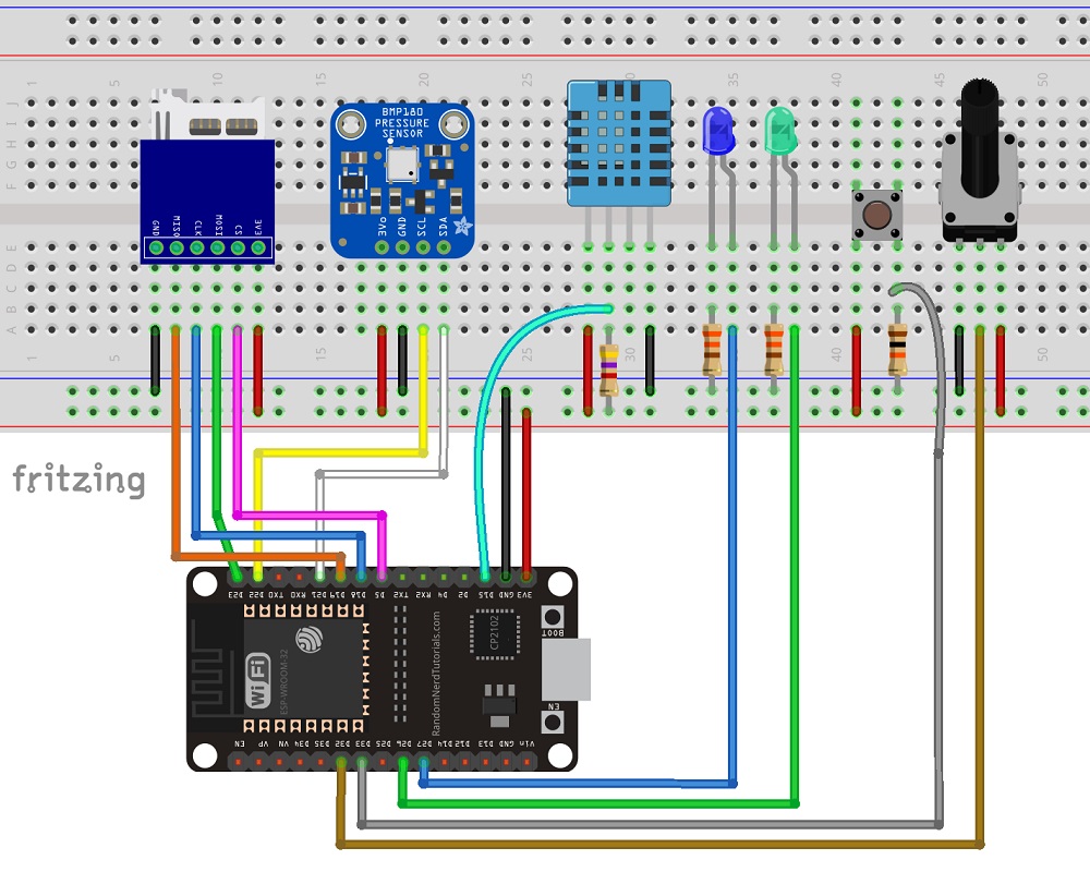

Designing the PCB
After making sure the circuit was working properly, I’ve designed the PCB version on KiCad .
KiCad is an open-source software used to design PCBs.
I won’t explore how I’ve designed the PCB, but I provide all the files if you want to modify the PCB for yourself.
Click here to download the KiCad project files.

Ordering the PCBs
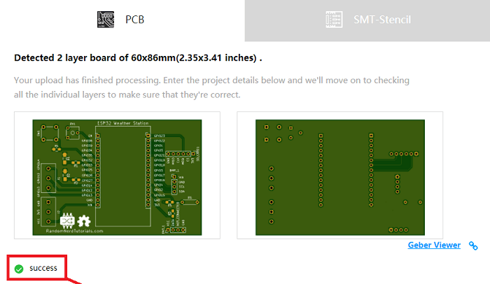
You don’t need to know how to design the PCB to order one. You just have to: 1. To download the Gerber files, click here to download the .zip file . 2. Go to JLCPCB.com , click the “ 3.
You’ll see a success message at the bottom.
Then, you can use the “Gerber Viewer” link at the bottom right corner to check if everything went as expected.
You can view the top and bottom of the PCB.
You can view or hide the solder-mask, silkscreen, copper, etc.
3.
You’ll see a success message at the bottom.
Then, you can use the “Gerber Viewer” link at the bottom right corner to check if everything went as expected.
You can view the top and bottom of the PCB.
You can view or hide the solder-mask, silkscreen, copper, etc.
 With the default settings, you can order 10 PCBs for just $2.
However, if you want to select other settings like a different PCB Color it will cost you a few more dollars.
When, you’re happy with your order.
Click the “
With the default settings, you can order 10 PCBs for just $2.
However, if you want to select other settings like a different PCB Color it will cost you a few more dollars.
When, you’re happy with your order.
Click the “ My PCBs took 1 day to be manufactured and they arrived in 5 business days using DHL delivery option.
Unboxing
After a week, I received my PCBs at my office.
Everything came well packed, and I also received a pen from JLCPCB.
 Taking a closer look at the PCBs, I must say that I’m really impressed with the quality.
I don’t think you can get a better PCB service for this price.
Taking a closer look at the PCBs, I must say that I’m really impressed with the quality.
I don’t think you can get a better PCB service for this price.

Soldering the Components
The next step was soldering the components to the PCB.
I used SMD LEDs and SMD resistors.
I know it’s a bit difficult to solder SMD components, but they can save a lot of space on the PCB.
I’ve solder header pins to attach the ESP32, and the sensors.
This way, I can easily replace the sensors, if needed.
 Here’s a list of all the components you need to solder on the PCB:
2x SMD LEDs
2x 330 Ohm SMD resistors
1x 10k Ohm SMD resistor
1x 4.7k Ohm SMD resistor
1x Trimpot (10k)
1x Pushbutton
1x SD card module
1x BMP180 barometric sensor
1x DHT22 temperature and humidity sensor
2x Screw terminal blocks
Female pin header socket
ESP32 DOIT DEVKIT V1 Board (version with 30 GPIOs) – you can get this board from Banggood , or
The following figure shows how the PCB looks like after soldering all the components.
Here’s a list of all the components you need to solder on the PCB:
2x SMD LEDs
2x 330 Ohm SMD resistors
1x 10k Ohm SMD resistor
1x 4.7k Ohm SMD resistor
1x Trimpot (10k)
1x Pushbutton
1x SD card module
1x BMP180 barometric sensor
1x DHT22 temperature and humidity sensor
2x Screw terminal blocks
Female pin header socket
ESP32 DOIT DEVKIT V1 Board (version with 30 GPIOs) – you can get this board from Banggood , or
The following figure shows how the PCB looks like after soldering all the components.

Preparing the ESP32 board in Arduino IDE
In order to upload code to your ESP32 using Arduino IDE, you should install an add-on for the Arduino IDE that allows you to program the ESP32 using the Arduino IDE and its programming language.
Follow the next tutorial to prepare your Arduino IDE:
Code
The next step is writing the code to read the sensors and build the web server.
The code for this project is divided into two parts:
The code in Arduino IDE to read the sensors and host a web server
An HTML file to build the web page.
This HTML file should be saved in the microSD card.
Copy the code provided to the Arduino IDE.
The code for this project is a bit long, but it’s fairly easy to understand.
I’ve also added various comments along the code.
Don’t upload the code yet.
/*
* Rui Santos
* Complete Project Details https://randomnerdtutorials.com
*/
// Load required libraries
#include <WiFi.h>
#include "SD.h"
#include "DHT.h"
#include <Wire.h>
#include <Adafruit_BMP085.h>
// Replace with your network credentials
const char* ssid = "REPLACE_WITH_YOUR_SSID";
const char* password = "REPLACE_WITH_YOUR_PASSWORD";
// uncomment one of the lines below for whatever DHT sensor type you're using
//#define DHTTYPE DHT11 // DHT 11
//#define DHTTYPE DHT21 // DHT 21 (AM2301)
#define DHTTYPE DHT22 // DHT 22 (AM2302), AM2321
// GPIO the DHT is connected to
const int DHTPin = 15;
//intialize DHT sensor
DHT dht(DHTPin, DHTTYPE);
// create a bmp object
Adafruit_BMP085 bmp;
// Web page file stored on the SD card
File webFile;
// Set potentiometer GPIO
const int potPin = 32;
// IMPORTANT: At the moment, GPIO 4 doesn't work as an ADC when using the Wi-Fi library
// This is a limitation of this shield, but you can use another GPIO to get the LDR readings
const int LDRPin = 4;
// variables to store temperature and humidity
float tempC;
float tempF;
float humi;
// Variable to store the HTTP request
String header;
// Set web server port number to 80
WiFiServer server(80);
void setup(){
// initialize serial port
Serial.begin(115200);
// initialize DHT sensor
dht.begin();
// initialize BMP180 sensor
if (!bmp.begin()){
Serial.println("Could not find BMP180 or BMP085 sensor");
while (1) {}
}
// initialize SD card
if(!SD.begin()){
Serial.println("Card Mount Failed");
return;
}
uint8_t cardType = SD.cardType();
if(cardType == CARD_NONE){
Serial.println("No SD card attached");
return;
}
// initialize SD card
Serial.println("Initializing SD card...");
if (!SD.begin()) {
Serial.println("ERROR - SD card initialization failed!");
return; // init failed
}
// Connect to Wi-Fi network with SSID and password
Serial.print("Connecting to ");
Serial.println(ssid);
WiFi.begin(ssid, password);
while (WiFi.status() != WL_CONNECTED) {
delay(500);
Serial.print(".");
}
// Print local IP address and start web server
Serial.println("");
Serial.println("WiFi connected.");
Serial.println("IP address: ");
Serial.println(WiFi.localIP());
server.begin();
}
void loop(){
WiFiClient client = server.available(); // Listen for incoming clients
if (client) { // if new client connects
boolean currentLineIsBlank = true;
while (client.connected()) {
if (client.available()) { // client data available to read
char c = client.read(); // read 1 byte (character) from client
header += c;
// if the current line is blank, you got two newline characters in a row.
// that's the end of the client HTTP request, so send a response:
if (c == '\n' && currentLineIsBlank) {
// send a standard http response header
client.println("HTTP/1.1 200 OK");
// Send XML file or Web page
// If client already on the web page, browser requests with AJAX the latest
// sensor readings (ESP32 sends the XML file)
if (header.indexOf("update_readings") >= 0) {
// send rest of HTTP header
client.println("Content-Type: text/xml");
client.println("Connection: keep-alive");
client.println();
// Send XML file with sensor readings
sendXMLFile(client);
}
// When the client connects for the first time, send it the index.html file
// stored in the microSD card
else {
// send rest of HTTP header
client.println("Content-Type: text/html");
client.println("Connection: keep-alive");
client.println();
// send web page stored in microSD card
webFile = SD.open("/index.html");
if (webFile) {
while(webFile.available()) {
// send web page to client
client.write(webFile.read());
}
webFile.close();
}
}
break;
}
// every line of text received from the client ends with \r\n
if (c == '\n') {
// last character on line of received text
// starting new line with next character read
currentLineIsBlank = true;
}
else if (c != '\r') {
// a text character was received from client
currentLineIsBlank = false;
}
} // end if (client.available())
} // end while (client.connected())
// Clear the header variable
header = "";
// Close the connection
client.stop();
Serial.println("Client disconnected.");
} // end if (client)
}
// Send XML file with the latest sensor readings
void sendXMLFile(WiFiClient cl){
// Read DHT sensor and update variables
readDHT();
// Prepare XML file
cl.print("<?xml version = \"1.0\" ?>");
cl.print("<inputs>");
cl.print("<reading>");
cl.print(tempC);
cl.println("</reading>");
cl.print("<reading>");
cl.print(tempF);
cl.println("</reading>");
cl.print("<reading>");
cl.print(humi);
cl.println("</reading>");
float currentTemperatureC = bmp.readTemperature();
cl.print("<reading>");
cl.print(currentTemperatureC);
cl.println("</reading>");
float currentTemperatureF = (9.0/5.0)*currentTemperatureC+32.0;
cl.print("<reading>");
cl.print(currentTemperatureF);
cl.println("</reading>");
cl.print("<reading>");
cl.print(bmp.readPressure());
cl.println("</reading>");
cl.print("<reading>");
cl.print(analogRead(potPin));
cl.println("</reading>");
// IMPORTANT: Read the note about GPIO 4 at the pin assignment
cl.print("<reading>");
cl.print(analogRead(LDRPin));
cl.println("</reading>");
cl.print("</inputs>");
}
void readDHT(){
// Sensor readings may also be up to 2 seconds 'old' (its a very slow sensor)
humi = dht.readHumidity();
// Read temperature as Celsius (the default)
tempC = dht.readTemperature();
// Read temperature as Fahrenheit (isFahrenheit = true)
tempF = dht.readTemperature(true);
// Check if any reads failed and exit early (to try again).
if (isnan(humi) || isnan(tempC) || isnan(tempF)) {
Serial.println("Failed to read from DHT sensor!");
return;
}
/*Serial.print("Humidity: ");
Serial.print(humi);
Serial.print(" %\t Temperature: ");
Serial.print(tempC);
Serial.print(" *C ");
Serial.print(tempF);
Serial.println(" *F");*/
}
View raw code
Before uploading the code, you need to modify the following lines to add your SSID and password.
// Replace with your network credentials
const char* ssid = " Now, everything should be ready.
Testing the ESP32 Weather Station Shield Web Server
Open the serial monitor at a baud rate of 115200, and check the ESP32 IP address.
 By the end of the project, you have your own ESP32 weather station web server, and all the hardware is well compacted on a PCB.
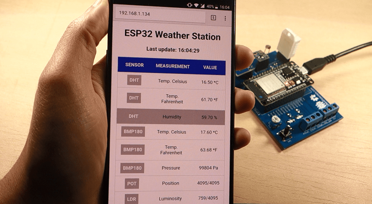
Open your browser, type the IP address and you should see a table with the latest sensor readings.
The web server displays the DHT22, BMP180, potentiometer and LDR readings.
The readings are updated every 10 seconds without the need to refresh the web page.
By the end of the project, you have your own ESP32 weather station web server, and all the hardware is well compacted on a PCB.
Open your browser, type the IP address and you should see a table with the latest sensor readings.
The web server displays the DHT22, BMP180, potentiometer and LDR readings.
The readings are updated every 10 seconds without the need to refresh the web page.
 To update the readings without refreshing the web page, we use AJAX.
As you can read here , AJAX is a developer’s dream, because it can update the web page without reloading the page, request and receive data from a server, after the page has loaded, and send data to a server in the background.
To update the readings without refreshing the web page, we use AJAX.
As you can read here , AJAX is a developer’s dream, because it can update the web page without reloading the page, request and receive data from a server, after the page has loaded, and send data to a server in the background.

Taking it Further
There’s still room to improve this project, you can use the extra terminals to connect other sensors or a relay.
You can also program the ESP32 to trigger an event when a reading is below or above a certain threshold.
The idea is that you modify the code provided to use the shield in a way that meets your own specific needs.
If you want to get your own all-in-one ESP32 weather station shield, you just need to upload the .zip file with the Gerber files to the JLCPCB website.
You’ll get high quality PCBs for a very reasonable price.
Wrapping Up
I’m giving away 3 bare PCBs to someone that posts a comment below! DIY Cloud Weather Station with ESP32/ESP8266 (MySQL Database and PHP)
Build a cloud weather station dashboard to visualize your ESP32 or ESP8266 sensor readings from anywhere in the world. You’ll visualize your sensor data displayed on gauges and on a table. The ESP32 or ESP8266 will make an HTTP POST request to a PHP script to insert your data into a MySQL database. Updated on 27 March 2023
Previously, we’ve stored sensor readings in a database and displayed them on a table or charts that you can access from anywhere using your own server.
Now, I’ve decided to take a few steps further and add some more information to the web page.
I’ve added two gauges to display the latest temperature and humidity readings as well as some statistics about the minimum, maximum and average readings from a number of readings that you can define.
You can also visualize all the latest readings on a table and you can select how many readings you want to show.
To build this project, you’ll use these technologies:
ESP32 or ESP8266 programmed with Arduino IDE
Hosting server and domain name
PHP script to insert data into MySQL and display it on a web page
MySQL database to store readings
This project is divided into the following main sections:
Updated on 27 March 2023
Previously, we’ve stored sensor readings in a database and displayed them on a table or charts that you can access from anywhere using your own server.
Now, I’ve decided to take a few steps further and add some more information to the web page.
I’ve added two gauges to display the latest temperature and humidity readings as well as some statistics about the minimum, maximum and average readings from a number of readings that you can define.
You can also visualize all the latest readings on a table and you can select how many readings you want to show.
To build this project, you’ll use these technologies:
ESP32 or ESP8266 programmed with Arduino IDE
Hosting server and domain name
PHP script to insert data into MySQL and display it on a web page
MySQL database to store readings
This project is divided into the following main sections:
Watch the Video Demonstration
To see how the project works, you can watch the following video demonstration:
0.
Download Source Code
For this project, you’ll need these files:
SQL query to create your table: SensorData_Table.sql
Insert and access database readings: esp-database.php
Handle HTTP Post requests: esp-post-data.php
CSS file to style your web page: esp-style.css
Display your sensor readings: esp-weather-station.php
Arduino Sketch for 1.Hosting Your PHP Application and MySQL Database
The goal of this project is to have your own domain name and hosting account that allows you to store sensor readings from the ESP32 or ESP8266. You can visualize the readings from anywhere in the world by accessing your own server domain. Here’s a high-level overview of how the project works: You have an ESP32 or ESP8266 that sends sensor readings to your own server.
For this, you have your board connected to your router;
In your server, there’s a PHP script that allows you to store your readings in a MySQL database;
Then, another PHP script will display the web page with the gauges, table, and all the other information;
Finally, you can visualize the readings from anywhere in the world by accessing your own domain name.
You have an ESP32 or ESP8266 that sends sensor readings to your own server.
For this, you have your board connected to your router;
In your server, there’s a PHP script that allows you to store your readings in a MySQL database;
Then, another PHP script will display the web page with the gauges, table, and all the other information;
Finally, you can visualize the readings from anywhere in the world by accessing your own domain name.
Hosting Services
I recommend using one of the following hosting services that can handle all the project requirements: Bluehost (user-friendly with cPanel) : free domain name when you sign up for the 3-year plan. I recommend choosing the unlimited websites option; Digital Ocean : Linux server that you manage through a command line. I only recommended this option for advanced users. Those two services are the ones that I use and personally recommend, but you can use any other hosting service. Any hosting service that offers PHP and MySQL will work with this tutorial. If you don’t have a hosting account, I recommend signing up for Bluehost . Get Hosting and Domain Name with Bluehost When buying a hosting account, you’ll also have to purchase a domain name. This is what makes this project interesting: you’ll be able to go to your domain name (https://example.com) and see your ESP readings. If you like our projects, you might consider signing up for one of the recommended hosting services, because you’ll be supporting our work.2.Preparing Your MySQL Database
After signing up for a hosting account and setting up a domain name , you can login to your cPanel or similar dashboard. After that, follow the next steps to create your database, username, password, and SQL table.Creating a database and user
Open the “


 That’s it! Your new database and user were created successfully.
Now, save all your details because you’ll need them later:
That’s it! Your new database and user were created successfully.
Now, save all your details because you’ll need them later:
Creating a SQL table
After creating your database and user, go back to cPanel dashboard and search for “phpMyAdmin”. In the left sidebar, select your database name example_esp_data and open the “SQL” tab.

 After that, you should see your newly created table called SensorData in the example_esp_data database as shown in the figure below:

3.PHP Script HTTP POST – Receive and Insert Data i3 MySQL Database
In this section, we’re going to create a PHP script that is responsible for receiving incoming requests from the ESP32 or ESP8266 and inserting the data into a MySQL database.
If you’re using a hosting provider with cPanel, you can search for “File Manager”:
![]() Then, select the
Then, select the public_html option and press the “+ File” button to create a new .php file.

Note: if you’re following this tutorial and you’re not familiar with PHP or MySQL, I recommend creating these exact files.
Otherwise, you’ll need to modify the ESP sketch provided with different URL paths.
Create a new file in /public_html with this exact name and extension: esp-post-data.php
 Edit the newly created file (esp-post-data.php) and copy the following snippet:
<!--
Rui Santos
Complete project details at https://RandomNerdTutorials.com/cloud-weather-station-esp32-esp8266/
Permission is hereby granted, free of charge, to any person obtaining a copy
of this software and associated documentation files.
The above copyright notice and this permission notice shall be included in all
copies or substantial portions of the Software.
-->
<?php
include_once('esp-database.php');
// Keep this API Key value to be compatible with the ESP code provided in the project page.
If you change this value, the ESP sketch needs to match
$api_key_value = "tPmAT5Ab3j7F9";
$api_key= $sensor = $location = $value1 = $value2 = $value3 = "";
if ($_SERVER["REQUEST_METHOD"] == "POST") {
$api_key = test_input($_POST["api_key"]);
if($api_key == $api_key_value) {
$sensor = test_input($_POST["sensor"]);
$location = test_input($_POST["location"]);
$value1 = test_input($_POST["value1"]);
$value2 = test_input($_POST["value2"]);
$value3 = test_input($_POST["value3"]);
$result = insertReading($sensor, $location, $value1, $value2, $value3);
echo $result;
}
else {
echo "Wrong API Key provided.";
}
}
else {
echo "No data posted with HTTP POST.";
}
function test_input($data) {
$data = trim($data);
$data = stripslashes($data);
$data = htmlspecialchars($data);
return $data;
}
View raw code
Edit the newly created file (esp-post-data.php) and copy the following snippet:
<!--
Rui Santos
Complete project details at https://RandomNerdTutorials.com/cloud-weather-station-esp32-esp8266/
Permission is hereby granted, free of charge, to any person obtaining a copy
of this software and associated documentation files.
The above copyright notice and this permission notice shall be included in all
copies or substantial portions of the Software.
-->
<?php
include_once('esp-database.php');
// Keep this API Key value to be compatible with the ESP code provided in the project page.
If you change this value, the ESP sketch needs to match
$api_key_value = "tPmAT5Ab3j7F9";
$api_key= $sensor = $location = $value1 = $value2 = $value3 = "";
if ($_SERVER["REQUEST_METHOD"] == "POST") {
$api_key = test_input($_POST["api_key"]);
if($api_key == $api_key_value) {
$sensor = test_input($_POST["sensor"]);
$location = test_input($_POST["location"]);
$value1 = test_input($_POST["value1"]);
$value2 = test_input($_POST["value2"]);
$value3 = test_input($_POST["value3"]);
$result = insertReading($sensor, $location, $value1, $value2, $value3);
echo $result;
}
else {
echo "Wrong API Key provided.";
}
}
else {
echo "No data posted with HTTP POST.";
}
function test_input($data) {
$data = trim($data);
$data = stripslashes($data);
$data = htmlspecialchars($data);
return $data;
}
View raw code
4.PHP Script for Database Functions
Create a new file in /public_html that is responsible for inserting and accessing data in your database.
Name your file: esp-database.php
 Copy that PHP script:
<!--
Rui Santos
Complete project details at https://RandomNerdTutorials.com/cloud-weather-station-esp32-esp8266/
Permission is hereby granted, free of charge, to any person obtaining a copy
of this software and associated documentation files.
The above copyright notice and this permission notice shall be included in all
copies or substantial portions of the Software.
-->
<?php
$servername = "localhost";
// REPLACE with your Database name
$dbname = "REPLACE_WITH_YOUR_DATABASE_NAME";
// REPLACE with Database user
$username = "REPLACE_WITH_YOUR_USERNAME";
// REPLACE with Database user password
$password = "REPLACE_WITH_YOUR_PASSWORD";
function insertReading($sensor, $location, $value1, $value2, $value3) {
global $servername, $username, $password, $dbname;
// Create connection
$conn = new mysqli($servername, $username, $password, $dbname);
// Check connection
if ($conn->connect_error) {
die("Connection failed: " .
$conn->connect_error);
}
$sql = "INSERT INTO SensorData (sensor, location, value1, value2, value3)
VALUES ('" .
$sensor .
"', '" .
$location .
"', '" .
$value1 .
"', '" .
$value2 .
"', '" .
$value3 .
"')";
if ($conn->query($sql) === TRUE) {
return "New record created successfully";
}
else {
return "Error: " .
$sql .
"<br>" .
$conn->error;
}
$conn->close();
}
function getAllReadings($limit) {
global $servername, $username, $password, $dbname;
// Create connection
$conn = new mysqli($servername, $username, $password, $dbname);
// Check connection
if ($conn->connect_error) {
die("Connection failed: " .
$conn->connect_error);
}
$sql = "SELECT id, sensor, location, value1, value2, value3, reading_time FROM SensorData order by reading_time desc limit " .
$limit;
if ($result = $conn->query($sql)) {
return $result;
}
else {
return false;
}
$conn->close();
}
function getLastReadings() {
global $servername, $username, $password, $dbname;
// Create connection
$conn = new mysqli($servername, $username, $password, $dbname);
// Check connection
if ($conn->connect_error) {
die("Connection failed: " .
$conn->connect_error);
}
$sql = "SELECT id, sensor, location, value1, value2, value3, reading_time FROM SensorData order by reading_time desc limit 1" ;
if ($result = $conn->query($sql)) {
return $result->fetch_assoc();
}
else {
return false;
}
$conn->close();
}
function minReading($limit, $value) {
global $servername, $username, $password, $dbname;
// Create connection
$conn = new mysqli($servername, $username, $password, $dbname);
// Check connection
if ($conn->connect_error) {
die("Connection failed: " .
$conn->connect_error);
}
$sql = "SELECT MIN(" .
$value .
") AS min_amount FROM (SELECT " .
$value .
" FROM SensorData order by reading_time desc limit " .
$limit .
") AS min";
if ($result = $conn->query($sql)) {
return $result->fetch_assoc();
}
else {
return false;
}
$conn->close();
}
function maxReading($limit, $value) {
global $servername, $username, $password, $dbname;
// Create connection
$conn = new mysqli($servername, $username, $password, $dbname);
// Check connection
if ($conn->connect_error) {
die("Connection failed: " .
$conn->connect_error);
}
$sql = "SELECT MAX(" .
$value .
") AS max_amount FROM (SELECT " .
$value .
" FROM SensorData order by reading_time desc limit " .
$limit .
") AS max";
if ($result = $conn->query($sql)) {
return $result->fetch_assoc();
}
else {
return false;
}
$conn->close();
}
function avgReading($limit, $value) {
global $servername, $username, $password, $dbname;
// Create connection
$conn = new mysqli($servername, $username, $password, $dbname);
// Check connection
if ($conn->connect_error) {
die("Connection failed: " .
$conn->connect_error);
}
$sql = "SELECT AVG(" .
$value .
") AS avg_amount FROM (SELECT " .
$value .
" FROM SensorData order by reading_time desc limit " .
$limit .
") AS avg";
if ($result = $conn->query($sql)) {
return $result->fetch_assoc();
}
else {
return false;
}
$conn->close();
}
?>
View raw code
Before saving the file, you need to modify the $dbname, $username and $password variables with your unique details:
// Your Database name
$dbname = "example_esp_data";
// Your Database user
$username = "example_esp_board";
// Your Database user password
$password = "YOUR_USER_PASSWORD";
After adding the database name, username and password, save the file and continue with this tutorial.
If you try to access your domain name in the next URL path, you’ll see the following:
https://example.com/esp-post-data.php
Copy that PHP script:
<!--
Rui Santos
Complete project details at https://RandomNerdTutorials.com/cloud-weather-station-esp32-esp8266/
Permission is hereby granted, free of charge, to any person obtaining a copy
of this software and associated documentation files.
The above copyright notice and this permission notice shall be included in all
copies or substantial portions of the Software.
-->
<?php
$servername = "localhost";
// REPLACE with your Database name
$dbname = "REPLACE_WITH_YOUR_DATABASE_NAME";
// REPLACE with Database user
$username = "REPLACE_WITH_YOUR_USERNAME";
// REPLACE with Database user password
$password = "REPLACE_WITH_YOUR_PASSWORD";
function insertReading($sensor, $location, $value1, $value2, $value3) {
global $servername, $username, $password, $dbname;
// Create connection
$conn = new mysqli($servername, $username, $password, $dbname);
// Check connection
if ($conn->connect_error) {
die("Connection failed: " .
$conn->connect_error);
}
$sql = "INSERT INTO SensorData (sensor, location, value1, value2, value3)
VALUES ('" .
$sensor .
"', '" .
$location .
"', '" .
$value1 .
"', '" .
$value2 .
"', '" .
$value3 .
"')";
if ($conn->query($sql) === TRUE) {
return "New record created successfully";
}
else {
return "Error: " .
$sql .
"<br>" .
$conn->error;
}
$conn->close();
}
function getAllReadings($limit) {
global $servername, $username, $password, $dbname;
// Create connection
$conn = new mysqli($servername, $username, $password, $dbname);
// Check connection
if ($conn->connect_error) {
die("Connection failed: " .
$conn->connect_error);
}
$sql = "SELECT id, sensor, location, value1, value2, value3, reading_time FROM SensorData order by reading_time desc limit " .
$limit;
if ($result = $conn->query($sql)) {
return $result;
}
else {
return false;
}
$conn->close();
}
function getLastReadings() {
global $servername, $username, $password, $dbname;
// Create connection
$conn = new mysqli($servername, $username, $password, $dbname);
// Check connection
if ($conn->connect_error) {
die("Connection failed: " .
$conn->connect_error);
}
$sql = "SELECT id, sensor, location, value1, value2, value3, reading_time FROM SensorData order by reading_time desc limit 1" ;
if ($result = $conn->query($sql)) {
return $result->fetch_assoc();
}
else {
return false;
}
$conn->close();
}
function minReading($limit, $value) {
global $servername, $username, $password, $dbname;
// Create connection
$conn = new mysqli($servername, $username, $password, $dbname);
// Check connection
if ($conn->connect_error) {
die("Connection failed: " .
$conn->connect_error);
}
$sql = "SELECT MIN(" .
$value .
") AS min_amount FROM (SELECT " .
$value .
" FROM SensorData order by reading_time desc limit " .
$limit .
") AS min";
if ($result = $conn->query($sql)) {
return $result->fetch_assoc();
}
else {
return false;
}
$conn->close();
}
function maxReading($limit, $value) {
global $servername, $username, $password, $dbname;
// Create connection
$conn = new mysqli($servername, $username, $password, $dbname);
// Check connection
if ($conn->connect_error) {
die("Connection failed: " .
$conn->connect_error);
}
$sql = "SELECT MAX(" .
$value .
") AS max_amount FROM (SELECT " .
$value .
" FROM SensorData order by reading_time desc limit " .
$limit .
") AS max";
if ($result = $conn->query($sql)) {
return $result->fetch_assoc();
}
else {
return false;
}
$conn->close();
}
function avgReading($limit, $value) {
global $servername, $username, $password, $dbname;
// Create connection
$conn = new mysqli($servername, $username, $password, $dbname);
// Check connection
if ($conn->connect_error) {
die("Connection failed: " .
$conn->connect_error);
}
$sql = "SELECT AVG(" .
$value .
") AS avg_amount FROM (SELECT " .
$value .
" FROM SensorData order by reading_time desc limit " .
$limit .
") AS avg";
if ($result = $conn->query($sql)) {
return $result->fetch_assoc();
}
else {
return false;
}
$conn->close();
}
?>
View raw code
Before saving the file, you need to modify the $dbname, $username and $password variables with your unique details:
// Your Database name
$dbname = "example_esp_data";
// Your Database user
$username = "example_esp_board";
// Your Database user password
$password = "YOUR_USER_PASSWORD";
After adding the database name, username and password, save the file and continue with this tutorial.
If you try to access your domain name in the next URL path, you’ll see the following:
https://example.com/esp-post-data.php

5.PHP Script – Display Database Readings on Gauges an3 Table
You’ll also need to add a CSS file to style your dashboard, name it: esp-style.css:
 Copy that CSS to your file and save it:
/**
Rui Santos
Complete project details at https://RandomNerdTutorials.com/cloud-weather-station-esp32-esp8266/
Permission is hereby granted, free of charge, to any person obtaining a copy
of this software and associated documentation files.
The above copyright notice and this permission notice shall be included in all
copies or substantial portions of the Software.
**/
body {
width: 60%;
margin: auto;
text-align: center;
font-family: Arial;
top: 50%;
left: 50%;
}
@media screen and (max-width: 800px) {
body {
width: 100%;
}
}
table {
margin-left: auto;
margin-right: auto;
}
div {
margin-left: auto;
margin-right: auto;
}
h2 { font-size: 2.5rem; }
.header {
padding: 1rem;
margin: 0 0 2rem 0;
background: #f2f2f2;
}
h2{
font-size: 2rem;
font-family: Arial, sans-serif;
text-align: center;
text-transform: uppercase;
}
.content {
display: flex;
}
@media screen and (max-width: 500px) /* Mobile */ {
.content {
flex-direction: column;
}
}
.mask {
position: relative;
overflow: hidden;
display: block;
width: 12.5rem;
height: 6.25rem;
margin: 1.25rem;
}
.semi-circle {
position: relative;
display: block;
width: 12.5rem;
height: 6.25rem;
background: linear-gradient(to right, #3498db 0%, #05b027 33%, #f1c40f 70%, #c0392b 100%);
border-radius: 50% 50% 50% 50% / 100% 100% 0% 0%;
}
.semi-circle::before {
content: "";
position: absolute;
bottom: 0;
left: 50%;
z-index: 2;
display: block;
width: 8.75rem;
height: 4.375rem;
margin-left: -4.375rem;
background: #fff;
border-radius: 50% 50% 50% 50% / 100% 100% 0% 0%;
}
.semi-circle--mask {
position: absolute;
top: 0;
left: 0;
width: 12.5rem;
height: 12.5rem;
background: transparent;
transform: rotate(120deg) translate3d(0, 0, 0);
transform-origin: center center;
backface-visibility: hidden;
transition: all 0.3s ease-in-out;
}
.semi-circle--mask::before {
content: "";
position: absolute;
top: 0;
left: 0%;
z-index: 2;
display: block;
width: 12.625rem;
height: 6.375rem;
margin: -1px 0 0 -1px;
background: #f2f2f2;
border-radius: 50% 50% 50% 50% / 100% 100% 0% 0%;
}
.gauge--2 .semi-circle { background: #3498db; }
.gauge--2 .semi-circle--mask { transform: rotate(20deg) translate3d(0, 0, 0); }
#tableReadings { border-collapse: collapse; }
#tableReadings td, #tableReadings th {
border: 1px solid #ddd;
padding: 10px;
}
#tableReadings tr:nth-child(even){ background-color: #f2f2f2; }
#tableReadings tr:hover { background-color: #ddd; }
#tableReadings th {
padding: 10px;
background-color: #2f4468;
color: white;
}
View raw code
Finally, create another PHP file in the
Copy that CSS to your file and save it:
/**
Rui Santos
Complete project details at https://RandomNerdTutorials.com/cloud-weather-station-esp32-esp8266/
Permission is hereby granted, free of charge, to any person obtaining a copy
of this software and associated documentation files.
The above copyright notice and this permission notice shall be included in all
copies or substantial portions of the Software.
**/
body {
width: 60%;
margin: auto;
text-align: center;
font-family: Arial;
top: 50%;
left: 50%;
}
@media screen and (max-width: 800px) {
body {
width: 100%;
}
}
table {
margin-left: auto;
margin-right: auto;
}
div {
margin-left: auto;
margin-right: auto;
}
h2 { font-size: 2.5rem; }
.header {
padding: 1rem;
margin: 0 0 2rem 0;
background: #f2f2f2;
}
h2{
font-size: 2rem;
font-family: Arial, sans-serif;
text-align: center;
text-transform: uppercase;
}
.content {
display: flex;
}
@media screen and (max-width: 500px) /* Mobile */ {
.content {
flex-direction: column;
}
}
.mask {
position: relative;
overflow: hidden;
display: block;
width: 12.5rem;
height: 6.25rem;
margin: 1.25rem;
}
.semi-circle {
position: relative;
display: block;
width: 12.5rem;
height: 6.25rem;
background: linear-gradient(to right, #3498db 0%, #05b027 33%, #f1c40f 70%, #c0392b 100%);
border-radius: 50% 50% 50% 50% / 100% 100% 0% 0%;
}
.semi-circle::before {
content: "";
position: absolute;
bottom: 0;
left: 50%;
z-index: 2;
display: block;
width: 8.75rem;
height: 4.375rem;
margin-left: -4.375rem;
background: #fff;
border-radius: 50% 50% 50% 50% / 100% 100% 0% 0%;
}
.semi-circle--mask {
position: absolute;
top: 0;
left: 0;
width: 12.5rem;
height: 12.5rem;
background: transparent;
transform: rotate(120deg) translate3d(0, 0, 0);
transform-origin: center center;
backface-visibility: hidden;
transition: all 0.3s ease-in-out;
}
.semi-circle--mask::before {
content: "";
position: absolute;
top: 0;
left: 0%;
z-index: 2;
display: block;
width: 12.625rem;
height: 6.375rem;
margin: -1px 0 0 -1px;
background: #f2f2f2;
border-radius: 50% 50% 50% 50% / 100% 100% 0% 0%;
}
.gauge--2 .semi-circle { background: #3498db; }
.gauge--2 .semi-circle--mask { transform: rotate(20deg) translate3d(0, 0, 0); }
#tableReadings { border-collapse: collapse; }
#tableReadings td, #tableReadings th {
border: 1px solid #ddd;
padding: 10px;
}
#tableReadings tr:nth-child(even){ background-color: #f2f2f2; }
#tableReadings tr:hover { background-color: #ddd; }
#tableReadings th {
padding: 10px;
background-color: #2f4468;
color: white;
}
View raw code
Finally, create another PHP file in the /public_html directory that will display all the database content on a web page.
Name your new file: esp-weather-station.php
 Edit the newly created file (esp-weather-station.php) and copy the following code:
<!--
Rui Santos
Complete project details at https://RandomNerdTutorials.com/cloud-weather-station-esp32-esp8266/
Permission is hereby granted, free of charge, to any person obtaining a copy
of this software and associated documentation files.
The above copyright notice and this permission notice shall be included in all
copies or substantial portions of the Software.
-->
<?php
include_once('esp-database.php');
if (isset($_GET["readingsCount"])){
$data = $_GET["readingsCount"];
$data = trim($data);
$data = stripslashes($data);
$data = htmlspecialchars($data);
$readings_count = $_GET["readingsCount"];
}
// default readings count set to 20
else {
$readings_count = 20;
}
$last_reading = getLastReadings();
$last_reading_temp = $last_reading["value1"];
$last_reading_humi = $last_reading["value2"];
$last_reading_time = $last_reading["reading_time"];
// Uncomment to set timezone to - 1 hour (you can change 1 to any number)
//$last_reading_time = date("Y-m-d H:i:s", strtotime("$last_reading_time - 1 hours"));
// Uncomment to set timezone to + 7 hours (you can change 7 to any number)
//$last_reading_time = date("Y-m-d H:i:s", strtotime("$last_reading_time + 7 hours"));
$min_temp = minReading($readings_count, 'value1');
$max_temp = maxReading($readings_count, 'value1');
$avg_temp = avgReading($readings_count, 'value1');
$min_humi = minReading($readings_count, 'value2');
$max_humi = maxReading($readings_count, 'value2');
$avg_humi = avgReading($readings_count, 'value2');
?>
<!DOCTYPE html>
<html>
<head><meta http-equiv="Content-Type" content="text/html; charset=utf-8">
<link rel="stylesheet" type="text/css" href="esp-style.css">
<meta name="viewport" content="width=device-width, initial-scale=1">
<script src="https://ajax.googleapis.com/ajax/libs/jquery/3.4.1/jquery.min.js"></script>
</head>
<header>
<h1> ESP Weather Station</h2>
<form method="get">
<input type="number" name="readingsCount" min="1" placeholder="Number of readings (<?php echo $readings_count; ?>)">
<input type="submit" value="UPDATE">
</form>
</header>
<body>
<p>Last reading: <?php echo $last_reading_time; ?></p>
<section>
<div>
<h3>TEMPERATURE</h3>
<div>
<div></div>
<div></div>
</div>
<p>--</p>
<table cellspacing="5" cellpadding="5">
<tr>
<th colspan="3">Temperature <?php echo $readings_count; ?> readings</th>
</tr>
<tr>
<td>Min</td>
<td>Max</td>
<td>Average</td>
</tr>
<tr>
<td><?php echo $min_temp['min_amount']; ?> °C</td>
<td><?php echo $max_temp['max_amount']; ?> °C</td>
<td><?php echo round($avg_temp['avg_amount'], 2); ?> °C</td>
</tr>
</table>
</div>
<div>
<h3>HUMIDITY</h3>
<div>
<div></div>
<div></div>
</div>
<p>--</p>
<table cellspacing="5" cellpadding="5">
<tr>
<th colspan="3">Humidity <?php echo $readings_count; ?> readings</th>
</tr>
<tr>
<td>Min</td>
<td>Max</td>
<td>Average</td>
</tr>
<tr>
<td><?php echo $min_humi['min_amount']; ?> %</td>
<td><?php echo $max_humi['max_amount']; ?> %</td>
<td><?php echo round($avg_humi['avg_amount'], 2); ?> %</td>
</tr>
</table>
</div>
</section>
<?php
echo '<h2> View Latest ' .
$readings_count .
' Readings</h2>
<table cellspacing="5" cellpadding="5">
<tr>
<th>ID</th>
<th>Sensor</th>
<th>Location</th>
<th>Value 1</th>
<th>Value 2</th>
<th>Value 3</th>
<th>Timestamp</th>
</tr>';
$result = getAllReadings($readings_count);
if ($result) {
while ($row = $result->fetch_assoc()) {
$row_id = $row["id"];
$row_sensor = $row["sensor"];
$row_location = $row["location"];
$row_value1 = $row["value1"];
$row_value2 = $row["value2"];
$row_value3 = $row["value3"];
$row_reading_time = $row["reading_time"];
// Uncomment to set timezone to - 1 hour (you can change 1 to any number)
//$row_reading_time = date("Y-m-d H:i:s", strtotime("$row_reading_time - 1 hours"));
// Uncomment to set timezone to + 7 hours (you can change 7 to any number)
//$row_reading_time = date("Y-m-d H:i:s", strtotime("$row_reading_time + 7 hours"));
echo '<tr>
<td>' .
$row_id .
'</td>
<td>' .
$row_sensor .
'</td>
<td>' .
$row_location .
'</td>
<td>' .
$row_value1 .
'</td>
<td>' .
$row_value2 .
'</td>
<td>' .
$row_value3 .
'</td>
<td>' .
$row_reading_time .
'</td>
</tr>';
}
echo '</table>';
$result->free();
}
?>
<script>
var value1 = <?php echo $last_reading_temp; ?>;
var value2 = <?php echo $last_reading_humi; ?>;
setTemperature(value1);
setHumidity(value2);
function setTemperature(curVal){
//set range for Temperature in Celsius -5 Celsius to 38 Celsius
var minTemp = -5.0;
var maxTemp = 38.0;
//set range for Temperature in Fahrenheit 23 Fahrenheit to 100 Fahrenheit
//var minTemp = 23;
//var maxTemp = 100;
var newVal = scaleValue(curVal, [minTemp, maxTemp], [0, 180]);
$('.gauge--1 .semi-circle--mask').attr({
style: '-webkit-transform: rotate(' + newVal + 'deg);' +
'-moz-transform: rotate(' + newVal + 'deg);' +
'transform: rotate(' + newVal + 'deg);'
});
$("#temp").text(curVal + ' oC');
}
function setHumidity(curVal){
//set range for Humidity percentage 0 % to 100 %
var minHumi = 0;
var maxHumi = 100;
var newVal = scaleValue(curVal, [minHumi, maxHumi], [0, 180]);
$('.gauge--2 .semi-circle--mask').attr({
style: '-webkit-transform: rotate(' + newVal + 'deg);' +
'-moz-transform: rotate(' + newVal + 'deg);' +
'transform: rotate(' + newVal + 'deg);'
});
$("#humi").text(curVal + ' %');
}
function scaleValue(value, from, to) {
var scale = (to[1] - to[0]) / (from[1] - from[0]);
var capped = Math.min(from[1], Math.max(from[0], value)) - from[0];
return ~~(capped * scale + to[0]);
}
</script>
</body>
</html>
View raw code
If you try to access your domain name in the following URL path, you’ll see the following:
https://example.com/esp-weather-station.php
Edit the newly created file (esp-weather-station.php) and copy the following code:
<!--
Rui Santos
Complete project details at https://RandomNerdTutorials.com/cloud-weather-station-esp32-esp8266/
Permission is hereby granted, free of charge, to any person obtaining a copy
of this software and associated documentation files.
The above copyright notice and this permission notice shall be included in all
copies or substantial portions of the Software.
-->
<?php
include_once('esp-database.php');
if (isset($_GET["readingsCount"])){
$data = $_GET["readingsCount"];
$data = trim($data);
$data = stripslashes($data);
$data = htmlspecialchars($data);
$readings_count = $_GET["readingsCount"];
}
// default readings count set to 20
else {
$readings_count = 20;
}
$last_reading = getLastReadings();
$last_reading_temp = $last_reading["value1"];
$last_reading_humi = $last_reading["value2"];
$last_reading_time = $last_reading["reading_time"];
// Uncomment to set timezone to - 1 hour (you can change 1 to any number)
//$last_reading_time = date("Y-m-d H:i:s", strtotime("$last_reading_time - 1 hours"));
// Uncomment to set timezone to + 7 hours (you can change 7 to any number)
//$last_reading_time = date("Y-m-d H:i:s", strtotime("$last_reading_time + 7 hours"));
$min_temp = minReading($readings_count, 'value1');
$max_temp = maxReading($readings_count, 'value1');
$avg_temp = avgReading($readings_count, 'value1');
$min_humi = minReading($readings_count, 'value2');
$max_humi = maxReading($readings_count, 'value2');
$avg_humi = avgReading($readings_count, 'value2');
?>
<!DOCTYPE html>
<html>
<head><meta http-equiv="Content-Type" content="text/html; charset=utf-8">
<link rel="stylesheet" type="text/css" href="esp-style.css">
<meta name="viewport" content="width=device-width, initial-scale=1">
<script src="https://ajax.googleapis.com/ajax/libs/jquery/3.4.1/jquery.min.js"></script>
</head>
<header>
<h1> ESP Weather Station</h2>
<form method="get">
<input type="number" name="readingsCount" min="1" placeholder="Number of readings (<?php echo $readings_count; ?>)">
<input type="submit" value="UPDATE">
</form>
</header>
<body>
<p>Last reading: <?php echo $last_reading_time; ?></p>
<section>
<div>
<h3>TEMPERATURE</h3>
<div>
<div></div>
<div></div>
</div>
<p>--</p>
<table cellspacing="5" cellpadding="5">
<tr>
<th colspan="3">Temperature <?php echo $readings_count; ?> readings</th>
</tr>
<tr>
<td>Min</td>
<td>Max</td>
<td>Average</td>
</tr>
<tr>
<td><?php echo $min_temp['min_amount']; ?> °C</td>
<td><?php echo $max_temp['max_amount']; ?> °C</td>
<td><?php echo round($avg_temp['avg_amount'], 2); ?> °C</td>
</tr>
</table>
</div>
<div>
<h3>HUMIDITY</h3>
<div>
<div></div>
<div></div>
</div>
<p>--</p>
<table cellspacing="5" cellpadding="5">
<tr>
<th colspan="3">Humidity <?php echo $readings_count; ?> readings</th>
</tr>
<tr>
<td>Min</td>
<td>Max</td>
<td>Average</td>
</tr>
<tr>
<td><?php echo $min_humi['min_amount']; ?> %</td>
<td><?php echo $max_humi['max_amount']; ?> %</td>
<td><?php echo round($avg_humi['avg_amount'], 2); ?> %</td>
</tr>
</table>
</div>
</section>
<?php
echo '<h2> View Latest ' .
$readings_count .
' Readings</h2>
<table cellspacing="5" cellpadding="5">
<tr>
<th>ID</th>
<th>Sensor</th>
<th>Location</th>
<th>Value 1</th>
<th>Value 2</th>
<th>Value 3</th>
<th>Timestamp</th>
</tr>';
$result = getAllReadings($readings_count);
if ($result) {
while ($row = $result->fetch_assoc()) {
$row_id = $row["id"];
$row_sensor = $row["sensor"];
$row_location = $row["location"];
$row_value1 = $row["value1"];
$row_value2 = $row["value2"];
$row_value3 = $row["value3"];
$row_reading_time = $row["reading_time"];
// Uncomment to set timezone to - 1 hour (you can change 1 to any number)
//$row_reading_time = date("Y-m-d H:i:s", strtotime("$row_reading_time - 1 hours"));
// Uncomment to set timezone to + 7 hours (you can change 7 to any number)
//$row_reading_time = date("Y-m-d H:i:s", strtotime("$row_reading_time + 7 hours"));
echo '<tr>
<td>' .
$row_id .
'</td>
<td>' .
$row_sensor .
'</td>
<td>' .
$row_location .
'</td>
<td>' .
$row_value1 .
'</td>
<td>' .
$row_value2 .
'</td>
<td>' .
$row_value3 .
'</td>
<td>' .
$row_reading_time .
'</td>
</tr>';
}
echo '</table>';
$result->free();
}
?>
<script>
var value1 = <?php echo $last_reading_temp; ?>;
var value2 = <?php echo $last_reading_humi; ?>;
setTemperature(value1);
setHumidity(value2);
function setTemperature(curVal){
//set range for Temperature in Celsius -5 Celsius to 38 Celsius
var minTemp = -5.0;
var maxTemp = 38.0;
//set range for Temperature in Fahrenheit 23 Fahrenheit to 100 Fahrenheit
//var minTemp = 23;
//var maxTemp = 100;
var newVal = scaleValue(curVal, [minTemp, maxTemp], [0, 180]);
$('.gauge--1 .semi-circle--mask').attr({
style: '-webkit-transform: rotate(' + newVal + 'deg);' +
'-moz-transform: rotate(' + newVal + 'deg);' +
'transform: rotate(' + newVal + 'deg);'
});
$("#temp").text(curVal + ' oC');
}
function setHumidity(curVal){
//set range for Humidity percentage 0 % to 100 %
var minHumi = 0;
var maxHumi = 100;
var newVal = scaleValue(curVal, [minHumi, maxHumi], [0, 180]);
$('.gauge--2 .semi-circle--mask').attr({
style: '-webkit-transform: rotate(' + newVal + 'deg);' +
'-moz-transform: rotate(' + newVal + 'deg);' +
'transform: rotate(' + newVal + 'deg);'
});
$("#humi").text(curVal + ' %');
}
function scaleValue(value, from, to) {
var scale = (to[1] - to[0]) / (from[1] - from[0]);
var capped = Math.min(from[1], Math.max(from[0], value)) - from[0];
return ~~(capped * scale + to[0]);
}
</script>
</body>
</html>
View raw code
If you try to access your domain name in the following URL path, you’ll see the following:
https://example.com/esp-weather-station.php
 That’s it! If you see that web page with empty values in your browser, it means that everything is ready.
In the next section, you’ll learn how to insert data from your ESP32 or ESP8266 into the database.
That’s it! If you see that web page with empty values in your browser, it means that everything is ready.
In the next section, you’ll learn how to insert data from your ESP32 or ESP8266 into the database.
6.Setting Up the ESP32 or ESP8266
This project is compatible with both the ESP32 and ESP8266 boards.
You just need to assemble a simple circuit and upload the sketch provided to insert temperature, humidity, pressure, and more into your database every 10 minutes.
The sketch is slightly different for each board.
![]()
Parts Required
For this example, we’ll get sensor readings from the BME280 sensor.
Here’s a list of parts you need to build the circuit for this project:
ESP32 board (read Best ESP32 dev boards )
Alternative – ESP8266 board (read Best ESP8266 dev boards )
BME280 sensor
Jumper wires
Breadboard
Schematics
The BME280 sensor module we’re using communicates via I2C communication protocol, so you need to connect it to the ESP32 or ESP8266 I2C pins.
BME280 wiring to ESP32
The ESP32 I2C pins are:
GPIO 22: SCL (SCK)
GPIO 21: SDA (SDI)
So, assemble your circuit as shown in the next schematic diagram ( Guide for ESP32 with BME280 and ESP32 BME280 Web Server ).

Recommended reading: ESP32 Pinout Reference Guide
BME280 wiring to ESP8266
The ESP8266 I2C pins are:
GPIO 5 (D1): SCL (SCK)
GPIO 4 (D2): SDA (SDI)
Assemble your circuit as in the next schematic diagram if you’re using an ESP8266 board ( read Guide for ESP8266 with BME280 ).

Recommended reading: ESP8266 Pinout Reference Guide
Installing Libraries
We’ll program the ESP32/ESP8266 using Arduino IDE, so you must have the ESP add-on installed in your Arduino IDE.
Follow one of the next tutorials depending on the board you’re using:
Install the ESP32 Board in Arduino IDE – you also need to install the BME280 Library and Adafruit_Sensor library
Install the ESP8266 Board in Arduino IDE – you also need to install the BME280 Library and Adafruit_Sensor library
ESP32 Code
Follow this section if you’re using an ESP32..
After installing the necessary board add-ons, copy the following code to your Arduino IDE, but don’t upload it yet.
You need to make some changes to make it work for you.
/*
Rui Santos
Complete project details at https://RandomNerdTutorials.com/esp32-esp8266-mysql-database-php/
Permission is hereby granted, free of charge, to any person obtaining a copy
of this software and associated documentation files.
The above copyright notice and this permission notice shall be included in all
copies or substantial portions of the Software.
*/
#include <WiFi.h>
#include <WiFiClientSecure.h>
#include <HTTPClient.h>
#include <Wire.h>
#include <Adafruit_Sensor.h>
#include <Adafruit_BME280.h>
// Replace with your network credentials
const char* ssid = "REPLACE_WITH_YOUR_SSID";
const char* password = "REPLACE_WITH_YOUR_PASSWORD";
// REPLACE with your Domain name and URL path or IP address with path
const char* serverName = "https://example.com/esp-post-data.php";
// Keep this API Key value to be compatible with the PHP code provided in the project page.
// If you change the apiKeyValue value, the PHP file /post-esp-data.php also needs to have the same key
String apiKeyValue = "tPmAT5Ab3j7F9";
String sensorName = "BME280";
String sensorLocation = "Office";
/*#include <SPI.h>
#define BME_SCK 18
#define BME_MISO 19
#define BME_MOSI 23
#define BME_CS 5*/
#define SEALEVELPRESSURE_HPA (1013.25)
Adafruit_BME280 bme; // I2C
//Adafruit_BME280 bme(BME_CS); // hardware SPI
//Adafruit_BME280 bme(BME_CS, BME_MOSI, BME_MISO, BME_SCK); // software SPI
void setup() {
Serial.begin(115200);
WiFi.begin(ssid, password);
Serial.println("Connecting");
while(WiFi.status() != WL_CONNECTED) {
delay(500);
Serial.print(".");
}
Serial.println("");
Serial.print("Connected to WiFi network with IP Address: ");
Serial.println(WiFi.localIP());
// (you can also pass in a Wire library object like &Wire2)
bool status = bme.begin(0x76);
if (!status) {
Serial.println("Could not find a valid BME280 sensor, check wiring or change I2C address!");
while (1);
}
}
void loop() {
//Check WiFi connection status
if(WiFi.status()== WL_CONNECTED){
WiFiClientSecure *client = new WiFiClientSecure;
client->setInsecure(); //don't use SSL certificate
HTTPClient https;
// Your Domain name with URL path or IP address with path
https.begin(*client, serverName);
// Specify content-type header
https.addHeader("Content-Type", "application/x-www-form-urlencoded");
// Prepare your HTTP POST request data
String httpRequestData = "api_key=" + apiKeyValue + "&sensor=" + sensorName
+ "&location=" + sensorLocation + "&value1=" + String(bme.readTemperature())
+ "&value2=" + String(bme.readHumidity()) + "&value3=" + String(bme.readPressure()/100.0F) + "";
Serial.print("httpRequestData: ");
Serial.println(httpRequestData);
// You can comment the httpRequestData variable above
// then, use the httpRequestData variable below (for testing purposes without the BME280 sensor)
//String httpRequestData = "api_key=tPmAT5Ab3j7F9&sensor=BME280&location=Office&value1=24.75&value2=49.54&value3=1005.14";
// Send HTTP POST request
int httpResponseCode = https.POST(httpRequestData);
// If you need an HTTP request with a content type: text/plain
//https.addHeader("Content-Type", "text/plain");
//int httpResponseCode = https.POST("Hello, World!");
// If you need an HTTP request with a content type: application/json, use the following:
//https.addHeader("Content-Type", "application/json");
//int httpResponseCode = https.POST("{\"value1\":\"19\",\"value2\":\"67\",\"value3\":\"78\"}");
if (httpResponseCode>0) {
Serial.print("HTTP Response code: ");
Serial.println(httpResponseCode);
}
else {
Serial.print("Error code: ");
Serial.println(httpResponseCode);
}
// Free resources
https.end();
}
else {
Serial.println("WiFi Disconnected");
}
//Send an HTTP POST request every 30 seconds
delay(30000);
}
View raw code
Setting your network credentials
You need to modify the following lines with your network credentials: SSID and password.
The code is well commented on where you should make the changes.
// Replace with your network credentials
const char* ssid = "REPLACE_WITH_YOUR_SSID";
const char* password = "REPLACE_WITH_YOUR_PASSWORD";
Setting your serverName
You also need to type your domain name, so the ESP publishes the readings to your own server.
const char* serverName = "https://example.com/esp-post-data.php";
Now, you can upload the code to your board.
Note: Most servers require you to make HTTPS requests.
The code above makes HTTPS requests to be compliant with the requirements of most cloud servers nowadays.
Your server doesn’t support HTTPS? Use this code instead .
How the code works
This project is already quite long, so we won’t cover in detail how the code works, but here’s a quick summary:
Import all the libraries to make it work;
Set variables that you might want to change (apiKeyValue, sensorName, sensorLocation);
The apiKeyValue is just a random string that you can modify.
It’s used for security reasons, so only anyone that knows your API key can publish data to your database;
Initialize the serial communication for debugging purposes;
Establish a Wi-Fi connection with your router;
Initialize the BME280 to get readings;
Initialize a secure WiFi client.
Then, in the loop() is where you actually make the HTTP POST request every 10 minutes with the latest BME280 readings:
// Your Domain name with URL path or IP address with path
http.begin(serverName);
// Specify content-type header
http.addHeader("Content-Type", "application/x-www-form-urlencoded");
// Prepare your HTTP POST request data
String httpRequestData = "api_key=" + apiKeyValue + "&sensor=" + sensorName + "&location=" + sensorLocation + "&value1=" + String(bme.readTemperature()) + "&value2=" + String(bme.readHumidity()) + "&value3=" + String(bme.readPressure()/100.0F) + "";
int httpResponseCode = http.POST(httpRequestData);
You can comment the httpRequestData variable above that concatenates all the BME280 readings and use the httpRequestData variable below for testing purposes:
String httpRequestData = "api_key=tPmAT5Ab3j7F9&sensor=BME280&location=Office&value1=24.75&value2=49.54&value3=1005.14";
ESP8266 Code
Follow this section if you’re using an ESP8266..
After installing the necessary board add-ons and libraries, copy the following code to your Arduino IDE, but don’t upload it yet.
You need to make some changes to make it work for you.
/*
Rui Santos
Complete project details at https://RandomNerdTutorials.com/esp32-esp8266-mysql-database-php/
Permission is hereby granted, free of charge, to any person obtaining a copy
of this software and associated documentation files.
The above copyright notice and this permission notice shall be included in all
copies or substantial portions of the Software.
*/
#include <ESP8266WiFi.h>
#include <ESP8266HTTPClient.h>
#include <WiFiClientSecureBearSSL.h>
#include <Wire.h>
#include <Adafruit_Sensor.h>
#include <Adafruit_BME280.h>
// Replace with your network credentials
const char* ssid = "REPLACE_WITH_YOUR_SSID";
const char* password = "REPLACE_WITH_YOUR_PASSWORD";
// REPLACE with your Domain name and URL path or IP address with path
const char* serverName = "https://example.com/esp-post-data.php";
// Keep this API Key value to be compatible with the PHP code provided in the project page.
// If you change the apiKeyValue value, the PHP file /post-esp-data.php also needs to have the same key
String apiKeyValue = "tPmAT5Ab3j7F9";
String sensorName = "BME280";
String sensorLocation = "Office";
/*#include <SPI.h>
#define BME_SCK 18
#define BME_MISO 19
#define BME_MOSI 23
#define BME_CS 5*/
#define SEALEVELPRESSURE_HPA (1013.25)
Adafruit_BME280 bme; // I2C
//Adafruit_BME280 bme(BME_CS); // hardware SPI
//Adafruit_BME280 bme(BME_CS, BME_MOSI, BME_MISO, BME_SCK); // software SPI
void setup() {
Serial.begin(115200);
WiFi.begin(ssid, password);
Serial.println("Connecting");
while(WiFi.status() != WL_CONNECTED) {
delay(500);
Serial.print(".");
}
Serial.println("");
Serial.print("Connected to WiFi network with IP Address: ");
Serial.println(WiFi.localIP());
// (you can also pass in a Wire library object like &Wire2)
bool status = bme.begin(0x76);
if (!status) {
Serial.println("Could not find a valid BME280 sensor, check wiring or change I2C address!");
while (1);
}
}
void loop() {
//Check WiFi connection status
if(WiFi.status()== WL_CONNECTED){
std::unique_ptr<BearSSL::WiFiClientSecure>client(new BearSSL::WiFiClientSecure);
// Ignore SSL certificate validation
client->setInsecure();
//create an HTTPClient instance
HTTPClient https;
// Your Domain name with URL path or IP address with path
https.begin(*client, serverName);
// Specify content-type header
https.addHeader("Content-Type", "application/x-www-form-urlencoded");
// Prepare your HTTP POST request data
String httpRequestData = "api_key=" + apiKeyValue + "&sensor=" + sensorName
+ "&location=" + sensorLocation + "&value1=" + String(bme.readTemperature())
+ "&value2=" + String(bme.readHumidity()) + "&value3=" + String(bme.readPressure()/100.0F) + "";
Serial.print("httpRequestData: ");
Serial.println(httpRequestData);
// You can comment the httpRequestData variable above
// then, use the httpRequestData variable below (for testing purposes without the BME280 sensor)
//String httpRequestData = "api_key=tPmAT5Ab3j7F9&sensor=BME280&location=Office&value1=24.75&value2=49.54&value3=1005.14";
// Send HTTP POST request
int httpResponseCode = https.POST(httpRequestData);
// If you need an HTTP request with a content type: text/plain
//http.addHeader("Content-Type", "text/plain");
//int httpResponseCode = https.POST("Hello, World!");
// If you need an HTTP request with a content type: application/json, use the following:
//http.addHeader("Content-Type", "application/json");
//int httpResponseCode = https.POST("{\"value1\":\"19\",\"value2\":\"67\",\"value3\":\"78\"}");
if (httpResponseCode>0) {
Serial.print("HTTP Response code: ");
Serial.println(httpResponseCode);
}
else {
Serial.print("Error code: ");
Serial.println(httpResponseCode);
}
// Free resources
https.end();
}
else {
Serial.println("WiFi Disconnected");
}
//Send an HTTP POST request every 30 seconds
delay(30000);
}
View raw code
Setting your network credentials
You need to modify the following lines with your network credentials: SSID and password.
The code is well commented on where you should make the changes.
// Replace with your network credentials
const char* ssid = "REPLACE_WITH_YOUR_SSID";
const char* password = "REPLACE_WITH_YOUR_PASSWORD";
Setting your serverName
You also need to type your domain name, so the ESP publishes the readings to your own server.
const char* serverName = "https://example.com/esp-post-data.php";
Now, you can upload the code to your board.
Note: Most servers require you to make HTTPS requests.
The code above makes HTTPS requests to be compliant with the requirements of most cloud servers nowadays.
Your server doesn’t support HTTPS? Use this code instead .
Demonstration
After completing all the steps, let your ESP board collect some readings and publish them to your server.
 If everything is correct, this is what you should see in your Arduino IDE Serial Monitor:
 If you open your domain name in this URL path:
https://example.com/esp-weather-station.php
You should see the latest 20 readings stored in your database.
There are two gauges that show the latest temperature and humidity readings, and a timestamp.
Refresh the web page to see the latest readings:
If you open your domain name in this URL path:
https://example.com/esp-weather-station.php
You should see the latest 20 readings stored in your database.
There are two gauges that show the latest temperature and humidity readings, and a timestamp.
Refresh the web page to see the latest readings:
 There’s a field where you can type the number of readings to visualize, as well as the number of readings for these statistics: minimum, maximum, and average.
By default, it’s set to 20.
For example, if you type 30 and press the update button, you’ll see that your web page updates and recalculates all the values.
There’s a field where you can type the number of readings to visualize, as well as the number of readings for these statistics: minimum, maximum, and average.
By default, it’s set to 20.
For example, if you type 30 and press the update button, you’ll see that your web page updates and recalculates all the values.
 The web page is also mobile responsive, so you can use any device to access it:
 You can also go to phpMyAdmin to manage the data stored in your SensorData table.
You can delete it, edit, etc…
You can also go to phpMyAdmin to manage the data stored in your SensorData table.
You can delete it, edit, etc…

Wrapping Up
In this tutorial you’ve learned how to publish sensor data into a database in your own server domain that you can access from anywhere in the world.
This requires that you have your own server and domain name (alternatively, you can use a Raspberry Pi LAMP Server for local access ).
I encourage you to change the web page appearance, add more features ( like email notifications ), publish data from different sensors, use multiple ESP boards, and much more.
Control ESP32/ESP8266 GPIOs from Anywhere (Firebase Web App)
In this guide, you’ll create a Firebase Web App to control the ESP32 or ESP8266 GPIOs from anywhere.
The access to the web app is protected with authentication using email and password.
The GPIO states are saved on the Firebase Realtime Database.
The web app writes to the database to change the GPIO states and the ESP boards are listening for database changes to update the GPIO states accordingly.
 This article is Part 2 of a previous tutorial.
You need to complete one of the following tutorials before proceeding:
Control ESP32 GPIOs from Anywhere using Firebase
Control ESP8266 NodeMCU GPIOs from Anywhere using Firebase
This article is Part 2 of a previous tutorial.
You need to complete one of the following tutorials before proceeding:
Control ESP32 GPIOs from Anywhere using Firebase
Control ESP8266 NodeMCU GPIOs from Anywhere using Firebase
Project Overview
In this tutorial (Part 2), you’ll create a web app to control the ESP32 or ESP8266 GPIOs from anywhere.
In a previous tutorial, you learned how to set the ESP32 or ESP8266 to listen to database changes and update its GPIOs accordingly.
You changed the GPIO states manually on the Realtime Database using the Firebase console.
Now, you’ll create your own web app, hosted on Firebase, to control your boards from anywhere.
The following diagram shows a high-level overview of the project we’ll build—programming the ESP32/ESP8266 and setting up the Firebase Project was done in Part 1:
Part 1—ESP32
Part 1—ESP8266
 Firebase hosts your web app over a global CDN using Firebase Hosting and provides an SSL certificate.
You can access your web app from anywhere using the Firebase-generated domain name.
When you first access the web app, you need to authenticate with an authorized email address and password.
You already set up that user and the authentication method in Part 1.
After authentication, you can access a web app page that shows several buttons to change the GPIO states on the database.
The ESP32 or ESP8266 is listening to database changes.
When you click on the buttons, the GPIO states change on the database, and the ESP updates the states accordingly.
The web app also shows what’s the current state of the GPIOs.
As an example, we’ll control three GPIOs (12, 13, and 14).
As mentioned in the previous tutorial, you can add/remove more GPIOs and boards or control other GPIOs.
Once you’re logged in, you can logout any time.
The next time you’ll access the app you’ll need to login again.
The following screenshot shows what the web page looks like on a computer web browser.
Firebase hosts your web app over a global CDN using Firebase Hosting and provides an SSL certificate.
You can access your web app from anywhere using the Firebase-generated domain name.
When you first access the web app, you need to authenticate with an authorized email address and password.
You already set up that user and the authentication method in Part 1.
After authentication, you can access a web app page that shows several buttons to change the GPIO states on the database.
The ESP32 or ESP8266 is listening to database changes.
When you click on the buttons, the GPIO states change on the database, and the ESP updates the states accordingly.
The web app also shows what’s the current state of the GPIOs.
As an example, we’ll control three GPIOs (12, 13, and 14).
As mentioned in the previous tutorial, you can add/remove more GPIOs and boards or control other GPIOs.
Once you’re logged in, you can logout any time.
The next time you’ll access the app you’ll need to login again.
The following screenshot shows what the web page looks like on a computer web browser.

Prerequisites
Before start creating the Firebase Web App, you need to check the following prerequisites.
Creating a Firebase Project
You should have followed the one the following tutorials first:
Control ESP32 GPIOs from Anywhere using Firebase
Control ESP8266 NodeMCU GPIOs from Anywhere using Firebase
The ESP32/ESP8266 must be running the code provided in that tutorial.
The realtime database and authentication must be set up also as shown in the tutorial.
Install Required Software
Before getting started you need to install the required software to create the Firebase Web App.
Here’s a list of the software you need to install (click on the links for instructions):
Visual Studio Code
Node.JS LTS version
Install Firebase Tools
1) Add an App to Your Firebase Project
1) Go to your Firebase project Console and add an app to your project by clicking on the +Add app button.

2) Select the web app icon.

3) Give your app a name.
Then, check the box next to√ Also set up Firebase Hosting for this App .
Click Register app .

4) Then, copy thefirebaseConfigobject and save it because you’ll need it later.
 After this, you can also access thefirebaseConfigobject if you go to your Project settings in your Firebase console.
5) ClickNext on the proceeding steps, and finally on Continue to console .
2) Setting Up a Firebase Web App Project (VS Code)
Follow the next steps to create a Firebase Web App Project using VS Code.
1) Creating a Project Folder
1) Create a folder on your computer where you want to save your Firebase project—for example, Firebase-Project on the Desktop.
2) Open VS Code.
Go to File > Open Folder… and select the folder you’ve just created.
3) Go to Terminal > New Terminal .
A new Terminal window should open on your project path.

2) Firebase Login
4) On the previous Terminal window, type the following:
firebase login
5) You’ll be asked to collect CLI usage and error reporting information.
Enter “n ” and press Enter to deny.

Note: If you are already logged in, it will show a message saying: “Already logged in as [emailprotected] ”.
6) After this, it will pop up a new window on your browser to login into your firebase account.

7) Allow Firebase CLI to access your google account.

8) After this, Firebase CLI login should be successful.
You can close the browser window.

3) Initializing Web App Firebase Project
9) After successfully login in, run the following command to start a Firebase project directory in the current folder.
firebase init
10) You’ll be asked if you want to initialize a Firebase project in the current directory.
Enter Y and hit Enter .

11) Then, use up and down arrows and the Space key to select the options.
Select the following options:
Realtime Database : Configure security rules file for Realtime Database and (optionally) provision default instance.
Hosting : Configure files for Firebase Hosting and (optionally) set up GitHub Action deploys
The selected options will show up with a green asterisk.
Then, hit Enter .

12) Select the option “Use an existing project”—it should be highlighted in blue—then, hit Enter.

13) After that, select the Firebase project for this directory—it should be the project created in Part 1 .
In my case, it is called esp-firebase-demo.
Then hit Enter .

14) Press Enter on the following question to select the default database security rules file: “What file should be used for Realtime Database Security Rules? “
15) Then, select the hosting options as shown below:
What do you want to use as your public directory? Hit Enter to select public .
Configure as a single-page app (rewrite urls to /index.html)? No
Set up automatic builds and deploys with GitHub? No

16) The Firebase project should now be initialized successfully.
Notice that VS code created some essential files under your project folder.
 The index.html file contains some HTML text to build a web page.
For now, leave the default HTML text.
The idea is to replace that with your own HTML text to build a custom web page for your needs.
We’ll do that later in this tutorial.
The index.html file contains some HTML text to build a web page.
For now, leave the default HTML text.
The idea is to replace that with your own HTML text to build a custom web page for your needs.
We’ll do that later in this tutorial.
17) To check if everything went as expected, run the following command on the VS Code Terminal window.
firebase deploy
 You should get a
 Deploy complete! message and an URL to the Project Console and the Hosting URL.
18) Copy the hosting URL and paste it into a web browser window.
You should see the following web page.
You can access that web page from anywhere in the world.
 The web page you’ve seen previously is built with the HTML file placed in the public folder of your Firebase project.
By changing the content of that file, you can create your own web app.
That’s what we’re going to do in the next section.
The web page you’ve seen previously is built with the HTML file placed in the public folder of your Firebase project.
By changing the content of that file, you can create your own web app.
That’s what we’re going to do in the next section.
3) Creating Firebase Web App
Now that you’ve created a Firebase project app successfully on VS Code, follow the next steps to customize the app to display the sensor readings on a login-protected web page.
index.html
Copy the following to your index.html file.
This HTML file creates a simple web page with ON and OFF buttons to control GPIOs 12, 13, and 14.
If you aren’t authenticated, it shows a login form.
When you authenticate with an authorized user email and corresponding password, it shows the user interface with the buttons.
<!DOCTYPE html>
<!-- Complete Project Details at: https://RandomNerdTutorials.com/ -->
<html>
<head>
<meta charset="utf-8">
<meta name="viewport" content="width=device-width, initial-scale=1">
<title>ESP IoT Firebase App</title>
<!-- update the version number as needed -->
<script src="https://www.gstatic.com/firebasejs/8.8.1/firebase-app.js"></script>
<!-- include only the Firebase features as you need -->
<script src="https://www.gstatic.com/firebasejs/8.8.1/firebase-auth.js"></script>
<script src="https://www.gstatic.com/firebasejs/8.8.1/firebase-database.js"></script>
<script>
// REPLACE WITH YOUR web app's Firebase configuration
const firebaseConfig = {
apiKey: "",
authDomain: "",
databaseURL: "",
projectId: "",
storageBucket: "",
messagingSenderId: "",
appId: ""
};
// Initialize firebase
firebase.initializeApp(firebaseConfig);
// Make auth and database references
const auth = firebase.auth();
const db = firebase.database();
</script>
<link rel="stylesheet" href="https://use.fontawesome.com/releases/v5.7.2/css/all.css" integrity="sha384-fnmOCqbTlWIlj8LyTjo7mOUStjsKC4pOpQbqyi7RrhN7udi9RwhKkMHpvLbHG9Sr" crossorigin="anonymous">
<link rel="stylesheet" type="text/css" href="style.css">
</head>
<body>
<!--TOP BAR-->
<div>
<h1>ESP GPIO Control <i></i></h2>
</div>
<!--AUTHENTICATION BAR (USER DETAILS/LOGOUT BUTTON)-->
<div>
<p><span>User logged in</span>
<span>USEREMAIL</span>
<a href="/">(logout)</a>
</p>
</div>
<!--LOGIN FORM-->
<form>
<div>
<label for="input-email"><b>Email</b></label>
<input type="text" placeholder="Enter Username" required>
<label for="input-password"><b>Password</b></label>
<input type="password" placeholder="Enter Password" required>
<button type="submit">Login</button>
<p></p>
</div>
</form>
<!--CONTENT (SENSOR READINGS)-->
<div>
<div>
<!--CARD FOR GPIO 12-->
<div>
<p><i></i> GPIO 12</p>
<p>
<button>ON</button>
<button>OFF</button>
</p>
<p>State:<span></span></p>
</div>
<!--CARD FOR GPIO 13-->
<div>
<p><i></i> GPIO 13</p>
<p>
<button>ON</button>
<button>OFF</button>
</p>
<p>State:<span></span></p>
</div>
<!--CARD FOR GPIO 14-->
<div>
<p><i></i> GPIO 14</p>
<p>
<button>ON</button>
<button>OFF</button>
</p>
<p>State:<span></span></p>
</div>
</div>
</div>
<script src="scripts/auth.js"></script>
<script src="scripts/index.js"></script>
</body>
</html>
View raw code
You need to modify the code with your own firebaseConfig object—the one you’ve got .
How it Works
Let’s take a quick look at the HTML file, or skip to the next section.
In the <head> of the HTML file, we must add all the required metadata.
The title of the web page is ESP Firebase App , but you can change it in the following line.
<title>ESP Firebase App</title>
You must add the following line to be able to use Firebase with your app.
<script src="https://www.gstatic.com/firebasejs/8.10.0/firebase-app.js"></script>
You must also add any Firebase products you want to use.
In this example, we’re using the Realtime Database and Authentication.
<script src="https://www.gstatic.com/firebasejs/8.8.1/firebase-auth.js"></script>
<script src="https://www.gstatic.com/firebasejs/8.8.1/firebase-database.js"></script>
Then, replace the firebaseConfig object with the one you’ve gotten .
const firebaseConfig = {
apiKey: "REPLACE_WITH_YOUR_Firebase_CONFIGURATION",
authDomain: "REPLACE_WITH_YOUR_Firebase_CONFIGURATION",
databaseURL: "REPLACE_WITH_YOUR_Firebase_CONFIGURATION",
projectId: "REPLACE_WITH_YOUR_Firebase_CONFIGURATION",
storageBucket: "REPLACE_WITH_YOUR_Firebase_CONFIGURATION",
messagingSenderId: "REPLACE_WITH_YOUR_Firebase_CONFIGURATION",
appId: "REPLACE_WITH_YOUR_Firebase_CONFIGURATION"
};
Finally, Firebase is initialized, and we create two global variables db and auth that refer to Firebase authentication and to Firebase realtime database.
// Initialize firebase
firebase.initializeApp(firebaseConfig);
// Make auth and database references
const auth = firebase.auth();
const db = firebase.database();
The following line allows us to use fontawesome icons :
<link rel="stylesheet" href="https://cdnjs.cloudflare.com/ajax/libs/font-awesome/6.5.1/css/all.min.css">
Finally, reference an external style.css file to format the HTML page.
<link rel="stylesheet" type="text/css" href="style.css">
We’re done with the metadata.
Now, let’s go to the HTML parts that are visible to the user—go between the <body> and </body> tags.
We create a top “navigation” bar with the name of our app and a small icon from fontawesome.
<!--TOP BAR-->
<div>
<h1>ESP GPIO Control <i></i></h2>
</div>
The following lines create a bar with the details of the authenticated user (email).
It also shows a logout link to log out the user.
<div>
<p><span>User logged in</span>
<span>USEREMAIL</span>
<a href="/">(logout)</a>
</p>
</div>
First, we set the display style of all elements to none.
We’ll hide and show content depending if the user is authenticated or not—we’ll handle that using JavaScript.
Next, the following lines create the login form with an input field for the email and an input field for the password:
<form>
<div>
<label for="input-email"><b>Email</b></label>
<input type="text" placeholder="Enter Username" required>
<label for="input-password"><b>Password</b></label>
<input type="password" placeholder="Enter Password" required>
<button type="submit">Login</button>
<p></p>
</div>
</form>
Inside the form, there’s also a paragraph to display an error message if the login fails.
<p></p>
Finally, we create a grid to display different cards for the GPIOs.
<div>
<div>
For example, the following lines create a card for GPIO 12:
<!--CARD FOR GPIO 12-->
<div>
<p><i></i> GPIO 12</p>
<p>
<button>ON</button>
<button>OFF</button>
</p>
<p>State:<span></span></p>
</div>
The buttons have specific ids so that we can refer to them later on in the Javascript files.
There’s also a span tag with a specific id to insert the GPIO state.
Creating the cards for the other GPIOs is similar:
<!--CARD FOR GPIO 13-->
<div>
<p><i></i> GPIO 13</p>
<p>
<button>ON</button>
<button>OFF</button>
</p>
<p>State:<span></span></p>
</div>
<!--CARD FOR GPIO 14-->
<div>
<p><i></i> GPIO 14</p>
<p>
<button>ON</button>
<button>OFF</button>
</p>
<p>State:<span></span></p>
</div>
It’s important to keep in mind the ids of each of those elements, so that’s its easier to identify them on the JavaScript file.
You can use any other ids that make sense for your project.
Copy that CSS to your file and save it:
/**
Rui Santos
Complete project details at https://RandomNerdTutorials.com/cloud-weather-station-esp32-esp8266/
Permission is hereby granted, free of charge, to any person obtaining a copy
of this software and associated documentation files.
The above copyright notice and this permission notice shall be included in all
copies or substantial portions of the Software.
**/
body {
width: 60%;
margin: auto;
text-align: center;
font-family: Arial;
top: 50%;
left: 50%;
}
@media screen and (max-width: 800px) {
body {
width: 100%;
}
}
table {
margin-left: auto;
margin-right: auto;
}
div {
margin-left: auto;
margin-right: auto;
}
h2 { font-size: 2.5rem; }
.header {
padding: 1rem;
margin: 0 0 2rem 0;
background: #f2f2f2;
}
h2{
font-size: 2rem;
font-family: Arial, sans-serif;
text-align: center;
text-transform: uppercase;
}
.content {
display: flex;
}
@media screen and (max-width: 500px) /* Mobile */ {
.content {
flex-direction: column;
}
}
.mask {
position: relative;
overflow: hidden;
display: block;
width: 12.5rem;
height: 6.25rem;
margin: 1.25rem;
}
.semi-circle {
position: relative;
display: block;
width: 12.5rem;
height: 6.25rem;
background: linear-gradient(to right, #3498db 0%, #05b027 33%, #f1c40f 70%, #c0392b 100%);
border-radius: 50% 50% 50% 50% / 100% 100% 0% 0%;
}
.semi-circle::before {
content: "";
position: absolute;
bottom: 0;
left: 50%;
z-index: 2;
display: block;
width: 8.75rem;
height: 4.375rem;
margin-left: -4.375rem;
background: #fff;
border-radius: 50% 50% 50% 50% / 100% 100% 0% 0%;
}
.semi-circle--mask {
position: absolute;
top: 0;
left: 0;
width: 12.5rem;
height: 12.5rem;
background: transparent;
transform: rotate(120deg) translate3d(0, 0, 0);
transform-origin: center center;
backface-visibility: hidden;
transition: all 0.3s ease-in-out;
}
.semi-circle--mask::before {
content: "";
position: absolute;
top: 0;
left: 0%;
z-index: 2;
display: block;
width: 12.625rem;
height: 6.375rem;
margin: -1px 0 0 -1px;
background: #f2f2f2;
border-radius: 50% 50% 50% 50% / 100% 100% 0% 0%;
}
.gauge--2 .semi-circle { background: #3498db; }
.gauge--2 .semi-circle--mask { transform: rotate(20deg) translate3d(0, 0, 0); }
#tableReadings { border-collapse: collapse; }
#tableReadings td, #tableReadings th {
border: 1px solid #ddd;
padding: 10px;
}
#tableReadings tr:nth-child(even){ background-color: #f2f2f2; }
#tableReadings tr:hover { background-color: #ddd; }
#tableReadings th {
padding: 10px;
background-color: #2f4468;
color: white;
}
View raw code
Finally, create another PHP file in the
Edit the newly created file (esp-weather-station.php) and copy the following code:
<!--
Rui Santos
Complete project details at https://RandomNerdTutorials.com/cloud-weather-station-esp32-esp8266/
Permission is hereby granted, free of charge, to any person obtaining a copy
of this software and associated documentation files.
The above copyright notice and this permission notice shall be included in all
copies or substantial portions of the Software.
-->
<?php
include_once('esp-database.php');
if (isset($_GET["readingsCount"])){
$data = $_GET["readingsCount"];
$data = trim($data);
$data = stripslashes($data);
$data = htmlspecialchars($data);
$readings_count = $_GET["readingsCount"];
}
// default readings count set to 20
else {
$readings_count = 20;
}
$last_reading = getLastReadings();
$last_reading_temp = $last_reading["value1"];
$last_reading_humi = $last_reading["value2"];
$last_reading_time = $last_reading["reading_time"];
// Uncomment to set timezone to - 1 hour (you can change 1 to any number)
//$last_reading_time = date("Y-m-d H:i:s", strtotime("$last_reading_time - 1 hours"));
// Uncomment to set timezone to + 7 hours (you can change 7 to any number)
//$last_reading_time = date("Y-m-d H:i:s", strtotime("$last_reading_time + 7 hours"));
$min_temp = minReading($readings_count, 'value1');
$max_temp = maxReading($readings_count, 'value1');
$avg_temp = avgReading($readings_count, 'value1');
$min_humi = minReading($readings_count, 'value2');
$max_humi = maxReading($readings_count, 'value2');
$avg_humi = avgReading($readings_count, 'value2');
?>
<!DOCTYPE html>
<html>
<head><meta http-equiv="Content-Type" content="text/html; charset=utf-8">
<link rel="stylesheet" type="text/css" href="esp-style.css">
<meta name="viewport" content="width=device-width, initial-scale=1">
<script src="https://ajax.googleapis.com/ajax/libs/jquery/3.4.1/jquery.min.js"></script>
</head>
<header>
<h1> ESP Weather Station</h2>
<form method="get">
<input type="number" name="readingsCount" min="1" placeholder="Number of readings (<?php echo $readings_count; ?>)">
<input type="submit" value="UPDATE">
</form>
</header>
<body>
<p>Last reading: <?php echo $last_reading_time; ?></p>
<section>
<div>
<h3>TEMPERATURE</h3>
<div>
<div></div>
<div></div>
</div>
<p>--</p>
<table cellspacing="5" cellpadding="5">
<tr>
<th colspan="3">Temperature <?php echo $readings_count; ?> readings</th>
</tr>
<tr>
<td>Min</td>
<td>Max</td>
<td>Average</td>
</tr>
<tr>
<td><?php echo $min_temp['min_amount']; ?> °C</td>
<td><?php echo $max_temp['max_amount']; ?> °C</td>
<td><?php echo round($avg_temp['avg_amount'], 2); ?> °C</td>
</tr>
</table>
</div>
<div>
<h3>HUMIDITY</h3>
<div>
<div></div>
<div></div>
</div>
<p>--</p>
<table cellspacing="5" cellpadding="5">
<tr>
<th colspan="3">Humidity <?php echo $readings_count; ?> readings</th>
</tr>
<tr>
<td>Min</td>
<td>Max</td>
<td>Average</td>
</tr>
<tr>
<td><?php echo $min_humi['min_amount']; ?> %</td>
<td><?php echo $max_humi['max_amount']; ?> %</td>
<td><?php echo round($avg_humi['avg_amount'], 2); ?> %</td>
</tr>
</table>
</div>
</section>
<?php
echo '<h2> View Latest ' .
$readings_count .
' Readings</h2>
<table cellspacing="5" cellpadding="5">
<tr>
<th>ID</th>
<th>Sensor</th>
<th>Location</th>
<th>Value 1</th>
<th>Value 2</th>
<th>Value 3</th>
<th>Timestamp</th>
</tr>';
$result = getAllReadings($readings_count);
if ($result) {
while ($row = $result->fetch_assoc()) {
$row_id = $row["id"];
$row_sensor = $row["sensor"];
$row_location = $row["location"];
$row_value1 = $row["value1"];
$row_value2 = $row["value2"];
$row_value3 = $row["value3"];
$row_reading_time = $row["reading_time"];
// Uncomment to set timezone to - 1 hour (you can change 1 to any number)
//$row_reading_time = date("Y-m-d H:i:s", strtotime("$row_reading_time - 1 hours"));
// Uncomment to set timezone to + 7 hours (you can change 7 to any number)
//$row_reading_time = date("Y-m-d H:i:s", strtotime("$row_reading_time + 7 hours"));
echo '<tr>
<td>' .
$row_id .
'</td>
<td>' .
$row_sensor .
'</td>
<td>' .
$row_location .
'</td>
<td>' .
$row_value1 .
'</td>
<td>' .
$row_value2 .
'</td>
<td>' .
$row_value3 .
'</td>
<td>' .
$row_reading_time .
'</td>
</tr>';
}
echo '</table>';
$result->free();
}
?>
<script>
var value1 = <?php echo $last_reading_temp; ?>;
var value2 = <?php echo $last_reading_humi; ?>;
setTemperature(value1);
setHumidity(value2);
function setTemperature(curVal){
//set range for Temperature in Celsius -5 Celsius to 38 Celsius
var minTemp = -5.0;
var maxTemp = 38.0;
//set range for Temperature in Fahrenheit 23 Fahrenheit to 100 Fahrenheit
//var minTemp = 23;
//var maxTemp = 100;
var newVal = scaleValue(curVal, [minTemp, maxTemp], [0, 180]);
$('.gauge--1 .semi-circle--mask').attr({
style: '-webkit-transform: rotate(' + newVal + 'deg);' +
'-moz-transform: rotate(' + newVal + 'deg);' +
'transform: rotate(' + newVal + 'deg);'
});
$("#temp").text(curVal + ' oC');
}
function setHumidity(curVal){
//set range for Humidity percentage 0 % to 100 %
var minHumi = 0;
var maxHumi = 100;
var newVal = scaleValue(curVal, [minHumi, maxHumi], [0, 180]);
$('.gauge--2 .semi-circle--mask').attr({
style: '-webkit-transform: rotate(' + newVal + 'deg);' +
'-moz-transform: rotate(' + newVal + 'deg);' +
'transform: rotate(' + newVal + 'deg);'
});
$("#humi").text(curVal + ' %');
}
function scaleValue(value, from, to) {
var scale = (to[1] - to[0]) / (from[1] - from[0]);
var capped = Math.min(from[1], Math.max(from[0], value)) - from[0];
return ~~(capped * scale + to[0]);
}
</script>
</body>
</html>
View raw code
If you try to access your domain name in the following URL path, you’ll see the following:
https://example.com/esp-weather-station.php
That’s it! If you see that web page with empty values in your browser, it means that everything is ready.
In the next section, you’ll learn how to insert data from your ESP32 or ESP8266 into the database.
6.Setting Up the ESP32 or ESP8266
This project is compatible with both the ESP32 and ESP8266 boards. You just need to assemble a simple circuit and upload the sketch provided to insert temperature, humidity, pressure, and more into your database every 10 minutes. The sketch is slightly different for each board.
Parts Required
For this example, we’ll get sensor readings from the BME280 sensor. Here’s a list of parts you need to build the circuit for this project: ESP32 board (read Best ESP32 dev boards ) Alternative – ESP8266 board (read Best ESP8266 dev boards ) BME280 sensor Jumper wires BreadboardSchematics
The BME280 sensor module we’re using communicates via I2C communication protocol, so you need to connect it to the ESP32 or ESP8266 I2C pins.BME280 wiring to ESP32
The ESP32 I2C pins are:
BME280 wiring to ESP8266
The ESP8266 I2C pins are:
Installing Libraries
We’ll program the ESP32/ESP8266 using Arduino IDE, so you must have the ESP add-on installed in your Arduino IDE. Follow one of the next tutorials depending on the board you’re using: Install the ESP32 Board in Arduino IDE – you also need to install the BME280 Library and Adafruit_Sensor library Install the ESP8266 Board in Arduino IDE – you also need to install the BME280 Library and Adafruit_Sensor libraryESP32 Code
Follow this section if you’re using an ESP32.. After installing the necessary board add-ons, copy the following code to your Arduino IDE, but don’t upload it yet. You need to make some changes to make it work for you. /* Rui Santos Complete project details at https://RandomNerdTutorials.com/esp32-esp8266-mysql-database-php/ Permission is hereby granted, free of charge, to any person obtaining a copy of this software and associated documentation files. The above copyright notice and this permission notice shall be included in all copies or substantial portions of the Software. */ #include <WiFi.h> #include <WiFiClientSecure.h> #include <HTTPClient.h> #include <Wire.h> #include <Adafruit_Sensor.h> #include <Adafruit_BME280.h> // Replace with your network credentials const char* ssid = "REPLACE_WITH_YOUR_SSID"; const char* password = "REPLACE_WITH_YOUR_PASSWORD"; // REPLACE with your Domain name and URL path or IP address with path const char* serverName = "https://example.com/esp-post-data.php"; // Keep this API Key value to be compatible with the PHP code provided in the project page. // If you change the apiKeyValue value, the PHP file /post-esp-data.php also needs to have the same key String apiKeyValue = "tPmAT5Ab3j7F9"; String sensorName = "BME280"; String sensorLocation = "Office"; /*#include <SPI.h> #define BME_SCK 18 #define BME_MISO 19 #define BME_MOSI 23 #define BME_CS 5*/ #define SEALEVELPRESSURE_HPA (1013.25) Adafruit_BME280 bme; // I2C //Adafruit_BME280 bme(BME_CS); // hardware SPI //Adafruit_BME280 bme(BME_CS, BME_MOSI, BME_MISO, BME_SCK); // software SPI void setup() { Serial.begin(115200); WiFi.begin(ssid, password); Serial.println("Connecting"); while(WiFi.status() != WL_CONNECTED) { delay(500); Serial.print("."); } Serial.println(""); Serial.print("Connected to WiFi network with IP Address: "); Serial.println(WiFi.localIP()); // (you can also pass in a Wire library object like &Wire2) bool status = bme.begin(0x76); if (!status) { Serial.println("Could not find a valid BME280 sensor, check wiring or change I2C address!"); while (1); } } void loop() { //Check WiFi connection status if(WiFi.status()== WL_CONNECTED){ WiFiClientSecure *client = new WiFiClientSecure; client->setInsecure(); //don't use SSL certificate HTTPClient https; // Your Domain name with URL path or IP address with path https.begin(*client, serverName); // Specify content-type header https.addHeader("Content-Type", "application/x-www-form-urlencoded"); // Prepare your HTTP POST request data String httpRequestData = "api_key=" + apiKeyValue + "&sensor=" + sensorName + "&location=" + sensorLocation + "&value1=" + String(bme.readTemperature()) + "&value2=" + String(bme.readHumidity()) + "&value3=" + String(bme.readPressure()/100.0F) + ""; Serial.print("httpRequestData: "); Serial.println(httpRequestData); // You can comment the httpRequestData variable above // then, use the httpRequestData variable below (for testing purposes without the BME280 sensor) //String httpRequestData = "api_key=tPmAT5Ab3j7F9&sensor=BME280&location=Office&value1=24.75&value2=49.54&value3=1005.14"; // Send HTTP POST request int httpResponseCode = https.POST(httpRequestData); // If you need an HTTP request with a content type: text/plain //https.addHeader("Content-Type", "text/plain"); //int httpResponseCode = https.POST("Hello, World!"); // If you need an HTTP request with a content type: application/json, use the following: //https.addHeader("Content-Type", "application/json"); //int httpResponseCode = https.POST("{\"value1\":\"19\",\"value2\":\"67\",\"value3\":\"78\"}"); if (httpResponseCode>0) { Serial.print("HTTP Response code: "); Serial.println(httpResponseCode); } else { Serial.print("Error code: "); Serial.println(httpResponseCode); } // Free resources https.end(); } else { Serial.println("WiFi Disconnected"); } //Send an HTTP POST request every 30 seconds delay(30000); } View raw codeSetting your network credentials
You need to modify the following lines with your network credentials: SSID and password. The code is well commented on where you should make the changes. // Replace with your network credentials const char* ssid = "REPLACE_WITH_YOUR_SSID"; const char* password = "REPLACE_WITH_YOUR_PASSWORD";Setting your serverName
You also need to type your domain name, so the ESP publishes the readings to your own server. const char* serverName = "https://example.com/esp-post-data.php"; Now, you can upload the code to your board.How the code works
This project is already quite long, so we won’t cover in detail how the code works, but here’s a quick summary: Import all the libraries to make it work; Set variables that you might want to change (apiKeyValue, sensorName, sensorLocation); The apiKeyValue is just a random string that you can modify. It’s used for security reasons, so only anyone that knows your API key can publish data to your database; Initialize the serial communication for debugging purposes; Establish a Wi-Fi connection with your router; Initialize the BME280 to get readings; Initialize a secure WiFi client. Then, in the loop() is where you actually make the HTTP POST request every 10 minutes with the latest BME280 readings: // Your Domain name with URL path or IP address with path http.begin(serverName); // Specify content-type header http.addHeader("Content-Type", "application/x-www-form-urlencoded"); // Prepare your HTTP POST request data String httpRequestData = "api_key=" + apiKeyValue + "&sensor=" + sensorName + "&location=" + sensorLocation + "&value1=" + String(bme.readTemperature()) + "&value2=" + String(bme.readHumidity()) + "&value3=" + String(bme.readPressure()/100.0F) + ""; int httpResponseCode = http.POST(httpRequestData); You can comment the httpRequestData variable above that concatenates all the BME280 readings and use the httpRequestData variable below for testing purposes: String httpRequestData = "api_key=tPmAT5Ab3j7F9&sensor=BME280&location=Office&value1=24.75&value2=49.54&value3=1005.14";ESP8266 Code
Follow this section if you’re using an ESP8266.. After installing the necessary board add-ons and libraries, copy the following code to your Arduino IDE, but don’t upload it yet. You need to make some changes to make it work for you. /* Rui Santos Complete project details at https://RandomNerdTutorials.com/esp32-esp8266-mysql-database-php/ Permission is hereby granted, free of charge, to any person obtaining a copy of this software and associated documentation files. The above copyright notice and this permission notice shall be included in all copies or substantial portions of the Software. */ #include <ESP8266WiFi.h> #include <ESP8266HTTPClient.h> #include <WiFiClientSecureBearSSL.h> #include <Wire.h> #include <Adafruit_Sensor.h> #include <Adafruit_BME280.h> // Replace with your network credentials const char* ssid = "REPLACE_WITH_YOUR_SSID"; const char* password = "REPLACE_WITH_YOUR_PASSWORD"; // REPLACE with your Domain name and URL path or IP address with path const char* serverName = "https://example.com/esp-post-data.php"; // Keep this API Key value to be compatible with the PHP code provided in the project page. // If you change the apiKeyValue value, the PHP file /post-esp-data.php also needs to have the same key String apiKeyValue = "tPmAT5Ab3j7F9"; String sensorName = "BME280"; String sensorLocation = "Office"; /*#include <SPI.h> #define BME_SCK 18 #define BME_MISO 19 #define BME_MOSI 23 #define BME_CS 5*/ #define SEALEVELPRESSURE_HPA (1013.25) Adafruit_BME280 bme; // I2C //Adafruit_BME280 bme(BME_CS); // hardware SPI //Adafruit_BME280 bme(BME_CS, BME_MOSI, BME_MISO, BME_SCK); // software SPI void setup() { Serial.begin(115200); WiFi.begin(ssid, password); Serial.println("Connecting"); while(WiFi.status() != WL_CONNECTED) { delay(500); Serial.print("."); } Serial.println(""); Serial.print("Connected to WiFi network with IP Address: "); Serial.println(WiFi.localIP()); // (you can also pass in a Wire library object like &Wire2) bool status = bme.begin(0x76); if (!status) { Serial.println("Could not find a valid BME280 sensor, check wiring or change I2C address!"); while (1); } } void loop() { //Check WiFi connection status if(WiFi.status()== WL_CONNECTED){ std::unique_ptr<BearSSL::WiFiClientSecure>client(new BearSSL::WiFiClientSecure); // Ignore SSL certificate validation client->setInsecure(); //create an HTTPClient instance HTTPClient https; // Your Domain name with URL path or IP address with path https.begin(*client, serverName); // Specify content-type header https.addHeader("Content-Type", "application/x-www-form-urlencoded"); // Prepare your HTTP POST request data String httpRequestData = "api_key=" + apiKeyValue + "&sensor=" + sensorName + "&location=" + sensorLocation + "&value1=" + String(bme.readTemperature()) + "&value2=" + String(bme.readHumidity()) + "&value3=" + String(bme.readPressure()/100.0F) + ""; Serial.print("httpRequestData: "); Serial.println(httpRequestData); // You can comment the httpRequestData variable above // then, use the httpRequestData variable below (for testing purposes without the BME280 sensor) //String httpRequestData = "api_key=tPmAT5Ab3j7F9&sensor=BME280&location=Office&value1=24.75&value2=49.54&value3=1005.14"; // Send HTTP POST request int httpResponseCode = https.POST(httpRequestData); // If you need an HTTP request with a content type: text/plain //http.addHeader("Content-Type", "text/plain"); //int httpResponseCode = https.POST("Hello, World!"); // If you need an HTTP request with a content type: application/json, use the following: //http.addHeader("Content-Type", "application/json"); //int httpResponseCode = https.POST("{\"value1\":\"19\",\"value2\":\"67\",\"value3\":\"78\"}"); if (httpResponseCode>0) { Serial.print("HTTP Response code: "); Serial.println(httpResponseCode); } else { Serial.print("Error code: "); Serial.println(httpResponseCode); } // Free resources https.end(); } else { Serial.println("WiFi Disconnected"); } //Send an HTTP POST request every 30 seconds delay(30000); } View raw codeSetting your network credentials
You need to modify the following lines with your network credentials: SSID and password. The code is well commented on where you should make the changes. // Replace with your network credentials const char* ssid = "REPLACE_WITH_YOUR_SSID"; const char* password = "REPLACE_WITH_YOUR_PASSWORD";Setting your serverName
You also need to type your domain name, so the ESP publishes the readings to your own server. const char* serverName = "https://example.com/esp-post-data.php"; Now, you can upload the code to your board.Demonstration
After completing all the steps, let your ESP board collect some readings and publish them to your server.
If everything is correct, this is what you should see in your Arduino IDE Serial Monitor:
If you open your domain name in this URL path:
https://example.com/esp-weather-station.php
You should see the latest 20 readings stored in your database.
There are two gauges that show the latest temperature and humidity readings, and a timestamp.
Refresh the web page to see the latest readings:
There’s a field where you can type the number of readings to visualize, as well as the number of readings for these statistics: minimum, maximum, and average.
By default, it’s set to 20.
For example, if you type 30 and press the update button, you’ll see that your web page updates and recalculates all the values.
The web page is also mobile responsive, so you can use any device to access it:
You can also go to phpMyAdmin to manage the data stored in your SensorData table.
You can delete it, edit, etc…
Wrapping Up
In this tutorial you’ve learned how to publish sensor data into a database in your own server domain that you can access from anywhere in the world.
This requires that you have your own server and domain name (alternatively, you can use a Raspberry Pi LAMP Server for local access ).
I encourage you to change the web page appearance, add more features ( like email notifications ), publish data from different sensors, use multiple ESP boards, and much more.
Control ESP32/ESP8266 GPIOs from Anywhere (Firebase Web App)
In this guide, you’ll create a Firebase Web App to control the ESP32 or ESP8266 GPIOs from anywhere. The access to the web app is protected with authentication using email and password. The GPIO states are saved on the Firebase Realtime Database. The web app writes to the database to change the GPIO states and the ESP boards are listening for database changes to update the GPIO states accordingly.
This article is Part 2 of a previous tutorial.
You need to complete one of the following tutorials before proceeding:
Control ESP32 GPIOs from Anywhere using Firebase
Control ESP8266 NodeMCU GPIOs from Anywhere using Firebase
Project Overview
In this tutorial (Part 2), you’ll create a web app to control the ESP32 or ESP8266 GPIOs from anywhere.
In a previous tutorial, you learned how to set the ESP32 or ESP8266 to listen to database changes and update its GPIOs accordingly.
You changed the GPIO states manually on the Realtime Database using the Firebase console.
Now, you’ll create your own web app, hosted on Firebase, to control your boards from anywhere.
The following diagram shows a high-level overview of the project we’ll build—programming the ESP32/ESP8266 and setting up the Firebase Project was done in Part 1:
Part 1—ESP32
Part 1—ESP8266
Firebase hosts your web app over a global CDN using Firebase Hosting and provides an SSL certificate.
You can access your web app from anywhere using the Firebase-generated domain name.
When you first access the web app, you need to authenticate with an authorized email address and password.
You already set up that user and the authentication method in Part 1.
After authentication, you can access a web app page that shows several buttons to change the GPIO states on the database.
The ESP32 or ESP8266 is listening to database changes.
When you click on the buttons, the GPIO states change on the database, and the ESP updates the states accordingly.
The web app also shows what’s the current state of the GPIOs.
As an example, we’ll control three GPIOs (12, 13, and 14).
As mentioned in the previous tutorial, you can add/remove more GPIOs and boards or control other GPIOs.
Once you’re logged in, you can logout any time.
The next time you’ll access the app you’ll need to login again.
The following screenshot shows what the web page looks like on a computer web browser.
Prerequisites
Before start creating the Firebase Web App, you need to check the following prerequisites.
Creating a Firebase Project
You should have followed the one the following tutorials first: Control ESP32 GPIOs from Anywhere using Firebase Control ESP8266 NodeMCU GPIOs from Anywhere using Firebase The ESP32/ESP8266 must be running the code provided in that tutorial. The realtime database and authentication must be set up also as shown in the tutorial.Install Required Software
Before getting started you need to install the required software to create the Firebase Web App. Here’s a list of the software you need to install (click on the links for instructions): Visual Studio Code Node.JS LTS version Install Firebase Tools1) Add an App to Your Firebase Project
After this, you can also access thefirebaseConfigobject if you go to your Project settings in your Firebase console.
2) Setting Up a Firebase Web App Project (VS Code)
Follow the next steps to create a Firebase Web App Project using VS Code.
1) Creating a Project Folder
2) Firebase Login
3) Initializing Web App Firebase Project
The index.html file contains some HTML text to build a web page.
For now, leave the default HTML text.
The idea is to replace that with your own HTML text to build a custom web page for your needs.
We’ll do that later in this tutorial.
You should get a
The web page you’ve seen previously is built with the HTML file placed in the public folder of your Firebase project.
By changing the content of that file, you can create your own web app.
That’s what we’re going to do in the next section.
3) Creating Firebase Web App
Now that you’ve created a Firebase project app successfully on VS Code, follow the next steps to customize the app to display the sensor readings on a login-protected web page.
index.html
Copy the following to your index.html file. This HTML file creates a simple web page with ON and OFF buttons to control GPIOs 12, 13, and 14. If you aren’t authenticated, it shows a login form. When you authenticate with an authorized user email and corresponding password, it shows the user interface with the buttons. <!DOCTYPE html> <!-- Complete Project Details at: https://RandomNerdTutorials.com/ --> <html> <head> <meta charset="utf-8"> <meta name="viewport" content="width=device-width, initial-scale=1"> <title>ESP IoT Firebase App</title> <!-- update the version number as needed --> <script src="https://www.gstatic.com/firebasejs/8.8.1/firebase-app.js"></script> <!-- include only the Firebase features as you need --> <script src="https://www.gstatic.com/firebasejs/8.8.1/firebase-auth.js"></script> <script src="https://www.gstatic.com/firebasejs/8.8.1/firebase-database.js"></script> <script> // REPLACE WITH YOUR web app's Firebase configuration const firebaseConfig = { apiKey: "", authDomain: "", databaseURL: "", projectId: "", storageBucket: "", messagingSenderId: "", appId: "" }; // Initialize firebase firebase.initializeApp(firebaseConfig); // Make auth and database references const auth = firebase.auth(); const db = firebase.database(); </script> <link rel="stylesheet" href="https://use.fontawesome.com/releases/v5.7.2/css/all.css" integrity="sha384-fnmOCqbTlWIlj8LyTjo7mOUStjsKC4pOpQbqyi7RrhN7udi9RwhKkMHpvLbHG9Sr" crossorigin="anonymous"> <link rel="stylesheet" type="text/css" href="style.css"> </head> <body> <!--TOP BAR--> <div> <h1>ESP GPIO Control <i></i></h2> </div> <!--AUTHENTICATION BAR (USER DETAILS/LOGOUT BUTTON)--> <div> <p><span>User logged in</span> <span>USEREMAIL</span> <a href="/">(logout)</a> </p> </div> <!--LOGIN FORM--> <form> <div> <label for="input-email"><b>Email</b></label> <input type="text" placeholder="Enter Username" required> <label for="input-password"><b>Password</b></label> <input type="password" placeholder="Enter Password" required> <button type="submit">Login</button> <p></p> </div> </form> <!--CONTENT (SENSOR READINGS)--> <div> <div> <!--CARD FOR GPIO 12--> <div> <p><i></i> GPIO 12</p> <p> <button>ON</button> <button>OFF</button> </p> <p>State:<span></span></p> </div> <!--CARD FOR GPIO 13--> <div> <p><i></i> GPIO 13</p> <p> <button>ON</button> <button>OFF</button> </p> <p>State:<span></span></p> </div> <!--CARD FOR GPIO 14--> <div> <p><i></i> GPIO 14</p> <p> <button>ON</button> <button>OFF</button> </p> <p>State:<span></span></p> </div> </div> </div> <script src="scripts/auth.js"></script> <script src="scripts/index.js"></script> </body> </html> View raw code You need to modify the code with your own firebaseConfig object—the one you’ve got .How it Works
Let’s take a quick look at the HTML file, or skip to the next section. In the <head> of the HTML file, we must add all the required metadata. The title of the web page is| btn1On | btn2On | btn3On | |
| btn1Off | btn2Off | btn3Off | |
| state1 | state2 | state3 |
style.css
Inside the public folder create a file called style.css. To create the file, select the public folder, and then click on the Then, copy the following to the style.css file
html {
font-family: Verdana, Geneva, Tahoma, sans-serif;
display: inline-block;
text-align: center;
}
h2{
font-size: 1.8rem;
color: white;
}
.topnav {
overflow: hidden;
background-color: #049faa;
color: white;
font-size: 1rem;
padding: 10px;
}
#authentication-bar{
background-color:mintcream;
padding-top: 10px;
padding-bottom: 10px;
}
#user-details{
color: cadetblue;
}
.content {
padding: 20px;
}
body {
margin: 0;
}
.card-grid {
max-width: 800px;
margin: 0 auto;
display: grid;
grid-gap: 2rem;
grid-template-columns: repeat(auto-fit, minmax(200px, 1fr));
}
.card {
background-color: white;
box-shadow: 2px 2px 12px 1px rgba(140,140,140,.5);
}
.card-title {
font-size: 1.2rem;
color: #034078
}
.state {
color:#1282A2;
}
button {
background-color: #049faa;
color: white;
padding: 14px 20px;
margin: 8px 0;
border: none;
cursor: pointer;
border-radius: 4px;
}
.button-on {
background-color:#034078;
}
.button-on:hover {
background-color: #1282A2;
}
.button-off {
background-color:#858585;
}
.button-off:hover {
background-color: #252524;
}
.form-elements-container{
padding: 16px;
width: 250px;
margin: 0 auto;
}
input[type=text], input[type=password] {
width: 100%;
padding: 12px 20px;
margin: 8px 0;
display: inline-block;
border: 1px solid #ccc;
box-sizing: border-box;
}
View raw code
The CSS file includes some simple styles to make our webpage look better.
We won’t discuss how CSS works in this tutorial.
You can easily modify the CSS file to change the colors and font size, for example.
Then, copy the following to the style.css file
html {
font-family: Verdana, Geneva, Tahoma, sans-serif;
display: inline-block;
text-align: center;
}
h2{
font-size: 1.8rem;
color: white;
}
.topnav {
overflow: hidden;
background-color: #049faa;
color: white;
font-size: 1rem;
padding: 10px;
}
#authentication-bar{
background-color:mintcream;
padding-top: 10px;
padding-bottom: 10px;
}
#user-details{
color: cadetblue;
}
.content {
padding: 20px;
}
body {
margin: 0;
}
.card-grid {
max-width: 800px;
margin: 0 auto;
display: grid;
grid-gap: 2rem;
grid-template-columns: repeat(auto-fit, minmax(200px, 1fr));
}
.card {
background-color: white;
box-shadow: 2px 2px 12px 1px rgba(140,140,140,.5);
}
.card-title {
font-size: 1.2rem;
color: #034078
}
.state {
color:#1282A2;
}
button {
background-color: #049faa;
color: white;
padding: 14px 20px;
margin: 8px 0;
border: none;
cursor: pointer;
border-radius: 4px;
}
.button-on {
background-color:#034078;
}
.button-on:hover {
background-color: #1282A2;
}
.button-off {
background-color:#858585;
}
.button-off:hover {
background-color: #252524;
}
.form-elements-container{
padding: 16px;
width: 250px;
margin: 0 auto;
}
input[type=text], input[type=password] {
width: 100%;
padding: 12px 20px;
margin: 8px 0;
display: inline-block;
border: 1px solid #ccc;
box-sizing: border-box;
}
View raw code
The CSS file includes some simple styles to make our webpage look better.
We won’t discuss how CSS works in this tutorial.
You can easily modify the CSS file to change the colors and font size, for example.
JavaScript Files
We’ll create two JavaScript files (auth.js and index.js) inside a scripts folder inside the public folder. Select the public folder, then click on the
auth.js
Now let’s implement user sign-in using Firebase authentication. We’ll implement sign-in using email and password. Copy the following to the auth.js file you created previously. document.addEventListener("DOMContentLoaded", function(){ // listen for auth status changes auth.onAuthStateChanged(user => { if (user) { console.log("user logged in"); console.log(user); setupUI(user); } else { console.log("user logged out"); setupUI(); } }); // login const loginForm = document.querySelector('#login-form'); loginForm.addEventListener('submit', (e) => { e.preventDefault(); // get user info const email = loginForm['input-email'].value; const password = loginForm['input-password'].value; // log the user in auth.signInWithEmailAndPassword(email, password).then((cred) => { // close the login modal & reset form loginForm.reset(); console.log(email); }) .catch((error) =>{ const errorCode = error.code; const errorMessage = error.message; document.getElementById("error-message").innerHTML = errorMessage; console.log(errorMessage); }); }); // logout const logout = document.querySelector('#logout-link'); logout.addEventListener('click', (e) => { e.preventDefault(); auth.signOut(); }); }); View raw code Then, save the file. This file takes care of everything related to the login and logout of the user. Continue reading to learn how the code works or skip to the next section.index.js
The index.js file handles the UI – it shows the right content depending on the user authentication status. When the user is logged in, it gets the GPIO states from the database and updates the GPIO states on the interface. Then, it changes the states whenever you press the buttons. Copy the following to the index.js file. const loginElement = document.querySelector('#login-form'); const contentElement = document.querySelector("#content-sign-in"); const userDetailsElement = document.querySelector('#user-details'); const authBarElement = document.querySelector("#authentication-bar"); // Elements for GPIO states const stateElement1 = document.getElementById("state1"); const stateElement2 = document.getElementById("state2"); const stateElement3 = document.getElementById("state3"); // Button Elements const btn1On = document.getElementById('btn1On'); const btn1Off = document.getElementById('btn1Off'); const btn2On = document.getElementById('btn2On'); const btn2Off = document.getElementById('btn2Off'); const btn3On = document.getElementById('btn3On'); const btn3Off = document.getElementById('btn3Off'); // Database path for GPIO states var dbPathOutput1 = 'board1/outputs/digital/12'; var dbPathOutput2 = 'board1/outputs/digital/13'; var dbPathOutput3 = 'board1/outputs/digital/14'; // Database references var dbRefOutput1 = firebase.database().ref().child(dbPathOutput1); var dbRefOutput2 = firebase.database().ref().child(dbPathOutput2); var dbRefOutput3 = firebase.database().ref().child(dbPathOutput3); // MANAGE LOGIN/LOGOUT UI const setupUI = (user) => { if (user) { //toggle UI elements loginElement.style.display = 'none'; contentElement.style.display = 'block'; authBarElement.style.display ='block'; userDetailsElement.style.display ='block'; userDetailsElement.innerHTML = user.email; //Update states depending on the database value dbRefOutput1.on('value', snap => { if(snap.val()==1) { stateElement1.innerText="ON"; } else{ stateElement1.innerText="OFF"; } }); dbRefOutput2.on('value', snap => { if(snap.val()==1) { stateElement2.innerText="ON"; } else{ stateElement2.innerText="OFF"; } }); dbRefOutput3.on('value', snap => { if(snap.val()==1) { stateElement3.innerText="ON"; } else{ stateElement3.innerText="OFF"; } }); // Update database uppon button click btn1On.onclick = () =>{ dbRefOutput1.set(1); } btn1Off.onclick = () =>{ dbRefOutput1.set(0); } btn2On.onclick = () =>{ dbRefOutput2.set(1); } btn2Off.onclick = () =>{ dbRefOutput2.set(0); } btn3On.onclick = () =>{ dbRefOutput3.set(1); } btn3Off.onclick = () =>{ dbRefOutput3.set(0); } // if user is logged out } else{ // toggle UI elements loginElement.style.display = 'block'; authBarElement.style.display ='none'; userDetailsElement.style.display ='none'; contentElement.style.display = 'none'; } } View raw code Continue reading to learn how the code works or skip to the next section.Database Paths and References
Then, we need to create database paths to where the GPIOs states are saved: // Database path for GPIO states var dbPathOutput1 = 'board1/outputs/digital/12'; var dbPathOutput2 = 'board1/outputs/digital/13'; var dbPathOutput3 = 'board1/outputs/digital/14'; To be able to interact with the database on those paths, we need to create database references using those paths: // Database references var dbRefOutput1 = firebase.database().ref().child(dbPathOutput1); var dbRefOutput2 = firebase.database().ref().child(dbPathOutput2); var dbRefOutput3 = firebase.database().ref().child(dbPathOutput3);Button Events
Then, we add events to the buttons to write 1 or 0 to the corresponding database path accordingly to the button that was pressed. // Update database upon button click btn1On.onclick = () =>{ dbRefOutput1.set(1); } btn1Off.onclick = () =>{ dbRefOutput1.set(0); } btn2On.onclick = () =>{ dbRefOutput2.set(1); } btn2Off.onclick = () =>{ dbRefOutput2.set(0); } btn3On.onclick = () =>{ dbRefOutput3.set(1); } btn3Off.onclick = () =>{ dbRefOutput3.set(0); }Deploy your App
After saving the HTML, CSS, and JavaScript files, deploy your app on VS Code by running the following command on the Terminal window. Firebase offers a free hosting service to serve your assets and web apps.
Then, you can access your web app from anywhere.
You can use the Hosting URL provided to access your web app from anywhere.
Firebase offers a free hosting service to serve your assets and web apps.
Then, you can access your web app from anywhere.
You can use the Hosting URL provided to access your web app from anywhere.
Demonstration
Congratulations! You successfully deployed your app.
It is now hosted on a global CDN using Firebase hosting.
You can access your web app from anywhere on the Hosting URL provided.
In my case, it is https://esp-firebase-demo.web.app.
 The web app is responsive, and you can access it using your smartphone, computer, or tablet.
Insert the email and password of the authorized user you added in the Firebase Authentication methods.
After that, you can access the dashboard to control the ESP32 or ESP8266 GPIOs.
Go to your project’s Firebase console
The web app is responsive, and you can access it using your smartphone, computer, or tablet.
Insert the email and password of the authorized user you added in the Firebase Authentication methods.
After that, you can access the dashboard to control the ESP32 or ESP8266 GPIOs.
Go to your project’s Firebase console
Wrapping Up
In this tutorial, you learned how to create a Firebase Web App with login/logout authentication to control the ESP32 or ESP8266 GPIOs from anywhere.
The GPIO states are saved on the realtime database and the ESP is listening to any changes that occur in the database to update the GPIOs right away.
You can easily add more GPIOs or more boards to this project.
The database is protected using database rules.
Only authorized authenticated users can access the web app to control the GPIOs.
You can combine this project with other ESP32/ESP8266 Firebase projects we have published and add more functionalities to your app.
If you want to learn more about Firebase, we recommend taking a look at our new eBook, exclusively dedicated to this subject:
Control ESP32 and ESP8266 GPIOs from Anywhere in the World
In this project, you’ll learn how to control your ESP32 or ESP8266 GPIOs from anywhere in the world. This can be very useful to control a relay, a thermostat, or any other device remotely. Updated on 27 March 2023
This project is also very versatile.
Through your cloud dashboard, you can easily control more outputs (without uploading new code to your board) and you can even connect multiple boards to your server.
Previously, we’ve stored sensor readings into a database and we’ve used different methods to display sensor readings on a:
Table
Charts
Gauges
Now, I’ve created this new project where you can create buttons in a dashboard and assign them to a Board and GPIO number.
Then, you can use the toggle switches to control the ESP32 or ESP8266 outputs from anywhere.
There are many ways of controlling outputs from anywhere, and even though this is a working solution there are other methods that provide a two-way communication with your devices .
I also recommend that you take this project further and add more features to fit your own needs.
To build this project, you’ll use these technologies:
ESP32 or ESP8266 programmed with Arduino IDE
Hosting server and domain name
PHP scripts to store and retrieve the output states stored in a MySQL database
This project is divided into the following main sections:
Updated on 27 March 2023
This project is also very versatile.
Through your cloud dashboard, you can easily control more outputs (without uploading new code to your board) and you can even connect multiple boards to your server.
Previously, we’ve stored sensor readings into a database and we’ve used different methods to display sensor readings on a:
Table
Charts
Gauges
Now, I’ve created this new project where you can create buttons in a dashboard and assign them to a Board and GPIO number.
Then, you can use the toggle switches to control the ESP32 or ESP8266 outputs from anywhere.
There are many ways of controlling outputs from anywhere, and even though this is a working solution there are other methods that provide a two-way communication with your devices .
I also recommend that you take this project further and add more features to fit your own needs.
To build this project, you’ll use these technologies:
ESP32 or ESP8266 programmed with Arduino IDE
Hosting server and domain name
PHP scripts to store and retrieve the output states stored in a MySQL database
This project is divided into the following main sections:
Watch the Video Demonstration
To see how the project works, you can watch the following video demonstration:
0.
Download Source Code
For this project, you’ll need these files:
SQL query to create your table: Outputs_and_Boards_Table.sql
Insert and access database: esp-database.php
Handle HTTP requests: esp-outputs-action.php
CSS file to style your web page: esp-style.css
Display your control buttons: esp-outputs.php
Arduino Sketch for ESP32 (1.Hosting Your PHP Application and MySQL Database
The goal of this project is to have your own domain name and hosting account that allows you to control your ESP32 or ESP8266 GPIOs from anywhere in the world. Here’s a high-level overview of how the project works: You have a web page running a PHP script with some toggle buttons that allow you to control the outputs on and off;
When you press the buttons, it updates the output state and saves it in your database;
You can add more buttons or delete them from your dashboard;
Then, you can have an ESP32 or ESP8266 or even multiple boards that make HTTP GET requests every X number of seconds to your server;
Finally, according to the result of that HTTP GET request, the ESP board updates its GPIOs accordingly.
You have a web page running a PHP script with some toggle buttons that allow you to control the outputs on and off;
When you press the buttons, it updates the output state and saves it in your database;
You can add more buttons or delete them from your dashboard;
Then, you can have an ESP32 or ESP8266 or even multiple boards that make HTTP GET requests every X number of seconds to your server;
Finally, according to the result of that HTTP GET request, the ESP board updates its GPIOs accordingly.
Hosting Services
I recommend using one of the following hosting services that can handle all the project requirements: Bluehost (user-friendly with cPanel) : free domain name when you sign up for the 3-year plan. I recommend choosing the unlimited websites option; Digital Ocean : Linux server that you manage through a command line. I only recommended this option for advanced users. Those two services are the ones that I use and personally recommend, but you can use any other hosting service. Any hosting service that offers PHP and MySQL will work with this tutorial. If you don’t have a hosting account, I recommend signing up for Bluehost . Get Hosting and Domain Name with Bluehost When buying a hosting account, you’ll also have to purchase a domain name. This is what makes this project interesting: you’ll be able to go your domain name (http://example.com) and control your boards. If you like our projects, you might consider signing up for one of the recommended hosting services, because you’ll be supporting our work.2.Preparing Your MySQL Database
After signing up for a hosting account and setting up a domain name , you can login to your cPanel or similar dashboard. After that, follow the next steps to create your database, username, password and SQL table.Creating a database and user
Open the “
That’s it! Your new database and user were created successfully.
Now, save all your details because you’ll need them later:
Creating a SQL table
After creating your database and user, go back to cPanel dashboard and search for “phpMyAdmin”.
In the left sidebar, select your database name example_esp_data and open the “SQL” tab.
 After that, you should see your newly created tables called Boards and Outputs in the example_esp_data database as shown in the figure below:

3.Creating Your Dashboard Files
In this section, we’re going to create the files that are responsible for creating your Dashboard. Here are the files: Insert and access database: esp-database.php Handle HTTP requests: esp-outputs-action.php CSS file to style your web page: esp-style.css Display your control buttons: esp-outputs.php If you’re using a hosting provider with cPanel, you can search for “File Manager”: Then, select the

4.PHP Script – Update and Retrieve Output States
In this section, we’re going to create a PHP script that is responsible for receiving incoming requests and interacting with your MySQL database. Edit the newly created file (esp-outputs-action.php) and copy the following snippet: <?php include_once('esp-database.php'); $action = $id = $name = $gpio = $state = ""; if ($_SERVER["REQUEST_METHOD"] == "POST") { $action = test_input($_POST["action"]); if ($action == "output_create") { $name = test_input($_POST["name"]); $board = test_input($_POST["board"]); $gpio = test_input($_POST["gpio"]); $state = test_input($_POST["state"]); $result = createOutput($name, $board, $gpio, $state); $result2 = getBoard($board); if(!$result2->fetch_assoc()) { createBoard($board); } echo $result; } else { echo "No data posted with HTTP POST."; } } if ($_SERVER["REQUEST_METHOD"] == "GET") { $action = test_input($_GET["action"]); if ($action == "outputs_state") { $board = test_input($_GET["board"]); $result = getAllOutputStates($board); if ($result) { while ($row = $result->fetch_assoc()) { $rows[$row["gpio"]] = $row["state"]; } } echo json_encode($rows); $result = getBoard($board); if($result->fetch_assoc()) { updateLastBoardTime($board); } } else if ($action == "output_update") { $id = test_input($_GET["id"]); $state = test_input($_GET["state"]); $result = updateOutput($id, $state); echo $result; } else if ($action == "output_delete") { $id = test_input($_GET["id"]); $board = getOutputBoardById($id); if ($row = $board->fetch_assoc()) { $board_id = $row["board"]; } $result = deleteOutput($id); $result2 = getAllOutputStates($board_id); if(!$result2->fetch_assoc()) { deleteBoard($board_id); } echo $result; } else { echo "Invalid HTTP request."; } } function test_input($data) { $data = trim($data); $data = stripslashes($data); $data = htmlspecialchars($data); return $data; } ?> View raw code5.PHP Script for Database Functions
Edit your file esp-database.php that inserts, deletes, and retrieves data. Copy the next PHP script: <?php $servername = "localhost"; // Your Database name $dbname = "REPLACE_WITH_YOUR_DATABASE_NAME"; // Your Database user $username = "REPLACE_WITH_YOUR_USERNAME"; // Your Database user password $password = "REPLACE_WITH_YOUR_PASSWORD"; function createOutput($name, $board, $gpio, $state) { global $servername, $username, $password, $dbname; // Create connection $conn = new mysqli($servername, $username, $password, $dbname); // Check connection if ($conn->connect_error) { die("Connection failed: " . $conn->connect_error); } $sql = "INSERT INTO Outputs (name, board, gpio, state) VALUES ('" . $name . "', '" . $board . "', '" . $gpio . "', '" . $state . "')"; if ($conn->query($sql) === TRUE) { return "New output created successfully"; } else { return "Error: " . $sql . "<br>" . $conn->error; } $conn->close(); } function deleteOutput($id) { global $servername, $username, $password, $dbname; // Create connection $conn = new mysqli($servername, $username, $password, $dbname); // Check connection if ($conn->connect_error) { die("Connection failed: " . $conn->connect_error); } $sql = "DELETE FROM Outputs WHERE id='". $id . "'"; if ($conn->query($sql) === TRUE) { return "Output deleted successfully"; } else { return "Error: " . $sql . "<br>" . $conn->error; } $conn->close(); } function updateOutput($id, $state) { global $servername, $username, $password, $dbname; // Create connection $conn = new mysqli($servername, $username, $password, $dbname); // Check connection if ($conn->connect_error) { die("Connection failed: " . $conn->connect_error); } $sql = "UPDATE Outputs SET state='" . $state . "' WHERE id='". $id . "'"; if ($conn->query($sql) === TRUE) { return "Output state updated successfully"; } else { return "Error: " . $sql . "<br>" . $conn->error; } $conn->close(); } function getAllOutputs() { global $servername, $username, $password, $dbname; // Create connection $conn = new mysqli($servername, $username, $password, $dbname); // Check connection if ($conn->connect_error) { die("Connection failed: " . $conn->connect_error); } $sql = "SELECT id, name, board, gpio, state FROM Outputs ORDER BY board"; if ($result = $conn->query($sql)) { return $result; } else { return false; } $conn->close(); } function getAllOutputStates($board) { global $servername, $username, $password, $dbname; // Create connection $conn = new mysqli($servername, $username, $password, $dbname); // Check connection if ($conn->connect_error) { die("Connection failed: " . $conn->connect_error); } $sql = "SELECT gpio, state FROM Outputs WHERE board='" . $board . "'"; if ($result = $conn->query($sql)) { return $result; } else { return false; } $conn->close(); } function getOutputBoardById($id) { global $servername, $username, $password, $dbname; // Create connection $conn = new mysqli($servername, $username, $password, $dbname); // Check connection if ($conn->connect_error) { die("Connection failed: " . $conn->connect_error); } $sql = "SELECT board FROM Outputs WHERE id='" . $id . "'"; if ($result = $conn->query($sql)) { return $result; } else { return false; } $conn->close(); } function updateLastBoardTime($board) { global $servername, $username, $password, $dbname; // Create connection $conn = new mysqli($servername, $username, $password, $dbname); // Check connection if ($conn->connect_error) { die("Connection failed: " . $conn->connect_error); } $sql = "UPDATE Boards SET last_request=now() WHERE board='". $board . "'"; if ($conn->query($sql) === TRUE) { return "Output state updated successfully"; } else { return "Error: " . $sql . "<br>" . $conn->error; } $conn->close(); } function getAllBoards() { global $servername, $username, $password, $dbname; // Create connection $conn = new mysqli($servername, $username, $password, $dbname); // Check connection if ($conn->connect_error) { die("Connection failed: " . $conn->connect_error); } $sql = "SELECT board, last_request FROM Boards ORDER BY board"; if ($result = $conn->query($sql)) { return $result; } else { return false; } $conn->close(); } function getBoard($board) { global $servername, $username, $password, $dbname; // Create connection $conn = new mysqli($servername, $username, $password, $dbname); // Check connection if ($conn->connect_error) { die("Connection failed: " . $conn->connect_error); } $sql = "SELECT board, last_request FROM Boards WHERE board='" . $board . "'"; if ($result = $conn->query($sql)) { return $result; } else { return false; } $conn->close(); } function createBoard($board) { global $servername, $username, $password, $dbname; // Create connection $conn = new mysqli($servername, $username, $password, $dbname); // Check connection if ($conn->connect_error) { die("Connection failed: " . $conn->connect_error); } $sql = "INSERT INTO Boards (board) VALUES ('" . $board . "')"; if ($conn->query($sql) === TRUE) { return "New board created successfully"; } else { return "Error: " . $sql . "<br>" . $conn->error; } $conn->close(); } function deleteBoard($board) { global $servername, $username, $password, $dbname; // Create connection $conn = new mysqli($servername, $username, $password, $dbname); // Check connection if ($conn->connect_error) { die("Connection failed: " . $conn->connect_error); } $sql = "DELETE FROM Boards WHERE board='". $board . "'"; if ($conn->query($sql) === TRUE) { return "Board deleted successfully"; } else { return "Error: " . $sql . "<br>" . $conn->error; } $conn->close(); } ?> View raw code Before saving the file, you need to modify the $dbname, $username and $password variables with your unique details: // Your Database name $dbname = "example_esp_data"; // Your Database user $username = "example_esp_board"; // Your Database user password $password = "YOUR_USER_PASSWORD"; After adding the database name, username and password, save the file and continue with this tutorial.6.PHP Script – Control Buttons
You’ll also need to add a CSS file to style your dashboard (esp-style.css). Copy that CSS to your file and save it: /** Rui Santos Complete project details at https://RandomNerdTutorials.com/control-esp32-esp8266-gpios-from-anywhere/ Permission is hereby granted, free of charge, to any person obtaining a copy of this software and associated documentation files. The above copyright notice and this permission notice shall be included in all copies or substantial portions of the Software. **/ html { font-family: Arial; display: inline-block; text-align: center; } h2 { font-size: 3.0rem; } body { max-width: 600px; margin:0px auto; padding-bottom: 25px; } .switch { position: relative; display: inline-block; width: 120px; height: 68px; } .switch input { display: none } .slider { position: absolute; top: 0; left: 0; right: 0; bottom: 0; background-color: #949494; border-radius: 34px; } .slider:before { position: absolute; content: ""; height: 52px; width: 52px; left: 8px; bottom: 8px; background-color: #fff; -webkit-transition: .4s; transition: .4s; border-radius: 68px; } input:checked+.slider { background-color: #008B74; } input:checked+.slider:before { -webkit-transform: translateX(52px); -ms-transform: translateX(52px); transform: translateX(52px); } input[type=text], input[type=number], select { width: 100%; padding: 12px 20px; margin: 8px 0; display: inline-block; border: 1px solid #ccc; border-radius: 4px; box-sizing: border-box; } input[type=submit] { width: 100%; background-color: #008B74; color: white; padding: 14px 20px; margin: 8px 0; border: none; border-radius: 4px; cursor: pointer; } input[type=submit]:hover { background-color: #005a4c; } div { text-align: left; border-radius: 4px; background-color: #efefef; padding: 20px; } View raw code Finally, copy the next PHP script to your esp-outputs.php files that will display your control buttons and allow you to create/delete buttons: <!-- Rui Santos Complete project details at https://RandomNerdTutorials.com/control-esp32-esp8266-gpios-from-anywhere/ Permission is hereby granted, free of charge, to any person obtaining a copy of this software and associated documentation files. The above copyright notice and this permission notice shall be included in all copies or substantial portions of the Software. --> <?php include_once('esp-database.php'); $result = getAllOutputs(); $html_buttons = null; if ($result) { while ($row = $result->fetch_assoc()) { if ($row["state"] == "1"){ $button_checked = "checked"; } else { $button_checked = ""; } $html_buttons .= '<h3>' . $row["name"] . ' - Board '. $row["board"] . ' - GPIO ' . $row["gpio"] . ' (<i><a onclick="deleteOutput(this)" href="javascript:void(0);" id="' . $row["id"] . '">Delete</a></i>)</h3><label><input type="checkbox" onchange="updateOutput(this)" id="' . $row["id"] . '" ' . $button_checked . '><span></span></label>'; } } $result2 = getAllBoards(); $html_boards = null; if ($result2) { $html_boards .= '<h3>Boards</h3>'; while ($row = $result2->fetch_assoc()) { $row_reading_time = $row["last_request"]; // Uncomment to set timezone to - 1 hour (you can change 1 to any number) //$row_reading_time = date("Y-m-d H:i:s", strtotime("$row_reading_time - 1 hours")); // Uncomment to set timezone to + 4 hours (you can change 4 to any number) //$row_reading_time = date("Y-m-d H:i:s", strtotime("$row_reading_time + 7 hours")); $html_boards .= '<p><strong>Board ' . $row["board"] . '</strong> - Last Request Time: '. $row_reading_time . '</p>'; } } ?> <!DOCTYPE HTML> <html> <head><meta http-equiv="Content-Type" content="text/html; charset=utf-8"> <meta name="viewport" content="width=device-width, initial-scale=1"> <link rel="stylesheet" type="text/css" href="esp-style.css"> <title>ESP Output Control</title> </head> <body> <h2>ESP Output Control</h2> <?php echo $html_buttons; ?> <br><br> <?php echo $html_boards; ?> <br><br> <div><form onsubmit="return createOutput();"> <h3>Create New Output</h3> <label for="outputName">Name</label> <input type="text" name="name"><br> <label for="outputBoard">Board ID</label> <input type="number" name="board" min="0"> <label for="outputGpio">GPIO Number</label> <input type="number" name="gpio" min="0"> <label for="outputState">Initial GPIO State</label> <select name="state"> <option value="0">0 = OFF</option> <option value="1">1 = ON</option> </select> <input type="submit" value="Create Output"> <p><strong>Note:</strong> in some devices, you might need to refresh the page to see your newly created buttons or to remove deleted buttons.</p> </form></div> <script> function updateOutput(element) { var xhr = new XMLHttpRequest(); if(element.checked){ xhr.open("GET", "esp-outputs-action.php?action=output_update&id="+element.id+"&state=1", true); } else { xhr.open("GET", "esp-outputs-action.php?action=output_update&id="+element.id+"&state=0", true); } xhr.send(); } function deleteOutput(element) { var result = confirm("Want to delete this output?"); if (result) { var xhr = new XMLHttpRequest(); xhr.open("GET", "esp-outputs-action.php?action=output_delete&id="+element.id, true); xhr.send(); alert("Output deleted"); setTimeout(function(){ window.location.reload(); }); } } function createOutput(element) { var xhr = new XMLHttpRequest(); xhr.open("POST", "esp-outputs-action.php", true); xhr.setRequestHeader("Content-Type", "application/x-www-form-urlencoded"); xhr.onreadystatechange = function() { if (this.readyState === XMLHttpRequest.DONE && this.status === 200) { alert("Output created"); setTimeout(function(){ window.location.reload(); }); } } var outputName = document.getElementById("outputName").value; var outputBoard = document.getElementById("outputBoard").value; var outputGpio = document.getElementById("outputGpio").value; var outputState = document.getElementById("outputState").value; var httpRequestData = "action=output_create&name="+outputName+"&board="+outputBoard+"&gpio="+outputGpio+"&state="+outputState; xhr.send(httpRequestData); } </script> </body> </html> View raw code If you try to access your domain name in the following URL path, you’ll see the following: https://example.com/esp-outputs.php That’s it! You should see that web page with your default button.
The default button is called
That’s it! You should see that web page with your default button.
The default button is called 7.Setting Up the ESP32 or ESP8266
This project is compatible with both the ESP32 and ESP8266 boards. You just need to assemble a simple circuit and upload the sketches provided.
Parts Required
To test this project, we’ll connect some LEDs to the ESP32 and ESP8266 GPIOs. Here’s a list of parts you need to build the circuit for this project: ESP32 board (read Best ESP32 dev boards ) ESP8266 board (read Best ESP8266 dev boards ) 5x LEDs 5x 220 Ohm resistors Jumper wires BreadboardSchematics
For this example, we’ll use an ESP32 board with 3 LEDs and an ESP8266 with 2 LEDs. Instead of LEDs, you can connect a relay module or any other device to the ESP GPIOs. Relay module with ESP32 Relay module with ESP8266LEDs wiring to ESP32 – Board #1

LEDs wiring to ESP8266 – Board #2

ESP32 Code – Board #1
We’ll program the ESP32/ESP8266 using Arduino IDE, so you must have the ESP add-on installed in your Arduino IDE. Follow one of the next tutorials depending on the board you’re using: Install the ESP32 Board in Arduino IDE Install the ESP8266 Board in Arduino IDE You also need to install the Arduino_JSON library . You can install this library in the Arduino IDE Library Manager. Just go to After installing the necessary board add-ons and libraries, copy the following code to your Arduino IDE, but don’t upload it yet.
You need to make some changes to make it work for you.
/*
Rui Santos
Complete project details at https://RandomNerdTutorials.com/control-esp32-esp8266-gpios-from-anywhere/
Permission is hereby granted, free of charge, to any person obtaining a copy
of this software and associated documentation files.
The above copyright notice and this permission notice shall be included in all
copies or substantial portions of the Software.
*/
#include <WiFi.h>
#include <HTTPClient.h>
#include <WiFiClientSecure.h>
#include <Arduino_JSON.h>
const char* ssid = "REPLACE_WITH_YOUR_SSID";
const char* password = "REPLACE_WITH_YOUR_PASSWORD";
//Your IP address or domain name with URL path
const char* serverName = "https://example.com/esp-outputs-action.php?action=outputs_state&board=1";
// Update interval time set to 5 seconds
const long interval = 5000;
unsigned long previousMillis = 0;
String outputsState;
void setup() {
Serial.begin(115200);
WiFi.begin(ssid, password);
Serial.println("Connecting");
while(WiFi.status() != WL_CONNECTED) {
delay(500);
Serial.print(".");
}
Serial.println("");
Serial.print("Connected to WiFi network with IP Address: ");
Serial.println(WiFi.localIP());
}
void loop() {
unsigned long currentMillis = millis();
if(currentMillis - previousMillis >= interval) {
// Check WiFi connection status
if(WiFi.status()== WL_CONNECTED ){
outputsState = httpGETRequest(serverName);
Serial.println(outputsState);
JSONVar myObject = JSON.parse(outputsState);
// JSON.typeof(jsonVar) can be used to get the type of the var
if (JSON.typeof(myObject) == "undefined") {
Serial.println("Parsing input failed!");
return;
}
Serial.print("JSON object = ");
Serial.println(myObject);
// myObject.keys() can be used to get an array of all the keys in the object
JSONVar keys = myObject.keys();
for (int i = 0; i < keys.length(); i++) {
JSONVar value = myObject[keys[i]];
Serial.print("GPIO: ");
Serial.print(keys[i]);
Serial.print(" - SET to: ");
Serial.println(value);
pinMode(atoi(keys[i]), OUTPUT);
digitalWrite(atoi(keys[i]), atoi(value));
}
// save the last HTTP GET Request
previousMillis = currentMillis;
}
else {
Serial.println("WiFi Disconnected");
}
}
}
String httpGETRequest(const char* serverName) {
WiFiClientSecure *client = new WiFiClientSecure;
// set secure client without certificate
client->setInsecure();
HTTPClient https;
// Your IP address with path or Domain name with URL path
https.begin(*client, serverName);
// Send HTTP POST request
int httpResponseCode = https.GET();
String payload = "{}";
if (httpResponseCode>0) {
Serial.print("HTTP Response code: ");
Serial.println(httpResponseCode);
payload = https.getString();
}
else {
Serial.print("Error code: ");
Serial.println(httpResponseCode);
}
// Free resources
https.end();
return payload;
}
View raw code
After installing the necessary board add-ons and libraries, copy the following code to your Arduino IDE, but don’t upload it yet.
You need to make some changes to make it work for you.
/*
Rui Santos
Complete project details at https://RandomNerdTutorials.com/control-esp32-esp8266-gpios-from-anywhere/
Permission is hereby granted, free of charge, to any person obtaining a copy
of this software and associated documentation files.
The above copyright notice and this permission notice shall be included in all
copies or substantial portions of the Software.
*/
#include <WiFi.h>
#include <HTTPClient.h>
#include <WiFiClientSecure.h>
#include <Arduino_JSON.h>
const char* ssid = "REPLACE_WITH_YOUR_SSID";
const char* password = "REPLACE_WITH_YOUR_PASSWORD";
//Your IP address or domain name with URL path
const char* serverName = "https://example.com/esp-outputs-action.php?action=outputs_state&board=1";
// Update interval time set to 5 seconds
const long interval = 5000;
unsigned long previousMillis = 0;
String outputsState;
void setup() {
Serial.begin(115200);
WiFi.begin(ssid, password);
Serial.println("Connecting");
while(WiFi.status() != WL_CONNECTED) {
delay(500);
Serial.print(".");
}
Serial.println("");
Serial.print("Connected to WiFi network with IP Address: ");
Serial.println(WiFi.localIP());
}
void loop() {
unsigned long currentMillis = millis();
if(currentMillis - previousMillis >= interval) {
// Check WiFi connection status
if(WiFi.status()== WL_CONNECTED ){
outputsState = httpGETRequest(serverName);
Serial.println(outputsState);
JSONVar myObject = JSON.parse(outputsState);
// JSON.typeof(jsonVar) can be used to get the type of the var
if (JSON.typeof(myObject) == "undefined") {
Serial.println("Parsing input failed!");
return;
}
Serial.print("JSON object = ");
Serial.println(myObject);
// myObject.keys() can be used to get an array of all the keys in the object
JSONVar keys = myObject.keys();
for (int i = 0; i < keys.length(); i++) {
JSONVar value = myObject[keys[i]];
Serial.print("GPIO: ");
Serial.print(keys[i]);
Serial.print(" - SET to: ");
Serial.println(value);
pinMode(atoi(keys[i]), OUTPUT);
digitalWrite(atoi(keys[i]), atoi(value));
}
// save the last HTTP GET Request
previousMillis = currentMillis;
}
else {
Serial.println("WiFi Disconnected");
}
}
}
String httpGETRequest(const char* serverName) {
WiFiClientSecure *client = new WiFiClientSecure;
// set secure client without certificate
client->setInsecure();
HTTPClient https;
// Your IP address with path or Domain name with URL path
https.begin(*client, serverName);
// Send HTTP POST request
int httpResponseCode = https.GET();
String payload = "{}";
if (httpResponseCode>0) {
Serial.print("HTTP Response code: ");
Serial.println(httpResponseCode);
payload = https.getString();
}
else {
Serial.print("Error code: ");
Serial.println(httpResponseCode);
}
// Free resources
https.end();
return payload;
}
View raw code
Setting your network credentials
You need to modify the following lines with your network credentials: SSID and password. The code is well commented on where you should make the changes. // Replace with your network credentials const char* ssid = "REPLACE_WITH_YOUR_SSID"; const char* password = "REPLACE_WITH_YOUR_PASSWORD";Setting your serverName
You also need to type your domain name, so the ESP makes the HTTP GET request to your own server. const char* serverName = "https://example.com/esp-outputs-action.php?action=outputs_state&board=1"; Notice that on the URL serverName we have a parameter board=1. This indicates the board ID. If you want to add more boards, you should change that ID. That identifies the board you want to control. Now, you can upload the code to your board. It should work straight away. This project is already quite long, so we won’t cover how the code works. In summary, your ESP32 makes an HTTP GET request to your server every X number of seconds to update the GPIOs states (by default it’s set to 5 seconds). const long interval = 5000; Then, the board will update its outputs accordingly to the request response. Open your Serial Monitor and you should see something similar: The request retrieves a JSON object that contains the GPIO number and its state.
In this case, it tells us that GPIO 2 should be LOW {“2″:”0”}.
The request retrieves a JSON object that contains the GPIO number and its state.
In this case, it tells us that GPIO 2 should be LOW {“2″:”0”}.
ESP8266 Code – Board #2
For this example, we’re controlling the outputs from two boards simultaneously. You can use next code for your ESP8266 board: /* Rui Santos Complete project details at https://RandomNerdTutorials.com/control-esp32-esp8266-gpios-from-anywhere/ Permission is hereby granted, free of charge, to any person obtaining a copy of this software and associated documentation files. The above copyright notice and this permission notice shall be included in all copies or substantial portions of the Software. */ #include <ESP8266WiFi.h> #include <ESP8266HTTPClient.h> #include <WiFiClientSecureBearSSL.h> #include <Arduino_JSON.h> const char* ssid = "REPLACE_WITH_YOUR_SSID"; const char* password = "REPLACE_WITH_YOUR_PASSWORD"; //Your IP address or domain name with URL path //const char* serverName = "https://example.com/esp-outputs-action.php?action=outputs_state&board=1"; // Update interval time set to 5 seconds const long interval = 5000; unsigned long previousMillis = 0; String outputsState; void setup() { Serial.begin(115200); WiFi.begin(ssid, password); Serial.println("Connecting"); while(WiFi.status() != WL_CONNECTED) { delay(500); Serial.print("."); } Serial.println(""); Serial.print("Connected to WiFi network with IP Address: "); Serial.println(WiFi.localIP()); } void loop() { unsigned long currentMillis = millis(); if(currentMillis - previousMillis >= interval) { // Check WiFi connection status if(WiFi.status()== WL_CONNECTED ){ outputsState = httpGETRequest(serverName); Serial.println(outputsState); JSONVar myObject = JSON.parse(outputsState); // JSON.typeof(jsonVar) can be used to get the type of the var if (JSON.typeof(myObject) == "undefined") { Serial.println("Parsing input failed!"); return; } Serial.print("JSON object = "); Serial.println(myObject); // myObject.keys() can be used to get an array of all the keys in the object JSONVar keys = myObject.keys(); for (int i = 0; i < keys.length(); i++) { JSONVar value = myObject[keys[i]]; Serial.print("GPIO: "); Serial.print(keys[i]); Serial.print(" - SET to: "); Serial.println(value); pinMode(atoi(keys[i]), OUTPUT); digitalWrite(atoi(keys[i]), atoi(value)); } // save the last HTTP GET Request previousMillis = currentMillis; } else { Serial.println("WiFi Disconnected"); } } } String httpGETRequest(const char* serverName) { std::unique_ptr<BearSSL::WiFiClientSecure>client(new BearSSL::WiFiClientSecure); // Ignore SSL certificate validation client->setInsecure(); HTTPClient https; // Your IP address with path or Domain name with URL path https.begin(*client, serverName); // Send HTTP POST request int httpResponseCode = https.GET(); String payload = "{}"; if (httpResponseCode>0) { Serial.print("HTTP Response code: "); Serial.println(httpResponseCode); payload = https.getString(); } else { Serial.print("Error code: "); Serial.println(httpResponseCode); } // Free resources https.end(); return payload; } View raw code To prepare the code for your ESP8266, just enter the SSID, password, domain name, and board ID (in this case, it’s board ID number 2).Demonstration
After completing all the steps, power both your ESP boards.
 If you open your domain name in this URL path:
https://example.com/esp-outputs.php
You should see the default button in your Dashboard:
If you press that button on and off, you should be able to control GPIO 2 from your ESP32 – Board #1.
You can add more buttons to your project, type a name (
If you open your domain name in this URL path:
https://example.com/esp-outputs.php
You should see the default button in your Dashboard:
If you press that button on and off, you should be able to control GPIO 2 from your ESP32 – Board #1.
You can add more buttons to your project, type a name ( Create another button for
  At any point in time, you can use the delete link to remove buttons from your Dashboard or use the form at the bottom to create more.
 Since this is not a two-way communication, when you press the buttons to control your outputs, your board doesn’t update the outputs instantly.
It will take a few seconds for your ESP board to make a new HTTP GET request and update its output states.
With the
Since this is not a two-way communication, when you press the buttons to control your outputs, your board doesn’t update the outputs instantly.
It will take a few seconds for your ESP board to make a new HTTP GET request and update its output states.
With the 
Wrapping Up
In this tutorial you’ve learned how to control your ESP32 and ESP8266 outputs from anywhere in the world.
This requires that you have your own server and domain name (alternatively, you can use a Raspberry Pi LAMP Server for local access ).
There are many other features that you can add to your server, you can merge it with our previous projects to display sensor readings .
Feel free to add more ESP boards to run simultaneously and define other outputs to control.
I encourage you to change the web page appearance, add more features like email notifications , publish data from different sensors, use multiple ESP boards, and much more.
How to Display Images in ESP32 and ESP8266 Web Server
This tutorial shows how to display images (.png and .jpg) in your ESP32 or ESP8266 web servers using Arduino IDE. We cover how to embedded images in an asynchronous web server using the ESPAsyncWebServer library or in a simple HTTP server.
Display Images on ESP Web Server
There are different ways to display an image in your ESP32/ESP8266 web servers.
In this article, we’ll cover the following methods:
Embed the image by referring to its URL (Option #1: Image URL
To include images in HTML, you use the <img> tag with the src attribute, as follows:
<img src="image_source">
You can use an URL that links to the source of any image that is store on the internet.
<img src="https://example.com/your_image_source_url.png">
So, to display the image, you just need to include the previous HTML text in your web server code.
For a web server example, you can read the following articles:
ESP8266:
Simple HTTP Server
Asynchronous Web Server
ESP32:
Simple HTTP Server
Asynchronous Web Server
Option #2: Store the Image on the ESP32/ESP8266 SPIFFS
SPIFFS stands for Serial Peripheral Interface Flash File System and it is a lightweight filesystem created for microcontrollers with a flash chip like the ESP32 and ESP8266.
It lets you access the flash memory like you would do in a normal filesystem in your computer.
You can store HTML and CSS files in SPIFSS to build a web server, including small images and icons.
In this section we’ll show you how to save the images on the flash memory and serve the images to a client in an asynchronous web server .
Filesystem Uploader Plugin
To upload images to the ESP32 and ESP8266 flash memory, we’ll use a plugin for Arduino IDE:Installing Libraries for Asynchronous Web Server
This section shows how to display an image stored in the ESP32 or ESP8266 flash memory in a web server using the ESPAsyncWebServer library. To build this web server, you need to install the following libraries:Code – Display Images in Asynchronous Web Server
Create a new sketch in Arduino IDE and copy the following code. This code works both with the ESP32 and ESP8266. It includes the proper libraries depending on the board you’re using. /********* Rui Santos Complete project details at https://RandomNerdTutorials.com *********/ #ifdef ESP32 #include <WiFi.h> #include <ESPAsyncWebServer.h> #include <SPIFFS.h> #else #include <Arduino.h> #include <ESP8266WiFi.h> #include <Hash.h> #include <ESPAsyncTCP.h> #include <ESPAsyncWebServer.h> #include "FS.h" #endif // Replace with your network credentials const char* ssid = "REPLACE_WITH_YOUR_SSID"; const char* password = "REPLACE_WITH_YOUR_PASSWORD"; // Create AsyncWebServer object on port 80 AsyncWebServer server(80); const char index_html[] PROGMEM = R"rawliteral( <!DOCTYPE HTML><html> <head> <meta name="viewport" content="width=device-width, initial-scale=1"> </head> <body> <h2>ESP Image Web Server</h2> <img src="sun"> <img src="sun-cloud"> <img src="cloud"> <img src="rain"> <img src="storm"> <img src="snow"> </body> </html>)rawliteral"; void setup(){ // Serial port for debugging purposes Serial.begin(115200); // Connect to Wi-Fi WiFi.begin(ssid, password); while (WiFi.status() != WL_CONNECTED) { delay(1000); Serial.println("Connecting to WiFi.."); } if(!SPIFFS.begin()){ Serial.println("An Error has occurred while mounting SPIFFS"); return; } // Print ESP32 Local IP Address Serial.println(WiFi.localIP()); // Route for root / web page server.on("/", HTTP_GET, [](AsyncWebServerRequest *request){ request->send_P(200, "text/html", index_html); }); server.on("/sun", HTTP_GET, [](AsyncWebServerRequest *request){ request->send(SPIFFS, "/sun.png", "image/png"); }); server.on("/sun-cloud", HTTP_GET, [](AsyncWebServerRequest *request){ request->send(SPIFFS, "/sun-cloud.png", "image/png"); }); server.on("/cloud", HTTP_GET, [](AsyncWebServerRequest *request){ request->send(SPIFFS, "/cloud.png", "image/png"); }); server.on("/rain", HTTP_GET, [](AsyncWebServerRequest *request){ request->send(SPIFFS, "/rain.png", "image/png"); }); server.on("/storm", HTTP_GET, [](AsyncWebServerRequest *request){ request->send(SPIFFS, "/storm.png", "image/png"); }); server.on("/snow", HTTP_GET, [](AsyncWebServerRequest *request){ request->send(SPIFFS, "/snow.png", "image/png"); }); // Start server server.begin(); } void loop(){ } View raw code Insert your network credentials in the following variables: const char* ssid = "REPLACE_WITH_YOUR_SSID"; const char* password = "REPLACE_WITH_YOUR_PASSWORD"; Save your code, but don’t upload it yet. First, you need to upload the images to the ESP filesystem.Upload Images to ESP32/ESP8266 SPIFFS
With your sketch open, go to Inside that folder, create a new folder called
 Inside the
 You should get a similar message on the debugging window.
The files were successfully uploaded to the ESP32 filesystem.
You should get a similar message on the debugging window.
The files were successfully uploaded to the ESP32 filesystem.

Upload the Code
Next, you can upload the code to your board. Don’t forget to select the right board and COM port in theAccess the Web Server
After uploading the code, open the Serial Monitor at a baud rate of 115200 and press the ESP RST button. The IP address should be printed (in our case, it’s 192.168.1.71). Access the web server in any web browser and all images should be displayed.

How the Code Works
Continue reading this section to learn how the code works.Include Libraries
The code starts by including the necessary libraries. If you’re using an ESP32, it includes the following libraries: #include <WiFi.h> #include <ESPAsyncWebServer.h> If you’re using an ESP8266, include these next libraries: #include <Arduino.h> #include <ESP8266WiFi.h> #include <Hash.h> #include <ESPAsyncTCP.h> #include <ESPAsyncWebServer.h>Network credentials
Insert your network credentials in the following variables so that the ESP can connect to your network: // Replace with your network credentials const char* ssid = "REPLACE_WITH_YOUR_SSID"; const char* password = "REPLACE_WITH_YOUR_PASSWORD"; Create an AsyncWebServer object on port 80: AsyncWebServer server(80); The HTML code to build the web server is saved on the index_html variable. To include the images on the HTML text, you just need to use the <img> tag and pass the image source, as follows: <img src="image_source"> In our case, we’re displaying all the following images: <img src="sun"> <img src="sun-cloud"> <img src="cloud"> <img src="rain"> <img src="storm"> <img src="snow"> When the browser reads this HTML text, it will make a request on the /image_source. For example, it will make a request on the /sun URL. So, we need to handle those requests later on.Connect to Wi-Fi
In the setup(), connect to Wi-Fi and print your ESP IP address: WiFi.begin(ssid, password); while (WiFi.status() != WL_CONNECTED) { delay(1000); Serial.println("Connecting to WiFi.."); } // Print ESP32 Local IP Address Serial.println(WiFi.localIP());Handle Requests
Because this is an asynchronous web server , we need to send the HTML text when we receive a request on the root URL as follows: server.on("/", HTTP_GET, [](AsyncWebServerRequest *request){ request->send_P(200, "text/html", index_html); }); After getting the HTML text, you’ll receive requests on the /image_ source. So, you need to handle all those requests. Here’s an example for one of the images: server.on("/sun", HTTP_GET, [](AsyncWebServerRequest *request){ request->send(SPIFFS, "/sun.png", "image/png"); }); When it receives a request on /sun URL, we send the image that is stored on the /sun.png path in the ESP32/ESP8266 SPIFFS (filesystem) and it is of type image/png. Finally, start the server using the begin() method. server.begin();Option #3: Base64 Encoding
This section shows how to convert your images to base64 to include them in the ESP32/ESP8266 web server.
We’ll show you how to display images in an asynchronous web server and in a simple HTTP server.
Convert your images to base64 encoding.
Go to the following website:
www.base64-image.de
 Drag and drop your images.
You can upload up to 20 images at the same time.
For this example we’ll be using the following six images.
Drag and drop your images.
You can upload up to 20 images at the same time.
For this example we’ll be using the following six images.
 Then, copy the data from the first field.
That’s what you need to use as source in your <img src=””> HTML tag.
Then, copy the data from the first field.
That’s what you need to use as source in your <img src=””> HTML tag.

Code – ESP Async Web Server
The following code creates a web server that displays any images in your web page. The code works with ESP32 and ESP8266: /********* Rui Santos Complete project details at https://RandomNerdTutorials.com *********/ #ifdef ESP32 #include <WiFi.h> #include <ESPAsyncWebServer.h> #else #include <Arduino.h> #include <ESP8266WiFi.h> #include <Hash.h> #include <ESPAsyncTCP.h> #include <ESPAsyncWebServer.h> #endif // Replace with your network credentials const char* ssid = "REPLACE_WITH_YOUR_SSID"; const char* password = "REPLACE_WITH_YOUR_PASSWORD"; // Create AsyncWebServer object on port 80 AsyncWebServer server(80); const char index_html[] PROGMEM = R"rawliteral( <!DOCTYPE HTML><html> <head> <meta name="viewport" content="width=device-width, initial-scale=1"> </head> <body> <h2>ESP Image Web Server</h2> <img src="data:image/png;base64,iVBORw0KGgoAAAANSUhEUgAAAMgAAADICAYAAACtWK6eAAAABHNCSVQICAgIfAhkiAAAAAFzUkdCAK7OHOkAAAAEZ0FNQQAAsY8L/GEFAAAACXBIWXMAAA7EAAAOxAGVKw4bAAAAGXRFWHRTb2Z0d2FyZQB3d3cuaW5rc2NhcGUub3Jnm+48GgAAGHFJREFUeF7tnQuULEV5x7/deezOvncviAQUjUqMCKL4iGjijTzkISJgMIJEfARijOKLk3MMMRojSYziWzSKkRiNRuRhEFHxgTkkEUQRVFSiIYKKcnf37nt3Xpv/v6uL2Z3b07szO909Xf39zimmquay0/V99a+vqqemq28diJI8S+eLlK80+eLpIsMfMnklUVQgvcDsgSK1++ANv0yP5B4sMvlLU1YSo99/VZJiFZGC4qAnKBAm5lnH95REUYEkTfXGRuTYCOv4npIoKpCkWV/0MwGEvafEggokccJcoO5JGvWAooSgAlGUEFQgihKCCkRRQlCBKEoIKhBFCcEtgayvIunOmcRYr4vUZ/2CG7ghkMpXRGaGRfaURKbRpPkT/TeU2Jg/BrbPwQ9TSAX4xI1dAOkXSPUWkbljMXotm9Zwi0b5etQ9xntbiYG9h8LmX23sJVuvom63SO127+00k36BLL+64Rib2KrKnSJrn0BGiZS1D2OQuqsxOG30wdIr8Z90k36B1H7kZ5qgkxZfaPJKdCyeZ2wdRA2DVMpJv0Byj/czTdBpXK8vXeAVlQhYgjho41YCyR/tZ9JL+gUy9PfGSUE3r+i45ffgvXlTVrpH/X7YFtOrIHFYf5Te4hXTTPoFkn+CSPH3/UITdB5buHCSV1S6yCJsStu2ih4Dz4ZvDvcL6SX9AiGjX8KIhtegKELKN2HR/g2/oOyYMuxd/pZfaMJGj9F/94ppxw2B9OUx1Xp9sEA4wjEtnOAVlS6weHLDrhux4hj+K6/oAm4IhAz/g2lNK5HUV0RWsB5RdsbK22DL6r7isPQXsfZ4k19IP+4IhIx8JlgghA5d5h0tzsV6ibDr6bFrXS/Dhn/eWhy0/cjVJu8Ibgmk+DyR3EGtowjrF1/sFXuGvv38TABh7yXB0jnGhkECYX3ukfCBW9t83BIIGfuqcVYrkaz8s0jt/0y5Fyietu/12jLf6xVqd4ms/ltrcTCN3eAVXcI9geQONbcYg6Bz2eLF53rFnqB4CtLTG53MJtbxvV5hEWKl/VoJZOAPYPtDTNkhHH2yIprEXb0kyKE1pPFr0QFPNuVeYPX9IuVPmnzxLJHBV5h8L1DGumIeAgkaTq2g93OwGwF3Hz26/DdIfxk86rHFfQMiU6umrITD7evcoRtkR6bht4mULvSqXMO9KZZl6CK0rugXmqCj62sQ0F+bstIaDjKht3WHnBUHcfvh1ZUvicw9yzi31ei3i87PeVVKE7ytO41IG2a/8a+JFHZ7VS7ibgQhheORHucXmrBOXzzdKyoB8GZGkDgshSc6LQ7i/vEH9V9jFDzADAWtRsGJ74vk9ReIm6jciugLAQQJxNpt1wzem/SqXMXtCEL6H4Q58lnGoc1Yx69e7GeUB1i7xLwGRQ/acvBc58VBsnOAzrTv6aDRMI+RcvwWU1YMc4eJVH8QbC+yKxvdxv0IYhl+b3AU8QTS4leJWSZ3ZGt7DV9q8hkgOxGE7H04RsW7N4+KbP2uOdSNmbJiqO8VmW2aQtFWhcMRbdP/tJLtkp0IQib+F3PnF/gFwIX51C9VHEH0T4hM/hyR5BF+BRg8J1PiINmKIEqHsIsErdbdJ1sRROmQbIqDqEAUJQQViKKEoAJRlBBUIIoSggpEUUJQgShKCCoQRQlBBaIoIXQukPWaeYjY3NEii2eJVL/rv6EoCcNzSZZeKjK/2/xkeAd0ttVkvSIyU9y8A4H54rEiY19ERgOTkhALp4isXWvy7Jvsl/3oj1N8lE37dCYQHiew9oXNOrB/ha9DiCxDf2fKioG7Y+s/w+iGSFu7FRH3OyjfC3vNIeE9RmRrQzqWD+Tum0Aah50fKpI/UiT3BKQjTJmbCZUGK29C1HizsR3ZuDuGT3AtHu8P3u3RmUBmSnDm6uaLsPCvMfVBPaOfxYX10EPa4oRRtnwFEmzAh0esLxi7WIJsF0bz/9s/CtGcAPueITKAJBBUFiljoOZv5+tlY5dWfbJvEFFkxZTboDOBzGL0qvM3FH45CP5VpjxGu9GvYOR7pFftNPV7RFYvQXS9HBFidl+HhdmrHTZ67AE774JQXiQy+BqI52DvLafh42MXMKWv/s++dm6G9uGAMtn+SWOdLRaKWABtdFIQvGD+9RqmFbOPQmNO3fr/SSMcX1Y/gDY+BJEVg8HyuyAUiINPEmL7rfPCHNguG/8mP4OfVZ/GZ0OcM7iO2UNwTR90095k8Uy08WHoWxCHtXEYtEMRg0cHdP57kLmnILzdvP0LtAy9VaT0Br+QYtaX0CFfjbnvR0zZ2mArW0SNtbV9LZ0Hm0O0fZgWp52Vt8PmF5q20c7b6XdMeazbJjq7y9q5QMjax6HmP2r/gvsHzBFdheO86lTBxfbSH5v1xXbbnRTW3mQQo+7QP8L2WPSnjcrXMQM5GbZfbq+f8d8No82D8FeH7EwgFh4Yv/w+E01IWAPsp/G1cKQ5X7B/f1PX6yy9DKPYZY32beWoXmGjzUvno9Ng+pUG1jFVnT8eAvnW9mxu28m7VkMQBQeEHfqoOwIhXLQvnIjG/Fd7jeHr4FkiI58w5V5k7UpEyjPMtbJNOzR6YvD6bRtGr8a8HOvCXoUHHa1+rP2+xKc9jvIriO4cPtQ9gVi8cHgCBLNmGrVVZ7JOY/QZeg/EgmjUK/CJ5vNYa1W+vb22pAVr8+KTRca+6VX1DLy5sPxyEwXa6j85COM6CAQRp4t0XyCWlXebRSz/ejsNLcBp4z3gtMr1InOIiPa6t7r+tGG9ztfxG2D3Y0w5SfYeKlK9q73+QiI8fsGuGrpP6QLz5PTBF5rRwDamFTQIr6ZyM0aRt3tVibH0Zw1xbMdZaWRj2+aONYNZkiyeY8Sx3buiTLzxsAszlQiPX4gugmykdjcMcJpI+baGJFsZgVeTe5h5hlUSzB6M6/15o/NkAdvhcg8VmUzo/MZWj4bdCK/R2zZyGNasV+F6H+VVR0l0EWQj7PDj30G6FgYYaDikJbRCzHAryMwQPhri2M4o5hJsK9vMvWIzo7DFslcdG1v1BysM7k8bhzDGvxeLOEg8ArHwTEAeezb05oZRmg3D8sDLTD4u6vehY4zhs1eyJYxm2Pb1RdhiGDbZY+rigJ+bf7TJb2RjH+GJYVMV9KF49/bFM8UKgneIeOt07XOm7DkHid+NMNrERfVWLA5bnIORVWyP4GNG84f7hYip3QM/YIrHz7Z+YH4Aa8GRq1HX4ji9iElOIJbqnVibfAgj1v0QB4wxgEV9XHiR40AVRxDsFUxT8EuXvlPYkvqMuVlQw1o1h4gyiKjBbSIJkrxAkoJrjmlMq1QcrWHPoG0ml/CK9VkGiXcN0kvMHqDi2ArahiKhrTJKNgXCrelZX5BvF08kWLhze3kGyZ5A+CVg7V4VRzvQVvyB0lLCXyYmQLbWIGV/+wiHBRVIe7CXMI19WbyHc2SE7AiEt5WnC0YYKo7OsCLZj08IycbkIztTLO7KVXHsDGu/ud/xilkgGwIpX2m2rCvdoXILbHqNX3CbbEyxtrMRTtk+tsdk4Kx09yMIfz9OP6o4ugdtSZsuvdwruozbEYRPLJyeNA5VgXQX9homx8+YdzuCLJ6n4ogKa1PHo4i7EYTPrZoeUYFEyQNRhM8fSGa3bdS4G0HsT0hVHNFhbbv8Wj/jHo5GEDRpD7Sv0SN6bBTZz8FuBNyMIKuXmlcVR/RYG6/9k59xCzcjyN6H6IbEOGEPyv2myMRPTNkh3IsgPIKgCnEo8VL9qfmFpmO4J5CVS8yrRo/4sLZefbefcQf3plizUxjJ/MNrlPhgL+p/sMjkL03ZEdyKIDz2zJ7spMRPDVMsx1a0bgmkcoWKIyms3StX+Rk3cEsgPDBTBZIctD194BBurUG8x2YuqkiSgj2pb1JkasaUHcCdCMKFOcWhJAtPheIzxxzBIYHcY0YwJVnoAz4A3BHcEUjNP8VUp1fJYW1fu8PPpB93BMKHUCu9gUO+cCiC3KbRoxegD6oxPp0/Ytxagyi9wbo7e+Eat3lX3ytS+RoyS6z2qnZOHX9qf5Hi85BO8+siYnY/fNy0RpGkYW/KHSQyEbFIyp8zj3Na5y3lbo3zuPi+YZH8M0QGz/dqjEBmd2GKgg+KqnN558o9SWT8ZlOOgpk82ldTgSQNBcJONhXhLfe5p0Ic/x3d/McTudlX1i9LLzXi4Iexc0WR+Lf5sLEod3tSHEqPwFlIRKy8A33JF0dQX+tG4t/mvrKl85DlE/JYGSX2g8uf8oqRkMC5n0oLovQF+5DtT1Hi9derqBXKJS4wDVKUFNEvxdPNnCtK+Pe9dchZXjES4tS5Ek6Uvij+oelPcfTZ4ml2kb7h8PxuYxtS3C0yxrtkEaGL9N6A/u4bwSI9wv1YMS7SG7d51y7H4udGZHj3oVufzNu8uzwlSuF4vy4iZvfHx+1RgSSN17kw4E5E/L1UrLd5XWDvIxAFf6oCSRr2pvxhIuPfM+WU487Mvf+hfkZJnL6H+Jn0445Ackea0UtJFi+CwBeO4I5A8kf5GSVxHPKFQxHkceZVo0hyWNvnDvcz6cchgWDeqwv05KEP+g8yeQdwRyB9E0ijfkFJjP4p+GHEL6QfdwRCiif4GSUxCif7GTdwTCBn6BokSWh7+sAh3PmikHCryZ481iN+WYkP9iImHg3t0FrQrQjSB2XkMQd2R/LpIvcbTomDuCUQUnyxCiQJaPPBc03eIdyaYhE+tGzmYDOS6W3feGAPYpr6FYbcB3lVruBeBOE9+Lzuy4qd/COdEwdxTyBk8A06zYoT2rp0kck7hntTLMsezK90mhU9dnqlx0CnjNJ5GkXigDYuvdLkHcTdCLK+IjI9pFEkSthzmHaVYeOCV+Ua7kaQvpLIwPP9ghIJFMfgC50VB3E3gpD1OUQRbmJEXqNId3kgeszDtu5uEnU3gpC+ccyPzzeOVLoLbVp6hdPiIG5HEMu0Hz40inQH22O478px3I4gltGrG1MCZWfQhnwI4Ni1XtF1shFByNxTRKo3axTZKewthaMhkJtM2XGyIxB6dg8Cpi7YO4c9hcnRLwWDyMYUywOqGPtyw8lKe1i7jUf4+NgeJEMCAcVjRUqvUoF0Am1Weh2mV7tNOSNkaIq1gdlDsND8mU61tgt7SP/DRSZ/asoZIpsCITOjcPyiimQrPHGMQRxzppwxsiuQ9WWIZNjkVSTBsGfQNpMreB30qrJG8muQys0iC6eK7H2MyOLZmPpM+29ETN8QHH+/6QTZHCLCsTaZmI1PHPUZ9IEXoC8chtdzRKq3+W8kR3IRhNObheeIlL9mRimvDon5CawP+KTEOKjeITJ3hMlrJDE8II4fwg+/5RcipnYP1ob+L0HpB3sNA+gjI59FXTLH9yUTQZYvFJnGGoDnstMYNtmrWTzRz8RA/nBEkj0mn8xQ0VtYG0ztjU8cZP6pjT6w8ZUH5UwX0GfejEL8xBtB1j6Nzu+fMWdF0QzfY4r7yyiuSWYPwGuGF+40ORfkE7+GDQZMXRyslyECfN5WfaK/aKJJ8dledRzEE0GqP8C8EqPRAsRB7OjQiniuajNck/BcvX7eAkY5Zn0mCtvKNnu3cufiFQfpQ8cP6w9WOBTS3ClIjzOnicVAtF1xfRUR43Sz6Kr9eGthEDqreJ7JJ8Hk3SKlC8x1ZEEktp1Dr0PbE/yegz9uC7O3FQmfmlm9HdH+EehbZ+P/qfLdyIhuirXytyJLbzB527gwrKMKTxAZv9WrSpTKDRipjmtc91bXnzas1/nK7SO98A353KNh9x+111/I8DswqL3WL3SX7guk8kVMpbDIruPPttPQfvzD4csxkpzjVfcGuLD5p2CheMv22pIWrM2LWBiP/adX1TOsvg8L8leaKV9b/QcL+dEvQOjHeNXdonsCqd9vhFHB6G8bFdY4+6l8Lf0JxHGpKfci5WvQtueaa92O03oVXj8Tp7oj10IgPXxUAadPq59svy8VnmyEwnNKukB3BLKENcPyh43hybYbwxHsS/j3KTlwZenlmDp+0OTTJBTa2tqdP5MdxiidBrxB93gMurc1bL2dvsXoM9SdQXdnAlm9DJ3mZebCttNhrKNyoxjBGA6f5lWnivo8BgMIhaMb2U67k8Lam/DpI0MfwCCWwt+Qcz248GzYfq29fsZ/N/wRtP2lrO2IzgXCg/ur/sH9271gMnIJLvg1fiHFrMNZy69DRHm/KVsbbGWLqLF2th1kEPP5ISxiXXg0D2/8LPuPlW2n3+Wx+J+406tql84EMn8c5uVQ9XZuEtuLHHw+xPEpr8o5Vj+KdDEGjJ+YctxisR60r3yQ9OBFSC/yKxxj4TSRtau3JxLCKdfACWZt0ibtC2Qdn7YnZ8QRdnH8q7ywwqNwYRBTLgNPXK//CkJ5F5z3MZHafaau2UY7FU2zt2w5dyA6wUsgilfBN+49ZX0fahiMFo7FoHS3selWfZFpFzpkX3sO6EAgqxBIqbVA7MXwttvINSLFGPdV9Rrlq5A+izn0dRDPrLGLpV2hNP+/vEvDAzN5JmDxVFOfRbhXa4FnU1aNXVr1SQ7W+3Ebkf8Th23S2RRrFgu9etOeJftX+DqM8F56iykrBu7xqt+LEe8OjH634vU21N2Dujm87kVaMrYjnqNHkCYghDG8Ivrmj0SUOMpsruQZKA4dtdwVlv8CCdNc2yeb+6a3lQg2bpPOBFL5BhbpzzBRxMK/wmOYx9qf5ylK15hHHyx/cbNAGD0mb8LgcrQpt8F2ltn7Uvg9fCBGwAJFcoCZRk1iZFRxKEkzdr3IxHfQJ09B38RajH108vaOxEE6iyCKkhE6iyCKkhFUIIoSggpEUUJQgShKCCoQRQlBBaIoIahAFCUEFYiihKACUZQQsieQlYtFZg80D4lbeaNfqbSEP1DaezDs9XCR1ff4ldkhW1tN5o4SqXy7sZGNLS8cLjJ+uykrm+HD/qo/btiLm/4GdouMZeeUqexEkJV3GnGwxXS4TZU7RNY+joyyidUPNcRhE21X/jreuxyZbJAdgSy/1jh5I9bxFd2FvA+V6xv2sdjy0rleMQtkQyCLZ/o/mjHFTXj1WJMom+nb39imGdqQ9XwEUgZwfw1Sv09kGgKwU6uNsOVMkz8SyR3qVSk+1VuxBnmisVmQ3byfsC7gPbd/2eh+BFk4LlgcloHTVRxB5I8SKT7TLzRBW9KmC8/yii7jdgTh2mLuJOPQoFGQqYMnXWQG/k5+mr+NR76V/cZvEil09mu9NOB2BOERb0HOJXTu8FtVHGHwCSBDFxpbNWPtuogByGHcFQiP7Kq3ODuCDu8fEin5xzMorRl6G2wFJQSJhNTmnP4C0U2B8OF2K29qjHLNcIE5cqXJ9wor6Ij8InPuSehw7/Qre4SRf90iilzgFV3EzTUIH3Rc/nywONhaLkDHv2XKvcDcE7Fe2nBsBK+x+HSRsf8w5V5g76GIFncF25QDzuDZENK/mLJDuCeQ2g9FZn/bOLLZmWwpnbnrZ4idMR0zvRV88uL88zZfL6+TiY9R4rPGeoHq9yGSx7a2K9PUvbDrQV6VK7g3xZo/JtiJhE4svbh3xEHKV+x7vTZfudrP9AD5w0QGWjzi1F4/b6k7hlsCWfsMIsgvNnc2C8XB+pHLvGLPsD7tZ5rgtbZ6Lym4FiG0ZRCVOyH4G/yCG7glEG4pCRIHoVOHeLJSq3+QFGEu6DH39JVgw7cEC4RmZVp8jld0BXcEsvR647ig/s/6HG/rvsKUlc4pXWR6TasoUl8RWXmrX0g/bghkvSKyzFOU/PJG6Eim0eu9otIFRj7fsOtGbBRZgogcwQ2BcE8QWxIkEMJbpvnf9QvKjimeJFI40i80YUXCU4EdIP0CqX4TC8MWv3DjCMfbuqPXeUWli/A4M9q2OYpY1q4Rqf3YL6SX9Atk+Y2NUasZOm/oAryXwpNde53+B2M9cm6wQKw/+Hv2lJN+gdQQQYKg4+ik4Xd5RSUCRj5qbNwqitR6aLdCh6RfILnD/EwTdJqDWx96C6hj+P2tBdKf/t/ZpF8g/G7DzoVtYrlwhMjA2cgokTL4pxikDgz2wfAl+E+6Sb9A8o8XmbgRg1mp4aSBk0TGv+u9rcTA5C8wID2tIQ76gj7JPdZ7O824tVmRv4CTYTMvTgsLAYdOEk/oZ2Ka+GlTTgPrNfxnBW1x53fq6Y8gG+Ev4NIkDtfoyzklDuKWQBSly6hAFCUEFYiihKACUZQQVCCKEoIKRFFCUIEkTtjXUO58RZVWVCCJM+y/BuH2g6HTgAokaQrPDA4UrCvsNnklMdw//iANzO4Sqc00dgHQI/mDRSbuMWUlMTSC9AKT0yKll8AbEEr//sifr+LoCUT+H40VSTOc3kHkAAAAAElFTkSuQmCC"> <img src="data:image/png;base64,iVBORw0KGgoAAAANSUhEUgAAAMgAAADICAYAAACtWK6eAAAABHNCSVQICAgIfAhkiAAAAAFzUkdCAK7OHOkAAAAEZ0FNQQAAsY8L/GEFAAAACXBIWXMAAA7EAAAOxAGVKw4bAAAAGXRFWHRTb2Z0d2FyZQB3d3cuaW5rc2NhcGUub3Jnm+48GgAAGapJREFUeF7tnQmYG8WVx59a54xGc/oAOxgDAWMwGJJdbyAJwZsQAjZ3gIUA5ghLOAKbhfBhYsiCA8uXQLIx8XIusGAIBgwEgu0ACwsBTBZIzI0vbOMDezyekTS6u1u97/Vhy4PUo5mR+tL75at0dcmMWlX17/dedXWVT0GAYZiyCPqRYZgysEAYxgQWCMOYwAJhGBNYIAxjAguEYUxggTCMCSwQhjGBBcIwJrBAGMYEFgjDmMACYRgTWCAMYwILhGFMYIEwjAksEIYxgQXCMCbwG4VORvo/gPzDmCkAhM4BCB6mlTsF+VPsQW14m+3SC7wHC8SppC8GyN6pnyDUSs1YFv1P7dxOCosBUscDFGXsQXge+ApA6+uYj2ifewgWiBMR/wwQP0JzgKkDEtRKRUztL6Elma4W2YL0LkDfIbs653Rt/lEAHdu0cw/BMYgTyc/fVRwE5akse4N6ahtpdPWMaytNcg9alucw4y1YII6EelwFCq/oGRtQJLRu7+knJRiXKy/XM96BBeJEAtM0t2UgOzriJ3rGYsQXtGMl/Qr76BnvwAJxIsHTygvEoPCUnrEY8fHy4jCuNXiknvEOHKQ7lV68d1HTDOyQ1FqBqQBtNrgzvSH8frH8NQmdGKRv1849BFsQpxKcoWfKQCNJVt/Wit2YUByVCJ2iZ7wFC8SphE4vLwK6e1O5/KZ6ahmGW1fJxQqfpeU9BgvEqQSP2imGcuQf0zMWUcDvqyQOInCEnvEWLBCnIozF1KqfDIA6auFRLW8V0kt6pgzBr+gZ78ECcTLBk/RMGYqf493bJCaoJfKH2lP8cpAFCX1fy3sQFoiTCWPHK+diGa6X+Cf1tO7kdWs10MUyri10op7xHiwQJxOcqR0riUS0yM0qPFw+/iCo3D9Zy3sQFojTCZg8nS68qGfqCLlx8lr9pAyhY/WMN2GBOJ0gui/lLAghb8XYIKGf1AkJ3Tj6/nIWhMrDZ2t5j8ICcTqhE7TjQJEYHVas87ST/BOVxUEYbqBHYYE4neA3zf3/wkItXy/Ep/VMGQIT8Bpa9BNvwgIpi4x3zgcBcvMxu1ovs5HAQXqmDNLf9EydkE1cOI9bD4IFMhDxZYCeAED/LIDUZQB9++LxPP1DmwieWjkO8YX0jMXQ9dB0GDuhaf+pC7GtjgXIztMLawvP5h1ID/ot5LoYbg3VDqXwMQCxxWqR5Sg5gO1N5a+r5bcAkcvVorqQ/Da6cS/teiul7/UFAToL2rkdZG9CcczZWSd0Tf4ugI4e+rRmsAUphVwqwuiEhNEA+SV4pzpNLbIcWgyh9Q/a0+zSFD66vuIgYi/i9/t3/V7qjG11du3MyFwDkEZxUO+lZLSRvB3LL8JM7WALUkrmOky/KH/boFqiFEK/u/VZtchylCwKFUWsZNDtQosW+Hv9AwvIP4DxzltYN3sBNF2lF9pA+kpso1/vFEYp1D6+ZrRsae28BrBASpHewZjj78pXPmGIJIy+d8ziyYIMCuOnmG7V2qZS+/jQFe3EG0iNKHevbFwCX0WXBQO+SrcMahSqsfxCdLdOVosYi0hfhslEHAS1W6i2bjBbkHIkDgUQl1e+fVCNUYpgY7TU+TkEg1YD46zM7YOLgz7soiCpdrAFKQcFoIEpWkBaDqOhco+hJTlDLWLqRPrCKsWBXbmrdq6VAQukEu3vVycSmgqesml0y+ukfgSQvXdwcahDziSO2i99yi7WYMQnYfC+sgp362x0tx5Ui5gakJqFFhrrc1BxYOqQ8OhXi2oNC6QaEvtiTLJ6cJHQC06xx9UiZgRULQ4a0k1ipj7iINjFqoa2VdgGe2qNUg6jIWnma+oCtYgZJim0xNWIg1Cfd9RPHAQLpFo61mFtfck8JqHazN6HQeVstYgZIqkzURwLBheHL4YBeaW7VW1hF2uoxCcAyBvMG5BSZwoFE1WLmCoQl6Ire0wV4ghj3ea0cwtgCzJU2j/DWhu308wPxGhc6WU9w1QFTfEZTBxCm6XiIFggw6FjE9bc+PIiMcqEMXqGqQpli54pgyGOjrh2biHsYo2EvrHobnXveuej2qTZt51Z7dwuitsxrcbr+wDTRixI4nkfXh8eyYc3EllD/xQ87o3HPbT/1g5oKklW3zioFLU+yXJYLw6CBTJSEl9F//mv+gkiBPRRr4l6gUVIeA2FP+K1LML8e1rHGkip+1LpcxIJLZxNi0XQdgbk81vFdrwAVRDaqZoP7I5u7Wbt3AZYILVAeh075qsojn0AwhY+VRdfAsjdjsJ4emeHLxUBMfC8HOV6gFEWnAYQuRR/1zl6QR1RZIDUyfi7UOgQ1b4z+jvtM5tggbgNJY+uyHWYfqV1YkMA1QhhqBg9wzg2XQ7QPBe/q8KawR6EBeIWaAG31KloLf5Qf2EMZKBQwniXj96BFtP7AxEsEDeQ+RdMv7VWFJUwegs9MI2cAdBCD/a8OxjKAnEy4rMAyeN3Wgw7hTEQuibjuihOoDjFg7BAnEr/DID8YucJYyCGUAL7ArS9h9da+ynndsICcRrSx2g1DkQXBpvF6eIoxRBK2xKA4PfUIi/AT9KdhPgcQPwA7GjY06hl3CIOwhBz/BiMly5Ti7wAC8QpZK/HzjXTXVZjIHTd1KMy89FF9MamOuxiOYHMzzHd6G5xlGK4W7R3Yds7apFbYYHYDb07kr7FfS5VNdBQsMtFwi6WneTmoUA8Kg6CfhfNU3Oxu8UWxC6kNwH6DvOuOEohS9L0I+3pu8tggdiBkgLojWl5r4uDoB5GIml7znV7GrJA7IDeIynq75E0CkYv60ig1XTPZEeOQawm+4udL1k1EsbvTeynZ9wBC8RKilsA0tc1njgM6HfTzrzZ/9DOnUBxgzZYkvwWur0R7aWt+EF4nSvVj9nFGgDN8Mji/2VlBXrEopqSUhH8Ph8EMPmx/iiNCgqwW0iAKJ6EhCp7fHwiVvz6xhUIYfQ2WtOKFn6zmmJcm7FQWITpqZ3XM7BNqLxzLQtkY06Gj9ISfIhpZUaGrYUi9KM4CigSMq/U9426K60oEhKdk0BimDpRMFOiATg0FoCpsSA0k4pKEf+MAjkC1aWfNzJUcaHvAMRe0M7rTWEp1v9C7Sjri0OUNs9AcRDqNZ7SeAKhjv9Ovwgv9Rbgf+Mi5PE8hBVE1iGARxKE6nfiebl6K4WqjiqPEglGVBOJC6AN/9jRXSH4bmcT7B/FvxgfjY3TU74xGhEZUxe6N7QYX03BRpDe1vZwoffzxXVanZfWezVtQI0qjGscgXyCFuL+zVl4H4/kPkXINcKKElAI9UDWhZIqhmB6y2swd6w+w5WGOxn9Dv1dtCJ/0s5rQeocFMZD2t8mBgpjKNDfCBzibYHQT3tqWx5+vzWnuk4tKIpgHUVRDrqGrNKMnpUCJ8XmwYmt82B0aJN2B21kqNdR6sCYzD9BLRoR8f3RcqzYKYiRNLFxbbGF3hXIYyiKBz7Pqi4UxQPkQtlJURFQKC0g4fHw5ufgkvYrYFx4TWNbFOp54RpsGyE+D5A4euQWo/TYfCWmW70nkMU9ebh7cwb6JUW1GL4qYgkrURQf5JUIul5h+Hrz83B11ywM8DFwbEShGD1vpAtRZ36G6WY9eKyC0q8z8tRJgtPR7TsZRfsDPO/Qir0ikG1iEWav6oc1WRliGCDTsKyToVrPo+uVU0Iws+W/4MquH2qN5InWqBL6rZRaMZimjjlccndj/HGRuUCMejWOVNeBA/F7v4/pTHTzyj/A9IRAHu/OwfwNGXXIlWIMshpugSxKWmmFqC8B1446E6a1LGms+IR6X/CbKJJXtfPhQg/4CKPpS3u1kQ+Mx+9CIdJOuIHD8N8OPubuaoHQSNEFHyXhszxaDRSHlcF3rZGVAPTJLXBUdBFcPxrvavRTXH/rqgLjN47UzaIHsLQTWFHUCxB/GwpiBgrilGFbKNcKZFNOhotXJNVnD2HsTG6yGpWglkgrbdApfA53jTsE2v3bGkMkFH91LMcOPVU7HwniMqyzFP6tAzChxRgh1YY1juKF7QX4pw/iat+JCFog7gXoZ7QICRRJOxz3WTcsyxzn0hYaBrmH9MwICaLrFDqqJuIgXFf9T2zNwY1rU+rUDruHbutF0FeATn8SZnc/A0/GL/e+SKgZpaVa3mG4ysVasCUL92zKQkfAO1bDDArge+Q2OK/9Friga7Z3g3ejB1q07+BQcM29iZ6G391A4iB8PgVG+ePwUOIauGvbreg26B94FcWeTXLMcIVAlvTk4Y6NGehsIHEY0M9tF+KwIHklLOid4013i5qUjAdNFXEYjq/uVRkZblqHMUcDisOAfnYXWpJ74nNhSfI878Ykyno94xwcXdUZuQg/XpFUA/JGFYeBZkkScHPPffBp7mDtrus1itv0jHNwtEBmfZTU3+BrbHEYCBiTdPj74dKtb0FB9tYq6ir0SrLDcKxA7tqUgT6xCEEWxy74fbLqr1+29U1vuVrUzEq3lncQjqziVRkJFmzJ6bNx9UJmB2EhA6sLU+HBvuu9JRII6kfn4MjqvXZ1CtobOCgfDKqVVoxH7ovfANsKtX5l1SZoFMuORRwGwXECeXBzFnr1VUSYytAzkqiQhau7X/SQFWnSj87BUVVbVBT47y1ZzbXSy5jKBCEP68RJ8GL/Wd4Y1XLg9tKOEshtn2XU+VVunrZuJVRNMaEfftN7t17icvyT9IxzcIxAugtFWLI9D02ecResgUa1csUmeDju4qfsxhQs/z56xjk4pkof2ZpTh3Q5MB86UbQijyev0t6rcCvU7L5xWt5BOEYgT3bn2HoME7Ii/cU2WNT/E/fGIj5sfKFNP3EOjuiST3bn1UXc2HoMH7IijyR+5l43K3CEnnEWjqjOJ7qz0ERzSphhQ1Zkm9wFH2QOd58VoRgkeJyWdxi2C2RDTobN+SKv6VwDWnx5eDRxrbsEYgToDt15ynaBPN+L7pWH3iu3kyAKZHl+Oiiyy+pSwNujf3/9xFnYLpAlPQWIuNVvdhg+KEK62Axv5Wa4y4qEztYzzsPWrrmtoG1QI7h26MVZkBGO+ArwYho7nBuqlNwrSpGL1dMRI6/VtrijHaOk5XrhyLB10QZ6MHjb+jS0BFgitYIWyRaVECzeq2l4izyYNUSte4rx92qxWEMaRZa5c9frp3zw2wDh0/F4ApqDMVr5ELBVIL9Ecbzciy4Wj2DVDGrNRLEdFn1pPHT6N+ulZaAqL6n2nNQCm6S9YZM4CRIKrSklY+eQQPBhwnyTLwV7h96FPYIrMF7Aj6nXGD1nuD2IHmxG5wI0zdHOh0vhWfzRx2v+kPGbSq/JyPtHo1CO1RanDh6lF5pjq0DO/zgB3fkiBKvd44+piqTcDnNGnw/To/fv2lF0h7pPHAPv54+AN7Inw9vZ78AWabTar9S3N/Hoo/9IbRK9XfCU/gwZJFrJst2fgT2DH8GU8GtwZPNjcEB4mfa36R9Rqgbj39XCeiS+hi7VX3aKoxylX2NcZ/AAFAstXo0WhlZiLINtApHwa2cs71NXRuTJibUlU4zC8bF74dKuS7SOgNWbELvg4eS/wbLMTNgqT1D3KQljvEIjX2QhhtIE5MbJEFBduYISUN9NmRJ5HY5sehSOanlIE8tg017o8ya8vuh87Xwk0OY5csnmOdVg9HrjSCNpwX/EdAaKhmK4gFpsm0Do2QctH9oVtHWcwJMUsONOCv0Nfj3+G/BW/zEojDnwTvZwaBYkCPlyaCVIELVpduo9NMwi4XfmlAgEfEU4oeV3MKv95xhbxssLhb6aykfXqOtlrsb0qx0WcsiUXgblKUWvBWi+yT6BvJ0U4erV/dCGATpTW2hFxgBah4BPhG5pHDQJWfXdESsMtbaTVhSPfpjWtAQu7fgxjC/dScvogM2zMd2sFtWE3hh+R0qzIiP9nXR9dL2tj9gnkGe25eD2DRl1BIupPSQSurMP1X2qFUX8/gJalLQShhPR3fvXrgv1DzAFWgDa+rXzmoHdOI0uW+5O7TsGCmWodUCq8O8/bKM0YjblFY496gi5UDQ/y64qpiWKImi5OoU4LE2dD8euz8Ib6RNQHAD3J56EtGFRagb+0OgdWtDfuQ7zN+J3TdE+os5upKGgbLTPgty0Lg2v9fEQbyOgxSl+6C/GYGr4dXg3Nw11koLb9m2Bg2N1XslEETGAfw0g/ygGZwsBpER11oVUEZhmn0DmfpqCNzAOoVEspjGgniZBCMVRQMEo0CsW4cLxzTBrdwsXa1AkFMoCTI8BiP+Dyi1o5QO7IVm4juX2uVg0n46l0ViQu0d7n9CRVq0ZFRTggc1ZuH5NreMRE2j4NnwuQGwxumJ5FMEKdMduQGsxWbMalIRmgPaXsWyqfRbkujUpeKdfhDBbkIaGul+/rMDBLQH4zX68qskOsE4YBq2JD2J+AT5IS3DFyqRe6hxsE0gbWjp7bBfjNMjligoCfJiSYPZqC92tKrBNIF0hvxoHMQxBIqEFA/+SFNXNkpyCfQIJ+IBWUmQYA3K3WlEkD2/Jwit9+uiSzdgmkIkRtiDMFyGR0Py8uWtTEBft7yF1HcVanZFhfU6C1VkZEqIC6SImNTpXAD+CDXnZs1s5MyMjj31lXFiAeyfbu1ZWTQXyWU6GF3rzsCwuwseogCD2ffSk1DFvMlWkBUMONLrL4mAqQZ0ygRbkh+Ob4Ae72bfqe00EQqsiPr0tBxvzRbXT0yJwJAxeqYQZCRSj5tDL+uMhHerN1g5GJJAHP8/CQ5jIU2xGk0DTqlgUTC3JoEt+ZEcIZk+M6iXWMiyBvB4vwC3r05DFi4+iKnhWLlMvqHsmJAUWHtQGY0LWLy845FGsn67qh2vWpNRYgt7lYHEw9YQ8EpqOdN/mnF5iLVULZA0G3TPf7YP3UxJ0oTAo8GZpMFYQxl5Kgz92TE+qSiDLEiJc8HFCFQS9v8FGg7ES8lKoyz3endUKLGRQgSztycOVK5PQFqD3nNlqMPZAq/8/3Z3Xz6zDVCCvYTD+7xiMjwlxrMHYC4XnPaICn+eHs1zk8KkoEJpZSauO8H7ljBOgPkjd8IVea+dolRVIAaOhq1Ac9MYXWw7GKYSxK76KXo2VlBXIpfqLK7yZP+MkaHbGSprEZyFfEMii7pw6yZDUyjBOgtws6rDUP61iF4GIRQXu3JiFVo47GIdCK9W+2y/qZ/VnF4Hcsi6NMQcWsjgYhxIAH6zMSvpZ/dkhkH6pCK9gAMTboTFOhm7g3QXrHqnvkMNdm7La9BG2HoyDIYH0iDbEIEu351XrwfJgnAz1z6yqD2usiCqQV/toKUhSJ8uDcT40abFokZelCuSZnhyvkcu4AqOXjvw92OpAgSiwOkOvyuolDONwFPV/1iBsyBUhIdNWKwzDDET4MC3RniY8esW4ArIc9IZhwKKQQKClenjOFeMWSCBWxssoEI4/GPdAo1cdFq4BJHQXMP5ggTAugYZ4x4etW91EyCkKPxxkXIOE/fXAqLbJvxUIaYkFwrgHES3IlBYLBUKrITKMG6BF5ChInxCx0MVqRoXQlzKM0yHrcYiF1oMQmjBCZ4EwboC2RJjeGdLPrEEYGxJ4Q03G8RhLSB/eZrFAJjb5WSCM45Gwj06IBIBu6FYi7BH2q0NnDONkMuhenTY2rJ9Zh0AbuNO7IMPYBYFhLIE20qGX+b7XZYNARqPJ6gwKvKEm40jovp1F6zFjVEQvsRbVoTug2a8OoTGM01Df/cC+ecl4e/YpVAVy0piIulsUwzgN2hWZNvG063UMVSCHxoLq8vK8sT/jJGQ19vDBuePs2+V2x5jZ6WhFaMNElgjjBGjQKC4pMGevFr3EHnYI5KzdI6oZ49EsxgnQ9s//0BqEr7UF9RJ72CEQ2j3q1DFh1edjGDuh53L0Et8vvxzTS+xjh0CIC8c3Q8RPU09YJIw9kAfTKxZh3qQYejR6oY3sIhDi2olRdV9qdrUYq6E+16fHHXs3WTtrtxJfEMjh6PN9qz0EGfQBWSKMVRhB+aljI3CMDU/MK+HDCyurg1Pfj6ujWiF+YZ2pM9QFyWs5flQYfrJnVC91Bl+wIAb3TG5V599zPMLUE8NyzHSgOIiKFoT4NCvBeR9pe6Tz2llMraEH09tFBS4a3wRn727fw0AzTAVCrEpLcNGKJET9PnUomGFqAW33R1PY5+4dg6+32/usw4xBBUJszMlw7scJCKFAKLFOmOFC3a0fY9uOoADzJ8VgbMi6BRiGQ1UCIcgcXvRJEt0uGWJoTXgtX2YoUDejGeMkjrN3i6jP3NxA1QIxuGNjBn6/JQcxjEuCbE2YQaDOJaMrRcLYL+qHn02Mwp4RZzzjqIYhC4TYWijCdWtS8ElGglY1NsE/xEphSii1GHuEBbhijyhMs3le1XAYlkAM3kqKMG9DRo1RIiiUEGqEt3FrXKgn0WOBPB5pPtXkaAD+eVwTTI25TxgGIxKIwXspCZ7YmoM3EtpehxTI04bv9JCF5MLWxXtQt6GOQ+0tkSDQjcriyZeb/PCNjhAcNyps+Qok9aAmAimFNgR9MyHCX1MiJLHmclhxJA9VLCgUloq7ocEa2mSWeg15DfSMbHJzAA5uCcKRHUF1dMpL1FwgpdDU+R6xCGuzEsQlgIxcxDKtkhl3QS2GeoAxIT/sjjHFaBTCqKAPYgFvCWIgdRUIw7gdb8ufYUYIC4RhTGCBMIwJLBCGMYEFwjAmsEAYxgQWCMOYwAJhGBNYIAxjAguEYUxggTCMCSwQhjGBBcIwJrBAGMYEFgjDmMACYRgTWCAMUxGA/wfETNfkMwixPAAAAABJRU5ErkJggg=="> <img src="data:image/png;base64,iVBORw0KGgoAAAANSUhEUgAAAMgAAADICAYAAACtWK6eAAAABHNCSVQICAgIfAhkiAAAAAFzUkdCAK7OHOkAAAAEZ0FNQQAAsY8L/GEFAAAACXBIWXMAAA7EAAAOxAGVKw4bAAAAGXRFWHRTb2Z0d2FyZQB3d3cuaW5rc2NhcGUub3Jnm+48GgAADypJREFUeF7t3elvXNUZBvD33lm9JXY2Z8MhAQKkqAJBkSjdUBFtVSG1/dLlS/+wfmo/dIGqBdGyiCIBYqcsKdk3EmchcRI78RLPcu+dvs+ZO7YnHh/vvtvzQ/Y4E8chM+e5Z73nOA0lRNSRGz4SUQcMCJEFA0JkwYAQWTAgRBYMCJEFA0JkwYAQWTAgRBYMCJEFA0JkwYAQWTAgRBYMCJEFA0JkwYAQWTAgRBYMCJEFA0JkwYAQWTAgRBYMCJEFA0JkwYAQWTAgRBYMCJEFA0JkwYAQWTAgRBYMCJEFA0JkwYAQWTAgRBYMCJEFA0JkwYAQWfAQzwV0elkcxwm/oqzIdECm6w25OR3ItTuBXNePqi9S8RoyrR81/XpuHJCNct6Rcq752Ft0ZEe3Kzt6XNladhielMpUQIKgIZcmAzk96snFiUD8QGsKfd7Vso0PFHGU82ZRb36e1TDfa77SL/SPiv448zW+s6/oyoEBVw4O5GRTiS3XtMhEQM7f9uXYDU+uTQWilYMUtPzm5pT/1Vz9Wy8fPnuaGoQOtcu9/Tl5bHteyoWV/2yKXmoDUvcbcuSGL4dH6qbg5sNQrHdTCK8m6hoEpaYfO3sceXxnQfb2aduMEieVAfnwcl2O3fTM16gtEIko+gh4adEMQ1D6S458/56iBobNryRJVUC+ul6Xj694pj9hghGTjjNe4UBrlapmdluXI88MFWWgi0FJglQE5FY1kH+fqcq0FsCStmTiOqKEFxoDBahRvrU1L9/dW2j+BsVW4gPy0ZW6/G/Ek3Je/zH4L57ZaIOXHCFBmJ/bXzLDxRRPiQ1IVTvhL52qymStIcUY1xo2gb70Fa31ntyVl0cHWZvEUSIDMjodyMvapEIkchqMBGZjBl5+NA3vG8jJj/cVw2cpLhIXkDOjnrw1XJOuvKOd8QQnYw68A3Xtm3QXHPnNw+XwWYqDRAXkxE1P3r1Y13Aks0llg3fB00/dGvxfMySxkZiAnELNcaEmvXqVTVs45vK0Jsm7jvzuUCk1NWSSJWL45MyYJ+8M11MfDkA4EJIXTlTDZyhKsQ8IOuRvnq83h3EzckVFSO7UG/LKaYYkarEOiK9X0lfOVKWnkJ1wtBQ0JFiG//6lWvgMRSHWAfnHqaqZfc5iWxz/5FLOkSM3PDl7yw+fpY0W24Bghvx2tWHmObIK/3SMar0zXJOan5jBxlSJZUBuVwOzfKS5rip8MqPQtMTiy9fOsT8ShVgG5LVztVgvOtxoqEVHphpyXJtbtLFiF5CvtObA+irOAczCS1HKi3x6tR4+QxsldgH5RAsBm1bz4YJRD0Q+1r4ZbZxYBeQTffORCzatOivqu3VYa9iA/fUNE5uA1H0xQ5q4E5A6w4UDr897nBvZMLFZi/X5NU++uIbmFWsPG7xdGPH9/SNla017R9tjo9MioxXfDJdjNxdchLCMpaivMVYmYEU0lu8M9rjSX+aVqZPYBOSPX02bfgc754vD5nZP7y3Iw1u1lIcmaoFcHA/kwrhvRrwqmiJcazBEjFf07pcV7zreeDwicDnNx+aSI/s25WT/5pxs412ORiwCcnHCl9fP1qSLe0gtCe5ExFKU3x4qy5mx5tZGo5WGaS+joK9keyMUg0AfsV0R+jhoyj20NSePDRZMjZNVsQjIa2erZt0RFunR4vCOtfZ5xBapKMymplij2hdFAj8d+4nh7xra7MpTuwvSi1GCjIk8INjl409HKyu66mVZ811rrPtrhuKBJhiadYe25eV7e4riZignkQfkkjavMHOODaEZj/hCMcE8DN6jH9xTkPsGZvs/aRb5tQBtaGwLynDEG2oq9EXQx3nrQl3e/Doba8MiD8iF275pXlEyYJQRw8PYHf/Px6ZN0yvNIg0IdvLABmpsXCULuj0FvaphgOAvxypmiDmtIg3IyFTAaCQU3jeMOqLDjvvncWt0GkUaEJzX0RyeDJ+gxMFSfAwzv3S6ak7sSptIA4Ljzzj1kXzol6Af+eLJSvhMekQaEGy5yXykQ06vdJgveflUuka3Ig0INqBm8yo9sPxlRFsFn6foxq7oAtJomFNlKV1wCvCnV73U9EciCwgWxGH5NSuQdMGEIkLy6tl0NLUibWIxHOmETjtWFw+PJ7+JEGlAKJ3Qr8QmE+9dSn5fJNKApHuRQrZhdQT2Fz6X8F0hIwsIrjJcg5VeeH8xgYh9BpIswoA4UtRqmLVIemES+OpkIHcSvFYr0iZWSV/BaO9GofWEiyBuZTg6mtxmVrQBYQ2SegjI2TEGZEU2lVzWICmHbiY661g1kUSR3nJ7esyTd4frWpOwt55WKFxVryE/PVCUvX05mdKw4P6R8WrD3E9i7gnSR5RC9EmL2uwu5ET6io5s0o+oN4qINCDY0OzFExWzWRxGPSidUMTw9qKg4b52rKIwb7d+wmPrrcfvm8Kon/CITj5u8UX52NPnypAGbK8+YmHkRol804Y/HJ42SxPWe3cOilZ7MVv8gtj89uafwWfs14VWGsK1vduRBwby8vDW3LqHJfKA/PNUxVS3G3lVoORCcUVIcCs8Su7OHlee3FWQHfq4HiIPCE6SwrkX3JOXlgtFF7UK+jA7ujUou/Oyu1ebI2so8oCg04Yb/3miFK0USjC2Y8XtE9u0+fXsvqIZIV0L0Q4RqJ6CI1vKbtjaJFo+XFfRRO/Ki0xoc/1vJ6rmENi1sOE1CPZRwiGdt6u45RZDfA2zK/lkHfenswah1UORNnsWa6vklwdL0reKoeJ1DwgCgN0TsUHcaCUw+2BhU2T8LyMPiASG8hgOWmu+9uYxrHz3URHLsS4BwSEtx2/4cvymJ2Na5WG5AfrgGKhqxoDzHrQxULyxOciDW3Lyw6Fi+OzSrWlAxrV6+PByXS5NaGz1p+a1inMZBooYSjiWuuzpy8nPDiwvJGsSEIxEvX+xLufHfSlqKMyIraaCuaC4QCmvactmoOTKrx4shc8ubtUB+eByTY5cnw0Gh2opztAn3t7tyvP3Ly0kKw4IdkV84+ua2d4F4WAwKAlQ2GteQ/ZtduXZexcPyYoCgjPxPtC+BuYwOPpESYMCjwv7o4N5s0zFZtkDxG+cq8on33jSW3AZDkoklFpMKh4e8eTalN98cgHLCsjfT1bk0mQgZe1sMBuUZOgSYHnTv87UtEZZuBG15IC8cKJipvF57walBVpAON8ER5AvZEkB+evxikzVGuZUIaI0yWtIcJwczurvZNGAvKp9DtxTzHBQGqE1VNb+yNsXOtci1oC8d6kmVzRdDAelGfojWNz4+dX5m9wtGBBUOUdv+M37NMLniNII5RtzeV+OzF8i3zEgWAX51vmaGQrjBCBlAco5ZgRxh+tcHQPy+tc1882c56Aswf0jX1xrr0XmBQQTJ1cmA3PEL1GWYHkt7h8ZHp+tReYF5O3huuAGLFYelDUo87h36Zj2vVvaAoKzHLAFD5tWlFUYsDUnY4WT620B+ewbrT1Mxzx8gihj0FlHBXEmPPhnJiBXJny5VdPaI/w1UVahmdU6X3EmD0eue+ZEIA7rUtZhfGpkSnvr+Np8VufHAx6JRqQQg8l6wyyxMgE5O+aZ1LD2IJrNAfZvMwE5NeabdhcRNaHCGKuENYj5gpUH0QzkwdQg2LIHbS1u0kM0C2nA9rju9TvN3jq7H0SzkAfso+XiGDQ2r4jm83ytQbBdKANC1A6RqAaajXF20Ik6cMy5iG5lduEiEc3AjqGOuH6jeUQvEc3CYl7seOLiLI9mi4uI5sJ96q7JBxG1wS3n5bzWIM3jl5kSorlQcfSXwoAwHkTtMH2+ueyGAWFCiNoEmpD+kvZBNmk10lxsQkSAI3NwvmY/apCBMmsQorlQYfQWHCm42gfZ0uWIz4AQzUDz6p5NWoUot7/kmlttV3hUIVHqeBqQob7mHYQuptP7iuyHEAEqCpxmsLsvrEHwaa/+AtUKUdah9nhgYPb+c/PVgf6c2ZOUKMvQy8AK3oe25sNnwoAM9rjmqIOA/RDKMJR/jOpu7bqrBgGkBtULUVZVfZEnd7efmz4TkEe25836E45mURbh0ChMDLaGd1tmAtKVd2Sf/ibnRChrUCnUtPX0nV3t4YDZxpZ6em/BHGbIWoSyBJXCYLcr+zfPds5b2gLSXXDMiBb7IpQVqAxQ3p+9txg+064tIPDMvgL7IpQJKOHomD82mDeVQyfzApJzHHlqT0GwmQMzQmmGjjmGdB/f2T5yNde8gMChbXnZpn8QGzoQpRHmPFC8n7+/c9OqpWNA4BcHS+YHcPKQ0gbdh2lP5OcajsVOc14wIPhjPzlQND+I/RFKCxTlO15Dnhkqyo7u+cO6d1swILC7N6c/qKA/kCGh5EMZRjie1j72wS2LhwOsAYGDW/LyxM48axJKtFazCmX5ke0Ld8rv5ugfXFKp/+83dfnsWl268w6PaqNEQT+6ouH4obaGHtQL/nIsOSBw9Lon71+uS1n/DpwlTRR3GMrFrRzP7S/K0F3rrJZiWQGBC7d9efN8zRwZjZAwJxRHKNZYNtVbdOT5+0sLTgQuZtkBgarfkJdPV2Wi2twBmyGhOMH8XU2bVA9oR/xHQ/Z5jsWsKCAtH12py5faL8EeppiBZ1AoSuhroNbo1i7Ac/tLsq170TGoRa0qIIADQP+jTa6rU4GUtImHeRd24mmjtIovgpHT8vfEYMHc27RWVh2QlovjvnyoNcqtCppdWNPFoND6QbHFolp0wFHWHt9VkG+vYTBa1iwgLVenfPnsqmdqFCyXzJvOfPP3GBhaqVYxRShw/wY+dva4ZsJvuUO3y7HmAWmp67/k5E1fTo56plbBX9KsVcJmmP6agaFOTIFEDdF8MKHAB4rLQMmVA/2uCUXXCkemlmPdAjIX/oork4FcnAhkbDqQSe23TNSa49MmKPgmZoW0JKIwokSWC839cTdpILDTyJ5eV3b1Ln8eY7U2JCALQS1T07oSHSw8UnZhFBR9V0wbFEwfNh5XzEgDQhR3qx8oJkoxBoTIggEhsmBAiCwYECILBoTIggEhsmBAiCwYECILBoTIggEhsmBAiCwYECILBoTIggEhsmBAiCwYECILBoTIggEhsmBAiCwYECILBoTIggEhsmBAiCwYECILBoTIggEhsmBAiCwYECILBoTIggEhsmBAiCwYECILBoTIggEhsmBAiBYk8n+IUNVrk0BAXAAAAABJRU5ErkJggg=="> <img src="data:image/png;base64,iVBORw0KGgoAAAANSUhEUgAAAMgAAADICAYAAACtWK6eAAAABHNCSVQICAgIfAhkiAAAAAFzUkdCAK7OHOkAAAAEZ0FNQQAAsY8L/GEFAAAACXBIWXMAAA7EAAAOxAGVKw4bAAAAGXRFWHRTb2Z0d2FyZQB3d3cuaW5rc2NhcGUub3Jnm+48GgAAIZlJREFUeF7tnQl4ZFWVx0+qkkqlKpU96b2haWg2R1Q2FRmFGQY+RRkX1BEXRIdFkU0GmfH71JFvGBRREWQRRFqdURx7QERcUFAY9gZpaGi6aXrv7JXUvrxaMud/6xX9Up0U6aTeu6/S5wevk/cqqdx67/7vOecu5zZMMCQIwpR4zK+CIEyBCEQQqiACEYQqiEAEoQoiEEGogghEEKogAhGEKohABKEKMlA4C8L5Ao3ysTadpq1ZgwZzBdpsZGmEr0ULBcrzHS3wbS1S6dZ6GhrIRw0U8Hqo2+ulg3xNtNzno0VNjXRswE9LmppoAX8vuA8RyAzI8y1al83R3ZE4PZ6I0w4jR5likZobPNTEld/TQNSIr/yz/K06FHxNYd5i/FvkA+9XwPf81eCLTfxjPY2NdACL5rS2IJ0YDNJBzU34FUEzIpBpGMrn6dGUQU+nDdqWy6tK7Icl4CNdLFA4l6PRnEEx/jkIxGvKoqEsihkyAdnw/xAMrE6Wj0xxgjpZMP8QCtIHO0L01mCg9MOC44hALKCC/imZoQcSGRpiVwkWAYLw8ldrxcd3Hv4XlzIslkHDoP5smnJcsb18ET+7bzKZDB4IrEtZLG3smr23PUQX9nSJK+YwIhBmkGOHX8ZS9FQqqyp9M/9TKYrpKIsFhPMG7cik2ark2OUqXd1Xi1IJHg/cMgglyW7dURyzfLGvh97VKlbFCfZrgWznWGJ1JEUb+WvJfZpbhYbFgQWJF/K0OZWiKAsF5wjSawEeVY6PBIulq9FLX1vUS6e3hcxXBTvYLwUyXijSLWNxeoED7wAHEAiH59rSW8E7IWiPsEA2p1MU5zgFwXyt/gYeGWKWCLuBCOz/fVGfWBSb2K8Ewg0v/WA8Tg9xnBFiv77WwqgEFgWu1qCRZaEkKT9RVMF8zYTCB3rEIuwiHtnip5uXLWLBSO9XLdlvBPJUylDiKHC1gjtlpzAqQTyDm7wplVRiUV3CNfz7eIQGH3FuAT7X20lXcIwi1IZ5LxD0TH1jNEbrswa1eTw1rZj7CtysKLtb65Nx1fLPtCNgpuBRxjiQb/N46a4VS+ngZp/5ijBb5rVANnCMcR2LA71AzRxr6JPGHspzezYkEzSSM2oam5RBIB/jOOvyvm76fG+XeVWYDfNWID+LJuneeEpZDfQkuQ2Mr6BLGEG8HSLBOMo4B/HHBgL0C7YmwuyYlwK5eiSqrEcrrIYLxVEGsQi6gl9IxNV5rd0/PNgUWxJ0SPx25QHU3QinTtgX5pVA4NdfNjjOwWrR8UB8tqDK5vgJPBOPlOISG8pscPCemiiyJVlGb2nxm1eFmVB2ieue0XyRLugf44owQS3sVtWDOADGM7xc1OPaOlS5IZJa42NLGuL3fv+WnXR/LGFeFWbCvBBIlN2IywbHWBQl377eKEviaCUSL4sE3Qq1BZapm12tc3f006+jJZdOeH3qXiADuQJdODDGFatB+fT1CkSCwPrYUDu1ehuVJam1LUGMs4DjkPN39tNdkZh5VahGXccgCbYcX2DLgV6gehaHFXwKHE/Hoxw7FFWlrvUnwyMfLhRo9fIldHIoaF4VpqJuBYKp4LAcqDzzRRxlyp/mqVhEDXTaMbgJazXKIllz4HI6NiiB+3TUrYv15aGIckHmmzgAPhc+1Ztb29T3drRhEB2W/561fSeNsVCEqalLgWDqCFq/egzIZ0pp9N9LbwiG1Mi4HSJB4O5v8NCpm7ebV4RK6s7FujuWojV8hFw+CFgrYCF3ZDK0JZ20ZcQdJDmWe2PAT3cdOLsRdwj4laxB69JZGs/n1TgUFndBfOheDjV66BCfj47mv+Hn83qirgSy2cjRV4ej1LafiKMMhPFyKkED2awtIkEVwBqZLy3oofN6Os2r1dnCz+LnY1F6PJWiDZms6nVD2VD90a2gisg1C5ldUMHwepGvL/c10XGBFjqjI0Qn1sFa+7oSyDm7w/wQSq7B/oaPW+NX0gnaydYEVgV3oJpQ1EOd6tGav1sJqsEAt/6PHLKCVlaZBXxPNE7XDI7SYB6rMD3KzcUzmYlo8TcQ7WBqvsoKw9bk7K4OuqyvW4nLjdSNQL4TjtMLGYNNtDtvpBNAGJguv4mtSYJjMDQUuBvlO1J+kGizqz3VUl3c87vl38/zEeBK+/iqFaULFpDy6OrBEQoX8tTGwf1cp+qj2iHOgiuG1fvnsOW6goXiNupCIM+mDbouHNvvXKupwKdv4pY7VsjRiGGo9e/IpoLbAiuDVtnPwT2ml6CnqpwDBQ8ZLk6hWFAtuDFRpAy7VRn+ivGWLB94b8QPH+dW/euL+tTvDebydPaO3cqN6oQw+D1r/QTQ5ZwwhXL78sX0DhctH64LgcC1QkIFO8YD6hXcCVSoyltSepp7RuHLX60/Vvp+z+8iPshzBY2xVRrPG7QhnaZnDj2IHk+m6eJdA9TKooPw7AZjPlhn/6GOdrp2yQLzql5cL5A7Iwn6czKjTL9gH9AKjnIjhIQTm1JpSrGlwrVar36cDlRHzK3DGvtfHbTMvKoPVwskzK3JJQPjrl/XMV9BzAP3Cwu7+rOlnGGql8qBZ4Gu545GLz12yIrXLJ0OXC0QLHzawj7wfB4QrAfKQsHqxyFjT1ez3U8lzX+zg+OeR6foNHAK1/ot2408vZTNqdQ8gl4QoyA4PzLYqmYbQzAFrrx2t6xYH4Nlw6e9qm+k37UC+a9oUnXpimvlDiAGjJgHuEU/vr2TFjf72aoUVMxgJxDJqxmD/q1/2LziLK4UyEC+QC9kDbEeLgRjF+htOiQQpDcG29TAH7pp7QLNI5J3rx6L0J/jydJFB3FlDPLtcIxeyuRUX77gXpAlEltBPBOPTuoBs4PyArJ1h60sXXAI11kQLIJ6jsWB6QuCu1FZKtkFemtbJ1ekBlstCeIeBO1fHRgxrziD6wTy+2SGC4WRYVFIPQCXC0knjm5r5+/sFQlmBt8RHqcskiw7hOsE8sdkWu3PIdQPEAm6fo8KtZVcIZtEgkYTo/pfG3LOirhKIJjOHi3Ys8RUsBeIJOT10sEcvNspEvRsIisLetScwFUC+UMiQy0sDpFHfQJhLGv2U6ix0bYxEozHpDlOvdeh1EWuEsgLEpzXPRDJYYFW25YJgyBbkZ+MRc0ze3GNQDZnc2qqteijvoEkWtnV6mxqss2KIN55Kpkyz+zFNQJ5IpNVc66k96r+KbtaGFC0QySoI+hefsQBkbhGIM+lsTOseSLUNQjY272NauyC/azSxRqD9UFPJ9PmmX24QiDwVXfm8ioAE+YHTdzCY96WnW7Ws6mMeWYfrhDIeiNXcq/Mc6H+gRVBjmG7BIKhAKyPtxtXCGRDBu6VyGNewV4BlunaE4WUKu5ovqCEaCeuEMgmIy/xxzwDskDyCJtCEOVtpIql9EF24gqBYGmtKwoi1AzoAt29dlZfTJa0y4Uro71eprgFiGB6iXkuzA9QcYMskOYGdrNsMiN413kvEIgDeZpIYpB5BybdLmz22dbS+9jRKuf9sgvtAhlh9wrTpUUe8w8I4wB/gCsZP90aWxG8G3YVsztflyMrCtGS7Mjl1VJaJAaL8wU2HPzhGmgbB+gbDMzBEonMR5BPaySfoxcT8ZrOlMBcrwN9PttzZ9kikDQL4LlMltZmcmqO1SALAwLAClro3Trigd4rEcf8Bl3429Np2pJJ1Uwkqtry+xwTaKF3tgbplFCQem3YB76mAlmXMejeON8ItgiwEKj4EAAGdUQC+zcQyUA2Q6+kU6ouqIZyjkJB1cVWfDjAKn8zXdDTRae3tarzWlATgTyUzKhNbbDHRIDNRDlNpYhCsIIkD7mJohLJiJFVokEdmbNQEJHw/zk+4sUCdXob6eK+bvpUF5YBz405CWQ9u1A3jMUozW+BhU5iKYTXA/UDc+5SHItiU6B4HoPEtXG7ymA2MbLFY/+S7y1dOKedfGctkGtHY/RXdqmwFVotzKWwf1EWyoCRoY3JpBJJLZdao1pjkBIblB7T0kJrZhnM77NAkA70m6NR1XXXzJ9HhCHMhbLbtS7Bnojq8q+tNUH1zvCBjqPbli+mv9tHa7JPArkvnqKfRVMq27q4U0KtQD1CD+eLyQSNGobq3KmpSPhAOqKxfIEuW9BDF/d2lV6YATMWyB3jCXqAg/EO/iRiNQQ7QLqnjRzA78qkay4SgKqOGcDv6QjRTUsXmVerMyOB3DgWpydTWdmnQ7AdCGMLi2S7jSKJcgB/Ertaty1bbF6dntcdp1/NluNxEYfgEBghP7glSIua/aX8Wub1WoE63O7x0J9iCbpk96B5dXqqCuT+eJr+wG6VbJ4pOEmWg/ZDA0HqampSiR9qDeoyNiT9VSRGN4yMmVenZlqBYDT8x9GEiEPQAqzHG1pDqvvXjny/qNNdLJJrhkboiSrJH6aMQbB30Hn9Y0o9kkhB0AXqHzK6r41HqJHsaahhobKsgHWHHaRinkqmtCDfDcdZwSIOQS8Y6MOiq2XNLcqi2EGpjk/QJ7f3ly5UsJdA1mcNWps2yC/aEFwAhLGyJUDNXo9tWytgmtRjyST9cYodrPYSyO3jSemxElyF2vKtJai+zmBUYp8pB+1X9g+ZV/YwSSB/SWXVQAoCI0FwC3C1ept81Gpj1njU+XGu+5VJsScJZE00qTJnC4LbgKt1kD+gvtphRUCI3bjrR8LmWYnXBPIsxx3jxSJfEIEI7gNWBBnjEbTbZUWwjgnztX4dTZQuMK8J5L5EigNzxB7mBUFwGbAci5ubVbBuh0gQiyD+vj08bl4xBYIli5jGbncKFUGYC9iTfYHPXxKHTW4WxkLWplIqFgdKIFgyi5mU0nMluB1U4PZG+zbnKVkRD62JxNS5EsjTHH8g24QguB109aJHC7M97ALZIO+PlfZA9CBnldqbQ50KgruBLNT2bvyNXb1ZyMSzKWuotLieIfa1kCVb7IdQD0ASyKbY7LGvSYcWkDV+O8flni1qZ6eS7yUI9QAG9bBfuj32o6QFhBxPpDPk2aXcKxGHUD9gTMTO3asARNifM8gzzC4WLIgg1A0ce2CXW3tGQ0pAIBsyLJBwAaPnglA/lOIQ+3avAohwBtm78iDTuhgQoZ6ALqZa3FRL8O6qF8uYKIpAhLoDYYGdMQgwIBCsHOSwvXRFEOoET4PNgQFrAtLwYIKirc6cINiAHdlOJsHvj0Dd06J6AwShfoC/k7c5NIAmMCDp6cJa39I1Qagbshwf2CkQaKKvsZE8S5u8rMbSRUGoBxr4v2SxYOvsD2R4fFPAT54VvkbKi5Ml1BHQBTbesdOCqBSoPh95jvA1qT9k18xIQag1OXavkgW2IOZ5rYEWsJ3bya0B8mCheo/Xq1ZrCYLbQedutJBXvVh2uVjQwuKmRurjQ3Umn9Lqf22nUEFwM8iEuDubMTMi2gPSnZ7ZUdoAVAnk1KCZal5EIrgYSALrNCK5nK3uVbI4Qef1dKpzJRCYqne3tqjdagXBrcBqbE2nStv/2WRBkizAs7o6qMXMD/faeP1H24Mqg7Zd+U8FYS6gumLr6KFcdk+lrTGo+xhd+crCHvOKRSBQ56c7g2p7KpGI4DYw7ePlZIIrrD3WA3U+zAL8Mosj6NkjwUliPCHgp+NampWfJyIR3ALEsS2Tpnghb4v1QF1HYP7WYIA+xe6VlSk30LlwIEwZviqpgATdYDl4LJ+jvyZitmzqCTCtHU7c84evLF2wMKUgr1/YpeIRjCaKJRF0gVV9SbYa62wSB+q2UZwgDDk+vGpF6WIFUwoE8cj1CzvVi1l+AxGJ4DRwq7CiD5bDjl4r1GlMeDTYCDx48AHU4Z3aeZvWpWv2NNCti7vpAJ+XfT+OSaR3S3AIWIthI0trYxFu27mS1locXJejHJAv8TXR+sMPpgVN02elnjIGqeR/oim6J55SfcNNfG5XH7Swf4PWmm0FvZJOUn82U3O3ClUdYQN6av+ps52uWbzAfGV6ZiQQEGErcuNYnF7M5tQmO9AcCi9SEeYKhAG3ftgwWBwJNasDwXmtxIEqDlcKwjjC76cbliykQ/w+89XqzFggZfrzBfrxeII2Gjk1qQs9XSIWYV+BKOA6YXAunDNoWyZDKQ7IIZRauFR4X1gLzDEscA0/KuCnf13QQ8cGWsyfmBn7LJAyCN6fSGfpmbRBm1gssDAIrPDR8PlELIKVUn1A5ceYQ4HiuTyN5nIUzhuqIpf2QVc/NGtQkblaqvfDUvLjgy30t60Bem97iBY2zm73m1kLpBJMP96ZKygzhkEXoybvKtQ9XOkLXGuxKA8D0FjHARfKfKnUQ6XO5gYsD/a46fB66S0tfmqdpldqX6mZQARhPlIbmQnCPEUEIghVEIEIQhVEIIJQBRGIIFRBBCIIVRCBCEIVRCCCUAURiCBUQQQiCFUQgQhCFUQgglAFEYggVEEEIghVEIEIQhVEIIJQBRGIIFRBBCIIVRCBCEIVHF2THkHKoLEI5fj7T3S2qz3gdILUkz8MRyjOX5FIbLkPafH0cuvoGI0VivT+9hAd5m82r+pjNT+v3UaOTg210tHBfUuZYwe/GI/SK1mDTmwN0N+2Bs2r9uGYQDZmDDp581YKeLDDA6lK+csDl9EJ/EF1MJjL0ds3bVVZNZAkOcaV8tbli+l9XDF1EC8U6HguD9IpNfINQhqlqxf30We6S1uBOQ2y1By/cSuFC3lqbvCwaAt0eV83XbFgz+YyTvOuV7bRNsMgP5cHqUOxVcE1S14/O+JccMzFumjXAHV5vdTORxsffY2NdMnuQfNV57lo16DKnYQ0MSE+FrI1u1Rjea7sH1I5nTobS+XBLqvXDI2q7OM6uJr/drRYoG5+Tkihs5TLc3N4jEbyefMnnAWWdQdbsm6+NygP7s9PxyP0KlsTO3FEIC9lsmwWs5P2G0GiMLQGOhhg6/FMKsMt0Z7y4EbkuS6iZXIa5Iy6P5pg6zq5PNDGtpyee3Qnu54h605LfK/YqPEzg4PsPD8Mj3PDyt6H+czw1ceWZAPXLTtxRCDfHg6r1tqaaxWV4g1+v3nmLDeNjCuxWsuDLVTauILCwjnNzSNj5OO/XVkeP9+zVc3OxyF3sZ+PklhTgCKVJ9zjVc0zy2lbSx6KJ2mY41fk6y2DyAC29c0Be+uQ7QLBB/ltLDGptQYJbo7+2dxq12nuisRe28W0DHY31eXv/2QsWmpAzHOQ4fv23vZW88xZ0FoHKzITIvnzCa0tWhqQG0bDbM1YHpYbhPIgg+KSJns7VmwXyLVsPUIVrSMCwFZvA32ss7RZu5P8mF0H7MBY2TriRpyrQbC/Z9cKfr212qFRQfrWyzgodppn2fXcxH69tX8R5Ylyg/alPucD9C1clnUpuOfmBRN08lyyoMs8sw/bBfK/0ZhyFaxk2Ll+X1ubeeYsPxqLTNrFFCAD+MmhoHIhnOYmDnxLreOeGoDW8W2BFtWR4TQ3cTCM+zPZHSZa5W9Wh9Pcxtas0h1WDSyX8cSg/d28ttYItIy7jL1bR7gzX1zgfOuIcZihytaaDwTml2toHcFGtNaW1rF8f76gwXqAxxKpSZ0pKE+Cy3NRr/2t9VQ8lUqr+MwKynNprzP3x1aBoAsVPQ8IOMuk+YZjkAevOU1Ho5etWcOk8mCH00O5ZTxIQ/AJuvj+WDtO8X2Ht5HeHtQzPrSS7wO2DyiDPj3Ej2doGh9a4fMpi1oG1gPR2se6nHHPbRUIttC6klvmXbkcJdmHRUuNFPjftHlwpxpXLeyjgVxedRJgcA4DcjcsXWS+6jzXLVlIo2zVsA8kygSr+72l+u7PtfxsMGga43uD8gzyvcKApS6uWtRb2jaNy4M61M/luYKtKzo1nMCRkXQEfohF2vlDIRDW0RNiZWMmSz8bjyoBn9vdSb2ap7zs5AbkztFxZT0+y+VZpnnKS5hdUQzMoScNU3AO1zzlBS7VLSNjNM4ieX9HGx2zj7tEzQXZH0QQquB8t40g1BEiEEGogghEEKogAhGEKohABKEKIhBBqELNBaJjPUU1MBhYmlDiDlLFopoc6RYwSp2dsM4t0AtGyjHVxi3UbBxkOJenj27fpVZ9QXXn93TSZZrmNwFUxA9t3almpmImz4c72ug/FusboQYf2LKTns9klF7f095K12scwQdnb99N/5dIqebjpFCAbl++pPSCJi7dNUi/jsZVeY4J+Om/D1xKXsu8MB3UzIK8+9UdNMQiafN41EzLa4fC9JtY3HzVec7cuou2ZHOqPFgZt3osSj8cHTdfdR5UxhdYHCgP5qf9iivCfw6OmK86z6W7BuhhFgfK0s7Hg/EUXcYVVBdYXozZFuXyPJvO0Mf5nummJgL5UzxJo4W8mtaOdRY4uhu99NNw1PwJZ1nPN3cdH0FPqSw4sB5+DT8AHexiq/pQIqnEUS4Pptv8JpYwf8JZ4Abfx3+7gytiuTz4/m5N9wesDkfUevNyeXCvHmEB66YmArl5FGsaJq+Ig5nUsb4CfHdkTD1w6xoCLNCsXNXoFDez5Qo0TC4PaNZUHqRewl9GRSyj83n9nK17jktQeX/0lGYycy7DVvbxn8Gc/YoPh0Dr7O4O88w5xvJ5+gtbtElrGvhIFzHxzvnygLsikUlLfEvlKdIHO/UsGruBGxC4wVZwfz6iqTw3hsOqPNYahImSp7fpWXJsZc4CQeu4V0IG/nBIF4N1H06DFYOoi5NaR9UPMUFnaqgAq8Pj/OBL/5VBedBP85ku5wX7O3atkL2l8v4gicZnu5xfFPVXdoV3qkV1k8uDBvYiTYvGrMxZID8fj1LLFNbjfE0JEG5nX7bSVUhx63iOpvLcZi7xtd4itI7v5taxuaKcTvD9kVJrbQVdvccFWmixz/lp/9dxcK7cc8v9ybGAj/T7XZFZck5P6Da2HlihZ/106ONv5PNPOrTiy8q90bjKTGjtGkR50LeuI4PKE8mUCtD3WnJcKNLFPc63jq9ksvRCxqAmS2VEeWLcoF3i0BJWK0P5HD05hXuO9R8X9OhxhyuZk0CQtxWttfXjoXU8LaSndUR+KWTds6ISILCr16shAcJ3VEaXye4nWsc3Bfy00u/8Et/r+f6gZ89aHgyjYoHWcRry7t42GlGuldXdQ4Pm40d4erueeKiSWdfiRxJJtZS2snXEMk0dCRleZF/25WyWrGvxEHlg+egXNfiyWBr6DJepMgEC3M/PabBmObas6Fa29pxxcVR5ztPkft7B8Zk1myRAebDK0y3MWiDfHTa7di03HK31W7h1XGpzMq+puBFdqRXlgWu1lP3qo1qcz+B42+iYSq9qLQ8C82auEKe2OZ8AAelz4FpZy4Oub1QAZNp3mjUqe+Pe1gP36NP1LpAdWYOeTU/2HdE6Ihi+SIMvW+CW8J5IbNI4B6wHrNklvXqmu/yEK8BUreMFGqwH+JHZeWEtEbp2z+xgcVjum1PcxA1apTuM/GQntQapU3POAiuzEsgdHHsgJX5l6xjiD4wEbE5zCwYqKwYG0RqhA+HDGrp2f8Fi5T+/V+sIkLLfaf7C7vBIIT+p80I1aBPs7vU6L1jMdHjV2Dt7I9xhHZ0F1ZiVQF7MsK9f0eig5+H8Hj3JxdanUZ7JBXqtddTA+grrCtA6nhJqJWz94DTPm7GQtUQozzuCAVqswR1G/al0P5HRBd26R7To79q1MiuBHM1xBtwps1FUvj6f0tkaunbBscEW5b6YxVGtdaxY0JYN8LhAQDUYaBUBviKVjlPZACs5noVQWR7Mx7pAU4N2dKCF0my9rOVB1ksdnRevx6wEcuWCXlrOwe9wPk8RvtFIxHbt4gV75eB1inO6O+hIbn0wmxgPHuX5ysJetRmNDk5vDylXc5AfuioP3ydUxoM1dO0CDAKe1dlB/VyOcnn+saON3qFpd6+Dm30qVt1Vfl5cnpP4fiHnlduY03oQ7NuArt5T+MMt1GCqK3k0kVK+7Tv5wR/g01MZrTydSit34m1s4Q7VsM9HJXC1sHEQ1lr8jYaevUo28b15nO/R4SyY4zSlWn09JHGcIFRBj08kCHWCCEQQqiACEYQqiEAEoQoiEEGogghEEKowI4G8nMnS08m0eaYf7Hz6JJfHLT3UWBT1eDKlFmu5AeQoQ3kSBXck8RvPF+gxLg/yBdQbrzsO8sGtO2ltKq3m8WA26JoVy7TuOPTp7bvpwURSKRtzU5Fc7HgNi33KXLxrgO6JxAkTd3Ejb1m2mE7TmGzgq/3DdKe5Lh/luWpRH31CwwTJMkgQcd3wqHlGagRdx/bWs6WqQK4eHFFrvDvNaclY74H1DGsPXanOnQYb3H99YIR6zCkkaI8wD+z5w1ZOmjnrFFji+/mdA9RnlgftNfYTX8/lCVZM5XaCp9iqnrFlBy1qwlTA0gxrTL957vCVWraU3mYYdPzGrbTELA8q2m4uz8OrDnTFzIKZUPUpokKW80vhwIzQSL5I29ml0MH3uDXq4spYLg8eOSrkS9ls6QccBq3jpPLwgWrwZEpPwrNvcUuNxgONBcqD6e2w+g/G9SSou2ZwcnnwFVkTfx9Lmj/hfqYVCNY08MdSH6wMWgDc9F4NU7YfZrcKE9sqc7ViD+0eDeVBXIbNQCvXNCDl0VIN88CwGy3mflUuYkNCtmVNzpcHs6uRTbIyOR4Wty3VvGnqvjCtQG7FAn9YD/McYA0BJgIGNLgP3xkeU+koraglvi1+LRMlvzE0qvLIWhsQuHxHcHlWadhzHQkiMJvaWh64fHCtTtAwa/cHo+OqQa1cNIazD7hw1u50TFnT13FLtHmKFV/Yy1vHmobtXBbMRLUuisLNj3MrdaGGNQ1Yu/Aou1GTWms+kM7nHE0BMfLqWvOT8eNSGe4/pWmNzq0sEOQDs4I1RGdpKs9smVIg35oqXQ0fR3LreLiGFV83sjWDKzWpdeQaANfqnRqW+P4A2RK5Alpbx3Jfx0c0JEDAenP89cnuMP4jOrfb+QYE2VOMieJeS3yRvVHXmvzZMqVApvJlU9w6nqch1y74TTSxV0IGlR5G04q4B+LsW0/ROurIRQx+F4ur+7PnDpXc4VNDraphcZr7onGVjtYK3OFjAy2uWDe0L0wpEG6LVCUsg+5C9NBgFZoOWtjXt5YHgsVj17XEF5WxbDEAfGtUgPM0tY6ojHhGZVC2WKFAl2oab0DPmXXMFN+OcwN7iaYl0HNhSoFgbfAI+9k588Fjae0VGpLBlfkXftAjXAaD7zrKNMxl+0x3J7eO0+jbZi7u66IxroBZtmIozyiX5wMdIS3ZG8HFXPEiXAEzZnlQtr9n67FSQ2cBuJzvD5Ziozzo1Yvy/XkTu+dYG19vTDtQiA1NMCILsJ2aDt/ayt2RGH1/dEzd8I9xWXS5V2UeYD/72yNhlXvrjPYQXb5A33ZzAMuNvzk8qsSKJdBfW9RnvqIHdKpcNTiipuEgTrxG8/Z3s0WW3ApCFfT4KIJQJ4hABKEKIhBBqIIIRBCqIAIRhCqIQAShCiIQQaiCCEQQpoXo/wEhPa8iO8k87wAAAABJRU5ErkJggg=="> <img src="data:image/png;base64,iVBORw0KGgoAAAANSUhEUgAAAMgAAADICAYAAACtWK6eAAAABHNCSVQICAgIfAhkiAAAAAFzUkdCAK7OHOkAAAAEZ0FNQQAAsY8L/GEFAAAACXBIWXMAAA7EAAAOxAGVKw4bAAAAGXRFWHRTb2Z0d2FyZQB3d3cuaW5rc2NhcGUub3Jnm+48GgAAGplJREFUeF7tnQmYXFWVx/+1V+/p7qwdknT2dDoLEBIIwrAqGGQRQ0QEQRyQYXQ+Zxw+GUZndBxRFHGUcfRzFBwcRlASTBAThQiIQBay7/ue7vS+1F7v1Zt7Xt1GxCS117uv6vxi0qnzOpi8d//vnnPuuec6DAGYtDgViuFIMILdfSHs7Q/jQH8IA3EdAfFzIK6ZP2E4UO1xosrjRqXLiVGVXkypqUBzjR+TayvQUl+JEX6v/C8yqsMCOQsnQ1H85mgPXjzahc09AXSG46Cb5XE64HaIn+Kr+B8c9EN8dSb/mPk9CfGLIX7QV038oonbHBdfXeL7RlV40TKsElc01ePWySMxptKX/IOMcrBA3sPhwQie2teGJ/a040Qwikq3Cz4xqj1Opzm4HaSEHKDbrUvRRBMJBDUdk8QMc8ukEbht8ijMrK+S38moAAtE8uSeNvxg1wnsEu4TzQ4kDJeYHnKTQ2qSgjEQ1hJCMAZmN1Thc7POETPLKPkdjJWUvUAe334cj2w5ir6YhhqPy3Sfcp0lsoUeBblhFNdUuZ34wtwJ+PyccfIqYwVlK5DvbjuGr24+gpieEMJwm/GESuhCKINCKH4R6H/lgmbc1zJWXmGKSdkJZGPXIO54ZReOBCIY5nUng2yLZoxU0KMROkGvmN3GVfnw7FUzMbexRl5likFZCeSWl7djxZFuNPjcZtCtqC7+AnpAcRHQd0c03Nw8HM9c1Zq8wBScshDI9p4gFq3aioCmoVoE36rOGKmgR0VrLtVi5lt57Ry0csar4Ayl7kuWx0SsMXvpOmhGMtawqzgI+rvXCHFoYjaZ89x6PLrlqLzCFIqSnkFu/N02vHSiF8OFS2VnYZwOemxdkThumMAuVyEpWYFc9KsN2N0fQq3Hvi5VKujR9cd0zKyvxFs3zpNWJp+UnECiegLnLXsbp8IxVAtxlAMUlwz3e7B98QJzHYfJHyUnkHOefhMx4aNXiGC8nAhpupgt3Thw60XSwuSDkgrSZz+3zqxvKjdxEFQaQ9XEc8Q9YPJHyQjkkhUbcCKULC4sV+jfflzcg4uXb5AWJldKQiAf+/0ObO0JipjDLS3lC63zbOsN4t7Xd0sLkwu2F8j/7mvHrw53mWUjHJ4m10rqxb342b5TZoUykxu2DtJpv8bEZ94yNyA5SzSVmy0J8Vgpk7dvyUWYUOOXViZTbC2Q6b9Yi4GYBq+r5AsCsoJS3iP9HmxdvEBamEyx7ch6cN0BtImAlMVxZnzi3hwKRPBP6w9KC5MpthxdxwJRPL7jOOqEr82cHYrNvrftOA4NhqWFyQRbCuSOV3eiyk17OTjuSAXdoyqPE/e8vkdamEywnUBWHOnCW6cG4KcOCkxa0K7EP7T14ZWTvdLCpIvtgvS5S9ejIxzj2CNDaGsxZfs2f2S+tDDpYKtRtvJYN/YNhLggLwvonu3pD+Gl4z3SwqSDrQTyxbcPoc7mm56sgu4ZBeyc0coM2whkQ9cgtnYH2LXKAbp3m8U93NYTkBYmFbYZbdS/apiP07q5Ui/u4XfEvWTSwxYCoTzCqhM95sIXkxt0D1ce7ZafmFTYYsQtPdSJQEy3V8CkKHQPqXPj8sNdSQNzVmyR5r125RZsEr4z5fOZ3AlrOi4ZXYdl758tLaeHmkKs7xjAmx395nEP1J41JMQVEH+e0iS0MY0ae4+v9mNOQzVmDqvE5U31JfWcbCEQ/xOvmUV3nL3KD1TpS21N++68VFr+xBvt/fjZ/nY8c6DDbFbnFFLwCBFQQ29alacnMPQYaOTQ4KHm29RTmDrW0++pC+RNzSNw59TRaG2wd+8u5QWyRcwcC5dvMJsSsEDyAz3ynqiGtTfNM5vPkWAeWHsAzx3sQIeYNarEzFDhJmkkSfe+Dw0lOt4hrOtmx/qptRW4p6UJn209x7xmN5QXyNc2HcGjW4+ilgsT80pQzCCfmjHGFMG3tx0zO9tXuFxw0SyRp/cQDS06OIi6roihhi+dNwEPzB2fvGgTlBfIVS9uxo7eIGew8gw9dIpF6OlX0mxR4NmZXC/au9Pg8+Bnl7fg0jHD5BW1UX7UHQ1Gzbcak1/ojlKQXVWkxnr0DGklPybilCvFS+/W1TvkFbVRWiB0PBkdnMmFu4Wh2LeVhEg1YWMqvfjt8R5MfXYNjgxG5FU1UVoghwbCZiaFg/PSgp4nNeGmTFrrc+uwvnNQXlEPpQVCrXy4crc0oadKcSW5XZes2IgXjqi5cKm0QOgUKI4/Shs6KHVEhQdLREyypmNAWtVBaYEMUHkJ66PkoZdgo8+Dy17YiAPCrVYJtQUS18RUzAopB2gmoRQwZbhUQmmB9Mc0nkHKCNqvQouKVHunCkoLJKQleAYpM+h8eGouQWUvKqCsQLb2BHAsKIJ0pSXM5BtKAQ/3e/HZN/dJi7UoU2oS0w38/EA7ntp3ytwSSrNHrdcFOq6ZKS9oQFJZyl3TRuM/Fk5NGi3CcoFQvybqkvjb473ixhhmJSmtfZBjxQuE5QtVGHdFYgh+8nJL41DLBLLsUCe+tOGQuVpOZwnSohF3SmSGoFE5GNdwb0sTHlkwWVqLT9EFQhtyPv3HPTgohEFNGGgjDs8UzOnQE+RTACc+fnHSYAFFc/B7onFc9sImXPHiJvP3tAGK4gsWB3MmaG2kV4yVVcetazJRFIE8seckJj+zBrv6ghhd4WVhMGlD7vePdp2Un4pPwV2sRSu3YvXJXrPehuuqmEyhjVa0dbf7E5dIS3Ep2AzSHoqh+edvYW1nP0ZXelkcTFbQAKXG21Z1gyyIQF5t68XkZ9eYR4DxybNMLpArTrHIKyf7pKW45F0gLx7twrXCraKTVrmPLpMPaF2MKiusIK8jePmRLtz80nYzQ0WqZ5h8QO75fovK4PMmkNfa+rDk5R0YWcHxBpNfaDwdD1qzdz0vAmkLRrFo5RaMEDMHr4Yz+YaGFNXmWUHOAqGamXOffxt1Pje7VUxBoFEVjNtUINeImYNKArjqlikUJJBYwoYC+c62Y/hjez8q3S5pYZj8QyvZ1CvYCrL+f6WGblSNm2wqLY0MUwBoeFGg/tjWY0lDEcm61OSyX2/Ert6Q2b6SYQoNDdN+6nIjXumfntGEh86dUJSG5lkJZOnBTtzx6k4+koApOpQUopa01J3+3paxePziwu44zEog1FOV/pIcmDNWkByxhnmUXK3HhaVXz8L8kbXmtXyT8Qh/ck8bTor4gzY6MYwV0NAjz6VOuFhU7btwxUZ88rXd8mp+yXgGmfjzt8wW9m5e82AUgYYwzSbUNX774gV5reTIaAb59dEu84guPo6AUQmaTShg7xZjc+zTb+JkMCqv5E5GAvnu9hPmDi8OzBnVoBFJGVX6OuOXa7GzL2jacyVtgVALFup452PXilEY2mJR43HjguffzsvhPGkL5Kl97Tx7MLaA4uM6IZILl2+QluxJWyC/PNiJCt4AxdgEmkkow0WH8+RCWiO+MxzD7r4QZ64YW0EvdNqJePcfsk8BpyUQOkOOUru814OxExQO0BFvT4vwYEt3dlt20xLI70Vw7mf3irEhJBI6mOfW32d37HRao/6NU/3wsnvF2BSPeLkfDUTx/Z0npCV90hLIJjE98WmzjF2hkdvgc+OhdQcR0vSkMU1SCoTOKacdg5zeZewMjV8awt/Zdlxa0iOlQPb2hTl7xdgeGsF09swPMnSzUgrk4KAQCM8eTAlATUW6o3H87kSPtKQmpUAGNc2cmhjG7tAwpqLGR7ekv3U3tUBiCY4/mJKBsrFvdw6Y546kQ2qBxLXU38QwNoFOv4wmEmZmNh1Sjn3afJJVVweGURByhvwuF357PL04JKVA6nwuuQeYYUoDcrNeTfM4hZQCqfV4kOA5hCkhaNH77a4B+enspCEQnkGY0oKSTtSR50AaRyqkFMj4ap9ZV88wpQSt7R0azINAZgyrMkvds2ifxTDKQo1HjgVi8tOZSSkQgs79sKa3NsMUBnKz0ilcTEsgrfVV0MQswjClAi19BzUt+eEspCWQi0fVWnY+A8MUAnrde52pG6+nJZAPjRuOiJ7gOIQpGWgo0xpfKtISyLkjqlHrcXMcwpQMhvhRncbRHWn35v2rFzZib38YPt6brgT01KKGQ3xVs5CUCpR8TtpoJw2KQY0QX150LhaOqpOW05O2QJ7a247PvLkX9T6PtDBWQU8sZjixsD4KvyMmhqJ6o9Dn1PFaT615noeKIjkZiqLvzkvNTVRnI6Pu7hVPvGYemsPtf6xFE0/M6azAsbn/KD6IZ6HaLOKMYF3ofbhm7y2ocUaVEwgNeWrCHrn7Mmk5MxkJ5KOrd5gtgPjQTmsJ6G58atR+fHPU/yCSqJJWNXCISNXniWPM9kfg1AZg0dmbZyWmJzCltgKv33C+tJyZjP76988cax59lYGmmDxD9z6Y8OHj9RuRSKjn7vqcQXyjczGCsYiS4iCiQiBXn9MgP52djP4Jl40ZhlkNVYjzoqFlaCL2mFIZxlzfAcRR+EMsM8ENDR36eHz9xDzUuVKXcVgBvWBoyeKG8Y3ScnYy1vjD8yejN6rxLGIRUcOFRXWHxZMOKhacG3C7A/hM2xJ4jLCIU6VZMejdTp0WzxteIy1nJ2OBXD22Hi31lTyLWAC9k4LCrfpkw3rhXvmERZ1R6HdEsTa8EMu7RqHSmVlztmJCs8eHm4fLT6nJykv88aUz0BvjWaTY0LAb5XehxbcFMYXcKwrM6QDz+49dhwZXWNm1Dxqv/XENf9s6VlpSk5VA5o2owUeECoMar60Xk3DCjdsbNgs/gcShzij0OcN4ou9a7Ar44XWq+9Ikr2duQ7W5hSNdshII8eRlLeZXakvKFB56+8Xgw23DNiiVvXKJeS2KRnzh2CVocOd+5FmhoPs3IGaPh+dPkpb0yFogdILPT4VI2sIxdrWKAGWvmv1BtPoPIy6GpRoY8AiX6oH2m6HpMaVPP6bZY3y1Hx9IM707RNYCIa6f0Ij7WprQb8Yj0sgUhIjhxuL6/cK9iohhmdNjyxteIdX98en4YfsM1LjSa8RmBfQC74lqeOrypNeTCTnf6e+/b5qpzIiububC7tADHtQ9uL1+k3BpvdJqNUKmbg33HPsI6l0BEZirOX3QvaNY+QbxMp8/olZa0ycvr6Kti+eb9Vm0hM/kH81wYEq1gSnebYosDhrwOyJYNnA51vYPg8+h7stRF54NOTfPXtmaNGRIXgRC7Rw33TzfzDHTeSJMfgmLoPy2YVtk9sp6zF6bLg8+e/SDqHeHlJ49uiJxLL26Fc4sVy7z5syOqfRi7U0XoF/4eiyS/EGxne7wYkndBuFeUfbK6sFowOcK4l87bkEgHoNb0cCcxNEpxPHgueNxRVO9tGZOXqO9aXUV2LZ4gXC1DLMgjMkdcq8oezXdf1AJ98oDHW1aM77XNge1igbmJI7+mI4PjW/EV+ZNlNbsyKtAiEm1Fdj30QvN/qdc+Zs7YcONJQ27hXtFfr71s4fLPYhPn/gY3EZEyXorUxxi3F0woga/vHqWtGZP3gVC0K7Do7ddjJn1VWZ6jUWSHXTfQgkf7moYcq+sheqt3ghfilU9jahQsN5qaOZYMKIWq687V1pzoyACGeIP15+HL8wdj2OBKMclWUCLg63VIZzjOmS5e5Wst3Lg/qPXodFFgbm8oAi0tfdUOI7rhFv10qK50po7BRUI8aXzm7HmpvPhdznNU314NkmfUMKNj9VvF69G618uPmcIj/feiP1BNzwOdV52NJ7o5UtnD359/kT835Uz5ZX8kNGW21x5aN0BPLbtOGq8LlQIwfDRbmeGnkp/ohIbZ/4EzU4qL7HOxXJBuMmuaoze+iAqHQFlSkpo1hgU8QaNpVUfnIu5jdXySv4o+Azybh5eMFnEJgtxyag6MwVHvVF5Rjk9lL2aVBnBZO9ui90rqreK4P4THxW/jSghDhozYTF2esSscc+MJrTd/r6CiIMoqkCIkRVePP+B2di95EJcNbYeXeIfSbVcmpgmWSx/gtyr2+uHFgetG5U+Ic/dsZl4unMiqp2pe9kWEpox6KXaLV6u5zXWYO+Si/CtCyfLq4WhqC7W6WgPxfDEnjb8dG8bjohgvtrjgk+8puhsRBoW5eiG0SPp0muxf9bjGOloFw6OVTOIAb87gov3/TMOhtwiDilu7EH3gQYnNU4PCmFQ2QjVVNG274k1/uQ3FRjLBfJutnYH8OS+Nrx8ohcngzFzsdErxEKHnbidya/lIJhYwincqyjemPItRHSrVs+T9VbPBq7C3QevRKNwswp962kokgg08ZU8ioj4UOl2mmK4r2Us7pw22nxxFhOlBPJu+oTr9cdTA1jfMYCdfUHsHwhjT3/IXKWnBSoqjqRbZcXQKTRh3YdHp2zF5xufR0QE6lbgRPKNXbv5i3AkQuLlVJhhQv9VGoF0DiZ9bRZimFJXgTn11Xi/cMGpNWiV8CqsQlmBnI1AXMNATDd3iMXFrF9SIhH/GM1VheaDd6HS6EXCYYF7JYaEQx9Af9M/4Kj/GvhRmJ2C5EDRxrs6IYBar1vJhoS2FEjJkxhAdMP1MNyN4gkVX/5GIg6HpwH+2T+VlvKl6FksJjVa2zIknBWWiINmD0Prh3fKl6WhvGGBKIjW+6oQB/W9Kj5GIgJ3/SVwVjRLS3nDAlGMROQEjPBxIZDi++OGWdKSgHfSF5MGhgWiGnrPavFU3Naks/UA3GNuB1zCvWNMWCCKoXeuEE+lOItg78YwdCGMKniahECYd2CBKIQRbRc/O+Eo8mMxE5naoHCtHpIWZggWiEJonS+Kt3hl8bNXRgzO6la46hZIAzMEC0Qh9N5XxBMpbt8rc/bQg/BO5rTu6WCBKIKZvYq0CfeqiNkrEkciBNeIG+HwZtaSs1xggSiC1vnr5OxRRPfKoG20Dg88zZ+TFua9sEAUQe/6nXgaRVwclIG5Z9z9JVnwmS9YIAqQCB8Sg7WvqNkrw9DgqJgE94gPSgtzOlggCqB3rique2XGHjF4J35efqStz1n+pG7zQmylClfzKkBk620w9KDQRxFL28VjN/RBUyjZYog/63DXouJ8ip/UOdQnn7BALCYRPozo9rsAd4M15SVZQrOHUBj8c38BRwmXprCLZTFa52/EU6iwmTgSQKwbvhnfK2lxECwQi0l0vySegjWl7dlgOhxaPzxTvwpnZW6Noe0AC8RCEsF9ZhxQ7NqrrJHicI++VXiEl0tjacMCsRCtS7hXjuIuDuaCoYfgrLsAnnH3SkvpwwKxEL33dfEEVDlz8OwYiSgc/tHwTXtEWsoDFohFkHuFWJeYPNTr5PFezHUO4V75Wn8sLeUDp3ktInbg36CbAXquWSDhnrmqCpYFMzNWIk7ytf5E/FUnSGv5wAKxCK37FfEr7QHPYWALUTgcHsQPfxuG+O/kXSRiaCTiXfBN+Xe4Gv5KGssLFojNSYT2IbrjPjjcdaZg8oYYFtT+xz32TniaPiGN5QfHIDZHa3s62WQhz7MHlb446y4sa3EQLBA7I4JnvW+NEEd+66DMjFXFOPimPSwt5QsLxMZoXavpVU/Rh7TkTjJjlYC/9b+lpbxhgdgYvfP5ZBYsT+5VMmMVEuKgdG6eA36bwgKxKYbWh0RglxjH+SmRN3M18R54p3wVDn+TtDIsEJuinXrObBGUl9QuiYMyVuf8NVzDLpJGhmCB2BS9K39VwIYegLPhCnia7pAWZggWiA1JDO6AQWUqeXh8hh4RLtU4+CZzw+rTwQKxIXHTvfLnHJzTQTlULOmf9RNpYd4LC8SGJPJwfkgyYxWEv+W/pIU5HSwQm6F1rTIzV7kE58mMVS+80x8V7tUYaWVOBwvEZiQ7MGZfAWyKQ+uDe9y9cNWeJ63MmWCB2AgKzI3g7tzWPvQAXI0fgGfMbdLAnA0WiI3QOl7Iyb1KZqwmwDvpQWlhUsECsRF6x3LxxLI7fco82ln8Wd+sH0kLkw4sEJugB3aKGSC7DihmxioRhnfWj/Na2FgOsEBswjuzR4bu1TsZq6nfgNNTL61MurBAbAANcr0viw4oZsaqF54Jn4Orbp40MpnAArEBiZ5XxS8xMXlk8LiEOMglczVeA/eom6SRyRQWiA2Itz8rnlSl/JQedCyBs2o6Z6xyhAWiOIaIH4zw/ozWPswaK1c1fC3/KS1MtrBAFEentQ+kv/aRPNQmBP+s8mvyVghYIIpj1l650itMTJaRDMI//TEx4dRKK5MLLBCFSQT3w4ieFLNHGu1JzXRul3lirbNmjjQyucICURiNgnNXlfhdCvfKzFgF4B75YbhHXC+NTD5ggSiM3r9GPKHUax9GIgxn5XQxe/y9tDD5ggWiKHr3avFLOOXax9BBmr6Zj0sLk09YIIqidb4g3Kuz7/tIHqQZg4+bvBUMFoiK6CHhXm0Us8eZW4qaBYhaf/IgTc5YFQwWiILETy0Tg77yjIWJQ7sCPc0PmKvlTOFggSiITmsfZ+x5ReLoh3sUZawWSRtTKFggiqEH98KItonfnW7tg9K5YTjr5sEz/u+kjSkkLBDF0Dt+Zc4epystMXcFuqrgm/ZNaWEKDQtEMfSuleKp/OW2WjNjJWYQ3+ynkgamKLBAFEKjY6Edrr+YPSgoN2Ld8M34rricWdk7kxssEIXQTy0VT+TP1z6GMla+qV+Gs3KytDLFggWiCIY2iERgp5hB3rX2YYpjAO7Rt8DVcJU0MsWEBaIIOq2cU8+Rd7lXtK/DzFiN+xtpYYoNC0QRtFPP/1lpiXmQpmcEfNMekRbGClggCpAIHYAR73mn51XyIE0DvlZu8mY1LBAF0E8tE0/CZ5aWJGusBuGb+QM4UhQrMoWHBaIAmtnzSgiE0rliJvFMfAjOivHyKmMlLBCL0WntQwuaLUHp5FrP2LvhHn61vMpYDQvEYqhyl06rTWasLhACuVNeYVSABWIhtPZhBLZTygoOXxPXWCkIC8RCNKq7osVAAWes1IQFYiF6xwozpetr/SEcuZwaxRQMFohFJMJHkBjcAu/Ur8HpHyetjGo4DLMajik20f3/Aqe3CZ7x90kLoyI8g1gA7Qp0iMCcxaE+PINYgB46aC4EctyhOsD/A4iEayLPSdV2AAAAAElFTkSuQmCC"> <img src="data:image/png;base64,iVBORw0KGgoAAAANSUhEUgAAAMgAAADICAYAAACtWK6eAAAABHNCSVQICAgIfAhkiAAAAAFzUkdCAK7OHOkAAAAEZ0FNQQAAsY8L/GEFAAAACXBIWXMAAA7EAAAOxAGVKw4bAAAAGXRFWHRTb2Z0d2FyZQB3d3cuaW5rc2NhcGUub3Jnm+48GgAANVRJREFUeF7tnQmAXFWZ708vVdVb9oTsKwmEJSRhG9xQ0BlxdB6ib2TfHwIKvocgCKOooCgIzowjsskugjx1XHDEBUefT3AQyEICCQnZ97U76a6uqq6unu93bl0omq6qc2+de6u6c/9aoVO5XXXPud//2853vlPXJ1ARqoqVnb3q2T09akdGqeX7smpMvF598KCYOkVeEaqLiCBVxl3rUuq1rpxqrlcqUV+nXu/qVb3yflL+GNGo1J3zWlVrY51zcYTQIY8lQrVwt5BjTTKnhjUoFRNy1MEDeTXIH8OFFOmcUpcs6XIujlAVRASpElaLpVghrlWzJsbAFiIu/wZJHtmYzr8TIWxEBKkS/rQ7q5ob8lajBJrFuvxxV0/+bxHCRkSQKmGrmAbhR1lwiYQoan82ChWrgYggPpHr61OLO7LqmZ096v+TgcIX8oBeQ3kXGyPX9qmenDlBNqdy6ufbMuq+9Wn1S/nvVvl7BH+Islg+gPD9566stgASJmj0iAxOSNSpT89sUm0GWaebX+tWGRH6+gIfi88jNlF9b7pePJ1ULqfuOapVjYqX1meQ6PpXu3XamIwY9wYR+Z4jhzWoWw5v1oSLYI7IgnjE/RvS6g8SPwxrVKpF4gPiCF78vUPcoJtE8Ld7tCY20NHTp85f1KU2dufUqFidTg1zX/yXv7+ezKmLFiXzV0cwRUQQD/h/u3vUsn29QgYn81SYfeJnUrUo+VtXdattIbo1e4UcFy/u1D83CSnecl+85O+QpUvMyY0rIpJ4QUQQD/iP7T3iPuX/UgQNIowtQqBvrUmp7SGQpF18u8uXdmmXCoKWQpP8+1/be1VnFPAbIyKIITpEEFP9YoZigCRYkm8KSYIMkPdmcuqTS5L6ITaWIQfg1rEkJBcimCEiiCH2i0yZkMMFJGmS2b3j9WAsSbu4VZcuTSoJL8pajkJwJWOJYIaIIIYYFSMj5M010SSRQB6S2IxJ9oo1u0zcKpJlJpajENzFCFgVwQgRQQzR2livRohE+iFJXEhyq5BkhwWSkK26ZHFSyUd6shyAjH5KAvXjR5YJpCK8gYggHvA/JsR1gOt15QiStIpE3y4xidcFRRdkp7rku7EcCXlqXi0HoEL4/WNj8rv5NyKURTRVHnCsaN53jGrU6VKv66tu4P6NVSm1X1ykmIeZhwysjl+4uEs/MK/k4FaxHOMSdeqa2U35dyOYIFpJ94GHNqTVsv29eqGwcM3BBJSoQBZ+rTfX95bfFyMx4Ep6XV2f/J78rK/x9n38Pivp3OsDC9vy70YwRWRBfOCCaQm1YESDWBJHAL2ATBhxTH9yFAOX9EEY+dkzOeSVlu8hKI/I4Q8RQXzinCkJNV9IktTuVv5NQ0ASL5aHS71aKm4pI/fGqv8981udNyN4RkSQCnCekGTecCyJd5IEjTTkEMvxvQUROSpBRJAKcf7UhFro05IEBcgxUshxX2Q5KkZEEAvA3TpimGNJqg3I0dyoIrfKEiKCWMKFErgfTeBexUJAyEFA/uCCKCC3hYggFnG2WJLD2uqrQhLIkWiILIdtRASxjIunNzkpYL3iHjxR+AYWAbEcD0epXOuICBIA3JiE0o4gScInk8plj0pkOYJBRJCAQExylE4BQ5L8mxbBR+JWDRfLcX8UcwSGiCAB4rypCTV/eL31FLBrOSDHvZHlCBQRQQLGeVObdEcRTZL8e5UCy0HnlGidI3hEBAkB1G7pshQC9/x7fgE5RsajFfKwEBEkJJwrgfvhbQ5J/AJy0IqUHlkRwkFEkBBx0fR8FbDHFDBXupbjwSiVGyqqvh+EDudbunNyJ0pNbapXc0TLDnXQfG6VjJsNVGX3g8iL0viE/OMDB4BbtbjD6XrfLQphRkuDet+YBs+VzDZRNYK82N6rntiS1q0xaT4A8D5ESarzp8XVYeUaUA1y0IGRVqEmrUeTvTldPkJ17lAFpPjKym6dzODYB0aKPECUj02Mq0vE+lYDVXGx/rC7Rz26KaXb4rBf4c32nXV6v/S969Lqhfah3ZvGi6izwzZbXUMfKJbu61WfW57U4xwZq1ctBfIwTjQmDfu+vKI7f3W4CJ0gu9I59e9be/QJSgP1mWLXHCnM729Ka20SJnZncrq3rd/GCoMdjHu1aPINyVygFQD9cZNYDkplGgeQB9wriPJiR1b9ekf456SE7mI9vDEl5jSnzWgpUF9Eg4SPinkNGr/cnlHP7c0q4Yd2+bg1vJl5wxvVxyfGyt6rHwTR3d0vfrQlo34hWprkAW4Nw8XVZTPYlTOb9IJkUHhK5v6BDRlNglJgmzJtjh4MOQ4L3YKsSfa9EXOUAl0/aIwQJGgnSjNnurVzS7h8tOfhQE2ElRadN7zardZRVDUEQWaMNkKPbcpoAaSxg+gERZ6E+cf1OWdRp3puT3Ca+4+7snrey4FL9vX0qW0hW3eDW7MJpzuHCdwJocVmECBA/sbqlLYY+LzuPnH3xd/pRUVnxG+vTQ9Jt+uypUnVnnFKVpxOK28fP83yblmV1sdT2wYWlHZGKKPyqFPi+OkSmzARMkF4ENCkPHhI4mmoVV3BBOuPbU5rspbrMYXgYFHu2zC0DtJ8aGNa7RN/ivRxKUCU4TGllYltcMIvcaZQMv9OKeB5OJ3zw0TIBFFqVku91tomwPV9eZ99zd2Zzall8rl0KDQBJNmZ7lPru4eGq0VvLgJeXCoTMH4aXnPUnE38WT5Pp3QNZB4pwJqNDSgOK4bQCcI+CQJBE6AsyI/bxipOxQQmT0bAZZCJw3OGAhi/uebG7jvjf36v3fHzeaYdJiVc1PVsYSN0ghw5XAgigzVJnuFmEYLY9v93id+NZ2EmHg7wxPi9oQDOLHFijvwbBmC+bAbIPP5N3IfhU2Dqq9F0O3SCcBISh12aTjVu1nLL2Sw+04+ox7xIVA2DZ+B1/FzvtZt8KfzX3qy+D5MpRZmSZTt+1AFgQcDsVnM3C2G2ne6d2OTEQQZG7A1w/eSmoUGQaRIHMnYvS2CMfybZCkv4sxCEtRYTICuHiMyYuoQ2URWCvOlm5d8oAZQWJzTZLLU4tK1B+9SmuzMQJI5fO27U0KgPmywK4iCx4qbJEsZPzPKBcfbG/5rElqbHMEAQZMYUXs9wKYWKCfKLbRn1zdUp9eWV3eprq7rVwxvTZU9TmiPawLHW5QdCHJKUj9vIHxbxgXEx4/3iDOfYEY16vWSogD3zrDGZjp+qAqprbWBPJqe2p/uMhI/7Y83qhDLxB3HV7a93q4sWdakzXuxSFy3uUt8Qeaw0fvVNkPXJXvW5V5LqT3uyql3MAayl8pKs061CmPvWp3W5yECAHMQhJo4TIokpftmym3Xy2JhYktL7xXmbMYySG2B/+VACZTynjI+pDnl2pVwtxo+1/drc5vw7leO5vb1OksQgAMHKkwqeO2xgckKeW1d3q0uXdqm/yudmZCyszLMIuaijV5+p8u9bM/mrvcMXQajZ+fbalJ44VltZwGFBicwIg+FQ/TVCoBvFqlDnNBCOkItws0yAKQ6i7OTS6U3qGNFMHKXMMQG4cRCdFxNMKcpU8buvn21POGoJ1Fl9fGJc7cw4yg1hY+xZ+S/zgabHFbt/QWve4tsBhYemyxno2GlFYp8nN6fV2S916a0TIxudlX9k0JVF/j5Gglj23/gtl/FVrHjXupTa0F2+4JAFKSwc2uL0SXG1QNwUF5jE28TSsMeh3Nxzh/t7c+rWw1qNJ9YLOE75t7uyMqZe0Zhka5SaJGroxDGNajp7XANALRUr7heF98PNGa2EsKgkRqaIUH7woJg6uuCZ2cJpz+/XxYkmFgRlfIFY749MiOXfYS9RVv3zmpTcq1M7VziHA8FReko9foz33ZieCYJ2ufbVpGqTp2kyQABReO5o43Mmx9U4TI/giyuS+r/lBsgNdstEsa/7qCosFgWBWiJImHhdxnf18qQaLm5BOfFBNNvluT8wv1WNFZlhO8LtolRfETcegmElTIGX8JVDm9+ipE3geca36KDHnBwAIYBQ7AX5qgRO7PUAZJNgdjnwTY6bFR3wPdjxV3GHWE8xER8kbYpYcsiB13K+BODrxHMZIcLghRyANax1PhI93lWSJ3vzJhgPhYEMjpINrAdHGpv6tmjXtexdP0DhUR5qFkv2ZbULZwIu40Vm6vfiAo8W39e0dmsg+Pk9zwTBNwc+QhcNbtKtIN0qFsVUE4hBVrvExFICPxQg3pUxuNTL9bUKXO1Vnabl7Y7nQcVxj/weKXa/xAB8xnQfC52efwMrMFdco0rllMF7MZNcipkc7G4WZp6GDcQfRqOXi5pkzi9dmlS/2h7+llObYAMWmUKv7nlhnOYHBOmtQjCv8QfwTinBGZPiOj/OF4cJqnuX7R+cbhZp1LvFjyY9DjnQoiaCwhVch+G+d31aXbKkS60MoMI5DLAuoV2k/N/DAFZrr2jzK2b6W8fyRRB2oF0zu1kHURDFr7vlFQjVWrI8gww/3ZZRN0jMtV5iKLazYjm9aFGuRIuSEqcz4zXLk+qfXk3Kgx9cyuJPu83XPyoFMokiYiPk5dOb1DtHv5km9oKKmjbwm+zMo0UPPiILhh6eu2fwfUkZ9FUzm9RkH/5k2GBefibkIPGHBShHChRA/zTvQNAPX+ZCQjL14YNi6uIq9YzyAmLHixZ35mOJAIVEgGdD7DJDZOSGQ5rVhPyygh9Y6WrCQtvDm9JqQ7ez8Z+AOqg5wGK9f1xM/Z28ahXsc3hkY1rvHzFZyHJhShAXPDp9SI/8jAtx0tjanZM/i/W4Y01Kt3QKQjS0EMt8MH1Y6StmNanjLOwfsdr2Z7kEYY9vyWjTZqIx/YCFyglNderKmbVX/kEA+vDGjHplf68ef7n97v3hlSAu8LM7RWNOkC+9fnaTmmapqNAmvvV6Sj3PHhAGaRmIMFaa8pjTJyXUmVPstYqyShAXv96RUb/bldUPnEJDm0Thdlnvuf3wlvw7tYGnt/eo3+5ij7Wzh8XPmP0SBPAUcS06hCgnjGqUGLFJZ79qBRcs6tRl614X+EoBWeAzKZV5t8QYVx2c0EkAmwiEIAAr8v1NGb0bkHImmxODFaETH6fKsrehmnhZosAfbc1oV4ewqBJlUAlBXPA0ncJLpU6bGNPnJVYT1NzdIdYDtzMug7IlBogtGf+J4k1cJ8pgekBWMzCCuOjqzanvrEmrTokdKs1nFwJ3hkK2hSMaddo5CNNdCjvFpj+2OaOLNnXcxcPP/5tf2CCIC9wuSEtQfPmMuO8sjl+QX7tTYo5f73TazNpM4CCyKIBrZ1NbFaw7GQhBeDj0uGUPx8rOnC4bB7ZjEu6c+n+s1YcOiqm/HRd8m1LcmB+IZVwk8ZaOMyw+eJsEccH9Ep9QlXztnKZQLC7tRL+3Pq3dHb7O/nN39oLy+UcMq1fHiJJkt2cQG9qsEYSdW7hTVFpy3gdlU8QfFBnySGxPUiEYAt/HBH1iUkzvNQkCvxdtSJzBjBFr2B5TEAQBzA8at0us+IliSa6ejdtl/3ksE3fzX8Rq7M4ofTQ18xPUU3dJgu4l5Y1SZq/9EfLFJ4xuUPPpoWoBvglCoeEqeZhLZVKwEpSesNLNiwdt050yBdoSt2KS+KXnie99UAX570Kwcv0DcafYK4FGDGpsQRHEBY9aQgEdo7BDks1SNkCNHNuuyd690cY0/29hgbHJ49GKgPUhXPBZrQ0SvDeq40c2+I5RPBGEL+WsBlwneroyC2RseLB6QqowMf3hThSCcIxMzFmTEQJ/d0V25NFNaRHafJwhn2NDcCHyQFa1GEF4QvSltRHnALQtXzNKHt6VsxJqQQXa9h5xpZ4Wl4rde36zd7bhijRy4Cyo9ukq8rlt9er8ad4SO8YEoQsFNfn4fey4G+gB1xIYFpqE16kTY+q9Y8yDVGbkJ9sy6k+7ac9JgGlnrAgm3UtZr8AakY0r/NyBCOI8HefY522pPtUqsmzDgvGxEJUVbvZ7X3tw0xsb2Uzwu51ZdefalHahK83eBQ3mEAWDdaFRxXlT46I4zbJ7RgSho95tq7t1RWQ1XKdKwPCIT9iBdrZYk4NZ2i4B9i4/JVaSyTRtbFYOLlmZaBolnCRkpQMMVQGF81mMIOm+nHpkQZtukEEzDPkoa0LJPbEXna3GJ49r1PvUS4FaOBpZ70hD2uq40pWAZ0Hx4qdnJORZlHcxjQhC+xTcDa8rw7UCRogGIZtDy6Gzp8T1UV+FoMnEkxJn0MDATdtWCqYWomE1jh3ZqM6aEsNJ0//mdcvtvUe1qpH5Sj8sOaXvrUJ6W24N94oiqZPv44zID/cTHlLqrGc8357VTaS511q2GqXAWHfLc/7lCexRLz2GsgSBGF9YkdQ+XFjzwS25ARfA8tsRAieOoizhnaMa1ccnxXUZOluAX+3M6QVN0rY2gPsCMdgySkA8pl8bwUr3pO+VB3zb693qVYkHIYqt+8YN7MwqNT5Rp64St4tt0fQ6++nWjLaoulzdwlcxLsYvo9UkD7rQtT+Q68/MTKj3lalfK0sQtsdylgQPIShwC7gNEIK0HT9TiXnU8AYd6/xctCWTaCu1yvdBEg6KJKMDbGliBIwEAaSmLohjzAaCraYNizqy6l/XpHRZt5fCyFLgOzXB5f5wqyE6VtWmkiIW+HtxN8fLRFGjRT81SMIQEbWgLRSK8aSxjeryGaVdyvIE2Z9VD23IWCcIguQSAs8NDTtbngJdS3CDCoEMP7E5rV7s8FcEWAzcA59k68GzaMl/aUpHy5xSsN3VhOZoj4uLCKjBsiFbfDerDTZIB5hvytDpzXy1WCd3+7aLl4TskOVlUcpbJcYBGF6dFLJ0Dy6I/0jcfKrMRqqyBIHpN65MqlH9fHYvcCfadZsIWDnajLNC5smLCSNLUw7U9eAObZHJg0M267v8grGhbSmlmTesUZ07Na5dkXIIou0PiuQOcbv+sEviBDGJYbstxQAxWJ9ifP97VpN61+jyaWWWEZaKcqZb4rNCGhIJbgYVUZGRVTQ2XKwrJFA/ucy2iUCCdPcjZU4U3ROFY9pUT2mqU4fnSeEGnH7A4uSPLRUI+gVDhPTcA/76+RL4j4f1hgiCIC5YuLtlVUr3oCJ7F+T+nFJADnBlUYqVFk5uT/WqFzpy6i97e9SarpxWSBAGC8O8AVM54L72CAGfOmFY/p3iMCLIRtHcZDBErouaOj5G5kJPhu7cLj9zzMDhEuTNFz8cc2r7IT29o0f9ZmcmP1HhCQFjJc5AX3xCAn0/3QeDJIgLzuAgPkFIbWXmTIHGJ2t47KhG9VmxGiYegimwSGxffnZPVj0nr80p1pPywb5MEWqqGFl4dqR5L57epD5a0K2xGIwIAsiWfG9DWps3zJz79ZoQ8sJ9Gi90Zp3hSGHSocO03spfFRw4loC2mQSrWCmELCiLwlRhDYmb3jumUf3DBP+lGmEQxMUTMj9PbsloAbKVESwGN86Y1swZ6wl1CNv7AgZztFi8ij8LWZBTFDodcN50xxzw7FgYPXNyXFxhiwuFLlj95fDHpXITnLGN5p5JgZgQghdZoWphY3evDlJZwCJda1tbMk0oAeKl02WCK60cDZMggOf13XVO/4AglAjzg7uJUF48LaGPl6gWyFBBFnr4UkALMZi5OULWc8QV5hmawhNBBgPIgtBFBKtGksSWIDBNuJDshT/RQ9lKMYRNEPDMzh69JVg+1eq8iDuvu62cKha1NhtIIOL+xjvkCOICktAoAJ9U94LNv18JmKo3yuonxtURHk496o8wCULalDJ0fG88HlvkoJaMYJkYkzZQbIwaahiyBAH4wj/YlNaLUDw8G4LBbFG2gjvBYiaZmdH9VslNEAZB2JJAN/Ql+7NON3SiwsqnQIMAfIQY0s/OavZ0PNpgw5AmiAv2czy4Ma1TgvZcC5ITlJP06TorAj8vcU/QBLlL4o1fbc+oFiGG7QwfYyYDdFaV97uHgcqc2kECgjJyajaBwOG6oZnpOfuFFd3qj7ur3zv36R0ZdfZLnTreGBmr04uWNskBWOg9IeQ97tXCAUEQVrqDMpNYJOfoLw407VFfWZFUr2EFQgZWkr69d6/LaFVAaZAtazkQWOc4EHBAECQM4CohlNiQu8W9oVE1fnrQwN35mrhr176S1JkkSkxqoQRnqCAiiGUgnGSKWOn94spuXSYeFB6TuOqMFzu1i8cejcG6X6eWEREkAODasIhKaQ6FdnRip+zDFkhfnydxxk/EpYMYuHhBulMHMiKCDAASe+T4ySBVAoSW6gIU+w+3ZPS2ZU7S1f+m/zQH1dRbUjl9ACbngrNoaSPOYIjEaJSIRHg7IoL0A+QgO8XZ3PSRsiE4xCdku1iX+Jc1ad14zotYs7/jFiHFp5Z26ZJ/0r02WuswVuIWSEy7nogkb0dEkH5wReTSGU3q3ClxXbJCIGxjuYgYgfiETWgUWZqsmziX1OmdnSx2Qt5KwVjYSUnJ9z9MiKn75rfqlLAMM0I/RAQZALgvgDPtvn5Yi67cpcSEhb1KiYJLhJB7WVTkUl0u4+F3BgL3jutIB3i2Ifzk+DZ1fr6qNd8dNkI/RAQxAB0+bj60WZeW0FGcFXQLBiVU4D5x7wT0HB1xo4yHREItwIZ1Dgo1VWqyPZ1Tv9rRo2v6cUG4s+ESnB49okF9cFzM9754NP+XVqZUrK58FSuChCv0pUMGPqBnk5gStv267YGIBCpU7G+Axcb+pSaVgseL9aNa6qJpCfV3RfbKs47C2ExcOGKpWw9v1h1P/ACBe3JzWv12Z1YnHhgrj5YmHf84KS7/9d/p0TZqxoL8YltG3bo6pVeEKTmibxXbcutkOkmR3riyWy3psJcq9YspYkU+P6dZ7yQkPsGXr0UNyC2hGHCn3j+2UT1xbFtRcoSJ9cledeaLnerJLT1aCY6VZ8yLdDUtXr+4olt99bXu/NXVR00QBHI8s6tHB7CYfdc/509+xi1AW9+/MaMPrKkF/M0oJz7hNCfhtC69qAWicAu4gJyAy2a2hxa2qsvKtLYJC5vFQl25LKmtGd6AzsTlDRaWnWcPUV7q6NVEqQVUnSCYdchRrhwdorD1+5FNmZpKR542Ma5uEn+ePfd4R6wpVAvMi25mINN4q8QZtwiBK+lGYxt4AW2i7HBhiz1pZABFSWMOdq9WG1WfvZ9Rki2TZpKhgSRc9Zud1Z+4QtCQ4IqZTeryGQm975s2nWGSWMcZQgyM64VT4+rBhW26e0wtATd5dyanWxGVA7LAuhENC6uNqhOE1jQyF8ZAAJdJEF+LoKz+S4e2qFMnxPQ+aJqTBc0TXDuIQa+pnx3fVlEjiSDBVgAvDe2IPiE9vQaqiaoShPPVnX0a5gwhydKhDUjtuFn98Z4xMfX1uc3qHSK0utQ+oFuFHHShvHd+i27IVsvgzHienTHkWmRja6q6z7l2HNQIEWoQVSUINUXs7/ZiDURp6r3QXqxO2ODgnetXdOumZoWZGttgzYJj8D65JKkbxNUyxsap9cr/xQRyLbLBMc/VRNUtCI3mWE8wBb49jelqESzyfWVlUv1sm9ON3ilDz/9jQIAkrKvRB+rU5zt1yrwWQaNod/HXBJCDIsqpNDmrIqpOkFPHx3VDOpM1BDJDXEVvqloCOwe/szalGyVAYHL8XmqtKgVZH12RK0R5cGNGXbioUx+oWUtg3WiMeAys0ZQDskAv6AsMux8GiaoThJXp94+N6RY9pUgCOVhIP2+Kt+4hQYNjB8jvUzJBw75qbndlXlhnoJHbda8k1Q2vJvWCYa2A9SLWafRem/x7/YEMsPBKuUm5IyTCQE0E6aQmIQkTQ3mEu4bAn/xMupQ+VBdPjat5NVKnQ17/ehHAv8h/WdiyUW1rA9wCaw0sEK5N5tQFi2jkUBvxyWRRhv92ZIvu+s9aUWGGD2K4pTHU3t08d+BauLBREwQBkOS62c6RX7SVaRfN1y4/cMQN5hntM99HF3XbYOWf4yBoBs36jdNWp3YsmgtuyS3deGZXVp3xQqf6TQ2sTHNe+ePHtKlPTIrpdRGOauAFMWa31mtifKFIoWg1cEA0jrNRzYsV46y+FZ051SI8tdml0IV4R9areV0wLs4epAvk50UR0ci5EGFW8/YHIliLSgbUjAWpZfxye0Z3KFknAjRMyFErJzd5AfEJ9w7RrxEy3CTjQXHUAmqVHCAiyABwJ2VxhxNn/HF3Vp9khctS6cNEW7IC7sZZJuBSG9XC3DvWEbfrFQn4PvZ8p7aKoIZqGmsK0bT0gyv+90hg++gmJ84ghWpDyznd0FnHadT+twlJnEv6dINoMn0QpVIwFmIn3C26QdKRkbMocfEivBURQfoB4UEIN4g7xYlVNlLKEIG8Pl0P/8+shDprSrxomnMgsMB2w+xm9d2jWvWxdtSw2Winylhpbq0rgYUgtZQ+rxVEBBkAritSqbzgEiF8KP3TJ8XVtSLkHE2m/03/aQ7WM9hzcscRLeo6+RweHKnSit0uebF2E5FjYEQECQAILQEwi9nvHNWovnZYi05V28K7xjSqR45uUx+bENPpUaesvlJ7EmEgRASxDFwf4ozpEtXTCeWjE4Pbn3H21IR64pg23ewAohDjRLCLiCCWQJyBy0NxxGUzEnofuM2jj4uBBMI/HdKsbju8RccTrFFUc9vvUMMBQRAbbTqLAdcGF0f+r7sUfmluizqEoqyQwaIdHRIvm+EkAGzEJ6VgsqA4FHBAEITVaWffiT0ge2S7yE7h4nx1brMu6a42Tjkorh6T+OT942I6deu0Jcr/oyXERWr+sqe2+gIEhSFNENYNKNS7S162zidE2Jw4o09NSNSrLx7Sos6ekqi5LBANJB4VosxpaVDt2ZzVbpC4dT/e2qMuWtypewYPZUTHQHsAU9Wdi46BduEsfEbHQA8qPL83q8khxkM1iTzZEgamiZ0VbNY60YIrFSZBXHCw58Mb2XForziQeWH/CcconDohri6eXosn3yLi/sbriSDs/OMU1WX7czowpTaJ7n1HDGvQL0xvtUB7mMc3Z9SONFs1xXe0JAAumCYCcVr7nD45rq1IJQibIGm5+e+uS6sX2tknb09xuGB+2LNDTdfF0xLqA1Xc9cniLFuQX5SxLt/fq3d5MnNUMLPhbpaHJIoxQV4RM33/xrSuTWIS3OlFU/NCeMaLo88ec/aMHzqMpi12H8JAoAzjh0KMRR1ZXRoSxMN3wVQx2WzS40iESnpQhUmQJ2R+2L/CPnkJmwKbH0C6m9iPioErZybUIZZK4kuBOVq8L6tJQePzjamcjJVjJpym2O5oeXYkVc4QBXeu4RnvRgThC+94PaXP3CummfkYXBBNGPmBD6VuiHMo8FEpk7D9XJ7e0aN+szOjLZntw/JLgbHKlMhcKN3E+mgfG7nCIAi7Hul2kpZ7pbexbataCmT42Kt/7KhG9dlZdteEICGHpD4rhKBzzOYULqMobnkRc0LJYkqAZ0csdvH0JvXRCeWtnBFB2EEH86hPMoH7kfKoNVlgLtp9SlOdbok5T150bvcL+rb+eGtGm3TK0IPUiMXAEPvkf9zD+ESdOl9M9/gmc20ZJEHYoXfLqpTuWkkLT23Lw58iLQeQE6V52sSYOsdQaw+E7ale9UJHTv1lb49a05XTyQFHMTrzBkzlgPvidK2nThiWf6c4yhKEXPqNK5MVNUF2hQk3jMmS56eQJeIWyIJfb6JhOJ+Pszm2SJyBG1nNBgkuGJub9p03rFGdOzWuS8nLIQiCyMeJpe9Wf9iV1ZXDtbKxC42PImF8dICkTWo5tIsAL92fVX/d26tPCsYiQYg33abKxobCv2JGQp1cJlYqSxDO03toQ8b34TXFwKRBFvx55GmMqILZ4gccNaJBt9MsBA/+ic1p9WJHr85MmVqycuAe+CQbFohZzMgf/PfksbGyHTlsE4TuKiQpgJceuKXAd6PYbLlmbnyCQrz64CbtdhfiJYkjyUKSlt4qShBgISCFbfeQJBMLu5+SOKkUyhNEbpYu27YJUghuQXjyBmH4mePOWKFmCn++3WnEhnzYEWbH9JN1Y6UZ8Pk2PhshID4hGD59UkLNK7JWYosgJCeIM2hgjV6xIUh8J1axW+4P15j+0cQwthQJi5Z4Jn8/Pibuab0mxYpOmphzRohjIZgLG99XDGS6ThrbqC4vc3ZKWYJgir6wIqlGSPQT4P2+BdyS644BW5kX9+FADsrQPy4BNhOF2/ZqZ06nh03a85tAC5gI1hTRkudNTWgLWYhKCbJXXJDbxJ0ia4PysnXfEJzmDsRVV4mWp8aLbbk/FQuF6+hsO85fXAEYF+OX0TrBtXyopSEYAbn+jFiP94m1L4VAgvRaAyOkFousCu7b2RJQc8RbIdaIk/ykuCju2YN2NLHjRkKUY0c2qrOmxLTvDLwS5F4hiJvYoHTmV2JVIYYty8e9UiVQJ993/rS4Pri0EBQ/ksl8vl3iG/neoDV8kGCsu+U5//KENvlb6TEYEWSbqNzbVndrc2tDcMKE++DJ5pw9Oa7XaUrhuT096ikRPgTb6XmV/4cKwD2QmGCiTxG34iTxfb8mSgc/2IQg6b6cemRBm/rTnqy6b31au6C2snfcEwFwSr725HGN6sqZpV2OtXJ/31id0guybRJrD0Z5IM37aQnQT+mnBAaCEUHAa+Ij6qI/ERodNMl7taxBXKHkderEmKdKW2bkJ9syuks7K+b4xDbGivuCNZkgbhdVCdQyFX5uMYLInzrLty0lMYEloeRjcQPZiz53WIO6Vtypcfiyhvjdzqy6c21KrztUK9VuCuYQDwKlR+xz3tS4OmuyxYVCF/jv/yHa9WXxe0nDYZ0w8drccoFMUrWnieEQvxAoHzOyQSYCLeHvrnArH5X4hNNXtdsln2NDDhDMgRTMQAQB7gOGGBa+XhOVrxklD+/KWQm1oIJ2rveIRXt6e0Z3srfl7lUKV6SRA8QUV5YYem5bvbiPCTW5X/asFDwRpBDsXONsChbtVkqAK3/VmpYXD7oaphfBI98+qalOnTcloQ7yoBFLgaOpfyDxCVqfuQ1qbMUIYgs8ahQHmTsSBx+3tB2YhclvittFR/nhwpIgN6gVg6sYsRJ4DShzaq7ePbpRHS+KkpanfuCbIP2xQ+IUCsNoSLZFnH78fhI3mOCBtKVNMAS+T5ehT4qpI2ghGAB+v7NH/XZXj9botlLOhQiKIMwPgtMlEnTi6Ji6ejbuhf3nsUyUJWX1uzMcbOrMT1BPnTEhuCwLYCWwitMonJUvPmE05U12ZMAaQQrBzW4UicUVw7p0MAqBbYHizlmcw4R+6KCY+ttxdjRiKWClfrApoxbtyy9aIgSWhhUEQbhfsnfTmyXOmNPkyb3wi6fE5fqeuF7Eq3yd/efukIPPP2JYvTpmRKM6blSjVpC2EQhBCtHVm1PfWZPWpRg2XRNMKKnHhTI5Z0yKq0QAk1MKO8ViPiZuFw3m3LRwpXdgkyAoKdxNhObyGXH1TrEcYQKVeKdYk1+L1WUjlU1FgshiEekztmCEP9fJFIERBK3+fdG0uF0swNmsmyL7Q60RW13D0Iil8LK4FT+yVDhpgyA8TWIMBKjSAkEboH6O9ZNN8l+bFdeI7f4sFeN1+tgMvzFGOQRCkF/vyKjf7XI25hCH2DSx3G5S1NPth7fk36kNPL3diU+ITfxmcyohCE8Rd4r+WCeIu3GNCA01WbWCCxZ1atLaVJTIAp9JtvHdYiGvOjih3S6bsEqQ5eKXP74lo61HEL4nwHpMEK1x5czaOWTFBW4fW1rJ5uj4xOPD8ksQ3CniDNZXrhdiTAtIm1aCb7EKvzcbiCuMCFM+hOWk/u3MKfZiUSsEoZnyw5vS4o/nyzTEGw+AGxqsPtPSptYO8iwE7sQjG9P68HwvBYReCcKjw7XjAV4xM6FOKlNXVE3QQOMOiUlY8AxCNLQQy3wwfWxivGJWkzpuZOWZrIoIwm8+ttnZ5+ysOAdHDMD3JUVLXDWzSZ93V+tgXn62LaO1m4lFNSUIj8xZAFPqwwfFarRRwlvBij1tgpCTIDyLQuBqUlZPRfgNhzTr9kx+4Zsgm0VL3rkupXrlIdmqti0HXAl2KH69xuKPcqDLyh939+iYoFR8Uo4gPKheURA8fLYCEGdUspEtbFy0qEun5cPY6IZYs3iNhb1kWkJ9xGB77UDwNbtog9tXd+tfdg7LD37AgJXSmWWKDWsRH50QV7fMbdENrWlsjYbzope4EuWwX+ad/ru3H9GiO8YPJnKA94xp1FYvDCCTBOysF961PqWe9dkJ0tcMPyGBOMQIe8srGYsjhw0uoXDB5iwaWn9G3EMeHGQ3IQlXcB0lIp8UV4r+u7YOzwwbC0dwgrGzyBcWiP+oOfvOWueoOa/wLG1kkdj9hatQCdCIaFJTcGmP/MHxZYMZM1rq1Y3iF0MSo9HLRbQ2uueoFvWh8bUbhJsAt5A41Yv1RE54VQIUOWU2nDnpFZ4JsgVVJvDrVjFWmpiBiRK8mJKEatax8XpdDDcU4CUDzKVerq9VoM3ntPHM82+UAcRgFZ4eVxSKVsITPoNWQV7h3V/x+aAYHNanQ6JsDqS8WXxyVsPlLSMwqTMHQeYqKFQiHLUEiggJnk3AZbweWNiqTh7bqPb05BwXzedc+Pk9zxI3SafMvAWZaAJqscbK735hTvMb5Q+UkZO5KQe+iezVYHevIih13MgGvYPRRHyQNNaUdqVzurnCw0IUUrcoWS/uOcA9x731Cs+/weow+7pNtADEoCkCwTU9Ua+a9eauNWp0aA5g5KrJ72flD3a+BQH6Lv3b2pT6+qpudYu8vi0/k5Y9UPCfu3rUjSu61aeWdqlLl3Spq5cl1f/d4rQQsg22PDtPvLwA6UyUvP6yt1f/fYy42KT4ieEAJSYm8QlkYv1lgY8OmN4pJWAzEqZOpyvz7xUC68K/s0BGD9uvH9bytptbuq9X1y2ZeGzEH+PkYq63CXzSzy1Pqp+IMEBYAjl83e3y81Pbe9Q18m+vUhE3RMGYz3mpU/3rmrTe/EYdF3OwVR4c/Y4/8l/7NXlsY+FIczeLZ95fWR0jv//9o9vUGZNiWsZQwsU8Gt5nmy0dTPzAl8jRTYN0JTdH6Qc1SDAZwkAMZGpWS4O66dDmt3XHcLFcLmIzlQkc98qu9ViXzKl/fr1bJeRjdXcQsYxkO3hhJdE4VCHfvT6tK5KHGrbLw7tMLAZyRSxIVo0ME+NnLpgT0qPUULG/wybYv2G6HoILzpaCgfCJyQn12NGtemt1u5AbWUQGXVnk77uFHHSbf4fPcn/fOpny4m+KuXvP6EY1UiSdiSXXP7etQZcfXzI9oddKBoJwSG1L9+kmw+WAXqCsghaltoBQfHedUxfEfRcDWReyKA9uTKlu/MQhhOteSeouNaUKKt01hHvWpXXlhC28Y1SDCLCj3cuhTv6H0l1RRElBZs6Np2/YcfK5uGTcKoRn3eXBBa3qtAq2FgdS7l4OBOe0r3HqcvJvFgHagDv88txmreFsgDNOfr8r61QB5N8rBTQRXcr/0eKRzkH05jXFb3f06LNCaIVkMqWk5Q8f3vCG728DxDq4c6UUlAtcKLowXjDVzE3Ceph8rgnszLhH0M4U98pkDFib8U311sgB2C5rGv8Arn1RAvmhgmdEOeA+mk4p43+p3e74OTcE19kEwmNPZyHaIgeoCkHQkgzaBARztuOPXeLeeRk4Wp4+tY7DN/ixvtssve6CbBLDpzGHLbxLLDKuswmQlddEZgZOCQWL0AnCphbiD9MvhiAck2ATmGBz++GAq8MqtAsarEN4BUrZz+8Vw98IQZAF/SjKAIJiFZ7Pp3vDROgEedO9Ki+ghEdUltjqb+ViRKzekzZywzQCv6EA5tOLrDN+gmqbz4HHT2Nv7IIJ2LpNX+CwETpBSJmaulckjsiK2cbBLfX6s03Btf3PLBnMYKedF2sIOdjGS8bIJo4fxap6/i9lQGX/ko4DwIKsSeaM/V/cq3nD7d8iVbFpkkUG9p1r6Kf7EYNGx4MFZOMQNZNVaC6hTOjMSfbH/67RMZ3JM7gNLagsZNLFMUyETBDHVJvwA8GkFf8cujVbBqvyJ46N6c1LpUjCP5F1dVpXhq5LAkOb+K0XTo3rLuflx8/Rcg16s5NtzJI5JdVv5u7W6QVpzmMPEyE/dY5PyP9YBugJSttHEoQEAE44JZOCVqLKGEEpfPEw9mVz+oTeM6vcWyoIcIT1OZPjao+QBC3urDcVjF/ea5fxc0rxVw8LZoszMR19zVCa5UFip07FvaTfLCB0tTirBU2Q/0sJ4JvaTu/2BydMUTIzWiJAMpjsX+bFz6ygswOQJs9DFWcI8e+c16KmNdfrMVM8ylFuzAFVBpwjePNhwbZXeu/YRr3yXQ5cgsKspAGDH4S+kk7p8s2rUoraxWKZLLQZlZq3iObCBIcBihQpamMyOEHJ5NTdSlDNlfSBwGo1h+JgObHaVM6Ghf/5107FqcfFFviYg72iMa8QZVbucFTbCN2CsCeElph05hgoSGSNgiZo7BkJixyA7+LUVUx+0OSoRVBHR5xFOXqY5AA3Htqsj9OAnP2B/kZZUuAYNjlA6AQB7xsTU+dOadKmlcGjvXjxM+UHn5yR0Gf6DWW8XRSKQwyN1VKbWgN71enUAj/axVJgzV154MxI6rCoxasGqlKsWAgaQHCeCKmtqaK95wzSjh1ecP+GtFol40ZRF7qZA7pY8qIXFi07H1jQ6rw5hLG4o1fLBASZ0dIgyrShqCseBqpOkAMNHDmNENCitf+DH4gggAeUEYEZGa9Td0ssEiE8VMXFOlDxwHqHHGxG8qIVuRILwrmQFy7qdN6MEAoigoQEDgPleDo6I/oFJGFV/9KlXfl3IgSNiCAh4CGJOagjghz+6eHAtST/a3FEkjAQESRgPLIxpZbtJ+aonBwuIAmp8EuWRCQJGhFBAgRnhCzZxxmGbw26KwUfRckFTcQ/GZEkUEQECQgPiltFayOq5IPIUvKRWBJIcvHiKHAPChFBAgCpXPa9DJTKtQnXklBDRROECPYREcQy7l+f8pXK9Qu+ge4slGqcH6WArSMiiEU8Jpbj1c6cJkfYwN1iE1hkSewiIoglEHO8lLcc1QIkwZJcGMUk1hARxALcmINOhdUGJOmOYhJriAhSIR7emFaLdG2V3VRuJYAk7G2J1kkqR0SQCvCIWI6XdSq3dsjhApJw6Ge04l4ZIoL4BG6VLh/xQQ53/7cpuNRr0TW3RAqYPRWRu+UfEUF8gNoqncr1sQgIOdha2lBvdpgll9TVOVuBnY6Q5uDWEvI9BO4XRSlgX4gI4hE/3Cxulc9FQAS8SwLoq2clRHCdfR4mEPlWXzq0WTd7o9uIF3CLdA9hm8nlURWwZ0QE8YAX2rPqub3ZfMzhnRwI+OfnNKlhsXrjjoIAUrBXnrMu+DU/JGExcWe6T92+OpV/N4IJIoJ4wM+3ZXRDB4/ccCyHaPBrZjX57m/LGSWssbCjkBY9XkkCsHrP7OrR+/4jmCEiiCG6RKpoMuf17AltOYQc1x0s5BArUCk4Lu2+BS26dajXbutYPSxJNZpAD1ZEBDHE3h7vB7NAjpRIMg3YJlggh4tR4qJhSYSvni0Jd0HQHsEMEUEMwRHtA/XxKgZNDnFlIAcnZNkGzd3uOapFB/BeLAlXRsfNmyMiiCE4U6SpnpOWygujG5B/TmKOiQGQwwWdFu+d32IcuHPrtNPxc174gYqIIB5AAzP2XpQC5KAD+WeFHEFYjv4YKcS9SwfufWUtSUr+/biRDQdk50i/iAjiASeOiakjhzfo1WkW+QoX+vgZAcVyXDen2WrMUQ4c1Xz/gjb9M9mut9wXL/k7loP09E1zg+nUPlQREcQjOJT+fWMahSROF3QEz2mT6TS95qjk8SF3IAdktx5e2KqmNtfrcz+6hMTcF//l75yq9cDCiBxeEXVW9AliEfac787QFlSpQ1obPK1x0N0dt6gwMyYKfsDu7t357u6jDZtKc+j/i+1ZtT3dpyYl6tTRIxsDjYWGMiKCVAm3rOrWTZrLEQQikqm6b36rPvg/QriI1EqVMFGsjfCjLLikVZ5SRI7qICJIlcCZf8QI5ew3rUbfOzb8czEiOIgIUiXMlpiFI667JQ4p5uVyAhVhzVA+Bq7WERGkiuAMRE563S9WghSx5om8OFyfE7ggB7FHhOohCtJrACs7e9Wze3rUjoxSy/dl9RFoHDd2ShWOHItQCKX+Gx7C6OMfPh+qAAAAAElFTkSuQmCC"> </body> </html>)rawliteral"; void setup(){ // Serial port for debugging purposes Serial.begin(115200); // Connect to Wi-Fi WiFi.begin(ssid, password); while (WiFi.status() != WL_CONNECTED) { delay(1000); Serial.println("Connecting to WiFi.."); } // Print ESP32 Local IP Address Serial.println(WiFi.localIP()); // Route for root / web page server.on("/", HTTP_GET, [](AsyncWebServerRequest *request){ request->send_P(200, "text/html", index_html); }); // Start server server.begin(); } void loop(){ } View raw codeHow the Code Works
Continue reading to learn how the code works or skip to the “Demonstration” section.Include Libraries
The code starts by including the necessary libraries. If you’re using an ESP32, it includes the following libraries: #include <WiFi.h> #include <ESPAsyncWebServer.h> If you’re using an ESP8266, include these next libraries: #include <Arduino.h> #include <ESP8266WiFi.h> #include <Hash.h> #include <ESPAsyncTCP.h> #include <ESPAsyncWebServer.h>Network credentials
Insert your network credentials in the following variables so that the ESP can connect to your network: // Replace with your network credentials const char* ssid = "REPLACE_WITH_YOUR_SSID"; const char* password = "REPLACE_WITH_YOUR_PASSWORD"; Create an AsyncWebServer object on port 80: AsyncWebServer server(80);Include an image
Then, include your HTML text in the index_html variable. This is where you’ll have your images. To include images in HTML, you use the <img> tag with the src attribute, as follows: <img src="your_image_encoded"> You should replace the your_image_encoded with the code you’ve copied previously from base64 encoding website. In our case, we have the following for all 6 images: <img src="data:image/png;base64,iVBORw0KGgoAAAANSUhEUgAAAMgAAADICAYAAACtWK6eAAAABHNCSVQICAgIfAhkiAAAAAFzUkdCAK7OHOkAAAAEZ0FNQQAAsY8L/GEFAAAACXBIWXMAAA7EAAAOxAGVKw4bAAAAGXRFWHRTb2Z0d2FyZQB3d3cuaW5rc2NhcGUub3Jnm+48GgAAGHFJREFUeF7tnQuULEV5x7/deezOvncviAQUjUqMCKL4iGjijTzkISJgMIJEfARijOKLk3MMMRojSYziWzSKkRiNRuRhEFHxgTkkEUQRVFSiIYKKcnf37nt3Xpv/v6uL2Z3b07szO909Xf39zimmquay0/V99a+vqqemq28diJI8S+eLlK80+eLpIsMfMnklUVQgvcDsgSK1++ANv0yP5B4sMvlLU1YSo99/VZJiFZGC4qAnKBAm5lnH95REUYEkTfXGRuTYCOv4npIoKpCkWV/0MwGEvafEggokccJcoO5JGvWAooSgAlGUEFQgihKCCkRRQlCBKEoIKhBFCcEtgayvIunOmcRYr4vUZ/2CG7ghkMpXRGaGRfaURKbRpPkT/TeU2Jg/BrbPwQ9TSAX4xI1dAOkXSPUWkbljMXotm9Zwi0b5etQ9xntbiYG9h8LmX23sJVuvom63SO127+00k36BLL+64Rib2KrKnSJrn0BGiZS1D2OQuqsxOG30wdIr8Z90k36B1H7kZ5qgkxZfaPJKdCyeZ2wdRA2DVMpJv0Byj/czTdBpXK8vXeAVlQhYgjho41YCyR/tZ9JL+gUy9PfGSUE3r+i45ffgvXlTVrpH/X7YFtOrIHFYf5Te4hXTTPoFkn+CSPH3/UITdB5buHCSV1S6yCJsStu2ih4Dz4ZvDvcL6SX9AiGjX8KIhtegKELKN2HR/g2/oOyYMuxd/pZfaMJGj9F/94ppxw2B9OUx1Xp9sEA4wjEtnOAVlS6weHLDrhux4hj+K6/oAm4IhAz/g2lNK5HUV0RWsB5RdsbK22DL6r7isPQXsfZ4k19IP+4IhIx8JlgghA5d5h0tzsV6ibDr6bFrXS/Dhn/eWhy0/cjVJu8Ibgmk+DyR3EGtowjrF1/sFXuGvv38TABh7yXB0jnGhkECYX3ukfCBW9t83BIIGfuqcVYrkaz8s0jt/0y5Fyietu/12jLf6xVqd4ms/ltrcTCN3eAVXcI9geQONbcYg6Bz2eLF53rFnqB4CtLTG53MJtbxvV5hEWKl/VoJZOAPYPtDTNkhHH2yIprEXb0kyKE1pPFr0QFPNuVeYPX9IuVPmnzxLJHBV5h8L1DGumIeAgkaTq2g93OwGwF3Hz26/DdIfxk86rHFfQMiU6umrITD7evcoRtkR6bht4mULvSqXMO9KZZl6CK0rugXmqCj62sQ0F+bstIaDjKht3WHnBUHcfvh1ZUvicw9yzi31ei3i87PeVVKE7ytO41IG2a/8a+JFHZ7VS7ibgQhheORHucXmrBOXzzdKyoB8GZGkDgshSc6LQ7i/vEH9V9jFDzADAWtRsGJ74vk9ReIm6jciugLAQQJxNpt1wzem/SqXMXtCEL6H4Q58lnGoc1Yx69e7GeUB1i7xLwGRQ/acvBc58VBsnOAzrTv6aDRMI+RcvwWU1YMc4eJVH8QbC+yKxvdxv0IYhl+b3AU8QTS4leJWSZ3ZGt7DV9q8hkgOxGE7H04RsW7N4+KbP2uOdSNmbJiqO8VmW2aQtFWhcMRbdP/tJLtkp0IQib+F3PnF/gFwIX51C9VHEH0T4hM/hyR5BF+BRg8J1PiINmKIEqHsIsErdbdJ1sRROmQbIqDqEAUJQQViKKEoAJRlBBUIIoSggpEUUJQgShKCCoQRQlBBaIoIXQukPWaeYjY3NEii2eJVL/rv6EoCcNzSZZeKjK/2/xkeAd0ttVkvSIyU9y8A4H54rEiY19ERgOTkhALp4isXWvy7Jvsl/3oj1N8lE37dCYQHiew9oXNOrB/ha9DiCxDf2fKioG7Y+s/w+iGSFu7FRH3OyjfC3vNIeE9RmRrQzqWD+Tum0Aah50fKpI/UiT3BKQjTJmbCZUGK29C1HizsR3ZuDuGT3AtHu8P3u3RmUBmSnDm6uaLsPCvMfVBPaOfxYX10EPa4oRRtnwFEmzAh0esLxi7WIJsF0bz/9s/CtGcAPueITKAJBBUFiljoOZv5+tlY5dWfbJvEFFkxZTboDOBzGL0qvM3FH45CP5VpjxGu9GvYOR7pFftNPV7RFYvQXS9HBFidl+HhdmrHTZ67AE774JQXiQy+BqI52DvLafh42MXMKWv/s++dm6G9uGAMtn+SWOdLRaKWABtdFIQvGD+9RqmFbOPQmNO3fr/SSMcX1Y/gDY+BJEVg8HyuyAUiINPEmL7rfPCHNguG/8mP4OfVZ/GZ0OcM7iO2UNwTR90095k8Uy08WHoWxCHtXEYtEMRg0cHdP57kLmnILzdvP0LtAy9VaT0Br+QYtaX0CFfjbnvR0zZ2mArW0SNtbV9LZ0Hm0O0fZgWp52Vt8PmF5q20c7b6XdMeazbJjq7y9q5QMjax6HmP2r/gvsHzBFdheO86lTBxfbSH5v1xXbbnRTW3mQQo+7QP8L2WPSnjcrXMQM5GbZfbq+f8d8No82D8FeH7EwgFh4Yv/w+E01IWAPsp/G1cKQ5X7B/f1PX6yy9DKPYZY32beWoXmGjzUvno9Ng+pUG1jFVnT8eAvnW9mxu28m7VkMQBQeEHfqoOwIhXLQvnIjG/Fd7jeHr4FkiI58w5V5k7UpEyjPMtbJNOzR6YvD6bRtGr8a8HOvCXoUHHa1+rP2+xKc9jvIriO4cPtQ9gVi8cHgCBLNmGrVVZ7JOY/QZeg/EgmjUK/CJ5vNYa1W+vb22pAVr8+KTRca+6VX1DLy5sPxyEwXa6j85COM6CAQRp4t0XyCWlXebRSz/ejsNLcBp4z3gtMr1InOIiPa6t7r+tGG9ztfxG2D3Y0w5SfYeKlK9q73+QiI8fsGuGrpP6QLz5PTBF5rRwDamFTQIr6ZyM0aRt3tVibH0Zw1xbMdZaWRj2+aONYNZkiyeY8Sx3buiTLzxsAszlQiPX4gugmykdjcMcJpI+baGJFsZgVeTe5h5hlUSzB6M6/15o/NkAdvhcg8VmUzo/MZWj4bdCK/R2zZyGNasV+F6H+VVR0l0EWQj7PDj30G6FgYYaDikJbRCzHAryMwQPhri2M4o5hJsK9vMvWIzo7DFslcdG1v1BysM7k8bhzDGvxeLOEg8ArHwTEAeezb05oZRmg3D8sDLTD4u6vehY4zhs1eyJYxm2Pb1RdhiGDbZY+rigJ+bf7TJb2RjH+GJYVMV9KF49/bFM8UKgneIeOt07XOm7DkHid+NMNrERfVWLA5bnIORVWyP4GNG84f7hYip3QM/YIrHz7Z+YH4Aa8GRq1HX4ji9iElOIJbqnVibfAgj1v0QB4wxgEV9XHiR40AVRxDsFUxT8EuXvlPYkvqMuVlQw1o1h4gyiKjBbSIJkrxAkoJrjmlMq1QcrWHPoG0ml/CK9VkGiXcN0kvMHqDi2ArahiKhrTJKNgXCrelZX5BvF08kWLhze3kGyZ5A+CVg7V4VRzvQVvyB0lLCXyYmQLbWIGV/+wiHBRVIe7CXMI19WbyHc2SE7AiEt5WnC0YYKo7OsCLZj08IycbkIztTLO7KVXHsDGu/ud/xilkgGwIpX2m2rCvdoXILbHqNX3CbbEyxtrMRTtk+tsdk4Kx09yMIfz9OP6o4ugdtSZsuvdwruozbEYRPLJyeNA5VgXQX9homx8+YdzuCLJ6n4ogKa1PHo4i7EYTPrZoeUYFEyQNRhM8fSGa3bdS4G0HsT0hVHNFhbbv8Wj/jHo5GEDRpD7Sv0SN6bBTZz8FuBNyMIKuXmlcVR/RYG6/9k59xCzcjyN6H6IbEOGEPyv2myMRPTNkh3IsgPIKgCnEo8VL9qfmFpmO4J5CVS8yrRo/4sLZefbefcQf3plizUxjJ/MNrlPhgL+p/sMjkL03ZEdyKIDz2zJ7spMRPDVMsx1a0bgmkcoWKIyms3StX+Rk3cEsgPDBTBZIctD194BBurUG8x2YuqkiSgj2pb1JkasaUHcCdCMKFOcWhJAtPheIzxxzBIYHcY0YwJVnoAz4A3BHcEUjNP8VUp1fJYW1fu8PPpB93BMKHUCu9gUO+cCiC3KbRoxegD6oxPp0/Ytxagyi9wbo7e+Eat3lX3ytS+RoyS6z2qnZOHX9qf5Hi85BO8+siYnY/fNy0RpGkYW/KHSQyEbFIyp8zj3Na5y3lbo3zuPi+YZH8M0QGz/dqjEBmd2GKgg+KqnN558o9SWT8ZlOOgpk82ldTgSQNBcJONhXhLfe5p0Ic/x3d/McTudlX1i9LLzXi4Iexc0WR+Lf5sLEod3tSHEqPwFlIRKy8A33JF0dQX+tG4t/mvrKl85DlE/JYGSX2g8uf8oqRkMC5n0oLovQF+5DtT1Hi9derqBXKJS4wDVKUFNEvxdPNnCtK+Pe9dchZXjES4tS5Ek6Uvij+oelPcfTZ4ml2kb7h8PxuYxtS3C0yxrtkEaGL9N6A/u4bwSI9wv1YMS7SG7d51y7H4udGZHj3oVufzNu8uzwlSuF4vy4iZvfHx+1RgSSN17kw4E5E/L1UrLd5XWDvIxAFf6oCSRr2pvxhIuPfM+WU487Mvf+hfkZJnL6H+Jn0445Ackea0UtJFi+CwBeO4I5A8kf5GSVxHPKFQxHkceZVo0hyWNvnDvcz6cchgWDeqwv05KEP+g8yeQdwRyB9E0ijfkFJjP4p+GHEL6QfdwRCiif4GSUxCif7GTdwTCBn6BokSWh7+sAh3PmikHCryZ481iN+WYkP9iImHg3t0FrQrQjSB2XkMQd2R/LpIvcbTomDuCUQUnyxCiQJaPPBc03eIdyaYhE+tGzmYDOS6W3feGAPYpr6FYbcB3lVruBeBOE9+Lzuy4qd/COdEwdxTyBk8A06zYoT2rp0kck7hntTLMsezK90mhU9dnqlx0CnjNJ5GkXigDYuvdLkHcTdCLK+IjI9pFEkSthzmHaVYeOCV+Ua7kaQvpLIwPP9ghIJFMfgC50VB3E3gpD1OUQRbmJEXqNId3kgeszDtu5uEnU3gpC+ccyPzzeOVLoLbVp6hdPiIG5HEMu0Hz40inQH22O478px3I4gltGrG1MCZWfQhnwI4Ni1XtF1shFByNxTRKo3axTZKewthaMhkJtM2XGyIxB6dg8Cpi7YO4c9hcnRLwWDyMYUywOqGPtyw8lKe1i7jUf4+NgeJEMCAcVjRUqvUoF0Am1Weh2mV7tNOSNkaIq1gdlDsND8mU61tgt7SP/DRSZ/asoZIpsCITOjcPyiimQrPHGMQRxzppwxsiuQ9WWIZNjkVSTBsGfQNpMreB30qrJG8muQys0iC6eK7H2MyOLZmPpM+29ETN8QHH+/6QTZHCLCsTaZmI1PHPUZ9IEXoC8chtdzRKq3+W8kR3IRhNObheeIlL9mRimvDon5CawP+KTEOKjeITJ3hMlrJDE8II4fwg+/5RcipnYP1ob+L0HpB3sNA+gjI59FXTLH9yUTQZYvFJnGGoDnstMYNtmrWTzRz8RA/nBEkj0mn8xQ0VtYG0ztjU8cZP6pjT6w8ZUH5UwX0GfejEL8xBtB1j6Nzu+fMWdF0QzfY4r7yyiuSWYPwGuGF+40ORfkE7+GDQZMXRyslyECfN5WfaK/aKJJ8dledRzEE0GqP8C8EqPRAsRB7OjQiniuajNck/BcvX7eAkY5Zn0mCtvKNnu3cufiFQfpQ8cP6w9WOBTS3ClIjzOnicVAtF1xfRUR43Sz6Kr9eGthEDqreJ7JJ8Hk3SKlC8x1ZEEktp1Dr0PbE/yegz9uC7O3FQmfmlm9HdH+EehbZ+P/qfLdyIhuirXytyJLbzB527gwrKMKTxAZv9WrSpTKDRipjmtc91bXnzas1/nK7SO98A353KNh9x+111/I8DswqL3WL3SX7guk8kVMpbDIruPPttPQfvzD4csxkpzjVfcGuLD5p2CheMv22pIWrM2LWBiP/adX1TOsvg8L8leaKV9b/QcL+dEvQOjHeNXdonsCqd9vhFHB6G8bFdY4+6l8Lf0JxHGpKfci5WvQtueaa92O03oVXj8Tp7oj10IgPXxUAadPq59svy8VnmyEwnNKukB3BLKENcPyh43hybYbwxHsS/j3KTlwZenlmDp+0OTTJBTa2tqdP5MdxiidBrxB93gMurc1bL2dvsXoM9SdQXdnAlm9DJ3mZebCttNhrKNyoxjBGA6f5lWnivo8BgMIhaMb2U67k8Lam/DpI0MfwCCWwt+Qcz248GzYfq29fsZ/N/wRtP2lrO2IzgXCg/ur/sH9271gMnIJLvg1fiHFrMNZy69DRHm/KVsbbGWLqLF2th1kEPP5ISxiXXg0D2/8LPuPlW2n3+Wx+J+406tql84EMn8c5uVQ9XZuEtuLHHw+xPEpr8o5Vj+KdDEGjJ+YctxisR60r3yQ9OBFSC/yKxxj4TSRtau3JxLCKdfACWZt0ibtC2Qdn7YnZ8QRdnH8q7ywwqNwYRBTLgNPXK//CkJ5F5z3MZHafaau2UY7FU2zt2w5dyA6wUsgilfBN+49ZX0fahiMFo7FoHS3selWfZFpFzpkX3sO6EAgqxBIqbVA7MXwttvINSLFGPdV9Rrlq5A+izn0dRDPrLGLpV2hNP+/vEvDAzN5JmDxVFOfRbhXa4FnU1aNXVr1SQ7W+3Ebkf8Th23S2RRrFgu9etOeJftX+DqM8F56iykrBu7xqt+LEe8OjH634vU21N2Dujm87kVaMrYjnqNHkCYghDG8Ivrmj0SUOMpsruQZKA4dtdwVlv8CCdNc2yeb+6a3lQg2bpPOBFL5BhbpzzBRxMK/wmOYx9qf5ylK15hHHyx/cbNAGD0mb8LgcrQpt8F2ltn7Uvg9fCBGwAJFcoCZRk1iZFRxKEkzdr3IxHfQJ09B38RajH108vaOxEE6iyCKkhE6iyCKkhFUIIoSggpEUUJQgShKCCoQRQlBBaIoIahAFCUEFYiihKACUZQQsieQlYtFZg80D4lbeaNfqbSEP1DaezDs9XCR1ff4ldkhW1tN5o4SqXy7sZGNLS8cLjJ+uykrm+HD/qo/btiLm/4GdouMZeeUqexEkJV3GnGwxXS4TZU7RNY+joyyidUPNcRhE21X/jreuxyZbJAdgSy/1jh5I9bxFd2FvA+V6xv2sdjy0rleMQtkQyCLZ/o/mjHFTXj1WJMom+nb39imGdqQ9XwEUgZwfw1Sv09kGgKwU6uNsOVMkz8SyR3qVSk+1VuxBnmisVmQ3byfsC7gPbd/2eh+BFk4LlgcloHTVRxB5I8SKT7TLzRBW9KmC8/yii7jdgTh2mLuJOPQoFGQqYMnXWQG/k5+mr+NR76V/cZvEil09mu9NOB2BOERb0HOJXTu8FtVHGHwCSBDFxpbNWPtuogByGHcFQiP7Kq3ODuCDu8fEin5xzMorRl6G2wFJQSJhNTmnP4C0U2B8OF2K29qjHLNcIE5cqXJ9wor6Ij8InPuSehw7/Qre4SRf90iilzgFV3EzTUIH3Rc/nywONhaLkDHv2XKvcDcE7Fe2nBsBK+x+HSRsf8w5V5g76GIFncF25QDzuDZENK/mLJDuCeQ2g9FZn/bOLLZmWwpnbnrZ4idMR0zvRV88uL88zZfL6+TiY9R4rPGeoHq9yGSx7a2K9PUvbDrQV6VK7g3xZo/JtiJhE4svbh3xEHKV+x7vTZfudrP9AD5w0QGWjzi1F4/b6k7hlsCWfsMIsgvNnc2C8XB+pHLvGLPsD7tZ5rgtbZ6Lym4FiG0ZRCVOyH4G/yCG7glEG4pCRIHoVOHeLJSq3+QFGEu6DH39JVgw7cEC4RmZVp8jld0BXcEsvR647ig/s/6HG/rvsKUlc4pXWR6TasoUl8RWXmrX0g/bghkvSKyzFOU/PJG6Eim0eu9otIFRj7fsOtGbBRZgogcwQ2BcE8QWxIkEMJbpvnf9QvKjimeJFI40i80YUXCU4EdIP0CqX4TC8MWv3DjCMfbuqPXeUWli/A4M9q2OYpY1q4Rqf3YL6SX9Atk+Y2NUasZOm/oAryXwpNde53+B2M9cm6wQKw/+Hv2lJN+gdQQQYKg4+ik4Xd5RSUCRj5qbNwqitR6aLdCh6RfILnD/EwTdJqDWx96C6hj+P2tBdKf/t/ZpF8g/G7DzoVtYrlwhMjA2cgokTL4pxikDgz2wfAl+E+6Sb9A8o8XmbgRg1mp4aSBk0TGv+u9rcTA5C8wID2tIQ76gj7JPdZ7O824tVmRv4CTYTMvTgsLAYdOEk/oZ2Ka+GlTTgPrNfxnBW1x53fq6Y8gG+Ev4NIkDtfoyzklDuKWQBSly6hAFCUEFYiihKACUZQQVCCKEoIKRFFCUIEkTtjXUO58RZVWVCCJM+y/BuH2g6HTgAokaQrPDA4UrCvsNnklMdw//iANzO4Sqc00dgHQI/mDRSbuMWUlMTSC9AKT0yKll8AbEEr//sifr+LoCUT+H40VSTOc3kHkAAAAAElFTkSuQmCC"> <img src="data:image/png;base64,iVBORw0KGgoAAAANSUhEUgAAAMgAAADICAYAAACtWK6eAAAABHNCSVQICAgIfAhkiAAAAAFzUkdCAK7OHOkAAAAEZ0FNQQAAsY8L/GEFAAAACXBIWXMAAA7EAAAOxAGVKw4bAAAAGXRFWHRTb2Z0d2FyZQB3d3cuaW5rc2NhcGUub3Jnm+48GgAAGapJREFUeF7tnQmYG8WVx59a54xGc/oAOxgDAWMwGJJdbyAJwZsQAjZ3gIUA5ghLOAKbhfBhYsiCA8uXQLIx8XIusGAIBgwEgu0ACwsBTBZIzI0vbOMDezyekTS6u1u97/Vhy4PUo5mR+tL75at0dcmMWlX17/dedXWVT0GAYZiyCPqRYZgysEAYxgQWCMOYwAJhGBNYIAxjAguEYUxggTCMCSwQhjGBBcIwJrBAGMYEFgjDmMACYRgTWCAMYwILhGFMYIEwjAksEIYxgQXCMCbwG4VORvo/gPzDmCkAhM4BCB6mlTsF+VPsQW14m+3SC7wHC8SppC8GyN6pnyDUSs1YFv1P7dxOCosBUscDFGXsQXge+ApA6+uYj2ifewgWiBMR/wwQP0JzgKkDEtRKRUztL6Elma4W2YL0LkDfIbs653Rt/lEAHdu0cw/BMYgTyc/fVRwE5akse4N6ahtpdPWMaytNcg9alucw4y1YII6EelwFCq/oGRtQJLRu7+knJRiXKy/XM96BBeJEAtM0t2UgOzriJ3rGYsQXtGMl/Qr76BnvwAJxIsHTygvEoPCUnrEY8fHy4jCuNXiknvEOHKQ7lV68d1HTDOyQ1FqBqQBtNrgzvSH8frH8NQmdGKRv1849BFsQpxKcoWfKQCNJVt/Wit2YUByVCJ2iZ7wFC8SphE4vLwK6e1O5/KZ6ahmGW1fJxQqfpeU9BgvEqQSP2imGcuQf0zMWUcDvqyQOInCEnvEWLBCnIozF1KqfDIA6auFRLW8V0kt6pgzBr+gZ78ECcTLBk/RMGYqf493bJCaoJfKH2lP8cpAFCX1fy3sQFoiTCWPHK+diGa6X+Cf1tO7kdWs10MUyri10op7xHiwQJxOcqR0riUS0yM0qPFw+/iCo3D9Zy3sQFojTCZg8nS68qGfqCLlx8lr9pAyhY/WMN2GBOJ0gui/lLAghb8XYIKGf1AkJ3Tj6/nIWhMrDZ2t5j8ICcTqhE7TjQJEYHVas87ST/BOVxUEYbqBHYYE4neA3zf3/wkItXy/Ep/VMGQIT8Bpa9BNvwgIpi4x3zgcBcvMxu1ovs5HAQXqmDNLf9EydkE1cOI9bD4IFMhDxZYCeAED/LIDUZQB9++LxPP1DmwieWjkO8YX0jMXQ9dB0GDuhaf+pC7GtjgXIztMLawvP5h1ID/ot5LoYbg3VDqXwMQCxxWqR5Sg5gO1N5a+r5bcAkcvVorqQ/Da6cS/teiul7/UFAToL2rkdZG9CcczZWSd0Tf4ugI4e+rRmsAUphVwqwuiEhNEA+SV4pzpNLbIcWgyh9Q/a0+zSFD66vuIgYi/i9/t3/V7qjG11du3MyFwDkEZxUO+lZLSRvB3LL8JM7WALUkrmOky/KH/boFqiFEK/u/VZtchylCwKFUWsZNDtQosW+Hv9AwvIP4DxzltYN3sBNF2lF9pA+kpso1/vFEYp1D6+ZrRsae28BrBASpHewZjj78pXPmGIJIy+d8ziyYIMCuOnmG7V2qZS+/jQFe3EG0iNKHevbFwCX0WXBQO+SrcMahSqsfxCdLdOVosYi0hfhslEHAS1W6i2bjBbkHIkDgUQl1e+fVCNUYpgY7TU+TkEg1YD46zM7YOLgz7soiCpdrAFKQcFoIEpWkBaDqOhco+hJTlDLWLqRPrCKsWBXbmrdq6VAQukEu3vVycSmgqesml0y+ukfgSQvXdwcahDziSO2i99yi7WYMQnYfC+sgp362x0tx5Ui5gakJqFFhrrc1BxYOqQ8OhXi2oNC6QaEvtiTLJ6cJHQC06xx9UiZgRULQ4a0k1ipj7iINjFqoa2VdgGe2qNUg6jIWnma+oCtYgZJim0xNWIg1Cfd9RPHAQLpFo61mFtfck8JqHazN6HQeVstYgZIqkzURwLBheHL4YBeaW7VW1hF2uoxCcAyBvMG5BSZwoFE1WLmCoQl6Ire0wV4ghj3ea0cwtgCzJU2j/DWhu308wPxGhc6WU9w1QFTfEZTBxCm6XiIFggw6FjE9bc+PIiMcqEMXqGqQpli54pgyGOjrh2biHsYo2EvrHobnXveuej2qTZt51Z7dwuitsxrcbr+wDTRixI4nkfXh8eyYc3EllD/xQ87o3HPbT/1g5oKklW3zioFLU+yXJYLw6CBTJSEl9F//mv+gkiBPRRr4l6gUVIeA2FP+K1LML8e1rHGkip+1LpcxIJLZxNi0XQdgbk81vFdrwAVRDaqZoP7I5u7Wbt3AZYILVAeh075qsojn0AwhY+VRdfAsjdjsJ4emeHLxUBMfC8HOV6gFEWnAYQuRR/1zl6QR1RZIDUyfi7UOgQ1b4z+jvtM5tggbgNJY+uyHWYfqV1YkMA1QhhqBg9wzg2XQ7QPBe/q8KawR6EBeIWaAG31KloLf5Qf2EMZKBQwniXj96BFtP7AxEsEDeQ+RdMv7VWFJUwegs9MI2cAdBCD/a8OxjKAnEy4rMAyeN3Wgw7hTEQuibjuihOoDjFg7BAnEr/DID8YucJYyCGUAL7ArS9h9da+ynndsICcRrSx2g1DkQXBpvF6eIoxRBK2xKA4PfUIi/AT9KdhPgcQPwA7GjY06hl3CIOwhBz/BiMly5Ti7wAC8QpZK/HzjXTXVZjIHTd1KMy89FF9MamOuxiOYHMzzHd6G5xlGK4W7R3Yds7apFbYYHYDb07kr7FfS5VNdBQsMtFwi6WneTmoUA8Kg6CfhfNU3Oxu8UWxC6kNwH6DvOuOEohS9L0I+3pu8tggdiBkgLojWl5r4uDoB5GIml7znV7GrJA7IDeIynq75E0CkYv60ig1XTPZEeOQawm+4udL1k1EsbvTeynZ9wBC8RKilsA0tc1njgM6HfTzrzZ/9DOnUBxgzZYkvwWur0R7aWt+EF4nSvVj9nFGgDN8Mji/2VlBXrEopqSUhH8Ph8EMPmx/iiNCgqwW0iAKJ6EhCp7fHwiVvz6xhUIYfQ2WtOKFn6zmmJcm7FQWITpqZ3XM7BNqLxzLQtkY06Gj9ISfIhpZUaGrYUi9KM4CigSMq/U9426K60oEhKdk0BimDpRMFOiATg0FoCpsSA0k4pKEf+MAjkC1aWfNzJUcaHvAMRe0M7rTWEp1v9C7Sjri0OUNs9AcRDqNZ7SeAKhjv9Ovwgv9Rbgf+Mi5PE8hBVE1iGARxKE6nfiebl6K4WqjiqPEglGVBOJC6AN/9jRXSH4bmcT7B/FvxgfjY3TU74xGhEZUxe6N7QYX03BRpDe1vZwoffzxXVanZfWezVtQI0qjGscgXyCFuL+zVl4H4/kPkXINcKKElAI9UDWhZIqhmB6y2swd6w+w5WGOxn9Dv1dtCJ/0s5rQeocFMZD2t8mBgpjKNDfCBzibYHQT3tqWx5+vzWnuk4tKIpgHUVRDrqGrNKMnpUCJ8XmwYmt82B0aJN2B21kqNdR6sCYzD9BLRoR8f3RcqzYKYiRNLFxbbGF3hXIYyiKBz7Pqi4UxQPkQtlJURFQKC0g4fHw5ufgkvYrYFx4TWNbFOp54RpsGyE+D5A4euQWo/TYfCWmW70nkMU9ebh7cwb6JUW1GL4qYgkrURQf5JUIul5h+Hrz83B11ywM8DFwbEShGD1vpAtRZ36G6WY9eKyC0q8z8tRJgtPR7TsZRfsDPO/Qir0ikG1iEWav6oc1WRliGCDTsKyToVrPo+uVU0Iws+W/4MquH2qN5InWqBL6rZRaMZimjjlccndj/HGRuUCMejWOVNeBA/F7v4/pTHTzyj/A9IRAHu/OwfwNGXXIlWIMshpugSxKWmmFqC8B1446E6a1LGms+IR6X/CbKJJXtfPhQg/4CKPpS3u1kQ+Mx+9CIdJOuIHD8N8OPubuaoHQSNEFHyXhszxaDRSHlcF3rZGVAPTJLXBUdBFcPxrvavRTXH/rqgLjN47UzaIHsLQTWFHUCxB/GwpiBgrilGFbKNcKZFNOhotXJNVnD2HsTG6yGpWglkgrbdApfA53jTsE2v3bGkMkFH91LMcOPVU7HwniMqyzFP6tAzChxRgh1YY1juKF7QX4pw/iat+JCFog7gXoZ7QICRRJOxz3WTcsyxzn0hYaBrmH9MwICaLrFDqqJuIgXFf9T2zNwY1rU+rUDruHbutF0FeATn8SZnc/A0/GL/e+SKgZpaVa3mG4ysVasCUL92zKQkfAO1bDDArge+Q2OK/9Friga7Z3g3ejB1q07+BQcM29iZ6G391A4iB8PgVG+ePwUOIauGvbreg26B94FcWeTXLMcIVAlvTk4Y6NGehsIHEY0M9tF+KwIHklLOid4013i5qUjAdNFXEYjq/uVRkZblqHMUcDisOAfnYXWpJ74nNhSfI878Ykyno94xwcXdUZuQg/XpFUA/JGFYeBZkkScHPPffBp7mDtrus1itv0jHNwtEBmfZTU3+BrbHEYCBiTdPj74dKtb0FB9tYq6ir0SrLDcKxA7tqUgT6xCEEWxy74fbLqr1+29U1vuVrUzEq3lncQjqziVRkJFmzJ6bNx9UJmB2EhA6sLU+HBvuu9JRII6kfn4MjqvXZ1CtobOCgfDKqVVoxH7ovfANsKtX5l1SZoFMuORRwGwXECeXBzFnr1VUSYytAzkqiQhau7X/SQFWnSj87BUVVbVBT47y1ZzbXSy5jKBCEP68RJ8GL/Wd4Y1XLg9tKOEshtn2XU+VVunrZuJVRNMaEfftN7t17icvyT9IxzcIxAugtFWLI9D02ecResgUa1csUmeDju4qfsxhQs/z56xjk4pkof2ZpTh3Q5MB86UbQijyev0t6rcCvU7L5xWt5BOEYgT3bn2HoME7Ii/cU2WNT/E/fGIj5sfKFNP3EOjuiST3bn1UXc2HoMH7IijyR+5l43K3CEnnEWjqjOJ7qz0ERzSphhQ1Zkm9wFH2QOd58VoRgkeJyWdxi2C2RDTobN+SKv6VwDWnx5eDRxrbsEYgToDt15ynaBPN+L7pWH3iu3kyAKZHl+Oiiyy+pSwNujf3/9xFnYLpAlPQWIuNVvdhg+KEK62Axv5Wa4y4qEztYzzsPWrrmtoG1QI7h26MVZkBGO+ArwYho7nBuqlNwrSpGL1dMRI6/VtrijHaOk5XrhyLB10QZ6MHjb+jS0BFgitYIWyRaVECzeq2l4izyYNUSte4rx92qxWEMaRZa5c9frp3zw2wDh0/F4ApqDMVr5ELBVIL9Ecbzciy4Wj2DVDGrNRLEdFn1pPHT6N+ulZaAqL6n2nNQCm6S9YZM4CRIKrSklY+eQQPBhwnyTLwV7h96FPYIrMF7Aj6nXGD1nuD2IHmxG5wI0zdHOh0vhWfzRx2v+kPGbSq/JyPtHo1CO1RanDh6lF5pjq0DO/zgB3fkiBKvd44+piqTcDnNGnw/To/fv2lF0h7pPHAPv54+AN7Inw9vZ78AWabTar9S3N/Hoo/9IbRK9XfCU/gwZJFrJst2fgT2DH8GU8GtwZPNjcEB4mfa36R9Rqgbj39XCeiS+hi7VX3aKoxylX2NcZ/AAFAstXo0WhlZiLINtApHwa2cs71NXRuTJibUlU4zC8bF74dKuS7SOgNWbELvg4eS/wbLMTNgqT1D3KQljvEIjX2QhhtIE5MbJEFBduYISUN9NmRJ5HY5sehSOanlIE8tg017o8ya8vuh87Xwk0OY5csnmOdVg9HrjSCNpwX/EdAaKhmK4gFpsm0Do2QctH9oVtHWcwJMUsONOCv0Nfj3+G/BW/zEojDnwTvZwaBYkCPlyaCVIELVpduo9NMwi4XfmlAgEfEU4oeV3MKv95xhbxssLhb6aykfXqOtlrsb0qx0WcsiUXgblKUWvBWi+yT6BvJ0U4erV/dCGATpTW2hFxgBah4BPhG5pHDQJWfXdESsMtbaTVhSPfpjWtAQu7fgxjC/dScvogM2zMd2sFtWE3hh+R0qzIiP9nXR9dL2tj9gnkGe25eD2DRl1BIupPSQSurMP1X2qFUX8/gJalLQShhPR3fvXrgv1DzAFWgDa+rXzmoHdOI0uW+5O7TsGCmWodUCq8O8/bKM0YjblFY496gi5UDQ/y64qpiWKImi5OoU4LE2dD8euz8Ib6RNQHAD3J56EtGFRagb+0OgdWtDfuQ7zN+J3TdE+os5upKGgbLTPgty0Lg2v9fEQbyOgxSl+6C/GYGr4dXg3Nw11koLb9m2Bg2N1XslEETGAfw0g/ygGZwsBpER11oVUEZhmn0DmfpqCNzAOoVEspjGgniZBCMVRQMEo0CsW4cLxzTBrdwsXa1AkFMoCTI8BiP+Dyi1o5QO7IVm4juX2uVg0n46l0ViQu0d7n9CRVq0ZFRTggc1ZuH5NreMRE2j4NnwuQGwxumJ5FMEKdMduQGsxWbMalIRmgPaXsWyqfRbkujUpeKdfhDBbkIaGul+/rMDBLQH4zX68qskOsE4YBq2JD2J+AT5IS3DFyqRe6hxsE0gbWjp7bBfjNMjligoCfJiSYPZqC92tKrBNIF0hvxoHMQxBIqEFA/+SFNXNkpyCfQIJ+IBWUmQYA3K3WlEkD2/Jwit9+uiSzdgmkIkRtiDMFyGR0Py8uWtTEBft7yF1HcVanZFhfU6C1VkZEqIC6SImNTpXAD+CDXnZs1s5MyMjj31lXFiAeyfbu1ZWTQXyWU6GF3rzsCwuwseogCD2ffSk1DFvMlWkBUMONLrL4mAqQZ0ygRbkh+Ob4Ae72bfqe00EQqsiPr0tBxvzRbXT0yJwJAxeqYQZCRSj5tDL+uMhHerN1g5GJJAHP8/CQ5jIU2xGk0DTqlgUTC3JoEt+ZEcIZk+M6iXWMiyBvB4vwC3r05DFi4+iKnhWLlMvqHsmJAUWHtQGY0LWLy845FGsn67qh2vWpNRYgt7lYHEw9YQ8EpqOdN/mnF5iLVULZA0G3TPf7YP3UxJ0oTAo8GZpMFYQxl5Kgz92TE+qSiDLEiJc8HFCFQS9v8FGg7ES8lKoyz3endUKLGRQgSztycOVK5PQFqD3nNlqMPZAq/8/3Z3Xz6zDVCCvYTD+7xiMjwlxrMHYC4XnPaICn+eHs1zk8KkoEJpZSauO8H7ljBOgPkjd8IVea+dolRVIAaOhq1Ac9MYXWw7GKYSxK76KXo2VlBXIpfqLK7yZP+MkaHbGSprEZyFfEMii7pw6yZDUyjBOgtws6rDUP61iF4GIRQXu3JiFVo47GIdCK9W+2y/qZ/VnF4Hcsi6NMQcWsjgYhxIAH6zMSvpZ/dkhkH6pCK9gAMTboTFOhm7g3QXrHqnvkMNdm7La9BG2HoyDIYH0iDbEIEu351XrwfJgnAz1z6yqD2usiCqQV/toKUhSJ8uDcT40abFokZelCuSZnhyvkcu4AqOXjvw92OpAgSiwOkOvyuolDONwFPV/1iBsyBUhIdNWKwzDDET4MC3RniY8esW4ArIc9IZhwKKQQKClenjOFeMWSCBWxssoEI4/GPdAo1cdFq4BJHQXMP5ggTAugYZ4x4etW91EyCkKPxxkXIOE/fXAqLbJvxUIaYkFwrgHES3IlBYLBUKrITKMG6BF5ChInxCx0MVqRoXQlzKM0yHrcYiF1oMQmjBCZ4EwboC2RJjeGdLPrEEYGxJ4Q03G8RhLSB/eZrFAJjb5WSCM45Gwj06IBIBu6FYi7BH2q0NnDONkMuhenTY2rJ9Zh0AbuNO7IMPYBYFhLIE20qGX+b7XZYNARqPJ6gwKvKEm40jovp1F6zFjVEQvsRbVoTug2a8OoTGM01Df/cC+ecl4e/YpVAVy0piIulsUwzgN2hWZNvG063UMVSCHxoLq8vK8sT/jJGQ19vDBuePs2+V2x5jZ6WhFaMNElgjjBGjQKC4pMGevFr3EHnYI5KzdI6oZ49EsxgnQ9s//0BqEr7UF9RJ72CEQ2j3q1DFh1edjGDuh53L0Et8vvxzTS+xjh0CIC8c3Q8RPU09YJIw9kAfTKxZh3qQYejR6oY3sIhDi2olRdV9qdrUYq6E+16fHHXs3WTtrtxJfEMjh6PN9qz0EGfQBWSKMVRhB+aljI3CMDU/MK+HDCyurg1Pfj6ujWiF+YZ2pM9QFyWs5flQYfrJnVC91Bl+wIAb3TG5V599zPMLUE8NyzHSgOIiKFoT4NCvBeR9pe6Tz2llMraEH09tFBS4a3wRn727fw0AzTAVCrEpLcNGKJET9PnUomGFqAW33R1PY5+4dg6+32/usw4xBBUJszMlw7scJCKFAKLFOmOFC3a0fY9uOoADzJ8VgbMi6BRiGQ1UCIcgcXvRJEt0uGWJoTXgtX2YoUDejGeMkjrN3i6jP3NxA1QIxuGNjBn6/JQcxjEuCbE2YQaDOJaMrRcLYL+qHn02Mwp4RZzzjqIYhC4TYWijCdWtS8ElGglY1NsE/xEphSii1GHuEBbhijyhMs3le1XAYlkAM3kqKMG9DRo1RIiiUEGqEt3FrXKgn0WOBPB5pPtXkaAD+eVwTTI25TxgGIxKIwXspCZ7YmoM3EtpehxTI04bv9JCF5MLWxXtQt6GOQ+0tkSDQjcriyZeb/PCNjhAcNyps+Qok9aAmAimFNgR9MyHCX1MiJLHmclhxJA9VLCgUloq7ocEa2mSWeg15DfSMbHJzAA5uCcKRHUF1dMpL1FwgpdDU+R6xCGuzEsQlgIxcxDKtkhl3QS2GeoAxIT/sjjHFaBTCqKAPYgFvCWIgdRUIw7gdb8ufYUYIC4RhTGCBMIwJLBCGMYEFwjAmsEAYxgQWCMOYwAJhGBNYIAxjAguEYUxggTCMCSwQhjGBBcIwJrBAGMYEFgjDmMACYRgTWCAMUxGA/wfETNfkMwixPAAAAABJRU5ErkJggg=="> <img src="data:image/png;base64,iVBORw0KGgoAAAANSUhEUgAAAMgAAADICAYAAACtWK6eAAAABHNCSVQICAgIfAhkiAAAAAFzUkdCAK7OHOkAAAAEZ0FNQQAAsY8L/GEFAAAACXBIWXMAAA7EAAAOxAGVKw4bAAAAGXRFWHRTb2Z0d2FyZQB3d3cuaW5rc2NhcGUub3Jnm+48GgAADypJREFUeF7t3elvXNUZBvD33lm9JXY2Z8MhAQKkqAJBkSjdUBFtVSG1/dLlS/+wfmo/dIGqBdGyiCIBYqcsKdk3EmchcRI78RLPcu+dvs+ZO7YnHh/vvtvzQ/Y4E8chM+e5Z73nOA0lRNSRGz4SUQcMCJEFA0JkwYAQWTAgRBYMCJEFA0JkwYAQWTAgRBYMCJEFA0JkwYAQWTAgRBYMCJEFA0JkwYAQWTAgRBYMCJEFA0JkwYAQWTAgRBYMCJEFA0JkwYAQWTAgRBYMCJEFA0JkwYAQWTAgRBYMCJEFA0JkwYAQWTAgRBYMCJEFA0JkwYAQWfAQzwV0elkcxwm/oqzIdECm6w25OR3ItTuBXNePqi9S8RoyrR81/XpuHJCNct6Rcq752Ft0ZEe3Kzt6XNladhielMpUQIKgIZcmAzk96snFiUD8QGsKfd7Vso0PFHGU82ZRb36e1TDfa77SL/SPiv448zW+s6/oyoEBVw4O5GRTiS3XtMhEQM7f9uXYDU+uTQWilYMUtPzm5pT/1Vz9Wy8fPnuaGoQOtcu9/Tl5bHteyoWV/2yKXmoDUvcbcuSGL4dH6qbg5sNQrHdTCK8m6hoEpaYfO3sceXxnQfb2aduMEieVAfnwcl2O3fTM16gtEIko+gh4adEMQ1D6S458/56iBobNryRJVUC+ul6Xj694pj9hghGTjjNe4UBrlapmdluXI88MFWWgi0FJglQE5FY1kH+fqcq0FsCStmTiOqKEFxoDBahRvrU1L9/dW2j+BsVW4gPy0ZW6/G/Ek3Je/zH4L57ZaIOXHCFBmJ/bXzLDxRRPiQ1IVTvhL52qymStIcUY1xo2gb70Fa31ntyVl0cHWZvEUSIDMjodyMvapEIkchqMBGZjBl5+NA3vG8jJj/cVw2cpLhIXkDOjnrw1XJOuvKOd8QQnYw68A3Xtm3QXHPnNw+XwWYqDRAXkxE1P3r1Y13Aks0llg3fB00/dGvxfMySxkZiAnELNcaEmvXqVTVs45vK0Jsm7jvzuUCk1NWSSJWL45MyYJ+8M11MfDkA4EJIXTlTDZyhKsQ8IOuRvnq83h3EzckVFSO7UG/LKaYYkarEOiK9X0lfOVKWnkJ1wtBQ0JFiG//6lWvgMRSHWAfnHqaqZfc5iWxz/5FLOkSM3PDl7yw+fpY0W24Bghvx2tWHmObIK/3SMar0zXJOan5jBxlSJZUBuVwOzfKS5rip8MqPQtMTiy9fOsT8ShVgG5LVztVgvOtxoqEVHphpyXJtbtLFiF5CvtObA+irOAczCS1HKi3x6tR4+QxsldgH5RAsBm1bz4YJRD0Q+1r4ZbZxYBeQTffORCzatOivqu3VYa9iA/fUNE5uA1H0xQ5q4E5A6w4UDr897nBvZMLFZi/X5NU++uIbmFWsPG7xdGPH9/SNla017R9tjo9MioxXfDJdjNxdchLCMpaivMVYmYEU0lu8M9rjSX+aVqZPYBOSPX02bfgc754vD5nZP7y3Iw1u1lIcmaoFcHA/kwrhvRrwqmiJcazBEjFf07pcV7zreeDwicDnNx+aSI/s25WT/5pxs412ORiwCcnHCl9fP1qSLe0gtCe5ExFKU3x4qy5mx5tZGo5WGaS+joK9keyMUg0AfsV0R+jhoyj20NSePDRZMjZNVsQjIa2erZt0RFunR4vCOtfZ5xBapKMymplij2hdFAj8d+4nh7xra7MpTuwvSi1GCjIk8INjl409HKyu66mVZ811rrPtrhuKBJhiadYe25eV7e4riZignkQfkkjavMHOODaEZj/hCMcE8DN6jH9xTkPsGZvs/aRb5tQBtaGwLynDEG2oq9EXQx3nrQl3e/Doba8MiD8iF275pXlEyYJQRw8PYHf/Px6ZN0yvNIg0IdvLABmpsXCULuj0FvaphgOAvxypmiDmtIg3IyFTAaCQU3jeMOqLDjvvncWt0GkUaEJzX0RyeDJ+gxMFSfAwzv3S6ak7sSptIA4Ljzzj1kXzol6Af+eLJSvhMekQaEGy5yXykQ06vdJgveflUuka3Ig0INqBm8yo9sPxlRFsFn6foxq7oAtJomFNlKV1wCvCnV73U9EciCwgWxGH5NSuQdMGEIkLy6tl0NLUibWIxHOmETjtWFw+PJ7+JEGlAKJ3Qr8QmE+9dSn5fJNKApHuRQrZhdQT2Fz6X8F0hIwsIrjJcg5VeeH8xgYh9BpIswoA4UtRqmLVIemES+OpkIHcSvFYr0iZWSV/BaO9GofWEiyBuZTg6mtxmVrQBYQ2SegjI2TEGZEU2lVzWICmHbiY661g1kUSR3nJ7esyTd4frWpOwt55WKFxVryE/PVCUvX05mdKw4P6R8WrD3E9i7gnSR5RC9EmL2uwu5ET6io5s0o+oN4qINCDY0OzFExWzWRxGPSidUMTw9qKg4b52rKIwb7d+wmPrrcfvm8Kon/CITj5u8UX52NPnypAGbK8+YmHkRol804Y/HJ42SxPWe3cOilZ7MVv8gtj89uafwWfs14VWGsK1vduRBwby8vDW3LqHJfKA/PNUxVS3G3lVoORCcUVIcCs8Su7OHlee3FWQHfq4HiIPCE6SwrkX3JOXlgtFF7UK+jA7ujUou/Oyu1ebI2so8oCg04Yb/3miFK0USjC2Y8XtE9u0+fXsvqIZIV0L0Q4RqJ6CI1vKbtjaJFo+XFfRRO/Ki0xoc/1vJ6rmENi1sOE1CPZRwiGdt6u45RZDfA2zK/lkHfenswah1UORNnsWa6vklwdL0reKoeJ1DwgCgN0TsUHcaCUw+2BhU2T8LyMPiASG8hgOWmu+9uYxrHz3URHLsS4BwSEtx2/4cvymJ2Na5WG5AfrgGKhqxoDzHrQxULyxOciDW3Lyw6Fi+OzSrWlAxrV6+PByXS5NaGz1p+a1inMZBooYSjiWuuzpy8nPDiwvJGsSEIxEvX+xLufHfSlqKMyIraaCuaC4QCmvactmoOTKrx4shc8ubtUB+eByTY5cnw0Gh2opztAn3t7tyvP3Ly0kKw4IdkV84+ua2d4F4WAwKAlQ2GteQ/ZtduXZexcPyYoCgjPxPtC+BuYwOPpESYMCjwv7o4N5s0zFZtkDxG+cq8on33jSW3AZDkoklFpMKh4e8eTalN98cgHLCsjfT1bk0mQgZe1sMBuUZOgSYHnTv87UtEZZuBG15IC8cKJipvF57walBVpAON8ER5AvZEkB+evxikzVGuZUIaI0yWtIcJwczurvZNGAvKp9DtxTzHBQGqE1VNb+yNsXOtci1oC8d6kmVzRdDAelGfojWNz4+dX5m9wtGBBUOUdv+M37NMLniNII5RtzeV+OzF8i3zEgWAX51vmaGQrjBCBlAco5ZgRxh+tcHQPy+tc1882c56Aswf0jX1xrr0XmBQQTJ1cmA3PEL1GWYHkt7h8ZHp+tReYF5O3huuAGLFYelDUo87h36Zj2vVvaAoKzHLAFD5tWlFUYsDUnY4WT620B+ewbrT1Mxzx8gihj0FlHBXEmPPhnJiBXJny5VdPaI/w1UVahmdU6X3EmD0eue+ZEIA7rUtZhfGpkSnvr+Np8VufHAx6JRqQQg8l6wyyxMgE5O+aZ1LD2IJrNAfZvMwE5NeabdhcRNaHCGKuENYj5gpUH0QzkwdQg2LIHbS1u0kM0C2nA9rju9TvN3jq7H0SzkAfso+XiGDQ2r4jm83ytQbBdKANC1A6RqAaajXF20Ik6cMy5iG5lduEiEc3AjqGOuH6jeUQvEc3CYl7seOLiLI9mi4uI5sJ96q7JBxG1wS3n5bzWIM3jl5kSorlQcfSXwoAwHkTtMH2+ueyGAWFCiNoEmpD+kvZBNmk10lxsQkSAI3NwvmY/apCBMmsQorlQYfQWHCm42gfZ0uWIz4AQzUDz6p5NWoUot7/kmlttV3hUIVHqeBqQob7mHYQuptP7iuyHEAEqCpxmsLsvrEHwaa/+AtUKUdah9nhgYPb+c/PVgf6c2ZOUKMvQy8AK3oe25sNnwoAM9rjmqIOA/RDKMJR/jOpu7bqrBgGkBtULUVZVfZEnd7efmz4TkEe25836E45mURbh0ChMDLaGd1tmAtKVd2Sf/ibnRChrUCnUtPX0nV3t4YDZxpZ6em/BHGbIWoSyBJXCYLcr+zfPds5b2gLSXXDMiBb7IpQVqAxQ3p+9txg+064tIPDMvgL7IpQJKOHomD82mDeVQyfzApJzHHlqT0GwmQMzQmmGjjmGdB/f2T5yNde8gMChbXnZpn8QGzoQpRHmPFC8n7+/c9OqpWNA4BcHS+YHcPKQ0gbdh2lP5OcajsVOc14wIPhjPzlQND+I/RFKCxTlO15Dnhkqyo7u+cO6d1swILC7N6c/qKA/kCGh5EMZRjie1j72wS2LhwOsAYGDW/LyxM48axJKtFazCmX5ke0Ld8rv5ugfXFKp/+83dfnsWl268w6PaqNEQT+6ouH4obaGHtQL/nIsOSBw9Lon71+uS1n/DpwlTRR3GMrFrRzP7S/K0F3rrJZiWQGBC7d9efN8zRwZjZAwJxRHKNZYNtVbdOT5+0sLTgQuZtkBgarfkJdPV2Wi2twBmyGhOMH8XU2bVA9oR/xHQ/Z5jsWsKCAtH12py5faL8EeppiBZ1AoSuhroNbo1i7Ac/tLsq170TGoRa0qIIADQP+jTa6rU4GUtImHeRd24mmjtIovgpHT8vfEYMHc27RWVh2QlovjvnyoNcqtCppdWNPFoND6QbHFolp0wFHWHt9VkG+vYTBa1iwgLVenfPnsqmdqFCyXzJvOfPP3GBhaqVYxRShw/wY+dva4ZsJvuUO3y7HmAWmp67/k5E1fTo56plbBX9KsVcJmmP6agaFOTIFEDdF8MKHAB4rLQMmVA/2uCUXXCkemlmPdAjIX/oork4FcnAhkbDqQSe23TNSa49MmKPgmZoW0JKIwokSWC839cTdpILDTyJ5eV3b1Ln8eY7U2JCALQS1T07oSHSw8UnZhFBR9V0wbFEwfNh5XzEgDQhR3qx8oJkoxBoTIggEhsmBAiCwYECILBoTIggEhsmBAiCwYECILBoTIggEhsmBAiCwYECILBoTIggEhsmBAiCwYECILBoTIggEhsmBAiCwYECILBoTIggEhsmBAiCwYECILBoTIggEhsmBAiCwYECILBoTIggEhsmBAiCwYECILBoTIggEhsmBAiBYk8n+IUNVrk0BAXAAAAABJRU5ErkJggg=="> <img src="data:image/png;base64,iVBORw0KGgoAAAANSUhEUgAAAMgAAADICAYAAACtWK6eAAAABHNCSVQICAgIfAhkiAAAAAFzUkdCAK7OHOkAAAAEZ0FNQQAAsY8L/GEFAAAACXBIWXMAAA7EAAAOxAGVKw4bAAAAGXRFWHRTb2Z0d2FyZQB3d3cuaW5rc2NhcGUub3Jnm+48GgAAIZlJREFUeF7tnQl4ZFWVx0+qkkqlKpU96b2haWg2R1Q2FRmFGQY+RRkX1BEXRIdFkU0GmfH71JFvGBRREWQRRFqdURx7QERcUFAY9gZpaGi6aXrv7JXUvrxaMud/6xX9Up0U6aTeu6/S5wevk/cqqdx67/7vOecu5zZMMCQIwpR4zK+CIEyBCEQQqiACEYQqiEAEoQoiEEGogghEEKogAhGEKohABKEKMlA4C8L5Ao3ysTadpq1ZgwZzBdpsZGmEr0ULBcrzHS3wbS1S6dZ6GhrIRw0U8Hqo2+ulg3xNtNzno0VNjXRswE9LmppoAX8vuA8RyAzI8y1al83R3ZE4PZ6I0w4jR5likZobPNTEld/TQNSIr/yz/K06FHxNYd5i/FvkA+9XwPf81eCLTfxjPY2NdACL5rS2IJ0YDNJBzU34FUEzIpBpGMrn6dGUQU+nDdqWy6tK7Icl4CNdLFA4l6PRnEEx/jkIxGvKoqEsihkyAdnw/xAMrE6Wj0xxgjpZMP8QCtIHO0L01mCg9MOC44hALKCC/imZoQcSGRpiVwkWAYLw8ldrxcd3Hv4XlzIslkHDoP5smnJcsb18ET+7bzKZDB4IrEtZLG3smr23PUQX9nSJK+YwIhBmkGOHX8ZS9FQqqyp9M/9TKYrpKIsFhPMG7cik2ark2OUqXd1Xi1IJHg/cMgglyW7dURyzfLGvh97VKlbFCfZrgWznWGJ1JEUb+WvJfZpbhYbFgQWJF/K0OZWiKAsF5wjSawEeVY6PBIulq9FLX1vUS6e3hcxXBTvYLwUyXijSLWNxeoED7wAHEAiH59rSW8E7IWiPsEA2p1MU5zgFwXyt/gYeGWKWCLuBCOz/fVGfWBSb2K8Ewg0v/WA8Tg9xnBFiv77WwqgEFgWu1qCRZaEkKT9RVMF8zYTCB3rEIuwiHtnip5uXLWLBSO9XLdlvBPJUylDiKHC1gjtlpzAqQTyDm7wplVRiUV3CNfz7eIQGH3FuAT7X20lXcIwi1IZ5LxD0TH1jNEbrswa1eTw1rZj7CtysKLtb65Nx1fLPtCNgpuBRxjiQb/N46a4VS+ngZp/5ijBb5rVANnCMcR2LA71AzRxr6JPGHspzezYkEzSSM2oam5RBIB/jOOvyvm76fG+XeVWYDfNWID+LJuneeEpZDfQkuQ2Mr6BLGEG8HSLBOMo4B/HHBgL0C7YmwuyYlwK5eiSqrEcrrIYLxVEGsQi6gl9IxNV5rd0/PNgUWxJ0SPx25QHU3QinTtgX5pVA4NdfNjjOwWrR8UB8tqDK5vgJPBOPlOISG8pscPCemiiyJVlGb2nxm1eFmVB2ieue0XyRLugf44owQS3sVtWDOADGM7xc1OPaOlS5IZJa42NLGuL3fv+WnXR/LGFeFWbCvBBIlN2IywbHWBQl377eKEviaCUSL4sE3Qq1BZapm12tc3f006+jJZdOeH3qXiADuQJdODDGFatB+fT1CkSCwPrYUDu1ehuVJam1LUGMs4DjkPN39tNdkZh5VahGXccgCbYcX2DLgV6gehaHFXwKHE/Hoxw7FFWlrvUnwyMfLhRo9fIldHIoaF4VpqJuBYKp4LAcqDzzRRxlyp/mqVhEDXTaMbgJazXKIllz4HI6NiiB+3TUrYv15aGIckHmmzgAPhc+1Ztb29T3drRhEB2W/561fSeNsVCEqalLgWDqCFq/egzIZ0pp9N9LbwiG1Mi4HSJB4O5v8NCpm7ebV4RK6s7FujuWojV8hFw+CFgrYCF3ZDK0JZ20ZcQdJDmWe2PAT3cdOLsRdwj4laxB69JZGs/n1TgUFndBfOheDjV66BCfj47mv+Hn83qirgSy2cjRV4ej1LafiKMMhPFyKkED2awtIkEVwBqZLy3oofN6Os2r1dnCz+LnY1F6PJWiDZms6nVD2VD90a2gisg1C5ldUMHwepGvL/c10XGBFjqjI0Qn1sFa+7oSyDm7w/wQSq7B/oaPW+NX0gnaydYEVgV3oJpQ1EOd6tGav1sJqsEAt/6PHLKCVlaZBXxPNE7XDI7SYB6rMD3KzcUzmYlo8TcQ7WBqvsoKw9bk7K4OuqyvW4nLjdSNQL4TjtMLGYNNtDtvpBNAGJguv4mtSYJjMDQUuBvlO1J+kGizqz3VUl3c87vl38/zEeBK+/iqFaULFpDy6OrBEQoX8tTGwf1cp+qj2iHOgiuG1fvnsOW6goXiNupCIM+mDbouHNvvXKupwKdv4pY7VsjRiGGo9e/IpoLbAiuDVtnPwT2ml6CnqpwDBQ8ZLk6hWFAtuDFRpAy7VRn+ivGWLB94b8QPH+dW/euL+tTvDebydPaO3cqN6oQw+D1r/QTQ5ZwwhXL78sX0DhctH64LgcC1QkIFO8YD6hXcCVSoyltSepp7RuHLX60/Vvp+z+8iPshzBY2xVRrPG7QhnaZnDj2IHk+m6eJdA9TKooPw7AZjPlhn/6GOdrp2yQLzql5cL5A7Iwn6czKjTL9gH9AKjnIjhIQTm1JpSrGlwrVar36cDlRHzK3DGvtfHbTMvKoPVwskzK3JJQPjrl/XMV9BzAP3Cwu7+rOlnGGql8qBZ4Gu545GLz12yIrXLJ0OXC0QLHzawj7wfB4QrAfKQsHqxyFjT1ez3U8lzX+zg+OeR6foNHAK1/ot2408vZTNqdQ8gl4QoyA4PzLYqmYbQzAFrrx2t6xYH4Nlw6e9qm+k37UC+a9oUnXpimvlDiAGjJgHuEU/vr2TFjf72aoUVMxgJxDJqxmD/q1/2LziLK4UyEC+QC9kDbEeLgRjF+htOiQQpDcG29TAH7pp7QLNI5J3rx6L0J/jydJFB3FlDPLtcIxeyuRUX77gXpAlEltBPBOPTuoBs4PyArJ1h60sXXAI11kQLIJ6jsWB6QuCu1FZKtkFemtbJ1ekBlstCeIeBO1fHRgxrziD6wTy+2SGC4WRYVFIPQCXC0knjm5r5+/sFQlmBt8RHqcskiw7hOsE8sdkWu3PIdQPEAm6fo8KtZVcIZtEgkYTo/pfG3LOirhKIJjOHi3Ys8RUsBeIJOT10sEcvNspEvRsIisLetScwFUC+UMiQy0sDpFHfQJhLGv2U6ix0bYxEozHpDlOvdeh1EWuEsgLEpzXPRDJYYFW25YJgyBbkZ+MRc0ze3GNQDZnc2qqteijvoEkWtnV6mxqss2KIN55Kpkyz+zFNQJ5IpNVc66k96r+KbtaGFC0QySoI+hefsQBkbhGIM+lsTOseSLUNQjY272NauyC/azSxRqD9UFPJ9PmmX24QiDwVXfm8ioAE+YHTdzCY96WnW7Ws6mMeWYfrhDIeiNXcq/Mc6H+gRVBjmG7BIKhAKyPtxtXCGRDBu6VyGNewV4BlunaE4WUKu5ovqCEaCeuEMgmIy/xxzwDskDyCJtCEOVtpIql9EF24gqBYGmtKwoi1AzoAt29dlZfTJa0y4Uro71eprgFiGB6iXkuzA9QcYMskOYGdrNsMiN413kvEIgDeZpIYpB5BybdLmz22dbS+9jRKuf9sgvtAhlh9wrTpUUe8w8I4wB/gCsZP90aWxG8G3YVsztflyMrCtGS7Mjl1VJaJAaL8wU2HPzhGmgbB+gbDMzBEonMR5BPaySfoxcT8ZrOlMBcrwN9PttzZ9kikDQL4LlMltZmcmqO1SALAwLAClro3Trigd4rEcf8Bl3429Np2pJJ1Uwkqtry+xwTaKF3tgbplFCQem3YB76mAlmXMejeON8ItgiwEKj4EAAGdUQC+zcQyUA2Q6+kU6ouqIZyjkJB1cVWfDjAKn8zXdDTRae3tarzWlATgTyUzKhNbbDHRIDNRDlNpYhCsIIkD7mJohLJiJFVokEdmbNQEJHw/zk+4sUCdXob6eK+bvpUF5YBz405CWQ9u1A3jMUozW+BhU5iKYTXA/UDc+5SHItiU6B4HoPEtXG7ymA2MbLFY/+S7y1dOKedfGctkGtHY/RXdqmwFVotzKWwf1EWyoCRoY3JpBJJLZdao1pjkBIblB7T0kJrZhnM77NAkA70m6NR1XXXzJ9HhCHMhbLbtS7Bnojq8q+tNUH1zvCBjqPbli+mv9tHa7JPArkvnqKfRVMq27q4U0KtQD1CD+eLyQSNGobq3KmpSPhAOqKxfIEuW9BDF/d2lV6YATMWyB3jCXqAg/EO/iRiNQQ7QLqnjRzA78qkay4SgKqOGcDv6QjRTUsXmVerMyOB3DgWpydTWdmnQ7AdCGMLi2S7jSKJcgB/Ertaty1bbF6dntcdp1/NluNxEYfgEBghP7glSIua/aX8Wub1WoE63O7x0J9iCbpk96B5dXqqCuT+eJr+wG6VbJ4pOEmWg/ZDA0HqampSiR9qDeoyNiT9VSRGN4yMmVenZlqBYDT8x9GEiEPQAqzHG1pDqvvXjny/qNNdLJJrhkboiSrJH6aMQbB30Hn9Y0o9kkhB0AXqHzK6r41HqJHsaahhobKsgHWHHaRinkqmtCDfDcdZwSIOQS8Y6MOiq2XNLcqi2EGpjk/QJ7f3ly5UsJdA1mcNWps2yC/aEFwAhLGyJUDNXo9tWytgmtRjyST9cYodrPYSyO3jSemxElyF2vKtJai+zmBUYp8pB+1X9g+ZV/YwSSB/SWXVQAoCI0FwC3C1ept81Gpj1njU+XGu+5VJsScJZE00qTJnC4LbgKt1kD+gvtphRUCI3bjrR8LmWYnXBPIsxx3jxSJfEIEI7gNWBBnjEbTbZUWwjgnztX4dTZQuMK8J5L5EigNzxB7mBUFwGbAci5ubVbBuh0gQiyD+vj08bl4xBYIli5jGbncKFUGYC9iTfYHPXxKHTW4WxkLWplIqFgdKIFgyi5mU0nMluB1U4PZG+zbnKVkRD62JxNS5EsjTHH8g24QguB109aJHC7M97ALZIO+PlfZA9CBnldqbQ50KgruBLNT2bvyNXb1ZyMSzKWuotLieIfa1kCVb7IdQD0ASyKbY7LGvSYcWkDV+O8flni1qZ6eS7yUI9QAG9bBfuj32o6QFhBxPpDPk2aXcKxGHUD9gTMTO3asARNifM8gzzC4WLIgg1A0ce2CXW3tGQ0pAIBsyLJBwAaPnglA/lOIQ+3avAohwBtm78iDTuhgQoZ6ALqZa3FRL8O6qF8uYKIpAhLoDYYGdMQgwIBCsHOSwvXRFEOoET4PNgQFrAtLwYIKirc6cINiAHdlOJsHvj0Dd06J6AwShfoC/k7c5NIAmMCDp6cJa39I1Qagbshwf2CkQaKKvsZE8S5u8rMbSRUGoBxr4v2SxYOvsD2R4fFPAT54VvkbKi5Ml1BHQBTbesdOCqBSoPh95jvA1qT9k18xIQag1OXavkgW2IOZ5rYEWsJ3bya0B8mCheo/Xq1ZrCYLbQedutJBXvVh2uVjQwuKmRurjQ3Umn9Lqf22nUEFwM8iEuDubMTMi2gPSnZ7ZUdoAVAnk1KCZal5EIrgYSALrNCK5nK3uVbI4Qef1dKpzJRCYqne3tqjdagXBrcBqbE2nStv/2WRBkizAs7o6qMXMD/faeP1H24Mqg7Zd+U8FYS6gumLr6KFcdk+lrTGo+xhd+crCHvOKRSBQ56c7g2p7KpGI4DYw7ePlZIIrrD3WA3U+zAL8Mosj6NkjwUliPCHgp+NampWfJyIR3ALEsS2Tpnghb4v1QF1HYP7WYIA+xe6VlSk30LlwIEwZviqpgATdYDl4LJ+jvyZitmzqCTCtHU7c84evLF2wMKUgr1/YpeIRjCaKJRF0gVV9SbYa62wSB+q2UZwgDDk+vGpF6WIFUwoE8cj1CzvVi1l+AxGJ4DRwq7CiD5bDjl4r1GlMeDTYCDx48AHU4Z3aeZvWpWv2NNCti7vpAJ+XfT+OSaR3S3AIWIthI0trYxFu27mS1locXJejHJAv8TXR+sMPpgVN02elnjIGqeR/oim6J55SfcNNfG5XH7Swf4PWmm0FvZJOUn82U3O3ClUdYQN6av+ps52uWbzAfGV6ZiQQEGErcuNYnF7M5tQmO9AcCi9SEeYKhAG3ftgwWBwJNasDwXmtxIEqDlcKwjjC76cbliykQ/w+89XqzFggZfrzBfrxeII2Gjk1qQs9XSIWYV+BKOA6YXAunDNoWyZDKQ7IIZRauFR4X1gLzDEscA0/KuCnf13QQ8cGWsyfmBn7LJAyCN6fSGfpmbRBm1gssDAIrPDR8PlELIKVUn1A5ceYQ4HiuTyN5nIUzhuqIpf2QVc/NGtQkblaqvfDUvLjgy30t60Bem97iBY2zm73m1kLpBJMP96ZKygzhkEXoybvKtQ9XOkLXGuxKA8D0FjHARfKfKnUQ6XO5gYsD/a46fB66S0tfmqdpldqX6mZQARhPlIbmQnCPEUEIghVEIEIQhVEIIJQBRGIIFRBBCIIVRCBCEIVRCCCUAURiCBUQQQiCFUQgQhCFUQgglAFEYggVEEEIghVEIEIQhVEIIJQBRGIIFRBBCIIVRCBCEIVHF2THkHKoLEI5fj7T3S2qz3gdILUkz8MRyjOX5FIbLkPafH0cuvoGI0VivT+9hAd5m82r+pjNT+v3UaOTg210tHBfUuZYwe/GI/SK1mDTmwN0N+2Bs2r9uGYQDZmDDp581YKeLDDA6lK+csDl9EJ/EF1MJjL0ds3bVVZNZAkOcaV8tbli+l9XDF1EC8U6HguD9IpNfINQhqlqxf30We6S1uBOQ2y1By/cSuFC3lqbvCwaAt0eV83XbFgz+YyTvOuV7bRNsMgP5cHqUOxVcE1S14/O+JccMzFumjXAHV5vdTORxsffY2NdMnuQfNV57lo16DKnYQ0MSE+FrI1u1Rjea7sH1I5nTobS+XBLqvXDI2q7OM6uJr/drRYoG5+Tkihs5TLc3N4jEbyefMnnAWWdQdbsm6+NygP7s9PxyP0KlsTO3FEIC9lsmwWs5P2G0GiMLQGOhhg6/FMKsMt0Z7y4EbkuS6iZXIa5Iy6P5pg6zq5PNDGtpyee3Qnu54h605LfK/YqPEzg4PsPD8Mj3PDyt6H+czw1ceWZAPXLTtxRCDfHg6r1tqaaxWV4g1+v3nmLDeNjCuxWsuDLVTauILCwjnNzSNj5OO/XVkeP9+zVc3OxyF3sZ+PklhTgCKVJ9zjVc0zy2lbSx6KJ2mY41fk6y2DyAC29c0Be+uQ7QLBB/ltLDGptQYJbo7+2dxq12nuisRe28W0DHY31eXv/2QsWmpAzHOQ4fv23vZW88xZ0FoHKzITIvnzCa0tWhqQG0bDbM1YHpYbhPIgg+KSJns7VmwXyLVsPUIVrSMCwFZvA32ss7RZu5P8mF0H7MBY2TriRpyrQbC/Z9cKfr212qFRQfrWyzgodppn2fXcxH69tX8R5Ylyg/alPucD9C1clnUpuOfmBRN08lyyoMs8sw/bBfK/0ZhyFaxk2Ll+X1ubeeYsPxqLTNrFFCAD+MmhoHIhnOYmDnxLreOeGoDW8W2BFtWR4TQ3cTCM+zPZHSZa5W9Wh9Pcxtas0h1WDSyX8cSg/d28ttYItIy7jL1bR7gzX1zgfOuIcZihytaaDwTml2toHcFGtNaW1rF8f76gwXqAxxKpSZ0pKE+Cy3NRr/2t9VQ8lUqr+MwKynNprzP3x1aBoAsVPQ8IOMuk+YZjkAevOU1Ho5etWcOk8mCH00O5ZTxIQ/AJuvj+WDtO8X2Ht5HeHtQzPrSS7wO2DyiDPj3Ej2doGh9a4fMpi1oG1gPR2se6nHHPbRUIttC6klvmXbkcJdmHRUuNFPjftHlwpxpXLeyjgVxedRJgcA4DcjcsXWS+6jzXLVlIo2zVsA8kygSr+72l+u7PtfxsMGga43uD8gzyvcKApS6uWtRb2jaNy4M61M/luYKtKzo1nMCRkXQEfohF2vlDIRDW0RNiZWMmSz8bjyoBn9vdSb2ap7zs5AbkztFxZT0+y+VZpnnKS5hdUQzMoScNU3AO1zzlBS7VLSNjNM4ieX9HGx2zj7tEzQXZH0QQquB8t40g1BEiEEGogghEEKogAhGEKohABKEKIhBBqELNBaJjPUU1MBhYmlDiDlLFopoc6RYwSp2dsM4t0AtGyjHVxi3UbBxkOJenj27fpVZ9QXXn93TSZZrmNwFUxA9t3almpmImz4c72ug/FusboQYf2LKTns9klF7f095K12scwQdnb99N/5dIqebjpFCAbl++pPSCJi7dNUi/jsZVeY4J+Om/D1xKXsu8MB3UzIK8+9UdNMQiafN41EzLa4fC9JtY3HzVec7cuou2ZHOqPFgZt3osSj8cHTdfdR5UxhdYHCgP5qf9iivCfw6OmK86z6W7BuhhFgfK0s7Hg/EUXcYVVBdYXozZFuXyPJvO0Mf5nummJgL5UzxJo4W8mtaOdRY4uhu99NNw1PwJZ1nPN3cdH0FPqSw4sB5+DT8AHexiq/pQIqnEUS4Pptv8JpYwf8JZ4Abfx3+7gytiuTz4/m5N9wesDkfUevNyeXCvHmEB66YmArl5FGsaJq+Ig5nUsb4CfHdkTD1w6xoCLNCsXNXoFDez5Qo0TC4PaNZUHqRewl9GRSyj83n9nK17jktQeX/0lGYycy7DVvbxn8Gc/YoPh0Dr7O4O88w5xvJ5+gtbtElrGvhIFzHxzvnygLsikUlLfEvlKdIHO/UsGruBGxC4wVZwfz6iqTw3hsOqPNYahImSp7fpWXJsZc4CQeu4V0IG/nBIF4N1H06DFYOoi5NaR9UPMUFnaqgAq8Pj/OBL/5VBedBP85ku5wX7O3atkL2l8v4gicZnu5xfFPVXdoV3qkV1k8uDBvYiTYvGrMxZID8fj1LLFNbjfE0JEG5nX7bSVUhx63iOpvLcZi7xtd4itI7v5taxuaKcTvD9kVJrbQVdvccFWmixz/lp/9dxcK7cc8v9ybGAj/T7XZFZck5P6Da2HlihZ/106ONv5PNPOrTiy8q90bjKTGjtGkR50LeuI4PKE8mUCtD3WnJcKNLFPc63jq9ksvRCxqAmS2VEeWLcoF3i0BJWK0P5HD05hXuO9R8X9OhxhyuZk0CQtxWttfXjoXU8LaSndUR+KWTds6ISILCr16shAcJ3VEaXye4nWsc3Bfy00u/8Et/r+f6gZ89aHgyjYoHWcRry7t42GlGuldXdQ4Pm40d4erueeKiSWdfiRxJJtZS2snXEMk0dCRleZF/25WyWrGvxEHlg+egXNfiyWBr6DJepMgEC3M/PabBmObas6Fa29pxxcVR5ztPkft7B8Zk1myRAebDK0y3MWiDfHTa7di03HK31W7h1XGpzMq+puBFdqRXlgWu1lP3qo1qcz+B42+iYSq9qLQ8C82auEKe2OZ8AAelz4FpZy4Oub1QAZNp3mjUqe+Pe1gP36NP1LpAdWYOeTU/2HdE6Ihi+SIMvW+CW8J5IbNI4B6wHrNklvXqmu/yEK8BUreMFGqwH+JHZeWEtEbp2z+xgcVjum1PcxA1apTuM/GQntQapU3POAiuzEsgdHHsgJX5l6xjiD4wEbE5zCwYqKwYG0RqhA+HDGrp2f8Fi5T+/V+sIkLLfaf7C7vBIIT+p80I1aBPs7vU6L1jMdHjV2Dt7I9xhHZ0F1ZiVQF7MsK9f0eig5+H8Hj3JxdanUZ7JBXqtddTA+grrCtA6nhJqJWz94DTPm7GQtUQozzuCAVqswR1G/al0P5HRBd26R7To79q1MiuBHM1xBtwps1FUvj6f0tkaunbBscEW5b6YxVGtdaxY0JYN8LhAQDUYaBUBviKVjlPZACs5noVQWR7Mx7pAU4N2dKCF0my9rOVB1ksdnRevx6wEcuWCXlrOwe9wPk8RvtFIxHbt4gV75eB1inO6O+hIbn0wmxgPHuX5ysJetRmNDk5vDylXc5AfuioP3ydUxoM1dO0CDAKe1dlB/VyOcnn+saON3qFpd6+Dm30qVt1Vfl5cnpP4fiHnlduY03oQ7NuArt5T+MMt1GCqK3k0kVK+7Tv5wR/g01MZrTydSit34m1s4Q7VsM9HJXC1sHEQ1lr8jYaevUo28b15nO/R4SyY4zSlWn09JHGcIFRBj08kCHWCCEQQqiACEYQqiEAEoQoiEEGogghEEKowI4G8nMnS08m0eaYf7Hz6JJfHLT3UWBT1eDKlFmu5AeQoQ3kSBXck8RvPF+gxLg/yBdQbrzsO8sGtO2ltKq3m8WA26JoVy7TuOPTp7bvpwURSKRtzU5Fc7HgNi33KXLxrgO6JxAkTd3Ejb1m2mE7TmGzgq/3DdKe5Lh/luWpRH31CwwTJMkgQcd3wqHlGagRdx/bWs6WqQK4eHFFrvDvNaclY74H1DGsPXanOnQYb3H99YIR6zCkkaI8wD+z5w1ZOmjnrFFji+/mdA9RnlgftNfYTX8/lCVZM5XaCp9iqnrFlBy1qwlTA0gxrTL957vCVWraU3mYYdPzGrbTELA8q2m4uz8OrDnTFzIKZUPUpokKW80vhwIzQSL5I29ml0MH3uDXq4spYLg8eOSrkS9ls6QccBq3jpPLwgWrwZEpPwrNvcUuNxgONBcqD6e2w+g/G9SSou2ZwcnnwFVkTfx9Lmj/hfqYVCNY08MdSH6wMWgDc9F4NU7YfZrcKE9sqc7ViD+0eDeVBXIbNQCvXNCDl0VIN88CwGy3mflUuYkNCtmVNzpcHs6uRTbIyOR4Wty3VvGnqvjCtQG7FAn9YD/McYA0BJgIGNLgP3xkeU+koraglvi1+LRMlvzE0qvLIWhsQuHxHcHlWadhzHQkiMJvaWh64fHCtTtAwa/cHo+OqQa1cNIazD7hw1u50TFnT13FLtHmKFV/Yy1vHmobtXBbMRLUuisLNj3MrdaGGNQ1Yu/Aou1GTWms+kM7nHE0BMfLqWvOT8eNSGe4/pWmNzq0sEOQDs4I1RGdpKs9smVIg35oqXQ0fR3LreLiGFV83sjWDKzWpdeQaANfqnRqW+P4A2RK5Alpbx3Jfx0c0JEDAenP89cnuMP4jOrfb+QYE2VOMieJeS3yRvVHXmvzZMqVApvJlU9w6nqch1y74TTSxV0IGlR5G04q4B+LsW0/ROurIRQx+F4ur+7PnDpXc4VNDraphcZr7onGVjtYK3OFjAy2uWDe0L0wpEG6LVCUsg+5C9NBgFZoOWtjXt5YHgsVj17XEF5WxbDEAfGtUgPM0tY6ojHhGZVC2WKFAl2oab0DPmXXMFN+OcwN7iaYl0HNhSoFgbfAI+9k588Fjae0VGpLBlfkXftAjXAaD7zrKNMxl+0x3J7eO0+jbZi7u66IxroBZtmIozyiX5wMdIS3ZG8HFXPEiXAEzZnlQtr9n67FSQ2cBuJzvD5Ziozzo1Yvy/XkTu+dYG19vTDtQiA1NMCILsJ2aDt/ayt2RGH1/dEzd8I9xWXS5V2UeYD/72yNhlXvrjPYQXb5A33ZzAMuNvzk8qsSKJdBfW9RnvqIHdKpcNTiipuEgTrxG8/Z3s0WW3ApCFfT4KIJQJ4hABKEKIhBBqIIIRBCqIAIRhCqIQAShCiIQQaiCCEQQpoXo/wEhPa8iO8k87wAAAABJRU5ErkJggg=="> <img src="data:image/png;base64,iVBORw0KGgoAAAANSUhEUgAAAMgAAADICAYAAACtWK6eAAAABHNCSVQICAgIfAhkiAAAAAFzUkdCAK7OHOkAAAAEZ0FNQQAAsY8L/GEFAAAACXBIWXMAAA7EAAAOxAGVKw4bAAAAGXRFWHRTb2Z0d2FyZQB3d3cuaW5rc2NhcGUub3Jnm+48GgAAGplJREFUeF7tnQmYXFWVx/+1V+/p7qwdknT2dDoLEBIIwrAqGGQRQ0QEQRyQYXQ+Zxw+GUZndBxRFHGUcfRzFBwcRlASTBAThQiIQBay7/ue7vS+1F7v1Zt7Xt1GxCS117uv6vxi0qnzOpi8d//vnnPuuec6DAGYtDgViuFIMILdfSHs7Q/jQH8IA3EdAfFzIK6ZP2E4UO1xosrjRqXLiVGVXkypqUBzjR+TayvQUl+JEX6v/C8yqsMCOQsnQ1H85mgPXjzahc09AXSG46Cb5XE64HaIn+Kr+B8c9EN8dSb/mPk9CfGLIX7QV038oonbHBdfXeL7RlV40TKsElc01ePWySMxptKX/IOMcrBA3sPhwQie2teGJ/a040Qwikq3Cz4xqj1Opzm4HaSEHKDbrUvRRBMJBDUdk8QMc8ukEbht8ijMrK+S38moAAtE8uSeNvxg1wnsEu4TzQ4kDJeYHnKTQ2qSgjEQ1hJCMAZmN1Thc7POETPLKPkdjJWUvUAe334cj2w5ir6YhhqPy3Sfcp0lsoUeBblhFNdUuZ34wtwJ+PyccfIqYwVlK5DvbjuGr24+gpieEMJwm/GESuhCKINCKH4R6H/lgmbc1zJWXmGKSdkJZGPXIO54ZReOBCIY5nUng2yLZoxU0KMROkGvmN3GVfnw7FUzMbexRl5likFZCeSWl7djxZFuNPjcZtCtqC7+AnpAcRHQd0c03Nw8HM9c1Zq8wBScshDI9p4gFq3aioCmoVoE36rOGKmgR0VrLtVi5lt57Ry0csar4Ayl7kuWx0SsMXvpOmhGMtawqzgI+rvXCHFoYjaZ89x6PLrlqLzCFIqSnkFu/N02vHSiF8OFS2VnYZwOemxdkThumMAuVyEpWYFc9KsN2N0fQq3Hvi5VKujR9cd0zKyvxFs3zpNWJp+UnECiegLnLXsbp8IxVAtxlAMUlwz3e7B98QJzHYfJHyUnkHOefhMx4aNXiGC8nAhpupgt3Thw60XSwuSDkgrSZz+3zqxvKjdxEFQaQ9XEc8Q9YPJHyQjkkhUbcCKULC4sV+jfflzcg4uXb5AWJldKQiAf+/0ObO0JipjDLS3lC63zbOsN4t7Xd0sLkwu2F8j/7mvHrw53mWUjHJ4m10rqxb342b5TZoUykxu2DtJpv8bEZ94yNyA5SzSVmy0J8Vgpk7dvyUWYUOOXViZTbC2Q6b9Yi4GYBq+r5AsCsoJS3iP9HmxdvEBamEyx7ch6cN0BtImAlMVxZnzi3hwKRPBP6w9KC5MpthxdxwJRPL7jOOqEr82cHYrNvrftOA4NhqWFyQRbCuSOV3eiyk17OTjuSAXdoyqPE/e8vkdamEywnUBWHOnCW6cG4KcOCkxa0K7EP7T14ZWTvdLCpIvtgvS5S9ejIxzj2CNDaGsxZfs2f2S+tDDpYKtRtvJYN/YNhLggLwvonu3pD+Gl4z3SwqSDrQTyxbcPoc7mm56sgu4ZBeyc0coM2whkQ9cgtnYH2LXKAbp3m8U93NYTkBYmFbYZbdS/apiP07q5Ui/u4XfEvWTSwxYCoTzCqhM95sIXkxt0D1ce7ZafmFTYYsQtPdSJQEy3V8CkKHQPqXPj8sNdSQNzVmyR5r125RZsEr4z5fOZ3AlrOi4ZXYdl758tLaeHmkKs7xjAmx395nEP1J41JMQVEH+e0iS0MY0ae4+v9mNOQzVmDqvE5U31JfWcbCEQ/xOvmUV3nL3KD1TpS21N++68VFr+xBvt/fjZ/nY8c6DDbFbnFFLwCBFQQ29alacnMPQYaOTQ4KHm29RTmDrW0++pC+RNzSNw59TRaG2wd+8u5QWyRcwcC5dvMJsSsEDyAz3ynqiGtTfNM5vPkWAeWHsAzx3sQIeYNarEzFDhJmkkSfe+Dw0lOt4hrOtmx/qptRW4p6UJn209x7xmN5QXyNc2HcGjW4+ilgsT80pQzCCfmjHGFMG3tx0zO9tXuFxw0SyRp/cQDS06OIi6roihhi+dNwEPzB2fvGgTlBfIVS9uxo7eIGew8gw9dIpF6OlX0mxR4NmZXC/au9Pg8+Bnl7fg0jHD5BW1UX7UHQ1Gzbcak1/ojlKQXVWkxnr0DGklPybilCvFS+/W1TvkFbVRWiB0PBkdnMmFu4Wh2LeVhEg1YWMqvfjt8R5MfXYNjgxG5FU1UVoghwbCZiaFg/PSgp4nNeGmTFrrc+uwvnNQXlEPpQVCrXy4crc0oadKcSW5XZes2IgXjqi5cKm0QOgUKI4/Shs6KHVEhQdLREyypmNAWtVBaYEMUHkJ66PkoZdgo8+Dy17YiAPCrVYJtQUS18RUzAopB2gmoRQwZbhUQmmB9Mc0nkHKCNqvQouKVHunCkoLJKQleAYpM+h8eGouQWUvKqCsQLb2BHAsKIJ0pSXM5BtKAQ/3e/HZN/dJi7UoU2oS0w38/EA7ntp3ytwSSrNHrdcFOq6ZKS9oQFJZyl3TRuM/Fk5NGi3CcoFQvybqkvjb473ixhhmJSmtfZBjxQuE5QtVGHdFYgh+8nJL41DLBLLsUCe+tOGQuVpOZwnSohF3SmSGoFE5GNdwb0sTHlkwWVqLT9EFQhtyPv3HPTgohEFNGGgjDs8UzOnQE+RTACc+fnHSYAFFc/B7onFc9sImXPHiJvP3tAGK4gsWB3MmaG2kV4yVVcetazJRFIE8seckJj+zBrv6ghhd4WVhMGlD7vePdp2Un4pPwV2sRSu3YvXJXrPehuuqmEyhjVa0dbf7E5dIS3Ep2AzSHoqh+edvYW1nP0ZXelkcTFbQAKXG21Z1gyyIQF5t68XkZ9eYR4DxybNMLpArTrHIKyf7pKW45F0gLx7twrXCraKTVrmPLpMPaF2MKiusIK8jePmRLtz80nYzQ0WqZ5h8QO75fovK4PMmkNfa+rDk5R0YWcHxBpNfaDwdD1qzdz0vAmkLRrFo5RaMEDMHr4Yz+YaGFNXmWUHOAqGamXOffxt1Pje7VUxBoFEVjNtUINeImYNKArjqlikUJJBYwoYC+c62Y/hjez8q3S5pYZj8QyvZ1CvYCrL+f6WGblSNm2wqLY0MUwBoeFGg/tjWY0lDEcm61OSyX2/Ert6Q2b6SYQoNDdN+6nIjXumfntGEh86dUJSG5lkJZOnBTtzx6k4+koApOpQUopa01J3+3paxePziwu44zEog1FOV/pIcmDNWkByxhnmUXK3HhaVXz8L8kbXmtXyT8Qh/ck8bTor4gzY6MYwV0NAjz6VOuFhU7btwxUZ88rXd8mp+yXgGmfjzt8wW9m5e82AUgYYwzSbUNX774gV5reTIaAb59dEu84guPo6AUQmaTShg7xZjc+zTb+JkMCqv5E5GAvnu9hPmDi8OzBnVoBFJGVX6OuOXa7GzL2jacyVtgVALFup452PXilEY2mJR43HjguffzsvhPGkL5Kl97Tx7MLaA4uM6IZILl2+QluxJWyC/PNiJCt4AxdgEmkkow0WH8+RCWiO+MxzD7r4QZ64YW0EvdNqJePcfsk8BpyUQOkOOUru814OxExQO0BFvT4vwYEt3dlt20xLI70Vw7mf3irEhJBI6mOfW32d37HRao/6NU/3wsnvF2BSPeLkfDUTx/Z0npCV90hLIJjE98WmzjF2hkdvgc+OhdQcR0vSkMU1SCoTOKacdg5zeZewMjV8awt/Zdlxa0iOlQPb2hTl7xdgeGsF09swPMnSzUgrk4KAQCM8eTAlATUW6o3H87kSPtKQmpUAGNc2cmhjG7tAwpqLGR7ekv3U3tUBiCY4/mJKBsrFvdw6Y546kQ2qBxLXU38QwNoFOv4wmEmZmNh1Sjn3afJJVVweGURByhvwuF357PL04JKVA6nwuuQeYYUoDcrNeTfM4hZQCqfV4kOA5hCkhaNH77a4B+enspCEQnkGY0oKSTtSR50AaRyqkFMj4ap9ZV88wpQSt7R0azINAZgyrMkvds2ifxTDKQo1HjgVi8tOZSSkQgs79sKa3NsMUBnKz0ilcTEsgrfVV0MQswjClAi19BzUt+eEspCWQi0fVWnY+A8MUAnrde52pG6+nJZAPjRuOiJ7gOIQpGWgo0xpfKtISyLkjqlHrcXMcwpQMhvhRncbRHWn35v2rFzZib38YPt6brgT01KKGQ3xVs5CUCpR8TtpoJw2KQY0QX150LhaOqpOW05O2QJ7a247PvLkX9T6PtDBWQU8sZjixsD4KvyMmhqJ6o9Dn1PFaT615noeKIjkZiqLvzkvNTVRnI6Pu7hVPvGYemsPtf6xFE0/M6azAsbn/KD6IZ6HaLOKMYF3ofbhm7y2ocUaVEwgNeWrCHrn7Mmk5MxkJ5KOrd5gtgPjQTmsJ6G58atR+fHPU/yCSqJJWNXCISNXniWPM9kfg1AZg0dmbZyWmJzCltgKv33C+tJyZjP76988cax59lYGmmDxD9z6Y8OHj9RuRSKjn7vqcQXyjczGCsYiS4iCiQiBXn9MgP52djP4Jl40ZhlkNVYjzoqFlaCL2mFIZxlzfAcRR+EMsM8ENDR36eHz9xDzUuVKXcVgBvWBoyeKG8Y3ScnYy1vjD8yejN6rxLGIRUcOFRXWHxZMOKhacG3C7A/hM2xJ4jLCIU6VZMejdTp0WzxteIy1nJ2OBXD22Hi31lTyLWAC9k4LCrfpkw3rhXvmERZ1R6HdEsTa8EMu7RqHSmVlztmJCs8eHm4fLT6nJykv88aUz0BvjWaTY0LAb5XehxbcFMYXcKwrM6QDz+49dhwZXWNm1Dxqv/XENf9s6VlpSk5VA5o2owUeECoMar60Xk3DCjdsbNgs/gcShzij0OcN4ou9a7Ar44XWq+9Ikr2duQ7W5hSNdshII8eRlLeZXakvKFB56+8Xgw23DNiiVvXKJeS2KRnzh2CVocOd+5FmhoPs3IGaPh+dPkpb0yFogdILPT4VI2sIxdrWKAGWvmv1BtPoPIy6GpRoY8AiX6oH2m6HpMaVPP6bZY3y1Hx9IM707RNYCIa6f0Ij7WprQb8Yj0sgUhIjhxuL6/cK9iohhmdNjyxteIdX98en4YfsM1LjSa8RmBfQC74lqeOrypNeTCTnf6e+/b5qpzIiububC7tADHtQ9uL1+k3BpvdJqNUKmbg33HPsI6l0BEZirOX3QvaNY+QbxMp8/olZa0ycvr6Kti+eb9Vm0hM/kH81wYEq1gSnebYosDhrwOyJYNnA51vYPg8+h7stRF54NOTfPXtmaNGRIXgRC7Rw33TzfzDHTeSJMfgmLoPy2YVtk9sp6zF6bLg8+e/SDqHeHlJ49uiJxLL26Fc4sVy7z5syOqfRi7U0XoF/4eiyS/EGxne7wYkndBuFeUfbK6sFowOcK4l87bkEgHoNb0cCcxNEpxPHgueNxRVO9tGZOXqO9aXUV2LZ4gXC1DLMgjMkdcq8oezXdf1AJ98oDHW1aM77XNge1igbmJI7+mI4PjW/EV+ZNlNbsyKtAiEm1Fdj30QvN/qdc+Zs7YcONJQ27hXtFfr71s4fLPYhPn/gY3EZEyXorUxxi3F0woga/vHqWtGZP3gVC0K7Do7ddjJn1VWZ6jUWSHXTfQgkf7moYcq+sheqt3ghfilU9jahQsN5qaOZYMKIWq687V1pzoyACGeIP15+HL8wdj2OBKMclWUCLg63VIZzjOmS5e5Wst3Lg/qPXodFFgbm8oAi0tfdUOI7rhFv10qK50po7BRUI8aXzm7HmpvPhdznNU314NkmfUMKNj9VvF69G618uPmcIj/feiP1BNzwOdV52NJ7o5UtnD359/kT835Uz5ZX8kNGW21x5aN0BPLbtOGq8LlQIwfDRbmeGnkp/ohIbZ/4EzU4qL7HOxXJBuMmuaoze+iAqHQFlSkpo1hgU8QaNpVUfnIu5jdXySv4o+Azybh5eMFnEJgtxyag6MwVHvVF5Rjk9lL2aVBnBZO9ui90rqreK4P4THxW/jSghDhozYTF2esSscc+MJrTd/r6CiIMoqkCIkRVePP+B2di95EJcNbYeXeIfSbVcmpgmWSx/gtyr2+uHFgetG5U+Ic/dsZl4unMiqp2pe9kWEpox6KXaLV6u5zXWYO+Si/CtCyfLq4WhqC7W6WgPxfDEnjb8dG8bjohgvtrjgk+8puhsRBoW5eiG0SPp0muxf9bjGOloFw6OVTOIAb87gov3/TMOhtwiDilu7EH3gQYnNU4PCmFQ2QjVVNG274k1/uQ3FRjLBfJutnYH8OS+Nrx8ohcngzFzsdErxEKHnbidya/lIJhYwincqyjemPItRHSrVs+T9VbPBq7C3QevRKNwswp962kokgg08ZU8ioj4UOl2mmK4r2Us7pw22nxxFhOlBPJu+oTr9cdTA1jfMYCdfUHsHwhjT3/IXKWnBSoqjqRbZcXQKTRh3YdHp2zF5xufR0QE6lbgRPKNXbv5i3AkQuLlVJhhQv9VGoF0DiZ9bRZimFJXgTn11Xi/cMGpNWiV8CqsQlmBnI1AXMNATDd3iMXFrF9SIhH/GM1VheaDd6HS6EXCYYF7JYaEQx9Af9M/4Kj/GvhRmJ2C5EDRxrs6IYBar1vJhoS2FEjJkxhAdMP1MNyN4gkVX/5GIg6HpwH+2T+VlvKl6FksJjVa2zIknBWWiINmD0Prh3fKl6WhvGGBKIjW+6oQB/W9Kj5GIgJ3/SVwVjRLS3nDAlGMROQEjPBxIZDi++OGWdKSgHfSF5MGhgWiGnrPavFU3Naks/UA3GNuB1zCvWNMWCCKoXeuEE+lOItg78YwdCGMKniahECYd2CBKIQRbRc/O+Eo8mMxE5naoHCtHpIWZggWiEJonS+Kt3hl8bNXRgzO6la46hZIAzMEC0Qh9N5XxBMpbt8rc/bQg/BO5rTu6WCBKIKZvYq0CfeqiNkrEkciBNeIG+HwZtaSs1xggSiC1vnr5OxRRPfKoG20Dg88zZ+TFua9sEAUQe/6nXgaRVwclIG5Z9z9JVnwmS9YIAqQCB8Sg7WvqNkrw9DgqJgE94gPSgtzOlggCqB3rique2XGHjF4J35efqStz1n+pG7zQmylClfzKkBk620w9KDQRxFL28VjN/RBUyjZYog/63DXouJ8ip/UOdQnn7BALCYRPozo9rsAd4M15SVZQrOHUBj8c38BRwmXprCLZTFa52/EU6iwmTgSQKwbvhnfK2lxECwQi0l0vySegjWl7dlgOhxaPzxTvwpnZW6Noe0AC8RCEsF9ZhxQ7NqrrJHicI++VXiEl0tjacMCsRCtS7hXjuIuDuaCoYfgrLsAnnH3SkvpwwKxEL33dfEEVDlz8OwYiSgc/tHwTXtEWsoDFohFkHuFWJeYPNTr5PFezHUO4V75Wn8sLeUDp3ktInbg36CbAXquWSDhnrmqCpYFMzNWIk7ytf5E/FUnSGv5wAKxCK37FfEr7QHPYWALUTgcHsQPfxuG+O/kXSRiaCTiXfBN+Xe4Gv5KGssLFojNSYT2IbrjPjjcdaZg8oYYFtT+xz32TniaPiGN5QfHIDZHa3s62WQhz7MHlb446y4sa3EQLBA7I4JnvW+NEEd+66DMjFXFOPimPSwt5QsLxMZoXavpVU/Rh7TkTjJjlYC/9b+lpbxhgdgYvfP5ZBYsT+5VMmMVEuKgdG6eA36bwgKxKYbWh0RglxjH+SmRN3M18R54p3wVDn+TtDIsEJuinXrObBGUl9QuiYMyVuf8NVzDLpJGhmCB2BS9K39VwIYegLPhCnia7pAWZggWiA1JDO6AQWUqeXh8hh4RLtU4+CZzw+rTwQKxIXHTvfLnHJzTQTlULOmf9RNpYd4LC8SGJPJwfkgyYxWEv+W/pIU5HSwQm6F1rTIzV7kE58mMVS+80x8V7tUYaWVOBwvEZiQ7MGZfAWyKQ+uDe9y9cNWeJ63MmWCB2AgKzI3g7tzWPvQAXI0fgGfMbdLAnA0WiI3QOl7Iyb1KZqwmwDvpQWlhUsECsRF6x3LxxLI7fco82ln8Wd+sH0kLkw4sEJugB3aKGSC7DihmxioRhnfWj/Na2FgOsEBswjuzR4bu1TsZq6nfgNNTL61MurBAbAANcr0viw4oZsaqF54Jn4Orbp40MpnAArEBiZ5XxS8xMXlk8LiEOMglczVeA/eom6SRyRQWiA2Itz8rnlSl/JQedCyBs2o6Z6xyhAWiOIaIH4zw/ozWPswaK1c1fC3/KS1MtrBAFEentQ+kv/aRPNQmBP+s8mvyVghYIIpj1l650itMTJaRDMI//TEx4dRKK5MLLBCFSQT3w4ieFLNHGu1JzXRul3lirbNmjjQyucICURiNgnNXlfhdCvfKzFgF4B75YbhHXC+NTD5ggSiM3r9GPKHUax9GIgxn5XQxe/y9tDD5ggWiKHr3avFLOOXax9BBmr6Zj0sLk09YIIqidb4g3Kuz7/tIHqQZg4+bvBUMFoiK6CHhXm0Us8eZW4qaBYhaf/IgTc5YFQwWiILETy0Tg77yjIWJQ7sCPc0PmKvlTOFggSiITmsfZ+x5ReLoh3sUZawWSRtTKFggiqEH98KItonfnW7tg9K5YTjr5sEz/u+kjSkkLBDF0Dt+Zc4epystMXcFuqrgm/ZNaWEKDQtEMfSuleKp/OW2WjNjJWYQ3+ynkgamKLBAFEKjY6Edrr+YPSgoN2Ld8M34rricWdk7kxssEIXQTy0VT+TP1z6GMla+qV+Gs3KytDLFggWiCIY2iERgp5hB3rX2YYpjAO7Rt8DVcJU0MsWEBaIIOq2cU8+Rd7lXtK/DzFiN+xtpYYoNC0QRtFPP/1lpiXmQpmcEfNMekRbGClggCpAIHYAR73mn51XyIE0DvlZu8mY1LBAF0E8tE0/CZ5aWJGusBuGb+QM4UhQrMoWHBaIAmtnzSgiE0rliJvFMfAjOivHyKmMlLBCL0WntQwuaLUHp5FrP2LvhHn61vMpYDQvEYqhyl06rTWasLhACuVNeYVSABWIhtPZhBLZTygoOXxPXWCkIC8RCNKq7osVAAWes1IQFYiF6xwozpetr/SEcuZwaxRQMFohFJMJHkBjcAu/Ur8HpHyetjGo4DLMajik20f3/Aqe3CZ7x90kLoyI8g1gA7Qp0iMCcxaE+PINYgB46aC4EctyhOsD/A4iEayLPSdV2AAAAAElFTkSuQmCC"> <img src="data:image/png;base64,iVBORw0KGgoAAAANSUhEUgAAAMgAAADICAYAAACtWK6eAAAABHNCSVQICAgIfAhkiAAAAAFzUkdCAK7OHOkAAAAEZ0FNQQAAsY8L/GEFAAAACXBIWXMAAA7EAAAOxAGVKw4bAAAAGXRFWHRTb2Z0d2FyZQB3d3cuaW5rc2NhcGUub3Jnm+48GgAANVRJREFUeF7tnQmAXFWZ708vVdVb9oTsKwmEJSRhG9xQ0BlxdB6ib2TfHwIKvocgCKOooCgIzowjsskugjx1XHDEBUefT3AQyEICCQnZ97U76a6uqq6unu93bl0omq6qc2+de6u6c/9aoVO5XXXPud//2853vlPXJ1ARqoqVnb3q2T09akdGqeX7smpMvF598KCYOkVeEaqLiCBVxl3rUuq1rpxqrlcqUV+nXu/qVb3yflL+GNGo1J3zWlVrY51zcYTQIY8lQrVwt5BjTTKnhjUoFRNy1MEDeTXIH8OFFOmcUpcs6XIujlAVRASpElaLpVghrlWzJsbAFiIu/wZJHtmYzr8TIWxEBKkS/rQ7q5ob8lajBJrFuvxxV0/+bxHCRkSQKmGrmAbhR1lwiYQoan82ChWrgYggPpHr61OLO7LqmZ096v+TgcIX8oBeQ3kXGyPX9qmenDlBNqdy6ufbMuq+9Wn1S/nvVvl7BH+Islg+gPD9566stgASJmj0iAxOSNSpT89sUm0GWaebX+tWGRH6+gIfi88jNlF9b7pePJ1ULqfuOapVjYqX1meQ6PpXu3XamIwY9wYR+Z4jhzWoWw5v1oSLYI7IgnjE/RvS6g8SPwxrVKpF4gPiCF78vUPcoJtE8Ld7tCY20NHTp85f1KU2dufUqFidTg1zX/yXv7+ezKmLFiXzV0cwRUQQD/h/u3vUsn29QgYn81SYfeJnUrUo+VtXdattIbo1e4UcFy/u1D83CSnecl+85O+QpUvMyY0rIpJ4QUQQD/iP7T3iPuX/UgQNIowtQqBvrUmp7SGQpF18u8uXdmmXCoKWQpP8+1/be1VnFPAbIyKIITpEEFP9YoZigCRYkm8KSYIMkPdmcuqTS5L6ITaWIQfg1rEkJBcimCEiiCH2i0yZkMMFJGmS2b3j9WAsSbu4VZcuTSoJL8pajkJwJWOJYIaIIIYYFSMj5M010SSRQB6S2IxJ9oo1u0zcKpJlJpajENzFCFgVwQgRQQzR2livRohE+iFJXEhyq5BkhwWSkK26ZHFSyUd6shyAjH5KAvXjR5YJpCK8gYggHvA/JsR1gOt15QiStIpE3y4xidcFRRdkp7rku7EcCXlqXi0HoEL4/WNj8rv5NyKURTRVHnCsaN53jGrU6VKv66tu4P6NVSm1X1ykmIeZhwysjl+4uEs/MK/k4FaxHOMSdeqa2U35dyOYIFpJ94GHNqTVsv29eqGwcM3BBJSoQBZ+rTfX95bfFyMx4Ep6XV2f/J78rK/x9n38Pivp3OsDC9vy70YwRWRBfOCCaQm1YESDWBJHAL2ATBhxTH9yFAOX9EEY+dkzOeSVlu8hKI/I4Q8RQXzinCkJNV9IktTuVv5NQ0ASL5aHS71aKm4pI/fGqv8981udNyN4RkSQCnCekGTecCyJd5IEjTTkEMvxvQUROSpBRJAKcf7UhFro05IEBcgxUshxX2Q5KkZEEAvA3TpimGNJqg3I0dyoIrfKEiKCWMKFErgfTeBexUJAyEFA/uCCKCC3hYggFnG2WJLD2uqrQhLIkWiILIdtRASxjIunNzkpYL3iHjxR+AYWAbEcD0epXOuICBIA3JiE0o4gScInk8plj0pkOYJBRJCAQExylE4BQ5L8mxbBR+JWDRfLcX8UcwSGiCAB4rypCTV/eL31FLBrOSDHvZHlCBQRQQLGeVObdEcRTZL8e5UCy0HnlGidI3hEBAkB1G7pshQC9/x7fgE5RsajFfKwEBEkJJwrgfvhbQ5J/AJy0IqUHlkRwkFEkBBx0fR8FbDHFDBXupbjwSiVGyqqvh+EDudbunNyJ0pNbapXc0TLDnXQfG6VjJsNVGX3g8iL0viE/OMDB4BbtbjD6XrfLQphRkuDet+YBs+VzDZRNYK82N6rntiS1q0xaT4A8D5ESarzp8XVYeUaUA1y0IGRVqEmrUeTvTldPkJ17lAFpPjKym6dzODYB0aKPECUj02Mq0vE+lYDVXGx/rC7Rz26KaXb4rBf4c32nXV6v/S969Lqhfah3ZvGi6izwzZbXUMfKJbu61WfW57U4xwZq1ctBfIwTjQmDfu+vKI7f3W4CJ0gu9I59e9be/QJSgP1mWLXHCnM729Ka20SJnZncrq3rd/GCoMdjHu1aPINyVygFQD9cZNYDkplGgeQB9wriPJiR1b9ekf456SE7mI9vDEl5jSnzWgpUF9Eg4SPinkNGr/cnlHP7c0q4Yd2+bg1vJl5wxvVxyfGyt6rHwTR3d0vfrQlo34hWprkAW4Nw8XVZTPYlTOb9IJkUHhK5v6BDRlNglJgmzJtjh4MOQ4L3YKsSfa9EXOUAl0/aIwQJGgnSjNnurVzS7h8tOfhQE2ElRadN7zardZRVDUEQWaMNkKPbcpoAaSxg+gERZ6E+cf1OWdRp3puT3Ca+4+7snrey4FL9vX0qW0hW3eDW7MJpzuHCdwJocVmECBA/sbqlLYY+LzuPnH3xd/pRUVnxG+vTQ9Jt+uypUnVnnFKVpxOK28fP83yblmV1sdT2wYWlHZGKKPyqFPi+OkSmzARMkF4ENCkPHhI4mmoVV3BBOuPbU5rspbrMYXgYFHu2zC0DtJ8aGNa7RN/ivRxKUCU4TGllYltcMIvcaZQMv9OKeB5OJ3zw0TIBFFqVku91tomwPV9eZ99zd2Zzall8rl0KDQBJNmZ7lPru4eGq0VvLgJeXCoTMH4aXnPUnE38WT5Pp3QNZB4pwJqNDSgOK4bQCcI+CQJBE6AsyI/bxipOxQQmT0bAZZCJw3OGAhi/uebG7jvjf36v3fHzeaYdJiVc1PVsYSN0ghw5XAgigzVJnuFmEYLY9v93id+NZ2EmHg7wxPi9oQDOLHFijvwbBmC+bAbIPP5N3IfhU2Dqq9F0O3SCcBISh12aTjVu1nLL2Sw+04+ox7xIVA2DZ+B1/FzvtZt8KfzX3qy+D5MpRZmSZTt+1AFgQcDsVnM3C2G2ne6d2OTEQQZG7A1w/eSmoUGQaRIHMnYvS2CMfybZCkv4sxCEtRYTICuHiMyYuoQ2URWCvOlm5d8oAZQWJzTZLLU4tK1B+9SmuzMQJI5fO27U0KgPmywK4iCx4qbJEsZPzPKBcfbG/5rElqbHMEAQZMYUXs9wKYWKCfKLbRn1zdUp9eWV3eprq7rVwxvTZU9TmiPawLHW5QdCHJKUj9vIHxbxgXEx4/3iDOfYEY16vWSogD3zrDGZjp+qAqprbWBPJqe2p/uMhI/7Y83qhDLxB3HV7a93q4sWdakzXuxSFy3uUt8Qeaw0fvVNkPXJXvW5V5LqT3uyql3MAayl8pKs061CmPvWp3W5yECAHMQhJo4TIokpftmym3Xy2JhYktL7xXmbMYySG2B/+VACZTynjI+pDnl2pVwtxo+1/drc5vw7leO5vb1OksQgAMHKkwqeO2xgckKeW1d3q0uXdqm/yudmZCyszLMIuaijV5+p8u9bM/mrvcMXQajZ+fbalJ44VltZwGFBicwIg+FQ/TVCoBvFqlDnNBCOkItws0yAKQ6i7OTS6U3qGNFMHKXMMQG4cRCdFxNMKcpU8buvn21POGoJ1Fl9fGJc7cw4yg1hY+xZ+S/zgabHFbt/QWve4tsBhYemyxno2GlFYp8nN6fV2S916a0TIxudlX9k0JVF/j5Gglj23/gtl/FVrHjXupTa0F2+4JAFKSwc2uL0SXG1QNwUF5jE28TSsMeh3Nxzh/t7c+rWw1qNJ9YLOE75t7uyMqZe0Zhka5SaJGroxDGNajp7XANALRUr7heF98PNGa2EsKgkRqaIUH7woJg6uuCZ2cJpz+/XxYkmFgRlfIFY749MiOXfYS9RVv3zmpTcq1M7VziHA8FReko9foz33ZieCYJ2ufbVpGqTp2kyQABReO5o43Mmx9U4TI/giyuS+r/lBsgNdstEsa/7qCosFgWBWiJImHhdxnf18qQaLm5BOfFBNNvluT8wv1WNFZlhO8LtolRfETcegmElTIGX8JVDm9+ipE3geca36KDHnBwAIYBQ7AX5qgRO7PUAZJNgdjnwTY6bFR3wPdjxV3GHWE8xER8kbYpYcsiB13K+BODrxHMZIcLghRyANax1PhI93lWSJ3vzJhgPhYEMjpINrAdHGpv6tmjXtexdP0DhUR5qFkv2ZbULZwIu40Vm6vfiAo8W39e0dmsg+Pk9zwTBNwc+QhcNbtKtIN0qFsVUE4hBVrvExFICPxQg3pUxuNTL9bUKXO1Vnabl7Y7nQcVxj/weKXa/xAB8xnQfC52efwMrMFdco0rllMF7MZNcipkc7G4WZp6GDcQfRqOXi5pkzi9dmlS/2h7+llObYAMWmUKv7nlhnOYHBOmtQjCv8QfwTinBGZPiOj/OF4cJqnuX7R+cbhZp1LvFjyY9DjnQoiaCwhVch+G+d31aXbKkS60MoMI5DLAuoV2k/N/DAFZrr2jzK2b6W8fyRRB2oF0zu1kHURDFr7vlFQjVWrI8gww/3ZZRN0jMtV5iKLazYjm9aFGuRIuSEqcz4zXLk+qfXk3Kgx9cyuJPu83XPyoFMokiYiPk5dOb1DtHv5km9oKKmjbwm+zMo0UPPiILhh6eu2fwfUkZ9FUzm9RkH/5k2GBefibkIPGHBShHChRA/zTvQNAPX+ZCQjL14YNi6uIq9YzyAmLHixZ35mOJAIVEgGdD7DJDZOSGQ5rVhPyygh9Y6WrCQtvDm9JqQ7ez8Z+AOqg5wGK9f1xM/Z28ahXsc3hkY1rvHzFZyHJhShAXPDp9SI/8jAtx0tjanZM/i/W4Y01Kt3QKQjS0EMt8MH1Y6StmNanjLOwfsdr2Z7kEYY9vyWjTZqIx/YCFyglNderKmbVX/kEA+vDGjHplf68ef7n97v3hlSAu8LM7RWNOkC+9fnaTmmapqNAmvvV6Sj3PHhAGaRmIMFaa8pjTJyXUmVPstYqyShAXv96RUb/bldUPnEJDm0Thdlnvuf3wlvw7tYGnt/eo3+5ij7Wzh8XPmP0SBPAUcS06hCgnjGqUGLFJZ79qBRcs6tRl614X+EoBWeAzKZV5t8QYVx2c0EkAmwiEIAAr8v1NGb0bkHImmxODFaETH6fKsrehmnhZosAfbc1oV4ewqBJlUAlBXPA0ncJLpU6bGNPnJVYT1NzdIdYDtzMug7IlBogtGf+J4k1cJ8pgekBWMzCCuOjqzanvrEmrTokdKs1nFwJ3hkK2hSMaddo5CNNdCjvFpj+2OaOLNnXcxcPP/5tf2CCIC9wuSEtQfPmMuO8sjl+QX7tTYo5f73TazNpM4CCyKIBrZ1NbFaw7GQhBeDj0uGUPx8rOnC4bB7ZjEu6c+n+s1YcOiqm/HRd8m1LcmB+IZVwk8ZaOMyw+eJsEccH9Ep9QlXztnKZQLC7tRL+3Pq3dHb7O/nN39oLy+UcMq1fHiJJkt2cQG9qsEYSdW7hTVFpy3gdlU8QfFBnySGxPUiEYAt/HBH1iUkzvNQkCvxdtSJzBjBFr2B5TEAQBzA8at0us+IliSa6ejdtl/3ksE3fzX8Rq7M4ofTQ18xPUU3dJgu4l5Y1SZq/9EfLFJ4xuUPPpoWoBvglCoeEqeZhLZVKwEpSesNLNiwdt050yBdoSt2KS+KXnie99UAX570Kwcv0DcafYK4FGDGpsQRHEBY9aQgEdo7BDks1SNkCNHNuuyd690cY0/29hgbHJ49GKgPUhXPBZrQ0SvDeq40c2+I5RPBGEL+WsBlwneroyC2RseLB6QqowMf3hThSCcIxMzFmTEQJ/d0V25NFNaRHafJwhn2NDcCHyQFa1GEF4QvSltRHnALQtXzNKHt6VsxJqQQXa9h5xpZ4Wl4rde36zd7bhijRy4Cyo9ukq8rlt9er8ad4SO8YEoQsFNfn4fey4G+gB1xIYFpqE16kTY+q9Y8yDVGbkJ9sy6k+7ac9JgGlnrAgm3UtZr8AakY0r/NyBCOI8HefY522pPtUqsmzDgvGxEJUVbvZ7X3tw0xsb2Uzwu51ZdefalHahK83eBQ3mEAWDdaFRxXlT46I4zbJ7RgSho95tq7t1RWQ1XKdKwPCIT9iBdrZYk4NZ2i4B9i4/JVaSyTRtbFYOLlmZaBolnCRkpQMMVQGF81mMIOm+nHpkQZtukEEzDPkoa0LJPbEXna3GJ49r1PvUS4FaOBpZ70hD2uq40pWAZ0Hx4qdnJORZlHcxjQhC+xTcDa8rw7UCRogGIZtDy6Gzp8T1UV+FoMnEkxJn0MDATdtWCqYWomE1jh3ZqM6aEsNJ0//mdcvtvUe1qpH5Sj8sOaXvrUJ6W24N94oiqZPv44zID/cTHlLqrGc8357VTaS511q2GqXAWHfLc/7lCexRLz2GsgSBGF9YkdQ+XFjzwS25ARfA8tsRAieOoizhnaMa1ccnxXUZOluAX+3M6QVN0rY2gPsCMdgySkA8pl8bwUr3pO+VB3zb693qVYkHIYqt+8YN7MwqNT5Rp64St4tt0fQ6++nWjLaoulzdwlcxLsYvo9UkD7rQtT+Q68/MTKj3lalfK0sQtsdylgQPIShwC7gNEIK0HT9TiXnU8AYd6/xctCWTaCu1yvdBEg6KJKMDbGliBIwEAaSmLohjzAaCraYNizqy6l/XpHRZt5fCyFLgOzXB5f5wqyE6VtWmkiIW+HtxN8fLRFGjRT81SMIQEbWgLRSK8aSxjeryGaVdyvIE2Z9VD23IWCcIguQSAs8NDTtbngJdS3CDCoEMP7E5rV7s8FcEWAzcA59k68GzaMl/aUpHy5xSsN3VhOZoj4uLCKjBsiFbfDerDTZIB5hvytDpzXy1WCd3+7aLl4TskOVlUcpbJcYBGF6dFLJ0Dy6I/0jcfKrMRqqyBIHpN65MqlH9fHYvcCfadZsIWDnajLNC5smLCSNLUw7U9eAObZHJg0M267v8grGhbSmlmTesUZ07Na5dkXIIou0PiuQOcbv+sEviBDGJYbstxQAxWJ9ifP97VpN61+jyaWWWEZaKcqZb4rNCGhIJbgYVUZGRVTQ2XKwrJFA/ucy2iUCCdPcjZU4U3ROFY9pUT2mqU4fnSeEGnH7A4uSPLRUI+gVDhPTcA/76+RL4j4f1hgiCIC5YuLtlVUr3oCJ7F+T+nFJADnBlUYqVFk5uT/WqFzpy6i97e9SarpxWSBAGC8O8AVM54L72CAGfOmFY/p3iMCLIRtHcZDBErouaOj5G5kJPhu7cLj9zzMDhEuTNFz8cc2r7IT29o0f9ZmcmP1HhCQFjJc5AX3xCAn0/3QeDJIgLzuAgPkFIbWXmTIHGJ2t47KhG9VmxGiYegimwSGxffnZPVj0nr80p1pPywb5MEWqqGFl4dqR5L57epD5a0K2xGIwIAsiWfG9DWps3zJz79ZoQ8sJ9Gi90Zp3hSGHSocO03spfFRw4loC2mQSrWCmELCiLwlRhDYmb3jumUf3DBP+lGmEQxMUTMj9PbsloAbKVESwGN86Y1swZ6wl1CNv7AgZztFi8ij8LWZBTFDodcN50xxzw7FgYPXNyXFxhiwuFLlj95fDHpXITnLGN5p5JgZgQghdZoWphY3evDlJZwCJda1tbMk0oAeKl02WCK60cDZMggOf13XVO/4AglAjzg7uJUF48LaGPl6gWyFBBFnr4UkALMZi5OULWc8QV5hmawhNBBgPIgtBFBKtGksSWIDBNuJDshT/RQ9lKMYRNEPDMzh69JVg+1eq8iDuvu62cKha1NhtIIOL+xjvkCOICktAoAJ9U94LNv18JmKo3yuonxtURHk496o8wCULalDJ0fG88HlvkoJaMYJkYkzZQbIwaahiyBAH4wj/YlNaLUDw8G4LBbFG2gjvBYiaZmdH9VslNEAZB2JJAN/Ql+7NON3SiwsqnQIMAfIQY0s/OavZ0PNpgw5AmiAv2czy4Ma1TgvZcC5ITlJP06TorAj8vcU/QBLlL4o1fbc+oFiGG7QwfYyYDdFaV97uHgcqc2kECgjJyajaBwOG6oZnpOfuFFd3qj7ur3zv36R0ZdfZLnTreGBmr04uWNskBWOg9IeQ97tXCAUEQVrqDMpNYJOfoLw407VFfWZFUr2EFQgZWkr69d6/LaFVAaZAtazkQWOc4EHBAECQM4CohlNiQu8W9oVE1fnrQwN35mrhr176S1JkkSkxqoQRnqCAiiGUgnGSKWOn94spuXSYeFB6TuOqMFzu1i8cejcG6X6eWEREkAODasIhKaQ6FdnRip+zDFkhfnydxxk/EpYMYuHhBulMHMiKCDAASe+T4ySBVAoSW6gIU+w+3ZPS2ZU7S1f+m/zQH1dRbUjl9ACbngrNoaSPOYIjEaJSIRHg7IoL0A+QgO8XZ3PSRsiE4xCdku1iX+Jc1ad14zotYs7/jFiHFp5Z26ZJ/0r02WuswVuIWSEy7nogkb0dEkH5wReTSGU3q3ClxXbJCIGxjuYgYgfiETWgUWZqsmziX1OmdnSx2Qt5KwVjYSUnJ9z9MiKn75rfqlLAMM0I/RAQZALgvgDPtvn5Yi67cpcSEhb1KiYJLhJB7WVTkUl0u4+F3BgL3jutIB3i2Ifzk+DZ1fr6qNd8dNkI/RAQxAB0+bj60WZeW0FGcFXQLBiVU4D5x7wT0HB1xo4yHREItwIZ1Dgo1VWqyPZ1Tv9rRo2v6cUG4s+ESnB49okF9cFzM9754NP+XVqZUrK58FSuChCv0pUMGPqBnk5gStv267YGIBCpU7G+Axcb+pSaVgseL9aNa6qJpCfV3RfbKs47C2ExcOGKpWw9v1h1P/ACBe3JzWv12Z1YnHhgrj5YmHf84KS7/9d/p0TZqxoL8YltG3bo6pVeEKTmibxXbcutkOkmR3riyWy3psJcq9YspYkU+P6dZ7yQkPsGXr0UNyC2hGHCn3j+2UT1xbFtRcoSJ9cledeaLnerJLT1aCY6VZ8yLdDUtXr+4olt99bXu/NXVR00QBHI8s6tHB7CYfdc/509+xi1AW9+/MaMPrKkF/M0oJz7hNCfhtC69qAWicAu4gJyAy2a2hxa2qsvKtLYJC5vFQl25LKmtGd6AzsTlDRaWnWcPUV7q6NVEqQVUnSCYdchRrhwdorD1+5FNmZpKR542Ma5uEn+ePfd4R6wpVAvMi25mINN4q8QZtwiBK+lGYxt4AW2i7HBhiz1pZABFSWMOdq9WG1WfvZ9Rki2TZpKhgSRc9Zud1Z+4QtCQ4IqZTeryGQm975s2nWGSWMcZQgyM64VT4+rBhW26e0wtATd5dyanWxGVA7LAuhENC6uNqhOE1jQyF8ZAAJdJEF+LoKz+S4e2qFMnxPQ+aJqTBc0TXDuIQa+pnx3fVlEjiSDBVgAvDe2IPiE9vQaqiaoShPPVnX0a5gwhydKhDUjtuFn98Z4xMfX1uc3qHSK0utQ+oFuFHHShvHd+i27IVsvgzHienTHkWmRja6q6z7l2HNQIEWoQVSUINUXs7/ZiDURp6r3QXqxO2ODgnetXdOumZoWZGttgzYJj8D65JKkbxNUyxsap9cr/xQRyLbLBMc/VRNUtCI3mWE8wBb49jelqESzyfWVlUv1sm9ON3ilDz/9jQIAkrKvRB+rU5zt1yrwWQaNod/HXBJCDIsqpNDmrIqpOkFPHx3VDOpM1BDJDXEVvqloCOwe/szalGyVAYHL8XmqtKgVZH12RK0R5cGNGXbioUx+oWUtg3WiMeAys0ZQDskAv6AsMux8GiaoThJXp94+N6RY9pUgCOVhIP2+Kt+4hQYNjB8jvUzJBw75qbndlXlhnoJHbda8k1Q2vJvWCYa2A9SLWafRem/x7/YEMsPBKuUm5IyTCQE0E6aQmIQkTQ3mEu4bAn/xMupQ+VBdPjat5NVKnQ17/ehHAv8h/WdiyUW1rA9wCaw0sEK5N5tQFi2jkUBvxyWRRhv92ZIvu+s9aUWGGD2K4pTHU3t08d+BauLBREwQBkOS62c6RX7SVaRfN1y4/cMQN5hntM99HF3XbYOWf4yBoBs36jdNWp3YsmgtuyS3deGZXVp3xQqf6TQ2sTHNe+ePHtKlPTIrpdRGOauAFMWa31mtifKFIoWg1cEA0jrNRzYsV46y+FZ051SI8tdml0IV4R9areV0wLs4epAvk50UR0ci5EGFW8/YHIliLSgbUjAWpZfxye0Z3KFknAjRMyFErJzd5AfEJ9w7RrxEy3CTjQXHUAmqVHCAiyABwJ2VxhxNn/HF3Vp9khctS6cNEW7IC7sZZJuBSG9XC3DvWEbfrFQn4PvZ8p7aKoIZqGmsK0bT0gyv+90hg++gmJ84ghWpDyznd0FnHadT+twlJnEv6dINoMn0QpVIwFmIn3C26QdKRkbMocfEivBURQfoB4UEIN4g7xYlVNlLKEIG8Pl0P/8+shDprSrxomnMgsMB2w+xm9d2jWvWxdtSw2Winylhpbq0rgYUgtZQ+rxVEBBkAritSqbzgEiF8KP3TJ8XVtSLkHE2m/03/aQ7WM9hzcscRLeo6+RweHKnSit0uebF2E5FjYEQECQAILQEwi9nvHNWovnZYi05V28K7xjSqR45uUx+bENPpUaesvlJ7EmEgRASxDFwf4ozpEtXTCeWjE4Pbn3H21IR64pg23ewAohDjRLCLiCCWQJyBy0NxxGUzEnofuM2jj4uBBMI/HdKsbju8RccTrFFUc9vvUMMBQRAbbTqLAdcGF0f+r7sUfmluizqEoqyQwaIdHRIvm+EkAGzEJ6VgsqA4FHBAEITVaWffiT0ge2S7yE7h4nx1brMu6a42Tjkorh6T+OT942I6deu0Jcr/oyXERWr+sqe2+gIEhSFNENYNKNS7S162zidE2Jw4o09NSNSrLx7Sos6ekqi5LBANJB4VosxpaVDt2ZzVbpC4dT/e2qMuWtypewYPZUTHQHsAU9Wdi46BduEsfEbHQA8qPL83q8khxkM1iTzZEgamiZ0VbNY60YIrFSZBXHCw58Mb2XForziQeWH/CcconDohri6eXosn3yLi/sbriSDs/OMU1WX7czowpTaJ7n1HDGvQL0xvtUB7mMc3Z9SONFs1xXe0JAAumCYCcVr7nD45rq1IJQibIGm5+e+uS6sX2tknb09xuGB+2LNDTdfF0xLqA1Xc9cniLFuQX5SxLt/fq3d5MnNUMLPhbpaHJIoxQV4RM33/xrSuTWIS3OlFU/NCeMaLo88ec/aMHzqMpi12H8JAoAzjh0KMRR1ZXRoSxMN3wVQx2WzS40iESnpQhUmQJ2R+2L/CPnkJmwKbH0C6m9iPioErZybUIZZK4kuBOVq8L6tJQePzjamcjJVjJpym2O5oeXYkVc4QBXeu4RnvRgThC+94PaXP3CummfkYXBBNGPmBD6VuiHMo8FEpk7D9XJ7e0aN+szOjLZntw/JLgbHKlMhcKN3E+mgfG7nCIAi7Hul2kpZ7pbexbataCmT42Kt/7KhG9dlZdteEICGHpD4rhKBzzOYULqMobnkRc0LJYkqAZ0csdvH0JvXRCeWtnBFB2EEH86hPMoH7kfKoNVlgLtp9SlOdbok5T150bvcL+rb+eGtGm3TK0IPUiMXAEPvkf9zD+ESdOl9M9/gmc20ZJEHYoXfLqpTuWkkLT23Lw58iLQeQE6V52sSYOsdQaw+E7ale9UJHTv1lb49a05XTyQFHMTrzBkzlgPvidK2nThiWf6c4yhKEXPqNK5MVNUF2hQk3jMmS56eQJeIWyIJfb6JhOJ+Pszm2SJyBG1nNBgkuGJub9p03rFGdOzWuS8nLIQiCyMeJpe9Wf9iV1ZXDtbKxC42PImF8dICkTWo5tIsAL92fVX/d26tPCsYiQYg33abKxobCv2JGQp1cJlYqSxDO03toQ8b34TXFwKRBFvx55GmMqILZ4gccNaJBt9MsBA/+ic1p9WJHr85MmVqycuAe+CQbFohZzMgf/PfksbGyHTlsE4TuKiQpgJceuKXAd6PYbLlmbnyCQrz64CbtdhfiJYkjyUKSlt4qShBgISCFbfeQJBMLu5+SOKkUyhNEbpYu27YJUghuQXjyBmH4mePOWKFmCn++3WnEhnzYEWbH9JN1Y6UZ8Pk2PhshID4hGD59UkLNK7JWYosgJCeIM2hgjV6xIUh8J1axW+4P15j+0cQwthQJi5Z4Jn8/Pibuab0mxYpOmphzRohjIZgLG99XDGS6ThrbqC4vc3ZKWYJgir6wIqlGSPQT4P2+BdyS644BW5kX9+FADsrQPy4BNhOF2/ZqZ06nh03a85tAC5gI1hTRkudNTWgLWYhKCbJXXJDbxJ0ia4PysnXfEJzmDsRVV4mWp8aLbbk/FQuF6+hsO85fXAEYF+OX0TrBtXyopSEYAbn+jFiP94m1L4VAgvRaAyOkFousCu7b2RJQc8RbIdaIk/ykuCju2YN2NLHjRkKUY0c2qrOmxLTvDLwS5F4hiJvYoHTmV2JVIYYty8e9UiVQJ993/rS4Pri0EBQ/ksl8vl3iG/neoDV8kGCsu+U5//KENvlb6TEYEWSbqNzbVndrc2tDcMKE++DJ5pw9Oa7XaUrhuT096ikRPgTb6XmV/4cKwD2QmGCiTxG34iTxfb8mSgc/2IQg6b6cemRBm/rTnqy6b31au6C2snfcEwFwSr725HGN6sqZpV2OtXJ/31id0guybRJrD0Z5IM37aQnQT+mnBAaCEUHAa+Ij6qI/ERodNMl7taxBXKHkderEmKdKW2bkJ9syuks7K+b4xDbGivuCNZkgbhdVCdQyFX5uMYLInzrLty0lMYEloeRjcQPZiz53WIO6Vtypcfiyhvjdzqy6c21KrztUK9VuCuYQDwKlR+xz3tS4OmuyxYVCF/jv/yHa9WXxe0nDYZ0w8drccoFMUrWnieEQvxAoHzOyQSYCLeHvrnArH5X4hNNXtdsln2NDDhDMgRTMQAQB7gOGGBa+XhOVrxklD+/KWQm1oIJ2rveIRXt6e0Z3srfl7lUKV6SRA8QUV5YYem5bvbiPCTW5X/asFDwRpBDsXONsChbtVkqAK3/VmpYXD7oaphfBI98+qalOnTcloQ7yoBFLgaOpfyDxCVqfuQ1qbMUIYgs8ahQHmTsSBx+3tB2YhclvittFR/nhwpIgN6gVg6sYsRJ4DShzaq7ePbpRHS+KkpanfuCbIP2xQ+IUCsNoSLZFnH78fhI3mOCBtKVNMAS+T5ehT4qpI2ghGAB+v7NH/XZXj9botlLOhQiKIMwPgtMlEnTi6Ji6ejbuhf3nsUyUJWX1uzMcbOrMT1BPnTEhuCwLYCWwitMonJUvPmE05U12ZMAaQQrBzW4UicUVw7p0MAqBbYHizlmcw4R+6KCY+ttxdjRiKWClfrApoxbtyy9aIgSWhhUEQbhfsnfTmyXOmNPkyb3wi6fE5fqeuF7Eq3yd/efukIPPP2JYvTpmRKM6blSjVpC2EQhBCtHVm1PfWZPWpRg2XRNMKKnHhTI5Z0yKq0QAk1MKO8ViPiZuFw3m3LRwpXdgkyAoKdxNhObyGXH1TrEcYQKVeKdYk1+L1WUjlU1FgshiEekztmCEP9fJFIERBK3+fdG0uF0swNmsmyL7Q60RW13D0Iil8LK4FT+yVDhpgyA8TWIMBKjSAkEboH6O9ZNN8l+bFdeI7f4sFeN1+tgMvzFGOQRCkF/vyKjf7XI25hCH2DSx3G5S1NPth7fk36kNPL3diU+ITfxmcyohCE8Rd4r+WCeIu3GNCA01WbWCCxZ1atLaVJTIAp9JtvHdYiGvOjih3S6bsEqQ5eKXP74lo61HEL4nwHpMEK1x5czaOWTFBW4fW1rJ5uj4xOPD8ksQ3CniDNZXrhdiTAtIm1aCb7EKvzcbiCuMCFM+hOWk/u3MKfZiUSsEoZnyw5vS4o/nyzTEGw+AGxqsPtPSptYO8iwE7sQjG9P68HwvBYReCcKjw7XjAV4xM6FOKlNXVE3QQOMOiUlY8AxCNLQQy3wwfWxivGJWkzpuZOWZrIoIwm8+ttnZ5+ysOAdHDMD3JUVLXDWzSZ93V+tgXn62LaO1m4lFNSUIj8xZAFPqwwfFarRRwlvBij1tgpCTIDyLQuBqUlZPRfgNhzTr9kx+4Zsgm0VL3rkupXrlIdmqti0HXAl2KH69xuKPcqDLyh939+iYoFR8Uo4gPKheURA8fLYCEGdUspEtbFy0qEun5cPY6IZYs3iNhb1kWkJ9xGB77UDwNbtog9tXd+tfdg7LD37AgJXSmWWKDWsRH50QV7fMbdENrWlsjYbzope4EuWwX+ad/ru3H9GiO8YPJnKA94xp1FYvDCCTBOysF961PqWe9dkJ0tcMPyGBOMQIe8srGYsjhw0uoXDB5iwaWn9G3EMeHGQ3IQlXcB0lIp8UV4r+u7YOzwwbC0dwgrGzyBcWiP+oOfvOWueoOa/wLG1kkdj9hatQCdCIaFJTcGmP/MHxZYMZM1rq1Y3iF0MSo9HLRbQ2uueoFvWh8bUbhJsAt5A41Yv1RE54VQIUOWU2nDnpFZ4JsgVVJvDrVjFWmpiBiRK8mJKEatax8XpdDDcU4CUDzKVerq9VoM3ntPHM82+UAcRgFZ4eVxSKVsITPoNWQV7h3V/x+aAYHNanQ6JsDqS8WXxyVsPlLSMwqTMHQeYqKFQiHLUEiggJnk3AZbweWNiqTh7bqPb05BwXzedc+Pk9zxI3SafMvAWZaAJqscbK735hTvMb5Q+UkZO5KQe+iezVYHevIih13MgGvYPRRHyQNNaUdqVzurnCw0IUUrcoWS/uOcA9x731Cs+/weow+7pNtADEoCkCwTU9Ua+a9eauNWp0aA5g5KrJ72flD3a+BQH6Lv3b2pT6+qpudYu8vi0/k5Y9UPCfu3rUjSu61aeWdqlLl3Spq5cl1f/d4rQQsg22PDtPvLwA6UyUvP6yt1f/fYy42KT4ieEAJSYm8QlkYv1lgY8OmN4pJWAzEqZOpyvz7xUC68K/s0BGD9uvH9bytptbuq9X1y2ZeGzEH+PkYq63CXzSzy1Pqp+IMEBYAjl83e3y81Pbe9Q18m+vUhE3RMGYz3mpU/3rmrTe/EYdF3OwVR4c/Y4/8l/7NXlsY+FIczeLZ95fWR0jv//9o9vUGZNiWsZQwsU8Gt5nmy0dTPzAl8jRTYN0JTdH6Qc1SDAZwkAMZGpWS4O66dDmt3XHcLFcLmIzlQkc98qu9ViXzKl/fr1bJeRjdXcQsYxkO3hhJdE4VCHfvT6tK5KHGrbLw7tMLAZyRSxIVo0ME+NnLpgT0qPUULG/wybYv2G6HoILzpaCgfCJyQn12NGtemt1u5AbWUQGXVnk77uFHHSbf4fPcn/fOpny4m+KuXvP6EY1UiSdiSXXP7etQZcfXzI9oddKBoJwSG1L9+kmw+WAXqCsghaltoBQfHedUxfEfRcDWReyKA9uTKlu/MQhhOteSeouNaUKKt01hHvWpXXlhC28Y1SDCLCj3cuhTv6H0l1RRElBZs6Np2/YcfK5uGTcKoRn3eXBBa3qtAq2FgdS7l4OBOe0r3HqcvJvFgHagDv88txmreFsgDNOfr8r61QB5N8rBTQRXcr/0eKRzkH05jXFb3f06LNCaIVkMqWk5Q8f3vCG728DxDq4c6UUlAtcKLowXjDVzE3Ceph8rgnszLhH0M4U98pkDFib8U311sgB2C5rGv8Arn1RAvmhgmdEOeA+mk4p43+p3e74OTcE19kEwmNPZyHaIgeoCkHQkgzaBARztuOPXeLeeRk4Wp4+tY7DN/ixvtssve6CbBLDpzGHLbxLLDKuswmQlddEZgZOCQWL0AnCphbiD9MvhiAck2ATmGBz++GAq8MqtAsarEN4BUrZz+8Vw98IQZAF/SjKAIJiFZ7Pp3vDROgEedO9Ki+ghEdUltjqb+ViRKzekzZywzQCv6EA5tOLrDN+gmqbz4HHT2Nv7IIJ2LpNX+CwETpBSJmaulckjsiK2cbBLfX6s03Btf3PLBnMYKedF2sIOdjGS8bIJo4fxap6/i9lQGX/ko4DwIKsSeaM/V/cq3nD7d8iVbFpkkUG9p1r6Kf7EYNGx4MFZOMQNZNVaC6hTOjMSfbH/67RMZ3JM7gNLagsZNLFMUyETBDHVJvwA8GkFf8cujVbBqvyJ46N6c1LpUjCP5F1dVpXhq5LAkOb+K0XTo3rLuflx8/Rcg16s5NtzJI5JdVv5u7W6QVpzmMPEyE/dY5PyP9YBugJSttHEoQEAE44JZOCVqLKGEEpfPEw9mVz+oTeM6vcWyoIcIT1OZPjao+QBC3urDcVjF/ea5fxc0rxVw8LZoszMR19zVCa5UFip07FvaTfLCB0tTirBU2Q/0sJ4JvaTu/2BydMUTIzWiJAMpjsX+bFz6ygswOQJs9DFWcI8e+c16KmNdfrMVM8ylFuzAFVBpwjePNhwbZXeu/YRr3yXQ5cgsKspAGDH4S+kk7p8s2rUoraxWKZLLQZlZq3iObCBIcBihQpamMyOEHJ5NTdSlDNlfSBwGo1h+JgObHaVM6Ghf/5107FqcfFFviYg72iMa8QZVbucFTbCN2CsCeElph05hgoSGSNgiZo7BkJixyA7+LUVUx+0OSoRVBHR5xFOXqY5AA3Htqsj9OAnP2B/kZZUuAYNjlA6AQB7xsTU+dOadKmlcGjvXjxM+UHn5yR0Gf6DWW8XRSKQwyN1VKbWgN71enUAj/axVJgzV154MxI6rCoxasGqlKsWAgaQHCeCKmtqaK95wzSjh1ecP+GtFol40ZRF7qZA7pY8qIXFi07H1jQ6rw5hLG4o1fLBASZ0dIgyrShqCseBqpOkAMNHDmNENCitf+DH4gggAeUEYEZGa9Td0ssEiE8VMXFOlDxwHqHHGxG8qIVuRILwrmQFy7qdN6MEAoigoQEDgPleDo6I/oFJGFV/9KlXfl3IgSNiCAh4CGJOagjghz+6eHAtST/a3FEkjAQESRgPLIxpZbtJ+aonBwuIAmp8EuWRCQJGhFBAgRnhCzZxxmGbw26KwUfRckFTcQ/GZEkUEQECQgPiltFayOq5IPIUvKRWBJIcvHiKHAPChFBAgCpXPa9DJTKtQnXklBDRROECPYREcQy7l+f8pXK9Qu+ge4slGqcH6WArSMiiEU8Jpbj1c6cJkfYwN1iE1hkSewiIoglEHO8lLcc1QIkwZJcGMUk1hARxALcmINOhdUGJOmOYhJriAhSIR7emFaLdG2V3VRuJYAk7G2J1kkqR0SQCvCIWI6XdSq3dsjhApJw6Ge04l4ZIoL4BG6VLh/xQQ53/7cpuNRr0TW3RAqYPRWRu+UfEUF8gNoqncr1sQgIOdha2lBvdpgll9TVOVuBnY6Q5uDWEvI9BO4XRSlgX4gI4hE/3Cxulc9FQAS8SwLoq2clRHCdfR4mEPlWXzq0WTd7o9uIF3CLdA9hm8nlURWwZ0QE8YAX2rPqub3ZfMzhnRwI+OfnNKlhsXrjjoIAUrBXnrMu+DU/JGExcWe6T92+OpV/N4IJIoJ4wM+3ZXRDB4/ccCyHaPBrZjX57m/LGSWssbCjkBY9XkkCsHrP7OrR+/4jmCEiiCG6RKpoMuf17AltOYQc1x0s5BArUCk4Lu2+BS26dajXbutYPSxJNZpAD1ZEBDHE3h7vB7NAjpRIMg3YJlggh4tR4qJhSYSvni0Jd0HQHsEMEUEMwRHtA/XxKgZNDnFlIAcnZNkGzd3uOapFB/BeLAlXRsfNmyMiiCE4U6SpnpOWygujG5B/TmKOiQGQwwWdFu+d32IcuHPrtNPxc174gYqIIB5AAzP2XpQC5KAD+WeFHEFYjv4YKcS9SwfufWUtSUr+/biRDQdk50i/iAjiASeOiakjhzfo1WkW+QoX+vgZAcVyXDen2WrMUQ4c1Xz/gjb9M9mut9wXL/k7loP09E1zg+nUPlQREcQjOJT+fWMahSROF3QEz2mT6TS95qjk8SF3IAdktx5e2KqmNtfrcz+6hMTcF//l75yq9cDCiBxeEXVW9AliEfac787QFlSpQ1obPK1x0N0dt6gwMyYKfsDu7t357u6jDZtKc+j/i+1ZtT3dpyYl6tTRIxsDjYWGMiKCVAm3rOrWTZrLEQQikqm6b36rPvg/QriI1EqVMFGsjfCjLLikVZ5SRI7qICJIlcCZf8QI5ew3rUbfOzb8czEiOIgIUiXMlpiFI667JQ4p5uVyAhVhzVA+Bq7WERGkiuAMRE563S9WghSx5om8OFyfE7ggB7FHhOohCtJrACs7e9Wze3rUjoxSy/dl9RFoHDd2ShWOHItQCKX+Gx7C6OMfPh+qAAAAAElFTkSuQmCC">Connect to Wi-Fi
In the setup() connect to Wi-Fi and print your ESP IP address: WiFi.begin(ssid, password); while (WiFi.status() != WL_CONNECTED) { delay(1000); Serial.println("Connecting to WiFi.."); } // Print ESP32 Local IP Address Serial.println(WiFi.localIP());Handle Requests
Because this is an asynchronous web server , we need to send the HTML text when we receive a request on the root URL as follows: server.on("/", HTTP_GET, [](AsyncWebServerRequest *request){ request->send_P(200, "text/html", index_html); }); Start the server using the begin() method. server.begin();Demonstration
Upload the code to your ESP32 or ESP8266 board. Don’t forget to select the right board and COM port in the Tools menu. After uploading the code, open the Serial Monitor at a baud rate of 115200 and press the ESP RST button. The IP address should be printed (in our case, it’s 192.168.1.71).
Access the web server in any web browser and all images should be displayed.
ESP32/ESP8266 Simple HTTP Web Server
In this section we show you how to display an image in a simple HTTP Web Server.
Wrapping Up
In this article we’ve shown you different ways to display images in your ESP32/ESP8266 web servers.
If you know any other suitable method, you can share it by writing a comment below.
We hope you’ve found this tutorial useful.
You might also find useful using the images included in these examples in an ESP weather station to show the current weather status.
If you want to learn more about the ESP32 or ESP8266, you can enroll in our courses:
Learn ESP32 with Arduino IDE
Home Automation using ESP8266
MicroPython Programming with ESP32 and ESP8266
You can also take a look at our free resources:
Free ESP32 Projects and Tutorials
Free ESP8266 Projects and Tutorials
Get Epoch/Unix Time with the ESP32 (Arduino)
This quick guide shows how to get epoch/unix time using the ESP32 board with Arduino IDE. Getting the epoch time can be useful to timestamp your readings, give unique names to files, and other applications. We’ll request the current epoch time from an NTP server, so the ESP32 needs to have an Internet connection. If you want to get date and time in a human readable format, we recommend the following tutorial instead:
ESP32 NTP Client-Server: Get Date and Time (Arduino IDE)
If you want to get date and time in a human readable format, we recommend the following tutorial instead:
ESP32 NTP Client-Server: Get Date and Time (Arduino IDE)
What is epoch time?
The NTP (Network Time Protocol)
NTP stands for Network Time Protocol and it is a networking protocol for clock synchronization between computer systems.
In other words, it is used to synchronize computer clock times in a network.
 There are NTP servers like pool.ntp.org that anyone can use to request time as a client.
In this case, the ESP32 is an NTP Client that requests time from an NTP Server (pool.ntp.org).
There are NTP servers like pool.ntp.org that anyone can use to request time as a client.
In this case, the ESP32 is an NTP Client that requests time from an NTP Server (pool.ntp.org).
ESP32 Get Epoch/Unix Time Function
To get epoch/unix time with the ESP32, you can use the following function getTime():
// Function that gets current epoch time
unsigned long getTime() {
time_t now;
struct tm timeinfo;
if (!getLocalTime(&timeinfo)) {
//Serial.println("Failed to obtain time");
return(0);
}
time(&now);
return now;
}
This function returns the current epoch time.
Continue reading for a complete example.
ESP32 Get Epoch/Unix Time Example
Copy the following code to your Arduino IDE.
This code connects to the internet and requests the time from an NTP server (pool.ntp.org).
/*
Rui Santos
Complete project details at https://RandomNerdTutorials.com/epoch-unix-time-esp32-arduino/
Permission is hereby granted, free of charge, to any person obtaining a copy
of this software and associated documentation files.
The above copyright notice and this permission notice shall be included in all
copies or substantial portions of the Software.
*/
#include <WiFi.h>
#include "time.h"
// Replace with your network credentials
const char* ssid = "REPLACE_WITH_YOUR_SSID";
const char* password = "REPLACE_WITH_YOUR_PASSWORD";
// NTP server to request epoch time
const char* ntpServer = "pool.ntp.org";
// Variable to save current epoch time
unsigned long epochTime;
// Function that gets current epoch time
unsigned long getTime() {
time_t now;
struct tm timeinfo;
if (!getLocalTime(&timeinfo)) {
//Serial.println("Failed to obtain time");
return(0);
}
time(&now);
return now;
}
// Initialize WiFi
void initWiFi() {
WiFi.mode(WIFI_STA);
WiFi.begin(ssid, password);
Serial.print("Connecting to WiFi ..");
while (WiFi.status() != WL_CONNECTED) {
Serial.print('.');
delay(1000);
}
Serial.println(WiFi.localIP());
}
void setup() {
Serial.begin(115200);
initWiFi();
configTime(0, 0, ntpServer);
}
void loop() {
epochTime = getTime();
Serial.print("Epoch Time: ");
Serial.println(epochTime);
delay(1000);
}
View raw code
Insert your network credentials in the following variables and the code will work straight away:
// Replace with your network credentials
const char* ssid = "REPLACE_WITH_YOUR_SSID";
const char* password = "REPLACE_WITH_YOUR_PASSWORD";
How the Code Works
Let’s take a quick look on how the code works.Libraries
First, you need to include the WiFi library to connect the ESP32 to your local network; and the time library to handle time structures. #include <WiFi.h> #include "time.h"Network Credentials
Insert your network credentials in the following variables so that the ESP32 can connect to your network. // Replace with your network credentials const char* ssid = "REPLACE_WITH_YOUR_SSID"; const char* password = "REPLACE_WITH_YOUR_PASSWORD";NTP Server
We’ll request the time frompool.ntp.org, which is a cluster of timeservers that anyone can use to request the time. const char* ntpServer = "pool.ntp.org";getTime() function
The getTime() function gets and returns the current epoch time. If it is not able to get the time, it returns 0. // Function that gets current epoch time unsigned long getTime() { time_t now; struct tm timeinfo; if (!getLocalTime(&timeinfo)) { //Serial.println("Failed to obtain time"); return(0); } time(&now); return now; }initWiFi()
The initWiFi() function initializes Wi-Fi and connects the ESP32 to your local network. void initWiFi() { WiFi.mode(WIFI_STA); WiFi.begin(ssid, password); Serial.print("Connecting to WiFi .."); while (WiFi.status() != WL_CONNECTED) { Serial.print('.'); delay(1000); } Serial.println(WiFi.localIP()); }setup()
In the setup(), initialize the Serial Monitor at a baud rate of 115200. Serial.begin(115200); Call the initWiFi() function to initialize Wi-Fi: initWiFi(); Configure the time using the configTime() function. The first and second arguments correspond to the GMT time offset and daylight saving time. However, because we’re interested in getting epoch time, these arguments should be 0. The last argument is the NTP server (ntpServer): configTime(0, 0, ntpServer);loop()
In the loop(), get the epoch time and save it in the epochTime variable: epochTime = getTime(); Finally, print the epoch time every second: Serial.print("Epoch Time: "); Serial.println(epochTime); delay(1000);Demonstration
Upload the code to your ESP32 board.
Then, open the Serial Monitor at a baud rate of 115200.
Press the ESP32 on-board RST button.
It should connect to Wi-Fi and start printing the current epoch/unix time every second.

Wrapping Up
This was a quick guide showing you how to get epoch/unix time with the ESP32.
The epoch time is the number of seconds elapsed since January 1 1970.
To get time, we need to connect to an NTP server, so the ESP32 needs to have access to the internet.
If you’re interested in getting date and time in a human readable format, refer to the next tutorial:
ESP32 NTP Client-Server: Get Date and Time (Arduino IDE)
We hope you’ve found this tutorial useful.
If you want to learn more about the ESP32, check our resources:
Learn ESP32 with Arduino IDE
Build Web Servers with ESP32 and ESP8266
More ESP32 Projects and Tutorials…
ESP-MESH with ESP32 and ESP8266: Getting Started (painlessMesh library)
Learn how to use ESP-MESH networking protocol to build a mesh network with the ESP32 and ESP8266 NodeMCU boards. ESP-MESH allows multiple devices (nodes) to communicate with each other under a single wireless local area network. It is supported on the ESP32 and ESP8266 boards. In this guide, we’ll show you how to get started with ESP-MESH using the Arduino core. This article covers the following topics:
Arduino IDE
If you want to program the ESP32 and ESP8266 boards using Arduino IDE, you should have the ESP32 or ESP8266 add-ons installed.
Follow the next guides:
Installing ESP32 Board in Arduino IDE (Windows, Mac OS X, and Linux)
Installing ESP8266 Board in Arduino IDE (Windows, Mac OS X, Linux)
If you want to program the ESP32/ESP8266 using VS Code + PlatformIO, follow the next tutorial:
Getting Started with VS Code and PlatformIO IDE for ESP32 and ESP8266 (Windows, Mac OS X, Linux Ubuntu)
Introducing ESP-MESH
Accordingly to the Espressif documentation: “ESP-MESH is a networking protocol built atop the Wi-Fi protocol. ESP-MESH allows numerous devices (referred to as nodes) spread over a large physical area (both indoors and outdoors) to be interconnected under a single WLAN (Wireless Local-Area Network). ESP-MESH is self-organizing and self-healing meaning the network can be built and maintained autonomously.” For more information, visit the ESP-MESH official documentation .Traditional Wi-Fi Network Architecture
In a traditional Wi-Fi network architecture, a single node (access point – usually the router) is connected to all other nodes (stations). Each node can communicate with each other using the access point. However, this is limited to the access point wi-fi coverage. Every station must be in the range to connect directly to the access point. This doesn’t happen with ESP-MESH.
ESP-MESH Network Architecture
With ESP-MESH, the nodes don’t need to connect to a central node. Nodes are responsible for relaying each others transmissions. This allows multiple devices to spread over a large physical area. The Nodes can self-organize and dynamically talk to each other to ensure that the packet reaches its final node destination. If any node is removed from the network, it is able to self-organize to make sure that the packets reach their destination.
painlessMesh Library
The painlessMesh library allows us to create a mesh network with the ESP8266 or/and ESP32 boards in an easy way.
“painlessMesh is a true ad-hoc network, meaning that no-planning, central controller, or router is required.
Any system of 1 or more nodes will self-organize into fully functional mesh.
The maximum size of the mesh is limited (we think) by the amount of memory in the heap that can be allocated to the sub-connections buffer and so should be really quite high.” More information about the painlessMesh library .
Installing painlessMesh Library
You can install painlessMesh through the Arduino Library manager. Go to This library needs some other library dependencies.
A new window should pop up asking you to install any missing dependencies.
Select “Install all”.
This library needs some other library dependencies.
A new window should pop up asking you to install any missing dependencies.
Select “Install all”.
 If this window doesn’t show up, you’ll need to install the following library dependencies:
ArduinoJson (by bblanchon)
TaskScheduler
ESPAsyncTCP (ESP8266)
AsyncTCP (ESP32)
If you’re using PlatformIO , add the following lines to the platformio.ini file to add the libraries and change the monitor speed.
For the ESP32:
monitor_speed = 115200
lib_deps = painlessmesh/painlessMesh @ ^1.4.5
ArduinoJson
arduinoUnity
TaskScheduler
AsyncTCP
For the ESP8266:
monitor_speed = 115200
lib_deps = painlessmesh/painlessMesh @ ^1.4.5
ArduinoJson
TaskScheduler
ESPAsyncTCP
If this window doesn’t show up, you’ll need to install the following library dependencies:
ArduinoJson (by bblanchon)
TaskScheduler
ESPAsyncTCP (ESP8266)
AsyncTCP (ESP32)
If you’re using PlatformIO , add the following lines to the platformio.ini file to add the libraries and change the monitor speed.
For the ESP32:
monitor_speed = 115200
lib_deps = painlessmesh/painlessMesh @ ^1.4.5
ArduinoJson
arduinoUnity
TaskScheduler
AsyncTCP
For the ESP8266:
monitor_speed = 115200
lib_deps = painlessmesh/painlessMesh @ ^1.4.5
ArduinoJson
TaskScheduler
ESPAsyncTCP
ESP-MESH Basic Example (Broadcast messages)
To get started with ESP-MESH, we’ll first experiment with the library’s basic example. This example creates a mesh network in which all boards broadcast messages to all the other boards. We’ve experimented this example with four boards (two ESP32 and two ESP8266 ). You can add or remove boards. The code is compatible with both the ESP32 and ESP8266 boards.
Code – painlessMesh Library Basic Example
Copy the following code to your Arduino IDE (code from the library examples). The code is compatible with both the ESP32 and ESP8266 boards. /* Rui Santos Complete project details at https://RandomNerdTutorials.com/esp-mesh-esp32-esp8266-painlessmesh/ This is a simple example that uses the painlessMesh library: https://github.com/gmag11/painlessMesh/blob/master/examples/basic/basic.ino */ #include "painlessMesh.h" #define MESH_PREFIX "whateverYouLike" #define MESH_PASSWORD "somethingSneaky" #define MESH_PORT 5555 Scheduler userScheduler; // to control your personal task painlessMesh mesh; // User stub void sendMessage() ; // Prototype so PlatformIO doesn't complain Task taskSendMessage( TASK_SECOND * 1 , TASK_FOREVER, &sendMessage ); void sendMessage() { String msg = "Hi from node1"; msg += mesh.getNodeId(); mesh.sendBroadcast( msg ); taskSendMessage.setInterval( random( TASK_SECOND * 1, TASK_SECOND * 5 )); } // Needed for painless library void receivedCallback( uint32_t from, String &msg ) { Serial.printf("startHere: Received from %u msg=%s\n", from, msg.c_str()); } void newConnectionCallback(uint32_t nodeId) { Serial.printf("--> startHere: New Connection, nodeId = %u\n", nodeId); } void changedConnectionCallback() { Serial.printf("Changed connections\n"); } void nodeTimeAdjustedCallback(int32_t offset) { Serial.printf("Adjusted time %u. Offset = %d\n", mesh.getNodeTime(),offset); } void setup() { Serial.begin(115200); //mesh.setDebugMsgTypes( ERROR | MESH_STATUS | CONNECTION | SYNC | COMMUNICATION | GENERAL | MSG_TYPES | REMOTE ); // all types on mesh.setDebugMsgTypes( ERROR | STARTUP ); // set before init() so that you can see startup messages mesh.init( MESH_PREFIX, MESH_PASSWORD, &userScheduler, MESH_PORT ); mesh.onReceive(&receivedCallback); mesh.onNewConnection(&newConnectionCallback); mesh.onChangedConnections(&changedConnectionCallback); mesh.onNodeTimeAdjusted(&nodeTimeAdjustedCallback); userScheduler.addTask( taskSendMessage ); taskSendMessage.enable(); } void loop() { // it will run the user scheduler as well mesh.update(); } View raw code Before uploading the code, you can set up the MESH_PREFIX (it’s like the name of the MESH network) and the MESH_PASSWORD variables (you can set it to whatever you like). Then, we recommend that you change the following line for each board to easily identify the node that sent the message. For example, for node 1, change the message as follows: String msg = "Hi from node 1 ";How the Code Works
Start by including the painlessMesh library. #include "painlessMesh.h"MESH Details
Then, add the mesh details. The MESH_PREFIX refers to the name of the mesh. You can change it to whatever you like. #define MESH_PREFIX "whateverYouLike" The MESH_PASSWORD, as the name suggests is the mesh password. You can change it to whatever you like. #define MESH_PASSWORD "somethingSneaky" All nodes in the mesh should use the same MESH_PREFIX and MESH_PASSWORD. The MESH_PORT refers to the the TCP port that you want the mesh server to run on. The default is 5555. #define MESH_PORT 5555Scheduler
It is recommended to avoid using delay() in the mesh network code. To maintain the mesh, some tasks need to be performed in the background. Using delay() will stop these tasks from happening and can cause the mesh to lose stability/fall apart. Instead, it is recommended to use TaskScheduler to run your tasks which is used in painlessMesh itself. The following line creates a new Scheduler called userScheduler. Scheduler userScheduler; // to control your personal taskpainlessMesh
Create a painlessMesh object called mesh to handle the mesh network.Create tasks
Create a task called taskSendMessage responsible for calling the sendMessage() function every second as long as the program is running. Task taskSendMessage(TASK_SECOND * 1 , TASK_FOREVER, &sendMessage);Send a Message to the Mesh
The sendMessage() function sends a message to all nodes in the message network (broadcast). void sendMessage() { String msg = "Hi from node 1"; msg += mesh.getNodeId(); mesh.sendBroadcast( msg ); taskSendMessage.setInterval(random(TASK_SECOND * 1, TASK_SECOND * 5)); } The message contains the “Hi from node 1” text followed by the board chip ID. String msg = "Hi from node 1"; msg += mesh.getNodeId(); To broadcast a message, simply use the sendBroadcast() method on the mesh object and pass as argument the message (msg) you want to send. mesh.sendBroadcast(msg); Every time a new message is sent, the code changes the interval between messages (one to five seconds). taskSendMessage.setInterval(random(TASK_SECOND * 1, TASK_SECOND * 5));Mesh Callback Functions
Next, several callback functions are created that will be called when specific events happen on the mesh. The receivedCallback() function prints the message sender (from) and the content of the message (msg.c_str()). void receivedCallback( uint32_t from, String &msg ) { Serial.printf("startHere: Received from %u msg=%s\n", from, msg.c_str()); } The newConnectionCallback() function runs whenever a new node joins the network. This function simply prints the chip ID of the new node. You can modify the function to do any other task. void newConnectionCallback(uint32_t nodeId) { Serial.printf("--> startHere: New Connection, nodeId = %u\n", nodeId); } The changedConnectionCallback() function runs whenever a connection changes on the network (when a node joins or leaves the network). void changedConnectionCallback() { Serial.printf("Changed connections\n"); } The nodeTimeAdjustedCallback() function runs when the network adjusts the time, so that all nodes are synchronized. It prints the offset. void nodeTimeAdjustedCallback(int32_t offset) { Serial.printf("Adjusted time %u. Offset = %d\n", mesh.getNodeTime(),offset); }setup()
In the setup(), initialize the serial monitor. void setup() { Serial.begin(115200); Choose the desired debug message types: //mesh.setDebugMsgTypes( ERROR | MESH_STATUS | CONNECTION | SYNC | COMMUNICATION | GENERAL | MSG_TYPES | REMOTE ); // all types on mesh.setDebugMsgTypes( ERROR | STARTUP ); // set before init() so that you can see startup messages Initialize the mesh with the details defined earlier. mesh.init(MESH_PREFIX, MESH_PASSWORD, &userScheduler, MESH_PORT); Assign all the callback functions to their corresponding events. mesh.onReceive(&receivedCallback); mesh.onNewConnection(&newConnectionCallback); mesh.onChangedConnections(&changedConnectionCallback); mesh.onNodeTimeAdjusted(&nodeTimeAdjustedCallback); Finally, add the taskSendMessage function to the userScheduler. The scheduler is responsible for handling and running the tasks at the right time. userScheduler.addTask(taskSendMessage); Finally, enable the taskSendMessage, so that the program starts sending the messages to the mesh. taskSendMessage.enable(); To keep the mesh running, add mesh.update() to the loop(). void loop() { // it will run the user scheduler as well mesh.update(); }Demonstration
Upload the code provided to all your boards. Don’t forget to modify the message to easily identify the sender node With the boards connected to your computer, open a serial connection with each board. You can use the Serial Monitor, or you can use a software like PuTTY and open multiple windows for all the boards. You should see that all boards receive each others messages. For example, these are the messages received by Node 1. It receives the messages from Node 2, 3 and 4. You should also see other messages when there are changes on the mesh: when a board leaves or joins the network.

Exchange Sensor Readings using ESP-MESH
In this next example, we’ll exchange sensor readings between 4 boards (you can use a different number of boards). Every board receives the other boards’ readings. As an example, we’ll exchange sensor readings from a BME280 sensor , but you can use any other sensor.
Parts Required
Here’s the parts required for this example: 4x ESP boards ( ESP32 or ESP8266 ) 4x BME280 Breadboard Jumper wiresArduino_JSON library
In this example, we’ll exchange the sensor readings in JSON format. To make it easier to handle JSON variables, we’ll use the Arduino_JSON library . You can install this library in the Arduino IDE Library Manager. Just go to
If you’re using VS Code with PlatformIO, include the libraries in the platformio.ini file as follows:
Circuit Diagram
Wire the BME280 sensor to the ESP32 or ESP8266 default I2C pins as shown in the following schematic diagrams.
ESP32
 Recommended reading: ESP32 with BME280 Sensor using Arduino IDE (Pressure, Temperature, Humidity)
ESP8266 NodeMCU
 Recommended reading: ESP8266 with BME280 using Arduino IDE (Pressure, Temperature, Humidity)
Code – ESP-MESH Broadcast Sensor Readings
Upload the following code to each of your boards.
This code reads and broadcasts the current temperature, humidity and pressure readings to all boards on the mesh network.
The readings are sent as a JSON string that also contains the node number to identify the sender board.
/*
Rui Santos
Complete project details at https://RandomNerdTutorials.com/esp-mesh-esp32-esp8266-painlessmesh/
Permission is hereby granted, free of charge, to any person obtaining a copy
of this software and associated documentation files.
The above copyright notice and this permission notice shall be included in all
copies or substantial portions of the Software.
*/
#include <Adafruit_Sensor.h>
#include <Adafruit_BME280.h>
#include "painlessMesh.h"
#include <Arduino_JSON.h>
// MESH Details
#define MESH_PREFIX "RNTMESH" //name for your MESH
#define MESH_PASSWORD "MESHpassword" //password for your MESH
#define MESH_PORT 5555 //default port
//BME object on the default I2C pins
Adafruit_BME280 bme;
//Number for this node
int nodeNumber = 2;
//String to send to other nodes with sensor readings
String readings;
Scheduler userScheduler; // to control your personal task
painlessMesh mesh;
// User stub
void sendMessage() ; // Prototype so PlatformIO doesn't complain
String getReadings(); // Prototype for sending sensor readings
//Create tasks: to send messages and get readings;
Task taskSendMessage(TASK_SECOND * 5 , TASK_FOREVER, &sendMessage);
String getReadings () {
JSONVar jsonReadings;
jsonReadings["node"] = nodeNumber;
jsonReadings["temp"] = bme.readTemperature();
jsonReadings["hum"] = bme.readHumidity();
jsonReadings["pres"] = bme.readPressure()/100.0F;
readings = JSON.stringify(jsonReadings);
return readings;
}
void sendMessage () {
String msg = getReadings();
mesh.sendBroadcast(msg);
}
//Init BME280
void initBME(){
if (!bme.begin(0x76)) {
Serial.println("Could not find a valid BME280 sensor, check wiring!");
while (1);
}
}
// Needed for painless library
void receivedCallback( uint32_t from, String &msg ) {
Serial.printf("Received from %u msg=%s\n", from, msg.c_str());
JSONVar myObject = JSON.parse(msg.c_str());
int node = myObject["node"];
double temp = myObject["temp"];
double hum = myObject["hum"];
double pres = myObject["pres"];
Serial.print("Node: ");
Serial.println(node);
Serial.print("Temperature: ");
Serial.print(temp);
Serial.println(" C");
Serial.print("Humidity: ");
Serial.print(hum);
Serial.println(" %");
Serial.print("Pressure: ");
Serial.print(pres);
Serial.println(" hpa");
}
void newConnectionCallback(uint32_t nodeId) {
Serial.printf("New Connection, nodeId = %u\n", nodeId);
}
void changedConnectionCallback() {
Serial.printf("Changed connections\n");
}
void nodeTimeAdjustedCallback(int32_t offset) {
Serial.printf("Adjusted time %u.
Offset = %d\n", mesh.getNodeTime(),offset);
}
void setup() {
Serial.begin(115200);
initBME();
//mesh.setDebugMsgTypes( ERROR | MESH_STATUS | CONNECTION | SYNC | COMMUNICATION | GENERAL | MSG_TYPES | REMOTE ); // all types on
mesh.setDebugMsgTypes( ERROR | STARTUP ); // set before init() so that you can see startup messages
mesh.init( MESH_PREFIX, MESH_PASSWORD, &userScheduler, MESH_PORT );
mesh.onReceive(&receivedCallback);
mesh.onNewConnection(&newConnectionCallback);
mesh.onChangedConnections(&changedConnectionCallback);
mesh.onNodeTimeAdjusted(&nodeTimeAdjustedCallback);
userScheduler.addTask(taskSendMessage);
taskSendMessage.enable();
}
void loop() {
// it will run the user scheduler as well
mesh.update();
}
View raw code
The code is compatible with both the ESP32 and ESP8266 boards.
How the Code Works
Continue reading this section to learn how the code works.Libraries
Start by including the required libraries: the Adafruit_Sensor and Adafruit_BME280 to interface with the BME280 sensor; the painlessMesh library to handle the mesh network and the Arduino_JSON to create and handle JSON strings easily. #include <Adafruit_Sensor.h> #include <Adafruit_BME280.h> #include "painlessMesh.h" #include <Arduino_JSON.h>Mesh details
Insert the mesh details in the following lines. #define MESH_PREFIX "RNTMESH" //name for your MESH #define MESH_PASSWORD "MESHpassword" //password for your MESH #define MESH_PORT 5555 //default port The MESH_PREFIX refers to the name of the mesh. You can change it to whatever you like. The MESH_PASSWORD, as the name suggests is the mesh password. You can change it to whatever you like. All nodes in the mesh should use the same MESH_PREFIX and MESH_PASSWORD. The MESH_PORT refers to the the TCP port that you want the mesh server to run on. The default is 5555.BME280
Create an Adafruit_BME280 object called bme on the default ESP32 or ESP8266 pins. Adafruit_BME280 bme; In the nodeNumber variable insert the node number for your board. It must be a different number for each board. int nodeNumber = 2; The readings variable will be used to save the readings to be sent to the other boards. String readings;Scheduler
The following line creates a new Scheduler called userScheduler. Scheduler userScheduler; // to control your personal taskpainlessMesh
Create a painlessMesh object called mesh to handle the mesh network.Create tasks
Create a task called taskSendMessage responsible for calling the sendMessage() function every five seconds as long as the program is running. Task taskSendMessage(TASK_SECOND * 5 , TASK_FOREVER, &sendMessage);getReadings()
The getReadings() function gets temperature, humidity and pressure readings from the BME280 sensor and concatenates all the information, including the node number on a JSON variable called jsonReadings. JSONVar jsonReadings; jsonReadings["node"] = nodeNumber; jsonReadings["temp"] = bme.readTemperature(); jsonReadings["hum"] = bme.readHumidity(); jsonReadings["pres"] = bme.readPressure()/100.0F; The following line shows the structure of the jsonReadings variable with arbitrary values. { "node":2, "temperature":24.51, "humidity":52.01, "pressure":1005.21 } The jsonReadings variable is then converted into a JSON string using the stringify() method and saved on the readings variable. readings = JSON.stringify(jsonReadings); This variable is then returned by the function. return readings;Send a Message to the Mesh
The sendMessage() function sends the JSON string with the readings and node number (getReadings()) to all nodes in the network (broadcast). void sendMessage () { String msg = getReadings(); mesh.sendBroadcast(msg); }Init BME280 sensor
The initBME() function initializes the BME280 sensor. void initBME(){ if (!bme.begin(0x76)) { Serial.println("Could not find a valid BME280 sensor, check wiring!"); while (1); } }Mesh Callback Functions
Next, several callback functions are created that will be called when some event on the mesh happens. The receivedCallback() function prints the message sender (from) and the content of the message (msg.c_str()). void receivedCallback( uint32_t from, String &msg ) { Serial.printf("startHere: Received from %u msg=%s\n", from, msg.c_str()); The message comes in JSON format, so, we can access the variables as follows: JSONVar myObject = JSON.parse(msg.c_str()); int node = myObject["node"]; double temp = myObject["temp"]; double hum = myObject["hum"]; double pres = myObject["pres"]; Finally, print all the information on the Serial Monitor. Serial.print("Node: "); Serial.println(node); Serial.print("Temperature: "); Serial.print(temp); Serial.println(" C"); Serial.print("Humidity: "); Serial.print(hum); Serial.println(" %"); Serial.print("Pressure: "); Serial.print(pres); Serial.println(" hpa"); The newConnectionCallback() function runs whenever a new node joins the network. This function simply prints the chip ID of the new node. You can modify the function to do any other task. void newConnectionCallback(uint32_t nodeId) { Serial.printf("--> startHere: New Connection, nodeId = %u\n", nodeId); } The changedConnectionCallback() function runs whenever a connection changes on the network (when a node joins or leaves the network). void changedConnectionCallback() { Serial.printf("Changed connections\n"); } The nodeTimeAdjustedCallback() function runs when the network adjusts the time, so that all nodes are synchronized. It prints the offset. void nodeTimeAdjustedCallback(int32_t offset) { Serial.printf("Adjusted time %u. Offset = %d\n", mesh.getNodeTime(),offset); }setup()
In the setup(), initialize the serial monitor. void setup() { Serial.begin(115200); Call the initBME() function to initialize the BME280 sensor. initBME(); Choose the desired debug message types: //mesh.setDebugMsgTypes( ERROR | MESH_STATUS | CONNECTION | SYNC | COMMUNICATION | GENERAL | MSG_TYPES | REMOTE ); // all types on mesh.setDebugMsgTypes( ERROR | STARTUP ); // set before init() so that you can see startup messages Initialize the mesh with the details defined earlier. mesh.init(MESH_PREFIX, MESH_PASSWORD, &userScheduler, MESH_PORT); Assign all the callback functions to their corresponding events. mesh.onReceive(&receivedCallback); mesh.onNewConnection(&newConnectionCallback); mesh.onChangedConnections(&changedConnectionCallback); mesh.onNodeTimeAdjusted(&nodeTimeAdjustedCallback); Finally, add the taskSendMessage function to the userScheduler. The scheduler is responsible for handling and running the tasks at the right time. userScheduler.addTask(taskSendMessage); Finally, enable the taskSendMessage, so that the program starts sending the messages to the mesh. taskSendMessage.enable(); To keep the mesh running, add mesh.update() to the loop(). void loop() { // it will run the user scheduler as well mesh.update(); }Demonstration
After uploading the code to all your boards (each board with a different node number), you should see that each board is receiving the other boards’ messages. The following screenshot shows the messages received by node 1. It receives the sensor readings from node 2, 3 and 4.
Wrapping Up
We hope you liked this quick introduction to the ESP-MESH networking protocol.
You can take a look at the painlessMesh library for more examples.
We intend to create more tutorials about this subject on a near future.
So, write your suggestions on the comments’ section.
You may also like the following articles:
Getting Started with ESP-NOW (ESP32 with Arduino IDE)
Getting Started with ESP-NOW (ESP8266 NodeMCU with Arduino IDE)
ESP32: ESP-NOW Web Server Sensor Dashboard (ESP-NOW + Wi-Fi)
Learn more about the ESP32 and ESP8266 with our resources:
Learn ESP32 with Arduino IDE
Home Automation using ESP8266
More ESP32 Projects and Tutorials
More ESP8266 Projects and Tutorials
ESP-NOW: Auto-pairing for ESP32/ESP8266 with Bidirectional Communication and Web Server
This guide shows how to build an ESP32 web server and use ESP-NOW communication protocol simultaneously. We’ll show you how to establish a two-way communication between the master (web server) and slaves, and how to automatically add boards to the network (auto-pairing). This tutorial is an improvement of the following:
ESP32: ESP-NOW Web Server Sensor Dashboard (ESP-NOW + Wi-Fi)
The new version includes:
Two-way communication between the server and the slaves;
Auto-pairing peers—you don’t need to know any of the boards’ MAC addresses.
You don’t need to add peers manually.
You just need to run the codes provided and the boards will be automatically added to the ESP-NOW network.
The improvements were suggested by one of our readers (
This tutorial is an improvement of the following:
ESP32: ESP-NOW Web Server Sensor Dashboard (ESP-NOW + Wi-Fi)
The new version includes:
Two-way communication between the server and the slaves;
Auto-pairing peers—you don’t need to know any of the boards’ MAC addresses.
You don’t need to add peers manually.
You just need to run the codes provided and the boards will be automatically added to the ESP-NOW network.
The improvements were suggested by one of our readers (Using ESP-NOW and Wi-Fi (Web Server) Simultaneously
There are a few things you need to take into account if you want to use Wi-Fi to host a web server and use ESP-NOW simultaneously to receive sensor readings from other boards:
 The ESP32/ESP8266 sender boards
 Project Overview
Here’s a quick overview of the example we’ll build:
 There are two ESP sender boards (ESP32 or ESP8266) that send readings
Auto-Pairing
Here’s how the auto-pairing with peers (sender(server)/slave boards) works:
 The peer sends a message of type PAIRING to the server (
Prerequisites
Before proceeding with this project, make sure you check the following prerequisites.
Arduino IDE
We’ll program the ESP32 and ESP8266 boards using Arduino IDE, so before proceeding with this tutorial, make sure you have the ESP32 and ESP8266 boards installed in your Arduino IDE. Installing ESP32 Board in Arduino IDE (Windows, Mac OS X, and Linux) Installing ESP8266 Board in Arduino IDE (Windows, Mac OS X, Linux)Async Web Server Libraries
To build the web server you need to install the following libraries: ESPAsyncWebServer AsyncTCP These libraries aren’t available to install through the Arduino Library Manager, so you need to copy the library files to the Arduino Installation Libraries folder. Alternatively, in your Arduino IDE, you can go toArduino_JSON Library
Our examples will use the ArduinoJSON library by Benoit Blanchon version
Parts Required
To test this project, you need at least three ESP boards.
One ESP32 board to act as a server and two sender/slave ESP boards that can be ESP32 or ESP8266.
ESP32 (read Best ESP32 development boards )
ESP8266 (read Best ESP8266 development boards )
ESP32 Server
Here are the server features:
Pairs automatically with peers (other ESP-NOW boards);
Receives packets from peers;
Hosts a web server to display the latest received packets;
Also sends data back to the other boards (bidirectional communication with peers).
ESP32 Server Code
Upload the following code to your ESP32 board. This can receive data from multiple boards. However, the web page is just prepared to display data from two boards. You can easily modify the web page to accommodate more boards. /* Rui Santos Complete project details at https://RandomNerdTutorials.com/?s=esp-now Permission is hereby granted, free of charge, to any person obtaining a copy of this software and associated documentation files. The above copyright notice and this permission notice shall be included in all copies or substantial portions of the Software. Based on JC Servaye example: https://github.com/Servayejc/esp_now_web_server/ */ #include <esp_now.h> #include <WiFi.h> #include "ESPAsyncWebServer.h" #include "AsyncTCP.h" #include <ArduinoJson.h> // Replace with your network credentials (STATION) const char* ssid = "REPLACE_WITH_YOUR_SSID"; const char* password = "REPLACE_WITH_YOUR_PASSWORD"; esp_now_peer_info_t slave; int chan; enum MessageType {PAIRING, DATA,}; MessageType messageType; int counter = 0; // Structure example to receive data // Must match the sender structure typedef struct struct_message { uint8_t msgType; uint8_t id; float temp; float hum; unsigned int readingId; } struct_message; typedef struct struct_pairing { // new structure for pairing uint8_t msgType; uint8_t id; uint8_t macAddr[6]; uint8_t channel; } struct_pairing; struct_message incomingReadings; struct_message outgoingSetpoints; struct_pairing pairingData; AsyncWebServer server(80); AsyncEventSource events("/events"); const char index_html[] PROGMEM = R"rawliteral( <!DOCTYPE HTML><html> <head> <title>ESP-NOW DASHBOARD</title> <meta name="viewport" content="width=device-width, initial-scale=1"> <link rel="stylesheet" href="https://use.fontawesome.com/releases/v5.7.2/css/all.css" integrity="sha384-fnmOCqbTlWIlj8LyTjo7mOUStjsKC4pOpQbqyi7RrhN7udi9RwhKkMHpvLbHG9Sr" crossorigin="anonymous"> <link rel="icon" href="data:,"> <style> html {font-family: Arial; display: inline-block; text-align: center;} p { font-size: 1.2rem;} body { margin: 0;} .topnav { overflow: hidden; background-color: #2f4468; color: white; font-size: 1.7rem; } .content { padding: 20px; } .card { background-color: white; box-shadow: 2px 2px 12px 1px rgba(140,140,140,.5); } .cards { max-width: 700px; margin: 0 auto; display: grid; grid-gap: 2rem; grid-template-columns: repeat(auto-fit, minmax(300px, 1fr)); } .reading { font-size: 2.8rem; } .packet { color: #bebebe; } .card.temperature { color: #fd7e14; } .card.humidity { color: #1b78e2; } </style> </head> <body> <div> <h3>ESP-NOW DASHBOARD</h3> </div> <div> <div> <div> <h4><i></i> BOARD #1 - TEMPERATURE</h4><p><span><span></span> °C</span></p><p>Reading ID: <span></span></p> </div> <div> <h4><i></i> BOARD #1 - HUMIDITY</h4><p><span><span></span> %</span></p><p>Reading ID: <span></span></p> </div> <div> <h4><i></i> BOARD #2 - TEMPERATURE</h4><p><span><span></span> °C</span></p><p>Reading ID: <span></span></p> </div> <div> <h4><i></i> BOARD #2 - HUMIDITY</h4><p><span><span></span> %</span></p><p>Reading ID: <span></span></p> </div> </div> </div> <script> if (!!window.EventSource) { var source = new EventSource('/events'); source.addEventListener('open', function(e) { console.log("Events Connected"); }, false); source.addEventListener('error', function(e) { if (e.target.readyState != EventSource.OPEN) { console.log("Events Disconnected"); } }, false); source.addEventListener('message', function(e) { console.log("message", e.data); }, false); source.addEventListener('new_readings', function(e) { console.log("new_readings", e.data); var obj = JSON.parse(e.data); document.getElementById("t"+obj.id).innerHTML = obj.temperature.toFixed(2); document.getElementById("h"+obj.id).innerHTML = obj.humidity.toFixed(2); document.getElementById("rt"+obj.id).innerHTML = obj.readingId; document.getElementById("rh"+obj.id).innerHTML = obj.readingId; }, false); } </script> </body> </html>)rawliteral"; void readDataToSend() { outgoingSetpoints.msgType = DATA; outgoingSetpoints.id = 0; outgoingSetpoints.temp = random(0, 40); outgoingSetpoints.hum = random(0, 100); outgoingSetpoints.readingId = counter++; } // ---------------------------- esp_ now ------------------------- void printMAC(const uint8_t * mac_addr){ char macStr[18]; snprintf(macStr, sizeof(macStr), "%02x:%02x:%02x:%02x:%02x:%02x", mac_addr[0], mac_addr[1], mac_addr[2], mac_addr[3], mac_addr[4], mac_addr[5]); Serial.print(macStr); } bool addPeer(const uint8_t *peer_addr) { // add pairing memset(&slave, 0, sizeof(slave)); const esp_now_peer_info_t *peer = &slave; memcpy(slave.peer_addr, peer_addr, 6); slave.channel = chan; // pick a channel slave.encrypt = 0; // no encryption // check if the peer exists bool exists = esp_now_is_peer_exist(slave.peer_addr); if (exists) { // Slave already paired. Serial.println("Already Paired"); return true; } else { esp_err_t addStatus = esp_now_add_peer(peer); if (addStatus == ESP_OK) { // Pair success Serial.println("Pair success"); return true; } else { Serial.println("Pair failed"); return false; } } } // callback when data is sent void OnDataSent(const uint8_t *mac_addr, esp_now_send_status_t status) { Serial.print("Last Packet Send Status: "); Serial.print(status == ESP_NOW_SEND_SUCCESS ? "Delivery Success to " : "Delivery Fail to "); printMAC(mac_addr); Serial.println(); } void OnDataRecv(const uint8_t * mac_addr, const uint8_t *incomingData, int len) { Serial.print(len); Serial.print(" bytes of data received from : "); printMAC(mac_addr); Serial.println(); StaticJsonDocument<1000> root; String payload; uint8_t type = incomingData[0]; // first message byte is the type of message switch (type) { case DATA : // the message is data type memcpy(&incomingReadings, incomingData, sizeof(incomingReadings)); // create a JSON document with received data and send it by event to the web page root["id"] = incomingReadings.id; root["temperature"] = incomingReadings.temp; root["humidity"] = incomingReadings.hum; root["readingId"] = String(incomingReadings.readingId); serializeJson(root, payload); Serial.print("event send :"); serializeJson(root, Serial); events.send(payload.c_str(), "new_readings", millis()); Serial.println(); break; case PAIRING: // the message is a pairing request memcpy(&pairingData, incomingData, sizeof(pairingData)); Serial.println(pairingData.msgType); Serial.println(pairingData.id); Serial.print("Pairing request from: "); printMAC(mac_addr); Serial.println(); Serial.println(pairingData.channel); if (pairingData.id > 0) { // do not replay to server itself if (pairingData.msgType == PAIRING) { pairingData.id = 0; // 0 is server // Server is in AP_STA mode: peers need to send data to server soft AP MAC address WiFi.softAPmacAddress(pairingData.macAddr); pairingData.channel = chan; Serial.println("send response"); esp_err_t result = esp_now_send(mac_addr, (uint8_t *) &pairingData, sizeof(pairingData)); addPeer(mac_addr); } } break; } } void initESP_NOW(){ // Init ESP-NOW if (esp_now_init() != ESP_OK) { Serial.println("Error initializing ESP-NOW"); return; } esp_now_register_send_cb(OnDataSent); esp_now_register_recv_cb(OnDataRecv); } void setup() { // Initialize Serial Monitor Serial.begin(115200); Serial.println(); Serial.print("Server MAC Address: "); Serial.println(WiFi.macAddress()); // Set the device as a Station and Soft Access Point simultaneously WiFi.mode(WIFI_AP_STA); // Set device as a Wi-Fi Station WiFi.begin(ssid, password); while (WiFi.status() != WL_CONNECTED) { delay(1000); Serial.println("Setting as a Wi-Fi Station.."); } Serial.print("Server SOFT AP MAC Address: "); Serial.println(WiFi.softAPmacAddress()); chan = WiFi.channel(); Serial.print("Station IP Address: "); Serial.println(WiFi.localIP()); Serial.print("Wi-Fi Channel: "); Serial.println(WiFi.channel()); initESP_NOW(); // Start Web server server.on("/", HTTP_GET, [](AsyncWebServerRequest *request){ request->send_P(200, "text/html", index_html); }); // Events events.onConnect([](AsyncEventSourceClient *client){ if(client->lastId()){ Serial.printf("Client reconnected! Last message ID that it got is: %u\n", client->lastId()); } // send event with message "hello!", id current millis // and set reconnect delay to 1 second client->send("hello!", NULL, millis(), 10000); }); server.addHandler(&events); // start server server.begin(); } void loop() { static unsigned long lastEventTime = millis(); static const unsigned long EVENT_INTERVAL_MS = 5000; if ((millis() - lastEventTime) > EVENT_INTERVAL_MS) { events.send("ping",NULL,millis()); lastEventTime = millis(); readDataToSend(); esp_now_send(NULL, (uint8_t *) &outgoingSetpoints, sizeof(outgoingSetpoints)); } } View raw codeHow the Code Works
We already explained how the server code works in great detail in a previous project . So, we’ll just take a look at the relevant parts for auto-pairing.Message Types
The server and senders can exchange two types of messages: messages with pairing data with MAC address, channel, and board id, and messages with the actual data like sensor readings. So, we create an enumerated type that holds the possible incoming message types (PAIRING and DATA). enum MessageType {PAIRING, DATA,}; “An enumerated type is a data type (usually user-defined) consisting of a set of named constants called enumerators. The act of creating an enumerated type defines an enumeration. When an identifier such as a variable is declared having an enumerated type, the variable can be assigned any of the enumerators as a value“. Source: https://playground.arduino.cc/Code/Enum/ After that, we create a variable of that type we’ve just created called messageType. Remember that this variable can only have two possible values: PAIRING or DATA. MessageType messageType;Data Structure
Create a structure that will contain the data we’ll receive. We called this structure struct_message and it contains the message type (so that we know if we received a message with data or with peer info), board ID, temperature and humidity readings, and the reading ID. typedef struct struct_message { uint8_t msgType; uint8_t id; float temp; float hum; unsigned int readingId; } struct_message; We also need another structure to contain the peer information for pairing the peer. We call this structure struct_pairing. This structure will contain the message type, board id, mac address of the sender board, and Wi-Fi channel. typedef struct struct_pairing { // new structure for pairing uint8_t msgType; uint8_t id; uint8_t macAddr[6]; uint8_t channel; } struct_pairing; We create two variables of type struct_message, one called incomingReadings that will store the readings coming from the slaves, and another called outgoingSetpoints that will hold the data to send to the slaves. struct_message incomingReadings; struct_message outgoingSetpoints; We also create a variable of type struct_pairing to hold the peer information. struct_pairing pairingData;readDataToSend() Function
The readDataToSend() should be used to get data from whichever sensor you’re using and put them on the associated structure to be sent to the slave boards. void readDataToSend() { outgoingSetpoints.msgType = DATA; outgoingSetpoints.id = 0; outgoingSetpoints.temp = random(0, 40); outgoingSetpoints.hum = random(0, 100); outgoingSetpoints.readingId = counter++; } The msgType should be DATA. The id corresponds to the board id (we’re setting the server board ID to 0, the others boards should have id=1, 2, 3, and so on). Finally, temp and hum hold the sensor readings. In this case, we’re setting them to random values. You should replace that with the correct functions to get data from your sensor. Every time we send a new set of readings, we increase the counter variable.Adding a Peer
We create a function called addPeer() that will return a boolean variable (either true or false) that indicates whether the pairing process was successful or not. This function tries to add peers. It will be called later when the board receives a message of type PAIRING. If the peer is already on the list of peers, it returns true. It also returns true if the peer is successfully added. It returns false, if it fails to add the peer to the list. bool addPeer(const uint8_t *peer_addr) { // add pairing memset(&slave, 0, sizeof(slave)); const esp_now_peer_info_t *peer = &slave; memcpy(slave.peer_addr, peer_addr, 6); slave.channel = chan; // pick a channel slave.encrypt = 0; // no encryption // check if the peer exists bool exists = esp_now_is_peer_exist(slave.peer_addr); if (exists) { // Slave already paired. Serial.println("Already Paired"); return true; } else { esp_err_t addStatus = esp_now_add_peer(peer); if (addStatus == ESP_OK) { // Pair success Serial.println("Pair success"); return true; } else { Serial.println("Pair failed"); return false; } } }Receiving and Handling ESP-NOW Messages
The OnDataRecv() function will be executed when you receive a new ESP-NOW packet. void OnDataRecv(const uint8_t * mac_addr, const uint8_t *incomingData, int len) { Inside that function, print the length of the message and the sender’s MAC address: Serial.print(len); Serial.print(" bytes of data received from : "); printMAC(mac_addr); Previously, we’ve seen that we can receive two types of messages: PAIRING and DATA. So, we must handle the message content differently depending on the type of message. We can get the type of message as follows: uint8_t type = incomingData[0]; // first message byte is the type of message Then, we’ll run different codes depending if the message is of type DATA or PAIRING. If it is of type DATA, copy the information in the incomingData variable into the incomingReadings structure variable. memcpy(&incomingReadings, incomingData, sizeof(incomingReadings)); Then, create a JSON document with the received information (root): // create a JSON document with received data and send it by event to the web page root["id"] = incomingReadings.id; root["temperature"] = incomingReadings.temp; root["humidity"] = incomingReadings.hum; root["readingId"] = String(incomingReadings.readingId); Convert the JSON document to a string (payload): serializeJson(root, payload); After gathering all the received data on the payload variable, send that information to the browser as an event (“new_readings”). events.send(payload.c_str(), "new_readings", millis()); We’ve seen on a previous project how to handle these events on the client side. If the message is of type PAIRING, it contains the peer information. case PAIRING: // the message is a pairing request We save the received data in the incomingData variable and print the details on the Serial Monitor. memcpy(&pairingData, incomingData, sizeof(pairingData)); Serial.println(pairingData.msgType); Serial.println(pairingData.id); Serial.print("Pairing request from: "); printMAC(mac_addr); Serial.println(); Serial.println(pairingData.channel); The server responds back with its MAC address (in access point mode) and channel, so that the peer knows it sent the information using the right channel and can add the server as peer. if (pairingData.id > 0) { // do not replay to server itself if (pairingData.msgType == PAIRING) { pairingData.id = 0; // 0 is server // Server is in AP_STA mode: peers need to send data to server soft AP MAC address WiFi.softAPmacAddress(pairingData.macAddr); pairingData.channel = chan; Serial.println("send response"); esp_err_t result = esp_now_send(mac_addr, (uint8_t *) &pairingData, sizeof(pairingData)); Finally, the server adds the sender to its peer list using the addPeer() function we created previously. addPeer(mac_addr);Initialize ESP-NOW
The initESP_NOW() function intializes ESP-NOW and registers the callback functions for when data is sent and received. void initESP_NOW(){ // Init ESP-NOW if (esp_now_init() != ESP_OK) { Serial.println("Error initializing ESP-NOW"); return; } esp_now_register_send_cb(OnDataSent); esp_now_register_recv_cb(OnDataRecv); }setup()
In the setup(), print the board MAC address: Serial.println(WiFi.macAddress()); Set the ESP32 receiver as station and soft access point simultaneously: WiFi.mode(WIFI_AP_STA); The following lines connect the ESP32 to your local network and print the IP address and the Wi-Fi channel: WiFi.begin(ssid, password); while (WiFi.status() != WL_CONNECTED) { delay(1000); Serial.println("Setting as a Wi-Fi Station.."); } Print the board MAC address in access point mode, which is different than the MAC address on station mode. Serial.print("Server SOFT AP MAC Address: "); Serial.println(WiFi.softAPmacAddress()); Get the board Wi-Fi channel and print it in the Serial Monitor. chan = WiFi.channel(); Serial.print("Station IP Address: "); Serial.println(WiFi.localIP()); Serial.print("Wi-Fi Channel: "); Serial.println(WiFi.channel()); Initialize ESP-NOW by calling the initESP_NOW() function we created previously. initESP_NOW();Send Data Messages to the Sender Boards
In the loop(), every 5 seconds (EVENT_INTERVAL_MS) get data from a sensor or sample data by calling the readDataToSend() function. It adds new data to the outgoingSetpoints structure. readDataToSend(); Finally, send that data to all registered peers. esp_now_send(NULL, (uint8_t *) &outgoingSetpoints, sizeof(outgoingSetpoints)); That’s pretty much how the server code works when it comes to handling ESP-NOW messages and automatically adding peers.Testing the Server
After uploading the code to the receiver board, press the on-board EN/RST button. The ESP32 IP address should be printed on the Serial Monitor as well as the Wi-Fi channel. You can access the web server on the board’s IP address.
At the moment, there won’t be any data displayed because we haven’t prepared the sender boards yet.
Let the server board run the code.
You can access the web server on the board’s IP address.
At the moment, there won’t be any data displayed because we haven’t prepared the sender boards yet.
Let the server board run the code.
ESP32/ESP8266 Sender
Here are the sender board features:
Pairs automatically with server;
Sends packets with sensor readings to server;
Also receives data from the server (bidirectional communication).
Auto-Pairing
Here’s how the auto-pairing with the server works: The sender doesn’t have access to the router; The sender doesn’t know the server’s MAC address; The server must be running for this to work (with the previous code); The sender sets esp now on channel 1; The server adds an entry with the broadcast address to its peer list; The sender sends a PAIRING message request in broadcast mode: If the server receives the message we are on the correct channel: The server adds the received MAC to his peer list (previous section); The server replies to the MAC address with a message containing his channel number and MAC address (previous section); The sender replaces the broadcast address with the server address in his peer list. elseThe sender repeats the process on the next channel. WiFi.softAPmacAddress is created from WiFi.macAddress by adding 1 to the last byte— check the documentation .ESP32 Sender Code
Upload the following code to your ESP32 board. /* Rui Santos Complete project details at https://RandomNerdTutorials.com/?s=esp-now Permission is hereby granted, free of charge, to any person obtaining a copy of this software and associated documentation files. The above copyright notice and this permission notice shall be included in all copies or substantial portions of the Software. Based on JC Servaye example: https://github.com/Servayejc/esp_now_sender/ */ #include <Arduino.h> #include <esp_now.h> #include <esp_wifi.h> #include <WiFi.h> #include <EEPROM.h> // Set your Board and Server ID #define BOARD_ID 1 #define MAX_CHANNEL 11 // for North America // 13 in Europe uint8_t serverAddress[] = {0xFF,0xFF,0xFF,0xFF,0xFF,0xFF}; //Structure to send data //Must match the receiver structure // Structure example to receive data // Must match the sender structure typedef struct struct_message { uint8_t msgType; uint8_t id; float temp; float hum; unsigned int readingId; } struct_message; typedef struct struct_pairing { // new structure for pairing uint8_t msgType; uint8_t id; uint8_t macAddr[6]; uint8_t channel; } struct_pairing; //Create 2 struct_message struct_message myData; // data to send struct_message inData; // data received struct_pairing pairingData; enum PairingStatus {NOT_PAIRED, PAIR_REQUEST, PAIR_REQUESTED, PAIR_PAIRED,}; PairingStatus pairingStatus = NOT_PAIRED; enum MessageType {PAIRING, DATA,}; MessageType messageType; #ifdef SAVE_CHANNEL int lastChannel; #endif int channel = 1; // simulate temperature and humidity data float t = 0; float h = 0; unsigned long currentMillis = millis(); unsigned long previousMillis = 0; // Stores last time temperature was published const long interval = 10000; // Interval at which to publish sensor readings unsigned long start; // used to measure Pairing time unsigned int readingId = 0; // simulate temperature reading float readDHTTemperature() { t = random(0,40); return t; } // simulate humidity reading float readDHTHumidity() { h = random(0,100); return h; } void addPeer(const uint8_t * mac_addr, uint8_t chan){ esp_now_peer_info_t peer; ESP_ERROR_CHECK(esp_wifi_set_channel(chan ,WIFI_SECOND_CHAN_NONE)); esp_now_del_peer(mac_addr); memset(&peer, 0, sizeof(esp_now_peer_info_t)); peer.channel = chan; peer.encrypt = false; memcpy(peer.peer_addr, mac_addr, sizeof(uint8_t[6])); if (esp_now_add_peer(&peer) != ESP_OK){ Serial.println("Failed to add peer"); return; } memcpy(serverAddress, mac_addr, sizeof(uint8_t[6])); } void printMAC(const uint8_t * mac_addr){ char macStr[18]; snprintf(macStr, sizeof(macStr), "%02x:%02x:%02x:%02x:%02x:%02x", mac_addr[0], mac_addr[1], mac_addr[2], mac_addr[3], mac_addr[4], mac_addr[5]); Serial.print(macStr); } void OnDataSent(const uint8_t *mac_addr, esp_now_send_status_t status) { Serial.print("\r\nLast Packet Send Status:\t"); Serial.println(status == ESP_NOW_SEND_SUCCESS ? "Delivery Success" : "Delivery Fail"); } void OnDataRecv(const uint8_t * mac_addr, const uint8_t *incomingData, int len) { Serial.print("Packet received from: "); printMAC(mac_addr); Serial.println(); Serial.print("data size = "); Serial.println(sizeof(incomingData)); uint8_t type = incomingData[0]; switch (type) { case DATA : // we received data from server memcpy(&inData, incomingData, sizeof(inData)); Serial.print("ID = "); Serial.println(inData.id); Serial.print("Setpoint temp = "); Serial.println(inData.temp); Serial.print("SetPoint humidity = "); Serial.println(inData.hum); Serial.print("reading Id = "); Serial.println(inData.readingId); if (inData.readingId % 2 == 1){ digitalWrite(LED_BUILTIN, LOW); } else { digitalWrite(LED_BUILTIN, HIGH); } break; case PAIRING: // we received pairing data from server memcpy(&pairingData, incomingData, sizeof(pairingData)); if (pairingData.id == 0) { // the message comes from server printMAC(mac_addr); Serial.print("Pairing done for "); printMAC(pairingData.macAddr); Serial.print(" on channel " ); Serial.print(pairingData.channel); // channel used by the server Serial.print(" in "); Serial.print(millis()-start); Serial.println("ms"); addPeer(pairingData.macAddr, pairingData.channel); // add the server to the peer list #ifdef SAVE_CHANNEL lastChannel = pairingData.channel; EEPROM.write(0, pairingData.channel); EEPROM.commit(); #endif pairingStatus = PAIR_PAIRED; // set the pairing status } break; } } PairingStatus autoPairing(){ switch(pairingStatus) { case PAIR_REQUEST: Serial.print("Pairing request on channel " ); Serial.println(channel); // set WiFi channel ESP_ERROR_CHECK(esp_wifi_set_channel(channel, WIFI_SECOND_CHAN_NONE)); if (esp_now_init() != ESP_OK) { Serial.println("Error initializing ESP-NOW"); } // set callback routines esp_now_register_send_cb(OnDataSent); esp_now_register_recv_cb(OnDataRecv); // set pairing data to send to the server pairingData.msgType = PAIRING; pairingData.id = BOARD_ID; pairingData.channel = channel; // add peer and send request addPeer(serverAddress, channel); esp_now_send(serverAddress, (uint8_t *) &pairingData, sizeof(pairingData)); previousMillis = millis(); pairingStatus = PAIR_REQUESTED; break; case PAIR_REQUESTED: // time out to allow receiving response from server currentMillis = millis(); if(currentMillis - previousMillis > 250) { previousMillis = currentMillis; // time out expired, try next channel channel ++; if (channel > MAX_CHANNEL){ channel = 1; } pairingStatus = PAIR_REQUEST; } break; case PAIR_PAIRED: // nothing to do here break; } return pairingStatus; } void setup() { Serial.begin(115200); Serial.println(); pinMode(LED_BUILTIN, OUTPUT); Serial.print("Client Board MAC Address: "); Serial.println(WiFi.macAddress()); WiFi.mode(WIFI_STA); WiFi.disconnect(); start = millis(); #ifdef SAVE_CHANNEL EEPROM.begin(10); lastChannel = EEPROM.read(0); Serial.println(lastChannel); if (lastChannel >= 1 && lastChannel <= MAX_CHANNEL) { channel = lastChannel; } Serial.println(channel); #endif pairingStatus = PAIR_REQUEST; } void loop() { if (autoPairing() == PAIR_PAIRED) { unsigned long currentMillis = millis(); if (currentMillis - previousMillis >= interval) { // Save the last time a new reading was published previousMillis = currentMillis; //Set values to send myData.msgType = DATA; myData.id = BOARD_ID; myData.temp = readDHTTemperature(); myData.hum = readDHTHumidity(); myData.readingId = readingId++; esp_err_t result = esp_now_send(serverAddress, (uint8_t *) &myData, sizeof(myData)); } } } View raw codeESP8266 Sender Code
If you’re using ESP8266 boards, use the following code instead. It’s similar to the previous code but uses the ESP8266-specific ESP-NOW functions. /* Rui Santos Complete project details at https://RandomNerdTutorials.com/?s=esp-now Permission is hereby granted, free of charge, to any person obtaining a copy of this software and associated documentation files. The above copyright notice and this permission notice shall be included in all copies or substantial portions of the Software. Based on JC Servaye example: https://https://github.com/Servayejc/esp8266_espnow */ #include <ESP8266WiFi.h> #include <espnow.h> uint8_t channel = 1; int readingId = 0; int id = 2; unsigned long currentMillis = millis(); unsigned long lastTime = 0; unsigned long timerDelay = 2000; // send readings timer uint8_t broadcastAddressX[] = {0xFF, 0xFF, 0xFF, 0xFF, 0xFF, 0xFF}; enum PairingStatus {PAIR_REQUEST, PAIR_REQUESTED, PAIR_PAIRED, }; PairingStatus pairingStatus = PAIR_REQUEST; enum MessageType {PAIRING, DATA,}; MessageType messageType; // Define variables to store DHT readings to be sent float temperature; float humidity; // Define variables to store incoming readings float incomingTemp; float incomingHum; int incomingReadingsId; // Updates DHT readings every 10 seconds //const long interval = 10000; unsigned long previousMillis = 0; // will store last time DHT was updated //Structure example to send data //Must match the receiver structure typedef struct struct_message { uint8_t msgType; uint8_t id; float temp; float hum; unsigned int readingId; } struct_message; typedef struct struct_pairing { // new structure for pairing uint8_t msgType; uint8_t id; uint8_t macAddr[6]; uint8_t channel; } struct_pairing; // Create a struct_message called myData struct_message myData; struct_message incomingReadings; struct_pairing pairingData; #define BOARD_ID 2 unsigned long start; // Callback when data is sent void OnDataSent(uint8_t *mac_addr, uint8_t sendStatus) { Serial.print("Last Packet Send Status: "); if (sendStatus == 0){ Serial.println("Delivery success"); } else{ Serial.println("Delivery fail"); } } void printMAC(const uint8_t * mac_addr){ char macStr[18]; snprintf(macStr, sizeof(macStr), "%02x:%02x:%02x:%02x:%02x:%02x", mac_addr[0], mac_addr[1], mac_addr[2], mac_addr[3], mac_addr[4], mac_addr[5]); Serial.print(macStr); } void printIncomingReadings(){ // Display Readings in Serial Monitor Serial.println("INCOMING READINGS"); Serial.print("Temperature: "); Serial.print(incomingTemp); Serial.println(" oC"); Serial.print("Humidity: "); Serial.print(incomingHum); Serial.println(" %"); Serial.print("Led: "); Serial.print(incomingReadingsId); } // Callback when data is received void OnDataRecv(uint8_t * mac, uint8_t *incomingData, uint8_t len) { Serial.print("Size of message : "); Serial.print(len); Serial.print(" from "); printMAC(mac); Serial.println(); uint8_t type = incomingData[0]; switch (type) { case DATA : memcpy(&incomingReadings, incomingData, sizeof(incomingReadings)); Serial.print(len); Serial.print(" Data bytes received from: "); printMAC(mac); Serial.println(); incomingTemp = incomingReadings.temp; incomingHum = incomingReadings.hum; printIncomingReadings(); if (incomingReadings.readingId % 2 == 1){ digitalWrite(LED_BUILTIN, LOW); } else { digitalWrite(LED_BUILTIN, HIGH); } break; case PAIRING: memcpy(&pairingData, incomingData, sizeof(pairingData)); if (pairingData.id == 0) { // the message comes from server Serial.print("Pairing done for "); printMAC(pairingData.macAddr); Serial.print(" on channel " ); Serial.print(pairingData.channel); // channel used by the server Serial.print(" in "); Serial.print(millis()-start); Serial.println("ms"); //esp_now_del_peer(pairingData.macAddr); //esp_now_del_peer(mac); esp_now_add_peer(pairingData.macAddr, ESP_NOW_ROLE_COMBO, pairingData.channel, NULL, 0); // add the server to the peer list pairingStatus = PAIR_PAIRED ; // set the pairing status } break; } } void getReadings(){ // Read Temperature temperature = 22.5; humidity = 55.5; } PairingStatus autoPairing(){ switch(pairingStatus) { case PAIR_REQUEST: Serial.print("Pairing request on channel " ); Serial.println(channel); // clean esp now esp_now_deinit(); WiFi.mode(WIFI_STA); // set WiFi channel wifi_promiscuous_enable(1); wifi_set_channel(channel); wifi_promiscuous_enable(0); //WiFi.printDiag(Serial); WiFi.disconnect(); // Init ESP-NOW if (esp_now_init() != 0) { Serial.println("Error initializing ESP-NOW"); } esp_now_set_self_role(ESP_NOW_ROLE_COMBO); // set callback routines esp_now_register_send_cb(OnDataSent); esp_now_register_recv_cb(OnDataRecv); // set pairing data to send to the server pairingData.id = BOARD_ID; pairingData.channel = channel; previousMillis = millis(); // add peer and send request Serial.println(esp_now_send(broadcastAddressX, (uint8_t *) &pairingData, sizeof(pairingData))); pairingStatus = PAIR_REQUESTED; break; case PAIR_REQUESTED: // time out to allow receiving response from server currentMillis = millis(); if(currentMillis - previousMillis > 100) { previousMillis = currentMillis; // time out expired, try next channel channel ++; if (channel > 11) { channel = 0; } pairingStatus = PAIR_REQUEST; } break; case PAIR_PAIRED: //Serial.println("Paired!"); break; } return pairingStatus; } void setup() { // Init Serial Monitor Serial.begin(74880); pinMode(LED_BUILTIN, OUTPUT); // Init DHT sensor // Set device as a Wi-Fi Station WiFi.mode(WIFI_STA); Serial.println(WiFi.macAddress()); WiFi.disconnect(); // Init ESP-NOW if (esp_now_init() != 0) { Serial.println("Error initializing ESP-NOW"); return; } // Set ESP-NOW Role esp_now_set_self_role(ESP_NOW_ROLE_COMBO); // Register for a callback function that will be called when data is received esp_now_register_recv_cb(OnDataRecv); esp_now_register_send_cb(OnDataSent); pairingData.id = 2; } void loop() { if (autoPairing() == PAIR_PAIRED) { static unsigned long lastEventTime = millis(); static const unsigned long EVENT_INTERVAL_MS = 10000; if ((millis() - lastEventTime) > EVENT_INTERVAL_MS) { Serial.print("."); getReadings(); //Set values to send myData.msgType = DATA; myData.id = 2; myData.temp = temperature; myData.hum = humidity; myData.readingId = readingId ++; // Send message via ESP-NOW to all peers esp_now_send(pairingData.macAddr, (uint8_t *) &myData, sizeof(myData)); lastEventTime = millis(); } } } View raw codeHow the Code Works
The ESP32 and ESP8266 are slightly different when it comes to the ESP-NOW-specific functions. But they are structured similarly. So, we’ll just take a look at the ESP32 code. We’ll take a look at the relevant sections that handle auto-pairing with the server. The rest of the code was already explained in great detail in a previous project .Set Board ID
Define the sender board ID. Each board should have a different id so that the server knows who sent the message. Board id 0 is reserved for the server, so you should start numbering your sender boards at 1. // Set your Board ID (ESP32 Sender #1 = BOARD_ID 1, ESP32 Sender #2 = BOARD_ID 2, etc) #define BOARD_ID 1Define the maximum number of channels
The sender will loop through different Wi-Fi channels until it finds the server. So, set the maximum number of channels. #define MAX_CHANNEL 11 // for North America // 13 in EuropeServer’s MAC Address
The sender board doesn’t know the server MAC address. So, we’ll start by sending a message to the broadcast MAC address FF:FF:FF:FF:FF:FF on different channels. When we send messages to this MAC address, all ESP-NOW devices receive this message. Then, the server will respond back with its actual MAC address when we find the right Wi-Fi channel. uint8_t serverAddress[] = {0xFF,0xFF,0xFF,0xFF,0xFF,0xFF};Data Structure
Similarly to the server code, we create two structures. One to receive actual data and another to receive details for pairing. //Structure to send data //Must match the receiver structure // Structure example to receive data // Must match the sender structure typedef struct struct_message { uint8_t msgType; uint8_t id; float temp; float hum; unsigned int readingId; } struct_message; typedef struct struct_pairing { // new structure for pairing uint8_t msgType; uint8_t id; uint8_t macAddr[6]; uint8_t channel; } struct_pairing; //Create 2 struct_message struct_message myData; // data to send struct_message inData; // data received struct_pairing pairingData;Pairing Statues
Then, we create an enumeration type called ParingStatus that can have the following values: NOT_PAIRED, PAIR_REQUEST, PAIR_REQUESTED, and PAIR_PAIRED. This will help us following the pairing status situation. enum PairingStatus {NOT_PAIRED, PAIR_REQUEST, PAIR_REQUESTED, PAIR_PAIRED,}; We create a variable of that type called pairingStatus. When the board first starts, it’s not paired, so it’s set to NOT_PAIRED. PairingStatus pairingStatus = NOT_PAIRED;Message Types
As we did in the server, we also create a MessageType so that we know if we received a pairing message or a message with data. enum MessageType {PAIRING, DATA,}; MessageType messageType;Adding a Peer
This function adds a new peer to the list. It accepts as arguments the peer MAC address and channel. void addPeer(const uint8_t * mac_addr, uint8_t chan){ esp_now_peer_info_t peer; ESP_ERROR_CHECK(esp_wifi_set_channel(chan ,WIFI_SECOND_CHAN_NONE)); esp_now_del_peer(mac_addr); memset(&peer, 0, sizeof(esp_now_peer_info_t)); peer.channel = chan; peer.encrypt = false; memcpy(peer.peer_addr, mac_addr, sizeof(uint8_t[6])); if (esp_now_add_peer(&peer) != ESP_OK){ Serial.println("Failed to add peer"); return; } memcpy(serverAddress, mac_addr, sizeof(uint8_t[6])); }Receiving and Handling ESP-NOW Messages
The OnDataRecv() function will be executed when you receive a new ESP-NOW packet. void OnDataRecv(const uint8_t * mac_addr, const uint8_t *incomingData, int len) { Inside that function, print the length of the message and the sender’s MAC address: Serial.print("Packet received from: "); printMAC(mac_addr); Serial.println(); Serial.print("data size = "); Serial.println(sizeof(incomingData)); Previously, we’ve seen that we can receive two types of messages: PAIRING and DATA. So, we must handle the message content differently depending on the type of message. We can get the type of message as follows: uint8_t type = incomingData[0]; // first message byte is the type of message Then, we’ll run different codes depending if the message is of type DATA or PAIRING. If it is of type DATA, copy the information in the incomingData variable into the inData structure variable. memcpy(&inData, incomingData, sizeof(inData)); Then, we simply print the received data on the Serial Monitor. You can do any other tasks with the received data that might be useful for your project. Serial.print("ID = "); Serial.println(inData.id); Serial.print("Setpoint temp = "); Serial.println(inData.temp); Serial.print("SetPoint humidity = "); Serial.println(inData.hum); Serial.print("reading Id = "); Serial.println(inData.readingId); In this case, we blink the built-in LED whenever the reading ID is an odd number, but you can perform any other tasks depending on the received data. if (incomingReadings.readingId % 2 == 1){ digitalWrite(LED_BUILTIN, LOW); } else { digitalWrite(LED_BUILTIN, HIGH); } break; If the message is of type PAIRING, first we check if the received message is from the server and not from another sender board. We know that because the id variable for the server is 0. case PAIRING: // we received pairing data from server memcpy(&pairingData, incomingData, sizeof(pairingData)); if (pairingData.id == 0) { // the message comes from server Then, we print the MAC address and channel. This information is sent by the server. Serial.print("Pairing done for "); printMAC(pairingData.macAddr); Serial.print(" on channel " ); Serial.print(pairingData.channel); // channel used by the server So, now that we know the server details, we can call the addPeer() function and pass as arguments the server MAC address and channel to add the server to the peer list. addPeer(pairingData.macAddr, pairingData.channel); // add the server to the peer list If the pairing is successful, we change the pairingStatus to PAIR_PAIRED. pairingStatus = PAIR_PAIRED; // set the pairing statusAuto Pairing
The autoPairing() function returns the pairing status. PairingStatus autoPairing(){ We can have different scenarios. If it is of type PAIR_REQUEST, it will set up the ESP-NOW callback functions and send the first message of type PAIRING to the broadcast address on a predefined channel (starting at 1). After that, we change the pairing status to PAIR_REQUESTED (it means we’ve already sent a request). case PAIR_REQUEST: Serial.print("Pairing request on channel " ); Serial.println(channel); // set WiFi channel ESP_ERROR_CHECK(esp_wifi_set_channel(channel, WIFI_SECOND_CHAN_NONE)); if (esp_now_init() != ESP_OK) { Serial.println("Error initializing ESP-NOW"); } // set callback routines esp_now_register_send_cb(OnDataSent); esp_now_register_recv_cb(OnDataRecv); // set pairing data to send to the server pairingData.msgType = PAIRING; pairingData.id = BOARD_ID; pairingData.channel = channel; // add peer and send request addPeer(serverAddress, channel); esp_now_send(serverAddress, (uint8_t *) &pairingData, sizeof(pairingData)); previousMillis = millis(); pairingStatus = PAIR_REQUESTED; After sending a pairing message, we wait some time to see if we get a message from the server. If we don’t, we try on the next Wi-Fi channel and change the pairingStatus to PAIR_REQUEST again, so that the board sends a new request on a different Wi-Fi channel. case PAIR_REQUESTED: // time out to allow receiving response from server currentMillis = millis(); if(currentMillis - previousMillis > 250) { previousMillis = currentMillis; // time out expired, try next channel channel ++; if (channel > MAX_CHANNEL){ channel = 1; } pairingStatus = PAIR_REQUEST; } break; If the pairingStatus is PAIR_PAIRED, meaning we’re already paired with the server, we don’t need to do anything. case PAIR_PAIRED: // nothing to do here break; Finally, return the pairingStatus. return pairingStatus;setup()
In the setup(), set the pairingStatus to PAIR_REQUEST. pairingStatus = PAIR_REQUEST;loop()
In the loop(), check if the board is paired with the server before doing anything else. if (autoPairing() == PAIR_PAIRED) { This will run the autoPairing() function and handle the auto-pairing with the server. When the board is paired with the sender (PAIR_PAIRED), we can communicate with the server to exchange data with messages of type DATA.Sending Messages to the Server
In this case, we’re sending arbitrary temperature and humidity values, but you can exchange any other data with the server. unsigned long currentMillis = millis(); if (currentMillis - previousMillis >= interval) { // Save the last time a new reading was published previousMillis = currentMillis; //Set values to send myData.msgType = DATA; myData.id = BOARD_ID; myData.temp = readDHTTemperature(); myData.hum = readDHTHumidity(); myData.readingId = readingId++; esp_err_t result = esp_now_send(serverAddress, (uint8_t *) &myData, sizeof(myData)); }Testing the Sender Boards
Now, you can test the sender boards. We recommend opening a serial communication with the server on another software like PuTTY for example so that you can see what’s going on on the server and sender simultaneously. After having the server running, you can upload the sender code to the other boards. After uploading the code, open the Serial Monitor at a baud rate of 115200 and press the RST button so that the board starts running the code. This is what the sender should return. As you can see, first, it sends a pairing request using different channels until it gets a response from the server.
In this case, it is using channel 6.
After that, we start receiving messages from the server.
We also send messages to the server.
On the server side, this is what happens:
As you can see, first, it sends a pairing request using different channels until it gets a response from the server.
In this case, it is using channel 6.
After that, we start receiving messages from the server.
We also send messages to the server.
On the server side, this is what happens:
 The server receives a pairing request from the sender.
It will pair with the sender.
In my case, it was already paired because I had run this code before.
After data, we start sending and receiving data.
You can upload the sender code to multiple boards and they will all automatically pair with the server.
The sender boards can be ESP32 or ESP8266 boards.
Make sure you use the right code for the board you’re using.
Now, you can go to the server’s IP address to see the readings from the sender boards displayed on the dashboard.
The web page is prepared to display readings from two boards.
If you want to display more readings you need to modify the web page.
The server receives a pairing request from the sender.
It will pair with the sender.
In my case, it was already paired because I had run this code before.
After data, we start sending and receiving data.
You can upload the sender code to multiple boards and they will all automatically pair with the server.
The sender boards can be ESP32 or ESP8266 boards.
Make sure you use the right code for the board you’re using.
Now, you can go to the server’s IP address to see the readings from the sender boards displayed on the dashboard.
The web page is prepared to display readings from two boards.
If you want to display more readings you need to modify the web page.

Wrapping Up
In this tutorial, we’ve shown you how you can build a ESP-NOW Web Server, pair with peers automatically and establish a two-way communication between server and senders boards.
You can adapt the parts of code that deal with auto-pairing and use them in your ESP-NOW examples.
We would like to thank Getting Started with ESP-NOW (ESP32 with Arduino IDE)
Learn how to use ESP-NOW to exchange data between ESP32 boards programmed with Arduino IDE. ESP-NOW is a connectionless communication protocol developed by Espressif that features short packet transmission. This protocol enables multiple devices to talk to each other in an easy way. We have other tutorials for ESP-NOW with the ESP32:
ESP-NOW Two-Way Communication Between ESP32 Boards
ESP-NOW with ESP32: Send Data to Multiple Boards (one-to-many)
ESP-NOW with ESP32: Receive Data from Multiple Boards (many-to-one)
ESP32: ESP-NOW Web Server Sensor Dashboard (ESP-NOW + Wi-Fi)
We have other tutorials for ESP-NOW with the ESP32:
ESP-NOW Two-Way Communication Between ESP32 Boards
ESP-NOW with ESP32: Send Data to Multiple Boards (one-to-many)
ESP-NOW with ESP32: Receive Data from Multiple Boards (many-to-one)
ESP32: ESP-NOW Web Server Sensor Dashboard (ESP-NOW + Wi-Fi)
Arduino IDE
We’ll program the ESP32 board using Arduino IDE, so before proceeding with this tutorial you should have the ESP32 add-on installed in your Arduino IDE.
Follow the next guide:
Installing the ESP32 Board in Arduino IDE (Windows, Mac OS X, and Linux instructions)
Introducing ESP-NOW
For a video introduction to ESP-NOW protocol, watch the following ( try the project featured in this video ):
Stating the Espressif website, ESP-NOW is a “protocol developed by Espressif, which enables multiple devices to communicate with one another without using Wi-Fi.
The protocol is similar to the low-power 2.4GHz wireless connectivity (…) .
The pairing between devices is needed prior to their communication.
After the pairing is done, the connection is safe and peer-to-peer, with no handshake being required.”
ESP-NOW One-Way Communication
For example, in one-way communication, you can have scenarios like this:


ESP-NOW Two-Way Communication
With ESP-NOW, each board can be a sender and a receiver at the same time. So, you can establish two-way communication between boards . For example, you can have two boards communicating with each other.
 In summary, ESP-NOW is ideal to build a network in which you can have several ESP32 boards exchanging data with each other.
ESP32: Getting Board MAC Address
To communicate via ESP-NOW, you need to know the MAC Address of the ESP32 receiver .
That’s how you know to which device you’ll send the data to.
Each ESP32 has a unique MAC Address and that’s how we identify each board to send data to it using ESP-NOW (learn how to Get and Change the ESP32 MAC Address ).
To get your board’s MAC Address, upload the following code.
// Complete Instructions to Get and Change ESP MAC Address: https://RandomNerdTutorials.com/get-change-esp32-esp8266-mac-address-arduino/
#include "WiFi.h"
void setup(){
Serial.begin(115200);
WiFi.mode(WIFI_MODE_STA);
Serial.println(WiFi.macAddress());
}
void loop(){
}
View raw code
After uploading the code, open the Serial Monitor at a baud rate of 115200 and press the ESP32 RST/EN button.
The MAC address should be printed as follows:
 Save your board MAC address because you’ll need it to send data to the right board via ESP-NOW.
ESP-NOW One-way Point to Point Communication
To get you started with ESP-NOW wireless communication, we’ll build a simple project that shows how to send a message from one ESP32 to another.
One ESP32 will be the “sender” and the other ESP32 will be the “receiver”.
We’ll send a structure that contains a variable of type char, int, float, and boolean.
Then, you can modify the structure to send whichever variable types are suitable for your project (like sensor readings, or boolean variables to turn something on or off).
For better understanding, we’ll call “sender” to ESP32 #1 and “receiver” to ESP32 #2.
Here’s what we should include in the sender sketch:
Initialize ESP-NOW;
Register a callback function upon sending data – the OnDataSent function will be executed when a message is sent.
This can tell us if the message was successfully delivered or not;
Add a peer device (the receiver).
For this, you need to know the receiver MAC address;
Send a message to the peer device.
On the receiver side, the sketch should include:
Initialize ESP-NOW;
Register for a receive callback function (OnDataRecv).
This is a function that will be executed when a message is received.
Inside that callback function, save the message into a variable to execute any task with that information.
ESP-NOW works with callback functions that are called when a device receives a message or when a message is sent (you get if the message was successfully delivered or if it failed).
ESP-NOW Useful Functions
Here’s a summary of the most essential ESP-NOW functions:
| esp_now_init() Initializes ESP-NOW. You must initialize Wi-Fi before initializing ESP-NOW. |
| esp_now_add_peer() Call this function to pair a device and pass as an argument the peer MAC address. |
| esp_now_send() Send data with ESP-NOW. |
| esp_now_register_send_cb() Register a callback function that is triggered upon sending data. When a message is sent, a function is called – this function returns whether the delivery was successful or not. |
| esp_now_register_rcv_cb() Register a callback function that is triggered upon receiving data. When data is received via ESP-NOW, a function is called. |
ESP32 Sender Sketch (ESP-NOW)
Here’s the code for the ESP32 Sender board . Copy the code to your Arduino IDE, but don’t upload it yet. You need to make a few modifications to make it work for you. /* Rui Santos Complete project details at https://RandomNerdTutorials.com/esp-now-esp32-arduino-ide/ Permission is hereby granted, free of charge, to any person obtaining a copy of this software and associated documentation files. The above copyright notice and this permission notice shall be included in all copies or substantial portions of the Software. */ #include <esp_now.h> #include <WiFi.h> // REPLACE WITH YOUR RECEIVER MAC Address uint8_t broadcastAddress[] = {0xFF, 0xFF, 0xFF, 0xFF, 0xFF, 0xFF}; // Structure example to send data // Must match the receiver structure typedef struct struct_message { char a[32]; int b; float c; bool d; } struct_message; // Create a struct_message called myData struct_message myData; esp_now_peer_info_t peerInfo; // callback when data is sent void OnDataSent(const uint8_t *mac_addr, esp_now_send_status_t status) { Serial.print("\r\nLast Packet Send Status:\t"); Serial.println(status == ESP_NOW_SEND_SUCCESS ? "Delivery Success" : "Delivery Fail"); } void setup() { // Init Serial Monitor Serial.begin(115200); // Set device as a Wi-Fi Station WiFi.mode(WIFI_STA); // Init ESP-NOW if (esp_now_init() != ESP_OK) { Serial.println("Error initializing ESP-NOW"); return; } // Once ESPNow is successfully Init, we will register for Send CB to // get the status of Trasnmitted packet esp_now_register_send_cb(OnDataSent); // Register peer memcpy(peerInfo.peer_addr, broadcastAddress, 6); peerInfo.channel = 0; peerInfo.encrypt = false; // Add peer if (esp_now_add_peer(&peerInfo) != ESP_OK){ Serial.println("Failed to add peer"); return; } } void loop() { // Set values to send strcpy(myData.a, "THIS IS A CHAR"); myData.b = random(1,20); myData.c = 1.2; myData.d = false; // Send message via ESP-NOW esp_err_t result = esp_now_send(broadcastAddress, (uint8_t *) &myData, sizeof(myData)); if (result == ESP_OK) { Serial.println("Sent with success"); } else { Serial.println("Error sending the data"); } delay(2000); } View raw codeHow the code works
First, include the esp_now.h and WiFi.h libraries. #include <esp_now.h> #include <WiFi.h> In the next line, you should insert the ESP32 receiver MAC address. uint8_t broadcastAddress[] = {0x30, 0xAE, 0xA4, 0x07, 0x0D, 0x64}; In our case, the receiver MAC address is: 30:AE:A4:07:0D:64, but you need to replace that variable with your own MAC address. Then, create a structure that contains the type of data we want to send. We called this structure struct_message and it contains 4 different variable types. You can change this to send other variable types. typedef struct struct_message { char a[32]; int b; float c; bool d; } struct_message; Then, create a new variable of type struct_message that is called myData that will store the variables’ values. struct_message myData; Create a variable of type esp_now_peer_info_t to store information about the peer. esp_now_peer_info_t peerInfo; Next, define the OnDataSent() function. This is a callback function that will be executed when a message is sent. In this case, this function simply prints if the message was successfully delivered or not. void OnDataSent(const uint8_t *mac_addr, esp_now_send_status_t status) { Serial.print("\r\nLast Packet Send Status:\t"); Serial.println(status == ESP_NOW_SEND_SUCCESS ? "Delivery Success" : "Delivery Fail"); } In the setup(), initialize the serial monitor for debugging purposes: Serial.begin(115200); Set the device as a Wi-Fi station: WiFi.mode(WIFI_STA); Initialize ESP-NOW: if (esp_now_init() != ESP_OK) { Serial.println("Error initializing ESP-NOW"); return; } After successfully initializing ESP-NOW, register the callback function that will be called when a message is sent. In this case, we register for the OnDataSent() function created previously. esp_now_register_send_cb(OnDataSent); After that, we need to pair with another ESP-NOW device to send data. That’s what we do in the next lines: //Register peer memcpy(peerInfo.peer_addr, broadcastAddress, 6); peerInfo.channel = 0; peerInfo.encrypt = false; //Add peer if (esp_now_add_peer(&peerInfo) != ESP_OK){ Serial.println("Failed to add peer"); return; } In the loop(), we’ll send a message via ESP-NOW every 2 seconds (you can change this delay time). First, we set the variables values as follows: strcpy(myData.a, "THIS IS A CHAR"); myData.b = random(1,20); myData.c = 1.2; myData.d = false; Remember that myData is a structure. Here we assign the values we want to send inside the structure. For example, the first line assigns a char, the second line assigns a random Int number, a Float, and a Boolean variable. We create this kind of structure to show you how to send the most common variable types. You can change the structure to send other data types. Finally, send the message as follows: esp_err_t result = esp_now_send(broadcastAddress, (uint8_t *) &myData, sizeof(myData)); Check if the message was successfully sent: if (result == ESP_OK) { Serial.println("Sent with success"); } else { Serial.println("Error sending the data"); } The loop() is executed every 2000 milliseconds (2 seconds). delay(2000);ESP32 Receiver Sketch (ESP-NOW)
Upload the following code to your ESP32 receiver board . /* Rui Santos Complete project details at https://RandomNerdTutorials.com/esp-now-esp32-arduino-ide/ Permission is hereby granted, free of charge, to any person obtaining a copy of this software and associated documentation files. The above copyright notice and this permission notice shall be included in all copies or substantial portions of the Software. */ #include <esp_now.h> #include <WiFi.h> // Structure example to receive data // Must match the sender structure typedef struct struct_message { char a[32]; int b; float c; bool d; } struct_message; // Create a struct_message called myData struct_message myData; // callback function that will be executed when data is received void OnDataRecv(const uint8_t * mac, const uint8_t *incomingData, int len) { memcpy(&myData, incomingData, sizeof(myData)); Serial.print("Bytes received: "); Serial.println(len); Serial.print("Char: "); Serial.println(myData.a); Serial.print("Int: "); Serial.println(myData.b); Serial.print("Float: "); Serial.println(myData.c); Serial.print("Bool: "); Serial.println(myData.d); Serial.println(); } void setup() { // Initialize Serial Monitor Serial.begin(115200); // Set device as a Wi-Fi Station WiFi.mode(WIFI_STA); // Init ESP-NOW if (esp_now_init() != ESP_OK) { Serial.println("Error initializing ESP-NOW"); return; } // Once ESPNow is successfully Init, we will register for recv CB to // get recv packer info esp_now_register_recv_cb(OnDataRecv); } void loop() { } View raw codeHow the code works
Similarly to the sender, start by including the libraries: #include <esp_now.h> #include <WiFi.h> Create a structure to receive the data. This structure should be the same defined in the sender sketch. typedef struct struct_message { char a[32]; int b; float c; bool d; } struct_message; Create a struct_message variable called myData. struct_message myData; Create a callback function that will be called when the ESP32 receives the data via ESP-NOW. The function is called onDataRecv() and should accept several parameters as follows: void OnDataRecv(const uint8_t * mac, const uint8_t *incomingData, int len) { We copy the content of the incomingData data variable into the myData variable. memcpy(&myData, incomingData, sizeof(myData)); Now, the myData structure contains several variables inside with the values sent by the ESP32 sender. To access variable a, for example, we just need to call myData.a. In this example, we simply print the received data, but in a practical application you can print the data on a display, for example. Serial.print("Bytes received: "); Serial.println(len); Serial.print("Char: "); Serial.println(myData.a); Serial.print("Int: "); Serial.println(myData.b); Serial.print("Float: "); Serial.println(myData.c); Serial.print("Bool: "); Serial.println(myData.d); Serial.println(); In the setup(), intialize the Serial Monitor. Serial.begin(115200); Set the device as a Wi-Fi Station. WiFi.mode(WIFI_STA); Initialize ESP-NOW: if (esp_now_init() != ESP_OK) { Serial.println("Error initializing ESP-NOW"); return; } Register for a callback function that will be called when data is received. In this case, we register for the OnDataRecv() function that was created previously. esp_now_register_recv_cb(OnDataRecv);Testing ESP-NOW Communication
Upload the sender sketch to the sender ESP32 board and the receiver sketch to the receiver ESP32 board.
Now, open two Arduino IDE windows.
One for the receiver, and another for the sender.
Open the Serial Monitor for each board.
It should be a different COM port for each board.
This is what you should get on the sender side.
 And this is what you should get on the receiver side.
Note that the Int variable changes between each reading received (because we set it to a random number on the sender side).
And this is what you should get on the receiver side.
Note that the Int variable changes between each reading received (because we set it to a random number on the sender side).
 We tested the communication range between the two boards, and we are able to get a stable communication up to 220 meters (approximately 722 feet) in open field.
In this experiment both ESP32 on-board antennas were pointing to each other.
We tested the communication range between the two boards, and we are able to get a stable communication up to 220 meters (approximately 722 feet) in open field.
In this experiment both ESP32 on-board antennas were pointing to each other.

Wrapping Up
We tried to keep our examples as simple as possible so that you better understand how everything works.
There are more ESP-NOW-related functions that can be useful in your projects, like: managing peers, deleting peers, scanning for slave devices, etc… For a complete example, in your Arduino IDE, you can go to ESP-NOW with ESP32: Receive Data from Multiple Boards (many-to-one)
This tutorial shows how to set up an ESP32 board to receive data from multiple ESP32 boards via ESP-NOW communication protocol (many-to-one configuration). This configuration is ideal if you want to collect data from several sensors nodes into one ESP32 board. The boards will be programmed using Arduino IDE. We have other guides related with ESP-NOW that you might be interested in:
Getting Started with ESP-NOW (ESP32 with Arduino IDE)
ESP-NOW Two-Way Communication Between ESP32 Boards
ESP-NOW with ESP32: Send Data to Multiple Boards (one-to-many)
We have other guides related with ESP-NOW that you might be interested in:
Getting Started with ESP-NOW (ESP32 with Arduino IDE)
ESP-NOW Two-Way Communication Between ESP32 Boards
ESP-NOW with ESP32: Send Data to Multiple Boards (one-to-many)
Project Overview
This tutorial shows how to setup an ESP32 board to receive data from multiple ESP32 boards via ESP-NOW communication protocol (many-to-one configuration) as shown in the following figure.
One ESP32 board acts as a receiver/slave;
Multiple ESP32 boards act as senders/masters.
We’ve tested this example with 5 ESP32 sender boards and it worked fine.
You should be able to add more boards to your setup;
The sender board receives an acknowledge message indicating if the message was successfully delivered or not;
The ESP32 receiver board receives the messages from all senders and identifies which board sent the message;
As an example, we’ll exchange random values between the boards.
You should modify this example to send commands or sensor readings ( exchange sensor readings using ESP-NOW ).
Prerequisites
We’ll program the ESP32 boards using Arduino IDE, so before proceeding with this tutorial, make sure you have these boards installed in your Arduino IDE.
Installing ESP32 Board in Arduino IDE (Windows, Mac OS X, and Linux)
Parts Required
To follow this tutorial, you need multiple ESP32 boards.
All ESP32 models should work.
We’ve experimented with different models of ESP32 boards and all worked well ( ESP32 DOIT board , TTGO T-Journal , ESP32 with OLED board and ESP32-CAM ).
ESP32 (read Best ESP32 development boards )
Getting the Receiver Board MAC Address
To send messages via ESP-NOW, you need to know the receiver board’s MAC address .
Each board has a unique MAC address (learn how to Get and Change the ESP32 MAC Address ).
Upload the following code to your ESP32 receiver board to get is MAC address.
// Complete Instructions to Get and Change ESP MAC Address: https://RandomNerdTutorials.com/get-change-esp32-esp8266-mac-address-arduino/
#ifdef ESP32
#include <WiFi.h>
#else
#include <ESP8266WiFi.h>
#endif
void setup(){
Serial.begin(115200);
Serial.println();
Serial.print("ESP Board MAC Address: ");
Serial.println(WiFi.macAddress());
}
void loop(){
}
View raw code
After uploading the code, press the RST/EN button, and the MAC address should be displayed on the Serial Monitor.

ESP32 Sender Code (ESP-NOW)
The receiver can identify each sender by its unique MAC address.
However, dealing with different MAC addresses on the Receiver side to identify which board sent which message can be tricky.
So, to make things easier, we’ll identify each board with a unique number (id) that starts at 1.
If you have three boards, one will have ID number 1, the other number 2, and finally number 3.
The ID will be sent to the receiver alongside the other variables.
As an example, we’ll exchange a structure that contains the board id number and two random numbers x and y as shown in the figure below.
 Upload the following code to each of your sender boards.
Don’t forget to increment the id number for each sender board.
/*********
Rui Santos
Complete project details at https://RandomNerdTutorials.com/esp-now-many-to-one-esp32/
Permission is hereby granted, free of charge, to any person obtaining a copy
of this software and associated documentation files.
The above copyright notice and this permission notice shall be included in all
copies or substantial portions of the Software.
*********/
#include <esp_now.h>
#include <WiFi.h>
// REPLACE WITH THE RECEIVER'S MAC Address
uint8_t broadcastAddress[] = {0xFF, 0xFF, 0xFF, 0xFF, 0xFF, 0xFF};
// Structure example to send data
// Must match the receiver structure
typedef struct struct_message {
int id; // must be unique for each sender board
int x;
int y;
} struct_message;
// Create a struct_message called myData
struct_message myData;
// Create peer interface
esp_now_peer_info_t peerInfo;
// callback when data is sent
void OnDataSent(const uint8_t *mac_addr, esp_now_send_status_t status) {
Serial.print("\r\nLast Packet Send Status:\t");
Serial.println(status == ESP_NOW_SEND_SUCCESS ? "Delivery Success" : "Delivery Fail");
}
void setup() {
// Init Serial Monitor
Serial.begin(115200);
// Set device as a Wi-Fi Station
WiFi.mode(WIFI_STA);
// Init ESP-NOW
if (esp_now_init() != ESP_OK) {
Serial.println("Error initializing ESP-NOW");
return;
}
// Once ESPNow is successfully Init, we will register for Send CB to
// get the status of Trasnmitted packet
esp_now_register_send_cb(OnDataSent);
// Register peer
memcpy(peerInfo.peer_addr, broadcastAddress, 6);
peerInfo.channel = 0;
peerInfo.encrypt = false;
// Add peer
if (esp_now_add_peer(&peerInfo) != ESP_OK){
Serial.println("Failed to add peer");
return;
}
}
void loop() {
// Set values to send
myData.id = 1;
myData.x = random(0,50);
myData.y = random(0,50);
// Send message via ESP-NOW
esp_err_t result = esp_now_send(broadcastAddress, (uint8_t *) &myData, sizeof(myData));
if (result == ESP_OK) {
Serial.println("Sent with success");
}
else {
Serial.println("Error sending the data");
}
delay(10000);
}
View raw code
Upload the following code to each of your sender boards.
Don’t forget to increment the id number for each sender board.
/*********
Rui Santos
Complete project details at https://RandomNerdTutorials.com/esp-now-many-to-one-esp32/
Permission is hereby granted, free of charge, to any person obtaining a copy
of this software and associated documentation files.
The above copyright notice and this permission notice shall be included in all
copies or substantial portions of the Software.
*********/
#include <esp_now.h>
#include <WiFi.h>
// REPLACE WITH THE RECEIVER'S MAC Address
uint8_t broadcastAddress[] = {0xFF, 0xFF, 0xFF, 0xFF, 0xFF, 0xFF};
// Structure example to send data
// Must match the receiver structure
typedef struct struct_message {
int id; // must be unique for each sender board
int x;
int y;
} struct_message;
// Create a struct_message called myData
struct_message myData;
// Create peer interface
esp_now_peer_info_t peerInfo;
// callback when data is sent
void OnDataSent(const uint8_t *mac_addr, esp_now_send_status_t status) {
Serial.print("\r\nLast Packet Send Status:\t");
Serial.println(status == ESP_NOW_SEND_SUCCESS ? "Delivery Success" : "Delivery Fail");
}
void setup() {
// Init Serial Monitor
Serial.begin(115200);
// Set device as a Wi-Fi Station
WiFi.mode(WIFI_STA);
// Init ESP-NOW
if (esp_now_init() != ESP_OK) {
Serial.println("Error initializing ESP-NOW");
return;
}
// Once ESPNow is successfully Init, we will register for Send CB to
// get the status of Trasnmitted packet
esp_now_register_send_cb(OnDataSent);
// Register peer
memcpy(peerInfo.peer_addr, broadcastAddress, 6);
peerInfo.channel = 0;
peerInfo.encrypt = false;
// Add peer
if (esp_now_add_peer(&peerInfo) != ESP_OK){
Serial.println("Failed to add peer");
return;
}
}
void loop() {
// Set values to send
myData.id = 1;
myData.x = random(0,50);
myData.y = random(0,50);
// Send message via ESP-NOW
esp_err_t result = esp_now_send(broadcastAddress, (uint8_t *) &myData, sizeof(myData));
if (result == ESP_OK) {
Serial.println("Sent with success");
}
else {
Serial.println("Error sending the data");
}
delay(10000);
}
View raw code
How the Code Works
Include the WiFi and esp_now libraries. #include <esp_now.h> #include <WiFi.h> Insert the receiver’s MAC address on the following line. uint8_t broadcastAddress[] = {0x30, 0xAE, 0xA4, 0x15, 0xC7, 0xFC}; Then, create a structure that contains the data we want to send. We called this structurestruct_messageand it contains three integer variables: the board id, x and y. You can change this to send whatever variable types you want (but don’t forget to change that on the receiver side too). typedef struct struct_message { int id; // must be unique for each sender board int x; int y; } struct_message; Create a new variable of type struct_message that is called myData that will store the variables’ values. struct_message myData; Create a variable of type esp_now_peer_info_t to store information about the peer. esp_now_peer_info_t peerInfo;OnDataSent() callback function
Next, define the OnDataSent() function. This is a callback function that will be executed when a message is sent. In this case, this function prints if the message was successfully delivered or not. void OnDataSent(const uint8_t *mac_addr, esp_now_send_status_t status) { Serial.print("\r\nLast Packet Send Status:\t"); Serial.println(status == ESP_NOW_SEND_SUCCESS ? "Delivery Success" : "Delivery Fail"); }setup()
In the setup(), initialize the serial monitor for debugging purposes: Serial.begin(115200); Set the device as a Wi-Fi station: WiFi.mode(WIFI_STA); Initialize ESP-NOW: if (esp_now_init() != ESP_OK) { Serial.println("Error initializing ESP-NOW"); return; } After successfully initializing ESP-NOW, register the callback function that will be called when a message is sent. In this case, register for the OnDataSent() function created previously. esp_now_register_send_cb(OnDataSent);Add peer device
To send data to another board (the receiver), you need to pair it as a peer. The following lines register and add a new peer. memcpy(peerInfo.peer_addr, broadcastAddress, 6); peerInfo.channel = 0; peerInfo.encrypt = false; // Add peer if (esp_now_add_peer(&peerInfo) != ESP_OK){ Serial.println("Failed to add peer"); return; }loop()
In the loop(), we’ll send a message via ESP-NOW every 10 seconds (you can change this delay time). Assign a value to each variable. myData.id = 1; myData.x = random(0,50); myData.y = random(0,50);Send ESP-NOW message
Finally, send the message via ESP-NOW. // Send message via ESP-NOW esp_err_t result = esp_now_send(broadcastAddress, (uint8_t *) &myData, sizeof(myData)); if (result == ESP_OK) { Serial.println("Sent with success"); } else { Serial.println("Error sending the data"); }ESP32 Receiver Code (ESP-NOW)
Upload the following code to your ESP32 receiver board.
The code is prepared to receive data from three different boards.
You can easily modify the code to receive data from a different number of boards.
/*********
Rui Santos
Complete project details at https://RandomNerdTutorials.com/esp-now-many-to-one-esp32/
Permission is hereby granted, free of charge, to any person obtaining a copy
of this software and associated documentation files.
The above copyright notice and this permission notice shall be included in all
copies or substantial portions of the Software.
*********/
#include <esp_now.h>
#include <WiFi.h>
// Structure example to receive data
// Must match the sender structure
typedef struct struct_message {
int id;
int x;
int y;
}struct_message;
// Create a struct_message called myData
struct_message myData;
// Create a structure to hold the readings from each board
struct_message board1;
struct_message board2;
struct_message board3;
// Create an array with all the structures
struct_message boardsStruct[3] = {board1, board2, board3};
// callback function that will be executed when data is received
void OnDataRecv(const uint8_t * mac_addr, const uint8_t *incomingData, int len) {
char macStr[18];
Serial.print("Packet received from: ");
snprintf(macStr, sizeof(macStr), "%02x:%02x:%02x:%02x:%02x:%02x",
mac_addr[0], mac_addr[1], mac_addr[2], mac_addr[3], mac_addr[4], mac_addr[5]);
Serial.println(macStr);
memcpy(&myData, incomingData, sizeof(myData));
Serial.printf("Board ID %u: %u bytes\n", myData.id, len);
// Update the structures with the new incoming data
boardsStruct[myData.id-1].x = myData.x;
boardsStruct[myData.id-1].y = myData.y;
Serial.printf("x value: %d \n", boardsStruct[myData.id-1].x);
Serial.printf("y value: %d \n", boardsStruct[myData.id-1].y);
Serial.println();
}
void setup() {
//Initialize Serial Monitor
Serial.begin(115200);
//Set device as a Wi-Fi Station
WiFi.mode(WIFI_STA);
//Init ESP-NOW
if (esp_now_init() != ESP_OK) {
Serial.println("Error initializing ESP-NOW");
return;
}
// Once ESPNow is successfully Init, we will register for recv CB to
// get recv packer info
esp_now_register_recv_cb(OnDataRecv);
}
void loop() {
// Acess the variables for each board
/*int board1X = boardsStruct[0].x;
int board1Y = boardsStruct[0].y;
int board2X = boardsStruct[1].x;
int board2Y = boardsStruct[1].y;
int board3X = boardsStruct[2].x;
int board3Y = boardsStruct[2].y;*/
delay(10000);
}
View raw code
How the Code Works
Similarly to the sender, start by including the libraries: #include <esp_now.h> #include <WiFi.h> Create a structure to receive the data. This structure should be the same defined in the sender sketch. typedef struct struct_message { int id; int x; int y; } struct_message; Create astruct_messagevariable calledmyData that will hold the data received. struct_message myData; Then, create a struct_message variable for each board, so that we can assign the received data to the corresponding board. Here we’re creating structures for three sender boards. If you have more sender boards, you need to create more structures. struct_message board1; struct_message board2; struct_message board3; Create an array that contains all the board structures. If you’re using a different number of boards you need to change that. struct_message boardsStruct[3] = {board1, board2, board3};onDataRecv()
Create a callback function that is called when the ESP32 receives the data via ESP-NOW. The function is called onDataRecv() and should accept several parameters as follows: void OnDataRecv(const uint8_t * mac, const uint8_t *incomingData, int len) { Get the board MAC address: char macStr[18]; Serial.print("Packet received from: "); snprintf(macStr, sizeof(macStr), "%02x:%02x:%02x:%02x:%02x:%02x", mac_addr[0], mac_addr[1], mac_addr[2], mac_addr[3], mac_addr[4], mac_addr[5]); Serial.println(macStr); Copy the content of the incomingData data variable into the myData variable. memcpy(&myData, incomingData, sizeof(myData)); Now, themyDatastructure contains several variables with the values sent by one of the ESP32 senders. We can identify which board send the packet by its ID: myData.id. This way, we can assign the values received to the corresponding boards on the boardsStruct array: boardsStruct[myData.id-1].x = myData.x; boardsStruct[myData.id-1].y = myData.y; For example, imagine you receive a packet from board with id 2. The value of myData.id, is 2. So, you want to update the values of the board2 structure. The board2 structure is the element with index 1 on the boardsStruct array. That’s why we subtract 1, because arrays in C have 0 indexing. It may help if you take a look at the following image.
setup()
In the setup(), initialize the Serial Monitor. Serial.begin(115200); Set the device as a Wi-Fi Station. WiFi.mode(WIFI_STA); Initialize ESP-NOW: if (esp_now_init() != ESP_OK) { Serial.println("Error initializing ESP-NOW"); return; } Register for a callback function that will be called when data is received. In this case, we register for the OnDataRecv() function that was created previously. esp_now_register_recv_cb(OnDataRecv); The following lines commented on the loop exemplify what you need to do if you want to access the variables of each board structure. For example, to access the x value of board1: int board1X = boardsStruct[0].x;Demonstration
Upload the sender code to each of your sender boards.
Don’t forget to give a different ID to each board.
Upload the receiver code to the ESP32 receiver board.
Don’t forget to modify the structure to match the number of sender boards.
On the senders’ Serial Monitor, you should get a “Delivery Success” message if the messages are delivered correctly.
 On the receiver board, you should be receiving the packets from all the other boards.
In this test, we were receiving data from 5 different boards.
On the receiver board, you should be receiving the packets from all the other boards.
In this test, we were receiving data from 5 different boards.

Wrapping Up
In this tutorial, you’ve learned how to set up an ESP32 to receive data from multiple ESP32 boards using ESP-NOW (many-to-one configuration).
As an example, we’ve exchanged random numbers.
In a real application, those can be replaced with actual sensor readings or commands.
This is ideal if you want to collect data from several sensor nodes.
You can take this project further and create a web server on the receiver board to displays the received messages.
To use Wi-Fi to create a web server and use ESP-NOW simultaneously, you need to set up the ESP32 both as a Wi-Fi station and access point.
Additionally, you need to set a different Wi-Fi channel: one for ESP-NOW and the other for the station.
You can follow the next tutorial:
ESP32: ESP-NOW Web Server Sensor Dashboard (ESP-NOW + Wi-Fi)
We have other tutorials related with ESP-NOW that you may like:
Getting Started with ESP-NOW (ESP32 with Arduino IDE)
ESP-NOW Two-Way Communication Between ESP32 Boards
ESP-NOW with ESP32: Send Data to Multiple Boards (one-to-many)
Getting Started with ESP-NOW (ESP8266 NodeMCU with Arduino IDE)
Learn more about ESP32 with our resources:
Learn ESP32 with Arduino IDE (eBook + video course)
More ESP32 tutorials and projects…
ESP-NOW with ESP32: Send Data to Multiple Boards (one-to-many)
In this tutorial, you’ll learn how to use ESP-NOW communication protocol to send data from one ESP32 to multiple ESP32 or ESP8266 boards (one-to-many configuration). The boards will be programmed using Arduino IDE. To get started with ESP-NOW on the ESP32 or ESP8266, read the following ESP-NOW guides first:
Getting Started with ESP-NOW (ESP32 with Arduino IDE)
Getting Started with ESP-NOW (ESP8266 NodeMCU with Arduino IDE)
ESP-NOW with ESP32: Receive Data from Multiple Boards (many-to-one)
To get started with ESP-NOW on the ESP32 or ESP8266, read the following ESP-NOW guides first:
Getting Started with ESP-NOW (ESP32 with Arduino IDE)
Getting Started with ESP-NOW (ESP8266 NodeMCU with Arduino IDE)
ESP-NOW with ESP32: Receive Data from Multiple Boards (many-to-one)
Project Overview
This tutorial shows how to send data from one ESP32 to multiple ESP32 or ESP8266 boards using ESP-NOW (one-to-many configuration).
 One ESP32 acts as a sender;
Multiple ESP32 or ESP8266 boards act as receivers.
We tested this setup with two ESP32 boards and one ESP8266 board simultaneously.
You should be able to add more boards to your setup;
The ESP32 sender receives an acknowledge message if the messages are successfully delivered.
You know which boards received the message and which boards didn’t;
You need to upload a slightly different receiver code depending if you’re using an ESP32 or ESP8266;
As an example, we’ll exchange random values between the boards.
You should modify this example to send commands or sensor readings ( exchange sensor readings using ESP-NOW ).
This tutorial covers these two scenarios:
sending the same message to all boards;
sending a different message to each board.
You may also like reading: ESP-NOW Two-Way Communication Between ESP32 Boards .
One ESP32 acts as a sender;
Multiple ESP32 or ESP8266 boards act as receivers.
We tested this setup with two ESP32 boards and one ESP8266 board simultaneously.
You should be able to add more boards to your setup;
The ESP32 sender receives an acknowledge message if the messages are successfully delivered.
You know which boards received the message and which boards didn’t;
You need to upload a slightly different receiver code depending if you’re using an ESP32 or ESP8266;
As an example, we’ll exchange random values between the boards.
You should modify this example to send commands or sensor readings ( exchange sensor readings using ESP-NOW ).
This tutorial covers these two scenarios:
sending the same message to all boards;
sending a different message to each board.
You may also like reading: ESP-NOW Two-Way Communication Between ESP32 Boards .
Prerequisites
We’ll program the ESP32/ESP8266 boards using Arduino IDE, so before proceeding with this tutorial, make sure you have these boards installed in your Arduino IDE.
Installing ESP32 Board in Arduino IDE (Windows, Mac OS X, and Linux)
Installing ESP8266 Board in Arduino IDE (Windows, Mac OS X, Linux)
Parts Required
To follow this tutorial, you need multiple ESP32 boards and/or ESP8266 boards.
ESP32 (read Best ESP32 development boards )
ESP8266 (read Best ESP8266 development boards )
Getting the Boards MAC Address
To send messages via ESP-NOW, you need to know the receiver boards’ MAC address .
Each board has a unique MAC address (learn how to Get and Change the ESP32 MAC Address ).
Upload the following code to each of your receiver boards to get its MAC address.
// Complete Instructions to Get and Change ESP MAC Address: https://RandomNerdTutorials.com/get-change-esp32-esp8266-mac-address-arduino/
#ifdef ESP32
#include <WiFi.h>
#else
#include <ESP8266WiFi.h>
#endif
void setup(){
Serial.begin(115200);
Serial.println();
Serial.print("ESP Board MAC Address: ");
Serial.println(WiFi.macAddress());
}
void loop(){
}
View raw code
After uploading the code, press the RST/EN button, and the MAC address should be displayed on the Serial Monitor.
You can write down the boards’ MAC address on a label to clearly identify each board.

ESP32 Sender Code (ESP-NOW)
The following code sends data to multiple (three) ESP boards via ESP-NOW.
You should modify the code with your receiver boards’ MAC address.
You should also add or delete lines of code depending on the number of receiver boards.
/*********
Rui Santos
Complete project details at https://RandomNerdTutorials.com/esp-now-one-to-many-esp32-esp8266/
Permission is hereby granted, free of charge, to any person obtaining a copy
of this software and associated documentation files.
The above copyright notice and this permission notice shall be included in all
copies or substantial portions of the Software.
*********/
#include <esp_now.h>
#include <WiFi.h>
// REPLACE WITH YOUR ESP RECEIVER'S MAC ADDRESS
uint8_t broadcastAddress1[] = {0xFF, 0xFF, 0xFF, 0xFF, 0xFF, 0xFF};
uint8_t broadcastAddress2[] = {0xFF, , , , , };
uint8_t broadcastAddress3[] = {0xFF, , , , , };
typedef struct test_struct {
int x;
int y;
} test_struct;
test_struct test;
esp_now_peer_info_t peerInfo;
// callback when data is sent
void OnDataSent(const uint8_t *mac_addr, esp_now_send_status_t status) {
char macStr[18];
Serial.print("Packet to: ");
// Copies the sender mac address to a string
snprintf(macStr, sizeof(macStr), "%02x:%02x:%02x:%02x:%02x:%02x",
mac_addr[0], mac_addr[1], mac_addr[2], mac_addr[3], mac_addr[4], mac_addr[5]);
Serial.print(macStr);
Serial.print(" send status:\t");
Serial.println(status == ESP_NOW_SEND_SUCCESS ? "Delivery Success" : "Delivery Fail");
}
void setup() {
Serial.begin(115200);
WiFi.mode(WIFI_STA);
if (esp_now_init() != ESP_OK) {
Serial.println("Error initializing ESP-NOW");
return;
}
esp_now_register_send_cb(OnDataSent);
// register peer
peerInfo.channel = 0;
peerInfo.encrypt = false;
// register first peer
memcpy(peerInfo.peer_addr, broadcastAddress1, 6);
if (esp_now_add_peer(&peerInfo) != ESP_OK){
Serial.println("Failed to add peer");
return;
}
// register second peer
memcpy(peerInfo.peer_addr, broadcastAddress2, 6);
if (esp_now_add_peer(&peerInfo) != ESP_OK){
Serial.println("Failed to add peer");
return;
}
/// register third peer
memcpy(peerInfo.peer_addr, broadcastAddress3, 6);
if (esp_now_add_peer(&peerInfo) != ESP_OK){
Serial.println("Failed to add peer");
return;
}
}
void loop() {
test.x = random(0,20);
test.y = random(0,20);
esp_err_t result = esp_now_send(0, (uint8_t *) &test, sizeof(test_struct));
if (result == ESP_OK) {
Serial.println("Sent with success");
}
else {
Serial.println("Error sending the data");
}
delay(2000);
}
View raw code
How the code works
First, include the esp_now.h and WiFi.h libraries. #include <esp_now.h> #include <WiFi.h>Receivers’ MAC Address
Insert the receivers’ MAC address. In our example, we’re sending data to three boards. uint8_t broadcastAddress1[] = {0x3C, 0x71, 0xBF, 0xC3, 0xBF, 0xB0}; uint8_t broadcastAddress2[] = {0x24, 0x0A, 0xC4, 0xAE, 0xAE, 0x44}; uint8_t broadcastAddress3[] = {0x80, 0x7D, 0x3A, 0x58, 0xB4, 0xB0}; Then, create a structure that contains the data we want to send. We called this structure test_struct and it contains two integer variables. You can change this to send whatever variable types you want. typedef struct test_struct { int x; int y; } test_struct; Create a new variable of type test_struct that is called test that will store the variables’ values. test_struct test; Create a variable of type esp_now_peer_info_t to store information about the peer. esp_now_peer_info_t peerInfo;OnDataSent() callback function
Next, define the OnDataSent() function. This is a callback function that will be executed when a message is sent. In this case, this function prints if the message was successfully delivered or not and for which MAC address. So, you know which boards received the message or and which boards didn’t. void OnDataSent(const uint8_t *mac_addr, esp_now_send_status_t status) { char macStr[18]; Serial.print("Packet from: "); // Copies the sender mac address to a string snprintf(macStr, sizeof(macStr), "%02x:%02x:%02x:%02x:%02x:%02x", mac_addr[0], mac_addr[1], mac_addr[2], mac_addr[3], mac_addr[4], mac_addr[5]); Serial.print(macStr); Serial.print(" send status:\t"); Serial.println(status == ESP_NOW_SEND_SUCCESS ? "Delivery Success" : "Delivery Fail"); }setup()
In the setup(), initialize the serial monitor for debugging purposes: Serial.begin(115200); Set the device as a Wi-Fi station: WiFi.mode(WIFI_STA); Initialize ESP-NOW: if (esp_now_init() != ESP_OK) { Serial.println("Error initializing ESP-NOW"); return; } After successfully initializing ESP-NOW, register the callback function that will be called when a message is sent. In this case, register for the OnDataSent() function created previously. esp_now_register_send_cb(OnDataSent);Add peers
After that, we need to pair with other ESP-NOW devices to send data. That’s what we do in the next lines – register peers: // register peer peerInfo.channel = 0; peerInfo.encrypt = false; // register first peer memcpy(peerInfo.peer_addr, broadcastAddress1, 6); if (esp_now_add_peer(&peerInfo) != ESP_OK){ Serial.println("Failed to add peer"); return; } // register second peer memcpy(peerInfo.peer_addr, broadcastAddress2, 6); if (esp_now_add_peer(&peerInfo) != ESP_OK){ Serial.println("Failed to add peer"); return; } /// register third peer memcpy(peerInfo.peer_addr, broadcastAddress3, 6); if (esp_now_add_peer(&peerInfo) != ESP_OK){ Serial.println("Failed to add peer"); return; } If you want to add more peers you just need to duplicate these lines and pass the peer MAC address: memcpy(peerInfo.peer_addr, broadcastAddress, 6); if (esp_now_add_peer(&peerInfo) != ESP_OK){ Serial.println("Failed to add peer"); return; }loop()
In the loop(), we’ll send a message via ESP-NOW every 2 seconds (you can change this delay time). Assign a value to each variable: test.x = random(0,20); test.y = random(0,20); Remember that test is a structure. Here assign the values that you want to send inside the structure. In this case, we’re just sending random values. In a practical application these should be replaced with commands or sensor readings, for example.Send the same data to multiple boards
Finally, send the message as follows: esp_err_t result = esp_now_send(0, (uint8_t *) &test, sizeof(test_struct)); The first argument of the esp_now_send() function is the receiver’s MAC address. If you pass 0 as an argument, it will send the same message toSend different data to each board
The code to send a different message to each board is very similar tothe previous one. So, we’ll just take a look at the differences. If you want to send a different message to each board, you need to create a data structure for each of your boards, for example: test_struct test; test_struct test2; test_struct test3; In this case, we’re sending the same structure type (test_struct). You can send a different structure type as long as the receiver code is prepared to receive that type of structure. Then, assign different values to the variables of each structure. In this example, we’re just setting them to random numbers. test.x = random(0,20); test.y = random(0,20); test2.x = random(0,20); test2.y = random(0,20); test3.x = random(0,20); test3.y = random(0,20); Finally, you need to call the esp_now_send() function for each receiver. For example, send the test structure to the board whose MAC address is broadcastAddress1. esp_err_t result1 = esp_now_send( broadcastAddress1, (uint8_t *) &test, sizeof(test_struct)); if (result1 == ESP_OK) { Serial.println("Sent with success"); } else { Serial.println("Error sending the data"); } Do the same for the other boards. For the second board send the test2 structure: esp_err_t result2 = esp_now_send( broadcastAddress2, (uint8_t *) &test2, sizeof(test_struct)); if (result2 == ESP_OK) { Serial.println("Sent with success"); } else { Serial.println("Error sending the data"); } And finally, for the third board, send the test3 structure: esp_err_t result3 = esp_now_send( broadcastAddress3, (uint8_t *) &test3, sizeof(test_struct)); if (result3 == ESP_OK) { Serial.println("Sent with success"); } else { Serial.println("Error sending the data"); } Here’s the complete code that sends a different message to each board. /********* Rui Santos Complete project details at https://RandomNerdTutorials.com/esp-now-one-to-many-esp32-esp8266/ Permission is hereby granted, free of charge, to any person obtaining a copy of this software and associated documentation files. The above copyright notice and this permission notice shall be included in all copies or substantial portions of the Software. *********/ #include <esp_now.h> #include <WiFi.h> // REPLACE WITH YOUR ESP RECEIVER'S MAC ADDRESS uint8_t broadcastAddress1[] = {0xFF, 0xFF, 0xFF, 0xFF, 0xFF, 0xFF}; uint8_t broadcastAddress2[] = {0xFF, , , , , }; uint8_t broadcastAddress3[] = {0xFF, , , , , }; typedef struct test_struct { int x; int y; } test_struct; void OnDataSent(const uint8_t *mac_addr, esp_now_send_status_t status) { char macStr[18]; Serial.print("Packet to: "); // Copies the sender mac address to a string snprintf(macStr, sizeof(macStr), "%02x:%02x:%02x:%02x:%02x:%02x", mac_addr[0], mac_addr[1], mac_addr[2], mac_addr[3], mac_addr[4], mac_addr[5]); Serial.print(macStr); Serial.print(" send status:\t"); Serial.println(status == ESP_NOW_SEND_SUCCESS ? "Delivery Success" : "Delivery Fail"); } void setup() { Serial.begin(115200); WiFi.mode(WIFI_STA); if (esp_now_init() != ESP_OK) { Serial.println("Error initializing ESP-NOW"); return; } esp_now_register_send_cb(OnDataSent); // register peer esp_now_peer_info_t peerInfo; peerInfo.channel = 0; peerInfo.encrypt = false; memcpy(peerInfo.peer_addr, broadcastAddress1, 6); if (esp_now_add_peer(&peerInfo) != ESP_OK){ Serial.println("Failed to add peer"); return; } memcpy(peerInfo.peer_addr, broadcastAddress2, 6); if (esp_now_add_peer(&peerInfo) != ESP_OK){ Serial.println("Failed to add peer"); return; } memcpy(peerInfo.peer_addr, broadcastAddress3, 6); if (esp_now_add_peer(&peerInfo) != ESP_OK){ Serial.println("Failed to add peer"); return; } } void loop() { test_struct test; test_struct test2; test_struct test3; test.x = random(0,20); test.y = random(0,20); test2.x = random(0,20); test2.y = random(0,20); test3.x = random(0,20); test3.y = random(0,20); esp_err_t result1 = esp_now_send( broadcastAddress1, (uint8_t *) &test, sizeof(test_struct)); if (result1 == ESP_OK) { Serial.println("Sent with success"); } else { Serial.println("Error sending the data"); } delay(500); esp_err_t result2 = esp_now_send( broadcastAddress2, (uint8_t *) &test2, sizeof(test_struct)); if (result2 == ESP_OK) { Serial.println("Sent with success"); } else { Serial.println("Error sending the data"); } delay(500); esp_err_t result3 = esp_now_send( broadcastAddress3, (uint8_t *) &test3, sizeof(test_struct)); if (result3 == ESP_OK) { Serial.println("Sent with success"); } else { Serial.println("Error sending the data"); } delay(2000); } View raw codeESP32 Receiver Code (ESP-NOW)
Upload the next code to the receiver boards (in our example, we’ve used three receiver boards).
/*********
Rui Santos
Complete project details at https://RandomNerdTutorials.com/esp-now-one-to-many-esp32-esp8266/
Permission is hereby granted, free of charge, to any person obtaining a copy
of this software and associated documentation files.
The above copyright notice and this permission notice shall be included in all
copies or substantial portions of the Software.
*********/
#include <esp_now.h>
#include <WiFi.h>
//Structure example to receive data
//Must match the sender structure
typedef struct test_struct {
int x;
int y;
} test_struct;
//Create a struct_message called myData
test_struct myData;
//callback function that will be executed when data is received
void OnDataRecv(const uint8_t * mac, const uint8_t *incomingData, int len) {
memcpy(&myData, incomingData, sizeof(myData));
Serial.print("Bytes received: ");
Serial.println(len);
Serial.print("x: ");
Serial.println(myData.x);
Serial.print("y: ");
Serial.println(myData.y);
Serial.println();
}
void setup() {
//Initialize Serial Monitor
Serial.begin(115200);
//Set device as a Wi-Fi Station
WiFi.mode(WIFI_STA);
//Init ESP-NOW
if (esp_now_init() != ESP_OK) {
Serial.println("Error initializing ESP-NOW");
return;
}
// Once ESPNow is successfully Init, we will register for recv CB to
// get recv packer info
esp_now_register_recv_cb(OnDataRecv);
}
void loop() {
}
View raw code
How the code works
Similarly to the sender, start by including the libraries: #include <esp_now.h> #include <WiFi.h> Create a structure to receive the data. This structure should be the same defined in the sender sketch. typedef struct test_struct { int x; int y; } test_struct; Create atest_structvariable calledmyData. test_struct myData; Create a callback function that is called when the ESP32 receives the data via ESP-NOW. The function is called onDataRecv() and should accept several parameters as follows: void OnDataRecv(const uint8_t * mac, const uint8_t *incomingData, int len) { Copy the content of the incomingData data variable into the myData variable. memcpy(&myData, incomingData, sizeof(myData)); Now, themyDatastructure contains several variables inside with the values sent by the sender ESP32. To access variablex, for example, callmyData.x. In this example, we print the received data, but in a practical application you can print the data on an OLED display , for example. Serial.print("Bytes received: "); Serial.println(len); Serial.print("x: "); Serial.println(myData.x); Serial.print("y: "); Serial.println(myData.y); Serial.println(); In the setup(), intialize the Serial Monitor. Serial.begin(115200); Set the device as a Wi-Fi Station. WiFi.mode(WIFI_STA); Initialize ESP-NOW: if (esp_now_init() != ESP_OK) { Serial.println("Error initializing ESP-NOW"); return; } Register for a callback function that will be called when data is received. In this case, we register for the OnDataRecv() function that was created previously. esp_now_register_recv_cb(OnDataRecv);ESP8266 Receiver Code (ESP-NOW)
If you’re using an ESP8266 board as a receiver, upload the following code instead.
/*********
Rui Santos
Complete project details at https://RandomNerdTutorials.com/esp-now-one-to-many-esp32-esp8266/
Permission is hereby granted, free of charge, to any person obtaining a copy
of this software and associated documentation files.
The above copyright notice and this permission notice shall be included in all
copies or substantial portions of the Software.
*********/
#include <ESP8266WiFi.h>
#include <espnow.h>
//Structure example to receive data
//Must match the sender structure
typedef struct test_struct {
int x;
int y;
} test_struct;
//Create a struct_message called myData
test_struct myData;
//callback function that will be executed when data is received
void OnDataRecv(uint8_t * mac, uint8_t *incomingData, uint8_t len) {
memcpy(&myData, incomingData, sizeof(myData));
Serial.print("Bytes received: ");
Serial.println(len);
Serial.print("x: ");
Serial.println(myData.x);
Serial.print("y: ");
Serial.println(myData.y);
Serial.println();
}
void setup() {
//Initialize Serial Monitor
Serial.begin(115200);
//Set device as a Wi-Fi Station
WiFi.mode(WIFI_STA);
//Init ESP-NOW
if (esp_now_init() != 0) {
Serial.println("Error initializing ESP-NOW");
return;
}
// Once ESPNow is successfully Init, we will register for recv CB to
// get recv packer info
esp_now_set_self_role(ESP_NOW_ROLE_SLAVE);
esp_now_register_recv_cb(OnDataRecv);
}
void loop() {
}
View raw code
Apart from small details, this code is very similar tothe ESP32 receiver code.
So, we won’t explain how it works.
To learn more you can read our ESP-NOW Getting Started Guide with ESP8266 NodeMCU .
Demonstration
Having all your boards powered on, open the Arduino IDE Serial Monitor for the COM port the sender is connected to.
You should start receiving “ If you remove power from one of the boards, you’ll receive a “
 If you want to check if the boards are actually receiving the messages, you can open the Serial Monitor for the COM port they are connected to, or you can use PuTTY to establish a serial communication with your boards.
If you’re using PuTTY, select Serial communication, write the COM port number and the baud rate (115200) as shown below and click
If you want to check if the boards are actually receiving the messages, you can open the Serial Monitor for the COM port they are connected to, or you can use PuTTY to establish a serial communication with your boards.
If you’re using PuTTY, select Serial communication, write the COM port number and the baud rate (115200) as shown below and click  Then, you should see the messages being received.
 Open a serial communication for each of your boards and check that they are receiving the messages.
Wrapping Up
In this tutorial, you’ve learned how to send data to multiple ESP32 or ESP8266 boards from a single ESP32 using ESP-NOW (one-to-many communication).
We hope you’ve found this tutorial useful.
We have other ESP-NOW tutorials that you may like:
Getting Started with ESP-NOW (ESP32 with Arduino IDE)
Getting Started with ESP-NOW (ESP8266 NodeMCU with Arduino IDE)
ESP-NOW Two-Way Communication Between ESP32 Boards (sensor readings)
ESP-NOW with ESP32: Receive Data from Multiple Boards (many-to-one)
Learn more about the ESP32 with our resources:
Learn ESP32 with Arduino IDE
MicroPython Programming with ESP32/ESP8266
More ESP32 projects and tutorials…
ESP-NOW Two-Way Communication Between ESP32 Boards
In this guide, we’ll show you how to establish a two-way communication between two ESP32 boards using ESP-NOW communication protocol. As an example, two ESP32 boards will exchange sensor readings (with a range in open field up to 220 meters ~ 722 feet).
Watch the Video Introduction
For an introduction to ESP-NOW protocol, you can watch the following video:
If you want to learn more about ESP-NOW , you can read this guide: Getting Started with ESP-NOW (ESP32 with Arduino IDE) .
Introducing ESP-NOW
Project Overview
The following diagram shows a high-level overview of the project we’ll build.
 In this project we’ll have two ESP32 boards.
Each board is connected to an OLED display and a BME280 sensor;
Each board gets temperature, humidity and pressure readings from their corresponding sensors;
Each board sends its readings to the other board via ESP-NOW;
When a board receives the readings, it displays them on the OLED display;
After sending the readings, the board displays on the OLED if the message was successfully delivered;
Each board needs to know the other board MAC address in order to send the message.
In this example, we’re using a two-way communication between two boards, but you can add more boards to this setup, and having all boards communicating with each other.
In this project we’ll have two ESP32 boards.
Each board is connected to an OLED display and a BME280 sensor;
Each board gets temperature, humidity and pressure readings from their corresponding sensors;
Each board sends its readings to the other board via ESP-NOW;
When a board receives the readings, it displays them on the OLED display;
After sending the readings, the board displays on the OLED if the message was successfully delivered;
Each board needs to know the other board MAC address in order to send the message.
In this example, we’re using a two-way communication between two boards, but you can add more boards to this setup, and having all boards communicating with each other.
Prerequisites
Before proceeding with this project, make sure you check the following prerequisites.
ESP32 add-on Arduino IDE
We’ll program the ESP32 using Arduino IDE, so before proceeding with this tutorial you should have the ESP32 add-on installed in your Arduino IDE. Follow the next guide: Installing the ESP32 Board in Arduino IDE (Windows, Mac OS X, and Linux)Install libraries
Install the following libraries in your Arduino IDE. These libraries can be installed through the Arduino Library Manager. Go toParts Required
For this tutorial you need the following parts: 2x ESP32 development boards (read Best ESP32 boards ) 2x BME280 sensors ( BME280 Complete Guide ) 2x 0.96 inch OLED displays ( OLED Complete Guide ) Breadboard Jumper wiresGetting the Boards MAC Address
To send messages between each board, we need to know their MAC address .
Each board has a unique MAC address (learn how to Get and Change the ESP32 MAC Address ).
Upload the following code to each of your boards to get their MAC address.
// Complete Instructions to Get and Change ESP MAC Address: https://RandomNerdTutorials.com/get-change-esp32-esp8266-mac-address-arduino/
#include "WiFi.h"
void setup(){
Serial.begin(115200);
WiFi.mode(WIFI_MODE_STA);
Serial.println(WiFi.macAddress());
}
void loop(){
}
View raw code
After uploading the code, press the RST/EN button, and the MAC address should be displayed on the Serial Monitor.
Write down the MAC address of each board to clearly identify them.
Schematic Diagram
Wire an OLED display and a BME280 sensor to each ESP32 board.
Follow the next schematic diagram.
 You can use the following table as a reference when wiring the BME280 sensor.
| VIN | 3.3V |
| GND | GND |
| SCL | GPIO 22 |
| SDA | GPIO 21 |
| GND | GND |
| VCC | VIN |
| SCL | GPIO 22 |
| SDA | GPIO 21 |
ESP32 Two-Way Communication ESP-NOW Code
Upload the following code to each of your boards.
Before uploading the code, you need to enter the MAC address of the other board (the board you’re sending data to).
/*
Rui Santos
Complete project details at https://RandomNerdTutorials.com/esp-now-two-way-communication-esp32/
Permission is hereby granted, free of charge, to any person obtaining a copy
of this software and associated documentation files.
The above copyright notice and this permission notice shall be included in all
copies or substantial portions of the Software.
*/
#include <esp_now.h>
#include <WiFi.h>
#include <Wire.h>
#include <Adafruit_Sensor.h>
#include <Adafruit_BME280.h>
#include <Adafruit_GFX.h>
#include <Adafruit_SSD1306.h>
#define SCREEN_WIDTH 128 // OLED display width, in pixels
#define SCREEN_HEIGHT 64 // OLED display height, in pixels
// Declaration for an SSD1306 display connected to I2C (SDA, SCL pins)
Adafruit_SSD1306 display(SCREEN_WIDTH, SCREEN_HEIGHT, &Wire, -1);
Adafruit_BME280 bme;
// REPLACE WITH THE MAC Address of your receiver
uint8_t broadcastAddress[] = {0xFF, 0xFF, 0xFF, 0xFF, 0xFF, 0xFF};
// Define variables to store BME280 readings to be sent
float temperature;
float humidity;
float pressure;
// Define variables to store incoming readings
float incomingTemp;
float incomingHum;
float incomingPres;
// Variable to store if sending data was successful
String success;
//Structure example to send data
//Must match the receiver structure
typedef struct struct_message {
float temp;
float hum;
float pres;
} struct_message;
// Create a struct_message called BME280Readings to hold sensor readings
struct_message BME280Readings;
// Create a struct_message to hold incoming sensor readings
struct_message incomingReadings;
esp_now_peer_info_t peerInfo;
// Callback when data is sent
void OnDataSent(const uint8_t *mac_addr, esp_now_send_status_t status) {
Serial.print("\r\nLast Packet Send Status:\t");
Serial.println(status == ESP_NOW_SEND_SUCCESS ? "Delivery Success" : "Delivery Fail");
if (status ==0){
success = "Delivery Success :)";
}
else{
success = "Delivery Fail :(";
}
}
// Callback when data is received
void OnDataRecv(const uint8_t * mac, const uint8_t *incomingData, int len) {
memcpy(&incomingReadings, incomingData, sizeof(incomingReadings));
Serial.print("Bytes received: ");
Serial.println(len);
incomingTemp = incomingReadings.temp;
incomingHum = incomingReadings.hum;
incomingPres = incomingReadings.pres;
}
void setup() {
// Init Serial Monitor
Serial.begin(115200);
// Init BME280 sensor
bool status = bme.begin(0x76);
if (!status) {
Serial.println("Could not find a valid BME280 sensor, check wiring!");
while (1);
}
// Init OLED display
if(!display.begin(SSD1306_SWITCHCAPVCC, 0x3C)) {
Serial.println(F("SSD1306 allocation failed"));
for(;;);
}
// Set device as a Wi-Fi Station
WiFi.mode(WIFI_STA);
// Init ESP-NOW
if (esp_now_init() != ESP_OK) {
Serial.println("Error initializing ESP-NOW");
return;
}
// Once ESPNow is successfully Init, we will register for Send CB to
// get the status of Trasnmitted packet
esp_now_register_send_cb(OnDataSent);
// Register peer
memcpy(peerInfo.peer_addr, broadcastAddress, 6);
peerInfo.channel = 0;
peerInfo.encrypt = false;
// Add peer
if (esp_now_add_peer(&peerInfo) != ESP_OK){
Serial.println("Failed to add peer");
return;
}
// Register for a callback function that will be called when data is received
esp_now_register_recv_cb(OnDataRecv);
}
void loop() {
getReadings();
// Set values to send
BME280Readings.temp = temperature;
BME280Readings.hum = humidity;
BME280Readings.pres = pressure;
// Send message via ESP-NOW
esp_err_t result = esp_now_send(broadcastAddress, (uint8_t *) &BME280Readings, sizeof(BME280Readings));
if (result == ESP_OK) {
Serial.println("Sent with success");
}
else {
Serial.println("Error sending the data");
}
updateDisplay();
delay(10000);
}
void getReadings(){
temperature = bme.readTemperature();
humidity = bme.readHumidity();
pressure = (bme.readPressure() / 100.0F);
}
void updateDisplay(){
// Display Readings on OLED Display
display.clearDisplay();
display.setTextSize(1);
display.setTextColor(WHITE);
display.setCursor(0, 0);
display.println("INCOMING READINGS");
display.setCursor(0, 15);
display.print("Temperature: ");
display.print(incomingTemp);
display.cp437(true);
display.write(248);
display.print("C");
display.setCursor(0, 25);
display.print("Humidity: ");
display.print(incomingHum);
display.print("%");
display.setCursor(0, 35);
display.print("Pressure: ");
display.print(incomingPres);
display.print("hPa");
display.setCursor(0, 56);
display.print(success);
display.display();
// Display Readings in Serial Monitor
Serial.println("INCOMING READINGS");
Serial.print("Temperature: ");
Serial.print(incomingReadings.temp);
Serial.println(" oC");
Serial.print("Humidity: ");
Serial.print(incomingReadings.hum);
Serial.println(" %");
Serial.print("Pressure: ");
Serial.print(incomingReadings.pres);
Serial.println(" hPa");
Serial.println();
}
View raw code
How the code works
We’ve covered in great detail how to interact with the OLED display and with the BME280 sensor in previous tutorials.
Here, we’ll just take a look at the relevant parts when it comes to ESP-NOW.
The code is well commented so that you understand what each line of code does.
To use ESP-NOW, you need to include the next libraries.
#include <esp_now.h>
#include <WiFi.h>
In the next line, insert the MAC address of the receiver board:
uint8_t broadcastAddress[] = {0x30, 0xAE, 0xA4, 0x07, 0x0D, 0x64};
Create variables to store temperature, humidity and pressure readings from the BME280 sensor.
These readings will be sent to the other board:
// Define variables to store BME280 readings to be sent
float temperature;
float humidity;
float pressure;
Create variables to store the sensor readings coming from the other board:
// Define variables to store incoming readings
float incomingTemp;
float incomingHum;
float incomingPres;
The following variable will store a success message if the readings are delivered successfully to the other board.
// Variable to store if sending data was successful
String success;
Create a structure that stores humidity, temperature and pressure readings.
typedef struct struct_message {
float temp;
float hum;
float pres;
} struct_message;
Then, you need to create two instances of that structure.
One to receive the readings and another to store the readings to be sent.
The BME280Readings will store the readings to be sent.
// Create a struct_message called BME280Readings to hold sensor readings
struct_message BME280Readings;
The incomingReadings will store the data coming from the other board.
// Create a struct_message to hold incoming sensor readings
struct_message incomingReadings;
Create a variable of type esp_now_peer_info_t to store information about the peer.
esp_now_peer_info_t peerInfo;
Then, we need to create two callback functions.
One will be called when data is sent, and another will be called when data is received.
OnDataSent() callback function
The OnDataSent() function will be called when new data is sent. This function simply prints if the message was successfully delivered or not. If the message is delivered successfully, the status variable returns 0, so we can set our success message to “Delivery Success”: Serial.println(status == ESP_NOW_SEND_SUCCESS ? "Delivery Success" : "Delivery Fail"); if (status ==0) { success = "Delivery Success :)"; } If the success message returns 1, it means the delivery failed: else { success = "Delivery Fail :("; }OnDataRecv() callback function
The OnDataRecv() function will be called when a new packet arrives. void OnDataRecv(const uint8_t * mac, const uint8_t *incomingData, int len) { We save the new packet in the incomingReadings structure we’ve created previously: memcpy(&incomingReadings, incomingData, sizeof(incomingReadings)); We print the message length on the serial monitor. You can only send 250 bytes in each packet. Serial.print("Bytes received: "); Serial.println(len); Then, store the incoming readings in their corresponding variables. To access the temperature variable inside incomingReadings structure, you just need to do call incomingReadings.temp as follows: incomingTemp = incomingReadings.temp; The same process is done for the other variables: incomingHum = incomingReadings.hum; incomingPres = incomingReadings.pres;setup()
In the setup(), initialize ESP-NOW. if (esp_now_init() != ESP_OK) { Serial.println("Error initializing ESP-NOW"); return; } Then, register for the OnDataSent callback function. esp_now_register_send_cb(OnDataSent); In order to send data to another board, you need to pair it as a peer. The following lines register and add a new peer. // Register peer memcpy(peerInfo.peer_addr, broadcastAddress, 6); peerInfo.channel = 0; peerInfo.encrypt = false; // Add peer if (esp_now_add_peer(&peerInfo) != ESP_OK){ Serial.println("Failed to add peer"); return; } Register for the OnDataRecv callback function. esp_now_register_recv_cb(OnDataRecv);loop()
In the loop(), we call the getReadings() function that is responsible for getting new temperature readings from the sensor. That function is created after the loop(). After getting new temperature, humidity and pressure readings, we update our BME280Reading structure with those new values: BME280Readings.temp = temperature; BME280Readings.hum = humidity; BME280Readings.pres = pressure; Then, we can send the BME280Readings structure via ESP-NOW: // Send message via ESP-NOW esp_err_t result = esp_now_send(broadcastAddress, (uint8_t *) &BME280Readings, sizeof(BME280Readings)); if (result == ESP_OK) { Serial.println("Sent with success"); } else { Serial.println("Error sending the data"); } Finally, call the updateDisplay() function that will update the OLED display with the readings coming from the other ESP32 board. updateDisplay(); The loop() is executed every 10 seconds. That’s pretty much how the code works. You should upload the code to both of your boards. You just need to modify the code with the MAC address of the board you’re sending data to.Demonstration
After uploading the code to both boards, you should see the OLED displaying the sensor readings from the other board, as well as a success delivery message.
 As you can see, it’s working as expected:
 We tested the communication range between the two boards, and we are able to get a stable communication up to 220 meters (approximately 722 feet) in open field.
In this experiment both ESP32 on-board antennas were pointing to each other.
We tested the communication range between the two boards, and we are able to get a stable communication up to 220 meters (approximately 722 feet) in open field.
In this experiment both ESP32 on-board antennas were pointing to each other.
Wrapping Up
In this tutorial we’ve shown you how to establish a two-way communication with two ESP32 boards using ESP-NOW.
This is a very versatile communication protocol that can be used to send packets with up to 250 bytes.
ESP-NOW communication protocol can also be used with ESP8266 boards: Getting Started with ESP-NOW (ESP8266 NodeMCU with Arduino IDE) .
As an example, we’ve shown you the interaction between two boards, but you can add many boards to your setup.
You just need to know the MAC address of the board you’re sending data to.
We’ll be publishing more tutorials about How to Set an ESP32 Access Point (AP) for Web Server
The ESP32 can act as a Wi-Fi station, as an access point, or both. In this tutorial we’ll show you how to set the ESP32 as an access point using Arduino IDE. In most projects with the ESP32, we connect the ESP32 to a wireless router (see our ESP32 web server tutorial ).
This way we can access the ESP32 through the local network.
In this situation the router acts as an access point and the ESP32 is set as a station.
In this scenario, you need to be connected to your router (local network) to control the ESP32.
In most projects with the ESP32, we connect the ESP32 to a wireless router (see our ESP32 web server tutorial ).
This way we can access the ESP32 through the local network.
In this situation the router acts as an access point and the ESP32 is set as a station.
In this scenario, you need to be connected to your router (local network) to control the ESP32.
 But if you set the ESP32 as an access point (hotspot), you can be connected to the ESP32 using any device with Wi-Fi capabilities without the need to connect to your router.
In simple words, when you set the ESP32 as an access point you create its own Wi-Fi network and nearby Wi-Fi devices (stations) can connect to it (like your smartphone or your computer).
But if you set the ESP32 as an access point (hotspot), you can be connected to the ESP32 using any device with Wi-Fi capabilities without the need to connect to your router.
In simple words, when you set the ESP32 as an access point you create its own Wi-Fi network and nearby Wi-Fi devices (stations) can connect to it (like your smartphone or your computer).
 Here we’ll show you how to set the ESP32 as an access point in your web server projects.
This way, you don’t need to be connected to a router to control your ESP32.
Because the ESP32 doesn’t connect further to a wired network (like your router), it is called soft-AP (soft Access Point).
Here we’ll show you how to set the ESP32 as an access point in your web server projects.
This way, you don’t need to be connected to a router to control your ESP32.
Because the ESP32 doesn’t connect further to a wired network (like your router), it is called soft-AP (soft Access Point).
Installing the ESP32 board in Arduino IDE
There’s an add-on for the Arduino IDE that allows you to program the ESP32 using the Arduino IDE and its programming language.
Follow one of the following tutorials to prepare your Arduino IDE:
ESP32 Access Point
In this example, we’ll modify an ESP32 Web Server from a previous tutorial to add access point capabilities.
What we’ll show you here can be used with any ESP32 web server example.
Upload the sketch provided below to set the ESP32 as an access point.
/*********
Rui Santos
Complete project details at https://randomnerdtutorials.com
*********/
// Load Wi-Fi library
#include <WiFi.h>
// Replace with your network credentials
const char* ssid = "ESP32-Access-Point";
const char* password = "123456789";
// Set web server port number to 80
WiFiServer server(80);
// Variable to store the HTTP request
String header;
// Auxiliar variables to store the current output state
String output26State = "off";
String output27State = "off";
// Assign output variables to GPIO pins
const int output26 = 26;
const int output27 = 27;
void setup() {
Serial.begin(115200);
// Initialize the output variables as outputs
pinMode(output26, OUTPUT);
pinMode(output27, OUTPUT);
// Set outputs to LOW
digitalWrite(output26, LOW);
digitalWrite(output27, LOW);
// Connect to Wi-Fi network with SSID and password
Serial.print("Setting AP (Access Point)…");
// Remove the password parameter, if you want the AP (Access Point) to be open
WiFi.softAP(ssid, password);
IPAddress IP = WiFi.softAPIP();
Serial.print("AP IP address: ");
Serial.println(IP);
server.begin();
}
void loop(){
WiFiClient client = server.available(); // Listen for incoming clients
if (client) { // If a new client connects,
Serial.println("New Client."); // print a message out in the serial port
String currentLine = ""; // make a String to hold incoming data from the client
while (client.connected()) { // loop while the client's connected
if (client.available()) { // if there's bytes to read from the client,
char c = client.read(); // read a byte, then
Serial.write(c); // print it out the serial monitor
header += c;
if (c == '\n') { // if the byte is a newline character
// if the current line is blank, you got two newline characters in a row.
// that's the end of the client HTTP request, so send a response:
if (currentLine.length() == 0) {
// HTTP headers always start with a response code (e.g.
HTTP/1.1 200 OK)
// and a content-type so the client knows what's coming, then a blank line:
client.println("HTTP/1.1 200 OK");
client.println("Content-type:text/html");
client.println("Connection: close");
client.println();
// turns the GPIOs on and off
if (header.indexOf("GET /26/on") >= 0) {
Serial.println("GPIO 26 on");
output26State = "on";
digitalWrite(output26, HIGH);
} else if (header.indexOf("GET /26/off") >= 0) {
Serial.println("GPIO 26 off");
output26State = "off";
digitalWrite(output26, LOW);
} else if (header.indexOf("GET /27/on") >= 0) {
Serial.println("GPIO 27 on");
output27State = "on";
digitalWrite(output27, HIGH);
} else if (header.indexOf("GET /27/off") >= 0) {
Serial.println("GPIO 27 off");
output27State = "off";
digitalWrite(output27, LOW);
}
// Display the HTML web page
client.println("<!DOCTYPE html><html>");
client.println("<head><meta name=\"viewport\" content=\"width=device-width, initial-scale=1\">");
client.println("<link rel=\"icon\" href=\"data:,\">");
// CSS to style the on/off buttons
// Feel free to change the background-color and font-size attributes to fit your preferences
client.println("<style>html { font-family: Helvetica; display: inline-block; margin: 0px auto; text-align: center;}");
client.println(".button { background-color: #4CAF50; border: none; color: white; padding: 16px 40px;");
client.println("text-decoration: none; font-size: 30px; margin: 2px; cursor: pointer;}");
client.println(".button2 {background-color: #555555;}</style></head>");
// Web Page Heading
client.println("<body><h1>ESP32 Web Server</h2>");
// Display current state, and ON/OFF buttons for GPIO 26
client.println("<p>GPIO 26 - State " + output26State + "</p>");
// If the output26State is off, it displays the ON button
if (output26State=="off") {
client.println("<p><a href=\"/26/on\"><button class=\"button\">ON</button></a></p>");
} else {
client.println("<p><a href=\"/26/off\"><button class=\"button button2\">OFF</button></a></p>");
}
// Display current state, and ON/OFF buttons for GPIO 27
client.println("<p>GPIO 27 - State " + output27State + "</p>");
// If the output27State is off, it displays the ON button
if (output27State=="off") {
client.println("<p><a href=\"/27/on\"><button class=\"button\">ON</button></a></p>");
} else {
client.println("<p><a href=\"/27/off\"><button class=\"button button2\">OFF</button></a></p>");
}
client.println("</body></html>");
// The HTTP response ends with another blank line
client.println();
// Break out of the while loop
break;
} else { // if you got a newline, then clear currentLine
currentLine = "";
}
} else if (c != '\r') { // if you got anything else but a carriage return character,
currentLine += c; // add it to the end of the currentLine
}
}
}
// Clear the header variable
header = "";
// Close the connection
client.stop();
Serial.println("Client disconnected.");
Serial.println("");
}
}
View raw code
Customize the SSID and Password
You need to define a SSID name and a password to access the ESP32. In this example we’re setting the ESP32 SSID name to ESP32-Access-Point, but you can modify the name to whatever you want. The password is 123456789, but you can also modify it. // You can customize the SSID name and change the password const char* ssid = "ESP32-Access-Point"; const char* password = "123456789";Setting the ESP32 as an Access Point
There’s a section in the setup() to set the ESP32 as an access point using the softAP() method: WiFi.softAP(ssid, password); There are also other optional parameters you can pass to the softAP() method. Here’s all the parameters: .softAP(const char* ssid, const char* password, int channel, int ssid_hidden, int max_connection) SSID (defined earlier): maximum of 63 characters; password(defined earlier): minimum of 8 characters; set to NULL if you want the access point to be open channel: Wi-Fi channel number (1-13) ssid_hidden: (0 = broadcast SSID, 1 = hide SSID) max_connection: maximum simultaneous connected clients (1-4) Next, we need to get the access point IP address using the softAPIP() method and print it in the Serial Monitor. IPAddress IP = WiFi.softAPIP(); Serial.print("AP IP address: "); Serial.println(IP); These are the snippets of code you need to include in your web server sketches to set the ESP32 as an access point. To learn how the full web server code works, take a look at the ESP32 Web Server tutorial .Parts Required
For this tutorial you’ll need the following parts:
 ESP32 development board – read ESP32 Development Boards Review and Comparison
2x 5mm LED
2x 330 Ohm resistor
Breadboard
Jumper wires
ESP32 development board – read ESP32 Development Boards Review and Comparison
2x 5mm LED
2x 330 Ohm resistor
Breadboard
Jumper wires
Schematic
Start by building the circuit.
Connect two LEDs to the ESP32 as shown in the following schematic diagram – one LED connected to GPIO 26, and the other to GPIO 27.

ESP32 IP Address
Upload the code to your ESP32 (make sure you have the right board and COM port selected).
Open the Serial Monitor at a baud rate of 115200.
Press the ESP32 “Enable” button.
The IP address you need to access the ESP32 point will be printed.
In this case, it is 
Connecting to the ESP32 Access Point
Having the ESP32 running the new sketch, in your smartphone open your Wi-Fi settings and tap the Enter the password you’ve defined earlier in the code.
 Open your web browser and type the IP address 192.168.4.1.
The web server page should load:
Open your web browser and type the IP address 192.168.4.1.
The web server page should load:
 To connect to the access point on your computer, go to the Network and Internet Settings and select the “
 Insert the password you’ve defined earlier.
 And it’s done! Now, to access the ESP32 web server page, you just need to type the ESP32 IP address on your browser.
Wrapping Up
This simple tutorial showed you how to set the ESP32 as an access point on your web server sketches.
When the ESP32 is set as an access point, devices with Wi-Fi capabilities can connect directly to the ESP32 without the need to connect to a router.
You may also like reading:
ESP32 ADC – Read Analog Values with Arduino IDE
This article shows how to read analog inputs with the ESP32 using Arduino IDE. Analog reading is useful to read values from variable resistors like potentiometers, or analog sensors. Reading analog inputs with the ESP32 is as easy as using the analogRead(GPIO) function, that accepts as argument, the GPIO you want to read.
We also have other tutorials on how to use analog pins with ESP board:
ESP8266 ADC – Read Analog Values with Arduino IDE, MicroPython and Lua
ESP32 Analog Readings with MicroPython
Reading analog inputs with the ESP32 is as easy as using the analogRead(GPIO) function, that accepts as argument, the GPIO you want to read.
We also have other tutorials on how to use analog pins with ESP board:
ESP8266 ADC – Read Analog Values with Arduino IDE, MicroPython and Lua
ESP32 Analog Readings with MicroPython
Watch the Video
You can watch the video tutorial or keep reading this page for the written instructions.
Analog Inputs (ADC)
Reading an analog value with the ESP32 means you can measure varying voltage levels between 0 V and 3.3 V.
The voltage measured is then assigned to a value between 0 and 4095, in which 0 V corresponds to 0, and 3.3 V corresponds to 4095.
Any voltage between 0 V and 3.3 V will be given the corresponding value in between.

ADC is Non-linear
Ideally, you would expect a linear behavior when using the ESP32 ADC pins. However, that doesn’t happen. What you’ll get is a behavior as shown in the following chart:
analogRead() Function
Reading an analog input with the ESP32 using the Arduino IDE is as simple as using theanalogRead() function.
It accepts as argument, the GPIO you want to read:
analogRead(GPIO);
The ESP32 supports measurements in 18 different channels.
Only 15 are available in the DEVKIT V1 DOIT board (version with 30 GPIOs).
Grab your ESP32 board pinout and locate the ADC pins.
These are highlighted with a red border in the figure below.
 Learn more about the ESP32 GPIOs: ESP32 Pinout Reference .
These analog input pins have 12-bit resolution.
This means that when you read an analog input, its range may vary from 0 to 4095.
Learn more about the ESP32 GPIOs: ESP32 Pinout Reference .
These analog input pins have 12-bit resolution.
This means that when you read an analog input, its range may vary from 0 to 4095.
Other Useful Functions
There are other more advanced functions to use with the ADC pins that can be useful in other projects.
analogReadResolution(resolution): set the sample bits and resolution.
It can be a value between 9 (0 – 511) and 12 bits (0 – 4095).
Default is 12-bit resolution.
analogSetWidth(width): set the sample bits and resolution.
It can be a value between 9 (0 – 511) and 12 bits (0 – 4095).
Default is 12-bit resolution.
analogSetCycles(cycles): set the number of cycles per sample.
Default is 8.
Range: 1 to 255.
analogSetSamples(samples): set the number of samples in the range.
Default is 1 sample.
It has an effect of increasing sensitivity.
analogSetClockDiv(attenuation): set the divider for the ADC clock.
Default is 1.
Range: 1 to 255.
analogSetAttenuation(attenuation): sets the input attenuation for all ADC pins.
Default is ADC_11db.
Accepted values:
ADC_0db: sets no attenuation.
ADC can measure up to approximately 800 mV (1V input = ADC reading of 1088).
ADC_2_5db: The input voltage of ADC will be attenuated, extending the range of measurement to up to approx.
1100 mV.
(1V input = ADC reading of 3722).
ADC_6db: The input voltage of ADC will be attenuated, extending the range of measurement to up to approx.
1350 mV.
(1V input = ADC reading of 3033).
ADC_11db: The input voltage of ADC will be attenuated, extending the range of measurement to up to approx.
2600 mV.
(1V input = ADC reading of 1575).
analogSetPinAttenuation(pin, attenuation): sets the input attenuation for the specified pin.
The default is ADC_11db.
Attenuation values are the same from previous function.
adcAttachPin(pin): Attach a pin to ADC (also clears any other analog mode that could be on).
Returns TRUE or FALSE result.
adcStart(pin), adcBusy(pin) and resultadcEnd(pin): starts an ADC convertion on attached pin’s bus.
Check if conversion on the pin’s ADC bus is currently running (returns TRUE or FALSE).
Get the result of the conversion: returns 16-bit integer.
There is a very good video explaining these functions that you can watch here .
Read Analog Values from a Potentiometer with ESP32
To see how everything ties together, we’ll make a simple example to read an analog value from a potentiometer.
For this example, you need the following parts:
ESP32 DOIT DEVKIT V1 Board (read Best ESP32 development boards )
Potentiometer
Breadboard
Jumper wires
Schematic
Wire a potentiometer to your ESP32. The potentiometer middle pin should be connected to GPIO 34. You can use the following schematic diagram as a reference.
Code
We’ll program the ESP32 using Arduino IDE, so make sure you have the ESP32 add-on installed before proceeding:Testing the Example
After uploading the code and pressing the ESP32 reset button, open the Serial Monitor at a baud rate of 115200. Rotate the potentiometer and see the values changing. The maximum value you’ll get is 4095 and the minimum value is 0.

Wrapping Up
In this article you’ve learned how to read analog inputs using the ESP32 with the Arduino IDE.
In summary:
The ESP32 DEVKIT V1 DOIT board (version with 30 pins) has 15 ADC pins you can use to read analog inputs.
These pins have a resolution of 12 bits, which means you can get values from 0 to 4095.
To read a value in the Arduino IDE, you simply use the analogRead() function.
The ESP32 ADC pins don’t have a linear behavior.
You’ll probably won’t be able to distinguish between 0 and 0.1V, or between 3.2 and 3.3V.
You need to keep that in mind when using the ADC pins.
We hope you’ve find this short guide useful.
If you want to learn more about the ESP32, enroll in our course: Learn ESP32 with Arduino IDE .
Other ESP32 guides that you may also like:
ESP32 OLED Display with Arduino IDE
ESP32 with DHT Temperature and Humidity Sensor using Arduino IDE
ESP32 Web Server with DHT readings
20+ ESP32 Projects and Tutorials
ESP32 Async Web Server – Control Outputs with Arduino IDE (ESPAsyncWebServer library)
In this tutorial you’ll learn how to build an asynchronous web server with the ESP32 board to control its outputs. The board will be programmed using Arduino IDE, and we’ll use the ESPAsyncWebServer library.
Asynchronous Web Server
To build the web server we’ll use the ESPAsyncWebServer library that provides an easy way to build an asynchronous web server.
Building an asynchronous web server has several advantages as mentioned in the library GitHub page, such as:
“Handle more than one connection at the same time”;
“When you send the response, you are immediately ready to handle other connections while the server is taking care of sending the response in the background”;
“Simple template processing engine to handle templates”;
And much more.
Take a look at the library documentation on its GitHub page.
Parts Required
In this tutorial we’ll control three outputs.
As an example, we’ll control LEDs.
So, you need the following parts:
ESP32 (read Best ESP32 Development Board )
3x LEDs
3x 220 Ohm Resistor
Breadboard
Jumper wires
Schematic
Before proceeding to the code, wire 3 LEDs to the ESP32.
We’re connecting the LEDs to GPIOs 2, 4 and 33, but you can use any other GPIOs (read ESP32 GPIO Reference Guide ).

Installing Libraries – ESP Async Web Server
To build the web server you need to install the following libraries.
Click the links below to download the libraries.
ESPAsyncWebServer
AsyncTCP
These libraries aren’t available to install through the Arduino Library Manager, so you need to copy the library files to the Arduino Installation Libraries folder.
Alternatively, in your Arduino IDE, you can go toProject Overview
To better understand the code, let’s see how the web server works.
 The web server contains one heading “ESP Web Server” and three buttons (toggle switches) to control three outputs.
Each slider button has a label indicating the GPIO output pin.
You can easily remove/add more outputs.
When the slider is red, it means the output is on (its state is HIGH).
If you toggle the slider, it turns off the output (change the state to LOW).
When the slider is gray, it means the output is off (its state is LOW).
If you toggle the slider, it turns on the output (change the state to HIGH).
The web server contains one heading “ESP Web Server” and three buttons (toggle switches) to control three outputs.
Each slider button has a label indicating the GPIO output pin.
You can easily remove/add more outputs.
When the slider is red, it means the output is on (its state is HIGH).
If you toggle the slider, it turns off the output (change the state to LOW).
When the slider is gray, it means the output is off (its state is LOW).
If you toggle the slider, it turns on the output (change the state to HIGH).
How it Works?
 Let’s see what happens when you toggle the buttons.
We’ll see the example for GPIO 2.
It works similarly for the other buttons.
Let’s see what happens when you toggle the buttons.
We’ll see the example for GPIO 2.
It works similarly for the other buttons.
Code for ESP Async Web Server
Copy the following code to your Arduino IDE.
/*********
Rui Santos
Complete project details at https://RandomNerdTutorials.com/esp32-async-web-server-espasyncwebserver-library/
The above copyright notice and this permission notice shall be included in all
copies or substantial portions of the Software.
*********/
// Import required libraries
#include <WiFi.h>
#include <AsyncTCP.h>
#include <ESPAsyncWebServer.h>
// Replace with your network credentials
const char* ssid = "REPLACE_WITH_YOUR_SSID";
const char* password = "REPLACE_WITH_YOUR_PASSWORD";
const char* PARAM_INPUT_1 = "output";
const char* PARAM_INPUT_2 = "state";
// Create AsyncWebServer object on port 80
AsyncWebServer server(80);
const char index_html[] PROGMEM = R"rawliteral(
<!DOCTYPE HTML><html>
<head>
<title>ESP Web Server</title>
<meta name="viewport" content="width=device-width, initial-scale=1">
<link rel="icon" href="data:,">
<style>
html {font-family: Arial; display: inline-block; text-align: center;}
h2 {font-size: 3.0rem;}
p {font-size: 3.0rem;}
body {max-width: 600px; margin:0px auto; padding-bottom: 25px;}
.switch {position: relative; display: inline-block; width: 120px; height: 68px}
.switch input {display: none}
.slider {position: absolute; top: 0; left: 0; right: 0; bottom: 0; background-color: #ccc; border-radius: 6px}
.slider:before {position: absolute; content: ""; height: 52px; width: 52px; left: 8px; bottom: 8px; background-color: #fff; -webkit-transition: .4s; transition: .4s; border-radius: 3px}
input:checked+.slider {background-color: #b30000}
input:checked+.slider:before {-webkit-transform: translateX(52px); -ms-transform: translateX(52px); transform: translateX(52px)}
</style>
</head>
<body>
<h2>ESP Web Server</h2>
%BUTTONPLACEHOLDER%
<script>function toggleCheckbox(element) {
var xhr = new XMLHttpRequest();
if(element.checked){ xhr.open("GET", "/update?output="+element.id+"&state=1", true); }
else { xhr.open("GET", "/update?output="+element.id+"&state=0", true); }
xhr.send();
}
</script>
</body>
</html>
)rawliteral";
// Replaces placeholder with button section in your web page
String processor(const String& var){
//Serial.println(var);
if(var == "BUTTONPLACEHOLDER"){
String buttons = "";
buttons += "<h4>Output - GPIO 2</h4><label class=\"switch\"><input type=\"checkbox\" onchange=\"toggleCheckbox(this)\" id=\"2\" " + outputState(2) + "><span class=\"slider\"></span></label>";
buttons += "<h4>Output - GPIO 4</h4><label class=\"switch\"><input type=\"checkbox\" onchange=\"toggleCheckbox(this)\" id=\"4\" " + outputState(4) + "><span class=\"slider\"></span></label>";
buttons += "<h4>Output - GPIO 33</h4><label class=\"switch\"><input type=\"checkbox\" onchange=\"toggleCheckbox(this)\" id=\"33\" " + outputState(33) + "><span class=\"slider\"></span></label>";
return buttons;
}
return String();
}
String outputState(int output){
if(digitalRead(output)){
return "checked";
}
else {
return "";
}
}
void setup(){
// Serial port for debugging purposes
Serial.begin(115200);
pinMode(2, OUTPUT);
digitalWrite(2, LOW);
pinMode(4, OUTPUT);
digitalWrite(4, LOW);
pinMode(33, OUTPUT);
digitalWrite(33, LOW);
// Connect to Wi-Fi
WiFi.begin(ssid, password);
while (WiFi.status() != WL_CONNECTED) {
delay(1000);
Serial.println("Connecting to WiFi..");
}
// Print ESP Local IP Address
Serial.println(WiFi.localIP());
// Route for root / web page
server.on("/", HTTP_GET, [](AsyncWebServerRequest *request){
request->send_P(200, "text/html", index_html, processor);
});
// Send a GET request to <ESP_IP>/update?output=<inputMessage1>&state=<inputMessage2>
server.on("/update", HTTP_GET, [] (AsyncWebServerRequest *request) {
String inputMessage1;
String inputMessage2;
// GET input1 value on <ESP_IP>/update?output=<inputMessage1>&state=<inputMessage2>
if (request->hasParam(PARAM_INPUT_1) && request->hasParam(PARAM_INPUT_2)) {
inputMessage1 = request->getParam(PARAM_INPUT_1)->value();
inputMessage2 = request->getParam(PARAM_INPUT_2)->value();
digitalWrite(inputMessage1.toInt(), inputMessage2.toInt());
}
else {
inputMessage1 = "No message sent";
inputMessage2 = "No message sent";
}
Serial.print("GPIO: ");
Serial.print(inputMessage1);
Serial.print(" - Set to: ");
Serial.println(inputMessage2);
request->send(200, "text/plain", "OK");
});
// Start server
server.begin();
}
void loop() {
}
View raw code
How the Code Works
In this section we’ll explain how the code works.
Keep reading if you want to learn more or jump to the Demonstration section to see the final result.
Importing libraries
First, import the required libraries. You need to include the WiFi, ESPAsyncWebserver and the AsyncTCP libraries. #include <WiFi.h> #include <AsyncTCP.h> #include <ESPAsyncWebServer.h>Setting your network credentials
Insert your network credentials in the following variables, so that the ESP32 can connect to your local network. const char* ssid = "REPLACE_WITH_YOUR_SSID"; const char* password = "REPLACE_WITH_YOUR_PASSWORD";Input Parameters
To check the parameters passed on the URL (GPIO number and its state), we create two variables, one for the output and other for the state. const char* PARAM_INPUT_1 = "output"; const char* PARAM_INPUT_2 = "state"; Remember that the ESP32 receives requests like this: /update?AsyncWebServer object
Create an AsyncWebServer object on port 80. AsyncWebServer server(80);Building the Web Page
All the HTML text with styles and JavaScript is stored in theindex_htmlvariable. Now we’ll go through the HTML text and see what each part does. The title goes inside the <title> and </tile> tags. The title is exactly what it sounds like: the title of your document, which shows up in your web browser’s title bar. In this case, it is “ESP Web Server”. <title>ESP Web Server</title> The following <meta> tag makes your web page responsive in any browser (laptop, tablet or smartphone).
<meta name="viewport" content="width=device-width, initial-scale=1">
If we don’t add the following line, the ESP32 will receive a request for the favicon every time we access the web server.
<link rel="icon" href="data:,">
Between the <style></style>tags, we add some CSS to style the web page.
We won’t go into detail on how this CSS styling works.
<style>
html {font-family: Arial; display: inline-block; text-align: center;}
h2 {font-size: 3.0rem;}
p {font-size: 3.0rem;}
body {max-width: 600px; margin:0px auto; padding-bottom: 25px;}
.switch {position: relative; display: inline-block; width: 120px; height: 68px}
.switch input {display: none}
.slider {position: absolute; top: 0; left: 0; right: 0; bottom: 0; background-color: #ccc; border-radius: 6px}
.slider:before {position: absolute; content: ""; height: 52px; width: 52px; left: 8px; bottom: 8px; background-color: #fff; -webkit-transition: .4s; transition: .4s; border-radius: 3px}
input:checked+.slider {background-color: #b30000}
input:checked+.slider:before {-webkit-transform: translateX(52px); -ms-transform: translateX(52px); transform: translateX(52px)}
</style>
The following <meta> tag makes your web page responsive in any browser (laptop, tablet or smartphone).
<meta name="viewport" content="width=device-width, initial-scale=1">
If we don’t add the following line, the ESP32 will receive a request for the favicon every time we access the web server.
<link rel="icon" href="data:,">
Between the <style></style>tags, we add some CSS to style the web page.
We won’t go into detail on how this CSS styling works.
<style>
html {font-family: Arial; display: inline-block; text-align: center;}
h2 {font-size: 3.0rem;}
p {font-size: 3.0rem;}
body {max-width: 600px; margin:0px auto; padding-bottom: 25px;}
.switch {position: relative; display: inline-block; width: 120px; height: 68px}
.switch input {display: none}
.slider {position: absolute; top: 0; left: 0; right: 0; bottom: 0; background-color: #ccc; border-radius: 6px}
.slider:before {position: absolute; content: ""; height: 52px; width: 52px; left: 8px; bottom: 8px; background-color: #fff; -webkit-transition: .4s; transition: .4s; border-radius: 3px}
input:checked+.slider {background-color: #b30000}
input:checked+.slider:before {-webkit-transform: translateX(52px); -ms-transform: translateX(52px); transform: translateX(52px)}
</style>
HTML Body
Inside the <body></body> tags is where we add the web page content. The<h2></h2>tags add a heading to the web page. In this case, the “ESP Web Server” text, but you can add any other text. <h2>ESP Web Server</h2> After the heading, we have the buttons. The way the buttons show up on the web page (red: if the GPIO is on; or gray: if the GPIO is off) varies depending on the current GPIO state. When you access the web server page, you want it to show the right current GPIO states. So, instead of adding the HTML text to build the buttons, we’ll add a placeholder %BUTTONPLACEHOLDER%. This palceholder will then be replaced with the actual HTML text to build the buttons with the right states, when the web page is loaded. %BUTTONPLACEHOLDER%JavaScript
Then, there’s some JavaScript that is responsible to make an HTTP GET request when you toggle the buttons as we’ve explained previously. <script>function toggleCheckbox(element) { var xhr = new XMLHttpRequest(); if(element.checked){ xhr.open("GET", "/update?output="+element.id+"&state=1", true); } else { xhr.open("GET", "/update?output="+element.id+"&state=0", true); } xhr.send(); } </script> Here’s the line that makes the request: if(element.checked){ xhr.open("GET", "/update?output="+element.id+"&state=1", true); } element.id returns the id of an HTML element. The id of each button will be the GPIO controlled as we’ll see in the next section: GPIO 2 button element.id = 2 GPIO 4 button element.id = 4 GPIO 33 button element.id = 33Processor
Now, we need to create theprocessor()function, that replaces the placeholders in the HTML text with what we define. When the web page is requested, check if the HTML has any placeholders. If it finds the %BUTTONPLACEHOLDER% placeholder, it returns the HTML text to create the buttons. String processor(const String& var){ //Serial.println(var); if(var == "BUTTONPLACEHOLDER"){ String buttons = ""; buttons += "<h4>Output - GPIO 2</h4><label class=\"switch\"><input type=\"checkbox\" onchange=\"toggleCheckbox(this)\" id=\"2\" " + outputState(2) + "><span class=\"slider\"></span></label>"; buttons += "<h4>Output - GPIO 4</h4><label class=\"switch\"><input type=\"checkbox\" onchange=\"toggleCheckbox(this)\" id=\"4\" " + outputState(4) + "><span class=\"slider\"></span></label>"; buttons += "<h4>Output - GPIO 33</h4><label class=\"switch\"><input type=\"checkbox\" onchange=\"toggleCheckbox(this)\" id=\"33\" " + outputState(33) + "><span class=\"slider\"></span></label>"; return buttons; } return String(); } You can easily delete or add more lines to create more buttons. Let’s take a look at how the buttons are created. We create a String variable called buttons that contains the HTML text to build the buttons. We concatenate the HTML text with the current output state so that the toggle button is either gray or red. The current output state is returned by the outputState(<GPIO>) function (it accepts as argument the GPIO number). See below: buttons += "<h4>Output - GPIO 2</h4><label class=\"switch\"><input type=\"checkbox\" onchange=\"toggleCheckbox(this)\" id=\"2\" " + outputState(2) + "><span class=\"slider\"></span></label>"; The \ is used so that we can pass “” inside the String. The outputState() function returns either “checked” if the GPIO is on or and empty field “” if the GPIO is off. String outputState(int output){ if(digitalRead(output)){ return "checked"; } else { return ""; } } So, the HTML text for GPIO 2 when it is on, would be: <h4>Output - GPIO 2</h4> <label> <input type="checkbox" onchange="toggleCheckbox(this)" checked><span></span> </label> Let’s break this down into smaller sections to understand how it works. In HTML, a toggle switch is an input type. The <input> tag specifies an input field where the user can enter data. The toggle switch is an input field of type checkbox. There are many other input field types. <input type="checkbox"> The checkbox can be checked or not. When it is check, you have something as follows: <input type="checkbox" checked> The onchange is an event attribute that occurs when we change the value of the element (the checkbox). Whenever you check or uncheck the toggle switch, it calls the toggleCheckbox() JavaScript function for that specific element id (this). The id specifies a unique id for that HTML element. The id allows us to manipulate the element using JavaScript or CSS. <input type="checkbox" onchange="toggleCheckbox(this)" checked>setup()
In the setup() initialize the Serial Monitor for debugging purposes. Serial.begin(115200); Set the GPIOs you want to control as outputs using the pinMode() function and set them to LOW when the ESP32 first starts. If you’ve added more GPIOs, do the same procedure. pinMode(2, OUTPUT); digitalWrite(2, LOW); pinMode(4, OUTPUT); digitalWrite(4, LOW); pinMode(33, OUTPUT); digitalWrite(33, LOW); Connect to your local network and print the ESP32 IP address. WiFi.begin(ssid, password); while (WiFi.status() != WL_CONNECTED) { delay(1000); Serial.println("Connecting to WiFi.."); } // Print ESP Local IP Address Serial.println(WiFi.localIP()); In the setup(), you need to handle what happens when the ESP32 receives requests. As we’ve seen previously, you receive a request of this type: <ESP_IP>/update?output=<inputMessage1>&state=<inputMessage2> So, we check if the request contains the PARAM_INPUT1 variable value (output) and the PARAM_INPUT2(state) and save the corresponding values on the input1Message and input2Message variables. if (request->hasParam(PARAM_INPUT_1) && request->hasParam(PARAM_INPUT_2)) { inputMessage1 = request->getParam(PARAM_INPUT_1)->value(); inputMessage2 = request->getParam(PARAM_INPUT_2)->value(); Then, we control the corresponding GPIO with the corresponding state (the inputMessage1 variable saves the GPIO number and the inputMessage2 saves the state – 0 or 1) digitalWrite(inputMessage1.toInt(), inputMessage2.toInt()); Here’s the complete code to handle the HTTP GETDemonstration
After uploading the code to your ESP32, open the Serial Monitor at a baud rate of 115200.
Press the on-board RST/EN button.
You should get its IP address.
Open a browser and type the ESP IP address.
You’ll get access to a similar web page.
 Press the toggle buttons to control the ESP32 GPIOs.
At the same time, you should get the following messages in the Serial Monitor to help you debug your code.
Press the toggle buttons to control the ESP32 GPIOs.
At the same time, you should get the following messages in the Serial Monitor to help you debug your code.
 You can also access the web server from a browser in your smartphone.
Whenever you open the web server, it shows the current GPIO states.
Red indicates the GPIO is on, and gray that the GPIO is off.
You can also access the web server from a browser in your smartphone.
Whenever you open the web server, it shows the current GPIO states.
Red indicates the GPIO is on, and gray that the GPIO is off.

Wrapping Up
In this tutorial you’ve learned how to create an asynchronous web server with the ESP32 to control its outputs using toggle switches.
Whenever you open the web page, it shows the updated GPIO states.
We have other web server examples using the ESPAsyncWebServer library that you may like:
ESP32 Web Server: DHT11 or DHT22 Temperature and Humidity
ESP32 Web Server: Control Outputs with Momentary Switch
ESP32 Web Server: Control Outputs with Timer
ESP32 Web Server: Control Outputs with a Physical Button
We hope you found this tutorial useful.
If you have any questions, post a comment below and we’ll try to get back to you.
If you like ESP32, you might consider enrolling in our course “ Learn ESP32 with Arduino IDE “.
You can also access our free ESP32 resources here .
Thank you for reading.

SMART HOME with Raspberry Pi, ESP32, ESP8266 [eBook]
ESP32 with BH1750 Ambient Light Sensor
The BH1750 is a 16-bit ambient light sensor. In this guide, you’ll learn how to use the BH1750 ambient light sensor with the ESP32 board using Arduino IDE. The sensor communicates with a microcontroller using I2C communication protocol. You’ll learn how to wire the sensor to the ESP32 board, install the required libraries and use a simple sketch to display the sensor readings in the Serial Monitor.
This tutorial covers the following topics:
You’ll learn how to wire the sensor to the ESP32 board, install the required libraries and use a simple sketch to display the sensor readings in the Serial Monitor.
This tutorial covers the following topics:
Introducing BH1750 Ambient Light Sensor
The BH1750 is a 16-bit ambient light sensor that communicates via I2C protocol. It outputs luminosity measurements in lux (SI-derived unit of illuminance). It can measure a minimum of 1 lux and a maximum of 65535 lux. The sensor may come in different breakout board formats. See pictures below. Both images represent a BH1750 sensor.
BH1750 Features
Here’s a list of the BH1750 sensor features. For more information consult the BH1750 sensor datasheet . I2C bus Interface Spectral responsibility is approximately human eye response Illuminance to digital converter Range: 1 – 65535 lux Low current by power down function 50Hz / 60Hz Light noise reject-function It is possible to select 2 different I2 C slave addresses Small measurement variation (+/- 20%) The influence of infrared is very small Supports continuous measurement mode Supports one-time measurement modeMeasurement Modes
The sensor supports two different measurement modes: continuous measurement mode, and one-time measurement mode. Each mode supports three different resolution modes.| 4 lux precision | 16 ms measurement time | |
| 1 lux precision | 120 ms measurement time | |
| 0.5 lux precision | 120 ms measurement time |
Applications
 The BH1750 is an ambient light sensor so it can be used in a wide variety of projects.
For example:
to detect if it is day or night;
to adjust or turn on/off LED’s brightness accordingly to ambient light;
to adjust LCDs and screen’s brightness;
to detect if an LED is lit;
…
The BH1750 is an ambient light sensor so it can be used in a wide variety of projects.
For example:
to detect if it is day or night;
to adjust or turn on/off LED’s brightness accordingly to ambient light;
to adjust LCDs and screen’s brightness;
to detect if an LED is lit;
…
BH1750 Pinout
 Here’s the BH1750 Pinout:
| Powers the sensor (3.3V or 5V) | |
| Common GND | |
| SCL pin for I2C communication | |
|
| SDA pin for I2C communication |
|
| Selects address |
BH1750 I2C Interface
The BH1750 ambient light sensor supports I2C interface. You can connect the BH1750 sensor to the ESP32 using the default’s I2C pins:
| SCL | GPIO 22 |
| SDA | GPIO 21 |
BH1750: Read Ambient Light with ESP32
Now that you are more familiar with the BH1750 sensor, let’s test it. In this section, we’ll build a simple project that reads the ambient light and displays it in the Arduino IDE Serial Monitor.Parts Required
To complete this tutorial you need the following parts: BH1750 ambient light sensor ESP32 (read Best ESP32 development boards ) Breadboard (optional) Jumper wires (optional)Schematic – ESP32 with BH1750
Wire the BH1750 sensor to the ESP32 I2C pins. You can follow the next schematic diagram. You can also follow the next table:
| 3.3V | |
| GND | |
| GPIO 22 | |
|
| GPIO 21 |
|
| Don’t connect |
Preparing Arduino IDE
We’ll program the ESP32 board using Arduino IDE.
So, make sure you have the ESP32 add-on installed.
Follow the next tutorial:
Installing the ESP32 Board in Arduino IDE (Windows, Mac OS X, Linux)
Installing the BH1750 Library
There are several libraries to read from the BH1750 sensor. We’ll use the BH1750 library by Christopher Laws . It is compatible with the ESP32, ESP8266, and Arduino. Open your Arduino IDE and go to
Code – Reading BH1750 Ambient Light Sensor
Copy the following code to your Arduino IDE.
This code simply reads ambient light in lux and displays the values on the Serial Monitor.
It is the example code from the library called How the Code Works
We start by including the required libraries.
The Wire.h library to use I2C communication protocol and the BH1750.h library to read from the sensor.
#include <Wire.h>
#include <BH1750.h>
Then, we create a BH1750 object called lightMeter.
BH1750 lightMeter;
In the setup(), initialize the Serial Monitor at a baud rate of 9600.
Serial.begin(9600);
Initialize I2C communication protocol.
It will start an I2C communication on the microcontroller’s default I2C pins.
If you want to use different I2C pins, pass them to the begin() method like this Wire.begin(SDA, SCL).
Wire.begin();
Initialize the sensor using the begin() method on the BH1750 object (lightMeter).
lightMeter.begin();
In the loop(), we create a variable called lux, that saves the luminance values.
To get the value, you simply call the readLightLevel() function on the BH1750 object (lightMeter).
float lux = lightMeter.readLightLevel();
Finally, display the measurement on the Serial Monitor.
Serial.print("Light: ");
Serial.print(lux);
Serial.println(" lx");
You get and print a new reading every second.
delay(1000);
Demonstration
Now, you can upload the code to your board.
First, connect your board to your computer.
Then, go to  After successfully uploading the code, open the Serial Monitor at a baud rate of 9600 and press the ESP32 on-board RST button.
New luminance readings should be printed in the Serial Monitor.
After successfully uploading the code, open the Serial Monitor at a baud rate of 9600 and press the ESP32 on-board RST button.
New luminance readings should be printed in the Serial Monitor.

Other Useful Functions
The library we’re using with the BH1750 sensor provides other examples that illustrate other useful functions and features.
You can check all BH1750 library examples here .
Setting Measurement Mode
By default, the library uses the continuous high resolution measurement mode, but you can change it by passing the desired measurement mode to the begin() method when initializing the sensor. For example: lightMeter.begin(BH1750::CONTINUOUS_HIGH_RES_MODE) Here’s a list of all available modes: BH1750_CONTINUOUS_LOW_RES_MODE BH1750_CONTINUOUS_HIGH_RES_MODE (default) BH1750_CONTINUOUS_HIGH_RES_MODE_2 BH1750_ONE_TIME_LOW_RES_MODE BH1750_ONE_TIME_HIGH_RES_MODE BH1750_ONE_TIME_HIGH_RES_MODE_2 See the properties of each mode in .Wrapping Up
In this tutorial, you’ve learned how to use the BH1750 ambient light sensor with the ESP32.
The sensor is very easy to use.
It uses I2C communication protocol, which makes wiring simple, and the library provides methods to easily get the readings.
We hope you found this tutorial useful.
Tell us in the comments below in which project would you use the BH1750 sensor.
We have tutorials for other sensors with the ESP32 board that you may like:
ESP32 with BMP388: ESP32 BLE Server and Client (Bluetooth Low Energy)
Learn how to make a BLE (Bluetooth Low Energy) connection between two ESP32 boards. One ESP32 is going to be the server, and the other ESP32 will be the client. The BLE server advertises characteristics that contain sensor readings that the client can read. The ESP32 BLE client reads the values of those characteristics (temperature and humidity) and displays them on an OLED display.
What is Bluetooth Low Energy?
Before going straight to the project, it is important to take a quick look at some essential BLE concepts so that you’re able to better understand the project later on.
If you’re already familiar with BLE, you can skip to the section.
Bluetooth Low Energy, BLE for short, is a power-conserving variant of Bluetooth.
BLE’s primary application is short-distance transmission of small amounts of data (low bandwidth).
Unlike Bluetooth that is always on, BLE remains in sleep mode constantly except for when a connection is initiated.
This makes it consume very low power.
BLE consumes approximately 100x less power than Bluetooth (depending on the use case).
You can check the main differences between Bluetooth and Bluetooth Low Energy here .
BLE Server and Client
With Bluetooth Low Energy, there are two types of devices: the server and the client. The ESP32 can act either as a client or as a server. The server advertises its existence, so it can be found by other devices and contains data that the client can read. The client scans the nearby devices, and when it finds the server it is looking for, it establishes a connection and listens for incoming data. This is called point-to-point communication. There are other possible communication modes like broadcast mode and mesh network (not covered in this tutorial).
GATT
GATT stands for Generic Attributes and it defines a hierarchical data structure that is exposed to connected BLE devices. This means that GATT defines the way that two BLE devices send and receive standard messages.Understanding this hierarchy is important because it will make it easier to understand how to use BLE with the ESP32.
UUID
Each service, characteristic, and descriptor have a UUID (Universally Unique Identifier). A UUID is a unique 128-bit (16 bytes) number. For example:Project Overview
In this tutorial, you’re going to learn how to make a BLE connection between two ESP32 boards. One ESP32 is going to be the BLE server, and the other ESP32 will be the BLE client. The ESP32 BLE server is connected to a BME280 sensor and it updates its temperature and humidity characteristic values every 30 seconds.
The ESP32 client connects to the BLE server and it is notified of its temperature and humidity characteristic values.
This ESP32 is connected to an OLED display and it prints the latest readings.
This project is divided into two parts:
The ESP32 BLE server is connected to a BME280 sensor and it updates its temperature and humidity characteristic values every 30 seconds.
The ESP32 client connects to the BLE server and it is notified of its temperature and humidity characteristic values.
This ESP32 is connected to an OLED display and it prints the latest readings.
This project is divided into two parts:
Parts Required
Here’s a list of the parts required to follow this project:1) ESP32 BLE Server
In this part, we’ll set up the BLE Server that advertises a service that contains two characteristics: one for temperature and another for humidity. Those characteristics have the Notify property to notify new values to the client.
Schematic Diagram
The ESP32 BLE server will advertise characteristics with temperature and humidity from a BME280 sensor. You can use any other sensor as long as you add the required lines in the code. We’re going to use I2C communication with the BME280 sensor module. For that, wire the sensor to the default ESP32SCL (GPIO 22)andSDA (GPIO 21)pins, as shown in the following schematic diagram.
Recommended reading: ESP32 Pinout Reference: Which GPIO pins should you use?
Installing BME280 Libraries
As mentioned previously, we’ll advertise sensor readings from a BME280 sensor. So, you need to install the libraries to interface with the BME280 sensor. Adafruit_BME280 library Adafruit_Sensor library You can install the libraries using the Arduino Library Manager. Go toInstalling Libraries (VS Code + PlatformIO)
If you’re using VS Code with the PlatformIO extension, copy the following to the platformio.ini file to include the libraries. lib_deps = adafruit/Adafruit Unified Sensor @ ^1.1.4 adafruit/Adafruit BME280 Library @ ^2.1.2ESP32 BLE Server – Code
With the circuit ready and the required libraries installed, copy the following code to the Arduino IDE, or to the main.cpp file if you’re using VS Code. /********* Rui Santos Complete instructions at https://RandomNerdTutorials.com/esp32-ble-server-client/ Permission is hereby granted, free of charge, to any person obtaining a copy of this software and associated documentation files. The above copyright notice and this permission notice shall be included in all copies or substantial portions of the Software. *********/ #include <BLEDevice.h> #include <BLEServer.h> #include <BLEUtils.h> #include <BLE2902.h> #include <Wire.h> #include <Adafruit_Sensor.h> #include <Adafruit_BME280.h> //Default Temperature is in Celsius //Comment the next line for Temperature in Fahrenheit #define temperatureCelsius //BLE server name #define bleServerName "BME280_ESP32" Adafruit_BME280 bme; // I2C float temp; float tempF; float hum; // Timer variables unsigned long lastTime = 0; unsigned long timerDelay = 30000; bool deviceConnected = false; // See the following for generating UUIDs: // https://www.uuidgenerator.net/ #define SERVICE_UUID "91bad492-b950-4226-aa2b-4ede9fa42f59" // Temperature Characteristic and Descriptor #ifdef temperatureCelsius BLECharacteristic bmeTemperatureCelsiusCharacteristics("cba1d466-344c-4be3-ab3f-189f80dd7518", BLECharacteristic::PROPERTY_NOTIFY); BLEDescriptor bmeTemperatureCelsiusDescriptor(BLEUUID((uint16_t)0x2902)); #else BLECharacteristic bmeTemperatureFahrenheitCharacteristics("f78ebbff-c8b7-4107-93de-889a6a06d408", BLECharacteristic::PROPERTY_NOTIFY); BLEDescriptor bmeTemperatureFahrenheitDescriptor(BLEUUID((uint16_t)0x2902)); #endif // Humidity Characteristic and Descriptor BLECharacteristic bmeHumidityCharacteristics("ca73b3ba-39f6-4ab3-91ae-186dc9577d99", BLECharacteristic::PROPERTY_NOTIFY); BLEDescriptor bmeHumidityDescriptor(BLEUUID((uint16_t)0x2903)); //Setup callbacks onConnect and onDisconnect class MyServerCallbacks: public BLEServerCallbacks { void onConnect(BLEServer* pServer) { deviceConnected = true; }; void onDisconnect(BLEServer* pServer) { deviceConnected = false; } }; void initBME(){ if (!bme.begin(0x76)) { Serial.println("Could not find a valid BME280 sensor, check wiring!"); while (1); } } void setup() { // Start serial communication Serial.begin(115200); // Init BME Sensor initBME(); // Create the BLE Device BLEDevice::init(bleServerName); // Create the BLE Server BLEServer *pServer = BLEDevice::createServer(); pServer->setCallbacks(new MyServerCallbacks()); // Create the BLE Service BLEService *bmeService = pServer->createService(SERVICE_UUID); // Create BLE Characteristics and Create a BLE Descriptor // Temperature #ifdef temperatureCelsius bmeService->addCharacteristic(&bmeTemperatureCelsiusCharacteristics); bmeTemperatureCelsiusDescriptor.setValue("BME temperature Celsius"); bmeTemperatureCelsiusCharacteristics.addDescriptor(&bmeTemperatureCelsiusDescriptor); #else bmeService->addCharacteristic(&bmeTemperatureFahrenheitCharacteristics); bmeTemperatureFahrenheitDescriptor.setValue("BME temperature Fahrenheit"); bmeTemperatureFahrenheitCharacteristics.addDescriptor(&bmeTemperatureFahrenheitDescriptor); #endif // Humidity bmeService->addCharacteristic(&bmeHumidityCharacteristics); bmeHumidityDescriptor.setValue("BME humidity"); bmeHumidityCharacteristics.addDescriptor(new BLE2902()); // Start the service bmeService->start(); // Start advertising BLEAdvertising *pAdvertising = BLEDevice::getAdvertising(); pAdvertising->addServiceUUID(SERVICE_UUID); pServer->getAdvertising()->start(); Serial.println("Waiting a client connection to notify..."); } void loop() { if (deviceConnected) { if ((millis() - lastTime) > timerDelay) { // Read temperature as Celsius (the default) temp = bme.readTemperature(); // Fahrenheit tempF = 1.8*temp +32; // Read humidity hum = bme.readHumidity(); //Notify temperature reading from BME sensor #ifdef temperatureCelsius static char temperatureCTemp[6]; dtostrf(temp, 6, 2, temperatureCTemp); //Set temperature Characteristic value and notify connected client bmeTemperatureCelsiusCharacteristics.setValue(temperatureCTemp); bmeTemperatureCelsiusCharacteristics.notify(); Serial.print("Temperature Celsius: "); Serial.print(temp); Serial.print(" oC"); #else static char temperatureFTemp[6]; dtostrf(tempF, 6, 2, temperatureFTemp); //Set temperature Characteristic value and notify connected client bmeTemperatureFahrenheitCharacteristics.setValue(temperatureFTemp); bmeTemperatureFahrenheitCharacteristics.notify(); Serial.print("Temperature Fahrenheit: "); Serial.print(tempF); Serial.print(" oF"); #endif //Notify humidity reading from BME static char humidityTemp[6]; dtostrf(hum, 6, 2, humidityTemp); //Set humidity Characteristic value and notify connected client bmeHumidityCharacteristics.setValue(humidityTemp); bmeHumidityCharacteristics.notify(); Serial.print(" - Humidity: "); Serial.print(hum); Serial.println(" %"); lastTime = millis(); } } } View raw code You can upload the code, and it will work straight away advertising its service with the temperature and humidity characteristics. Continue reading to learn how the code works, or skip to the . There are several examples showing how to use BLE with the ESP32 in the Examples section. In your Arduino IDE, go toImporting Libraries
The code starts by importing the required libraries. #include <BLEDevice.h> #include <BLEServer.h> #include <BLEUtils.h> #include <BLE2902.h> #include <Wire.h> #include <Adafruit_Sensor.h> #include <Adafruit_BME280.h>Choosing Temperature Unit
By default, the ESP sends the temperature in Celsius degrees. You can comment the following line or delete it to send the temperature in Fahrenheit degrees. //Comment the next line for Temperature in Fahrenheit #define temperatureCelsiusBLE Server Name
The following line defines a name for our BLE server. Leave the default BLE server name. Otherwise, the server name in the client code also needs to be changed (because they have to match). //BLE server name #define bleServerName "BME280_ESP32"BME280 Sensor
Create an Adafruit_BME280 object called bme on the default ESP32 I2C pins. Adafruit_BME280 bme; // I2C The temp, tempF and hum variables will hold the temperature in Celsius degrees, the temperature in Fahrenheit degrees, and the humidity read from the BME280 sensor. float temp; float tempF; float hum;Other Variables
The following timer variables define how frequently we want to write to the temperature and humidity characteristic. We set the timerDelay variable to 30000 milliseconds (30 seconds), but you can change it. // Timer variables unsigned long lastTime = 0; unsigned long timerDelay = 30000; The deviceConnected boolean variable allows us to keep track if a client is connected to the server. bool deviceConnected = false;BLE UUIDs
In the next lines, we define UUIDs for the service, for the temperature characteristic in celsius, for the temperature characteristic in Fahrenheit, and for the humidity. // https://www.uuidgenerator.net/ #define SERVICE_UUID "91bad492-b950-4226-aa2b-4ede9fa42f59" // Temperature Characteristic and Descriptor #ifdef temperatureCelsius BLECharacteristic bmeTemperatureCelsiusCharacteristics("cba1d466-344c-4be3-ab3f-189f80dd7518", BLECharacteristic::PROPERTY_NOTIFY); BLEDescriptor bmeTemperatureCelsiusDescriptor(BLEUUID((uint16_t)0x2902)); #else BLECharacteristic bmeTemperatureFahrenheitCharacteristics("f78ebbff-c8b7-4107-93de-889a6a06d408", BLECharacteristic::PROPERTY_NOTIFY); BLEDescriptor bmeTemperatureFahrenheitDescriptor(BLEUUID((uint16_t)0x2901)); #endif // Humidity Characteristic and Descriptor BLECharacteristic bmeHumidityCharacteristics("ca73b3ba-39f6-4ab3-91ae-186dc9577d99", BLECharacteristic::PROPERTY_NOTIFY); BLEDescriptor bmeHumidityDescriptor(BLEUUID((uint16_t)0x2903)); I recommend leaving all the default UUIDs. Otherwise, you also need to change the code on the client side—so the client can find the service and retrieve the characteristic values.setup()
In the setup(), initialize the Serial Monitor and the BME280 sensor. // Start serial communication Serial.begin(115200); // Init BME Sensor initBME(); Create a new BLE device with the BLE server name you’ve defined earlier: // Create the BLE Device BLEDevice::init(bleServerName); Set the BLE device as a server and assign a callback function. // Create the BLE Server BLEServer *pServer = BLEDevice::createServer(); pServer->setCallbacks(new MyServerCallbacks()); The callback function MyServerCallbacks() changes the boolean variable deviceConnected to true or false according to the current state of the BLE device. This means that if a client is connected to the server, the state is true. If the client disconnects, the boolean variable changes to false. Here’s the part of the code that defines the MyServerCallbacks() function. //Setup callbacks onConnect and onDisconnect class MyServerCallbacks: public BLEServerCallbacks { void onConnect(BLEServer* pServer) { deviceConnected = true; }; void onDisconnect(BLEServer* pServer) { deviceConnected = false; } }; Start a BLE service with the service UUID defined earlier. BLEService *bmeService = pServer->createService(SERVICE_UUID); Then, create the temperature BLE characteristic. If you’re using Celsius degrees it sets the following characteristic and descriptor: #ifdef temperatureCelsius bmeService->addCharacteristic(&bmeTemperatureCelsiusCharacteristics); bmeTemperatureCelsiusDescriptor.setValue("BME temperature Celsius"); bmeTemperatureCelsiusCharacteristics.addDescriptor(new BLE2902()); Otherwise, it sets the Fahrenheit characteristic: #else bmeService->addCharacteristic(&dhtTemperatureFahrenheitCharacteristics); bmeTemperatureFahrenheitDescriptor.setValue("BME temperature Fahrenheit"); bmeTemperatureFahrenheitCharacteristics.addDescriptor(new BLE2902()); #endif After that, it sets the humidity characteristic: // Humidity bmeService->addCharacteristic(&bmeHumidityCharacteristics); bmeHumidityDescriptor.setValue("BME humidity"); bmeHumidityCharacteristics.addDescriptor(new BLE2902()); Finally, you start the service, and the server starts the advertising so other devices can find it. // Start the service bmeService->start(); // Start advertising BLEAdvertising *pAdvertising = BLEDevice::getAdvertising(); pAdvertising->addServiceUUID(SERVICE_UUID); pServer->getAdvertising()->start(); Serial.println("Waiting a client connection to notify...");loop()
The loop() function is fairly straightforward. You constantly check if the device is connected to a client or not. If it’s connected, and the timerDelay has passed, it reads the current temperature and humidity. if (deviceConnected) { if ((millis() - lastTime) > timerDelay) { // Read temperature as Celsius (the default) temp = bme.readTemperature(); // Fahrenheit tempF = temp*1.8 +32; // Read humidity hum = bme.readHumidity(); If you’re using temperature in Celsius it runs the following code section. First, it converts the temperature to a char variable (temperatureCTemp variable). We must convert the temperature to a char variable type to use it in the setValue() function. static char temperatureCTemp[6]; dtostrf(temp, 6, 2, temperatureCTemp); Then, it sets the bmeTemperatureCelsiusCharacteristic value to the new temperature value (temperatureCTemp) using the setValue() function. After settings the new value, we can notify the connected client using the notify() function. //Set temperature Characteristic value and notify connected client bmeTemperatureCelsiusCharacteristics.setValue(temperatureCTemp); bmeTemperatureCelsiusCharacteristics.notify(); We follow a similar procedure for the Temperature in Fahrenheit. #else static char temperatureFTemp[6]; dtostrf(f, 6, 2, temperatureFTemp); //Set temperature Characteristic value and notify connected client bmeTemperatureFahrenheitCharacteristics.setValue(tempF); bmeTemperatureFahrenheitCharacteristics.notify(); Serial.print("Temperature Fahrenheit: "); Serial.print(tempF); Serial.print(" *F"); #endif Sending the humidity also uses the same process. //Notify humidity reading from DHT static char humidityTemp[6]; dtostrf(hum, 6, 2, humidityTemp); //Set humidity Characteristic value and notify connected client bmeHumidityCharacteristics.setValue(humidityTemp); bmeHumidityCharacteristics.notify(); Serial.print(" - Humidity: "); Serial.print(hum); Serial.println(" %");Testing the ESP32 BLE Server
Upload the code to your board and then, open the Serial Monitor. It will display a message as shown below. Then, you can test if the BLE server is working as expected by using a BLE scan application on your smartphone like
  Connect to your BME280_ESP32 device and then, select the client tab (the interface might be slightly different).
You can check that it advertises the service with the UUID we defined in the code, as well as the temperature and humidity characteristics.
Notice that those characteristics have the Notify property.
Connect to your BME280_ESP32 device and then, select the client tab (the interface might be slightly different).
You can check that it advertises the service with the UUID we defined in the code, as well as the temperature and humidity characteristics.
Notice that those characteristics have the Notify property.
 Your ESP32 BLE Server is ready!
Go to the next section to create an ESP32 client that connects to the server to get access to the temperature and humidity characteristics and get the readings to display them on an OLED display.
Your ESP32 BLE Server is ready!
Go to the next section to create an ESP32 client that connects to the server to get access to the temperature and humidity characteristics and get the readings to display them on an OLED display.
2) ESP32 BLE Client
In this section, we’ll create the ESP32 BLE client that will establish a connection with the ESP32 BLE server, and display the readings on an OLED display.Schematic
The ESP32 BLE client is connected to an OLED display. The display shows the readings received via Bluetooth. Wire your OLED display to the ESP32 by following the next schematic diagram. The SCL pin connects to GPIO 22 and the SDA pin to GPIO 21.
Installing the SSD1306, GFX and BusIO Libraries
You need to install the following libraries to interface with the OLED display: Adafruit_SSD1306 library Adafruit GFX library Adafruit BusIO library To install the libraries, goInstalling Libraries (VS Code + PlatformIO)
If you’re using VS Code with the PlatformIO extension, copy the following to the platformio.ini file to include the libraries. lib_deps = adafruit/Adafruit GFX Library@^1.10.12 adafruit/Adafruit SSD1306@^2.4.6ESP32 BLE Client – Code
Copy the BLE client Sketch to your Arduino IDE or to the main.cpp file if you’re using VS Code with PlatformIO. /********* Rui Santos Complete instructions at https://RandomNerdTutorials.com/esp32-ble-server-client/ Permission is hereby granted, free of charge, to any person obtaining a copy of this software and associated documentation files. The above copyright notice and this permission notice shall be included in all copies or substantial portions of the Software. *********/ #include "BLEDevice.h" #include <Wire.h> #include <Adafruit_SSD1306.h> #include <Adafruit_GFX.h> //Default Temperature is in Celsius //Comment the next line for Temperature in Fahrenheit #define temperatureCelsius //BLE Server name (the other ESP32 name running the server sketch) #define bleServerName "BME280_ESP32" /* UUID's of the service, characteristic that we want to read*/ // BLE Service static BLEUUID bmeServiceUUID("91bad492-b950-4226-aa2b-4ede9fa42f59"); // BLE Characteristics #ifdef temperatureCelsius //Temperature Celsius Characteristic static BLEUUID temperatureCharacteristicUUID("cba1d466-344c-4be3-ab3f-189f80dd7518"); #else //Temperature Fahrenheit Characteristic static BLEUUID temperatureCharacteristicUUID("f78ebbff-c8b7-4107-93de-889a6a06d408"); #endif // Humidity Characteristic static BLEUUID humidityCharacteristicUUID("ca73b3ba-39f6-4ab3-91ae-186dc9577d99"); //Flags stating if should begin connecting and if the connection is up static boolean doConnect = false; static boolean connected = false; //Address of the peripheral device. Address will be found during scanning... static BLEAddress *pServerAddress; //Characteristicd that we want to read static BLERemoteCharacteristic* temperatureCharacteristic; static BLERemoteCharacteristic* humidityCharacteristic; //Activate notify const uint8_t notificationOn[] = {0x1, 0x0}; const uint8_t notificationOff[] = {0x0, 0x0}; #define SCREEN_WIDTH 128 // OLED display width, in pixels #define SCREEN_HEIGHT 64 // OLED display height, in pixels //Declaration for an SSD1306 display connected to I2C (SDA, SCL pins) Adafruit_SSD1306 display(SCREEN_WIDTH, SCREEN_HEIGHT, &Wire, -1); //Variables to store temperature and humidity char* temperatureChar; char* humidityChar; //Flags to check whether new temperature and humidity readings are available boolean newTemperature = false; boolean newHumidity = false; //Connect to the BLE Server that has the name, Service, and Characteristics bool connectToServer(BLEAddress pAddress) { BLEClient* pClient = BLEDevice::createClient(); // Connect to the remove BLE Server. pClient->connect(pAddress); Serial.println(" - Connected to server"); // Obtain a reference to the service we are after in the remote BLE server. BLERemoteService* pRemoteService = pClient->getService(bmeServiceUUID); if (pRemoteService == nullptr) { Serial.print("Failed to find our service UUID: "); Serial.println(bmeServiceUUID.toString().c_str()); return (false); } // Obtain a reference to the characteristics in the service of the remote BLE server. temperatureCharacteristic = pRemoteService->getCharacteristic(temperatureCharacteristicUUID); humidityCharacteristic = pRemoteService->getCharacteristic(humidityCharacteristicUUID); if (temperatureCharacteristic == nullptr || humidityCharacteristic == nullptr) { Serial.print("Failed to find our characteristic UUID"); return false; } Serial.println(" - Found our characteristics"); //Assign callback functions for the Characteristics temperatureCharacteristic->registerForNotify(temperatureNotifyCallback); humidityCharacteristic->registerForNotify(humidityNotifyCallback); return true; } //Callback function that gets called, when another device's advertisement has been received class MyAdvertisedDeviceCallbacks: public BLEAdvertisedDeviceCallbacks { void onResult(BLEAdvertisedDevice advertisedDevice) { if (advertisedDevice.getName() == bleServerName) { //Check if the name of the advertiser matches advertisedDevice.getScan()->stop(); //Scan can be stopped, we found what we are looking for pServerAddress = new BLEAddress(advertisedDevice.getAddress()); //Address of advertiser is the one we need doConnect = true; //Set indicator, stating that we are ready to connect Serial.println("Device found. Connecting!"); } } }; //When the BLE Server sends a new temperature reading with the notify property static void temperatureNotifyCallback(BLERemoteCharacteristic* pBLERemoteCharacteristic, uint8_t* pData, size_t length, bool isNotify) { //store temperature value temperatureChar = (char*)pData; newTemperature = true; } //When the BLE Server sends a new humidity reading with the notify property static void humidityNotifyCallback(BLERemoteCharacteristic* pBLERemoteCharacteristic, uint8_t* pData, size_t length, bool isNotify) { //store humidity value humidityChar = (char*)pData; newHumidity = true; Serial.print(newHumidity); } //function that prints the latest sensor readings in the OLED display void printReadings(){ display.clearDisplay(); // display temperature display.setTextSize(1); display.setCursor(0,0); display.print("Temperature: "); display.setTextSize(2); display.setCursor(0,10); display.print(temperatureChar); display.setTextSize(1); display.cp437(true); display.write(167); display.setTextSize(2); Serial.print("Temperature:"); Serial.print(temperatureChar); #ifdef temperatureCelsius //Temperature Celsius display.print("C"); Serial.print("C"); #else //Temperature Fahrenheit display.print("F"); Serial.print("F"); #endif //display humidity display.setTextSize(1); display.setCursor(0, 35); display.print("Humidity: "); display.setTextSize(2); display.setCursor(0, 45); display.print(humidityChar); display.print("%"); display.display(); Serial.print(" Humidity:"); Serial.print(humidityChar); Serial.println("%"); } void setup() { //OLED display setup // SSD1306_SWITCHCAPVCC = generate display voltage from 3.3V internally if(!display.begin(SSD1306_SWITCHCAPVCC, 0x3C)) { // Address 0x3C for 128x32 Serial.println(F("SSD1306 allocation failed")); for(;;); // Don't proceed, loop forever } display.clearDisplay(); display.setTextSize(2); display.setTextColor(WHITE,0); display.setCursor(0,25); display.print("BLE Client"); display.display(); //Start serial communication Serial.begin(115200); Serial.println("Starting Arduino BLE Client application..."); //Init BLE device BLEDevice::init(""); // Retrieve a Scanner and set the callback we want to use to be informed when we // have detected a new device. Specify that we want active scanning and start the // scan to run for 30 seconds. BLEScan* pBLEScan = BLEDevice::getScan(); pBLEScan->setAdvertisedDeviceCallbacks(new MyAdvertisedDeviceCallbacks()); pBLEScan->setActiveScan(true); pBLEScan->start(30); } void loop() { // If the flag "doConnect" is true then we have scanned for and found the desired // BLE Server with which we wish to connect. Now we connect to it. Once we are // connected we set the connected flag to be true. if (doConnect == true) { if (connectToServer(*pServerAddress)) { Serial.println("We are now connected to the BLE Server."); //Activate the Notify property of each Characteristic temperatureCharacteristic->getDescriptor(BLEUUID((uint16_t)0x2902))->writeValue((uint8_t*)notificationOn, 2, true); humidityCharacteristic->getDescriptor(BLEUUID((uint16_t)0x2902))->writeValue((uint8_t*)notificationOn, 2, true); connected = true; } else { Serial.println("We have failed to connect to the server; Restart your device to scan for nearby BLE server again."); } doConnect = false; } //if new temperature readings are available, print in the OLED if (newTemperature && newHumidity){ newTemperature = false; newHumidity = false; printReadings(); } delay(1000); // Delay a second between loops. } View raw code Continue reading to learn how the code works or skip to the section.Importing libraries
You start by importing the required libraries: #include "BLEDevice.h" #include <Wire.h> #include <Adafruit_SSD1306.h> #include <Adafruit_GFX.h>Choosing temperature unit
By default the client will receive the temperature in Celsius degrees, if you comment the following line or delete it, it will start receiving the temperature in Fahrenheit degrees. //Default Temperature is in Celsius //Comment the next line for Temperature in Fahrenheit #define temperatureCelsiusBLE Server Name and UUIDs
Then, define the BLE server name that we want to connect to and the service and characteristic UUIDs that we want to read. Leave the default BLE server name and UUIDs to match the ones defined in the server sketch. //BLE Server name (the other ESP32 name running the server sketch) #define bleServerName "BME280_ESP32" /* UUID's of the service, characteristic that we want to read*/ // BLE Service static BLEUUID bmeServiceUUID("91bad492-b950-4226-aa2b-4ede9fa42f59"); // BLE Characteristics #ifdef temperatureCelsius //Temperature Celsius Characteristic static BLEUUID temperatureCharacteristicUUID("cba1d466-344c-4be3-ab3f-189f80dd7518"); #else //Temperature Fahrenheit Characteristic static BLEUUID temperatureCharacteristicUUID("f78ebbff-c8b7-4107-93de-889a6a06d408"); #endif // Humidity Characteristic static BLEUUID humidityCharacteristicUUID("ca73b3ba-39f6-4ab3-91ae-186dc9577d99");Declaring variables
Then, you need to declare some variables that will be used later with Bluetooth to check whether we’re connected to the server or not. //Flags stating if should begin connecting and if the connection is up static boolean doConnect = false; static boolean connected = false; Create a variable of type BLEAddress that refers to the address of the server we want to connect. This address will be found during scanning. //Address of the peripheral device. Address will be found during scanning... static BLEAddress *pServerAddress; Set the characteristics we want to read (temperature and humidity). //Characteristicd that we want to read static BLERemoteCharacteristic* temperatureCharacteristic; static BLERemoteCharacteristic* humidityCharacteristic;OLED Display
You also need to declare some variables to work with the OLED. Define the OLED width and height: #define SCREEN_WIDTH 128 // OLED display width, in pixels #define SCREEN_HEIGHT 64 // OLED display height, in pixels Instantiate the OLED display with the width and height defined earlier. Adafruit_SSD1306 display(SCREEN_WIDTH, SCREEN_HEIGHT, &Wire);Temperature and Humidity Variables
Define char variables to hold the temperature and humidity values received by the server. //Variables to store temperature and humidity char* temperatureChar; char* humidityChar; The following variables are used to check whether new temperature and humidity readings are available and if it is time to update the OLED display. //Flags to check whether new temperature and humidity readings are available boolean newTemperature = false; boolean newHumidity = false;printReadings()
We created a function called printReadings() that displays the temperature and humidity readings on the OLED display. void printReadings(){ display.clearDisplay(); // display temperature display.setTextSize(1); display.setCursor(0,0); display.print("Temperature: "); display.setTextSize(2); display.setCursor(0,10); display.print(temperatureChar); display.print(" "); display.setTextSize(1); display.cp437(true); display.write(167); display.setTextSize(2); Serial.print("Temperature:"); Serial.print(temperatureChar); #ifdef temperatureCelsius //Temperature Celsius display.print("C"); Serial.print("C"); #else //Temperature Fahrenheit display.print("F"); Serial.print("F"); #endif //display humidity display.setTextSize(1); display.setCursor(0, 35); display.print("Humidity: "); display.setTextSize(2); display.setCursor(0, 45); display.print(humidityChar); display.print("%"); display.display(); Serial.print(" Humidity:"); Serial.print(humidityChar); Serial.println("%"); }setup()
In the setup(), start the OLED display. //OLED display setup // SSD1306_SWITCHCAPVCC = generate display voltage from 3.3V internally if(!display.begin(SSD1306_SWITCHCAPVCC, 0x3C)) { // Address 0x3C for 128x32 Serial.println(F("SSD1306 allocation failed")); for(;;); // Don't proceed, loop forever } Then, print a message in the first line saying “BME SENSOR”. display.clearDisplay(); display.setTextSize(2); display.setTextColor(WHITE,0); display.setCursor(0,25); display.print("BLE Client"); display.display(); Start the serial communication at a baud rate of 115200. Serial.begin(115200); And initialize the BLE device. //Init BLE device BLEDevice::init("");Scan nearby devices
The following methods scan for nearby devices. // Retrieve a Scanner and set the callback we want to use to be informed when we // have detected a new device. Specify that we want active scanning and start the // scan to run for 30 seconds. BLEScan* pBLEScan = BLEDevice::getScan(); pBLEScan->setAdvertisedDeviceCallbacks(new MyAdvertisedDeviceCallbacks()); pBLEScan->setActiveScan(true); pBLEScan->start(30);MyAdvertisedDeviceCallbacks() function
Note that the MyAdvertisedDeviceCallbacks() function, upon finding a BLE device, checks if the device found has the right BLE server name. If it has, it stops the scan and changes the doConnect boolean variable to true. This way we know that we found the server we’re looking for, and we can start establishing a connection. //Callback function that gets called, when another device's advertisement has been received class MyAdvertisedDeviceCallbacks: public BLEAdvertisedDeviceCallbacks { void onResult(BLEAdvertisedDevice advertisedDevice) { if (advertisedDevice.getName() == bleServerName) { //Check if the name of the advertiser matches advertisedDevice.getScan()->stop(); //Scan can be stopped, we found what we are looking for pServerAddress = new BLEAddress(advertisedDevice.getAddress()); //Address of advertiser is the one we need doConnect = true; //Set indicator, stating that we are ready to connect Serial.println("Device found. Connecting!"); } } };Connect to the server
If the doConnect variable is true, it tries to connect to the BLE server. The connectToServer() function handles the connection between the client and the server. //Connect to the BLE Server that has the name, Service, and Characteristics bool connectToServer(BLEAddress pAddress) { BLEClient* pClient = BLEDevice::createClient(); // Connect to the remove BLE Server. pClient->connect(pAddress); Serial.println(" - Connected to server"); // Obtain a reference to the service we are after in the remote BLE server. BLERemoteService* pRemoteService = pClient->getService(bmeServiceUUID); if (pRemoteService == nullptr) { Serial.print("Failed to find our service UUID: "); Serial.println(bmeServiceUUID.toString().c_str()); return (false); } // Obtain a reference to the characteristics in the service of the remote BLE server. temperatureCharacteristic = pRemoteService->getCharacteristic(temperatureCharacteristicUUID); humidityCharacteristic = pRemoteService->getCharacteristic(humidityCharacteristicUUID); if (temperatureCharacteristic == nullptr || humidityCharacteristic == nullptr) { Serial.print("Failed to find our characteristic UUID"); return false; } Serial.println(" - Found our characteristics"); //Assign callback functions for the Characteristics temperatureCharacteristic->registerForNotify(temperatureNotifyCallback); humidityCharacteristic->registerForNotify(humidityNotifyCallback); return true; } It also assigns a callback function responsible to handle what happens when a new value is received. //Assign callback functions for the Characteristics temperatureCharacteristic->registerForNotify(temperatureNotifyCallback); humidityCharacteristic->registerForNotify(humidityNotifyCallback); After the BLE client is connected to the server, you need to active the notify property for each characteristic. For that, use the writeValue() method on the descriptor. if (connectToServer(*pServerAddress)) { Serial.println("We are now connected to the BLE Server."); //Activate the Notify property of each Characteristic temperatureCharacteristic->getDescriptor(BLEUUID((uint16_t)0x2902))->writeValue((uint8_t*)notificationOn, 2, true); humidityCharacteristic->getDescriptor(BLEUUID((uint16_t)0x2902))->writeValue((uint8_t*)notificationOn, 2, true);Notify new values
When the client receives a new notify value, it will call these two functions: temperatureNotifyCallback() and humidityNotifyCallback() that are responsible for retrieving the new value, update the OLED with the new readings and print them on the Serial Monitor. //When the BLE Server sends a new temperature reading with the notify property static void temperatureNotifyCallback(BLERemoteCharacteristic* pBLERemoteCharacteristic, uint8_t* pData, size_t length, bool isNotify) { //store temperature value temperatureChar = (char*)pData; newTemperature = true; } //When the BLE Server sends a new humidity reading with the notify property static void humidityNotifyCallback(BLERemoteCharacteristic* pBLERemoteCharacteristic, uint8_t* pData, size_t length, bool isNotify) { //store humidity value humidityChar = (char*)pData; newHumidity = true; Serial.print(newHumidity); } These two previous functions are executed every time the BLE server notifies the client with a new value, which happens every 30 seconds. These functions save the values received on the temperatureChar and humidityChar variables. These also change the newTemperature and newHumidity variables to true, so that we know we’ve received new readings.Display new temperature and humidity readings
In the loop(), there is an if statement that checks if new readings are available. If there are new readings, we se the newTemperature and newHumidity variables to false, so that we are able to receive new readings later on. Then, we call the printReadings() function to display the readings on the OLED. //if new temperature readings are available, print in the OLED if (newTemperature && newHumidity){ newTemperature = false; newHumidity = false; printReadings(); }Testing the Project
That’s it for the code. You can upload it to your ESP32 board. Once the code is uploaded. Power the ESP32 BLE server, then power the ESP32 with the client sketch. The client starts scanning nearby devices, and when it finds the other ESP32, it establishes a Bluetooth connection. Every 30 seconds, it updates the display with the latest readings.

Wrapping Up
In this tutorial, you learned how to create a BLE Server and a BLE Client with the ESP32.
You learned how to set new temperature and humidity values on the BLE server characteristics.
Then, other BLE devices (clients) can connect to that server and read those characteristic values to get the latest temperature and humidity values.
Those characteristics have the notify property, so that the client is notified whenever there’s a new value.
Using BLE is another communication protocol you can use with the ESP32 boards besides Wi-Fi.
We hope you found this tutorial useful.
We have tutorials for other communication protocols that you may find useful.
ESP32 Bluetooth Classic with Arduino IDE – Getting Started
ESP32 Useful Wi-Fi Library Functions (Arduino IDE)
ESP-MESH with ESP32 and ESP8266: Getting Started (painlessMesh library)
Getting Started with ESP-NOW (ESP32 with Arduino IDE)
Learn more about the ESP32 with our resources:
Learn ESP32 with Arduino IDE (eBook + Video Course)
More ESP32 projects and tutorials…
SMART HOME with Raspberry Pi, ESP32, ESP8266 [eBook]
ESP32 BLE Peripheral (Server): Environmental Sensing Service
In this guide, you’ll learn how to set up the ESP32 as a BLE Peripheral (or BLE Server) with an Environmental Sensing Service. This service exposes measurement data from environmental sensors and supports a wide range of environmental parameters like temperature, humidity, pressure, and others. As an example, we’ll use the measurements from a BME280 sensor, but this can be applied to any other sensor. This is a great tutorial to help you understand the BLE protocol.
Introducing Bluetooth Low Energy (BLE)
The ESP32 comes not only with Wi-Fi but also with Bluetooth and Bluetooth Low Energy (BLE). Bluetooth Low Energy, BLE for short, is a power-conserving variant of Bluetooth.
BLE’s primary application is short-distance transmission of small amounts of data (low bandwidth).
Unlike Bluetooth which is always on, BLE remains in sleep mode constantly except for when a connection is initiated.
This makes it consume very little power.
BLE consumes approximately 100x less power than Bluetooth (depending on the use case).
You can check the main differences between Bluetooth and Bluetooth Low Energy here .
Bluetooth Low Energy, BLE for short, is a power-conserving variant of Bluetooth.
BLE’s primary application is short-distance transmission of small amounts of data (low bandwidth).
Unlike Bluetooth which is always on, BLE remains in sleep mode constantly except for when a connection is initiated.
This makes it consume very little power.
BLE consumes approximately 100x less power than Bluetooth (depending on the use case).
You can check the main differences between Bluetooth and Bluetooth Low Energy here .
BLE Server and Client
With Bluetooth Low Energy, there are two types of devices: the server (also called peripheral) and the client. The ESP32 can act either as a client or as a server. The server advertises its existence, so it can be found by other devices and contains data that the client can read. The client scans the nearby devices, and when it finds the server it is looking for, it establishes a connection and listens for incoming data. This is called point-to-point communication and this is the communication mode we’ll use with the ESP32.
GATT
GATT stands for Generic Attributes and it defines a hierarchical data structure that is exposed to connected BLE devices. This means that GATT defines the way that two BLE devices send and receive standard messages.Understanding this hierarchy is important because it will make it easier to understand how to use BLE with the ESP32.
UUID
Each service, characteristic, and descriptor have a UUID (Universally Unique Identifier). A UUID is a unique 128-bit (16 bytes) number. For example:Project Overview
In our example, we’ll create an Environmental Sensing Service with three characteristics. One for the temperature, another for the humidity, and another for the pressure. The actual temperature, humidity, and pressure readings are saved on the value under their characteristics. Each characteristic has the notify property so that it notifies the client whenever the values change. We’re going to use the default UUIDs for the Environmental Sensing Profile and corresponding characteristics.
If you go to this page and open the Assigned Numbers Document (PDF) , you’ll find all the default assigned UUID numbers.
If you search for the Environmental Sensing Service, you’ll find all the permitted characteristics that you can use with that service.
You can see that it supports, temperature, humidity, and pressure.
We’re going to use the default UUIDs for the Environmental Sensing Profile and corresponding characteristics.
If you go to this page and open the Assigned Numbers Document (PDF) , you’ll find all the default assigned UUID numbers.
If you search for the Environmental Sensing Service, you’ll find all the permitted characteristics that you can use with that service.
You can see that it supports, temperature, humidity, and pressure.
 There’s a table with the UUIDs for all services.
You can see that the UUID for the Environmental Sensing service is
There’s a table with the UUIDs for all services.
You can see that the UUID for the Environmental Sensing service is  Then, search for the temperature, humidity, and pressure characteristics UUIDs.
You’ll find a table with the values for all characteristics.
The UUIDs for the temperature, humidity, and pressure are:
pressure:
Then, search for the temperature, humidity, and pressure characteristics UUIDs.
You’ll find a table with the values for all characteristics.
The UUIDs for the temperature, humidity, and pressure are:
pressure: 
Preparing your Smartphone
To check if the ESP32 BLE Server was created properly and receive temperature, humidity, and pressure notifications, we’ll use an app on the smartphone. Most modern smartphones should have BLE capabilities. You can search for your smartphone specifications to check if it has BLE or not.
Parts Required
For this tutorial, you’ll need the following parts:
ESP32 Board – read ESP32 Development Boards Review and Comparison
BME280 sensor module – check the BME280 getting started guide with the ESP32
Breadboard
Jumper wires
For this example, we’ll use a BME280 sensor, but you can easily modify the code to use any other sensor you’re familiar with.
Building the Circuit
For this particular example, we’ll use a BME280 sensor. So, you need to wire a BME280 sensor to your ESP32. You can also use any other sensor you’re familiar with.Schematic Diagram
We’re going to use I2C communication with the BME280 sensor module. For that, wire the sensor to the default ESP32SCL (GPIO 22)andSDA (GPIO 21)pins, as shown in the following schematic diagram.
Recommended reading: ESP32 Pinout Reference: Which GPIO pins should you use?
ESP32 – Creating an Environmental Sensing BLE Service
We’ll program the ESP32 using Arduino IDE. So, you need to have the ESP32 boards installed on the IDE. Follow the next tutorial if you haven’t already: Installing the ESP32 Board in Arduino IDE Here are the steps to create an ESP32 BLE peripheral with an Environmental Sensing BLE service with temperature, humidity, and pressure, characteristics: Create a BLE device (server) with a name of your choice (we’ll call itHow does the Code Work?
Continue reading to learn how the code works or skip to the section.
Importing libraries
You start by importing the required libraries: the libraries to use BLE and the libraries to interface with the BME280 sensor. #include <BLEDevice.h> #include <BLEServer.h> #include <BLEUtils.h> #include <BLE2902.h> #include <Adafruit_Sensor.h> #include <Adafruit_BME280.h>BLE server name
In the following line, you can define the name of your BLE device. We’ll call itBluetooth UUIDs
We’re using default UUIDs for services and characteristics already defined in the SIG (Bluetooth Special Interest Group). To report temperature, humidity, and pressure there’s a service called Environmental Sensing that supports temperature, humidity, and pressure characteristics as we’ve seen previously. You can find all the default UUIDs for profiles and characteristics in the following document: https://www.bluetooth.com/specifications/assigned-numbers/ . We create an Environmental Sensing Service on the following line: #define SERVICE_UUID (BLEUUID((uint16_t)0x181A)) Then, we create the temperature characteristic as follows: BLECharacteristic temperatureCharacteristic(BLEUUID((uint16_t)0x2A6E), BLECharacteristic::PROPERTY_NOTIFY); This line of code is creating a BLE characteristic named temperatureCharacteristic with a UUID of 0x2A6E (representing the “Temperature” characteristic) and configuring it to support notifications (PROPERTY_NOTIFY) – this will allow other BLE devices to subscribe to and receive notifications when the temperature value changes on the ESP32. Then, we create a descriptor for the temperature characteristic. A descriptor provides additional information about a characteristic and how it should be accessed or interpreted. Our descriptor has the default UUIDInitialize the BME280 Sensor
The following line creates an Adafruit_BME280 object to refer to the sensor called bme. // Create a sensor object Adafruit_BME280 bme; The initBME() function initializes the sensor. It will be called later in the setup(). // Init BME280 void initBME(){ if (!bme.begin(0x76)) { Serial.println("Could not find a valid BME280 sensor, check wiring!"); while (1); } } Learn more about the BME280 sensor: ESP32 with BME280 Sensor using Arduino IDE (Pressure, Temperature, Humidity) .BLE Callback functions
Then, we need to set up callback functions for when the BLE device connects (onConnect) or disconnects (onDisconnect). //Setup callbacks onConnect and onDisconnect class MyServerCallbacks: public BLEServerCallbacks { void onConnect(BLEServer* pServer) { deviceConnected = true; Serial.println("Device Connected"); }; void onDisconnect(BLEServer* pServer) { deviceConnected = false; Serial.println("Device Disconnected"); } }; We create a boolean variable called deviceConnected that keeps track of whether a Bluetooth device is currently connected to the ESP32. bool deviceConnected = false; The onConnect function changes the deviceConnected variable to true. void onConnect(BLEServer* pServer) { deviceConnected = true; Serial.println("Device Connected"); }; And the onDisconnect, changes it to false. void onDisconnect(BLEServer* pServer) { deviceConnected = false; Serial.println("Device Disconnected"); }setup()
In thesetup(), start the serial port at a baud rate of 115200: Serial.begin(115200); Initialize the BME280 sensor by calling the initBME() function we created previously. // Start BME sensor initBME(); Create a new BLE device with the BLE server name you’ve defined earlier: // Create the BLE Device BLEDevice::init(bleServerName); Set the BLE device as a server and assign the callback functions. // Create the BLE Server BLEServer *pServer = BLEDevice::createServer(); pServer->setCallbacks(new MyServerCallbacks());Creating the BLE Service and Characteristics
Continuing with thesetup(), start a BLE service with the service UUID defined earlier. // Create the BLE Service BLEService *bmeService = pServer->createService(SERVICE_UUID); Then, create the temperature, humidity, and pressure BLE characteristics using the UUIDs you defined earlier and assign the corresponding descriptors. // Create BLE Characteristics and corresponding Descriptors bmeService->addCharacteristic(&temperatureCharacteristic); temperatureCharacteristic.addDescriptor(&temperatureDescriptor); bmeService->addCharacteristic(&humidityCharacteristic); humidityCharacteristic.addDescriptor(&humidityDescriptor); bmeService->addCharacteristic(&pressureCharacteristic); pressureCharacteristic.addDescriptor(&pressureDescriptor);Starting the Service and the Advertising
Finally, you start the service, and the server begins the advertising so other devices can find it. // Start the service bmeService->start(); // Start advertising pServer->getAdvertising()->start();loop()
Theloop()function is fairly straightforward. You constantly check if the device is connected or not. If it’s connected, it reads the current temperature, humidity, and pressure. if (deviceConnected) { // Read temperature as Celsius float t = bme.readTemperature(); // Read humidity float h = bme.readHumidity(); // Read pressure float p = bme.readPressure()/100.0F; Then, convert the readings to uint16_t format (unsigned 16-bit integer), a suitable format to use in BLE. uint16_t temperature = (uint16_t)t; The following two lines update the current characteristic value (using.setValue()) and send it to the connected client (using.notify()). //Set temperature Characteristic value and notify connected client temperatureCharacteristic.setValue(temperature); temperatureCharacteristic.notify(); There are also three lines to print the temperature in the Serial Monitor for debugging purposes. Serial.print("Temperature Celsius: "); Serial.print(t); Serial.println(" oC"); Sending the humidity and pressure uses the same process. //Notify humidity reading uint16_t humidity = (uint16_t)h; //Set humidity Characteristic value and notify connected client humidityCharacteristic.setValue(humidity); humidityCharacteristic.notify(); Serial.print("Humidity: "); Serial.print(h); Serial.println(" %"); //Notify pressure reading uint16_t pressure = (uint16_t)p; //Set humidity Characteristic value and notify connected client pressureCharacteristic.setValue(pressure); pressureCharacteristic.notify(); Serial.print("Pressure: "); Serial.print(p); Serial.println(" hPa"); The delay function waits 10 seconds between readings. delay(10000);Demonstration
Upload the code to your board. After uploading, open the Serial Monitor, and restart the ESP32 by pressing the RST/EN button. You should get a similar message in the Serial Monitor. This means everything is working as expected and the ESP32 is waiting for a BLE client to connect.
Then, go to your smartphone, open the nRF Connect app from Nordic, and start scanning for new devices.
You should find a device called
This means everything is working as expected and the ESP32 is waiting for a BLE client to connect.
Then, go to your smartphone, open the nRF Connect app from Nordic, and start scanning for new devices.
You should find a device called  Connect to it.
You’ll see that it displays the Environmental Sensing service with the temperature, humidity, and pressure characteristics.
Click on the arrows to activate the notifications.
Connect to it.
You’ll see that it displays the Environmental Sensing service with the temperature, humidity, and pressure characteristics.
Click on the arrows to activate the notifications.
 Then, click on the second icon at the left to change the format.
You can change to unsigned int for all characteristics.
You’ll start seeing the temperature, humidity, and pressure values being reported every 10 seconds.
Then, click on the second icon at the left to change the format.
You can change to unsigned int for all characteristics.
You’ll start seeing the temperature, humidity, and pressure values being reported every 10 seconds.
 You should also get the readings on the Serial Monitor.
 Congratulations! You’ve successfully created an ESP32 BLE Peripheral that advertises the Environmental Sensing Service.
Now, you can develop an app, or program another ESP32 to interface with the ESP32 BLE device.
Congratulations! You’ve successfully created an ESP32 BLE Peripheral that advertises the Environmental Sensing Service.
Now, you can develop an app, or program another ESP32 to interface with the ESP32 BLE device.
Wrapping Up
In this tutorial, you learned how to create a BLE device with the ESP32 with the default UUIDs defined by the SIG. As an example, we created an Environmental Sensing Service with temperature, humidity, and pressure characteristics. The Environmental Sensing Service also supports many other characteristics. So, you can easily modify this project to work with other sensors. Or you can also create a different Service to advertise other types of characteristics—the workflow is the same. We hope you found this tutorial useful and that it has helped you understand more about BLE protocol with the ESP32. We have other BLE and Bluetooth Classic tutorials that you may find useful: Getting Started with ESP32 Bluetooth Low Energy (BLE) on Arduino IDE ESP32 BLE Server and Client (Bluetooth Low Energy) ESP32 Bluetooth Classic with Arduino IDE – Getting Started Learn more about the ESP32 with our resources: Learn ESP32 with Arduino IDE (eBook) Build Web Servers with ESP32 and ESP8266 (eBook) Firebase Web App with ESP32 and ESP8266 (eBook) SMART HOME with Raspberry Pi, ESP32, and ESP8266 Free ESP32 Projects and Tutorials…ESP32 with Bluetooth and Bluetooth Low Energy: The Ultimate Guide
In this guide, we’ll provide you with all the information to master Bluetooth (Classic and Low Energy) with the ESP32 in no time. ESP32 boards are great for IoT projects because they support Wi-Fi, Bluetooth Classic, and Bluetooth Low Energy. This is a comprehensive guide that compiles several of our previous projects in a logical way to make the learning process easier. In this tutorial, we’ll cover the following topics:
What is Bluetooth?
 Bluetooth is a wireless technology that enables devices to communicate over short distances.
It’s commonly used for connecting devices like headphones to phones or linking a keyboard or mouse to a computer.
The ESP32 board also supports Bluetooth along with Wi-Fi, making it an excellent choice for IoT projects.
This capability allows ESP32-based projects to wirelessly exchange data or connect to other Bluetooth-enabled devices seamlessly.
This variant of Bluetooth is also referred to as “Bluetooth Classic” or simply “Bluetooth”.
Bluetooth is a wireless technology that enables devices to communicate over short distances.
It’s commonly used for connecting devices like headphones to phones or linking a keyboard or mouse to a computer.
The ESP32 board also supports Bluetooth along with Wi-Fi, making it an excellent choice for IoT projects.
This capability allows ESP32-based projects to wirelessly exchange data or connect to other Bluetooth-enabled devices seamlessly.
This variant of Bluetooth is also referred to as “Bluetooth Classic” or simply “Bluetooth”.
What is Bluetooth Low Energy?
Bluetooth Low Energy, BLE for short (also called Bluetooth Smart), is a power-conserving variant of Bluetooth.
BLE’s primary application is short-distance transmission of small amounts of data (low bandwidth).
Unlike Bluetooth which is always on, BLE remains in sleep mode constantly except for when a connection is initiated.
This makes it consume very little power.
BLE consumes approximately 100x less power than Bluetooth (depending on the use case).
Bluetooth Classic vs Bluetooth Low Energy
So, what are the main differences between Bluetooth Classic and Bluetooth Low Energy?| Higher power consumption | Low power consumption | |
| Higher data transfer rates | Lower data transfer rates | |
| Longer range | Shorter range | |
| Audio streaming, file transfer | IoT devices, wearables, smart home | |
| Serial Port Profile (SPP) | Generic Attribute Profile (GATT) |
Bluetooth Classic with the ESP32
In terms of programming, using Bluetooth Classic is much simpler than setting up the ESP32 as a BLE device. If you’ve already programmed an Arduino board with a Bluetooth module like the HC-06 , it is very similar. It uses the standard serial protocol and functions. We have a detailed tutorial explaining how to exchange data with the ESP32 via Bluetooth Classic.
Check the link below:
ESP32 Bluetooth Classic with Arduino IDE – Getting Started (only compatible with Android Smartphones)
It also includes a sample project showing how to send sensor readings to your smartphone and control an LED via Bluetooth Classic.
We have a detailed tutorial explaining how to exchange data with the ESP32 via Bluetooth Classic.
Check the link below:
ESP32 Bluetooth Classic with Arduino IDE – Getting Started (only compatible with Android Smartphones)
It also includes a sample project showing how to send sensor readings to your smartphone and control an LED via Bluetooth Classic.
BLE with the ESP32 – Getting Started Guides
Understanding how Bluetooth Low Energy works is a bit more complicated than Bluetooth Classic. But, don’t worry, we have several guides focused on different subjects with project examples so that you easily understand how it works.ESP32 Getting Started with Bluetooth Low Energy
The best way to get started with BLE and the ESP32 is to start by learning about basic concepts like BLE Server and Client, GATT, BLE Profiles, Services, and Characteristics. You can start with the following tutorial: Getting Started with ESP32 Bluetooth Low Energy (BLE) on Arduino IDE This tutorial explains BLE’s most important theoretical concepts and tests some basic BLE examples on the ESP32 to set it as a BLE Client and as a BLE Server.ESP32 Bluetooth Low Energy Client and Server
With Bluetooth Low Energy, there are two types of devices: the server and the client. The ESP32 can act either as a client or as a server. The server advertises its existence, so it can be found by other devices and contains data that the client can read. The client scans the nearby devices, and when it finds the server it is looking for, it establishes a connection and listens for incoming data. This is called point-to-point communication.
We have a tutorial explaining how to set one ESP32 board as a client and another as a server to exchange data.
Check the tutorial below:
ESP32 BLE Server and Client (Bluetooth Low Energy)
In this project, we show how to send sensor data from one ESP32 board to another via BLE.
The receiver board displays the data on an OLED display.
Setting the ESP32 Board as a BLE Server (Environmental Sensing Service)
Communication with Bluetooth Low Energy involves the use of the Generic Attribute Profile (GATT) to exchange data. GATT defines the structure for organizing and exchanging information between devices with attributes like services and characteristics. In this framework, devices follow default standards such as Universally Unique Identifiers (UUIDs) to uniquely identify services and characteristics.
We have a tutorial explaining how to set the ESP32 as a Bluetooth device that exposes an environmental sensing device following the default GATT structure and UUIDs.
ESP32 BLE Peripheral (Server): Environmental Sensing Service
This is a great project to better understand how the GATT structure works and how to properly create BLE devices with the ESP32.
Web Bluetooth Technology with the ESP32
Web Bluetooth (also sometimes referred to as Web BLE) is a relatively recent technology that allows you to connect and control BLE-enabled devices, like the ESP32, directly from your web browser using JavaScript. With Web BLE, you can create web applications that interact with your ESP32 devices via Bluetooth, enabling you to control GPIO pins, exchange data, and manage your devices remotely through a web interface (this means any device that supports a web browser like your computer or smartphone). This cross-platform compatibility removes the need for users to download and install dedicated mobile apps, simplifying the user experience and reducing development efforts.
 We have an in-depth tutorial explaining the principles of Web Bluetooth and how to create a Web Bluetooth App to exchange data with the ESP32 to get sensor readings and control outputs.
Check the tutorial below:
ESP32 Web Bluetooth (BLE): Getting Started Guide
We have an in-depth tutorial explaining the principles of Web Bluetooth and how to create a Web Bluetooth App to exchange data with the ESP32 to get sensor readings and control outputs.
Check the tutorial below:
ESP32 Web Bluetooth (BLE): Getting Started Guide
Wrapping Up
In this comprehensive guide, we’ve provided all the information you need to master Bluetooth with the ESP32, whether it’s Bluetooth Classic or Bluetooth Low Energy.
Additionally, we cover Web Bluetooth, a relatively recent technology that enables you to create a web app for controlling your devices via Bluetooth.
Feel free to bookmark this page so that you can easily revisit and reread the content whenever you need it in the future.
We hope you’ve found this article useful to learn more about Bluetooth with the ESP32.
Are there any other topics related to Bluetooth that you would like to see covered here? Write a comment below.
Learn more about the ESP32 with our resources:
Learn ESP32 with Arduino IDE (eBook)
Build Web Servers with ESP32 and ESP8266 (eBook)
Firebase Web App with ESP32 and ESP8266 (eBook)
SMART HOME with Raspberry Pi, ESP32, and ESP8266
Free ESP32 Projects and Tutorials…
Getting Started with ESP32 Bluetooth Low Energy (BLE) on Arduino IDE
The ESP32 comes not only with Wi-Fi but also with Bluetooth and Bluetooth Low Energy (BLE). This post is a quick introduction to BLE with the ESP32. First, we’ll explore what’s BLE and what it can be used for, and then we’ll take a look at some examples with the ESP32 using Arduino IDE. For a simple introduction we’ll create an ESP32 BLE server, and an ESP32 BLE scanner to find that server.Introducing Bluetooth Low Energy
For a quick introduction to BLE, you can watch the video below, or you can scroll down for a written explanation.
What is Bluetooth Low Energy?
Bluetooth Low Energy, BLE for short, is a power-conserving variant of Bluetooth. BLE’s primary application is short distance transmission of small amounts of data (low bandwidth). Unlike Bluetooth that is always on, BLE remains in sleep mode constantly except for when a connection is initiated. This makes it consume very low power. BLE consumes approximately 100x less power than Bluetooth (depending on the use case). Additionally, BLE supports not only point-to-point communication, but also broadcast mode, and mesh network.
Take a look at the table below that compares BLE and Bluetooth Classic in more detail.
Additionally, BLE supports not only point-to-point communication, but also broadcast mode, and mesh network.
Take a look at the table below that compares BLE and Bluetooth Classic in more detail.
 View Image Souce
Due to its properties, BLE is suitablefor applications that need to exchange small amounts of data periodically running on a coin cell.
For example, BLE is of great use in healthcare, fitness, tracking, beacons, security, and home automation industries.
View Image Souce
Due to its properties, BLE is suitablefor applications that need to exchange small amounts of data periodically running on a coin cell.
For example, BLE is of great use in healthcare, fitness, tracking, beacons, security, and home automation industries.

BLE Server and Client
With Bluetooth Low Energy, there are two types of devices: the server and the client.
The ESP32 can act either as a client or as a server.
The server advertises its existence, so it can be found by other devices, and contains the data that the client can read.
The client scans the nearby devices, and when it finds the server it is looking for, it establishes a connection and listens for incoming data.
This is called point-to-point communication.
 As mentioned previously, BLE also supports broadcast mode and mesh network:
GATT
GATT stands for Generic Attributes and it defines an hierarchical data structure that is exposed to connected BLE devices.
This means that GATT defines the way that two BLE devices send and receive standard messages.Understanding this hierarchy is important, because it will make it easier to understand how to use the BLE and write your applications.
BLE Service
The top level of the hierarchy is a profile, which is composed of one or more services. Usually, a BLE device contains more than one service. Every service contains at least one characteristic, or can also reference other services. Aservice is simply a collection of information, like sensor readings, for example. There are predefined services for several types of data defined by the SIG (Bluetooth Special Interest Group) like: Battery Level, Blood Pressure, Heart Rate, Weight Scale, etc. You can check here other defined services . View Image Souce
BLE Characteristic
The characteristic is always owned by a service, and it is where the actual data is contained in the hierarchy (value). The characteristic always has two attributes: characteristic declaration (that provides metadata about the data) and the characteristic value. Additionally, the characteristic value can be followed by descriptors, which further expand on the metadata contained in the characteristic declaration. The properties describe how the characteristic value can be interacted with. Basically, it contains the operations and procedures that can be used with the characteristic: Broadcast Read Write without response Write Notify Indicate Authenticated Signed Writes Extended PropertiesUUID
Each service, characteristic and descriptor have an UUID (Universally Unique Identifier). An UUID is a unique 128-bit (16 bytes) number. For example:BLE with ESP32
The ESP32 can act as a BLE server or as a BLE client.
There are several BLE examples for the ESP32 in the ESP32 BLE library for Arduino IDE .
This library comes installed by default when you install the ESP32 on the Arduino IDE.

ESP32 BLE Server
To create an ESP32 BLE Server, open your Arduino IDE and go toHow the code works
Let’s take a quick look at how the BLE server example code works. It starts by importing the necessary libraries for the BLE capabilities. #include <BLEDevice.h> #include <BLEUtils.h> #include <BLEServer.h> Then, you need to define a UUID for the Service and Characteristic. #define SERVICE_UUID "4fafc201-1fb5-459e-8fcc-c5c9c331914b" #define CHARACTERISTIC_UUID "beb5483e-36e1-4688-b7f5-ea07361b26a8" You can leave the default UUIDs, or you can go to uuidgenerator.net to create random UUIDs for your services and characteristics. In the setup(), it starts the serial communication at a baud rate of 115200. Serial.begin(115200); Then, you create a BLE device called “ESP32 BLE Scanner
Creating an ESP32 BLE scanner is simple.
Grab another ESP32 (while the other is running the BLE server sketch).
In your Arduino IDE, go to Go to the Serial Monitor with the ESP32 running the “BLE_scan” example, press the ESP32 (with the “BLE_scan” sketch) ENABLE button to restart and wait a few seconds while it scans.
 The scanner found two devices: one is the ESP32 (it has the name “
Testing the ESP32 BLE Server with Your Smartphone
Most modern smartphones should have BLE capabilities.
I’m currently using a OnePlus 5 , but most smartphones should also work.
You can scan your ESP32 BLE server with your smartphone and see its services and characteristics.
For that, we’llbe using a free app called Don’t forget go to the Bluetooth settings and enable Bluetooth adapter in your smartphone.
You may also want to make it visible to other devices to test other sketches later on.
Don’t forget go to the Bluetooth settings and enable Bluetooth adapter in your smartphone.
You may also want to make it visible to other devices to test other sketches later on.
 Once everything is ready in your smartphone and the ESP32 is running the BLE server sketch, in the app, tap the scan button to scan for nearby devices.
You should find an ESP32 with the name “
Once everything is ready in your smartphone and the ESP32 is running the BLE server sketch, in the app, tap the scan button to scan for nearby devices.
You should find an ESP32 with the name “ Click the “
 The characteristic has the READ and WRITE properties, and the value is the one you’ve previously defined in the BLE server sketch.
So, everything is working fine.
The characteristic has the READ and WRITE properties, and the value is the one you’ve previously defined in the BLE server sketch.
So, everything is working fine.
Wrapping Up
In this tutorial we’ve shown you the basic principles of Bluetooth Low Energy and shown you some examples with the ESP32.
We’ve explored the BLE server sketch and the BLE scan sketch.
These are simple examples to get you started with BLE.
The idea is using BLE to send or receive sensor readings from other devices.
We’ll be posting more tutorials and projects about BLE with the ESP32, so stay tuned!
This is an excerpt from our course: Learn ESP32 with Arduino IDE .
If you like ESP32 and you want to learn more about it, we recommend enrolling in Learn ESP32 with Arduino IDE course .
ESP32 with BME280 Sensor using Arduino IDE (Pressure, Temperature, Humidity)
This guide shows how to use the BME280 sensor module with the ESP32 to read pressure, temperature, humidity and estimate altitude using Arduino IDE. The BME280 sensor uses I2C or SPI communication protocol to exchange data with a microcontroller. We’ll show you how to wire the sensor to the ESP32, install the required libraries, and write a simple sketch that displays the sensor readings.
Introducing BME280 Sensor Module
The BME280 sensor module reads barometric pressure, temperature, and humidity.
Because pressure changes with altitude, you can also estimate altitude.
There are several versions of this sensor module.
We’re using the module illustrated in the figure below.
 This sensor communicates using I2C communication protocol, so the wiring is very simple.
You can use the default ESP32 I2C pins as shown in the following table:
This sensor communicates using I2C communication protocol, so the wiring is very simple.
You can use the default ESP32 I2C pins as shown in the following table:
| Vin | 3.3V |
| GND | GND |
| SCL | GPIO 22 |
| SDA | GPIO 21 |
 If you’re using one of these sensors, to use I2C communication protocol, use the following pins:
| SCK (SCL Pin) | GPIO 22 |
| SDI (SDA pin) | GPIO 21 |
| SCK (SPI Clock) | GPIO 18 |
| SDO(MISO) | GPIO 19 |
| SDI (MOSI) | GPIO 23 |
| CS (Chip Select) | GPIO 5 |
Parts Required
To complete this tutorial you need the following parts:
BME280 sensor module
ESP32 (read Best ESP32 development boards )
Breadboard
Jumper wires
Schematic – ESP32 with BME280 using I2C
We’re going to use I2C communication with the BME280 sensor module.
For that, wire the sensor to the ESP32SDAandSCLpins, as shown in the following schematic diagram.

Installing the BME280 library
To get readings from the BME280 sensor module you need to use the Adafruit_BME280 library .
Follow the next steps to install the library in your Arduino IDE:
Open your Arduino IDE and go to
Installing the Adafruit_Sensor library
To use the BME280 library, you also need to install the Adafruit_Sensor library .
Follow the next steps to install the library in your Arduino IDE:
Go to  After installing the libraries, restart your Arduino IDE.
Reading Pressure, Temperature, and Humidity
To read pressure, temperature, and humidity we’ll use a sketch example from the library.
 After installing the BME280 library, and the Adafruit_Sensor library, open the Arduino IDE and, go to
 How the Code Works
Continue reading this section to learn how the code works, or skip to the “Demonstration” section.
Libraries
The code starts by including the needed libraries: the wire library to use I2C, and the Adafruit_Sensor and Adafruit_BME280 libraries to interface with the BME280 sensor. #include <Wire.h> #include <Adafruit_Sensor.h> #include <Adafruit_BME280.h>SPI communication
As we’re going to use I2C communication, the following lines that define the SPI pins are commented: /*#include <SPI.h> #define BME_SCK 18 #define BME_MISO 19 #define BME_MOSI 23 #define BME_CS 5*/| HSPI | GPIO 13 | GPIO 12 | GPIO 14 | GPIO 15 |
| VSPI | GPIO 23 | GPIO 19 | GPIO 18 | GPIO 5 |
Sea level pressure
A variable called SEALEVELPRESSURE_HPA is created. #define SEALEVELPRESSURE_HPA (1013.25) This variable saves the pressure at the sea level in hectopascal (is equivalent to milibar). This variable is used to estimate the altitude for a given pressure by comparing it with the sea level pressure. This example uses the default value, but for more accurate results, replace the value with the current sea level pressure at your location.I2C
This example uses I2C communication protocol by default. As you can see, you just need to create an Adafruit_BME280 object called bme. Adafruit_BME280 bme; // I2C To use SPI, you need to comment this previous line and uncomment one of the following lines depending on whether you’re using hardware or software SPI (hardware SPI uses the ESP32 default HSPI pins; software SPI uses the pins defined on the code). //Adafruit_BME280 bme(BME_CS); // hardware SPI //Adafruit_BME280 bme(BME_CS, BME_MOSI, BME_MISO, BME_SCK); // software SPIsetup()
In the setup(), start a serial communication: Serial.begin(9600); And initialize the sensor: status = bme.begin(0x76); if (!status) { Serial.println("Could not find a valid BME280 sensor, check wiring!"); while (1); } We initialize the sensor with the 0x76 address. In case you’re not getting sensor readings, check the I2C address of your sensor. With the BME280 sensor wired to your ESP32, run this I2C scanner sketch to check the address of your sensor. Then, change the address if needed.Printing values
In the loop(), the printValues() function reads the values from the BME280 and prints the results in the Serial Monitor. void loop() { printValues(); delay(delayTime); } Reading temperature, humidity, pressure, and estimate altitude is as simple as using the following methods on the bme object: bme.readTemperature() – reads temperature in Celsius; bme.readHumidity() – reads absolute humidity; bme.readPressure() – reads pressure in hPa (hectoPascal = millibar); bme.readAltitude(SEALEVELPRESSURE_HPA) – estimates altitude in meters based on the pressure at the sea level.Demonstration
Upload the code to your ESP32, and open the Serial Monitor at a baud rate of 9600.
Press the on-board RST button to run the code.
You should see the readings displayed on the Serial Monitor.

ESP32 Web Server Weather Station with BME280 Sensor
The BME280 sensor measures temperature, humidity, and pressure.
So, you can easily build a compact weather station and monitor the measurements using a web server built with your ESP32.
To do that, you can follow this tutorial: ESP32 Web Server with BME280 Weather Station

Wrapping Up
This article was a quick guide on how to get pressure, temperature and humidity readings from a BME280 sensor with the ESP32 using Arduino IDE.
Now, you can take this project further and display your sensor readings in an OLED display ; create a datalogger; or create a web server to display the latest sensor readings. Here’s a list of projects that might help with these ideas:
ESP32 Publish Sensor Readings to Google Sheets
ESP32 OLED Display with Arduino IDE
ESP32 Web Server with BME280 – Weather Station
Low Power Weather Station Datalogger (MicroPython)
ESP32/ESP8266 Insert Data into MySQL Database using PHP and Arduino IDE
If you want to learn more about the ESP32, make sure you enroll in our course: “ ESP32: BME680 Environmental Sensor using Arduino IDE (Gas, Pressure, Humidity, Temperature)
The BME680 is an environmental digital sensor that measures gas, pressure, humidity and temperature. In this guide you’ll learn how to use the BME680 sensor module with the ESP32 board using Arduino IDE. The sensor communicates with a microcontroller using I2C or SPI communication protocols. You’ll learn how to wire the sensor to the ESP32 board, install the required libraries, use a simple sketch to display the sensor readings in the Serial Monitor and build a web server to monitor your sensor remotely.
Introducing BME680 Environmental Sensor Module
The BME680 is an environmental sensor that combines gas, pressure, humidity and temperature sensors.
The gas sensor can detect a broad range of gases like volatile organic compounds (VOC).
For this reason, the BME680 can be used in indoor air quality control.

BME680 Measurements
The BME680 is a 4-in-1 digital sensor that measures: Temperature Humidity Barometric pressure Gas: Volatile Organic Compounds (VOC) like ethanol and carbon monoxideGas Sensor
The BME680 contains a MOX (Metal-oxide) sensor that detects VOCs in the air. This sensor gives you a qualitative idea of the
Relevant Information Regarding Gas Sensor
The gas sensor gives you a qualitative idea of VOCs gasses in the surrounding air. So, you can get trends, compare your results and see if the air quality is increasing or decreasing. To get precise measurements, you need to calibrate the sensor against knows sources and build a calibration curve. When you first get the sensor, it is recommended to run it for 48 hours after start collecting “real” data. After that, it is also recommend to run the sensor for 30 minutes before getting a gas reading.BME680 Accuracy
Here’s the accuracy of the temperature, humidity and pressure sensors of the BME680:| Temperature | +/- 1.0oC |
| Humidity | +/- 3% |
| Pressure | +/- 1 hPa |
BME680 Operation Range
The following table shows the operation range for the temperature, humidity and pressure sensors for the BME680.|
| |
| Temperature | -40 to 85 oC |
| Humidity | 0 to 100 % |
| Pressure | 300 to 1100 hPa |
BME680 Pinout
Here’s the BME680 Pinout:| Powers the sensor | |
| Common GND | |
| SCL pin for I2C communication SCK pin for SPI communication | |
| SDA pin for I2C communication SDI (MOSI) pin for SPI communication | |
| SDO (MISO) pin for SPI communication | |
| Chip select pin for SPI communication |
BME680 Interface
The BME680 supports I2C and SPI Interfaces.
BME680 I2C
To use I2C communication protocol, use the following pins:| SCL | GPIO22 |
| SDA | GPIO 21 |
BME680 SPI
To use SPI communication protocol, use the following pins:| SCL (SCK SPI Clock) | GPIO 18 |
| SDA (SDI MOSI) | GPIO 23 |
| SDO (MISO) | GPIO 19 |
| CS (Chip Select) | GPIO 5 |
Parts Required
 To complete this tutorial you need the following parts:
BME680 sensor module
ESP32 (read Best ESP32 development boards )
Breadboard
Jumper wires
To complete this tutorial you need the following parts:
BME680 sensor module
ESP32 (read Best ESP32 development boards )
Breadboard
Jumper wires
Schematic – ESP32 with BME680
The BME680 can communicate using I2C or SPI communication protocols.

 Recommended reading: ESP32 Pinout Reference: Which GPIO pins should you use?
Preparing Arduino IDE
We’ll program the ESP32 board using Arduino IDE.
So, make sure you have the ESP32 add-on installed.
Follow the next tutorial:
Install the ESP32 Board in Arduino IDE
You also need to install the Adafruit BME680 library and the Adafruit Unified Sensor library.
Installing the BME680 Library
To get readings from the BME680 sensor module we’ll use the Adafruit_BME680 library . Follow the next steps to install the library in your Arduino IDE: Open your Arduino IDE and go to
Installing the Adafruit_Sensor Library
To use the BME680 library, you also need to install the Adafruit_Sensor library . Follow the next steps to install the library in your Arduino IDE: Go to
After installing the libraries, restart your Arduino IDE.
Code – Reading BME680 Gas, Pressure, Humidity and Temperature
To read gas, pressure, temperature, and humidity we’ll use a sketch example from the library.
After installing the BME680 library, and the Adafruit_Sensor library, open the Arduino IDE and, go toHow the Code Works
Continue reading this section to learn how the code works, or skip to the section.
Libraries
The code starts by including the needed libraries: the wire library to use I2C, the SPI library (if you want to use SPI instead of I2C), the Adafruit_Sensor and Adafruit_BME680 libraries to interface with the BME680 sensor. #include <Wire.h> #include <SPI.h> #include <Adafruit_Sensor.h> #include "Adafruit_BME680.h"SPI communication
We prefer to use I2C communication protocol with the sensor. However, the code is prepared if you want to use SPI. You just need to uncomment the following lines of code that define the SPI pins. /*#define BME_SCK 18 #define BME_MISO 19 #define BME_MOSI 23 #define BME_CS 15*/Sea level pressure
A variable called SEALEVELPRESSURE_HPA is created. #define SEALEVELPRESSURE_HPA (1013.25) This variable saves the pressure at the sea level in hectopascal (is equivalent to milibar). This variable is used to estimate the altitude for a given pressure by comparing it with the sea level pressure. This example uses the default value, but for accurate results, replace the value with the current sea level pressure at your location.I2C
This example uses I2C communication protocol by default. The following line creates an Adafruit_BME680 object called bme on the default ESP32 I2C pins: GPIO 22 (SCL), GPIO 21 (SDA). Adafruit_BME680 bme; // I2C To use SPI, you need to comment this previous line and uncomment the following line. //Adafruit_BME680 bme(BME_CS, BME_MOSI, BME_MISO, BME_SCK); // software SPIsetup()
In the setup() start a serial communication. Serial.begin(115200);Init BME680 Sensor
Initialize the BME680 sensor: if (!bme.begin()) { Serial.println(F("Could not find a valid BME680 sensor, check wiring!")); while (1); } Set up the following parameters (oversampling, filter and gas heater) for the sensor. // Set up oversampling and filter initialization bme.setTemperatureOversampling(BME680_OS_8X); bme.setHumidityOversampling(BME680_OS_2X); bme.setPressureOversampling(BME680_OS_4X); bme.setIIRFilterSize(BME680_FILTER_SIZE_3); bme.setGasHeater(320, 150); // 320*C for 150 ms To increase the resolution of the raw sensor data, it supports oversampling. We’ll use the default oversampling parameters, but you can change them. setTemperatureOversampling(): set temperature oversampling. setHumidityOversampling(): set humidity oversampling. setPressureOversampling(): set pressure oversampling. These methods can accepts one of the following parameters: BME680_OS_NONE: turn off reading; BME680_OS_1X BME680_OS_2X BME680_OS_4X BME680_OS_8X BME680_OS_16X The BME680 sensor integrates an internal IIR filter to reduce short-term changes in sensor output values caused by external disturbances. The setIIRFilterSize() method sets the IIR filter. It accepts the filter size as a parameter: BME680_FILTER_SIZE_0 (no filtering) BME680_FILTER_SIZE_1 BME680_FILTER_SIZE_3 BME680_FILTER_SIZE_7 BME680_FILTER_SIZE_15 BME680_FILTER_SIZE_31 BME680_FILTER_SIZE_63 BME680_FILTER_SIZE_127 The gas sensor integrates a heater. Set the heater profile using the setGasHeater() method that accepts as arguments: the heater temperature (in degrees Centigrade) the time the heater should be on (in milliseconds) We’ll use the default settings: 320 oC for 150 ms.loop()
In the loop(), we’ll get measurements from the BME680 sensor. First, tell the sensor to start an asynchronous reading with bme.beginReading(). This returns the time when the reading would be ready. // Tell BME680 to begin measurement. unsigned long endTime = bme.beginReading(); if (endTime == 0) { Serial.println(F("Failed to begin reading :(")); return; } Serial.print(F("Reading started at ")); Serial.print(millis()); Serial.print(F(" and will finish at ")); Serial.println(endTime); Then, call the endReading() method to end an asynchronous reading. If the asynchronous reading is still in progress, block until it ends. if (!bme.endReading()) { Serial.println(F("Failed to complete reading :(")); return; } After this, we can get the readings as follows: bme.temperature: returns temperature reading bme.pressure: returns pressure reading bme.humidity: returns humidity reading bme.gas_resistance: returns gas resistance Serial.print(F("Temperature = ")); Serial.print(bme.temperature); Serial.println(F(" *C")); Serial.print(F("Pressure = ")); Serial.print(bme.pressure / 100.0); Serial.println(F(" hPa")); Serial.print(F("Humidity = ")); Serial.print(bme.humidity); Serial.println(F(" %")); Serial.print(F("Gas = ")); Serial.print(bme.gas_resistance / 1000.0); Serial.println(F(" KOhms")); Serial.print(F("Approx. Altitude = ")); Serial.print(bme.readAltitude(SEALEVELPRESSURE_HPA)); Serial.println(F(" m")); For more information about the library methods, take a look at the Adafruit_BME 6 80 Class Reference .Demonstration
Upload the code to your ESP32 board. Go to
Code – ESP32 Web Server with BME680
In this section, we provide an example of web server that you can build with the ESP32 to display BME680 readings.

Installing Libraries – Async Web Server
To build the web server you need to install the following libraries. Click the links below to download the libraries. ESPAsyncWebServer AsyncTCP These libraries aren’t available to install through the Arduino Library Manager, so you need to copy the library files to the Arduino Installation Libraries folder. Alternatively, in your Arduino IDE, you can go toCode
Then, upload the following code to your board (type your SSID and password). /********* Rui Santos Complete project details at https://RandomNerdTutorials.com/esp32-bme680-sensor-arduino/ Permission is hereby granted, free of charge, to any person obtaining a copy of this software and associated documentation files. The above copyright notice and this permission notice shall be included in all copies or substantial portions of the Software. *********/ #include <Wire.h> #include <SPI.h> #include <Adafruit_Sensor.h> #include "Adafruit_BME680.h" #include <WiFi.h> #include "ESPAsyncWebServer.h" // Replace with your network credentials const char* ssid = "REPLACE_WITH_YOUR_SSID"; const char* password = "REPLACE_WITH_YOUR_PASSWORD"; //Uncomment if using SPI /*#define BME_SCK 18 #define BME_MISO 19 #define BME_MOSI 23 #define BME_CS 5*/ Adafruit_BME680 bme; // I2C //Adafruit_BME680 bme(BME_CS); // hardware SPI //Adafruit_BME680 bme(BME_CS, BME_MOSI, BME_MISO, BME_SCK); float temperature; float humidity; float pressure; float gasResistance; AsyncWebServer server(80); AsyncEventSource events("/events"); unsigned long lastTime = 0; unsigned long timerDelay = 30000; // send readings timer void getBME680Readings(){ // Tell BME680 to begin measurement. unsigned long endTime = bme.beginReading(); if (endTime == 0) { Serial.println(F("Failed to begin reading :(")); return; } if (!bme.endReading()) { Serial.println(F("Failed to complete reading :(")); return; } temperature = bme.temperature; pressure = bme.pressure / 100.0; humidity = bme.humidity; gasResistance = bme.gas_resistance / 1000.0; } String processor(const String& var){ getBME680Readings(); //Serial.println(var); if(var == "TEMPERATURE"){ return String(temperature); } else if(var == "HUMIDITY"){ return String(humidity); } else if(var == "PRESSURE"){ return String(pressure); } else if(var == "GAS"){ return String(gasResistance); } } const char index_html[] PROGMEM = R"rawliteral( <!DOCTYPE HTML><html> <head> <title>BME680 Web Server</title> <meta name="viewport" content="width=device-width, initial-scale=1"> <link rel="stylesheet" href="https://use.fontawesome.com/releases/v5.7.2/css/all.css" integrity="sha384-fnmOCqbTlWIlj8LyTjo7mOUStjsKC4pOpQbqyi7RrhN7udi9RwhKkMHpvLbHG9Sr" crossorigin="anonymous"> <link rel="icon" href="data:,"> <style> html {font-family: Arial; display: inline-block; text-align: center;} p { font-size: 1.2rem;} body { margin: 0;} .topnav { overflow: hidden; background-color: #4B1D3F; color: white; font-size: 1.7rem; } .content { padding: 20px; } .card { background-color: white; box-shadow: 2px 2px 12px 1px rgba(140,140,140,.5); } .cards { max-width: 700px; margin: 0 auto; display: grid; grid-gap: 2rem; grid-template-columns: repeat(auto-fit, minmax(300px, 1fr)); } .reading { font-size: 2.8rem; } .card.temperature { color: #0e7c7b; } .card.humidity { color: #17bebb; } .card.pressure { color: #3fca6b; } .card.gas { color: #d62246; } </style> </head> <body> <div> <h3>BME680 WEB SERVER</h3> </div> <div> <div> <div> <h4><i></i> TEMPERATURE</h4><p><span><span>%TEMPERATURE%</span> °C</span></p> </div> <div> <h4><i></i> HUMIDITY</h4><p><span><span>%HUMIDITY%</span> %</span></p> </div> <div> <h4><i></i> PRESSURE</h4><p><span><span>%PRESSURE%</span> hPa</span></p> </div> <div> <h4><i></i> GAS</h4><p><span><span>%GAS%</span> KΩ</span></p> </div> </div> </div> <script> if (!!window.EventSource) { var source = new EventSource('/events'); source.addEventListener('open', function(e) { console.log("Events Connected"); }, false); source.addEventListener('error', function(e) { if (e.target.readyState != EventSource.OPEN) { console.log("Events Disconnected"); } }, false); source.addEventListener('message', function(e) { console.log("message", e.data); }, false); source.addEventListener('temperature', function(e) { console.log("temperature", e.data); document.getElementById("temp").innerHTML = e.data; }, false); source.addEventListener('humidity', function(e) { console.log("humidity", e.data); document.getElementById("hum").innerHTML = e.data; }, false); source.addEventListener('pressure', function(e) { console.log("pressure", e.data); document.getElementById("pres").innerHTML = e.data; }, false); source.addEventListener('gas', function(e) { console.log("gas", e.data); document.getElementById("gas").innerHTML = e.data; }, false); } </script> </body> </html>)rawliteral"; void setup() { Serial.begin(115200); // Set the device as a Station and Soft Access Point simultaneously WiFi.mode(WIFI_AP_STA); // Set device as a Wi-Fi Station WiFi.begin(ssid, password); while (WiFi.status() != WL_CONNECTED) { delay(1000); Serial.println("Setting as a Wi-Fi Station.."); } Serial.print("Station IP Address: "); Serial.println(WiFi.localIP()); Serial.println(); // Init BME680 sensor if (!bme.begin()) { Serial.println(F("Could not find a valid BME680 sensor, check wiring!")); while (1); } // Set up oversampling and filter initialization bme.setTemperatureOversampling(BME680_OS_8X); bme.setHumidityOversampling(BME680_OS_2X); bme.setPressureOversampling(BME680_OS_4X); bme.setIIRFilterSize(BME680_FILTER_SIZE_3); bme.setGasHeater(320, 150); // 320*C for 150 ms // Handle Web Server server.on("/", HTTP_GET, [](AsyncWebServerRequest *request){ request->send_P(200, "text/html", index_html, processor); }); // Handle Web Server Events events.onConnect([](AsyncEventSourceClient *client){ if(client->lastId()){ Serial.printf("Client reconnected! Last message ID that it got is: %u\n", client->lastId()); } // send event with message "hello!", id current millis // and set reconnect delay to 1 second client->send("hello!", NULL, millis(), 10000); }); server.addHandler(&events); server.begin(); } void loop() { if ((millis() - lastTime) > timerDelay) { getBME680Readings(); Serial.printf("Temperature = %.2f oC \n", temperature); Serial.printf("Humidity = %.2f % \n", humidity); Serial.printf("Pressure = %.2f hPa \n", pressure); Serial.printf("Gas Resistance = %.2f KOhm \n", gasResistance); Serial.println(); // Send Events to the Web Server with the Sensor Readings events.send("ping",NULL,millis()); events.send(String(temperature).c_str(),"temperature",millis()); events.send(String(humidity).c_str(),"humidity",millis()); events.send(String(pressure).c_str(),"pressure",millis()); events.send(String(gasResistance).c_str(),"gas",millis()); lastTime = millis(); } } View raw codeDemonstration
After uploading, open the Serial Monitor at a baud rate of 115200 to get the ESP32 IP address. Open a browser and type the IP address. You should get access to the web server with the latest sensor readings. You can access the web server on your computer, tablet or smartphone in your local network. The readings are updated automatically on the web server using Server-Sent Events.
We won’t explain how the web server works in this tutorial.
We wrote this guide dedicated to the BME680 web server with the ESP32 board.
The readings are updated automatically on the web server using Server-Sent Events.
We won’t explain how the web server works in this tutorial.
We wrote this guide dedicated to the BME680 web server with the ESP32 board.
Wrapping Up
The BME680 sensor module is a 4-in-1 digital sensor that combines gas, pressure, temperature and humidity sensors.
The BME680 contains a MOX sensor that senses the presence of most VOC gases.
This sensor gives you a qualitative idea of theESP32 Web Server with BME680 – Weather Station (Arduino IDE)
This tutorial shows how to build a web server weather station with the ESP32 to display sensor readings from the BME680 environmental sensor: gas (air quality), temperature, humidity and pressure. The readings are updated automatically on the web server using Server-Sent Events (SSE). The ESP32 will be programmed using Arduino IDE. To build the web server we’ll use theESP Async Web Server librarythat provides an easy way to build an asynchronous web server.
BME680 Environmental Sensor
The BME680 is an environmental sensor that combines gas, temperature, humidity and pressure sensors.
The gas sensor can detect a broad range of gases like volatile organic compounds (VOC).
For this reason, the BME680 can be used in indoor air quality control.
The BME680 contains a MOX (Metal-oxide) sensor that detects VOCs in the air.
This sensor gives you a qualitative idea of the
Parts Required
To complete this tutorial you need the following parts:
BME680 sensor module
ESP32 (read Best ESP32 development boards )
Breadboard
Jumper wires
Schematic – ESP32 with BME680
The BME680 can communicate using I2C or SPI communication protocols.
In this tutorial, we’ll use I2C communication protocol.
Follow the next schematic diagram to wire the BME680 to the ESP32 using the default I2C pins.
Recommended reading: ESP32 Pinout Reference – Which GPIO pins should you use?
Preparing Arduino IDE
We’ll program the ESP32 board using Arduino IDE.
So, make sure you have the ESP32 add-on installed.
Follow the next tutorial:
Install the ESP32 Board in Arduino IDE
You also need to install the following libraries.
Adafruit_BME680 library
Adafruit_Sensor library
ESPAsyncWebServer
AsyncTCP
Follow the next instructions to install them.
Installing the BME680 Library
To get readings from the BME680 sensor module we’ll use the Adafruit_BME680 library . Follow the next steps to install the library in your Arduino IDE: Open your Arduino IDE and go to
Installing the Adafruit_Sensor Library
To use the BME680 library, you also need to install the Adafruit_Sensor library . Follow the next steps to install the library in your Arduino IDE: Go to
Installing the ESPAsyncWebServer library
The ESPAsyncWebServer library is not available to install in the Arduino IDE Library Manager. So, you need to install it manually. Follow the next steps to install theESPAsyncWebServerlibrary: Click here to downloadthe ESPAsyncWebServer library . You should have a .zip folder in your Downloads folder Unzip the .zip folder and you should getESPAsyncWebServer-masterfolder Rename your folder fromInstalling the ESPAsync TCP Library
TheESPAsyncWebServer library requires the ESPAsyncTCP library to work. Follow the next steps to install that library: Click here to download the ESPAsyncTCP library . You should have a .zip folder in your Downloads folder Unzip the .zip folder and you should getESPAsyncTCP-masterfolder Rename your folder fromESP32 BME680 Web Server Code
Open your Arduino IDE and copy the following code.
To make it work, you need to insert your network credentials: SSID and password.
/*********
Rui Santos
Complete project details at https://RandomNerdTutorials.com/esp32-bme680-sensor-arduino/
Permission is hereby granted, free of charge, to any person obtaining a copy
of this software and associated documentation files.
The above copyright notice and this permission notice shall be included in all
copies or substantial portions of the Software.
*********/
#include <Wire.h>
#include <SPI.h>
#include <Adafruit_Sensor.h>
#include "Adafruit_BME680.h"
#include <WiFi.h>
#include "ESPAsyncWebServer.h"
// Replace with your network credentials
const char* ssid = "REPLACE_WITH_YOUR_SSID";
const char* password = "REPLACE_WITH_YOUR_PASSWORD";
//Uncomment if using SPI
/*#define BME_SCK 18
#define BME_MISO 19
#define BME_MOSI 23
#define BME_CS 5*/
Adafruit_BME680 bme; // I2C
//Adafruit_BME680 bme(BME_CS); // hardware SPI
//Adafruit_BME680 bme(BME_CS, BME_MOSI, BME_MISO, BME_SCK);
float temperature;
float humidity;
float pressure;
float gasResistance;
AsyncWebServer server(80);
AsyncEventSource events("/events");
unsigned long lastTime = 0;
unsigned long timerDelay = 30000; // send readings timer
void getBME680Readings(){
// Tell BME680 to begin measurement.
unsigned long endTime = bme.beginReading();
if (endTime == 0) {
Serial.println(F("Failed to begin reading :("));
return;
}
if (!bme.endReading()) {
Serial.println(F("Failed to complete reading :("));
return;
}
temperature = bme.temperature;
pressure = bme.pressure / 100.0;
humidity = bme.humidity;
gasResistance = bme.gas_resistance / 1000.0;
}
String processor(const String& var){
getBME680Readings();
//Serial.println(var);
if(var == "TEMPERATURE"){
return String(temperature);
}
else if(var == "HUMIDITY"){
return String(humidity);
}
else if(var == "PRESSURE"){
return String(pressure);
}
else if(var == "GAS"){
return String(gasResistance);
}
}
const char index_html[] PROGMEM = R"rawliteral(
<!DOCTYPE HTML><html>
<head>
<title>BME680 Web Server</title>
<meta name="viewport" content="width=device-width, initial-scale=1">
<link rel="stylesheet" href="https://use.fontawesome.com/releases/v5.7.2/css/all.css" integrity="sha384-fnmOCqbTlWIlj8LyTjo7mOUStjsKC4pOpQbqyi7RrhN7udi9RwhKkMHpvLbHG9Sr" crossorigin="anonymous">
<link rel="icon" href="data:,">
<style>
html {font-family: Arial; display: inline-block; text-align: center;}
p { font-size: 1.2rem;}
body { margin: 0;}
.topnav { overflow: hidden; background-color: #4B1D3F; color: white; font-size: 1.7rem; }
.content { padding: 20px; }
.card { background-color: white; box-shadow: 2px 2px 12px 1px rgba(140,140,140,.5); }
.cards { max-width: 700px; margin: 0 auto; display: grid; grid-gap: 2rem; grid-template-columns: repeat(auto-fit, minmax(300px, 1fr)); }
.reading { font-size: 2.8rem; }
.card.temperature { color: #0e7c7b; }
.card.humidity { color: #17bebb; }
.card.pressure { color: #3fca6b; }
.card.gas { color: #d62246; }
</style>
</head>
<body>
<div>
<h3>BME680 WEB SERVER</h3>
</div>
<div>
<div>
<div>
<h4><i></i> TEMPERATURE</h4><p><span><span>%TEMPERATURE%</span> °C</span></p>
</div>
<div>
<h4><i></i> HUMIDITY</h4><p><span><span>%HUMIDITY%</span> %</span></p>
</div>
<div>
<h4><i></i> PRESSURE</h4><p><span><span>%PRESSURE%</span> hPa</span></p>
</div>
<div>
<h4><i></i> GAS</h4><p><span><span>%GAS%</span> KΩ</span></p>
</div>
</div>
</div>
<script>
if (!!window.EventSource) {
var source = new EventSource('/events');
source.addEventListener('open', function(e) {
console.log("Events Connected");
}, false);
source.addEventListener('error', function(e) {
if (e.target.readyState != EventSource.OPEN) {
console.log("Events Disconnected");
}
}, false);
source.addEventListener('message', function(e) {
console.log("message", e.data);
}, false);
source.addEventListener('temperature', function(e) {
console.log("temperature", e.data);
document.getElementById("temp").innerHTML = e.data;
}, false);
source.addEventListener('humidity', function(e) {
console.log("humidity", e.data);
document.getElementById("hum").innerHTML = e.data;
}, false);
source.addEventListener('pressure', function(e) {
console.log("pressure", e.data);
document.getElementById("pres").innerHTML = e.data;
}, false);
source.addEventListener('gas', function(e) {
console.log("gas", e.data);
document.getElementById("gas").innerHTML = e.data;
}, false);
}
</script>
</body>
</html>)rawliteral";
void setup() {
Serial.begin(115200);
// Set the device as a Station and Soft Access Point simultaneously
WiFi.mode(WIFI_AP_STA);
// Set device as a Wi-Fi Station
WiFi.begin(ssid, password);
while (WiFi.status() != WL_CONNECTED) {
delay(1000);
Serial.println("Setting as a Wi-Fi Station..");
}
Serial.print("Station IP Address: ");
Serial.println(WiFi.localIP());
Serial.println();
// Init BME680 sensor
if (!bme.begin()) {
Serial.println(F("Could not find a valid BME680 sensor, check wiring!"));
while (1);
}
// Set up oversampling and filter initialization
bme.setTemperatureOversampling(BME680_OS_8X);
bme.setHumidityOversampling(BME680_OS_2X);
bme.setPressureOversampling(BME680_OS_4X);
bme.setIIRFilterSize(BME680_FILTER_SIZE_3);
bme.setGasHeater(320, 150); // 320*C for 150 ms
// Handle Web Server
server.on("/", HTTP_GET, [](AsyncWebServerRequest *request){
request->send_P(200, "text/html", index_html, processor);
});
// Handle Web Server Events
events.onConnect([](AsyncEventSourceClient *client){
if(client->lastId()){
Serial.printf("Client reconnected! Last message ID that it got is: %u\n", client->lastId());
}
// send event with message "hello!", id current millis
// and set reconnect delay to 1 second
client->send("hello!", NULL, millis(), 10000);
});
server.addHandler(&events);
server.begin();
}
void loop() {
if ((millis() - lastTime) > timerDelay) {
getBME680Readings();
Serial.printf("Temperature = %.2f oC \n", temperature);
Serial.printf("Humidity = %.2f % \n", humidity);
Serial.printf("Pressure = %.2f hPa \n", pressure);
Serial.printf("Gas Resistance = %.2f KOhm \n", gasResistance);
Serial.println();
// Send Events to the Web Server with the Sensor Readings
events.send("ping",NULL,millis());
events.send(String(temperature).c_str(),"temperature",millis());
events.send(String(humidity).c_str(),"humidity",millis());
events.send(String(pressure).c_str(),"pressure",millis());
events.send(String(gasResistance).c_str(),"gas",millis());
lastTime = millis();
}
}
View raw code
Insert your network credentials in the following variables and the code will work straight away.
const char* ssid = "REPLACE_WITH_YOUR_SSID";
const char* password = "REPLACE_WITH_YOUR_PASSWORD";
How the Code Works
Read this section to learn how the code works, or skip to the .
Including Libraries
Start by including the necessary libraries. The Wire library is needed for I2C communication protocol. We also include the SPI library if you want to use SPI communication instead. #include <Wire.h> #include <SPI.h> The Adafruit_Sensor and Adafruit_BME680 libraries are needed to interface with the BME680 sensor. #include <Adafruit_Sensor.h> #include "Adafruit_BME680.h" The WiFi and ESPAsyncWebServer libraries are used to create the web server. #include <WiFi.h> #include "ESPAsyncWebServer.h"Network Credentials
Insert your network credentials in the following variables, so that the ESP32 can connect to your local network using Wi-Fi. const char* ssid = "REPLACE_WITH_YOUR_SSID"; const char* password = "REPLACE_WITH_YOUR_PASSWORD";I2C Communication
Create an Adafruit_BME680 object called bme on the default ESP32 I2C pins. Adafruit_BME680 bme; // I2C If you want to use SPI communication instead, you need to define the ESP32 SPI pins on the following lines (to uncomment remove the /* and */): /*#define BME_SCK 18 #define BME_MISO 19 #define BME_MOSI 23 #define BME_CS 15*/ And then, create an Adafruit_BME680 object using those pins (to uncomment remove the //). //Adafruit_BME680 bme(BME_CS, BME_MOSI, BME_MISO, BME_SCK);Declaring Variables
The temperature, humidity, pressure and gasResistance float variables will be used to hold BME680 sensor readings. float temperature; float humidity; float pressure; float gasResistance; The lastTime and the timerDelay variables will be used to update sensor readings every X number of seconds. As an example, we’ll get new sensor readings every 30 seconds (30000 milliseconds). You can change that delay time in the timerDelay variable. unsigned long lastTime = 0; unsigned long timerDelay = 30000; Create an Async Web Server on port 80. AsyncWebServer server(80);Create Event Source
To automatically display the information on the web server when a new reading arrives, we’ll use Server-Sent Events (SSE). The following line creates a new event source on /events. AsyncEventSource events("/events"); Server-Sent Events allow a web page (client) to get updates from a server. We’ll use this to automatically display new readings on the web server page when new BME680 readings are available.Get BME680 Readings
The getBME680Reading() function gets gas, temperature, humidity and pressure readings from the BME680 sensor and saves them on the gasResistance, temperature, humidity and pressure variables. void getBME680Readings(){ // Tell BME680 to begin measurement. unsigned long endTime = bme.beginReading(); if (endTime == 0) { Serial.println(F("Failed to begin reading :(")); return; } if (!bme.endReading()) { Serial.println(F("Failed to complete reading :(")); return; } temperature = bme.temperature; pressure = bme.pressure / 100.0; humidity = bme.humidity; gasResistance = bme.gas_resistance / 1000.0; }Processor
The processor() function replaces any placeholders on the HTML text used to build the web page with the current sensor readings.
String processor(const String& var){
getBME680Readings();
//Serial.println(var);
if(var == "TEMPERATURE"){
return String(temperature);
}
else if(var == "HUMIDITY"){
return String(humidity);
}
else if(var == "PRESSURE"){
return String(pressure);
}
else if(var == "GAS"){
return String(gasResistance);
}
}
This allows us to display the current sensor readings on the web page when you access it for the first time.
Otherwise, you would see a blank space until new readings were available (which can take some time depending on the delay time you’ve defined on the code).
Building the Web Page
The index_html variable contains all the HTML, CSS and JavaScript to build the web page. We won’t go into detail on how the HTML and CSS works. We’ll just take a look at how to handle the events sent by the server. Let’s take a quick look at the line that displays the temperature: <h4><i></i> TEMPERATURE</h4><p><span><span>%TEMPERATURE%</span> °C</span></p> You can see that the %TEMPERATURE% placeholder is surrounded by <span id=”temp”></span> tags. The HTML id attribute is used to specify a unique id for an HTML element. It is used to point to a specific style or it can be used by JavaScript to access and manipulate the element with that specific id. That’s what we’re going to do. For instance, when the web server receives a new event with the latest temperature reading, we’ll update the HTML element with the id “temp” with the new reading. A similar process is done to update the other readings.Handle Events
Create a new EventSource object and specify the URL of the page sending the updates. In our case, it’s /events. if (!!window.EventSource) { var source = new EventSource('/events'); Once you’ve instantiated an event source, you can start listening for messages from the server with addEventListener(). These are the default event listeners, as shown here in the AsyncWebServer documentation . source.addEventListener('open', function(e) { console.log("Events Connected"); }, false); source.addEventListener('error', function(e) { if (e.target.readyState != EventSource.OPEN) { console.log("Events Disconnected"); } }, false); source.addEventListener('message', function(e) { console.log("message", e.data); }, false); Then, add the event listener for “temperature”. source.addEventListener('temperature', function(e) { When a new temperature reading is available, the ESP32 sends an event (“temperature”) to the client. The following lines handle what happens when the browser receives that event. console.log("temperature", e.data); document.getElementById("temp").innerHTML = e.data; Basically, print the new readings on the browser console, and put the received data into the element with the corresponding id (“temp“) on the web page. A similar processor is done for humidity, pressure and gas resistance. source.addEventListener('humidity', function(e) { console.log("humidity", e.data); document.getElementById("hum").innerHTML = e.data; }, false); source.addEventListener('pressure', function(e) { console.log("pressure", e.data); document.getElementById("pres").innerHTML = e.data; }, false); source.addEventListener('gas', function(e) { console.log("gas", e.data); document.getElementById("gas").innerHTML = e.data; }, false);setup()
In the setup(), initialize the Serial Monitor. Serial.begin(115200); Connect the ESP32 to your local network and print the ESP32 IP address. // Set device as a Wi-Fi Station WiFi.begin(ssid, password); while (WiFi.status() != WL_CONNECTED) { delay(1000); Serial.println("Setting as a Wi-Fi Station.."); } Serial.print("Station IP Address: "); Serial.println(WiFi.localIP()); Serial.println(); Initialize the BME680 sensor. // Init BME680 sensor if (!bme.begin()) { Serial.println(F("Could not find a valid BME680 sensor, check wiring!")); while (1); } // Set up oversampling and filter initialization bme.setTemperatureOversampling(BME680_OS_8X); bme.setHumidityOversampling(BME680_OS_2X); bme.setPressureOversampling(BME680_OS_4X); bme.setIIRFilterSize(BME680_FILTER_SIZE_3); bme.setGasHeater(320, 150); // 320*C for 150 msHandle Requests
When you access the ESP32 IP address on the root/ URL, send the text that is stored on the index_html variable to build the web page and pass the processor as argument, so that all placeholders are replaced with the latest sensor readings. server.on("/", HTTP_GET, [](AsyncWebServerRequest *request){ request->send_P(200, "text/html", index_html, processor); });Server Event Source
Set up the event source on the server. // Handle Web Server Events events.onConnect([](AsyncEventSourceClient *client){ if(client->lastId()){ Serial.printf("Client reconnected! Last message ID that it got is: %u\n", client->lastId()); } // send event with message "hello!", id current millis // and set reconnect delay to 1 second client->send("hello!", NULL, millis(), 10000); }); server.addHandler(&events); Finally, start the server. server.begin();loop()
In the loop(), get new sensor readings: getBME680Readings(); Print the new readings in the Serial Monitor. Serial.printf("Temperature = %.2f oC \n", temperature); Serial.printf("Humidity = %.2f % \n", humidity); Serial.printf("Pressure = %.2f hPa \n", pressure); Serial.printf("Gas Resistance = %.2f KOhm \n", gasResistance); Serial.println(); Finally, send events to the browser with the newest sensor readings to update the web page. // Send Events to the Web Server with the Sensor Readings events.send("ping",NULL,millis()); events.send(String(temperature).c_str(),"temperature",millis()); events.send(String(humidity).c_str(),"humidity",millis()); events.send(String(pressure).c_str(),"pressure",millis()); events.send(String(gasResistance).c_str(),"gas",millis()); The following diagram summarizes how Server-Sent Events work to update the web page.
Uploading the Code
Now, upload the code to your ESP32. Make sure you have the right board and COM port selected. After uploading, open the Serial Monitor at a baud rate of 115200. Press the ESP32 on-board RST/EN button. The ESP32 IP address should be printed in the serial monitor.
Demonstration
Open a browser in your local network and type the ESP32 IP address.
You should get access to the ESP32 web server with the latest BME680 readings.
The readings are updated automatically using Server-Sent Events.
Wrapping Up
In this tutorial you’ve learned how to build an asynchronous web server weather station with the ESP32 to display BME680 sensor readings – gas (air quality), temperature, humidity and pressure – and how to update the readings automatically on the web page using Server-Sent Events.
We have other web server tutorials that you may like:
ESP32 ESP32 with BMP388 Barometric/Altimeter Sensor (Arduino IDE)
In this guide, you’ll learn how to use the BMP388 pressure sensor with the ESP32 board using Arduino IDE. The BMP388 is a tiny and precise absolute barometric pressure sensor. Because of its precision, it is often used to estimate altitude in drone applications. It can also be used in indoor/outdoor navigation, GPS applications, and others. The sensor communicates with a microcontroller using I2C or SPI communication protocols. In this tutorial, we cover:
We have a similar tutorial for the ESP8266 board: ESP8266 NodeMCU with BMP388 Barometric/Altimeter Sensor (Arduino)
In this tutorial, we cover:
We have a similar tutorial for the ESP8266 board: ESP8266 NodeMCU with BMP388 Barometric/Altimeter Sensor (Arduino)
Introducing BMP388 Barometric Sensor
The BMP388 is a precise, low-power, low-noise absolute barometric pressure sensor that measures absolute pressure and temperature.
Because pressure changes with altitude, we can also estimate altitude with great accuracy.
For this reason, this sensor is handy for drone and navigation applications.
You can also use it for other applications:
vertical velocity calculation;
internet of things;
weather forecast and weather stations;
health care applications;
fitness applications;
others…
We’re using the BMP388 sensor as a module, as shown in the figure below.
It is also available in other different formats.
 The following picture shows the other side of the sensor.

BMP388 Technical Data
The following table shows the key features of the BMP388 sensor. For more information, consult the datasheet .| 300 to 1250 hPa (pressure) -40 to +85oC (temperature) | |
| I2C and SPI | |
| 3.4 μA @ 1Hz | |
|
P=900 …1100 hPa (T=25 … 40°C) | ±0.5 hPa |
|
P=900…1100 hPa (T=25 … 40°C) | ±0.08 hPa |
|
| 0.03 Pa |
| 200 Hz |
BMP388 Pinout
Here’s the pinout of the BMP388 module we’re using—it might be slightly different for other modules.| VIN | Powers the sensor (5V) |
| 3V3 | Powers the sensor (3V3) |
| GND | Common GND |
| SCK | SCL pin for I2C communication SCK pin for SPI communication |
| SDO | SDO (MISO) pin for SPI communication |
| SDI | SDI (MOSI) pin for SPI communication SDA pin for I2C communication |
| CS | Chip select pin for SPI communication |
| INT | Interrupt pin |
BMP388 Interface
As mentioned previously, the BMP388 sensor supports I2C and SPI interfaces.

|
| GPIO 21 |
|
| GPIO 22 |
BMP388 SPI
To use SPI communication protocol, use the following pins:| GPIO 18 | |
|
| GPIO 23 |
|
| GPIO 19 |
|
| GPIO 5 |
Parts Required
 To complete this tutorial you need the following parts:
BMP388 sensor module
ESP32 (read Best ESP32 development boards )
Breadboard
Jumper wires
To complete this tutorial you need the following parts:
BMP388 sensor module
ESP32 (read Best ESP32 development boards )
Breadboard
Jumper wires
Schematic – ESP32 with BMP388
The BMP388 can communicate using I2C or SPI communication protocols.

Preparing Arduino IDE
We’ll program the ESP32 board using Arduino IDE.
So, make sure you have the ESP32 add-on installed.
Follow the next tutorial:
Install the ESP32 Board in Arduino IDE
If you want to use VS Code with the PlatformIO extension, follow the next tutorial instead to learn how to program the ESP32:
Getting Started with VS Code and PlatformIO IDE for ESP32 and ESP8266 (Windows, Mac OS X, Linux Ubuntu)
Installing the Adafruit BMP3XX Library
There are different libraries compatible with the BMP388 sensor and the ESP32.
In this tutorial, we’ll use the Adafruit BMP3XX library .
Follow the next steps to install the library in your Arduino IDE:
Open your Arduino IDE and go to
Installing the Adafruit_Sensor Library
To use the BMP3XX library, you also need to install the Adafruit_Sensor library . Follow the next steps to install the library in your Arduino IDE: Go to
After installing the libraries, restart your Arduino IDE.
Code – Reading BMP388 Pressure, Altitude and Temperature
The best way to get familiar with a new sensor is to start with a basic example provided by the library. After installing the BMP3XX library, open the Arduino IDE and go toSea Level Pressure
To get more accurate results for pressure and altitude, we recommend that you adjust the sea level pressure for your location in the SEALEVELPRESSURE_HPA variable: #define SEALEVELPRESSURE_HPA (1013.25) The standard value is 1013.25 hPa. For more accurate results, check the sea level pressure at your location. You can use this website to check sea level pressure .How the Code Works
Continue reading this section to learn how the code works, or skip to the section.
Libraries
The code starts by including the needed libraries: the Wire library to use I2C, the SPI library (if you want to use SPI instead of I2C), the Adafruit_Sensor, and Adafruit_BMP3XX libraries to interface with the BMP388 sensor. #include <Wire.h> #include <SPI.h> #include <Adafruit_Sensor.h> #include "Adafruit_BMP3XX.h"SPI communication
We prefer to use the I2C communication protocol with the sensor. However, the code is prepared if you want to use SPI. The following lines of code define the SPI pins. #define BMP_SCK 18 #define BMP_MISO 19 #define BMP_MOSI 23 #define BMP_CS 5Sea level pressure
A variable called SEALEVELPRESSURE_HPA is created. #define SEALEVELPRESSURE_HPA (1013.25) This variable saves the pressure at the sea level in hectopascal (is equivalent to milibar). This variable is used to estimate the altitude for a given pressure by comparing it with the sea level pressure. This example uses the default value, but for accurate results, replace the value with the current sea level pressure at your location. You can use this website to check sea level pressure .setup()
In the setup() start a serial communication. Serial.begin(115200);Init BMP388 Sensor I2C
This example uses I2C communication protocol by default. The following line starts an Adafruit_BMP3XX object called bmp on the default ESP32 I2C pins: GPIO 22 (SCL), GPIO 21 (SDA). if (!bmp.begin_I2C()) { // hardware I2C mode, can pass in address & alt Wire To use SPI, you need to comment this previous line and uncomment one of the following lines for hardware SPI (use the default SPI pins and choose the CS pin) or software SPI (use any pins). //if (! bmp.begin_SPI(BMP_CS)) { // hardware SPI mode //if (! bmp.begin_SPI(BMP_CS, BMP_SCK, BMP_MISO, BMP_MOSI)) { // software SPI mode Set up the following parameters (oversampling and filter) for the sensor. // Set up oversampling and filter initialization bmp.setTemperatureOversampling(BMP3_OVERSAMPLING_8X); bmp.setPressureOversampling(BMP3_OVERSAMPLING_4X); bmp.setIIRFilterCoeff(BMP3_IIR_FILTER_COEFF_3); bmp.setOutputDataRate(BMP3_ODR_50_HZ); To increase the resolution of the raw sensor data, it supports oversampling. We’ll use the default oversampling parameters, but you can change them. setTemperatureOversampling(): set temperature oversampling. setPressureOversampling(): set pressure oversampling. These methods can accept one of the following parameters: BMP3_NO_OVERSAMPLING BMP3_OVERSAMPLING_2X BMP3_OVERSAMPLING_4X BMP3_OVERSAMPLING_8X BMP3_OVERSAMPLING_16X BMP3_OVERSAMPLING_32X The setIIRFilterCoeff() function sets the coefficient of the filter (in samples). It can be: BMP3_IIR_FILTER_DISABLE (no filtering) BMP3_IIR_FILTER_COEFF_1 BMP3_IIR_FILTER_COEFF_3 BMP3_IIR_FILTER_COEFF_7 BMP3_IIR_FILTER_COEFF_15 BMP3_IIR_FILTER_COEFF_31 BMP3_IIR_FILTER_COEFF_63 BMP3_IIR_FILTER_COEFF_127 Set the output data rate with the setOutputDataRate() function. It can accept one of the following options: BMP3_ODR_200_HZ, BMP3_ODR_100_HZ, BMP3_ODR_50_HZ, BMP3_ODR_25_HZ,BMP3_ODR_12_5_HZ, BMP3_ODR_6_25_HZ, BMP3_ODR_3_1_HZ, BMP3_ODR_1_5_HZ, BMP3_ODR_0_78_HZ, BMP3_ODR_0_39_HZ,BMP3_ODR_0_2_HZ, BMP3_ODR_0_1_HZ, BMP3_ODR_0_05_HZ, BMP3_ODR_0_02_HZ, BMP3_ODR_0_01_HZ, BMP3_ODR_0_006_HZ, BMP3_ODR_0_003_HZ, or BMP3_ODR_0_001_HZloop()
In the loop(), we’ll get measurements from the BMP388 sensor. First, tell the sensor to get new readings with bmp.performReading(). if (! bmp.performReading()) { Serial.println("Failed to perform reading :("); return; } Then, get and print the temperature, pressure and altitude readings as follows: Serial.print("Temperature = "); Serial.print(bmp.temperature); Serial.println(" *C"); Serial.print("Pressure = "); Serial.print(bmp.pressure / 100.0); Serial.println(" hPa"); Serial.print("Approx. Altitude = "); Serial.print(bmp.readAltitude(SEALEVELPRESSURE_HPA)); Serial.println(" m"); You get each specific reading as follows: bmp.temperature: returns temperature reading bmp.pressure: returns pressure reading bmp.readAltitude (SEALEVELPRESSURE_HPA): returns altitude estimationDemonstration
After inserting the sea level pressure for your location, you can upload the code to your board. In your Arduino IDE, go to Notice that if you increase the sensor’s altitude, it will be reflected in the altitude reading.
The altitude estimation is pretty accurate.
It can detect small changes in the centimeters or inches range.
You can check it by comparing the altitude you’re getting with the altitude of your location.
To get your location’s altitude, you can use this website .
Notice that if you increase the sensor’s altitude, it will be reflected in the altitude reading.
The altitude estimation is pretty accurate.
It can detect small changes in the centimeters or inches range.
You can check it by comparing the altitude you’re getting with the altitude of your location.
To get your location’s altitude, you can use this website .
ESP32 Web Server with BMP388
In this section, we provide an example of web server that you can build with the ESP32 to display BMP388 readings on a web page.
Installing Libraries – Async Web Server
To build the web server you need to install the following libraries. Click the links below to download the libraries. ESPAsyncWebServer AsyncTCP These libraries aren’t available to install through the Arduino Library Manager, so you need to copy the library files to the Arduino Installation Libraries folder. Alternatively, in your Arduino IDE, you can go toCode
Then, upload the following code to your board (type your SSID and password). /********* Rui Santos Complete project details at https://RandomNerdTutorials.com/esp32-bmp388-arduino/ Permission is hereby granted, free of charge, to any person obtaining a copy of this software and associated documentation files. The above copyright notice and this permission notice shall be included in all copies or substantial portions of the Software. *********/ #include <Wire.h> #include <SPI.h> #include <Adafruit_Sensor.h> #include <Adafruit_BMP3XX.h> #include <WiFi.h> #include <ESPAsyncWebServer.h> // Replace with your network credentials const char* ssid = "REPLACE_WITH_YOUR_SSID"; const char* password = "REPLACE_WITH_YOUR_PASSWORD"; //Uncomment if using SPI /*#define BMP_SCK 18 #define BMP_MISO 19 #define BMP_MOSI 23 #define BMP_CS 5*/ #define SEALEVELPRESSURE_HPA (1013.25) Adafruit_BMP3XX bmp; float temp; float pres; float alt; AsyncWebServer server(80); AsyncEventSource events("/events"); unsigned long lastTime = 0; unsigned long timerDelay = 30000; // send readings timer void getBMPReadings(){ if (! bmp.performReading()) { Serial.println("Failed to perform reading :("); return; } temp = bmp.temperature; pres = bmp.pressure / 100.0; alt = bmp.readAltitude(SEALEVELPRESSURE_HPA); } String processor(const String& var){ getBMPReadings(); //Serial.println(var); if(var == "TEMPERATURE"){ return String(temp); } else if(var == "PRESSURE"){ return String(pres); } else if(var == "ALTITUDE"){ return String(alt); } } const char index_html[] PROGMEM = R"rawliteral( <!DOCTYPE HTML><html> <head> <title>BMP388 Web Server</title> <meta name="viewport" content="width=device-width, initial-scale=1"> <link rel="stylesheet" href="https://use.fontawesome.com/releases/v5.7.2/css/all.css" integrity="sha384-fnmOCqbTlWIlj8LyTjo7mOUStjsKC4pOpQbqyi7RrhN7udi9RwhKkMHpvLbHG9Sr" crossorigin="anonymous"> <link rel="icon" href="data:,"> <style> html {font-family: Arial; display: inline-block; text-align: center;} p { font-size: 1.2rem;} body { margin: 0;} .topnav { overflow: hidden; background-color: #0F7173; color: white; font-size: 1.4rem; } .content { padding: 20px; } .card { background-color: white; box-shadow: 2px 2px 12px 1px rgba(140,140,140,.5); } .cards { max-width: 700px; margin: 0 auto; display: grid; grid-gap: 2rem; grid-template-columns: repeat(auto-fit, minmax(200px, 1fr)); } .reading { font-size: 2rem; } .card.temperature { color: #272932; } .card.altitude { color: #D8A47F; } .card.pressure { color: #F05D5E; } </style> </head> <body> <div> <h3>BMP388 WEB SERVER</h3> </div> <div> <div> <div> <h4><i></i> PRESSURE</h4><p><span><span>%PRESSURE%</span> hPa</span></p> </div> <div> <h4><i></i> ALTITUDE</h4><p><span><span>%ALTITUDE%</span> m</span></p> </div> <div> <h4><i></i> TEMPERATURE</h4><p><span><span>%TEMPERATURE%</span> °C</span></p> </div> </div> </div> <script> if (!!window.EventSource) { var source = new EventSource('/events'); source.addEventListener('open', function(e) { console.log("Events Connected"); }, false); source.addEventListener('error', function(e) { if (e.target.readyState != EventSource.OPEN) { console.log("Events Disconnected"); } }, false); source.addEventListener('message', function(e) { console.log("message", e.data); }, false); source.addEventListener('temperature', function(e) { console.log("temperature", e.data); document.getElementById("temp").innerHTML = e.data; }, false); source.addEventListener('pressure', function(e) { console.log("pressure", e.data); document.getElementById("pres").innerHTML = e.data; }, false); source.addEventListener('altitude', function(e) { console.log("altitude", e.data); document.getElementById("alt").innerHTML = e.data; }, false); } </script> </body> </html>)rawliteral"; void setup() { Serial.begin(115200); WiFi.mode(WIFI_STA); // Set device as a Wi-Fi Station WiFi.begin(ssid, password); while (WiFi.status() != WL_CONNECTED) { delay(1000); Serial.println("Setting as a Wi-Fi Station.."); } Serial.print("Station IP Address: "); Serial.println(WiFi.localIP()); Serial.println(); // Init BMEP388 sensor if (!bmp.begin_I2C()) { // hardware I2C mode, can pass in address & alt Wire //if (! bmp.begin_SPI(BMP_CS)) { // hardware SPI mode //if (! bmp.begin_SPI(BMP_CS, BMP_SCK, BMP_MISO, BMP_MOSI)) { // software SPI mode Serial.println("Could not find a valid BMP3 sensor, check wiring!"); while (1); } // Set up oversampling and filter initialization bmp.setTemperatureOversampling(BMP3_OVERSAMPLING_8X); bmp.setPressureOversampling(BMP3_OVERSAMPLING_4X); bmp.setIIRFilterCoeff(BMP3_IIR_FILTER_COEFF_3); bmp.setOutputDataRate(BMP3_ODR_50_HZ); //Get readings when initializing getBMPReadings(); // Handle Web Server server.on("/", HTTP_GET, [](AsyncWebServerRequest *request){ request->send_P(200, "text/html", index_html, processor); }); // Handle Web Server Events events.onConnect([](AsyncEventSourceClient *client){ if(client->lastId()){ Serial.printf("Client reconnected! Last message ID that it got is: %u\n", client->lastId()); } // send event with message "hello!", id current millis // and set reconnect delay to 1 second client->send("hello!", NULL, millis(), 10000); }); server.addHandler(&events); server.begin(); } void loop() { if ((millis() - lastTime) > timerDelay) { getBMPReadings(); Serial.printf("Pressure = %.2f hPa \n", pres); Serial.printf("Altitude = %.2f m \n", alt); Serial.printf("Temperature = %.2f oC \n", temp); Serial.println(); // Send Events to the Web Server with the Sensor Readings events.send("ping",NULL,millis()); events.send(String(pres).c_str(),"pressure",millis()); events.send(String(alt).c_str(),"altitude",millis()); events.send(String(temp).c_str(),"temperature",millis()); lastTime = millis(); } } View raw codeDemonstration
After uploading, open the Serial Monitor at a baud rate of 115200 to get the ESP32 IP address. Open a browser and type the IP address. You should get access to the web server with the latest sensor readings. You can access the web server on your computer, tablet, or smartphone in your local network. The readings are updated automatically on the web server using Server-Sent Events.
You can check the Server-Sent Events tutorial to have an idea of how it works.
The readings are updated automatically on the web server using Server-Sent Events.
You can check the Server-Sent Events tutorial to have an idea of how it works.
Wrapping Up
The BMP388 is a small and very precise pressure sensor that allows you to estimate altitude with great precision.
The sensor also measures temperature.
It is great for outdoor/indoor navigation, drones, weather stations, and other applications.
You’ve learned how to use the sensor with the ESP32 development board and Arduino IDE in this tutorial.
We hope you found this getting started guide useful.
In addition, we have guides for other popular sensors:
ESP32 withESP32 Built-in OLED Board (Wemos Lolin32): Pinout, Libraries and OLED Control
The Wemos Lolin32 OLED is an ESP32 development board with built-in OLED display. In this guide, we’ll take a quick look at the board, its pinout, and how to control the OLED display with Arduino IDE or MicroPython.
Wemos Lolin32 ESP32 OLED Overview
The WeMos Lolin32 OLED is a development board with ESP32 and built-in 0.96 inch 128×64 I2C OLED display.
 As a regular ESP32 board, it features a BOOT and a EN (RST) button.
Some models have the buttons at the back, some have both at the front, and others have one at the front and other at the back.
However, all boards should work in a similar way.
As a regular ESP32 board, it features a BOOT and a EN (RST) button.
Some models have the buttons at the back, some have both at the front, and others have one at the front and other at the back.
However, all boards should work in a similar way.

Where to buy?
You can go to theLolin32 OLED Pinout
The Lolin32 OLED board doesn’t have as much accessible GPIOs as a regular ESP32.
However, it can be really handy in projects that require an OLED display, without the need for extra circuitry.
The following figure shows the Lolin32 ESP32 OLED board pinout.

| GPIO 5 | |
| GPIO 4 |
Control the OLED with Arduino IDE
To control the board using Arduino IDE, you need the ESP32 add-on installed.
You can follow the next guide:
Installing the ESP32 Board in Arduino IDE (Windows, Mac OS X, Linux)
OLED libraries for Arduino IDE
There are several libraries available to control the OLED display with the ESP32. In this tutorial we’ll use two Adafruit libraries:Adafruit_SSD1306 library and Adafruit_GFX library . Follow the next steps to install those libraries. 1. Open your Arduino IDE and go to 3.
After installing the SSD1306 library from Adafruit, type “
3.
After installing the SSD1306 library from Adafruit, type “ 4.
After installing the libraries, restart your Arduino IDE.
4.
After installing the libraries, restart your Arduino IDE.
Control the OLED
The Adafruit libraries use GPIO 22 and GPIO 21 as default I2C pins, but you can change the pins just by adding two lines of code. In the setup(), you need to start an I2C communication using GPIO 5 and GPIO 4. So, you need to add the following line: Wire.begin(5, 4); After that, initialize the display with the following parameters: if(!display.begin(SSD1306_SWITCHCAPVCC, 0x3C, false, false)) { The parameters set as false ensure that the library doesn’t use the default I2C pins and use the pins defined in the code (GPIO 5 and GPIO 4). If you add these two lines of code, you can use any examples that use these libraries to control this OLED display. To test your OLED display, you can copy the following code to your Arduino IDE. /********* Rui Santos Complete project details at https://randomnerdtutorials.com *********/ #include <Wire.h> #include <Adafruit_GFX.h> #include <Adafruit_SSD1306.h> #define SCREEN_WIDTH 128 #define SCREEN_HEIGHT 64 Adafruit_SSD1306 display(SCREEN_WIDTH, SCREEN_HEIGHT, &Wire, -1); static const uint8_t image_data_Saraarray[1024] = { 0xff, 0xff, 0xff, 0xff, 0xff, 0xff, 0xfe, 0x00, 0x00, 0x00, 0x1f, 0xff, 0xff, 0xff, 0xff, 0xff, 0xff, 0xff, 0xff, 0xff, 0xff, 0xff, 0xf8, 0x00, 0x00, 0x00, 0x0f, 0xff, 0xff, 0xff, 0xff, 0xff, 0xff, 0xff, 0xff, 0xff, 0xff, 0xff, 0xf8, 0x00, 0x00, 0x00, 0x07, 0xff, 0xff, 0xff, 0xff, 0xff, 0xff, 0xff, 0xff, 0xff, 0xff, 0xff, 0xf0, 0x00, 0x00, 0x00, 0x07, 0xff, 0xff, 0xff, 0xff, 0xff, 0xff, 0xff, 0xff, 0xff, 0xff, 0xff, 0xe0, 0x00, 0x00, 0x00, 0x03, 0xff, 0xff, 0xff, 0xff, 0xff, 0xff, 0xff, 0xff, 0xff, 0xff, 0xff, 0xc0, 0x00, 0x00, 0x00, 0x01, 0xff, 0xff, 0xff, 0xff, 0xff, 0xff, 0xff, 0xff, 0xff, 0xff, 0xff, 0x80, 0x00, 0x00, 0x00, 0x01, 0xff, 0xff, 0xff, 0xff, 0xff, 0xff, 0xff, 0xff, 0xff, 0xff, 0xff, 0x80, 0x00, 0x00, 0x00, 0x00, 0xff, 0xff, 0xff, 0xff, 0xff, 0xff, 0xff, 0xff, 0xff, 0xff, 0xff, 0x00, 0x00, 0x00, 0x00, 0x00, 0x7f, 0xff, 0xff, 0xff, 0xff, 0xff, 0xff, 0xff, 0xff, 0xff, 0xfe, 0x00, 0x00, 0x00, 0x00, 0x00, 0x3f, 0xff, 0xff, 0xff, 0xff, 0xff, 0xff, 0xff, 0xff, 0xff, 0xfc, 0x00, 0x00, 0x00, 0x00, 0x00, 0x3f, 0xff, 0xff, 0xff, 0xff, 0xff, 0xff, 0xff, 0xff, 0xff, 0xfc, 0x00, 0x00, 0x00, 0x00, 0x00, 0x1f, 0xff, 0xff, 0xff, 0xff, 0xff, 0xff, 0xff, 0xff, 0xff, 0xfc, 0x00, 0x00, 0x00, 0x00, 0x00, 0x1f, 0xff, 0xff, 0xff, 0xff, 0xff, 0xff, 0xff, 0xff, 0xff, 0xfc, 0x00, 0x00, 0x00, 0x0a, 0x00, 0x1f, 0xff, 0xff, 0xff, 0xff, 0xff, 0xff, 0xff, 0xff, 0xff, 0xfc, 0x00, 0x00, 0x14, 0x9e, 0x00, 0x1f, 0xff, 0xff, 0xff, 0xff, 0xff, 0xff, 0xff, 0xff, 0xff, 0xfc, 0x00, 0x00, 0x36, 0x3f, 0x00, 0x1f, 0xff, 0xff, 0xff, 0xff, 0xff, 0xff, 0xff, 0xff, 0xff, 0xfc, 0x00, 0x00, 0x6d, 0xff, 0x00, 0x1f, 0xff, 0xff, 0xff, 0xff, 0xff, 0xff, 0xff, 0xff, 0xff, 0xfc, 0x00, 0x00, 0xfb, 0xff, 0x80, 0x1f, 0xff, 0xff, 0xff, 0xff, 0xff, 0xff, 0xff, 0xff, 0xff, 0xfc, 0x00, 0x03, 0xd7, 0xff, 0x80, 0x0f, 0xff, 0xff, 0xff, 0xff, 0xff, 0xff, 0xff, 0xff, 0xff, 0xf8, 0x00, 0x07, 0xef, 0xff, 0x80, 0x07, 0xff, 0xff, 0xff, 0xff, 0xff, 0xff, 0xff, 0xff, 0xff, 0xf8, 0x00, 0x0f, 0xdf, 0xff, 0x90, 0x07, 0xff, 0xff, 0xff, 0xff, 0xff, 0xff, 0xff, 0xff, 0xff, 0xf8, 0x00, 0x0f, 0xbf, 0xff, 0xd0, 0x07, 0xff, 0xff, 0xff, 0xff, 0xff, 0xff, 0xff, 0xff, 0xff, 0xf0, 0x00, 0x1d, 0x7f, 0xff, 0xd0, 0x07, 0xff, 0xff, 0xff, 0xff, 0xff, 0xff, 0xff, 0xff, 0xff, 0xf0, 0x01, 0x1b, 0xff, 0xff, 0xc0, 0x07, 0xff, 0xff, 0xff, 0xff, 0xff, 0xff, 0xff, 0xff, 0xff, 0xf0, 0x02, 0xa7, 0xff, 0xff, 0xc0, 0x07, 0xff, 0xff, 0xff, 0xff, 0xff, 0xff, 0xff, 0xff, 0xff, 0xe0, 0x00, 0x03, 0xff, 0xc0, 0x00, 0x07, 0xff, 0xff, 0xff, 0xff, 0xff, 0xff, 0xff, 0xff, 0xff, 0xe0, 0x00, 0x00, 0xff, 0x80, 0x00, 0x0b, 0xff, 0xff, 0xff, 0xff, 0xff, 0xff, 0xff, 0xff, 0xff, 0xc0, 0x03, 0xff, 0xff, 0xff, 0xf0, 0x0f, 0xff, 0xff, 0xff, 0xff, 0xff, 0xff, 0xff, 0xff, 0xff, 0x80, 0x07, 0xff, 0xff, 0xff, 0xf0, 0x0f, 0xff, 0xff, 0xff, 0xff, 0xff, 0xff, 0xff, 0xff, 0xff, 0x00, 0x0f, 0x07, 0xff, 0xf8, 0xf8, 0x03, 0xff, 0xff, 0xff, 0xff, 0xff, 0xff, 0xff, 0xff, 0xff, 0x00, 0x0e, 0x01, 0xff, 0xc0, 0x38, 0x07, 0xff, 0xff, 0xff, 0xff, 0xff, 0xff, 0xff, 0xff, 0xff, 0x00, 0x1c, 0x46, 0xff, 0xb1, 0x18, 0x07, 0xff, 0xff, 0xff, 0xff, 0xff, 0xff, 0xff, 0xff, 0xfe, 0x00, 0x3f, 0x97, 0xff, 0xc0, 0x7a, 0x07, 0xff, 0xff, 0xff, 0xff, 0xff, 0xff, 0xff, 0xff, 0xfe, 0x00, 0x3f, 0xff, 0xff, 0xff, 0xfe, 0x03, 0xff, 0xff, 0xff, 0xff, 0xff, 0xff, 0xff, 0xff, 0xfe, 0x00, 0x3f, 0xff, 0xff, 0xff, 0xfe, 0x03, 0xff, 0xff, 0xff, 0xff, 0xff, 0xff, 0xff, 0xff, 0xfe, 0x01, 0x3f, 0xff, 0xff, 0xff, 0xfe, 0x01, 0xff, 0xff, 0xff, 0xff, 0xff, 0xff, 0xff, 0xff, 0xfe, 0x01, 0xbf, 0xff, 0xff, 0xff, 0xfe, 0x81, 0xff, 0xff, 0xff, 0xff, 0xff, 0xff, 0xff, 0xff, 0xfc, 0x00, 0xbf, 0xff, 0xff, 0xff, 0xfc, 0x81, 0xff, 0xff, 0xff, 0xff, 0xff, 0xff, 0xff, 0xff, 0xfc, 0x00, 0xff, 0xff, 0xfe, 0xff, 0xfd, 0x83, 0xff, 0xff, 0xff, 0xff, 0xff, 0xff, 0xff, 0xff, 0xf8, 0x00, 0xbf, 0xff, 0xfe, 0xff, 0xfd, 0x01, 0xff, 0xff, 0xff, 0xff, 0xff, 0xff, 0xff, 0xff, 0xf8, 0x00, 0x7f, 0xff, 0xff, 0xff, 0xff, 0x01, 0xff, 0xff, 0xff, 0xff, 0xff, 0xff, 0xff, 0xff, 0xf0, 0x00, 0x7f, 0xff, 0xff, 0xff, 0xfb, 0x03, 0xff, 0xff, 0xff, 0xff, 0xff, 0xff, 0xff, 0xff, 0xe0, 0x00, 0x3f, 0xff, 0xdc, 0xff, 0xfa, 0x03, 0xff, 0xff, 0xff, 0xff, 0xff, 0xff, 0xff, 0xff, 0xd8, 0x00, 0x1f, 0xff, 0xff, 0xff, 0xf8, 0x03, 0xff, 0xff, 0xff, 0xff, 0xff, 0xff, 0xff, 0xff, 0xd0, 0x00, 0x1f, 0xff, 0xff, 0xff, 0xf8, 0x01, 0xff, 0xff, 0xff, 0xff, 0xff, 0xff, 0xff, 0xff, 0x90, 0x00, 0x1f, 0xff, 0xff, 0xff, 0xf8, 0x02, 0xff, 0xff, 0xff, 0xff, 0xff, 0xff, 0xff, 0xff, 0xb0, 0x00, 0x0f, 0xf5, 0xff, 0xd7, 0xf8, 0x01, 0xff, 0xff, 0xff, 0xff, 0xff, 0xff, 0xff, 0xff, 0xb0, 0x00, 0x0f, 0xff, 0xff, 0xff, 0xf8, 0x00, 0x5f, 0xff, 0xff, 0xff, 0xff, 0xff, 0xff, 0xff, 0xa0, 0x00, 0x0f, 0xfb, 0xff, 0xff, 0xf0, 0x00, 0x3f, 0xff, 0xff, 0xff, 0xff, 0xff, 0xff, 0xff, 0x80, 0x00, 0x0f, 0xfd, 0xff, 0xdf, 0xf0, 0x00, 0x3f, 0xff, 0xff, 0xff, 0xff, 0xff, 0xff, 0xff, 0x80, 0x00, 0x07, 0xff, 0xff, 0xbf, 0xf0, 0x00, 0x0f, 0xff, 0xff, 0xff, 0xff, 0xff, 0xff, 0xff, 0x80, 0x00, 0x07, 0xff, 0xff, 0xff, 0xe0, 0x00, 0x87, 0xff, 0xff, 0xff, 0xff, 0xff, 0xff, 0xff, 0x80, 0x00, 0x03, 0xff, 0xff, 0xff, 0xc0, 0x00, 0x43, 0xff, 0xff, 0xff, 0xff, 0xff, 0xff, 0xff, 0x60, 0x00, 0x01, 0xff, 0xff, 0xff, 0xc0, 0x00, 0x73, 0xff, 0xff, 0xff, 0xff, 0xff, 0xff, 0xfe, 0xe0, 0x00, 0x00, 0xff, 0xff, 0xff, 0x80, 0x00, 0x7b, 0xff, 0xff, 0xff, 0xff, 0xff, 0xff, 0xfd, 0xe0, 0x00, 0x00, 0x7f, 0xff, 0xfe, 0x00, 0x00, 0x33, 0xff, 0xff, 0xff, 0xff, 0xff, 0xff, 0xfd, 0xe0, 0x00, 0x00, 0x3f, 0xff, 0xf8, 0x00, 0x00, 0x27, 0xff, 0xff, 0xff, 0xff, 0xff, 0xff, 0xff, 0xe0, 0x00, 0x00, 0x0f, 0xff, 0xf0, 0x00, 0x00, 0x0f, 0xff, 0xff, 0xff, 0xff, 0xff, 0xff, 0xff, 0x60, 0x00, 0x00, 0x67, 0xff, 0xe0, 0x00, 0x00, 0x1b, 0xff, 0xff, 0xff, 0xff, 0xff, 0xff, 0xfd, 0x40, 0x00, 0x00, 0xf3, 0xff, 0xc4, 0x00, 0x00, 0x0b, 0xff, 0xff, 0xff, 0xff, 0xff, 0xff, 0xfe, 0x80, 0x00, 0x00, 0xfc, 0xff, 0x8c, 0x00, 0x00, 0x03, 0xff, 0xff, 0xff, 0xff, 0xff, 0xff, 0xfe, 0x00, 0x00, 0x00, 0x7f, 0x3c, 0x3c, 0x00, 0x00, 0x07, 0xff, 0xff, 0xff, 0xff, 0xff, 0xff, 0xff, 0x00, 0x00, 0x00, 0x3f, 0xc0, 0x7c, 0x00, 0x00, 0x03, 0xff, 0xff, 0xff, 0xff, 0xff, 0xff, 0xff, 0x00, 0x00, 0x00, 0x1f, 0xff, 0xfc, 0x00, 0x00, 0x03, 0xff, 0xff, 0xff }; void setup() { Serial.begin(115200); // Start I2C Communication SDA = 5 and SCL = 4 on Wemos Lolin32 ESP32 with built-in SSD1306 OLED Wire.begin(5, 4); if(!display.begin(SSD1306_SWITCHCAPVCC, 0x3C, false, false)) { Serial.println(F("SSD1306 allocation failed")); for(;;); } delay(2000); // Pause for 2 seconds // Clear the buffer. display.clearDisplay(); // Draw bitmap on the screen display.drawBitmap(0, 0, image_data_Saraarray, 128, 64, 1); display.display(); } void loop() { } View raw code For a more in-depth guide on how to use the OLED display, you can follow the next tutorial: ESP32 OLED Display with Arduino IDE All the examples provided in the tutorial are compatible with this display as long as you add the lines of code we’ve referred previously to set the proper I2C pins.Uploading the Code
To upload the code to the Lolin32 OLED board, plug it into your computer. In your Arduino IDE, go to
Demonstration
After uploading the code, you should get a face displayed on your display.
Control the OLED with MicroPython
In this section, we’ll show you how to control the OLED with MicroPython.
If you’re not familiar with MicroPython, you can get started with our guide:
Getting Started with MicroPython on ESP32 and ESP8266
OLED library for MicroPython
To control the OLED display with MicroPython, we use the ssd1306 library by Adafruit. The code for the library we’re using can be found here , save it to your ESP with the name ssd1306.py: #MicroPython SSD1306 OLED driver, I2C and SPI interfaces created by Adafruit import time import framebuf # register definitions SET_CONTRAST = const(0x81) SET_ENTIRE_ON = const(0xa4) SET_NORM_INV = const(0xa6) SET_DISP = const(0xae) SET_MEM_ADDR = const(0x20) SET_COL_ADDR = const(0x21) SET_PAGE_ADDR = const(0x22) SET_DISP_START_LINE = const(0x40) SET_SEG_REMAP = const(0xa0) SET_MUX_RATIO = const(0xa8) SET_COM_OUT_DIR = const(0xc0) SET_DISP_OFFSET = const(0xd3) SET_COM_PIN_CFG = const(0xda) SET_DISP_CLK_DIV = const(0xd5) SET_PRECHARGE = const(0xd9) SET_VCOM_DESEL = const(0xdb) SET_CHARGE_PUMP = const(0x8d) class SSD1306: def __init__(self, width, height, external_vcc): self.width = width self.height = height self.external_vcc = external_vcc self.pages = self.height // 8 # Note the subclass must initialize self.framebuf to a framebuffer. # This is necessary because the underlying data buffer is different # between I2C and SPI implementations (I2C needs an extra byte). self.poweron() self.init_display() def init_display(self): for cmd in ( SET_DISP | 0x00, # off # address setting SET_MEM_ADDR, 0x00, # horizontal # resolution and layout SET_DISP_START_LINE | 0x00, SET_SEG_REMAP | 0x01, # column addr 127 mapped to SEG0 SET_MUX_RATIO, self.height - 1, SET_COM_OUT_DIR | 0x08, # scan from COM[N] to COM0 SET_DISP_OFFSET, 0x00, SET_COM_PIN_CFG, 0x02 if self.height == 32 else 0x12, # timing and driving scheme SET_DISP_CLK_DIV, 0x80, SET_PRECHARGE, 0x22 if self.external_vcc else 0xf1, SET_VCOM_DESEL, 0x30, # 0.83*Vcc # display SET_CONTRAST, 0xff, # maximum SET_ENTIRE_ON, # output follows RAM contents SET_NORM_INV, # not inverted # charge pump SET_CHARGE_PUMP, 0x10 if self.external_vcc else 0x14, SET_DISP | 0x01): # on self.write_cmd(cmd) self.fill(0) self.show() def poweroff(self): self.write_cmd(SET_DISP | 0x00) def contrast(self, contrast): self.write_cmd(SET_CONTRAST) self.write_cmd(contrast) def invert(self, invert): self.write_cmd(SET_NORM_INV | (invert & 1)) def show(self): x0 = 0 x1 = self.width - 1 if self.width == 64: # displays with width of 64 pixels are shifted by 32 x0 += 32 x1 += 32 self.write_cmd(SET_COL_ADDR) self.write_cmd(x0) self.write_cmd(x1) self.write_cmd(SET_PAGE_ADDR) self.write_cmd(0) self.write_cmd(self.pages - 1) self.write_framebuf() def fill(self, col): self.framebuf.fill(col) def pixel(self, x, y, col): self.framebuf.pixel(x, y, col) def scroll(self, dx, dy): self.framebuf.scroll(dx, dy) def text(self, string, x, y, col=1): self.framebuf.text(string, x, y, col) class SSD1306_I2C(SSD1306): def __init__(self, width, height, i2c, addr=0x3c, external_vcc=False): self.i2c = i2c self.addr = addr self.temp = bytearray(2) # Add an extra byte to the data buffer to hold an I2C data/command byte # to use hardware-compatible I2C transactions. A memoryview of the # buffer is used to mask this byte from the framebuffer operations # (without a major memory hit as memoryview doesn't copy to a separate # buffer). self.buffer = bytearray(((height // 8) * width) + 1) self.buffer[0] = 0x40 # Set first byte of data buffer to Co=0, D/C=1 self.framebuf = framebuf.FrameBuffer1(memoryview(self.buffer)[1:], width, height) super().__init__(width, height, external_vcc) def write_cmd(self, cmd): self.temp[0] = 0x80 # Co=1, D/C#=0 self.temp[1] = cmd self.i2c.writeto(self.addr, self.temp) def write_framebuf(self): # Blast out the frame buffer using a single I2C transaction to support # hardware I2C interfaces. self.i2c.writeto(self.addr, self.buffer) def poweron(self): pass class SSD1306_SPI(SSD1306): def __init__(self, width, height, spi, dc, res, cs, external_vcc=False): self.rate = 10 * 1024 * 1024 dc.init(dc.OUT, value=0) res.init(res.OUT, value=0) cs.init(cs.OUT, value=1) self.spi = spi self.dc = dc self.res = res self.cs = cs self.buffer = bytearray((height // 8) * width) self.framebuf = framebuf.FrameBuffer1(self.buffer, width, height) super().__init__(width, height, external_vcc) def write_cmd(self, cmd): self.spi.init(baudrate=self.rate, polarity=0, phase=0) self.cs.high() self.dc.low() self.cs.low() self.spi.write(bytearray([cmd])) self.cs.high() def write_framebuf(self): self.spi.init(baudrate=self.rate, polarity=0, phase=0) self.cs.high() self.dc.high() self.cs.low() self.spi.write(self.buffer) self.cs.high() def poweron(self): self.res.high() time.sleep_ms(1) self.res.low() time.sleep_ms(10) self.res.high() View raw code Upload the library to your board. If you don’t know how to upload the library, you can follow our in-depth OLED tutorial with MicroPython .MicroPython Script – Control OLED
After uploading the library to the ESP32, copy the following code to the boot.py file. It simply prints the ‘Hello, World!‘ message three times in the display. # Complete project details at https://RandomNerdTutorials.com from machine import Pin, SoftI2C import ssd1306 from time import sleep # Start I2C Communication SCL = 4 and SDA = 5 on Wemos Lolin32 ESP32 with built-in SSD1306 OLED i2c = SoftI2C(scl=Pin(4), sda=Pin(5)) oled_width = 128 oled_height = 64 oled = ssd1306.SSD1306_I2C(oled_width, oled_height, i2c) oled.text('Hello, World 1!', 0, 0) oled.text('Hello, World 2!', 0, 10) oled.text('Hello, World 3!', 0, 20) oled.show() View raw code In our examples with MicroPython, we usually use the default ESP32 I2C pins (GPIO 21 and GPIO 22). However, the Wemos Lolin32 OLED board uses GPIO 4 and GPIO 5. So, we need to set up that in the script. To define your OLED display I2C pins, pass the SCL and SDA pins as follows: i2c = SoftI2C(scl=Pin(4), sda=Pin(5)) For an explanation on how to write text and display shapes on the OLED display with MicroPython, refer to the next tutorial: MicroPython: OLED Display with ESP32 and ESP8266 All the examples are compatible with this board as long as you set the right I2C pins in your scripts.Demonstration
After restarting the board and running the uploaded script, you should get something similar in your display:
Wrapping Up
We hope you’ve found this guide with the Wemos Lolin32 OLED board useful.
Controlling the ESP32 built-in OLED display is the same as controlling a standalone 0.96 inch I2C OLED – you just need to assign the right I2C pins in your code.
Learn how to write text, set different fonts, draw shapes and display bitmaps images with the OLED display:
ESP32 OLED Display with Arduino IDE
MicroPython: OLED Display with ESP32 and ESP8266
ESP32-CAM AI-Thinker Pinout Guide: GPIOs Usage Explained
The ESP32-CAM is a development board with an ESP32-S chip, an OV2640 camera, microSD card slot and several GPIOs to connect peripherals. In this guide, we’ll take a look at the ESP32-CAM GPIOs and how to use them.Pinout Diagram
The following image shows the pinout diagram for the ESP32-CAM AI-Thinker .

Schematic Diagram
The following figure shows the schematic diagram for the ESP32-CAM.

Power Pins
The ESP32-CAM comes with three GND pins (colored in black color) and two power pins (colored with red color): 3.3V and 5V.
You can power the ESP32-CAM through the 3.3V or 5V pins.
However, many people reported errors when powering the ESP32-CAM with 3.3V, so we always advise to Power output pin
There’s also the pin labeled on the silkscreen as If you look closely, you should have a jumper on the 3.3V pads.
If you want to have an output of 5V on the VCC pin, you need to unsolder that connection and solder the 5V pads.
If you look closely, you should have a jumper on the 3.3V pads.
If you want to have an output of 5V on the VCC pin, you need to unsolder that connection and solder the 5V pads.
Serial Pins
GPIO 1 and GPIO 3 are the serial pins (TX and RX, respectively).
Because the ESP32-CAM doesn’t have a built-in programmer, you need to use these pins to communicate with the board and upload code.
The best way to upload code to the ESP32-CAM is using an FTDI programmer .
Learn how to upload code to the ESP32-CAM AI-Thinker.
You can use GPIO 1 and GPIO 3 to connect other peripherals like outputs or sensors after uploading the code.
However, you won’t be able to open the Serial Monitor and see if everything is going well with your setup.
GPIO 0
GPIO 0 determines whether the ESP32 is in flashing mode or not.
This GPIO is internally connected to a pull-up 10k Ohm resistor.
When GPIO 0 is connected to GND, the ESP32 goes into flashing mode and you can upload code to the board.
GPIO 0 connected to GND ESP32-CAM in flashing mode
To make the ESP32 run “normally”, you just need to disconnect GPIO 0 from GND.
MicroSD Card Connections
The following pins are used to interface with the microSD card when it is on operation.
| CLK | GPIO 14 |
| CMD | GPIO 15 |
| DATA0 | GPIO 2 |
| DATA1 / flashlight | GPIO 4 |
| DATA2 | GPIO 12 |
| DATA3 | GPIO 13 |
Flashlight (GPIO 4)
The ESP32-CAM has a very bright built-in LED that can work as a flash when takingphotos. That LED is internally connected to GPIO 4. That GPIO is also connected to the microSD card slot, so you may have troubles when trying to use both at the same time – the flashlight will light up when using the microSD card.
GPIO 33 – Built-in Red LED
 Next to the RST button, there’s an on-board red LED.
That LED is internally connected to GPIO 33.
You can use this LED to indicate that something is happening.
For example, if the Wi-Fi is connected, the LED is red or vice-versa.
That LED works with inverted logic, so you send a LOW signal to turn it on and a HIGH signal to turn it off.
You can experiment uploading the following snippet and see if you get that LED glowing.
void setup() {
pinMode(33, OUTPUT);
}
void loop() {
digitalWrite(33, LOW);
}
Next to the RST button, there’s an on-board red LED.
That LED is internally connected to GPIO 33.
You can use this LED to indicate that something is happening.
For example, if the Wi-Fi is connected, the LED is red or vice-versa.
That LED works with inverted logic, so you send a LOW signal to turn it on and a HIGH signal to turn it off.
You can experiment uploading the following snippet and see if you get that LED glowing.
void setup() {
pinMode(33, OUTPUT);
}
void loop() {
digitalWrite(33, LOW);
}
Camera Connections
The connections between the camera and the ESP32-CAM AI-Thinker are shown in the following table.
| D0 | GPIO 5 | Y2_GPIO_NUM |
| D1 | GPIO 18 | Y3_GPIO_NUM |
| D2 | GPIO 19 | Y4_GPIO_NUM |
| D3 | GPIO 21 | Y5_GPIO_NUM |
| D4 | GPIO 36 | Y6_GPIO_NUM |
| D5 | GPIO 39 | Y7_GPIO_NUM |
| D6 | GPIO 34 | Y8_GPIO_NUM |
| D7 | GPIO 35 | Y9_GPIO_NUM |
| XCLK | GPIO 0 | XCLK_GPIO_NUM |
| PCLK | GPIO 22 | PCLK_GPIO_NUM |
| VSYNC | GPIO 25 | VSYNC_GPIO_NUM |
| HREF | GPIO 23 | HREF_GPIO_NUM |
| SDA | GPIO 26 | SIOD_GPIO_NUM |
| SCL | GPIO 27 | SIOC_GPIO_NUM |
| POWER PIN | GPIO 32 | PWDN_GPIO_NUM |
[eBook] Build ESP32-CAM Projects using Arduino IDE
Learn how to program and build 17 projects with the ESP32-CAM using Arduino IDEWrapping Up
We hope you’ve found this guide for the ESP32-CAM GPIOs useful.
If you have any tips or more info about the ESP32-CAM GPIOs, write a comment below.
We have several projects with the ESP32-CAM that you may like:
Video Streaming, Face Detection and Face Recognition
ESP32 IP CAM – Video Streaming (Home Assistant and Node-RED)
PIR Motion Detector with Photo Capture
Take Photo, Save to SPIFFS and Display in Web Server
Best ESP32 Camera Development Board
ESP32-CAM Camera Boards: Pin and GPIOs Assignment Guide
ESP32 development boards with camera are becoming popular with the maker community. There are different models of ESP32 Camera boards with different features. Each ESP32 Camera dev board uses different GPIOs to connect to the camera. In this guide we’ll show you the pin definition to include in your code for each board. This guide covers the pin/GPIOs assignment for the following ESP32 Camera Development boards:
For a detailed comparison of the different ESP32 Camera Boards, read:
ESP32 Camera Dev Boards Review and Comparison (Best ESP32-CAM)
This guide covers the pin/GPIOs assignment for the following ESP32 Camera Development boards:
For a detailed comparison of the different ESP32 Camera Boards, read:
ESP32 Camera Dev Boards Review and Comparison (Best ESP32-CAM)
ESP32-CAM AI-Thinker Pin Assignment
The following image shows the pinout diagram for the ESP32-CAM AI-Thinker.
This is the OV2640 camera pin assignment for the ESP32-CAM AI-Thinker board:
#define PWDN_GPIO_NUM 32
#define RESET_GPIO_NUM -1
#define XCLK_GPIO_NUM 0
#define SIOD_GPIO_NUM 26
#define SIOC_GPIO_NUM 27
#define Y9_GPIO_NUM 35
#define Y8_GPIO_NUM 34
#define Y7_GPIO_NUM 39
#define Y6_GPIO_NUM 36
#define Y5_GPIO_NUM 21
#define Y4_GPIO_NUM 19
#define Y3_GPIO_NUM 18
#define Y2_GPIO_NUM 5
#define VSYNC_GPIO_NUM 25
#define HREF_GPIO_NUM 23
#define PCLK_GPIO_NUM 22
The ESP32-CAM AI-Thinker comes with 10 exposed GPIOs.
Learn how to use those GPIOs with this ESP32-CAM Pinout Reference Guide .
Freenove ESP32-Wrover CAM Board
 Pin definition for the ESP32-Wrover CAM board (Freenove brand).
In some of the examples, this pin definition is under the CAMERA_MODEL_WROVER_KIT.
#define PWDN_GPIO_NUM -1
#define RESET_GPIO_NUM -1
#define XCLK_GPIO_NUM 21
#define SIOD_GPIO_NUM 26
#define SIOC_GPIO_NUM 27
#define Y9_GPIO_NUM 35
#define Y8_GPIO_NUM 34
#define Y7_GPIO_NUM 39
#define Y6_GPIO_NUM 36
#define Y5_GPIO_NUM 19
#define Y4_GPIO_NUM 18
#define Y3_GPIO_NUM 5
#define Y2_GPIO_NUM 4
#define VSYNC_GPIO_NUM 25
#define HREF_GPIO_NUM 23
#define PCLK_GPIO_NUM 22
Pin definition for the ESP32-Wrover CAM board (Freenove brand).
In some of the examples, this pin definition is under the CAMERA_MODEL_WROVER_KIT.
#define PWDN_GPIO_NUM -1
#define RESET_GPIO_NUM -1
#define XCLK_GPIO_NUM 21
#define SIOD_GPIO_NUM 26
#define SIOC_GPIO_NUM 27
#define Y9_GPIO_NUM 35
#define Y8_GPIO_NUM 34
#define Y7_GPIO_NUM 39
#define Y6_GPIO_NUM 36
#define Y5_GPIO_NUM 19
#define Y4_GPIO_NUM 18
#define Y3_GPIO_NUM 5
#define Y2_GPIO_NUM 4
#define VSYNC_GPIO_NUM 25
#define HREF_GPIO_NUM 23
#define PCLK_GPIO_NUM 22
TTGO T-Journal Pin Assignment
 Pin assignment for the TTGO T-Journal board.
#define PWDN_GPIO_NUM 32
#define RESET_GPIO_NUM -1
#define XCLK_GPIO_NUM 27
#define SIOD_GPIO_NUM 25
#define SIOC_GPIO_NUM 23
#define Y9_GPIO_NUM 19
#define Y8_GPIO_NUM 36
#define Y7_GPIO_NUM 18
#define Y6_GPIO_NUM 39
#define Y5_GPIO_NUM 5
#define Y4_GPIO_NUM 34
#define Y3_GPIO_NUM 35
#define Y2_GPIO_NUM 17
#define VSYNC_GPIO_NUM 22
#define HREF_GPIO_NUM 26
#define PCLK_GPIO_NUM 21
Pin assignment for the TTGO T-Journal board.
#define PWDN_GPIO_NUM 32
#define RESET_GPIO_NUM -1
#define XCLK_GPIO_NUM 27
#define SIOD_GPIO_NUM 25
#define SIOC_GPIO_NUM 23
#define Y9_GPIO_NUM 19
#define Y8_GPIO_NUM 36
#define Y7_GPIO_NUM 18
#define Y6_GPIO_NUM 39
#define Y5_GPIO_NUM 5
#define Y4_GPIO_NUM 34
#define Y3_GPIO_NUM 35
#define Y2_GPIO_NUM 17
#define VSYNC_GPIO_NUM 22
#define HREF_GPIO_NUM 26
#define PCLK_GPIO_NUM 21
M5-Camera Model A Pin Assignment
There are two similar models: M5-Camera Model A and M5-Camera Model B. The model A looks as shown in the following figure. Pin assignment for the M5-Camera Model A.
#define PWDN_GPIO_NUM -1
#define RESET_GPIO_NUM 15
#define XCLK_GPIO_NUM 27
#define SIOD_GPIO_NUM 25
#define SIOC_GPIO_NUM 23
#define Y9_GPIO_NUM 19
#define Y8_GPIO_NUM 36
#define Y7_GPIO_NUM 18
#define Y6_GPIO_NUM 39
#define Y5_GPIO_NUM 5
#define Y4_GPIO_NUM 34
#define Y3_GPIO_NUM 35
#define Y2_GPIO_NUM 32
#define VSYNC_GPIO_NUM 22
#define HREF_GPIO_NUM 26
#define PCLK_GPIO_NUM 21
Pin assignment for the M5-Camera Model A.
#define PWDN_GPIO_NUM -1
#define RESET_GPIO_NUM 15
#define XCLK_GPIO_NUM 27
#define SIOD_GPIO_NUM 25
#define SIOC_GPIO_NUM 23
#define Y9_GPIO_NUM 19
#define Y8_GPIO_NUM 36
#define Y7_GPIO_NUM 18
#define Y6_GPIO_NUM 39
#define Y5_GPIO_NUM 5
#define Y4_GPIO_NUM 34
#define Y3_GPIO_NUM 35
#define Y2_GPIO_NUM 32
#define VSYNC_GPIO_NUM 22
#define HREF_GPIO_NUM 26
#define PCLK_GPIO_NUM 21
M5-Camera Model B Pin Assignment
The M5-Camera Model B looks as follows: Pin assignment for the M5-Camera Model B.
#define PWDN_GPIO_NUM -1
#define RESET_GPIO_NUM 15
#define XCLK_GPIO_NUM 27
#define SIOD_GPIO_NUM 22
#define SIOC_GPIO_NUM 23
#define Y9_GPIO_NUM 19
#define Y8_GPIO_NUM 36
#define Y7_GPIO_NUM 18
#define Y6_GPIO_NUM 39
#define Y5_GPIO_NUM 5
#define Y4_GPIO_NUM 34
#define Y3_GPIO_NUM 35
#define Y2_GPIO_NUM 32
#define VSYNC_GPIO_NUM 25
#define HREF_GPIO_NUM 26
#define PCLK_GPIO_NUM 21
Pin assignment for the M5-Camera Model B.
#define PWDN_GPIO_NUM -1
#define RESET_GPIO_NUM 15
#define XCLK_GPIO_NUM 27
#define SIOD_GPIO_NUM 22
#define SIOC_GPIO_NUM 23
#define Y9_GPIO_NUM 19
#define Y8_GPIO_NUM 36
#define Y7_GPIO_NUM 18
#define Y6_GPIO_NUM 39
#define Y5_GPIO_NUM 5
#define Y4_GPIO_NUM 34
#define Y3_GPIO_NUM 35
#define Y2_GPIO_NUM 32
#define VSYNC_GPIO_NUM 25
#define HREF_GPIO_NUM 26
#define PCLK_GPIO_NUM 21
M5-Stack ESP32-Camera (without PSRAM) Pin Assignment
 Pin assignment for the M5-stack ESP32 camera without PSRAM.
#define PWDN_GPIO_NUM -1
#define RESET_GPIO_NUM 15
#define XCLK_GPIO_NUM 27
#define SIOD_GPIO_NUM 25
#define SIOC_GPIO_NUM 23
#define Y9_GPIO_NUM 19
#define Y8_GPIO_NUM 36
#define Y7_GPIO_NUM 18
#define Y6_GPIO_NUM 39
#define Y5_GPIO_NUM 5
#define Y4_GPIO_NUM 34
#define Y3_GPIO_NUM 35
#define Y2_GPIO_NUM 17
#define VSYNC_GPIO_NUM 22
#define HREF_GPIO_NUM 26
#define PCLK_GPIO_NUM 21
Pin assignment for the M5-stack ESP32 camera without PSRAM.
#define PWDN_GPIO_NUM -1
#define RESET_GPIO_NUM 15
#define XCLK_GPIO_NUM 27
#define SIOD_GPIO_NUM 25
#define SIOC_GPIO_NUM 23
#define Y9_GPIO_NUM 19
#define Y8_GPIO_NUM 36
#define Y7_GPIO_NUM 18
#define Y6_GPIO_NUM 39
#define Y5_GPIO_NUM 5
#define Y4_GPIO_NUM 34
#define Y3_GPIO_NUM 35
#define Y2_GPIO_NUM 17
#define VSYNC_GPIO_NUM 22
#define HREF_GPIO_NUM 26
#define PCLK_GPIO_NUM 21
ESP-EYE Pin Assignment
 Pin assignment for the ESP-EYE camera.
#define PWDN_GPIO_NUM -1
#define RESET_GPIO_NUM -1
#define XCLK_GPIO_NUM 4
#define SIOD_GPIO_NUM 18
#define SIOC_GPIO_NUM 23
#define Y9_GPIO_NUM 36
#define Y8_GPIO_NUM 37
#define Y7_GPIO_NUM 38
#define Y6_GPIO_NUM 39
#define Y5_GPIO_NUM 35
#define Y4_GPIO_NUM 14
#define Y3_GPIO_NUM 13
#define Y2_GPIO_NUM 34
#define VSYNC_GPIO_NUM 5
#define HREF_GPIO_NUM 27
#define PCLK_GPIO_NUM 25
Pin assignment for the ESP-EYE camera.
#define PWDN_GPIO_NUM -1
#define RESET_GPIO_NUM -1
#define XCLK_GPIO_NUM 4
#define SIOD_GPIO_NUM 18
#define SIOC_GPIO_NUM 23
#define Y9_GPIO_NUM 36
#define Y8_GPIO_NUM 37
#define Y7_GPIO_NUM 38
#define Y6_GPIO_NUM 39
#define Y5_GPIO_NUM 35
#define Y4_GPIO_NUM 14
#define Y3_GPIO_NUM 13
#define Y2_GPIO_NUM 34
#define VSYNC_GPIO_NUM 5
#define HREF_GPIO_NUM 27
#define PCLK_GPIO_NUM 25
TTGO T-Camera Plus Pin Assignment
 Pin assignment for the TTGO T-Camera Plus.
#define PWDN_GPIO_NUM -1
#define RESET_GPIO_NUM -1
#define XCLK_GPIO_NUM 4
#define SIOD_GPIO_NUM 18
#define SIOC_GPIO_NUM 23
#define Y9_GPIO_NUM 36
#define Y8_GPIO_NUM 37
#define Y7_GPIO_NUM 38
#define Y6_GPIO_NUM 39
#define Y5_GPIO_NUM 35
#define Y4_GPIO_NUM 26
#define Y3_GPIO_NUM 13
#define Y2_GPIO_NUM 34
#define VSYNC_GPIO_NUM 5
#define HREF_GPIO_NUM 27
#define PCLK_GPIO_NUM 25
Pin assignment for the TTGO T-Camera Plus.
#define PWDN_GPIO_NUM -1
#define RESET_GPIO_NUM -1
#define XCLK_GPIO_NUM 4
#define SIOD_GPIO_NUM 18
#define SIOC_GPIO_NUM 23
#define Y9_GPIO_NUM 36
#define Y8_GPIO_NUM 37
#define Y7_GPIO_NUM 38
#define Y6_GPIO_NUM 39
#define Y5_GPIO_NUM 35
#define Y4_GPIO_NUM 26
#define Y3_GPIO_NUM 13
#define Y2_GPIO_NUM 34
#define VSYNC_GPIO_NUM 5
#define HREF_GPIO_NUM 27
#define PCLK_GPIO_NUM 25
TTGO T-Camera with PIR Sensor Pin Assignment
 Pin definition for the T-Camera with PIR sensor (without microphone and without BME280):
#define PWDN_GPIO_NUM -1
#define RESET_GPIO_NUM -1
#define XCLK_GPIO_NUM 32
#define SIOD_GPIO_NUM 13
#define SIOC_GPIO_NUM 12
#define Y9_GPIO_NUM 39
#define Y8_GPIO_NUM 36
#define Y7_GPIO_NUM 23
#define Y6_GPIO_NUM 18
#define Y5_GPIO_NUM 15
#define Y4_GPIO_NUM 4
#define Y3_GPIO_NUM 14
#define Y2_GPIO_NUM 5
#define VSYNC_GPIO_NUM 27
#define HREF_GPIO_NUM 25
#define PCLK_GPIO_NUM 19
Pin definition for the T-Camera with PIR sensor (without microphone and without BME280):
#define PWDN_GPIO_NUM -1
#define RESET_GPIO_NUM -1
#define XCLK_GPIO_NUM 32
#define SIOD_GPIO_NUM 13
#define SIOC_GPIO_NUM 12
#define Y9_GPIO_NUM 39
#define Y8_GPIO_NUM 36
#define Y7_GPIO_NUM 23
#define Y6_GPIO_NUM 18
#define Y5_GPIO_NUM 15
#define Y4_GPIO_NUM 4
#define Y3_GPIO_NUM 14
#define Y2_GPIO_NUM 5
#define VSYNC_GPIO_NUM 27
#define HREF_GPIO_NUM 25
#define PCLK_GPIO_NUM 19
[eBook] Build ESP32-CAM Projects using Arduino IDE
Learn how to program and build 17 projects with the ESP32-CAM using Arduino IDEWrapping Up
Having the right pin definition for your ESP32 camera board is very important.
Otherwise, your code won’t work or your board will not initialize the camera .
We have several tutorials for the ESP32-CAM that may also be compatible with other ESP32 camera boards as long as you use the right pin definition in your code.
ESP32-CAM Take Photo and Save to MicroSD Card
ESP32-CAM PIR Motion Detector with Photo Capture
ESP32-CAM Video Streaming and Face Recognition with Arduino IDE
SMART HOME with Raspberry Pi, ESP32, ESP8266 [eBook]
ESP32-CAM Remote Controlled Car Robot Web Server
Build a Wi-Fi remote controlled car robot with the ESP32-CAM. You’ll be able to control the robot using a web server that displays a video streaming of what the robot “sees”. You can control your robot remotely even if it’s out of your sight. The ESP32-CAM will be programmed using Arduino IDE.
Project Overview
Before starting the project, we’ll highlight the most important features and components used to build the robot.
Wi-Fi
The robot will be controlled via Wi-Fi using your ESP32-CAM. We’ll create a web-based interface to control the robot, that can be accessed in any device inside your local network. The web page also shows a video streaming of what the robot “sees”. For good results with video streaming, we recommend using an ESP32-CAM with external antenna .
Robot Controls
The web server has 5 controls: The robot moves as long as you’re pressing the buttons.
When you release any button, the robot stops.
However, we’ve included the
The robot moves as long as you’re pressing the buttons.
When you release any button, the robot stops.
However, we’ve included the Smart Robot Chassis Kit
We’re going to use the Smart Robot Chassis Kit . You can find it in most online stores. The kit costs around $10 and it’s easy to assemble – watch this video to see how to assemble the robot chassis kit . You can use any other chassis kit as long as it comes with two DC motors.
L298N Motor Driver
There are many ways to control DC motors. We’ll use the L298N motor driver that provides an easy way to control the speed and direction of 2 DC motors. We won’t explain how the L298N motor driver works.
You can read the following article for an in-depth tutorial about the L298N motor driver:
ESP32 with DC Motor and L298N Motor Driver – Control Speed and Direction
We won’t explain how the L298N motor driver works.
You can read the following article for an in-depth tutorial about the L298N motor driver:
ESP32 with DC Motor and L298N Motor Driver – Control Speed and Direction
Power
To keep the circuitry simple, we’ll power the robot (motors) and the ESP32 using the same power source. We used a power bank/portable charger (like the ones used to charge your smartphone) and it worked well.
Parts Required
For this project, we’ll use the following parts:
ESP32-CAM AI-Thinker with external antenna
L298N Motor Driver
Robot Car Chassis Kit
Power bank or other 5V power supply
Prototyping circuit board (optional)
Code
Copy the following code to your Arduino IDE.
/*********
Rui Santos
Complete instructions at https://RandomNerdTutorials.com/esp32-cam-projects-ebook/
Permission is hereby granted, free of charge, to any person obtaining a copy of this software and associated documentation files.
The above copyright notice and this permission notice shall be included in all copies or substantial portions of the Software.
*********/
#include "esp_camera.h"
#include <WiFi.h>
#include "esp_timer.h"
#include "img_converters.h"
#include "Arduino.h"
#include "fb_gfx.h"
#include "soc/soc.h" // disable brownout problems
#include "soc/rtc_cntl_reg.h" // disable brownout problems
#include "esp_http_server.h"
// Replace with your network credentials
const char* ssid = "REPLACE_WITH_YOUR_SSID";
const char* password = "REPLACE_WITH_YOUR_PASSWORD";
#define PART_BOUNDARY "123456789000000000000987654321"
#define CAMERA_MODEL_AI_THINKER
//#define CAMERA_MODEL_M5STACK_PSRAM
//#define CAMERA_MODEL_M5STACK_WITHOUT_PSRAM
//#define CAMERA_MODEL_M5STACK_PSRAM_B
//#define CAMERA_MODEL_WROVER_KIT
#if defined(CAMERA_MODEL_WROVER_KIT)
#define PWDN_GPIO_NUM -1
#define RESET_GPIO_NUM -1
#define XCLK_GPIO_NUM 21
#define SIOD_GPIO_NUM 26
#define SIOC_GPIO_NUM 27
#define Y9_GPIO_NUM 35
#define Y8_GPIO_NUM 34
#define Y7_GPIO_NUM 39
#define Y6_GPIO_NUM 36
#define Y5_GPIO_NUM 19
#define Y4_GPIO_NUM 18
#define Y3_GPIO_NUM 5
#define Y2_GPIO_NUM 4
#define VSYNC_GPIO_NUM 25
#define HREF_GPIO_NUM 23
#define PCLK_GPIO_NUM 22
#elif defined(CAMERA_MODEL_M5STACK_PSRAM)
#define PWDN_GPIO_NUM -1
#define RESET_GPIO_NUM 15
#define XCLK_GPIO_NUM 27
#define SIOD_GPIO_NUM 25
#define SIOC_GPIO_NUM 23
#define Y9_GPIO_NUM 19
#define Y8_GPIO_NUM 36
#define Y7_GPIO_NUM 18
#define Y6_GPIO_NUM 39
#define Y5_GPIO_NUM 5
#define Y4_GPIO_NUM 34
#define Y3_GPIO_NUM 35
#define Y2_GPIO_NUM 32
#define VSYNC_GPIO_NUM 22
#define HREF_GPIO_NUM 26
#define PCLK_GPIO_NUM 21
#elif defined(CAMERA_MODEL_M5STACK_WITHOUT_PSRAM)
#define PWDN_GPIO_NUM -1
#define RESET_GPIO_NUM 15
#define XCLK_GPIO_NUM 27
#define SIOD_GPIO_NUM 25
#define SIOC_GPIO_NUM 23
#define Y9_GPIO_NUM 19
#define Y8_GPIO_NUM 36
#define Y7_GPIO_NUM 18
#define Y6_GPIO_NUM 39
#define Y5_GPIO_NUM 5
#define Y4_GPIO_NUM 34
#define Y3_GPIO_NUM 35
#define Y2_GPIO_NUM 17
#define VSYNC_GPIO_NUM 22
#define HREF_GPIO_NUM 26
#define PCLK_GPIO_NUM 21
#elif defined(CAMERA_MODEL_AI_THINKER)
#define PWDN_GPIO_NUM 32
#define RESET_GPIO_NUM -1
#define XCLK_GPIO_NUM 0
#define SIOD_GPIO_NUM 26
#define SIOC_GPIO_NUM 27
#define Y9_GPIO_NUM 35
#define Y8_GPIO_NUM 34
#define Y7_GPIO_NUM 39
#define Y6_GPIO_NUM 36
#define Y5_GPIO_NUM 21
#define Y4_GPIO_NUM 19
#define Y3_GPIO_NUM 18
#define Y2_GPIO_NUM 5
#define VSYNC_GPIO_NUM 25
#define HREF_GPIO_NUM 23
#define PCLK_GPIO_NUM 22
#elif defined(CAMERA_MODEL_M5STACK_PSRAM_B)
#define PWDN_GPIO_NUM -1
#define RESET_GPIO_NUM 15
#define XCLK_GPIO_NUM 27
#define SIOD_GPIO_NUM 22
#define SIOC_GPIO_NUM 23
#define Y9_GPIO_NUM 19
#define Y8_GPIO_NUM 36
#define Y7_GPIO_NUM 18
#define Y6_GPIO_NUM 39
#define Y5_GPIO_NUM 5
#define Y4_GPIO_NUM 34
#define Y3_GPIO_NUM 35
#define Y2_GPIO_NUM 32
#define VSYNC_GPIO_NUM 25
#define HREF_GPIO_NUM 26
#define PCLK_GPIO_NUM 21
#else
#error "Camera model not selected"
#endif
#define MOTOR_1_PIN_1 14
#define MOTOR_1_PIN_2 15
#define MOTOR_2_PIN_1 13
#define MOTOR_2_PIN_2 12
static const char* _STREAM_CONTENT_TYPE = "multipart/x-mixed-replace;boundary=" PART_BOUNDARY;
static const char* _STREAM_BOUNDARY = "\r\n--" PART_BOUNDARY "\r\n";
static const char* _STREAM_PART = "Content-Type: image/jpeg\r\nContent-Length: %u\r\n\r\n";
httpd_handle_t camera_httpd = NULL;
httpd_handle_t stream_httpd = NULL;
static const char PROGMEM INDEX_HTML[] = R"rawliteral(
<html>
<head>
<title>ESP32-CAM Robot</title>
<meta name="viewport" content="width=device-width, initial-scale=1">
<style>
body { font-family: Arial; text-align: center; margin:0px auto; padding-top: 30px;}
table { margin-left: auto; margin-right: auto; }
td { padding: 8 px; }
.button {
background-color: #2f4468;
border: none;
color: white;
padding: 10px 20px;
text-align: center;
text-decoration: none;
display: inline-block;
font-size: 18px;
margin: 6px 3px;
cursor: pointer;
-webkit-touch-callout: none;
-webkit-user-select: none;
-khtml-user-select: none;
-moz-user-select: none;
-ms-user-select: none;
user-select: none;
-webkit-tap-highlight-color: rgba(0,0,0,0);
}
img { width: auto ;
max-width: 100% ;
height: auto ;
}
</style>
</head>
<body>
<h1>ESP32-CAM Robot</h2>
<img src="" >
<table>
<tr><td colspan="3" align="center"><button onmousedown="toggleCheckbox('forward');" ontouchstart="toggleCheckbox('forward');" onmouseup="toggleCheckbox('stop');" ontouchend="toggleCheckbox('stop');">Forward</button></td></tr>
<tr><td align="center"><button onmousedown="toggleCheckbox('left');" ontouchstart="toggleCheckbox('left');" onmouseup="toggleCheckbox('stop');" ontouchend="toggleCheckbox('stop');">Left</button></td><td align="center"><button onmousedown="toggleCheckbox('stop');" ontouchstart="toggleCheckbox('stop');">Stop</button></td><td align="center"><button onmousedown="toggleCheckbox('right');" ontouchstart="toggleCheckbox('right');" onmouseup="toggleCheckbox('stop');" ontouchend="toggleCheckbox('stop');">Right</button></td></tr>
<tr><td colspan="3" align="center"><button onmousedown="toggleCheckbox('backward');" ontouchstart="toggleCheckbox('backward');" onmouseup="toggleCheckbox('stop');" ontouchend="toggleCheckbox('stop');">Backward</button></td></tr>
</table>
<script>
function toggleCheckbox(x) {
var xhr = new XMLHttpRequest();
xhr.open("GET", "/action?go=" + x, true);
xhr.send();
}
window.onload = document.getElementById("photo").src = window.location.href.slice(0, -1) + ":81/stream";
</script>
</body>
</html>
)rawliteral";
static esp_err_t index_handler(httpd_req_t *req){
httpd_resp_set_type(req, "text/html");
return httpd_resp_send(req, (const char *)INDEX_HTML, strlen(INDEX_HTML));
}
static esp_err_t stream_handler(httpd_req_t *req){
camera_fb_t * fb = NULL;
esp_err_t res = ESP_OK;
size_t _jpg_buf_len = 0;
uint8_t * _jpg_buf = NULL;
char * part_buf[64];
res = httpd_resp_set_type(req, _STREAM_CONTENT_TYPE);
if(res != ESP_OK){
return res;
}
while(true){
fb = esp_camera_fb_get();
if (!fb) {
Serial.println("Camera capture failed");
res = ESP_FAIL;
} else {
if(fb->width > 400){
if(fb->format != PIXFORMAT_JPEG){
bool jpeg_converted = frame2jpg(fb, 80, &_jpg_buf, &_jpg_buf_len);
esp_camera_fb_return(fb);
fb = NULL;
if(!jpeg_converted){
Serial.println("JPEG compression failed");
res = ESP_FAIL;
}
} else {
_jpg_buf_len = fb->len;
_jpg_buf = fb->buf;
}
}
}
if(res == ESP_OK){
size_t hlen = snprintf((char *)part_buf, 64, _STREAM_PART, _jpg_buf_len);
res = httpd_resp_send_chunk(req, (const char *)part_buf, hlen);
}
if(res == ESP_OK){
res = httpd_resp_send_chunk(req, (const char *)_jpg_buf, _jpg_buf_len);
}
if(res == ESP_OK){
res = httpd_resp_send_chunk(req, _STREAM_BOUNDARY, strlen(_STREAM_BOUNDARY));
}
if(fb){
esp_camera_fb_return(fb);
fb = NULL;
_jpg_buf = NULL;
} else if(_jpg_buf){
free(_jpg_buf);
_jpg_buf = NULL;
}
if(res != ESP_OK){
break;
}
//Serial.printf("MJPG: %uB\n",(uint32_t)(_jpg_buf_len));
}
return res;
}
static esp_err_t cmd_handler(httpd_req_t *req){
char* buf;
size_t buf_len;
char variable[32] = {0,};
buf_len = httpd_req_get_url_query_len(req) + 1;
if (buf_len > 1) {
buf = (char*)malloc(buf_len);
if(!buf){
httpd_resp_send_500(req);
return ESP_FAIL;
}
if (httpd_req_get_url_query_str(req, buf, buf_len) == ESP_OK) {
if (httpd_query_key_value(buf, "go", variable, sizeof(variable)) == ESP_OK) {
} else {
free(buf);
httpd_resp_send_404(req);
return ESP_FAIL;
}
} else {
free(buf);
httpd_resp_send_404(req);
return ESP_FAIL;
}
free(buf);
} else {
httpd_resp_send_404(req);
return ESP_FAIL;
}
sensor_t * s = esp_camera_sensor_get();
int res = 0;
if(!strcmp(variable, "forward")) {
Serial.println("Forward");
digitalWrite(MOTOR_1_PIN_1, 1);
digitalWrite(MOTOR_1_PIN_2, 0);
digitalWrite(MOTOR_2_PIN_1, 1);
digitalWrite(MOTOR_2_PIN_2, 0);
}
else if(!strcmp(variable, "left")) {
Serial.println("Left");
digitalWrite(MOTOR_1_PIN_1, 0);
digitalWrite(MOTOR_1_PIN_2, 1);
digitalWrite(MOTOR_2_PIN_1, 1);
digitalWrite(MOTOR_2_PIN_2, 0);
}
else if(!strcmp(variable, "right")) {
Serial.println("Right");
digitalWrite(MOTOR_1_PIN_1, 1);
digitalWrite(MOTOR_1_PIN_2, 0);
digitalWrite(MOTOR_2_PIN_1, 0);
digitalWrite(MOTOR_2_PIN_2, 1);
}
else if(!strcmp(variable, "backward")) {
Serial.println("Backward");
digitalWrite(MOTOR_1_PIN_1, 0);
digitalWrite(MOTOR_1_PIN_2, 1);
digitalWrite(MOTOR_2_PIN_1, 0);
digitalWrite(MOTOR_2_PIN_2, 1);
}
else if(!strcmp(variable, "stop")) {
Serial.println("Stop");
digitalWrite(MOTOR_1_PIN_1, 0);
digitalWrite(MOTOR_1_PIN_2, 0);
digitalWrite(MOTOR_2_PIN_1, 0);
digitalWrite(MOTOR_2_PIN_2, 0);
}
else {
res = -1;
}
if(res){
return httpd_resp_send_500(req);
}
httpd_resp_set_hdr(req, "Access-Control-Allow-Origin", "*");
return httpd_resp_send(req, NULL, 0);
}
void startCameraServer(){
httpd_config_t config = HTTPD_DEFAULT_CONFIG();
config.server_port = 80;
httpd_uri_t index_uri = {
.uri = "/",
.method = HTTP_GET,
.handler = index_handler,
.user_ctx = NULL
};
httpd_uri_t cmd_uri = {
.uri = "/action",
.method = HTTP_GET,
.handler = cmd_handler,
.user_ctx = NULL
};
httpd_uri_t stream_uri = {
.uri = "/stream",
.method = HTTP_GET,
.handler = stream_handler,
.user_ctx = NULL
};
if (httpd_start(&camera_httpd, &config) == ESP_OK) {
httpd_register_uri_handler(camera_httpd, &index_uri);
httpd_register_uri_handler(camera_httpd, &cmd_uri);
}
config.server_port += 1;
config.ctrl_port += 1;
if (httpd_start(&stream_httpd, &config) == ESP_OK) {
httpd_register_uri_handler(stream_httpd, &stream_uri);
}
}
void setup() {
WRITE_PERI_REG(RTC_CNTL_BROWN_OUT_REG, 0); //disable brownout detector
pinMode(MOTOR_1_PIN_1, OUTPUT);
pinMode(MOTOR_1_PIN_2, OUTPUT);
pinMode(MOTOR_2_PIN_1, OUTPUT);
pinMode(MOTOR_2_PIN_2, OUTPUT);
Serial.begin(115200);
Serial.setDebugOutput(false);
camera_config_t config;
config.ledc_channel = LEDC_CHANNEL_0;
config.ledc_timer = LEDC_TIMER_0;
config.pin_d0 = Y2_GPIO_NUM;
config.pin_d1 = Y3_GPIO_NUM;
config.pin_d2 = Y4_GPIO_NUM;
config.pin_d3 = Y5_GPIO_NUM;
config.pin_d4 = Y6_GPIO_NUM;
config.pin_d5 = Y7_GPIO_NUM;
config.pin_d6 = Y8_GPIO_NUM;
config.pin_d7 = Y9_GPIO_NUM;
config.pin_xclk = XCLK_GPIO_NUM;
config.pin_pclk = PCLK_GPIO_NUM;
config.pin_vsync = VSYNC_GPIO_NUM;
config.pin_href = HREF_GPIO_NUM;
config.pin_sscb_sda = SIOD_GPIO_NUM;
config.pin_sscb_scl = SIOC_GPIO_NUM;
config.pin_pwdn = PWDN_GPIO_NUM;
config.pin_reset = RESET_GPIO_NUM;
config.xclk_freq_hz = 20000000;
config.pixel_format = PIXFORMAT_JPEG;
if(psramFound()){
config.frame_size = FRAMESIZE_VGA;
config.jpeg_quality = 10;
config.fb_count = 2;
} else {
config.frame_size = FRAMESIZE_SVGA;
config.jpeg_quality = 12;
config.fb_count = 1;
}
// Camera init
esp_err_t err = esp_camera_init(&config);
if (err != ESP_OK) {
Serial.printf("Camera init failed with error 0x%x", err);
return;
}
// Wi-Fi connection
WiFi.begin(ssid, password);
while (WiFi.status() != WL_CONNECTED) {
delay(500);
Serial.print(".");
}
Serial.println("");
Serial.println("WiFi connected");
Serial.print("Camera Stream Ready! Go to: http://");
Serial.println(WiFi.localIP());
// Start streaming web server
startCameraServer();
}
void loop() {
}
View raw code
Insert your network credentials and the code should work straight away.
const char* ssid = "REPLACE_WITH_YOUR_SSID";
const char* password = "REPLACE_WITH_YOUR_PASSWORD";
How the Code Works
Let’s take a look at the relevant parts to control the robot. Define the GPIOs that will control the motors. Each motor is controlled by two pins. #define MOTOR_1_PIN_1 14 #define MOTOR_1_PIN_2 15 #define MOTOR_2_PIN_1 13 #define MOTOR_2_PIN_2 12 When you click the buttons, you make a request on a different URL. <table> <tr><td colspan="3" align="center"><button onmousedown="toggleCheckbox('forward');" ontouchstart="toggleCheckbox('forward');" onmouseup="toggleCheckbox('stop');" ontouchend="toggleCheckbox('stop');">Forward</button></td></tr> <tr><td align="center"><button onmousedown="toggleCheckbox('left');" ontouchstart="toggleCheckbox('left');" onmouseup="toggleCheckbox('stop');" ontouchend="toggleCheckbox('stop');">Left</button></td><td align="center"><button onmousedown="toggleCheckbox('stop');" ontouchstart="toggleCheckbox('stop');">Stop</button></td><td align="center"><button onmousedown="toggleCheckbox('right');" ontouchstart="toggleCheckbox('right');" onmouseup="toggleCheckbox('stop');" ontouchend="toggleCheckbox('stop');">Right</button></td></tr> <tr><td colspan="3" align="center"><button onmousedown="toggleCheckbox('backward');" ontouchstart="toggleCheckbox('backward');" onmouseup="toggleCheckbox('stop');" ontouchend="toggleCheckbox('stop');">Backward</button></td></tr> </table> <script> function toggleCheckbox(x) { var xhr = new XMLHttpRequest(); xhr.open("GET", "/action?go=" + x, true); xhr.send(); } window.onload = document.getElementById("photo").src = window.location.href.slice(0, -1) + ":81/stream"; </script> Here’s the requests made depending on the button that is being pressed:Handle Requests
To handle what happens when we get requests on those URLs, we use these if… else statements: if(!strcmp(variable, "forward")) { Serial.println("Forward"); digitalWrite(MOTOR_1_PIN_1, 1); digitalWrite(MOTOR_1_PIN_2, 0); digitalWrite(MOTOR_2_PIN_1, 1); digitalWrite(MOTOR_2_PIN_2, 0); } else if(!strcmp(variable, "left")) { Serial.println("Left"); digitalWrite(MOTOR_1_PIN_1, 0); digitalWrite(MOTOR_1_PIN_2, 1); digitalWrite(MOTOR_2_PIN_1, 1); digitalWrite(MOTOR_2_PIN_2, 0); } else if(!strcmp(variable, "right")) { Serial.println("Right"); digitalWrite(MOTOR_1_PIN_1, 1); digitalWrite(MOTOR_1_PIN_2, 0); digitalWrite(MOTOR_2_PIN_1, 0); digitalWrite(MOTOR_2_PIN_2, 1); } else if(!strcmp(variable, "backward")) { Serial.println("Backward"); digitalWrite(MOTOR_1_PIN_1, 0); digitalWrite(MOTOR_1_PIN_2, 1); digitalWrite(MOTOR_2_PIN_1, 0); digitalWrite(MOTOR_2_PIN_2, 1); } else if(!strcmp(variable, "stop")) { Serial.println("Stop"); digitalWrite(MOTOR_1_PIN_1, 0); digitalWrite(MOTOR_1_PIN_2, 0); digitalWrite(MOTOR_2_PIN_1, 0); digitalWrite(MOTOR_2_PIN_2, 0); }Testing the Code
After inserting your network credentials, you can upload the code to your ESP32-CAM board.
If you don’t know how to upload code to the board, follow the next tutorial:
How to Program / Upload Code to ESP32-CAM AI-Thinker (Arduino IDE)
After uploading, open the Serial Monitor to get its IP address.
 Open a browser and type the ESP IP address.
A similar web page should load:
Open a browser and type the ESP IP address.
A similar web page should load:
 Press the buttons and take a look at the Serial Monitor to see if it is streaming without lag and if it is receiving the commands without crashing.
 If everything is working properly, it’s time to assemble the circuit.
Circuit
After assembling the robot chassis, you can wire the circuit by following the next schematic diagram.
 Start by connecting the ESP32-CAM to the motor driver as shown in the schematic diagram.
You can either use a mini breadboard or a stripboard to place your ESP32-CAM and build the circuit.
The following table shows the connections between the ESP32-CAM and the L298N Motor Driver.
Start by connecting the ESP32-CAM to the motor driver as shown in the schematic diagram.
You can either use a mini breadboard or a stripboard to place your ESP32-CAM and build the circuit.
The following table shows the connections between the ESP32-CAM and the L298N Motor Driver.
| IN1 | GPIO 14 |
| IN2 | GPIO 15 |
| IN3 | GPIO 13 |
| IN4 | GPIO 12 |
 After that, wire each motor to its terminal block.
 Don’t forget that you should use an external antenna with the ESP32-CAM, otherwise the web server might be extremely slow.
Demonstration
Open a browser on the ESP32-CAM IP address, and you should be able to control your robot.
The web server works well on a laptop computer or smartphone.

Wrapping Up
In this tutorial you’ve learned how to build a remote controlled robot using the ESP32-CAM and how to control it using a web server.
Controlling DC motors with the ESP32-CAM is the same as controlling them using a “regular” ESP32.
Read this tutorial to learn more: ESP32 with DC Motor and L298N Motor Driver – Control Speed and Direction .
If you want to control your robot outside the range of your local network, you might consider setting the ESP32-CAM as an access point .
This way, the ESP32-CAM doesn’t need to connect to your router, it creates its own wi-fi network and nearby wi-fi devices like your smartphone can connect to it.
For more projects and tutorials with the ESP32-CAM:
Build ESP32-CAM Projects using Arduino IDE eBook
More ESP32-CAM Projects and Tutorials…
SMART HOME with Raspberry Pi, ESP32, ESP8266 [eBook]
ESP32-CAM Connect External Antenna (Extend Wi-Fi Coverage)
The ESP32-CAM comes with an on-board Wi-Fi antenna, but it also has an IPEX connector if you want to use an external antenna. Using an external antenna can solve problems related with slow video streaming web servers and other connectivity problems. This tutorial shows how to use an external antenna with the ESP32-CAM .
How to connect an External Antenna to the ESP32-CAM
The ESP32-CAM has the option to use either the built-in PCB antenna or an external antenna as the one shown in the following figure.
Next to the IPEX connector there are three little white squares laid out like a “ Take a look at your board to see if it is set to use the on-board antenna or the IPEX connector.
Using the on-board antenna works well if you are close to your router.
We recommend using the IPEX connector with an external antenna for better results.
Projects with video streaming crash frequently when you don’t use an external antenna due to poor connectivity.
So, make sure you get one to have your projects working reliably.
To enable or disable the on-board antenna, you just need to unsolder that resistor and solder it in the desired configuration.
You can also drop some solder to connect those points (you don’t necessarily need to add the resistor as long as the pads are connected).
Take a look at your board to see if it is set to use the on-board antenna or the IPEX connector.
Using the on-board antenna works well if you are close to your router.
We recommend using the IPEX connector with an external antenna for better results.
Projects with video streaming crash frequently when you don’t use an external antenna due to poor connectivity.
So, make sure you get one to have your projects working reliably.
To enable or disable the on-board antenna, you just need to unsolder that resistor and solder it in the desired configuration.
You can also drop some solder to connect those points (you don’t necessarily need to add the resistor as long as the pads are connected).
Testing the ESP32-CAM Wi-Fi Signal Strength
You can upload the following code to your ESP32-CAM boards to check the signal strength of the connection to the router (RSSI – Received Signal Strength Indication).
#include "WiFi.h"
const char* ssid = "REPLACE_WITH_YOUR_SSID";
const char* password = "REPLACE_WITH_YOUR_PASSWORD";
void setup(){
Serial.begin(115200);
WiFi.begin(ssid, password);
while (WiFi.status() != WL_CONNECTED) {
delay(500);
Serial.print(".");
}
Serial.println("");
Serial.println("WiFi connected.");
delay(100);
}
void loop(){
Serial.print("RSSI: ");
Serial.println(WiFi.RSSI());
delay(2000);
}
When testing the signal strength, the closer the value to 0, the stronger the signal is.
In our case, with a distance of approximately 5 meters (16.4 feet) to the router with obstacles in between (walls), we got the following results:
ESP32-CAM without antenna: RSSI of approximately -60
ESP32-CAM with antenna: RSSI of approximately -36

[eBook] Build ESP32-CAM Projects using Arduino IDE
Learn how to program and build 17 projects with the ESP32-CAM using Arduino IDEWrapping Up
If you’re having issues with your video streaming projects with the ESP32-CAM: constant lag and very slow web servers, adding an external antenna might solve those problems.
If you connect an external antenna, take a look at your board to see if it has the right connection to actually use the external antenna.
If you’re having other problems/errors with your ESP32-CAM projects, take a look at our troubleshooting guide – ESP32-CAM Troubleshooting Guide .
We hope you’ve found these tips about the ESP32-CAM antenna useful.
We have more projects and tutorials about the ESP32-CAM that you may like:
ESP32-CAM AI-Thinker Pinout Guide: GPIOs Usage Explained
Video Streaming, Face Detection and Face Recognition
PIR Motion Detector with Photo Capture
Best ESP32 Camera Development Board
Change ESP32-CAM OV2640 Camera Settings: Brightness, Resolution, Quality, Contrast, and More
This guide shows how to change the ESP32-CAM OV2640 camera settings such as contrast, brightness, resolution, quality, saturation and more using Arduino IDE. The instructions in this tutorial work for any ESP32 camera development board as long as it comes with the OV2640 camera.
Installing the ESP32 add-on
We’ll program the ESP32 board using Arduino IDE.
So, you need the Arduino IDE installed as well as the ESP32 add-on:
Installing the ESP32 Board in Arduino IDE (Windows, Mac OS X, Linux)
OV2640 Camera Settings
In the ESP32 Camera Web Server project , the web server provided a lot of options to change the image settings.
Take a look at the following screenshot – there are sliders that you can move to change the image settings.
 In this tutorial we’ll show you how to implement those changes on your code regardless of the project you’re building: taking photos or streaming video.
We recommend that you follow the Camera Web Server project first and play with the image settings to see what each setting does:
ESP32-CAM Video Streaming and Face Recognition with Arduino IDE
Depending on where your camera is located, you may want to change some settings to get a better picture.
Playing with that web server gives you an idea of what you need to change and what values you need to set to get a better picture.
Once you know the best settings for your camera, you may want to apply them in your other projects.
In this tutorial we’ll show you how to implement those changes on your code regardless of the project you’re building: taking photos or streaming video.
We recommend that you follow the Camera Web Server project first and play with the image settings to see what each setting does:
ESP32-CAM Video Streaming and Face Recognition with Arduino IDE
Depending on where your camera is located, you may want to change some settings to get a better picture.
Playing with that web server gives you an idea of what you need to change and what values you need to set to get a better picture.
Once you know the best settings for your camera, you may want to apply them in your other projects.
Changing ESP32-CAM Camera Settings Arduino Sketch
To change the image settings, after initializing the camera, use the following lines:
sensor_t * s = esp_camera_sensor_get()
s->set_brightness(s, 0); // -2 to 2
s->set_contrast(s, 0); // -2 to 2
s->set_saturation(s, 0); // -2 to 2
s->set_special_effect(s, 0); // 0 to 6 (0 - No Effect, 1 - Negative, 2 - Grayscale, 3 - Red Tint, 4 - Green Tint, 5 - Blue Tint, 6 - Sepia)
s->set_whitebal(s, 1); // 0 = disable , 1 = enable
s->set_awb_gain(s, 1); // 0 = disable , 1 = enable
s->set_wb_mode(s, 0); // 0 to 4 - if awb_gain enabled (0 - Auto, 1 - Sunny, 2 - Cloudy, 3 - Office, 4 - Home)
s->set_exposure_ctrl(s, 1); // 0 = disable , 1 = enable
s->set_aec2(s, 0); // 0 = disable , 1 = enable
s->set_ae_level(s, 0); // -2 to 2
s->set_aec_value(s, 300); // 0 to 1200
s->set_gain_ctrl(s, 1); // 0 = disable , 1 = enable
s->set_agc_gain(s, 0); // 0 to 30
s->set_gainceiling(s, (gainceiling_t)0); // 0 to 6
s->set_bpc(s, 0); // 0 = disable , 1 = enable
s->set_wpc(s, 1); // 0 = disable , 1 = enable
s->set_raw_gma(s, 1); // 0 = disable , 1 = enable
s->set_lenc(s, 1); // 0 = disable , 1 = enable
s->set_hmirror(s, 0); // 0 = disable , 1 = enable
s->set_vflip(s, 0); // 0 = disable , 1 = enable
s->set_dcw(s, 1); // 0 = disable , 1 = enable
s->set_colorbar(s, 0); // 0 = disable , 1 = enable
The following table shows each function and the values accepted:
| set_brightness() | Set brightness | -2 to 2 |
| set_contrast() | Set contrast | -2 to 2 |
| set_saturation() | Set saturation | -2 to 2 |
| set_special_effect() | Set a special effect | 0 – No Effect 1 – Negative 2 – Grayscale 3 – Red Tint 4 – Green Tint 5 – Blue Tint 6 – Sepia |
| set_whitebal() | Set white balance | 0 – disable 1 – enable |
| set_awb_gain() | Set white balance gain | 0 – disable 1 – enable |
| set_wb_mode() | Set white balance mode | 0 – Auto 1 – Sunny 2 – Cloudy 3 – Office 4 – Home |
| set_exposure_ctrl() | Set exposure control | 0 – disable 1 – enable |
| set_aec2() | 0 – disable 1 – enable | |
| set_ae_level() | -2 to 2 | |
| set_aec_value() | 0 to 1200 | |
| set_gain_ctrl() | 0 – disable 1 – enable | |
| set_agc_gain() | 0 to 30 | |
| set_gainceiling() | 0 to 6 | |
| set_bpc() | 0 – disable 1 – enable | |
| set_wpc() | 0 – disable 1 – enable | |
| set_raw_gma() | 0 – disable 1 – enable | |
| set_lenc() | Set lens correction | 0 – disable 1 – enable |
| set_hmirror() | Horizontal mirror | 0 – disable 1 – enable |
| set_vflip() | Vertical flip | 0 – disable 1 – enable |
| set_dcw() | 0 – disable 1 – enable | |
| set_colorbar() | Set a colorbar | 0 – disable 1 – enable |
Changing ESP32-CAM Camera Settings Example
To show you how to apply the image settings in your code, we’ve built a simple example.
The following code takes a photo every 10 seconds and saves it in the microSD card.
There’s a section in the code that allows you to change the camera settings.
/*********
Rui Santos
Complete project details at https://RandomNerdTutorials.com/esp32-cam-ov2640-camera-settings/
*********/
#include "esp_camera.h"
#include "FS.h" // SD Card ESP32
#include "SD_MMC.h" // SD Card ESP32
#include "soc/soc.h" // Disable brownout problems
#include "soc/rtc_cntl_reg.h" // Disable brownout problems
#include "driver/rtc_io.h"
// Pin definition for CAMERA_MODEL_AI_THINKER
// Change pin definition if you're using another ESP32 with camera module
#define PWDN_GPIO_NUM 32
#define RESET_GPIO_NUM -1
#define XCLK_GPIO_NUM 0
#define SIOD_GPIO_NUM 26
#define SIOC_GPIO_NUM 27
#define Y9_GPIO_NUM 35
#define Y8_GPIO_NUM 34
#define Y7_GPIO_NUM 39
#define Y6_GPIO_NUM 36
#define Y5_GPIO_NUM 21
#define Y4_GPIO_NUM 19
#define Y3_GPIO_NUM 18
#define Y2_GPIO_NUM 5
#define VSYNC_GPIO_NUM 25
#define HREF_GPIO_NUM 23
#define PCLK_GPIO_NUM 22
// Keep track of number of pictures
unsigned int pictureNumber = 0;
//Stores the camera configuration parameters
camera_config_t config;
void setup() {
WRITE_PERI_REG(RTC_CNTL_BROWN_OUT_REG, 0); //disable brownout detector
Serial.begin(115200);
//Initialize the camera
Serial.print("Initializing the camera module...");
configInitCamera();
Serial.println("Ok!");
//Initialize MicroSD
Serial.print("Initializing the MicroSD card module...
");
initMicroSDCard();
}
void loop() {
//Path where new picture will be saved in SD Card
String path = "/picture" + String(pictureNumber) +".jpg";
Serial.printf("Picture file name: %s\n", path.c_str());
//Take and Save Photo
takeSavePhoto(path);
pictureNumber++;
delay(10000);
}
void configInitCamera(){
config.ledc_channel = LEDC_CHANNEL_0;
config.ledc_timer = LEDC_TIMER_0;
config.pin_d0 = Y2_GPIO_NUM;
config.pin_d1 = Y3_GPIO_NUM;
config.pin_d2 = Y4_GPIO_NUM;
config.pin_d3 = Y5_GPIO_NUM;
config.pin_d4 = Y6_GPIO_NUM;
config.pin_d5 = Y7_GPIO_NUM;
config.pin_d6 = Y8_GPIO_NUM;
config.pin_d7 = Y9_GPIO_NUM;
config.pin_xclk = XCLK_GPIO_NUM;
config.pin_pclk = PCLK_GPIO_NUM;
config.pin_vsync = VSYNC_GPIO_NUM;
config.pin_href = HREF_GPIO_NUM;
config.pin_sscb_sda = SIOD_GPIO_NUM;
config.pin_sscb_scl = SIOC_GPIO_NUM;
config.pin_pwdn = PWDN_GPIO_NUM;
config.pin_reset = RESET_GPIO_NUM;
config.xclk_freq_hz = 20000000;
config.pixel_format = PIXFORMAT_JPEG; //YUV422,GRAYSCALE,RGB565,JPEG
// Select lower framesize if the camera doesn't support PSRAM
if(psramFound()){
config.frame_size = FRAMESIZE_UXGA; // FRAMESIZE_ + QVGA|CIF|VGA|SVGA|XGA|SXGA|UXGA
config.jpeg_quality = 10; //10-63 lower number means higher quality
config.fb_count = 2;
} else {
config.frame_size = FRAMESIZE_SVGA;
config.jpeg_quality = 12;
config.fb_count = 1;
}
// Initialize the Camera
esp_err_t err = esp_camera_init(&config);
if (err != ESP_OK) {
Serial.printf("Camera init failed with error 0x%x", err);
return;
}
sensor_t * s = esp_camera_sensor_get();
s->set_brightness(s, 0); // -2 to 2
s->set_contrast(s, 0); // -2 to 2
s->set_saturation(s, 0); // -2 to 2
s->set_special_effect(s, 0); // 0 to 6 (0 - No Effect, 1 - Negative, 2 - Grayscale, 3 - Red Tint, 4 - Green Tint, 5 - Blue Tint, 6 - Sepia)
s->set_whitebal(s, 1); // 0 = disable , 1 = enable
s->set_awb_gain(s, 1); // 0 = disable , 1 = enable
s->set_wb_mode(s, 0); // 0 to 4 - if awb_gain enabled (0 - Auto, 1 - Sunny, 2 - Cloudy, 3 - Office, 4 - Home)
s->set_exposure_ctrl(s, 1); // 0 = disable , 1 = enable
s->set_aec2(s, 0); // 0 = disable , 1 = enable
s->set_ae_level(s, 0); // -2 to 2
s->set_aec_value(s, 300); // 0 to 1200
s->set_gain_ctrl(s, 1); // 0 = disable , 1 = enable
s->set_agc_gain(s, 0); // 0 to 30
s->set_gainceiling(s, (gainceiling_t)0); // 0 to 6
s->set_bpc(s, 0); // 0 = disable , 1 = enable
s->set_wpc(s, 1); // 0 = disable , 1 = enable
s->set_raw_gma(s, 1); // 0 = disable , 1 = enable
s->set_lenc(s, 1); // 0 = disable , 1 = enable
s->set_hmirror(s, 0); // 0 = disable , 1 = enable
s->set_vflip(s, 0); // 0 = disable , 1 = enable
s->set_dcw(s, 1); // 0 = disable , 1 = enable
s->set_colorbar(s, 0); // 0 = disable , 1 = enable
}
void initMicroSDCard(){
// Start Micro SD card
Serial.println("Starting SD Card");
if(!SD_MMC.begin()){
Serial.println("SD Card Mount Failed");
return;
}
uint8_t cardType = SD_MMC.cardType();
if(cardType == CARD_NONE){
Serial.println("No SD Card attached");
return;
}
}
void takeSavePhoto(String path){
// Take Picture with Camera
camera_fb_t * fb = esp_camera_fb_get();
if(!fb) {
Serial.println("Camera capture failed");
return;
}
// Save picture to microSD card
fs::FS &fs = SD_MMC;
File file = fs.open(path.c_str(), FILE_WRITE);
if(!file){
Serial.println("Failed to open file in writing mode");
}
else {
file.write(fb->buf, fb->len); // payload (image), payload length
Serial.printf("Saved file to path: %s\n", path.c_str());
}
file.close();
//return the frame buffer back to the driver for reuse
esp_camera_fb_return(fb);
}
View raw code
To makes things simpler, we’ve created a function called configInitCamera() that contains all the commands to initialize the camera.
Assigning OV2640 GPIOs
First, it starts by assigning the GPIOs. config.ledc_channel = LEDC_CHANNEL_0; config.ledc_timer = LEDC_TIMER_0; config.pin_d0 = Y2_GPIO_NUM; config.pin_d1 = Y3_GPIO_NUM; config.pin_d2 = Y4_GPIO_NUM; config.pin_d3 = Y5_GPIO_NUM; config.pin_d4 = Y6_GPIO_NUM; config.pin_d5 = Y7_GPIO_NUM; config.pin_d6 = Y8_GPIO_NUM; config.pin_d7 = Y9_GPIO_NUM; config.pin_xclk = XCLK_GPIO_NUM; config.pin_pclk = PCLK_GPIO_NUM; config.pin_vsync = VSYNC_GPIO_NUM; config.pin_href = HREF_GPIO_NUM; config.pin_sscb_sda = SIOD_GPIO_NUM; config.pin_sscb_scl = SIOC_GPIO_NUM; config.pin_pwdn = PWDN_GPIO_NUM; config.pin_reset = RESET_GPIO_NUM; The camera frequency: config.xclk_freq_hz = 20000000;OV2640 image format, quality, and frame size
The image format: config.pixel_format = PIXFORMAT_JPEG; //YUV422,GRAYSCALE,RGB565,JPEG The image format can be one of the following options: PIXFORMAT_YUV422 PIXFORMAT_GRAYSCALE PIXFORMAT_RGB565 PIXFORMAT_JPEG Then, set the frame size, jpeg quality and framebuffer count. We select different settings depending if you’re using a camera with PSRAM or without PSRAM. // Select lower framesize if the camera doesn't support PSRAM if(psramFound()){ config.frame_size = FRAMESIZE_UXGA; // FRAMESIZE_ + QVGA|CIF|VGA|SVGA|XGA|SXGA|UXGA config.jpeg_quality = 10; //10-63 lower number means higher quality config.fb_count = 2; } else { config.frame_size = FRAMESIZE_SVGA; config.jpeg_quality = 12; config.fb_count = 1; } The frame size can be set to one of these options: FRAMESIZE_UXGA (1600 x 1200) FRAMESIZE_QVGA (320 x 240) FRAMESIZE_CIF (352 x 288) FRAMESIZE_VGA (640 x 480) FRAMESIZE_SVGA (800 x 600) FRAMESIZE_XGA (1024 x 768) FRAMESIZE_SXGA (1280 x 1024) The image quality (jpeg_quality) can be a number between 0 and 63. A lower number means a higher quality. However, very low numbers for image quality, specially at higher resolution can make the ESP32-CAM to crash or it may not be able to take the photos properly. So, if you notice that the images taken with the ESP32-CAM are cut in half, or with strange colors, that’s probably a sign that you need to lower the quality (select a higher number).Initialize OV2640 camera
The following lines initialize the camera: // Initialize the Camera esp_err_t err = esp_camera_init(&config); if (err != ESP_OK) { Serial.printf("Camera init failed with error 0x%x", err); return; } After this, you can add the lines of code we’ve shown you previously to change the image settings.OV2640 settings: brightness, contrast, saturation, white balance, exposure, and more
The values set on the following lines are the default values, you can change them to change the image settings. sensor_t * s = esp_camera_sensor_get(); s->set_brightness(s, 0); // -2 to 2 s->set_contrast(s, 0); // -2 to 2 s->set_saturation(s, 0); // -2 to 2 s->set_special_effect(s, 0); // 0 to 6 (0 - No Effect, 1 - Negative, 2 - Grayscale, 3 - Red Tint, 4 - Green Tint, 5 - Blue Tint, 6 - Sepia) s->set_whitebal(s, 1); // 0 = disable , 1 = enable s->set_awb_gain(s, 1); // 0 = disable , 1 = enable s->set_wb_mode(s, 0); // 0 to 4 - if awb_gain enabled (0 - Auto, 1 - Sunny, 2 - Cloudy, 3 - Office, 4 - Home) s->set_exposure_ctrl(s, 1); // 0 = disable , 1 = enable s->set_aec2(s, 0); // 0 = disable , 1 = enable s->set_ae_level(s, 0); // -2 to 2 s->set_aec_value(s, 300); // 0 to 1200 s->set_gain_ctrl(s, 1); // 0 = disable , 1 = enable s->set_agc_gain(s, 0); // 0 to 30 s->set_gainceiling(s, (gainceiling_t)0); // 0 to 6 s->set_bpc(s, 0); // 0 = disable , 1 = enable s->set_wpc(s, 1); // 0 = disable , 1 = enable s->set_raw_gma(s, 1); // 0 = disable , 1 = enable s->set_lenc(s, 1); // 0 = disable , 1 = enable s->set_hmirror(s, 0); // 0 = disable , 1 = enable s->set_vflip(s, 0); // 0 = disable , 1 = enable s->set_dcw(s, 1); // 0 = disable , 1 = enable s->set_colorbar(s, 0); // 0 = disable , 1 = enableDemonstration
Change the camera settings in the code to adjust the image.
Then, upload the code to your ESP32-CAM .
Press the ESP32-CAM RST button, and it will start taking photos.
Then, grab the microSD card to see the photos.
Below you can see several images taken with different settings.


[eBook] Build ESP32-CAM Projects using Arduino IDE
Learn how to program and build 17 projects with the ESP32-CAM using Arduino IDEWrapping Up
In this tutorial, you’ve learned how to change the camera settings to adjust the image you get with the OV2640 camera.
This can be useful because depending on where you place your camera you may need to change the settings to get a better image.
You can use the functions we’ve shown you here in any of your projects with the ESP32-CAM to adjust the settings.
We have several projects with the ESP32-CAM that you may like:
Video Streaming, Face Detection and Face Recognition
ESP32 IP CAM – Video Streaming (Home Assistant and Node-RED)
Take Photo and Save to MicroSD Card
PIR Motion Detector with Photo Capture
Take Photo, Save to SPIFFS and Display in Web Server
ESP32-CAM PIR Motion Detector with Photo Capture (saves to microSD card)
In this project, we’re going to make a motion sensor detector with photo capture using an ESP32-CAM. When your PIR sensor detects motion, it wakes up, takes a photo and saves it in the microSD card. This project is very similar with a previous one , but after so many requests, we added a PIR motion sensor to the circuit.
So, when motion is detected a picture is taken and saved on the microSD card.
Other ESP32-CAM projects and tutorials:
ESP32-CAM Video Streaming and Face Recognition with Arduino IDE
ESP32-CAM Video Streaming Web Server (Home Assistant, Node-RED, etc…)
ESP32-CAM Take Photo and Save to MicroSD Card
Take Photo, Save to SPIFFS and Display in Web Server
ESP32-CAM Troubleshooting Guide
We have a similar project using a Raspberry Pi and a camera module:
Raspberry Pi Motion Detector with Photo Capture
This project is very similar with a previous one , but after so many requests, we added a PIR motion sensor to the circuit.
So, when motion is detected a picture is taken and saved on the microSD card.
Other ESP32-CAM projects and tutorials:
ESP32-CAM Video Streaming and Face Recognition with Arduino IDE
ESP32-CAM Video Streaming Web Server (Home Assistant, Node-RED, etc…)
ESP32-CAM Take Photo and Save to MicroSD Card
Take Photo, Save to SPIFFS and Display in Web Server
ESP32-CAM Troubleshooting Guide
We have a similar project using a Raspberry Pi and a camera module:
Raspberry Pi Motion Detector with Photo Capture
Watch the Video Tutorial
You can watch the video tutorial or continue reading for the complete project instructions.
Parts Required
For this project, you’ll need the following parts:
Project Overview
 Here is a quick overview on how the project works.
The ESP32-CAM is in deep sleep mode with external wake up enabled.
When motion is detected, the PIR motion sensor sends a signal to wake up the ESP32.
The ESP32-CAM takes a photo and saves it on the microSD card.
It goes back to deep sleep mode until a new signal from the PIR motion sensor is received.
Here is a quick overview on how the project works.
The ESP32-CAM is in deep sleep mode with external wake up enabled.
When motion is detected, the PIR motion sensor sends a signal to wake up the ESP32.
The ESP32-CAM takes a photo and saves it on the microSD card.
It goes back to deep sleep mode until a new signal from the PIR motion sensor is received.
Formatting MicroSD Card
The first thing we recommend doing is formatting your microSD card.
You can use the Windows formatter tool or any other microSD formatter software.
Installing the ESP32 add-on
We’ll program the ESP32 board using Arduino IDE.
So, you need the Arduino IDE installed as well as the ESP32 add-on:
Installing the ESP32 Board in Arduino IDE (Windows, Mac OS X, Linux)
ESP32-CAM Take Photo with PIR Sketch
Copy the following code to your Arduino IDE.
/*********
Rui Santos
Complete project details at https://RandomNerdTutorials.com/esp32-cam-pir-motion-detector-photo-capture/
IMPORTANT!!!
- Select Board "AI Thinker ESP32-CAM"
- GPIO 0 must be connected to GND to upload a sketch
- After connecting GPIO 0 to GND, press the ESP32-CAM on-board RESET button to put your board in flashing mode
Permission is hereby granted, free of charge, to any person obtaining a copy
of this software and associated documentation files.
The above copyright notice and this permission notice shall be included in all
copies or substantial portions of the Software.
*********/
#include "esp_camera.h"
#include "Arduino.h"
#include "FS.h" // SD Card ESP32
#include "SD_MMC.h" // SD Card ESP32
#include "soc/soc.h" // Disable brownour problems
#include "soc/rtc_cntl_reg.h" // Disable brownour problems
#include "driver/rtc_io.h"
#include <EEPROM.h> // read and write from flash memory
// define the number of bytes you want to access
#define EEPROM_SIZE 1
RTC_DATA_ATTR int bootCount = 0;
// Pin definition for CAMERA_MODEL_AI_THINKER
#define PWDN_GPIO_NUM 32
#define RESET_GPIO_NUM -1
#define XCLK_GPIO_NUM 0
#define SIOD_GPIO_NUM 26
#define SIOC_GPIO_NUM 27
#define Y9_GPIO_NUM 35
#define Y8_GPIO_NUM 34
#define Y7_GPIO_NUM 39
#define Y6_GPIO_NUM 36
#define Y5_GPIO_NUM 21
#define Y4_GPIO_NUM 19
#define Y3_GPIO_NUM 18
#define Y2_GPIO_NUM 5
#define VSYNC_GPIO_NUM 25
#define HREF_GPIO_NUM 23
#define PCLK_GPIO_NUM 22
int pictureNumber = 0;
void setup() {
WRITE_PERI_REG(RTC_CNTL_BROWN_OUT_REG, 0); //disable brownout detector
Serial.begin(115200);
Serial.setDebugOutput(true);
camera_config_t config;
config.ledc_channel = LEDC_CHANNEL_0;
config.ledc_timer = LEDC_TIMER_0;
config.pin_d0 = Y2_GPIO_NUM;
config.pin_d1 = Y3_GPIO_NUM;
config.pin_d2 = Y4_GPIO_NUM;
config.pin_d3 = Y5_GPIO_NUM;
config.pin_d4 = Y6_GPIO_NUM;
config.pin_d5 = Y7_GPIO_NUM;
config.pin_d6 = Y8_GPIO_NUM;
config.pin_d7 = Y9_GPIO_NUM;
config.pin_xclk = XCLK_GPIO_NUM;
config.pin_pclk = PCLK_GPIO_NUM;
config.pin_vsync = VSYNC_GPIO_NUM;
config.pin_href = HREF_GPIO_NUM;
config.pin_sscb_sda = SIOD_GPIO_NUM;
config.pin_sscb_scl = SIOC_GPIO_NUM;
config.pin_pwdn = PWDN_GPIO_NUM;
config.pin_reset = RESET_GPIO_NUM;
config.xclk_freq_hz = 20000000;
config.pixel_format = PIXFORMAT_JPEG;
pinMode(4, INPUT);
digitalWrite(4, LOW);
rtc_gpio_hold_dis(GPIO_NUM_4);
if(psramFound()){
config.frame_size = FRAMESIZE_UXGA; // FRAMESIZE_ + QVGA|CIF|VGA|SVGA|XGA|SXGA|UXGA
config.jpeg_quality = 10;
config.fb_count = 2;
} else {
config.frame_size = FRAMESIZE_SVGA;
config.jpeg_quality = 12;
config.fb_count = 1;
}
// Init Camera
esp_err_t err = esp_camera_init(&config);
if (err != ESP_OK) {
Serial.printf("Camera init failed with error 0x%x", err);
return;
}
Serial.println("Starting SD Card");
delay(500);
if(!SD_MMC.begin()){
Serial.println("SD Card Mount Failed");
//return;
}
uint8_t cardType = SD_MMC.cardType();
if(cardType == CARD_NONE){
Serial.println("No SD Card attached");
return;
}
camera_fb_t * fb = NULL;
// Take Picture with Camera
fb = esp_camera_fb_get();
if(!fb) {
Serial.println("Camera capture failed");
return;
}
// initialize EEPROM with predefined size
EEPROM.begin(EEPROM_SIZE);
pictureNumber = EEPROM.read(0) + 1;
// Path where new picture will be saved in SD Card
String path = "/picture" + String(pictureNumber) +".jpg";
fs::FS &fs = SD_MMC;
Serial.printf("Picture file name: %s\n", path.c_str());
File file = fs.open(path.c_str(), FILE_WRITE);
if(!file){
Serial.println("Failed to open file in writing mode");
}
else {
file.write(fb->buf, fb->len); // payload (image), payload length
Serial.printf("Saved file to path: %s\n", path.c_str());
EEPROM.write(0, pictureNumber);
EEPROM.commit();
}
file.close();
esp_camera_fb_return(fb);
delay(1000);
// Turns off the ESP32-CAM white on-board LED (flash) connected to GPIO 4
pinMode(4, OUTPUT);
digitalWrite(4, LOW);
rtc_gpio_hold_en(GPIO_NUM_4);
esp_sleep_enable_ext0_wakeup(GPIO_NUM_13, 0);
Serial.println("Going to sleep now");
delay(1000);
esp_deep_sleep_start();
Serial.println("This will never be printed");
}
void loop() {
}
View raw code
This code is very similar to one of our previous ESP32-CAM projects, but it enables external wake up on GPIO 13.
esp_sleep_enable_ext0_wakeup(GPIO_NUM_13,0);
To learn more about the code, go to the following project:
ESP32-CAM Take Photo and Save to MicroSD Card
ESP32-CAM Upload Code
To upload code to the ESP32-CAM board, connect it to your computer using an FTDI programmer . Follow the next schematic diagram: Many FTDI programmers have a jumper that allows you to select 3.3V or 5V.
Make sure the jumper is in the right place to select 5V.
Many FTDI programmers have a jumper that allows you to select 3.3V or 5V.
Make sure the jumper is in the right place to select 5V.
| GND | GND |
| 5V | VCC (5V) |
| U0R | TX |
| U0T | RX |
| GPIO 0 | GND |
 4) When you start to see these dots on the debugging window as shown below, press the ESP32-CAM on-board RST button.
 After a few seconds, the code should be successfully uploaded to your board.
Schematic Diagram
 Assemble all the parts as shown in the following schematic diagram.

 To prevent problems during upload, we recommend assembling the circuit only after uploading the code.
Demonstration
After uploading de code and assembling the circuit, insert a formatted microSD card and apply power to your circuit – you can use a portable charger, for example.
 Then, press the reset (RST) button, and it should start working.
When it detects motion, it turns on the flash, takes a photo and saves it on the microSD card.
Then, press the reset (RST) button, and it should start working.
When it detects motion, it turns on the flash, takes a photo and saves it on the microSD card.
 Experiment with this circuit several times to make sure that it is working.
Then, insert the microSD card to your computer to see the captured photos.
Experiment with this circuit several times to make sure that it is working.
Then, insert the microSD card to your computer to see the captured photos.
 Here’s an example:
 Now you can finish this project the way you want, you can either use a dummy camera and insert your ESP32-CAM with the PIR motion sensor, or you can build your own enclosure.
 You can also apply the concepts learned in this tutorial in your own projects.
Troublehsooting
If you’re getting any of the following errors, read our [eBook] Build ESP32-CAM Projects using Arduino IDE
Learn how to program and build 17 projects with the ESP32-CAM using Arduino IDEWrapping Up
We hope you’ve liked this project.
For more ESP32-CAM projects you can SMART HOME with Raspberry Pi, ESP32, ESP8266 [eBook]
ESP32-CAM Post Images to Local or Cloud Server using PHP (Photo Manager)
Learn how to make HTTP POST requests using the ESP32-CAM board with Arduino IDE to send photos to a server. We’ll show how to post a JPG/JPEG image to a local server (Raspberry Pi LAMP server) or to a cloud server (that you can access from anywhere). The photos will be displayed in a gallery where you can view or delete the photos. To save the images in the server and create the gallery, we’ll use PHP scripts. Updated on 27 March 2023
To build this project, you need to follow the next steps.
Follow the LAMP Server or the Hosting Server instructions depending on if you want to access the photos locally or from anywhere.
Hosting your PHP Application
PHP scripts to save and display photos in the server
Updated on 27 March 2023
To build this project, you need to follow the next steps.
Follow the LAMP Server or the Hosting Server instructions depending on if you want to access the photos locally or from anywhere.
Hosting your PHP Application
PHP scripts to save and display photos in the server
1.
Hosting Your PHP Application
The goal of this project is to have a local or cloud server to store and access your ESP32-CAM photos.
 You can run a LAMP (Linux, Apache, MySQL, PHP) server on a Raspberry Pi to access data in your local network .
Raspberry Pi LAMP Server: Local Linux server that you use to access your images locally.
Setup Local RPi LAMP Server
You can run a LAMP (Linux, Apache, MySQL, PHP) server on a Raspberry Pi to access data in your local network .
Raspberry Pi LAMP Server: Local Linux server that you use to access your images locally.
Setup Local RPi LAMP Server
 Bluehost (user-friendly with cPanel) : free domain name when you sign up for the 3-year plan.
I recommend choosing the unlimited websites option; Note that any hosting service that offers PHP will work with this tutorial.
If you don’t have a hosting account, I recommend signing up for Bluehost .
Get Hosting and Domain Name with Bluehost
When buying a hosting account, you’ll also have to purchase a domain name.
This is what makes this project interesting: you’ll be able to go your domain name (http://example.com) and see your ESP32-CAM photos.
If you like our projects, you might consider signing up to Bluehost, because you’ll be supporting our work.
Bluehost (user-friendly with cPanel) : free domain name when you sign up for the 3-year plan.
I recommend choosing the unlimited websites option; Note that any hosting service that offers PHP will work with this tutorial.
If you don’t have a hosting account, I recommend signing up for Bluehost .
Get Hosting and Domain Name with Bluehost
When buying a hosting account, you’ll also have to purchase a domain name.
This is what makes this project interesting: you’ll be able to go your domain name (http://example.com) and see your ESP32-CAM photos.
If you like our projects, you might consider signing up to Bluehost, because you’ll be supporting our work.
HTTP POST Request Method
The Hypertext Transfer Protocol (HTTP) works as a request-response protocol between a client and server.
Here’s an example:
The ESP32 (client) submits an HTTP request to a Server (for example: local RPi Lamp Server or example.com);
The server returns a response to the ESP32 (client);
2.1. Preparing Your .php Files and uploads Folder (Raspberry Pi LAMP Server)
This section prepares your .php files and uploads folder for your Raspberry Pi LAMP Server. If you’re using your own server + domain name, skip to the next section. Having a Raspberry Pi running Apache and PHP , in the Raspberry Pi board terminal window navigate to the /var/www/html/ directory: pi@raspberrypi:~ $ cd /var/www/html/ Create a new folder called uploads: pi@raspberrypi:/var/www/html $ mkdir uploads pi@raspberrypi:/var/www/html $ ls uploads At the moment, /var/www/html is owned by root, use the next commands to change to the pi user and give it all permissions so that you can save photos using a PHP script later on. sudo chown -R pi:pi /var/www/html chmod -R 777 /var/www/html/ Finally, create a new upload.php file: pi@raspberrypi:/var/www/html $ nano upload.php This PHP script is responsible for receiving incoming images from the ESP32-CAM, rename the images with a timestamp and store them in the uploads folder. Edit the newly created file (upload.php) and copy the following snippet: <?php // Rui Santos // Complete project details at https://RandomNerdTutorials.com/esp32-cam-post-image-photo-server/ // Code Based on this example: w3schools.com/php/php_file_upload.asp $target_dir = "uploads/"; $datum = mktime(date('H')+0, date('i'), date('s'), date('m'), date('d'), date('y')); $target_file = $target_dir . date('Y.m.d_H:i:s_', $datum) . basename($_FILES["imageFile"]["name"]); $uploadOk = 1; $imageFileType = strtolower(pathinfo($target_file,PATHINFO_EXTENSION)); // Check if image file is a actual image or fake image if(isset($_POST["submit"])) { $check = getimagesize($_FILES["imageFile"]["tmp_name"]); if($check !== false) { echo "File is an image - " . $check["mime"] . "."; $uploadOk = 1; } else { echo "File is not an image."; $uploadOk = 0; } } // Check if file already exists if (file_exists($target_file)) { echo "Sorry, file already exists."; $uploadOk = 0; } // Check file size if ($_FILES["imageFile"]["size"] > 500000) { echo "Sorry, your file is too large."; $uploadOk = 0; } // Allow certain file formats if($imageFileType != "jpg" && $imageFileType != "png" && $imageFileType != "jpeg" && $imageFileType != "gif" ) { echo "Sorry, only JPG, JPEG, PNG & GIF files are allowed."; $uploadOk = 0; } // Check if $uploadOk is set to 0 by an error if ($uploadOk == 0) { echo "Sorry, your file was not uploaded."; // if everything is ok, try to upload file } else { if (move_uploaded_file($_FILES["imageFile"]["tmp_name"], $target_file)) { echo "The file ". basename( $_FILES["imageFile"]["name"]). " has been uploaded."; } else { echo "Sorry, there was an error uploading your file."; } } ?> View raw code Your upload.php file should look like this. Save your file and exit (Ctrl+X, Y, and Enter key): Then, create a new gallery.php file:
pi@raspberrypi:/var/www/html $ nano gallery.php
Edit the newly created file (gallery.php) and copy the following snippet:
<!--
Rui Santos
Complete project details at https://RandomNerdTutorials.com/esp32-cam-post-image-photo-server/
Permission is hereby granted, free of charge, to any person obtaining a copy
of this software and associated documentation files.
The above copyright notice and this permission notice shall be included in all
copies or substantial portions of the Software.
-->
<!DOCTYPE html>
<html>
<head>
<title>ESP32-CAM Photo Gallery</title>
<meta name="viewport" content="width=device-width, initial-scale=1.0">
<style>
.flex-container {
display: flex;
flex-wrap: wrap;
}
.flex-container > div {
text-align: center;
margin: 10px;
}
</style>
</head><body>
<h2>ESP32-CAM Photo Gallery</h2>
<?php
// Image extensions
$image_extensions = array("png","jpg","jpeg","gif");
// Check delete HTTP GET request - remove images
if(isset($_GET["delete"])){
$imageFileType = strtolower(pathinfo($_GET["delete"],PATHINFO_EXTENSION));
if (file_exists($_GET["delete"]) && ($imageFileType == "jpg" || $imageFileType == "png" || $imageFileType == "jpeg") ) {
echo "File found and deleted: " .
$_GET["delete"];
unlink($_GET["delete"]);
}
else {
echo 'File not found - <a href="gallery.php">refresh</a>';
}
}
// Target directory
$dir = 'uploads/';
if (is_dir($dir)){
echo '<div>';
$count = 1;
$files = scandir($dir);
rsort($files);
foreach ($files as $file) {
if ($file != '.' && $file != '..') {?>
<div>
<p><a href="gallery.php?delete=<?php echo $dir .
$file; ?>">Delete file</a> - <?php echo $file; ?></p>
<a href="<?php echo $dir .
$file; ?>">
<img src="<?php echo $dir .
$file; ?>" title=""/>
</a>
</div>
<?php
$count++;
}
}
}
if($count==1) { echo "<p>No images found</p>"; }
?>
</div>
</body>
</html>
View raw code
This PHP script is responsible for displaying the images on the gallery.
Your gallery.php file should look like this.
Save your file and exit (Ctrl+X, Y, and Enter key):
Then, create a new gallery.php file:
pi@raspberrypi:/var/www/html $ nano gallery.php
Edit the newly created file (gallery.php) and copy the following snippet:
<!--
Rui Santos
Complete project details at https://RandomNerdTutorials.com/esp32-cam-post-image-photo-server/
Permission is hereby granted, free of charge, to any person obtaining a copy
of this software and associated documentation files.
The above copyright notice and this permission notice shall be included in all
copies or substantial portions of the Software.
-->
<!DOCTYPE html>
<html>
<head>
<title>ESP32-CAM Photo Gallery</title>
<meta name="viewport" content="width=device-width, initial-scale=1.0">
<style>
.flex-container {
display: flex;
flex-wrap: wrap;
}
.flex-container > div {
text-align: center;
margin: 10px;
}
</style>
</head><body>
<h2>ESP32-CAM Photo Gallery</h2>
<?php
// Image extensions
$image_extensions = array("png","jpg","jpeg","gif");
// Check delete HTTP GET request - remove images
if(isset($_GET["delete"])){
$imageFileType = strtolower(pathinfo($_GET["delete"],PATHINFO_EXTENSION));
if (file_exists($_GET["delete"]) && ($imageFileType == "jpg" || $imageFileType == "png" || $imageFileType == "jpeg") ) {
echo "File found and deleted: " .
$_GET["delete"];
unlink($_GET["delete"]);
}
else {
echo 'File not found - <a href="gallery.php">refresh</a>';
}
}
// Target directory
$dir = 'uploads/';
if (is_dir($dir)){
echo '<div>';
$count = 1;
$files = scandir($dir);
rsort($files);
foreach ($files as $file) {
if ($file != '.' && $file != '..') {?>
<div>
<p><a href="gallery.php?delete=<?php echo $dir .
$file; ?>">Delete file</a> - <?php echo $file; ?></p>
<a href="<?php echo $dir .
$file; ?>">
<img src="<?php echo $dir .
$file; ?>" title=""/>
</a>
</div>
<?php
$count++;
}
}
}
if($count==1) { echo "<p>No images found</p>"; }
?>
</div>
</body>
</html>
View raw code
This PHP script is responsible for displaying the images on the gallery.
Your gallery.php file should look like this.
Save your file and exit (Ctrl+X, Y, and Enter key):

2.2. Preparing Your .php Files and uploads Folder (Hosting Service)
If you prefer to run your server remotely and access the photos from anywhere, you need a hosting account. After signing up for a hosting account and setting up a domain name , you can login to your cPanel or similar dashboard. After that, open the File Manager. Open the “ Then, select the
 With the three items created, edit the upload.php file:
 This PHP script is responsible for receiving incoming images from the ESP32-CAM, rename the images with a timestamp and store them in the uploads folder.
Edit the newly created file (upload.php) and copy the following snippet:
<?php
// Rui Santos
// Complete project details at https://RandomNerdTutorials.com/esp32-cam-post-image-photo-server/
// Code Based on this example: w3schools.com/php/php_file_upload.asp
$target_dir = "uploads/";
$datum = mktime(date('H')+0, date('i'), date('s'), date('m'), date('d'), date('y'));
$target_file = $target_dir .
date('Y.m.d_H:i:s_', $datum) .
basename($_FILES["imageFile"]["name"]);
$uploadOk = 1;
$imageFileType = strtolower(pathinfo($target_file,PATHINFO_EXTENSION));
// Check if image file is a actual image or fake image
if(isset($_POST["submit"])) {
$check = getimagesize($_FILES["imageFile"]["tmp_name"]);
if($check !== false) {
echo "File is an image - " .
$check["mime"] .
".";
$uploadOk = 1;
}
else {
echo "File is not an image.";
$uploadOk = 0;
}
}
// Check if file already exists
if (file_exists($target_file)) {
echo "Sorry, file already exists.";
$uploadOk = 0;
}
// Check file size
if ($_FILES["imageFile"]["size"] > 500000) {
echo "Sorry, your file is too large.";
$uploadOk = 0;
}
// Allow certain file formats
if($imageFileType != "jpg" && $imageFileType != "png" && $imageFileType != "jpeg"
&& $imageFileType != "gif" ) {
echo "Sorry, only JPG, JPEG, PNG & GIF files are allowed.";
$uploadOk = 0;
}
// Check if $uploadOk is set to 0 by an error
if ($uploadOk == 0) {
echo "Sorry, your file was not uploaded.";
// if everything is ok, try to upload file
}
else {
if (move_uploaded_file($_FILES["imageFile"]["tmp_name"], $target_file)) {
echo "The file ".
basename( $_FILES["imageFile"]["name"]).
" has been uploaded.";
}
else {
echo "Sorry, there was an error uploading your file.";
}
}
?>
View raw code
Save your file and exit.
Then, edit the gallery.php file and copy the following snippet.
This is responsible for displaying the images in the gallery.
<!--
Rui Santos
Complete project details at https://RandomNerdTutorials.com/esp32-cam-post-image-photo-server/
Permission is hereby granted, free of charge, to any person obtaining a copy
of this software and associated documentation files.
The above copyright notice and this permission notice shall be included in all
copies or substantial portions of the Software.
-->
<!DOCTYPE html>
<html>
<head>
<title>ESP32-CAM Photo Gallery</title>
<meta name="viewport" content="width=device-width, initial-scale=1.0">
<style>
.flex-container {
display: flex;
flex-wrap: wrap;
}
.flex-container > div {
text-align: center;
margin: 10px;
}
</style>
</head><body>
<h2>ESP32-CAM Photo Gallery</h2>
<?php
// Image extensions
$image_extensions = array("png","jpg","jpeg","gif");
// Check delete HTTP GET request - remove images
if(isset($_GET["delete"])){
$imageFileType = strtolower(pathinfo($_GET["delete"],PATHINFO_EXTENSION));
if (file_exists($_GET["delete"]) && ($imageFileType == "jpg" || $imageFileType == "png" || $imageFileType == "jpeg") ) {
echo "File found and deleted: " .
$_GET["delete"];
unlink($_GET["delete"]);
}
else {
echo 'File not found - <a href="gallery.php">refresh</a>';
}
}
// Target directory
$dir = 'uploads/';
if (is_dir($dir)){
echo '<div>';
$count = 1;
$files = scandir($dir);
rsort($files);
foreach ($files as $file) {
if ($file != '.' && $file != '..') {?>
<div>
<p><a href="gallery.php?delete=<?php echo $dir .
$file; ?>">Delete file</a> - <?php echo $file; ?></p>
<a href="<?php echo $dir .
$file; ?>">
<img src="<?php echo $dir .
$file; ?>" title=""/>
</a>
</div>
<?php
$count++;
}
}
}
if($count==1) { echo "<p>No images found</p>"; }
?>
</div>
</body>
</html>
View raw code
Save your file and exit.
That’s it! Your server is ready.
This PHP script is responsible for receiving incoming images from the ESP32-CAM, rename the images with a timestamp and store them in the uploads folder.
Edit the newly created file (upload.php) and copy the following snippet:
<?php
// Rui Santos
// Complete project details at https://RandomNerdTutorials.com/esp32-cam-post-image-photo-server/
// Code Based on this example: w3schools.com/php/php_file_upload.asp
$target_dir = "uploads/";
$datum = mktime(date('H')+0, date('i'), date('s'), date('m'), date('d'), date('y'));
$target_file = $target_dir .
date('Y.m.d_H:i:s_', $datum) .
basename($_FILES["imageFile"]["name"]);
$uploadOk = 1;
$imageFileType = strtolower(pathinfo($target_file,PATHINFO_EXTENSION));
// Check if image file is a actual image or fake image
if(isset($_POST["submit"])) {
$check = getimagesize($_FILES["imageFile"]["tmp_name"]);
if($check !== false) {
echo "File is an image - " .
$check["mime"] .
".";
$uploadOk = 1;
}
else {
echo "File is not an image.";
$uploadOk = 0;
}
}
// Check if file already exists
if (file_exists($target_file)) {
echo "Sorry, file already exists.";
$uploadOk = 0;
}
// Check file size
if ($_FILES["imageFile"]["size"] > 500000) {
echo "Sorry, your file is too large.";
$uploadOk = 0;
}
// Allow certain file formats
if($imageFileType != "jpg" && $imageFileType != "png" && $imageFileType != "jpeg"
&& $imageFileType != "gif" ) {
echo "Sorry, only JPG, JPEG, PNG & GIF files are allowed.";
$uploadOk = 0;
}
// Check if $uploadOk is set to 0 by an error
if ($uploadOk == 0) {
echo "Sorry, your file was not uploaded.";
// if everything is ok, try to upload file
}
else {
if (move_uploaded_file($_FILES["imageFile"]["tmp_name"], $target_file)) {
echo "The file ".
basename( $_FILES["imageFile"]["name"]).
" has been uploaded.";
}
else {
echo "Sorry, there was an error uploading your file.";
}
}
?>
View raw code
Save your file and exit.
Then, edit the gallery.php file and copy the following snippet.
This is responsible for displaying the images in the gallery.
<!--
Rui Santos
Complete project details at https://RandomNerdTutorials.com/esp32-cam-post-image-photo-server/
Permission is hereby granted, free of charge, to any person obtaining a copy
of this software and associated documentation files.
The above copyright notice and this permission notice shall be included in all
copies or substantial portions of the Software.
-->
<!DOCTYPE html>
<html>
<head>
<title>ESP32-CAM Photo Gallery</title>
<meta name="viewport" content="width=device-width, initial-scale=1.0">
<style>
.flex-container {
display: flex;
flex-wrap: wrap;
}
.flex-container > div {
text-align: center;
margin: 10px;
}
</style>
</head><body>
<h2>ESP32-CAM Photo Gallery</h2>
<?php
// Image extensions
$image_extensions = array("png","jpg","jpeg","gif");
// Check delete HTTP GET request - remove images
if(isset($_GET["delete"])){
$imageFileType = strtolower(pathinfo($_GET["delete"],PATHINFO_EXTENSION));
if (file_exists($_GET["delete"]) && ($imageFileType == "jpg" || $imageFileType == "png" || $imageFileType == "jpeg") ) {
echo "File found and deleted: " .
$_GET["delete"];
unlink($_GET["delete"]);
}
else {
echo 'File not found - <a href="gallery.php">refresh</a>';
}
}
// Target directory
$dir = 'uploads/';
if (is_dir($dir)){
echo '<div>';
$count = 1;
$files = scandir($dir);
rsort($files);
foreach ($files as $file) {
if ($file != '.' && $file != '..') {?>
<div>
<p><a href="gallery.php?delete=<?php echo $dir .
$file; ?>">Delete file</a> - <?php echo $file; ?></p>
<a href="<?php echo $dir .
$file; ?>">
<img src="<?php echo $dir .
$file; ?>" title=""/>
</a>
</div>
<?php
$count++;
}
}
}
if($count==1) { echo "<p>No images found</p>"; }
?>
</div>
</body>
</html>
View raw code
Save your file and exit.
That’s it! Your server is ready.
3.ESP32-CAM HTTP Post Images/Photos to Server
Now that you have your server ready (Raspberry Pi LAMP server or cloud server), it’s time to prepare the ESP32-CAM with the code to publish a new image to your server every 30 seconds. Before proceeding with this tutorial, make sure you complete the following prerequisites.Parts Required
To follow this tutorial you need the following components:Arduino IDE
We’ll program the ESP32-CAM using Arduino IDE, so make sure you have the ESP32 add-on installed. Installing the ESP32 Board in Arduino IDE (Windows, Mac OS X, Linux)Check the PHP URL
You should try to open the Raspberry Pi local IP address or your external example.com domain name, followed by If you see that message save your URL/domain name and path, your server should be ready and you can continue with this guide.
Additionally, try to access the
If you see that message save your URL/domain name and path, your server should be ready and you can continue with this guide.
Additionally, try to access the 
ESP32-CAM Code
If you’re using a local server without TLS/SSL, or a cloud server that doesn’t support HTTPS, use the . If you’re using a cloud server that requires HTTPS requests, use this code instead: .ESP32-CAM HTTP POST Request
The next sketch posts the image to a server using HTTP POST. Copy the code below to your Arduino IDE. /* Rui Santos Complete project details at https://RandomNerdTutorials.com/esp32-cam-post-image-photo-server/ Permission is hereby granted, free of charge, to any person obtaining a copy of this software and associated documentation files. The above copyright notice and this permission notice shall be included in all copies or substantial portions of the Software. */ #include <Arduino.h> #include <WiFi.h> #include "soc/soc.h" #include "soc/rtc_cntl_reg.h" #include "esp_camera.h" const char* ssid = "REPLACE_WITH_YOUR_SSID"; const char* password = "REPLACE_WITH_YOUR_PASSWORD"; String serverName = "192.168.1.XXX"; // REPLACE WITH YOUR Raspberry Pi IP ADDRESS //String serverName = "example.com"; // OR REPLACE WITH YOUR DOMAIN NAME String serverPath = "/upload.php"; // The default serverPath should be upload.php const int serverPort = 80; WiFiClient client; // CAMERA_MODEL_AI_THINKER #define PWDN_GPIO_NUM 32 #define RESET_GPIO_NUM -1 #define XCLK_GPIO_NUM 0 #define SIOD_GPIO_NUM 26 #define SIOC_GPIO_NUM 27 #define Y9_GPIO_NUM 35 #define Y8_GPIO_NUM 34 #define Y7_GPIO_NUM 39 #define Y6_GPIO_NUM 36 #define Y5_GPIO_NUM 21 #define Y4_GPIO_NUM 19 #define Y3_GPIO_NUM 18 #define Y2_GPIO_NUM 5 #define VSYNC_GPIO_NUM 25 #define HREF_GPIO_NUM 23 #define PCLK_GPIO_NUM 22 const int timerInterval = 30000; // time between each HTTP POST image unsigned long previousMillis = 0; // last time image was sent void setup() { WRITE_PERI_REG(RTC_CNTL_BROWN_OUT_REG, 0); Serial.begin(115200); WiFi.mode(WIFI_STA); Serial.println(); Serial.print("Connecting to "); Serial.println(ssid); WiFi.begin(ssid, password); while (WiFi.status() != WL_CONNECTED) { Serial.print("."); delay(500); } Serial.println(); Serial.print("ESP32-CAM IP Address: "); Serial.println(WiFi.localIP()); camera_config_t config; config.ledc_channel = LEDC_CHANNEL_0; config.ledc_timer = LEDC_TIMER_0; config.pin_d0 = Y2_GPIO_NUM; config.pin_d1 = Y3_GPIO_NUM; config.pin_d2 = Y4_GPIO_NUM; config.pin_d3 = Y5_GPIO_NUM; config.pin_d4 = Y6_GPIO_NUM; config.pin_d5 = Y7_GPIO_NUM; config.pin_d6 = Y8_GPIO_NUM; config.pin_d7 = Y9_GPIO_NUM; config.pin_xclk = XCLK_GPIO_NUM; config.pin_pclk = PCLK_GPIO_NUM; config.pin_vsync = VSYNC_GPIO_NUM; config.pin_href = HREF_GPIO_NUM; config.pin_sscb_sda = SIOD_GPIO_NUM; config.pin_sscb_scl = SIOC_GPIO_NUM; config.pin_pwdn = PWDN_GPIO_NUM; config.pin_reset = RESET_GPIO_NUM; config.xclk_freq_hz = 20000000; config.pixel_format = PIXFORMAT_JPEG; // init with high specs to pre-allocate larger buffers if(psramFound()){ config.frame_size = FRAMESIZE_SVGA; config.jpeg_quality = 10; //0-63 lower number means higher quality config.fb_count = 2; } else { config.frame_size = FRAMESIZE_CIF; config.jpeg_quality = 12; //0-63 lower number means higher quality config.fb_count = 1; } // camera init esp_err_t err = esp_camera_init(&config); if (err != ESP_OK) { Serial.printf("Camera init failed with error 0x%x", err); delay(1000); ESP.restart(); } sendPhoto(); } void loop() { unsigned long currentMillis = millis(); if (currentMillis - previousMillis >= timerInterval) { sendPhoto(); previousMillis = currentMillis; } } String sendPhoto() { String getAll; String getBody; camera_fb_t * fb = NULL; fb = esp_camera_fb_get(); if(!fb) { Serial.println("Camera capture failed"); delay(1000); ESP.restart(); } Serial.println("Connecting to server: " + serverName); if (client.connect(serverName.c_str(), serverPort)) { Serial.println("Connection successful!"); String head = "--RandomNerdTutorials\r\nContent-Disposition: form-data; name=\"imageFile\"; filename=\"esp32-cam.jpg"\r\nContent-Type: image/jpeg\r\n\r\n"; String tail = "\r\n--RandomNerdTutorials--\r\n"; uint32_t imageLen = fb->len; uint32_t extraLen = head.length() + tail.length(); uint32_t totalLen = imageLen + extraLen; client.println("POST " + serverPath + " HTTP/1.1"); client.println("Host: " + serverName); client.println("Content-Length: " + String(totalLen)); client.println("Content-Type: multipart/form-data; boundary=RandomNerdTutorials"); client.println(); client.print(head); uint8_t *fbBuf = fb->buf; size_t fbLen = fb->len; for (size_t n=0; n<fbLen; n=n+1024) { if (n+1024 < fbLen) { client.write(fbBuf, 1024); fbBuf += 1024; } else if (fbLen%1024>0) { size_t remainder = fbLen%1024; client.write(fbBuf, remainder); } } client.print(tail); esp_camera_fb_return(fb); int timoutTimer = 10000; long startTimer = millis(); boolean state = false; while ((startTimer + timoutTimer) > millis()) { Serial.print("."); delay(100); while (client.available()) { char c = client.read(); if (c == '\n') { if (getAll.length()==0) { state=true; } getAll = ""; } else if (c != '\r') { getAll += String(c); } if (state==true) { getBody += String(c); } startTimer = millis(); } if (getBody.length()>0) { break; } } Serial.println(); client.stop(); Serial.println(getBody); } else { getBody = "Connection to " + serverName + " failed."; Serial.println(getBody); } return getBody; } View raw codeESP32-CAM HTTPS POST Request
The next sketch posts the image to a server using HTTPS POST. Copy the code below to your Arduino IDE. /* Rui Santos Complete project details at: https://RandomNerdTutorials.com/esp32-cam-http-post-php-arduino/ https://RandomNerdTutorials.com/esp32-cam-post-image-photo-server/ Permission is hereby granted, free of charge, to any person obtaining a copy of this software and associated documentation files. The above copyright notice and this permission notice shall be included in all copies or substantial portions of the Software. */ #include <Arduino.h> #include <WiFi.h> #include <WiFiClientSecure.h> #include "soc/soc.h" #include "soc/rtc_cntl_reg.h" #include "esp_camera.h" const char* ssid = "REPLACE_WITH_YOUR_SSID"; const char* password = "REPLACE_WITH_YOUR_PASSWORD"; String serverName = "example.com"; //REPLACE WITH YOUR DOMAIN NAME String serverPath = "/upload.php"; // The default serverPath should be upload.php const int serverPort = 443; //server port for HTTPS WiFiClientSecure client; // CAMERA_MODEL_AI_THINKER #define PWDN_GPIO_NUM 32 #define RESET_GPIO_NUM -1 #define XCLK_GPIO_NUM 0 #define SIOD_GPIO_NUM 26 #define SIOC_GPIO_NUM 27 #define Y9_GPIO_NUM 35 #define Y8_GPIO_NUM 34 #define Y7_GPIO_NUM 39 #define Y6_GPIO_NUM 36 #define Y5_GPIO_NUM 21 #define Y4_GPIO_NUM 19 #define Y3_GPIO_NUM 18 #define Y2_GPIO_NUM 5 #define VSYNC_GPIO_NUM 25 #define HREF_GPIO_NUM 23 #define PCLK_GPIO_NUM 22 const int timerInterval = 30000; // time between each HTTP POST image unsigned long previousMillis = 0; // last time image was sent void setup() { WRITE_PERI_REG(RTC_CNTL_BROWN_OUT_REG, 0); Serial.begin(115200); WiFi.mode(WIFI_STA); Serial.println(); Serial.print("Connecting to "); Serial.println(ssid); WiFi.begin(ssid, password); while (WiFi.status() != WL_CONNECTED) { Serial.print("."); delay(500); } Serial.println(); Serial.print("ESP32-CAM IP Address: "); Serial.println(WiFi.localIP()); camera_config_t config; config.ledc_channel = LEDC_CHANNEL_0; config.ledc_timer = LEDC_TIMER_0; config.pin_d0 = Y2_GPIO_NUM; config.pin_d1 = Y3_GPIO_NUM; config.pin_d2 = Y4_GPIO_NUM; config.pin_d3 = Y5_GPIO_NUM; config.pin_d4 = Y6_GPIO_NUM; config.pin_d5 = Y7_GPIO_NUM; config.pin_d6 = Y8_GPIO_NUM; config.pin_d7 = Y9_GPIO_NUM; config.pin_xclk = XCLK_GPIO_NUM; config.pin_pclk = PCLK_GPIO_NUM; config.pin_vsync = VSYNC_GPIO_NUM; config.pin_href = HREF_GPIO_NUM; config.pin_sscb_sda = SIOD_GPIO_NUM; config.pin_sscb_scl = SIOC_GPIO_NUM; config.pin_pwdn = PWDN_GPIO_NUM; config.pin_reset = RESET_GPIO_NUM; config.xclk_freq_hz = 20000000; config.pixel_format = PIXFORMAT_JPEG; // init with high specs to pre-allocate larger buffers if(psramFound()){ config.frame_size = FRAMESIZE_SVGA; config.jpeg_quality = 10; //0-63 lower number means higher quality config.fb_count = 2; } else { config.frame_size = FRAMESIZE_CIF; config.jpeg_quality = 12; //0-63 lower number means higher quality config.fb_count = 1; } // camera init esp_err_t err = esp_camera_init(&config); if (err != ESP_OK) { Serial.printf("Camera init failed with error 0x%x", err); delay(1000); ESP.restart(); } sendPhoto(); } void loop() { unsigned long currentMillis = millis(); if (currentMillis - previousMillis >= timerInterval) { sendPhoto(); previousMillis = currentMillis; } } String sendPhoto() { String getAll; String getBody; camera_fb_t * fb = NULL; fb = esp_camera_fb_get(); if(!fb) { Serial.println("Camera capture failed"); delay(1000); ESP.restart(); } Serial.println("Connecting to server: " + serverName); client.setInsecure(); //skip certificate validation if (client.connect(serverName.c_str(), serverPort)) { Serial.println("Connection successful!"); String head = "--RandomNerdTutorials\r\nContent-Disposition: form-data; name=\"imageFile\"; filename=\"esp32-cam.jpg"\r\nContent-Type: image/jpeg\r\n\r\n"; String tail = "\r\n--RandomNerdTutorials--\r\n"; uint32_t imageLen = fb->len; uint32_t extraLen = head.length() + tail.length(); uint32_t totalLen = imageLen + extraLen; client.println("POST " + serverPath + " HTTP/1.1"); client.println("Host: " + serverName); client.println("Content-Length: " + String(totalLen)); client.println("Content-Type: multipart/form-data; boundary=RandomNerdTutorials"); client.println(); client.print(head); uint8_t *fbBuf = fb->buf; size_t fbLen = fb->len; for (size_t n=0; n<fbLen; n=n+1024) { if (n+1024 < fbLen) { client.write(fbBuf, 1024); fbBuf += 1024; } else if (fbLen%1024>0) { size_t remainder = fbLen%1024; client.write(fbBuf, remainder); } } client.print(tail); esp_camera_fb_return(fb); int timoutTimer = 10000; long startTimer = millis(); boolean state = false; while ((startTimer + timoutTimer) > millis()) { Serial.print("."); delay(100); while (client.available()) { char c = client.read(); if (c == '\n') { if (getAll.length()==0) { state=true; } getAll = ""; } else if (c != '\r') { getAll += String(c); } if (state==true) { getBody += String(c); } startTimer = millis(); } if (getBody.length()>0) { break; } } Serial.println(); client.stop(); Serial.println(getBody); } else { getBody = "Connection to " + serverName + " failed."; Serial.println(getBody); } return getBody; } View raw code Learn more about HTTPS Requests with the ESP32: ESP32 HTTPS Requests (Arduino IDE) .Inserting your Network Credentials, Camera, and Server Details
Before uploading the code, you need to insert your network credentials in the following variables: const char* ssid = "REPLACE_WITH_YOUR_SSID"; const char* password = "REPLACE_WITH_YOUR_PASSWORD"; Make sure you select the right camera module. In this case, we’re using the AI-THINKER Model. If you’re using another camera model, you can read this Guide ESP32-CAM Camera Boards: Pin and GPIOs Assignment . Add your Raspberry Pi IP address or use the server domain name: String serverName = "192.168.1.XXX"; // REPLACE WITH YOUR Raspberry Pi IP ADDRESS //String serverName = "example.com"; // OR REPLACE WITH YOUR DOMAIN NAME String serverPath = "/upload.php"; // The default serverPath should be upload.phpUpload Code to ESP32-CAM
Now you can upload the code to your ESP32-CAM board. Connect the ESP32-CAM board to your computer using an FTDI programmer . Follow the next schematic diagram:
Many FTDI programmers have a jumper that allows you to select 3.3V or 5V.
Make sure the jumper is in the right place to select 5V.
| GND | GND |
| 5V | VCC (5V) |
| U0R | TX |
| U0T | RX |
| GPIO 0 | GND |
After a few seconds, the code should be successfully uploaded to your board.
If you have troubles uploading the code, read our ESP32-CAM Troubleshooting Guide .
How the Code Works
Here’s a quick explanation of how the code works: Imports all libraries; Defines the needed variables; Defines the camera pins; In the setup() you establish a Wi-Fi connection and initialize the ESP32 camera. The loop() has a timer that calls the sendPhoto() function every 30 seconds. You can change that delay time in the timerInterval variable. The sendPhoto() function is the part that actually takes a photo and sends it to your server. You can use that function in other of your projects that require taking and publishing a photo to a server.4.Testing and Final Demonstration
After uploading the code to your board, open the Arduino IDE Serial Monitor and you should see a similar message being printed every 30 seconds: The file esp32-cam.jpg has been uploaded. If you go to your local server URL http://IP-Address/uploads, or to your cloud server URL https://example.com/uploads you should have a folder with all your stored photos.
 You can open each link to open a new page with the full image:
 Now, if you go to your local server URL http://IP-Address/gallery.php, or to your cloud server URL https://example.com/gallery.php, you can access the gallery page, where you can view and delete the photos.
 To delete any photo, just click on the “Delete file” link next to each image.

Wrapping Up
That’s it! Now, you can send your ESP32-CAM photos to any server using HTTP POST.
Modify this project to best suit your needs.
For example, take a photo and send to a server when motion is detected.
Other ESP32 tutorials you might be interested in:
ESP32 HTTP GET and HTTP POST
ESP32 HTTP GET Web APIs
ESP32 HTTP POST Web APIs
ESP32 HTTPS Requests (Arduino IDE)
Learn more about the ESP32-CAM:
ESP32-CAM Save Picture in Firebase Storage
In this guide, you’ll learn how to take and upload a picture to Firebase Storage using the ESP32-CAM. You’ll create a Firebase project with Storage that allows you to store your files. Then, you can access your Firebase console to visualize the pictures or create a web app to display them (we’ll do this in a future tutorial). The ESP32-CAM will be programmed using Arduino IDE. Updated 19 September 2023.
What is Firebase?
Project Overview
This simple tutorial exemplifies how to take and send photos taken with the ESP32-CAM to Firebase Storage.
The ESP32-CAM takes a picture and sends it to Firebase every time it resets (press the RST button).
The idea is that you add some sort of trigger that might be useful for your projects, like a PIR motion sensor or a pushbutton, for example.
 When the ESP32 first runs, it takes a new picture and saves it in the filesystem (LittleFS);
The ESP32-CAM connects to Firebase as a user with email and password;
The ESP32-CAM sends the picture to Firebase Storage;
After that, you can go to your Firebase console to view the pictures;
Later, you can build a web app that you can access from anywhere to display the ESP32-CAM pictures (we’ll create this in a future tutorial).
When the ESP32 first runs, it takes a new picture and saves it in the filesystem (LittleFS);
The ESP32-CAM connects to Firebase as a user with email and password;
The ESP32-CAM sends the picture to Firebase Storage;
After that, you can go to your Firebase console to view the pictures;
Later, you can build a web app that you can access from anywhere to display the ESP32-CAM pictures (we’ll create this in a future tutorial).
Contents
Here’s a summary of the steps you need to follow to create this project.
1) Create a Firebase Project


2) Set Authentication Methods
To allow authentication with email and password, first, you need to set authentication methods for your app. “Most apps need to know the identity of a user. In other words, it takes care of logging in and identifying the users (in this case, the ESP32-CAM). Knowing a user’s identity allows an app to securely save user data in the cloud and provide the same personalized experience across all of the user’s devices.” To learn more about the authentication methods, you can read the documentation .


 Notice that Firebase creates a unique UID for each registered user.
The user UID allows us to identify the user and keep track of the user to provide or deny access to the project or the database.
There’s also a column that registers the date of the last sign-in.
At the moment, it is empty because we haven’t signed in with that user yet.
Notice that Firebase creates a unique UID for each registered user.
The user UID allows us to identify the user and keep track of the user to provide or deny access to the project or the database.
There’s also a column that registers the date of the last sign-in.
At the moment, it is empty because we haven’t signed in with that user yet.
3) Create Storage Bucket


Storage Rules
We’ll change the storage rules so that only authenticated users can upload files to the storage bucket. Select the Change your database rules.
Use the following rules:
rules_version = '2';
service firebase.storage {
match /b/{bucket}/o {
match /{allPaths=**} {
allow read, write: if request.auth !=null;
}
}
}
When you’re done, click
Change your database rules.
Use the following rules:
rules_version = '2';
service firebase.storage {
match /b/{bucket}/o {
match /{allPaths=**} {
allow read, write: if request.auth !=null;
}
}
}
When you’re done, click 4) Get Project API Key
To interface with your Firebase project using the ESP32-CAM, you need to get your project API key. Follow the next steps to get your project API key.

5) ESP32-CAM – Send Pictures to Firebase Storage
Installing the ESP32 add-on
We’ll program the ESP32-CAM board using Arduino IDE. So you need the Arduino IDE installed as well as the ESP32 add-on. Follow the next tutorial to install it, if you haven’t already. Installing the ESP32 Board in Arduino IDE (Mac OS X and Linux instructions)Installing ESP Firebase Client Library
The Firebase-ESP-Client library provides several examples to interface with Firebase services. It provides an example that shows how to send files to Firebase Storage. Our code we’ll be based on that example. So, you need to make sure you have that library installed.Installation – VS Code + PlatformIO
If you’re using VS Code with the PlatformIO extension, click on the Then, click
 Also, change the monitor speed to 115200 by adding the following line to the platformio.ini file of your project:
monitor_speed = 115200
Also, change the monitor speed to 115200 by adding the following line to the platformio.ini file of your project:
monitor_speed = 115200
Installation – Arduino IDE
If you’re using Arduino IDE, follow the next steps to install the library. Go to Now, you’re all set to start programming the ESP32-CAM board to send pictures to Firebase Storage.
ESP32-CAM Send Pictures to Firebase – Code
Copy the following code to your Arduino IDE, or to the main.cpp file if you’re using VS Code. It takes a picture and sends it to Firebase when it first boots. /********* Rui Santos Complete instructions at: https://RandomNerdTutorials.com/esp32-cam-save-picture-firebase-storage/ Permission is hereby granted, free of charge, to any person obtaining a copy of this software and associated documentation files. The above copyright notice and this permission notice shall be included in all copies or substantial portions of the Software. Based on the example provided by the ESP Firebase Client Library *********/ #include "Arduino.h" #include "WiFi.h" #include "esp_camera.h" #include "soc/soc.h" // Disable brownout problems #include "soc/rtc_cntl_reg.h" // Disable brownout problems #include "driver/rtc_io.h" #include <LittleFS.h> #include <FS.h> #include <Firebase_ESP_Client.h> //Provide the token generation process info. #include <addons/TokenHelper.h> //Replace with your network credentials const char* ssid = "REPLACE_WITH_YOUR_SSID"; const char* password = "REPLACE_WITH_YOUR_PASSWORD"; // Insert Firebase project API Key #define API_KEY "REPLACE_WITH_YOUR_FIREBASE_PROJECT_API_KEY" // Insert Authorized Email and Corresponding Password #define USER_EMAIL "REPLACE_WITH_THE_AUTHORIZED_USER_EMAIL" #define USER_PASSWORD "REPLACE_WITH_THE_AUTHORIZED_USER_PASSWORD" // Insert Firebase storage bucket ID e.g bucket-name.appspot.com #define STORAGE_BUCKET_ID "REPLACE_WITH_YOUR_STORAGE_BUCKET_ID" // For example: //#define STORAGE_BUCKET_ID "esp-iot-app.appspot.com" // Photo File Name to save in LittleFS #define FILE_PHOTO_PATH "/photo.jpg" #define BUCKET_PHOTO "/data/photo.jpg" // OV2640 camera module pins (CAMERA_MODEL_AI_THINKER) #define PWDN_GPIO_NUM 32 #define RESET_GPIO_NUM -1 #define XCLK_GPIO_NUM 0 #define SIOD_GPIO_NUM 26 #define SIOC_GPIO_NUM 27 #define Y9_GPIO_NUM 35 #define Y8_GPIO_NUM 34 #define Y7_GPIO_NUM 39 #define Y6_GPIO_NUM 36 #define Y5_GPIO_NUM 21 #define Y4_GPIO_NUM 19 #define Y3_GPIO_NUM 18 #define Y2_GPIO_NUM 5 #define VSYNC_GPIO_NUM 25 #define HREF_GPIO_NUM 23 #define PCLK_GPIO_NUM 22 boolean takeNewPhoto = true; //Define Firebase Data objects FirebaseData fbdo; FirebaseAuth auth; FirebaseConfig configF; void fcsUploadCallback(FCS_UploadStatusInfo info); bool taskCompleted = false; // Capture Photo and Save it to LittleFS void capturePhotoSaveLittleFS( void ) { // Dispose first pictures because of bad quality camera_fb_t* fb = NULL; // Skip first 3 frames (increase/decrease number as needed). for (int i = 0; i < 4; i++) { fb = esp_camera_fb_get(); esp_camera_fb_return(fb); fb = NULL; } // Take a new photo fb = NULL; fb = esp_camera_fb_get(); if(!fb) { Serial.println("Camera capture failed"); delay(1000); ESP.restart(); } // Photo file name Serial.printf("Picture file name: %s\n", FILE_PHOTO_PATH); File file = LittleFS.open(FILE_PHOTO_PATH, FILE_WRITE); // Insert the data in the photo file if (!file) { Serial.println("Failed to open file in writing mode"); } else { file.write(fb->buf, fb->len); // payload (image), payload length Serial.print("The picture has been saved in "); Serial.print(FILE_PHOTO_PATH); Serial.print(" - Size: "); Serial.print(fb->len); Serial.println(" bytes"); } // Close the file file.close(); esp_camera_fb_return(fb); } void initWiFi(){ WiFi.begin(ssid, password); while (WiFi.status() != WL_CONNECTED) { delay(1000); Serial.println("Connecting to WiFi..."); } } void initLittleFS(){ if (!LittleFS.begin(true)) { Serial.println("An Error has occurred while mounting LittleFS"); ESP.restart(); } else { delay(500); Serial.println("LittleFS mounted successfully"); } } void initCamera(){ // OV2640 camera module camera_config_t config; config.ledc_channel = LEDC_CHANNEL_0; config.ledc_timer = LEDC_TIMER_0; config.pin_d0 = Y2_GPIO_NUM; config.pin_d1 = Y3_GPIO_NUM; config.pin_d2 = Y4_GPIO_NUM; config.pin_d3 = Y5_GPIO_NUM; config.pin_d4 = Y6_GPIO_NUM; config.pin_d5 = Y7_GPIO_NUM; config.pin_d6 = Y8_GPIO_NUM; config.pin_d7 = Y9_GPIO_NUM; config.pin_xclk = XCLK_GPIO_NUM; config.pin_pclk = PCLK_GPIO_NUM; config.pin_vsync = VSYNC_GPIO_NUM; config.pin_href = HREF_GPIO_NUM; config.pin_sscb_sda = SIOD_GPIO_NUM; config.pin_sscb_scl = SIOC_GPIO_NUM; config.pin_pwdn = PWDN_GPIO_NUM; config.pin_reset = RESET_GPIO_NUM; config.xclk_freq_hz = 20000000; config.pixel_format = PIXFORMAT_JPEG; config.grab_mode = CAMERA_GRAB_LATEST; if (psramFound()) { config.frame_size = FRAMESIZE_UXGA; config.jpeg_quality = 10; config.fb_count = 1; } else { config.frame_size = FRAMESIZE_SVGA; config.jpeg_quality = 12; config.fb_count = 1; } // Camera init esp_err_t err = esp_camera_init(&config); if (err != ESP_OK) { Serial.printf("Camera init failed with error 0x%x", err); ESP.restart(); } } void setup() { // Serial port for debugging purposes Serial.begin(115200); initWiFi(); initLittleFS(); // Turn-off the 'brownout detector' WRITE_PERI_REG(RTC_CNTL_BROWN_OUT_REG, 0); initCamera(); //Firebase // Assign the api key configF.api_key = API_KEY; //Assign the user sign in credentials auth.user.email = USER_EMAIL; auth.user.password = USER_PASSWORD; //Assign the callback function for the long running token generation task configF.token_status_callback = tokenStatusCallback; //see addons/TokenHelper.h Firebase.begin(&configF, &auth); Firebase.reconnectWiFi(true); } void loop() { if (takeNewPhoto) { capturePhotoSaveLittleFS(); takeNewPhoto = false; } delay(1); if (Firebase.ready() && !taskCompleted){ taskCompleted = true; Serial.print("Uploading picture... "); //MIME type should be valid to avoid the download problem. //The file systems for flash and SD/SDMMC can be changed in FirebaseFS.h. if (Firebase.Storage.upload(&fbdo, STORAGE_BUCKET_ID /* Firebase Storage bucket id */, FILE_PHOTO_PATH /* path to local file */, mem_storage_type_flash /* memory storage type, mem_storage_type_flash and mem_storage_type_sd */, BUCKET_PHOTO /* path of remote file stored in the bucket */, "image/jpeg" /* mime type */,fcsUploadCallback)){ Serial.printf("\nDownload URL: %s\n", fbdo.downloadURL().c_str()); } else{ Serial.println(fbdo.errorReason()); } } } // The Firebase Storage upload callback function void fcsUploadCallback(FCS_UploadStatusInfo info){ if (info.status == firebase_fcs_upload_status_init){ Serial.printf("Uploading file %s (%d) to %s\n", info.localFileName.c_str(), info.fileSize, info.remoteFileName.c_str()); } else if (info.status == firebase_fcs_upload_status_upload) { Serial.printf("Uploaded %d%s, Elapsed time %d ms\n", (int)info.progress, "%", info.elapsedTime); } else if (info.status == firebase_fcs_upload_status_complete) { Serial.println("Upload completed\n"); FileMetaInfo meta = fbdo.metaData(); Serial.printf("Name: %s\n", meta.name.c_str()); Serial.printf("Bucket: %s\n", meta.bucket.c_str()); Serial.printf("contentType: %s\n", meta.contentType.c_str()); Serial.printf("Size: %d\n", meta.size); Serial.printf("Generation: %lu\n", meta.generation); Serial.printf("Metageneration: %lu\n", meta.metageneration); Serial.printf("ETag: %s\n", meta.etag.c_str()); Serial.printf("CRC32: %s\n", meta.crc32.c_str()); Serial.printf("Tokens: %s\n", meta.downloadTokens.c_str()); Serial.printf("Download URL: %s\n\n", fbdo.downloadURL().c_str()); } else if (info.status == firebase_fcs_upload_status_error){ Serial.printf("Upload failed, %s\n", info.errorMsg.c_str()); } } View raw code You need to insert your network credentials, storage bucket ID, and project API key for the project to work. This sketch was based on a basic exampleprovided by the library . You can find more examples here .How the Code Works
Continue reading to learn how the code works or skip to the .Libraries
First, include the required libraries. #include "WiFi.h" #include "esp_camera.h" #include "Arduino.h" #include "soc/soc.h" // Disable brownout problems #include "soc/rtc_cntl_reg.h" // Disable brownout problems #include "driver/rtc_io.h" #include <LittleFS.h> #include <FS.h> #include <Firebase_ESP_Client.h> //Provide the token generation process info. #include <addons/TokenHelper.h>Network Credentials
Insert your network credentials in the following variables so that the ESP can connect to the internet and communicate with Firebase. //Replace with your network credentials const char* ssid = "REPLACE_WITH_YOUR_SSID"; const char* password = "REPLACE_WITH_YOUR_PASSWORD";Firebase Project API Key
Insert your Firebase project API key—see this section: . // Insert Firebase project API Key #define API_KEY "REPLACE_WITH_YOUR_FIREBASE_PROJECT_API_KEY."User Email and Password
Insert the authorized email and the corresponding password—see this section: . #define USER_EMAIL "REPLACE_WITH_THE_AUTHORIZED_USER_EMAIL" #define USER_PASSWORD "REPLACE_WITH_THE_AUTHORIZED_USER_PASSWORD"Firebase Storage Bucket ID
Insert the Firebase storage bucket ID, e.g bucket-name.appspot.com. In my case, it is esp-firebase-demo.appspot.com. (remove any slashes “/” at the end or at the beginning of the bucket ID, otherwise, it will not work). define STORAGE_BUCKET_ID "REPLACE_WITH_YOUR_STORAGE_BUCKET_ID"Picture Path
The FILE_PHOTO_PATH variable defines the LittleFS path where the picture will be saved. It will be saved with the name photo.jpg. #define FILE_PHOTO "/photo.jpg"> We also have a variable to hold the path where the picture will be saved on the Storage Bucket on Firebase. #define BUCKET_PHOTO "/data/photo.jpg"ESP32-CAM Pin Definition
The following lines define the ESP32-CAM pins. This is the definition for the ESP32-CAM AI-Thinker module. If you’re using another ESP32-CAM module, you need to modify the pin definition—check this tutorial: ESP32-CAM Camera Boards: Pin and GPIOs Assignment Guide . // OV2640 camera module pins (CAMERA_MODEL_AI_THINKER) #define PWDN_GPIO_NUM 32 #define RESET_GPIO_NUM -1 #define XCLK_GPIO_NUM 0 #define SIOD_GPIO_NUM 26 #define SIOC_GPIO_NUM 27 #define Y9_GPIO_NUM 35 #define Y8_GPIO_NUM 34 #define Y7_GPIO_NUM 39 #define Y6_GPIO_NUM 36 #define Y5_GPIO_NUM 21 #define Y4_GPIO_NUM 19 #define Y3_GPIO_NUM 18 #define Y2_GPIO_NUM 5 #define VSYNC_GPIO_NUM 25 #define HREF_GPIO_NUM 23 #define PCLK_GPIO_NUM 22Other Variables
The takeNewPhoto variable checks if it is time to take a new photo. We’ll set it to true, so that it takes a picture when the board first runs. boolean takeNewPhoto = true; Then, we define Firebase configuration data objects. //Define Firebase Data objects FirebaseData fbdo; FirebaseAuth auth; FirebaseConfig configF; The taskCompleted is a boolean variable that checks if we successfully connected to Firebase. bool taskCompleted = false;capturePhotoSaveLittleFS() Function
The capturePhotoSaveLittleFS() function takes a photo and saves it in the ESP32 filesystem. // Capture Photo and Save it to LittleFS void capturePhotoSaveLittleFS( void ) { // Dispose first pictures because of bad quality camera_fb_t* fb = NULL; // Skip first 3 frames (increase/decrease number as needed). for (int i = 0; i < 4; i++) { fb = esp_camera_fb_get(); esp_camera_fb_return(fb); fb = NULL; } // Take a new photo fb = NULL; fb = esp_camera_fb_get(); if(!fb) { Serial.println("Camera capture failed"); delay(1000); ESP.restart(); } // Photo file name Serial.printf("Picture file name: %s\n", FILE_PHOTO_PATH); File file = LittleFS.open(FILE_PHOTO_PATH, FILE_WRITE); // Insert the data in the photo file if (!file) { Serial.println("Failed to open file in writing mode"); } else { file.write(fb->buf, fb->len); // payload (image), payload length Serial.print("The picture has been saved in "); Serial.print(FILE_PHOTO_PATH); Serial.print(" - Size: "); Serial.print(fb->len); Serial.println(" bytes"); } // Close the file file.close(); esp_camera_fb_return(fb); }initWiFi() Function
The initWiFi() function initializes Wi-Fi. void initWiFi(){ WiFi.begin(ssid, password); while (WiFi.status() != WL_CONNECTED) { delay(1000); Serial.println("Connecting to WiFi..."); } }initLittleFS() Function
The initLittleFS() function initializes the LittleFS filesystem. void initLittleFS(){ if (!LittleFS.begin(true)) { Serial.println("An Error has occurred while mounting LittleFS"); ESP.restart(); } else { delay(500); Serial.println("LittleFS mounted successfully"); } }initCamera() Function
The initCamera() function initializes the ESP32-CAM. void initCamera(){ // OV2640 camera module camera_config_t config; config.ledc_channel = LEDC_CHANNEL_0; config.ledc_timer = LEDC_TIMER_0; config.pin_d0 = Y2_GPIO_NUM; config.pin_d1 = Y3_GPIO_NUM; config.pin_d2 = Y4_GPIO_NUM; config.pin_d3 = Y5_GPIO_NUM; config.pin_d4 = Y6_GPIO_NUM; config.pin_d5 = Y7_GPIO_NUM; config.pin_d6 = Y8_GPIO_NUM; config.pin_d7 = Y9_GPIO_NUM; config.pin_xclk = XCLK_GPIO_NUM; config.pin_pclk = PCLK_GPIO_NUM; config.pin_vsync = VSYNC_GPIO_NUM; config.pin_href = HREF_GPIO_NUM; config.pin_sscb_sda = SIOD_GPIO_NUM; config.pin_sscb_scl = SIOC_GPIO_NUM; config.pin_pwdn = PWDN_GPIO_NUM; config.pin_reset = RESET_GPIO_NUM; config.xclk_freq_hz = 20000000; config.pixel_format = PIXFORMAT_JPEG; if (psramFound()) { config.frame_size = FRAMESIZE_UXGA; config.jpeg_quality = 10; config.fb_count = 2; } else { config.frame_size = FRAMESIZE_SVGA; config.jpeg_quality = 12; config.fb_count = 1; } // Camera init esp_err_t err = esp_camera_init(&config); if (err != ESP_OK) { Serial.printf("Camera init failed with error 0x%x", err); ESP.restart(); } }setup()
In the setup(), initialize the Serial Monitor, Wi-Fi, LittleFS, and the camera. // Serial port for debugging purposes Serial.begin(115200); initWiFi(); initLittleFS(); // Turn-off the 'brownout detector' WRITE_PERI_REG(RTC_CNTL_BROWN_OUT_REG, 0); initCamera(); Then, assign the following settings to the Firebase configuration objects. // Assign the api key configF.api_key = API_KEY; //Assign the user sign in credentials auth.user.email = USER_EMAIL; auth.user.password = USER_PASSWORD; //Assign the callback function for the long running token generation task configF.token_status_callback = tokenStatusCallback; //see addons/TokenHelper.h Finally, initialize Firebase. Firebase.begin(&configF, &auth); Firebase.reconnectWiFi(true);loop()
In the loop(), take a new picture and save it to the filesystem. if (takeNewPhoto) { capturePhotoSaveLittleFS(); takeNewPhoto = false; } Finally, send the picture to Firebase. if (Firebase.ready() && !taskCompleted){ taskCompleted = true; Serial.print("Uploading picture... "); //MIME type should be valid to avoid the download problem. //The file systems for flash and SD/SDMMC can be changed in FirebaseFS.h. if (Firebase.Storage.upload(&fbdo, STORAGE_BUCKET_ID /* Firebase Storage bucket id */, FILE_PHOTO_PATH /* path to local file */, mem_storage_type_flash /* memory storage type, mem_storage_type_flash and mem_storage_type_sd */, BUCKET_PHOTO /* path of remote file stored in the bucket */, "image/jpeg" /* mime type */,fcsUploadCallback)){ Serial.printf("\nDownload URL: %s\n", fbdo.downloadURL().c_str()); } else{ Serial.println(fbdo.errorReason()); } } The command that actually sends the picture is Firebase.Storage.upload(): Firebase.Storage.upload(&fbdo, STORAGE_BUCKET_ID, FILE_PHOTO, mem_storage_type_flash, FILE_PHOTO, "image/jpeg", fcsUploadCallback) This function returns a boolean variable indicating the success of the operation. It accepts as the second argument, the storage bucket ID. Then, the path where the file is saved; the storage type (it can be LittleFS or SD Card); the path where the file will be saved in the Firebase storage; the mime type, and a callback function (fcsUploadCallback) (this callback function simply inform us of the uploading process state). // The Firebase Storage upload callback function void fcsUploadCallback(FCS_UploadStatusInfo info){ if (info.status == firebase_fcs_upload_status_init){ Serial.printf("Uploading file %s (%d) to %s\n", info.localFileName.c_str(), info.fileSize, info.remoteFileName.c_str()); } else if (info.status == firebase_fcs_upload_status_upload) { Serial.printf("Uploaded %d%s, Elapsed time %d ms\n", (int)info.progress, "%", info.elapsedTime); } else if (info.status == firebase_fcs_upload_status_complete) { Serial.println("Upload completed\n"); FileMetaInfo meta = fbdo.metaData(); Serial.printf("Name: %s\n", meta.name.c_str()); Serial.printf("Bucket: %s\n", meta.bucket.c_str()); Serial.printf("contentType: %s\n", meta.contentType.c_str()); Serial.printf("Size: %d\n", meta.size); Serial.printf("Generation: %lu\n", meta.generation); Serial.printf("Metageneration: %lu\n", meta.metageneration); Serial.printf("ETag: %s\n", meta.etag.c_str()); Serial.printf("CRC32: %s\n", meta.crc32.c_str()); Serial.printf("Tokens: %s\n", meta.downloadTokens.c_str()); Serial.printf("Download URL: %s\n\n", fbdo.downloadURL().c_str()); } else if (info.status == firebase_fcs_upload_status_error){ Serial.printf("Upload failed, %s\n", info.errorMsg.c_str()); } }Demonstration
After inserting the required credentials, upload the code to your ESP32-CAM. If you don’t know how to upload code to the ESP32-CAM, you can follow the next tutorial(s): How to Program / Upload Code to ESP32-CAM AI-Thinker (Arduino IDE) Upload Code to ESP32-CAM AI-Thinker using ESP32-CAM-MB USB Programmer After uploading the code, open the Serial Monitor at a baud rate of 115200. Press the ESP32-CAM on-board RST button. It will log in to Firebase, take a picture, and save it to LittleFS. Afterwards, it will upload the picture to Firebase Storage.
 Now, go to your Firebase console, and select the
  You can check some metadata about the picture and view it in full size.
You can also access the image by accessing the Download URL printed on the Serial Monitor.
You can check some metadata about the picture and view it in full size.
You can also access the image by accessing the Download URL printed on the Serial Monitor.

Wrapping Up
In this tutorial, you learned how to create a Firebase project with Storage.
Firebase Storage allows you to store files in the cloud.
Then, you can access those files by going to the Firebase console, or you can build a web app to display those files (check this tutorial: ESP32-CAM: Display Pictures in Firebase Web App ).
We’ve shown a simple example of sending a picture taken with the ESP32-CAM to the Firebase Storage.
The example is as simple as possible so that you can understand the basics.
The idea is to modify the project to make something useful—like taking a picture and uploading it to Firebase storage when motion is detected, when a door opens, or when you press a button.
We have other ESP32-CAM: Take and Send Photos via Email using an SMTP Server
This tutorial shows how to send captured photos from the ESP32-CAM to your email account using an SMTP Server . We’ll show you a simple example that takes a photo when the ESP32 boots and sends it as an attachment in an email. The last photo taken is temporarily saved in the ESP32 LittleFS filesystem. Updated 19 September 2023.
To make this project work, the ESP32-CAM needs to be connected to a router with access to the internet – needs to be connected to your local network.
This project is compatible with any ESP32 camera board with the OV2640 camera .
You just need to make sure you use the right pin assignment for the board you’re using: ESP32-CAM Camera Boards: Pin and GPIOs Assignment Guide .
Updated 19 September 2023.
To make this project work, the ESP32-CAM needs to be connected to a router with access to the internet – needs to be connected to your local network.
This project is compatible with any ESP32 camera board with the OV2640 camera .
You just need to make sure you use the right pin assignment for the board you’re using: ESP32-CAM Camera Boards: Pin and GPIOs Assignment Guide .
ESP Mail Client Library
To send emails with the ESP32-CAM , we’ll use the ESP-Mail-Client library .
This library allows the ESP32 to send and receive emails with or without attachments via SMTP and IMAP servers.
In this project, we’ll use SMTP to send an email with an attachment.
The attachment is a photo taken with the ESP32-CAM.
SMTP means Simple Mail Transfer Protocol and it is an internet standard for email transmission.
To send emails through code, you need to know your SMTP server details.
Each email provider has a different SMTP server.

Sender Email (New Account)
We recommend creating a new email account to send the emails to your main personal email address.Create a Sender Email Account
Create a new email account for sending emails with the ESP32. If you want to use a Gmail account, go to this link to create a new one.
Create an App Password
You need to create an app password so that the ESP32 is able to send emails using your Gmail account. An App Password is a 16-digit passcode that gives a less secure app or device permission to access your Google Account. Learn more about sign-in with app passwords here . An app password can only be used with accounts that have In the Select app field, choose
  Now, you should have an app password that you’ll use on the ESP32 code to send the emails.
 If you’re using another email provider, check how to create an app password.
You should be able to find the instructions with a quick google search “
If you’re using another email provider, check how to create an app password.
You should be able to find the instructions with a quick google search “Gmail SMTP Server Settings
If you’re using a Gmail account, these are the SMTP Server details: SMTP Server:Outlook SMTP Server Settings
For Outlook accounts, these are the SMTP Server settings: SMTP Server:Live or Hotmail SMTP Server Settings
For Live or Hotmail accounts, these are the SMTP Server settings: SMTP Server:Code – ESP32-CAM Send Email
The following code takes a photo when the ESP32-CAM first boots and sends it to your email account.
Before uploading the code, make sure you insert your sender email settings as well as your recipient email.
/*********
Rui Santos
Complete instructions at https://RandomNerdTutorials.com/esp32-cam-projects-ebook/
Permission is hereby granted, free of charge, to any person obtaining a copy of this software and associated documentation files.
The above copyright notice and this permission notice shall be included in all copies or substantial portions of the Software.
*********/
#include "esp_camera.h"
#include "SPI.h"
#include "driver/rtc_io.h"
#include <ESP_Mail_Client.h>
#include <FS.h>
#include <WiFi.h>
// REPLACE WITH YOUR NETWORK CREDENTIALS
const char* ssid = "REPLACE_WITH_YOUR_SSID";
const char* password = "REPLACE_WITH_YOUR_PASSWORD";
// To send Email using Gmail use port 465 (SSL) and SMTP Server smtp.gmail.com
// You need to create an email app password
#define emailSenderAccount " [emailprotected] "
#define emailSenderPassword "YOUR_EMAIL_APP_PASSWORD"
#define smtpServer "smtp.gmail.com"
#define smtpServerPort 465
#define emailSubject "ESP32-CAM Photo Captured"
#define emailRecipient " [emailprotected] "
#define CAMERA_MODEL_AI_THINKER
#if defined(CAMERA_MODEL_AI_THINKER)
#define PWDN_GPIO_NUM 32
#define RESET_GPIO_NUM -1
#define XCLK_GPIO_NUM 0
#define SIOD_GPIO_NUM 26
#define SIOC_GPIO_NUM 27
#define Y9_GPIO_NUM 35
#define Y8_GPIO_NUM 34
#define Y7_GPIO_NUM 39
#define Y6_GPIO_NUM 36
#define Y5_GPIO_NUM 21
#define Y4_GPIO_NUM 19
#define Y3_GPIO_NUM 18
#define Y2_GPIO_NUM 5
#define VSYNC_GPIO_NUM 25
#define HREF_GPIO_NUM 23
#define PCLK_GPIO_NUM 22
#else
#error "Camera model not selected"
#endif
/* The SMTP Session object used for Email sending */
SMTPSession smtp;
/* Callback function to get the Email sending status */
void smtpCallback(SMTP_Status status);
// Photo File Name to save in LittleFS
#define FILE_PHOTO "photo.jpg"
#define FILE_PHOTO_PATH "/photo.jpg"
void setup() {
WRITE_PERI_REG(RTC_CNTL_BROWN_OUT_REG, 0); //disable brownout detector
Serial.begin(115200);
Serial.println();
// Connect to Wi-Fi
WiFi.begin(ssid, password);
Serial.print("Connecting to WiFi...");
while (WiFi.status() != WL_CONNECTED) {
delay(500);
Serial.print(".");
}
Serial.println();
// Print ESP32 Local IP Address
Serial.print("IP Address: http://");
Serial.println(WiFi.localIP());
// Init filesystem
ESP_MAIL_DEFAULT_FLASH_FS.begin();
camera_config_t config;
config.ledc_channel = LEDC_CHANNEL_0;
config.ledc_timer = LEDC_TIMER_0;
config.pin_d0 = Y2_GPIO_NUM;
config.pin_d1 = Y3_GPIO_NUM;
config.pin_d2 = Y4_GPIO_NUM;
config.pin_d3 = Y5_GPIO_NUM;
config.pin_d4 = Y6_GPIO_NUM;
config.pin_d5 = Y7_GPIO_NUM;
config.pin_d6 = Y8_GPIO_NUM;
config.pin_d7 = Y9_GPIO_NUM;
config.pin_xclk = XCLK_GPIO_NUM;
config.pin_pclk = PCLK_GPIO_NUM;
config.pin_vsync = VSYNC_GPIO_NUM;
config.pin_href = HREF_GPIO_NUM;
config.pin_sccb_sda = SIOD_GPIO_NUM;
config.pin_sccb_scl = SIOC_GPIO_NUM;
config.pin_pwdn = PWDN_GPIO_NUM;
config.pin_reset = RESET_GPIO_NUM;
config.xclk_freq_hz = 20000000;
config.pixel_format = PIXFORMAT_JPEG;
config.grab_mode = CAMERA_GRAB_LATEST;
if(psramFound()){
config.frame_size = FRAMESIZE_UXGA;
config.jpeg_quality = 10;
config.fb_count = 1;
} else {
config.frame_size = FRAMESIZE_SVGA;
config.jpeg_quality = 12;
config.fb_count = 1;
}
// Initialize camera
esp_err_t err = esp_camera_init(&config);
if (err != ESP_OK) {
Serial.printf("Camera init failed with error 0x%x", err);
return;
}
capturePhotoSaveLittleFS();
sendPhoto();
}
void loop() {
}
// Capture Photo and Save it to LittleFS
void capturePhotoSaveLittleFS( void ) {
// Dispose first pictures because of bad quality
camera_fb_t* fb = NULL;
// Skip first 3 frames (increase/decrease number as needed).
for (int i = 0; i < 3; i++) {
fb = esp_camera_fb_get();
esp_camera_fb_return(fb);
fb = NULL;
}
// Take a new photo
fb = NULL;
fb = esp_camera_fb_get();
if(!fb) {
Serial.println("Camera capture failed");
delay(1000);
ESP.restart();
}
// Photo file name
Serial.printf("Picture file name: %s\n", FILE_PHOTO_PATH);
File file = LittleFS.open(FILE_PHOTO_PATH, FILE_WRITE);
// Insert the data in the photo file
if (!file) {
Serial.println("Failed to open file in writing mode");
}
else {
file.write(fb->buf, fb->len); // payload (image), payload length
Serial.print("The picture has been saved in ");
Serial.print(FILE_PHOTO_PATH);
Serial.print(" - Size: ");
Serial.print(fb->len);
Serial.println(" bytes");
}
// Close the file
file.close();
esp_camera_fb_return(fb);
}
void sendPhoto( void ) {
/** Enable the debug via Serial port
* none debug or 0
* basic debug or 1
*/
smtp.debug(1);
/* Set the callback function to get the sending results */
smtp.callback(smtpCallback);
/* Declare the session config data */
Session_Config config;
/*Set the NTP config time
For times east of the Prime Meridian use 0-12
For times west of the Prime Meridian add 12 to the offset.
Ex.
American/Denver GMT would be -6.
6 + 12 = 18
See https://en.wikipedia.org/wiki/Time_zone for a list of the GMT/UTC timezone offsets
*/
config.time.ntp_server = F("pool.ntp.org,time.nist.gov");
config.time.gmt_offset = 0;
config.time.day_light_offset = 1;
/* Set the session config */
config.server.host_name = smtpServer;
config.server.port = smtpServerPort;
config.login.email = emailSenderAccount;
config.login.password = emailSenderPassword;
config.login.user_domain = "";
/* Declare the message class */
SMTP_Message message;
/* Enable the chunked data transfer with pipelining for large message if server supported */
message.enable.chunking = true;
/* Set the message headers */
message.sender.name = "ESP32-CAM";
message.sender.email = emailSenderAccount;
message.subject = emailSubject;
message.addRecipient("Sara", emailRecipient);
String htmlMsg = "<h2>Photo captured with ESP32-CAM and attached in this email.</h2>";
message.html.content = htmlMsg.c_str();
message.html.charSet = "utf-8";
message.html.transfer_encoding = Content_Transfer_Encoding::enc_qp;
message.priority = esp_mail_smtp_priority::esp_mail_smtp_priority_normal;
message.response.notify = esp_mail_smtp_notify_success | esp_mail_smtp_notify_failure | esp_mail_smtp_notify_delay;
/* The attachment data item */
SMTP_Attachment att;
/** Set the attachment info e.g.
* file name, MIME type, file path, file storage type,
* transfer encoding and content encoding
*/
att.descr.filename = FILE_PHOTO;
att.descr.mime = "image/png";
att.file.path = FILE_PHOTO_PATH;
att.file.storage_type = esp_mail_file_storage_type_flash;
att.descr.transfer_encoding = Content_Transfer_Encoding::enc_base64;
/* Add attachment to the message */
message.addAttachment(att);
/* Connect to server with the session config */
if (!smtp.connect(&config))
return;
/* Start sending the Email and close the session */
if (!MailClient.sendMail(&smtp, &message, true))
Serial.println("Error sending Email, " + smtp.errorReason());
}
// Callback function to get the Email sending status
void smtpCallback(SMTP_Status status){
/* Print the current status */
Serial.println(status.info());
/* Print the sending result */
if (status.success())
{
Serial.println("----------------");
Serial.printf("Message sent success: %d\n", status.completedCount());
Serial.printf("Message sent failled: %d\n", status.failedCount());
Serial.println("----------------\n");
struct tm dt;
for (size_t i = 0; i < smtp.sendingResult.size(); i++){
/* Get the result item */
SMTP_Result result = smtp.sendingResult.getItem(i);
time_t ts = (time_t)result.timestamp;
localtime_r(&ts, &dt);
ESP_MAIL_PRINTF("Message No: %d\n", i + 1);
ESP_MAIL_PRINTF("Status: %s\n", result.completed ? "success" : "failed");
ESP_MAIL_PRINTF("Date/Time: %d/%d/%d %d:%d:%d\n", dt.tm_year + 1900, dt.tm_mon + 1, dt.tm_mday, dt.tm_hour, dt.tm_min, dt.tm_sec);
ESP_MAIL_PRINTF("Recipient: %s\n", result.recipients.c_str());
ESP_MAIL_PRINTF("Subject: %s\n", result.subject.c_str());
}
Serial.println("----------------\n");
// You need to clear sending result as the memory usage will grow up.
smtp.sendingResult.clear();
}
}
View raw code
How the Code Works
Continue reading to learn how the code works, or skip to the section.
Don’t forget to insert your network credentials and email settings in the code.
Also, if you’re using a camera model other than an ESP32-CAM AI-Thinker, don’t forget to change the pin assignment.
Importing Libraries
Import the required libraries. The ESP3_Mail_Client.h is used to send emails, the FS.h is used to access and save files to LittleFS and the WiFi.h library is used to initialize Wi-Fi and connect your ESP32-CAM to your local network. #include "esp_camera.h" #include "SPI.h" #include "driver/rtc_io.h" #include <ESP_Mail_Client.h> #include <FS.h> #include <WiFi.h>Network Credentials
Insert your network credentials in the following variables: const char* ssid = "REPLACE_WITH_YOUR_SSID"; const char* password = "REPLACE_WITH_YOUR_PASSWORD";Email Settings
Type the email sender account on the emailSenderAccount variable and its password on the emailSenderPassword variable. #define emailSenderAccount " [emailprotected] " #define emailSenderPassword "SENDER_ACCOUNT_PASSWORD" Insert the recipient’s email. This is the email that will receive the emails sent by the ESP32: #define emailRecipient " [emailprotected] " Insert your email provider SMTP settings on the following lines. We’re using the settings for a Gmail account. If you’re using a different email provider, replace with the corresponding SMTP settings. #define smtpServer "smtp.gmail.com" #define smtpServerPort 465 Write the email subject on the emailSubject variable. #define emailSubject "ESP32-CAM Photo Captured" Create a STMPSession object called smtp that contains the data to send via email and all the other configurations. /* The SMTP Session object used for Email sending */ SMTPSession smtp; The photo taken with the ESP32 camera will be temporarily saved in LittleFS under the name photo.jpg on the root directory. #define FILE_PHOTO "photo.jpg" #define FILE_PHOTO_PATH "/photo.jpg">ESP32 Camera Pins
Define the pins used by your camera model. We’re using the ESP32-CAM AI-Thinker. #define PWDN_GPIO_NUM 32 #define RESET_GPIO_NUM -1 #define XCLK_GPIO_NUM 0 #define SIOD_GPIO_NUM 26 #define SIOC_GPIO_NUM 27 #define Y9_GPIO_NUM 35 #define Y8_GPIO_NUM 34 #define Y7_GPIO_NUM 39 #define Y6_GPIO_NUM 36 #define Y5_GPIO_NUM 21 #define Y4_GPIO_NUM 19 #define Y3_GPIO_NUM 18 #define Y2_GPIO_NUM 5 #define VSYNC_GPIO_NUM 25 #define HREF_GPIO_NUM 23 #define PCLK_GPIO_NUM 22setup()
In the setup(), connect the ESP32 to Wi-Fi. // Connect to Wi-Fi WiFi.begin(ssid, password); Serial.print("Connecting to WiFi..."); while (WiFi.status() != WL_CONNECTED) { delay(500); Serial.print("."); } Serial.println(); Print the ESP32-CAM IP address: // Print ESP32 Local IP Address Serial.print("IP Address: http://"); Serial.println(WiFi.localIP()); In thesetup(), you initialize the filesystem using the ESP Mail Client library method. The default filesystem set in the library for the ESP32 is LittleFS (you can change the default in the library fileESP_Mail_FS.h). // Init filesystem ESP_MAIL_DEFAULT_FLASH_FS.begin(); The following lines configure the camera and set the camera settings: camera_config_t config; config.ledc_channel = LEDC_CHANNEL_0; config.ledc_timer = LEDC_TIMER_0; config.pin_d0 = Y2_GPIO_NUM; config.pin_d1 = Y3_GPIO_NUM; config.pin_d2 = Y4_GPIO_NUM; config.pin_d3 = Y5_GPIO_NUM; config.pin_d4 = Y6_GPIO_NUM; config.pin_d5 = Y7_GPIO_NUM; config.pin_d6 = Y8_GPIO_NUM; config.pin_d7 = Y9_GPIO_NUM; config.pin_xclk = XCLK_GPIO_NUM; config.pin_pclk = PCLK_GPIO_NUM; config.pin_vsync = VSYNC_GPIO_NUM; config.pin_href = HREF_GPIO_NUM; config.pin_sccb_sda = SIOD_GPIO_NUM; config.pin_sccb_scl = SIOC_GPIO_NUM; config.pin_pwdn = PWDN_GPIO_NUM; config.pin_reset = RESET_GPIO_NUM; config.xclk_freq_hz = 20000000; config.pixel_format = PIXFORMAT_JPEG; config.grab_mode = CAMERA_GRAB_LATEST; if(psramFound()){ config.frame_size = FRAMESIZE_UXGA; config.jpeg_quality = 10; config.fb_count = 2; } else { config.frame_size = FRAMESIZE_SVGA; config.jpeg_quality = 12; config.fb_count = 1; } Initialize the camera. // Initialize camera esp_err_t err = esp_camera_init(&config); if (err != ESP_OK) { Serial.printf("Camera init failed with error 0x%x", err); return; } After initializing the camera, call the capturePhotoSaveLittleFS() and the sendPhoto() functions. These functions are defined at the end of the code.capturePhotoSaveLittleFS() function
The capturePhotoSaveLittleFS() function captures a photo and saves it in the ESP32 LittleFS. In the following lines, you take a photo and save it in the framebuffer FB.sendPhoto() function
After having the photo successfully saved in LittleFS, we’ll send it via email by calling the sendPhoto() function. Let’s take a look at that function. void sendPhoto( void ) { Enable debugging via serial port for the email status: smtp.debug(1); Set the callback function to get the sending results: smtp.callback(smtpCallback); Declare an email session: Session_Config config; Configure the time so that the email is timestamped correctly. You may need to adjust the gmt_offset variable depending on your location. /*Set the NTP config time For times east of the Prime Meridian use 0-12 For times west of the Prime Meridian add 12 to the offset. Ex. American/Denver GMT would be -6. 6 + 12 = 18 See https://en.wikipedia.org/wiki/Time_zone for a list of the GMT/UTC timezone offsets */ config.time.ntp_server = F("pool.ntp.org,time.nist.gov"); config.time.gmt_offset = 0; config.time.day_light_offset = 1; Set the server host, port, sender email, and password for this email session: /* Set the session config */ config.server.host_name = smtpServer; config.server.port = smtpServerPort; config.login.email = emailSenderAccount; config.login.password = emailSenderPassword; config.login.user_domain = ""; Declare a SMTP_Message class: SMTP_Message message; Set the message headers—sender name, email sender, subject, and recipient (you can change the recipient name): /* Set the message headers */ message.sender.name = "ESP32-CAM"; message.sender.email = emailSenderAccount; message.subject = emailSubject; message.addRecipient("Sara", emailRecipient); In the following lines, set the content of the message in the htmlMsg variable: String htmlMsg = "<h2>Photo captured with ESP32-CAM and attached in this email.</h2>"; message.html.content = htmlMsg.c_str(); message.html.charSet = "utf-8"; message.html.transfer_encoding = Content_Transfer_Encoding::enc_qp; Now, we need to take care of the attachments. Create an attachment: SMTP_Attachment att; Set the attachment info: document name, mime type, file path, and where the content is saved (in our case it is saved in flash (esp_mail_file_storage_type_flash)): att.descr.filename = FILE_PHOTO; att.descr.mime = "image/png"; att.file.path = FILE_PHOTO_PATH; att.file.storage_type = esp_mail_file_storage_type_flash; att.descr.transfer_encoding = Content_Transfer_Encoding::enc_base64; Add the attachment to the message: /* Add attachment to the message */ message.addAttachment(att); Connect to the SMTP server: /* Connect to server with the session config */ if (!smtp.connect(&config)) return; Finally, the following lines send the message: /* Start sending the Email and close the session */ if (!MailClient.sendMail(&smtp, &message, true)) Serial.println("Error sending Email, " + smtp.errorReason()); In this example, the email is sent once when the ESP32 boots, that’s why the loop() is empty. void loop() {} To send a new email, you just need to reset your board (press the on-board RESET button).
Demonstration
After making the necessary changes to the code: camera pinout, sender’s email address, sender’s email password, recipient’s email address, and network credentials, you can upload the code to your board. If you don’t know how to upload code to the ESP32-CAM, read the following post: How to Program / Upload Code to ESP32-CAM AI-Thinker (Arduino IDE) After uploading, open the Serial Monitor and press the ESP32-CAM RESET button. The ESP32 should connect to Wi-Fi, take a photo, save it in LittleFS, connect to the SMTP server, and send the email as shown below. After a few seconds, you should have a new email from the ESP32-CAM in your inbox.
As you can see in the image below, the sender’s email name is “ESP32-CAM” as we’ve defined in the code, and the subject “ESP32-CAM Photo Captured”.
After a few seconds, you should have a new email from the ESP32-CAM in your inbox.
As you can see in the image below, the sender’s email name is “ESP32-CAM” as we’ve defined in the code, and the subject “ESP32-CAM Photo Captured”.
 Open the email and you should see a photo captured by the ESP32-CAM.
 You can open or download the photo to see it in full size.

Wrapping Up
In this tutorial, you’ve learned how to send emails with photos taken with the ESP32-CAM.
The example presented is as simple as possible: it takes a photo and sends it via email when the ESP32-CAM first boots.
To send another email, you need to reset the board.
This project doesn’t have a practical application, but it is useful to understand how to send an email with an attachment.
After this, it should be fairly easy to include this feature in your own ESP32-CAM projects.
Other ESP32-CAM projects you may like:
ESP32-CAM Post Images to Local or Cloud Server using PHP (Photo Manager)
ESP32-CAM HTTP POST Photos to Local or Cloud Server
ESP32-CAM Take Photo and Save to MicroSD Card
ESP32-CAM Take Photo and Display in Web Server
Learn more about the ESP32-CAM:
ESP32-CAM with Telegram: Take Photos, Control Outputs, Request Sensor Readings and Motion Notifications
In this project we’ll create a PCB shield for the ESP32-CAM AI-Thinker board with a PIR motion sensor, a BME280 temperature, humidity and pressure sensor and some additional exposed pins. We’ll create a Telegram bot for the ESP32-CAM that allows you to control your board from anywhere to request a photo, sensor readings or control the flash. Additionally, you’ll receive a notification with a new photo whenever motion is detected. Alternatively, you can also follow this project by wiring the circuit on a breadboard.
Watch the Video Tutorial
This project is available in video format and in written format.
You can watch the video below or you can scroll down for the written instructions.
Resources
You can find all the resources needed to build this project in the links below (or you can visit the GitHub project ): ESP32-CAM Code (Arduino IDE) Gerber files EasyEDA project to edit the PCBProject Overview
This project consists of three parts:
ESP32-CAM PCB Shield Features
The PCB shield is designed to be stacked to the ESP32-CAM. For this reason, if you want to use our PCB, you need the same ESP32-CAM board. We’re using the ESP32-CAM AI-Thinker Module . We’re also using a camera module with a longer ribbon .
So that when you mount the shield, the camera is on the same side of the PIR motion sensor.
Alternatively, you can also assemble the circuit on a breadboard.
We’re also using a camera module with a longer ribbon .
So that when you mount the shield, the camera is on the same side of the PIR motion sensor.
Alternatively, you can also assemble the circuit on a breadboard.
 The shield consists of:
BME280 temperature, humidity and pressure sensor (4 pins);
Mini PIR motion sensor (AM312) ;
Exposed 5V and GND pins to power up the shield and ESP32-CAM;
Other exposed GPIOs if you want to add additional features.
The shield consists of:
BME280 temperature, humidity and pressure sensor (4 pins);
Mini PIR motion sensor (AM312) ;
Exposed 5V and GND pins to power up the shield and ESP32-CAM;
Other exposed GPIOs if you want to add additional features.
ESP32-CAM PCB Shield Pin Assignment
This is the pin assignment for the BME280 and PIR motion sensor on the PCB shield: PIR Motion Sensor: GPIO 13 BME280: GPIO 14 (SDA), GPIO 15 (SCL)ESP32-CAM Telegram Bot
To control the ESP32-CAM shield, we’ll create a Telegram bot, so that you can monitor your ESP32-CAM from anywhere (as long as you have internet access in your smartphone). You can use the following commands to interact with your bot: Additionally, you’ll receive a notification with a photo whenever motion is detected.
Finally, only you (or any other authorized user that you want) can control the ESP32-CAM using Telegram.
Additionally, you’ll receive a notification with a photo whenever motion is detected.
Finally, only you (or any other authorized user that you want) can control the ESP32-CAM using Telegram.
Testing the Circuit on a Breadboard
Before designing and building the PCB shield, it’s important to test the circuit on a breadboard. If you don’t want to make a PCB, you can still follow this project by assembling the circuit on a breadboard.
Parts Required
To assemble the circuit on a breadboard you need the following parts: ESP32-CAM AI-Thinker Mini PIR motion sensor BME280 (4 pins) FTDI programmer (to upload code ) Breadboard Jumper wires After gathering all the parts, assemble the circuit by following the next schematic diagram:
Designing the PCB
To design the circuit and PCB, we used EasyEDA which is a browser based software to design PCBs.
If you want to customize your PCB, you just need to upload the following files:
EasyEDA project files to edit the PCB
Designing the circuit works like in any other circuit software tool, you place some components and you wire them together.
Then, you assign each component to a footprint.
 Having the parts assigned, place each component.
When you’re happy with the layout, make all the connections and route your PCB.
Having the parts assigned, place each component.
When you’re happy with the layout, make all the connections and route your PCB.
 Save your project and export the Gerber files.
Ordering the PCBs at PCBWay
This project is sponsored by PCBWay. PCBWay is a full feature Printed Circuit Board manufacturing service.
 Turn your DIY breadboard circuits into professional PCBs – get 10 boards for approximately $5 + shipping (which will vary depending on your country).
Once you have your Gerber files, you can order the PCB.
Follow the next steps to download the file.
1.
Download the Gerber files – click here to download the .zip file
Turn your DIY breadboard circuits into professional PCBs – get 10 boards for approximately $5 + shipping (which will vary depending on your country).
Once you have your Gerber files, you can order the PCB.
Follow the next steps to download the file.
1.
Download the Gerber files – click here to download the .zip file
 2.
Go to PCBWay website and open the PCB Instant Quote page.
2.
Go to PCBWay website and open the PCB Instant Quote page.
 3.
PCBWay can grab all the PCB details and automatically fill them for you.
Use the “Quick-order PCB (Autofill parameters)”.
3.
PCBWay can grab all the PCB details and automatically fill them for you.
Use the “Quick-order PCB (Autofill parameters)”.
 4.
Press the “+ Add Gerber file” button to upload the provided Gerber files.
4.
Press the “+ Add Gerber file” button to upload the provided Gerber files.
 And that’s it.
You can also use the OnlineGerberViewer to check if your PCB is looking as it should.
And that’s it.
You can also use the OnlineGerberViewer to check if your PCB is looking as it should.
 If you aren’t in a hurry, you can use the China Post shipping method to lower your cost significantly.
In our opinion, we think they overestimate the China Post shipping time.
If you aren’t in a hurry, you can use the China Post shipping method to lower your cost significantly.
In our opinion, we think they overestimate the China Post shipping time.
 You can increase your PCB order quantity and change the solder mask color.
I’ve ordered the Blue color.
You can increase your PCB order quantity and change the solder mask color.
I’ve ordered the Blue color.
 Once you’re ready, you can order the PCBs by clicking “Save to Cart” and complete your order.
Unboxing
After approximately one week using the DHL shipping method, I received the PCBs at my office.
 Everything comes well packed, and the PCBs are really high-quality.
The letters on the silkscreen are really well-printed and easy to read.
Additionally, the solder sticks easily to the pads.
Everything comes well packed, and the PCBs are really high-quality.
The letters on the silkscreen are really well-printed and easy to read.
Additionally, the solder sticks easily to the pads.
 Besides the PCBs, I also received some gifts (celebration of their 6th anniversary): a badge, some stickers, a t-shirt, a pen and some rulers.

Soldering the Components
The next step is soldering the components to the PCB.
You just need to solder female header pins.
The PIR motion sensor and the BME280 will then connect to those pins.
Here’s a list of all the components needed to build the PCB shield:
1x BME280
1x Mini PIR motion sensor
Female pin header socket (2.54 mm)
 Here’s the soldering tools I’ve used:
TS80 mini portable soldering iron
Solder 60/40 0.5mm diameter
Soldering mat
Here’s the soldering tools I’ve used:
TS80 mini portable soldering iron
Solder 60/40 0.5mm diameter
Soldering mat
 Read our review about the TS80 Soldering Iron: TS80 Soldering Iron Review – Best Portable Soldering Iron .
The soldering process is pretty simple as you just need to solder the headers pins.
There are some exposed GPIOs in the middle of the shield.
Solder pins to those GPIOs if you want to use them to connect any other peripherals.
Read our review about the TS80 Soldering Iron: TS80 Soldering Iron Review – Best Portable Soldering Iron .
The soldering process is pretty simple as you just need to solder the headers pins.
There are some exposed GPIOs in the middle of the shield.
Solder pins to those GPIOs if you want to use them to connect any other peripherals.
 Here’s how the ESP32-CAM PCB Shield looks like after assembling.

Creating a Telegram Bot
The ESP32-CAM will interact with a Telegram bot to receive and handle the messages, and send responses to your Telegram account (sensor readings and photos). Follow the next steps to create a Telegram bot. Go to Google Play or App Store, download and install Open Telegram and follow the next steps to create a Telegram Bot.
First, search for “
Open Telegram and follow the next steps to create a Telegram Bot.
First, search for “ The following window should open and you’ll be prompted to click the
 Type
Type If your bot is successfully created, you’ll receive a message with a link to access the bot and the
Get Your Telegram User ID
Anyone that knows your bot username can interact with it.
To make sure that we ignore messages that are not from our Telegram account (or any authorized users), you can get your Telegram User ID.
Then, when your telegram bot receives a message, the ESP can check whether the sender ID corresponds to your User ID and handle the message or ignore it.
In your Telegram account, search for “IDBot” or open this link t.me/myidbot in your smartphone.
 Start a conversation with that bot and type
Preparing Arduino IDE
We’ll program the ESP32-CAM using Arduino IDE, so make sure you have the ESP32 add-on installed in your Arduino IDE. Installing the ESP32 Board in Arduino IDE (Windows, Mac OS X, Linux)Universal Telegram Bot Library
To interact with the Telegram bot, we’ll use the Universal Telegram Bot Library created by Brian Lough that provides an easy interface for the Telegram Bot API. Follow the next steps to install the latest release of the library. Click here to download the Universal Arduino Telegram Bot library . Go toArduinoJson Library
You also have to install the ArduinoJson library. Follow the next steps to install the library. Go to
BME280 SparkFun Library
In most of our projects with the BME280 sensor, we use the Adafruit_BME280 library. However, it conflicts with some of the ESP32-CAM libraries. So, to avoid modifying the library files, we used the
Control ESP32-CAM with Telegram – Arduino Sketch
The following sketch allows you to control the ESP32-CAM using your Telegram account.
You’ll also receive a notification with a photo when motion is detected.
Copy the following code to your Arduino IDE.
To make it work for you, you need to insert your network credentials (SSID and password), your Telegram Bot Token and your Telegram User ID.
/*
Rui Santos
Complete project details at https://RandomNerdTutorials.com/esp32-cam-shield-pcb-telegram/
Project created using Brian Lough's Universal Telegram Bot Library: https://github.com/witnessmenow/Universal-Arduino-Telegram-Bot
The above copyright notice and this permission notice shall be included in all
copies or substantial portions of the Software.
*/
#include <WiFi.h>
#include <WiFiClientSecure.h>
#include "soc/soc.h"
#include "soc/rtc_cntl_reg.h"
#include "esp_camera.h"
#include <UniversalTelegramBot.h>
#include <ArduinoJson.h>
#include <Wire.h>
#include "SparkFunBME280.h"
// Replace with your network credentials
const char* ssid = "REPLACE_WITH_YOUR_SSID";
const char* password = "REPLACE_WITH_YOUR_PASSWORD";
// Use @myidbot to find out the chat ID of an individual or a group
// Also note that you need to click "start" on a bot before it can
// message you
String chatId = "XXXXXXXXXX";
// Initialize Telegram BOT
String BOTtoken = "XXXXXXXXXX:XXXXXXXXXXXXXXXXXXXXXXXXXXXXXXXXXXX";
bool sendPhoto = false;
WiFiClientSecure clientTCP;
UniversalTelegramBot bot(BOTtoken, clientTCP);
//CAMERA_MODEL_AI_THINKER
#define PWDN_GPIO_NUM 32
#define RESET_GPIO_NUM -1
#define XCLK_GPIO_NUM 0
#define SIOD_GPIO_NUM 26
#define SIOC_GPIO_NUM 27
#define Y9_GPIO_NUM 35
#define Y8_GPIO_NUM 34
#define Y7_GPIO_NUM 39
#define Y6_GPIO_NUM 36
#define Y5_GPIO_NUM 21
#define Y4_GPIO_NUM 19
#define Y3_GPIO_NUM 18
#define Y2_GPIO_NUM 5
#define VSYNC_GPIO_NUM 25
#define HREF_GPIO_NUM 23
#define PCLK_GPIO_NUM 22
#define FLASH_LED_PIN 4
bool flashState = LOW;
// Motion Sensor
bool motionDetected = false;
// Define I2C Pins for BME280
#define I2C_SDA 14
#define I2C_SCL 15
BME280 bme;
int botRequestDelay = 1000; // mean time between scan messages
long lastTimeBotRan; // last time messages' scan has been done
void handleNewMessages(int numNewMessages);
String sendPhotoTelegram();
// Get BME280 sensor readings and return them as a String variable
String getReadings(){
float temperature, humidity;
temperature = bme.readTempC();
//temperature = bme.readTempF();
humidity = bme.readFloatHumidity();
String message = "Temperature: " + String(temperature) + " oC \n";
message += "Humidity: " + String (humidity) + " % \n";
return message;
}
// Indicates when motion is detected
static void IRAM_ATTR detectsMovement(void * arg){
//Serial.println("MOTION DETECTED!!!");
motionDetected = true;
}
void setup(){
WRITE_PERI_REG(RTC_CNTL_BROWN_OUT_REG, 0);
Serial.begin(115200);
pinMode(FLASH_LED_PIN, OUTPUT);
digitalWrite(FLASH_LED_PIN, flashState);
// Init BME280 sensor
Wire.begin(I2C_SDA, I2C_SCL);
bme.settings.commInterface = I2C_MODE;
bme.settings.I2CAddress = 0x76;
bme.settings.runMode = 3;
bme.settings.tStandby = 0;
bme.settings.filter = 0;
bme.settings.tempOverSample = 1;
bme.settings.pressOverSample = 1;
bme.settings.humidOverSample = 1;
bme.begin();
WiFi.mode(WIFI_STA);
Serial.println();
Serial.print("Connecting to ");
Serial.println(ssid);
WiFi.begin(ssid, password);
clientTCP.setCACert(TELEGRAM_CERTIFICATE_ROOT); // Add root certificate for api.telegram.org
while (WiFi.status() != WL_CONNECTED) {
Serial.print(".");
delay(500);
}
Serial.println();
Serial.print("ESP32-CAM IP Address: ");
Serial.println(WiFi.localIP());
camera_config_t config;
config.ledc_channel = LEDC_CHANNEL_0;
config.ledc_timer = LEDC_TIMER_0;
config.pin_d0 = Y2_GPIO_NUM;
config.pin_d1 = Y3_GPIO_NUM;
config.pin_d2 = Y4_GPIO_NUM;
config.pin_d3 = Y5_GPIO_NUM;
config.pin_d4 = Y6_GPIO_NUM;
config.pin_d5 = Y7_GPIO_NUM;
config.pin_d6 = Y8_GPIO_NUM;
config.pin_d7 = Y9_GPIO_NUM;
config.pin_xclk = XCLK_GPIO_NUM;
config.pin_pclk = PCLK_GPIO_NUM;
config.pin_vsync = VSYNC_GPIO_NUM;
config.pin_href = HREF_GPIO_NUM;
config.pin_sscb_sda = SIOD_GPIO_NUM;
config.pin_sscb_scl = SIOC_GPIO_NUM;
config.pin_pwdn = PWDN_GPIO_NUM;
config.pin_reset = RESET_GPIO_NUM;
config.xclk_freq_hz = 20000000;
config.pixel_format = PIXFORMAT_JPEG;
//init with high specs to pre-allocate larger buffers
if(psramFound()){
config.frame_size = FRAMESIZE_UXGA;
config.jpeg_quality = 10; //0-63 lower number means higher quality
config.fb_count = 2;
} else {
config.frame_size = FRAMESIZE_SVGA;
config.jpeg_quality = 12; //0-63 lower number means higher quality
config.fb_count = 1;
}
// camera init
esp_err_t err = esp_camera_init(&config);
if (err != ESP_OK) {
Serial.printf("Camera init failed with error 0x%x", err);
delay(1000);
ESP.restart();
}
// Drop down frame size for higher initial frame rate
sensor_t * s = esp_camera_sensor_get();
s->set_framesize(s, FRAMESIZE_CIF); // UXGA|SXGA|XGA|SVGA|VGA|CIF|QVGA|HQVGA|QQVGA
// PIR Motion Sensor mode INPUT_PULLUP
//err = gpio_install_isr_service(0);
err = gpio_isr_handler_add(GPIO_NUM_13, &detectsMovement, (void *) 13);
if (err != ESP_OK){
Serial.printf("handler add failed with error 0x%x \r\n", err);
}
err = gpio_set_intr_type(GPIO_NUM_13, GPIO_INTR_POSEDGE);
if (err != ESP_OK){
Serial.printf("set intr type failed with error 0x%x \r\n", err);
}
}
void loop(){
if (sendPhoto){
Serial.println("Preparing photo");
sendPhotoTelegram();
sendPhoto = false;
}
if(motionDetected){
bot.sendMessage(chatId, "Motion detected!!", "");
Serial.println("Motion Detected");
sendPhotoTelegram();
motionDetected = false;
}
if (millis() > lastTimeBotRan + botRequestDelay){
int numNewMessages = bot.getUpdates(bot.last_message_received + 1);
while (numNewMessages){
Serial.println("got response");
handleNewMessages(numNewMessages);
numNewMessages = bot.getUpdates(bot.last_message_received + 1);
}
lastTimeBotRan = millis();
}
}
String sendPhotoTelegram(){
const char* myDomain = "api.telegram.org";
String getAll = "";
String getBody = "";
camera_fb_t * fb = NULL;
fb = esp_camera_fb_get();
if(!fb) {
Serial.println("Camera capture failed");
delay(1000);
ESP.restart();
return "Camera capture failed";
}
Serial.println("Connect to " + String(myDomain));
if (clientTCP.connect(myDomain, 443)) {
Serial.println("Connection successful");
String head = "--RandomNerdTutorials\r\nContent-Disposition: form-data; name=\"chat_id\"; \r\n\r\n" + chatId + "\r\n--RandomNerdTutorials\r\nContent-Disposition: form-data; name=\"photo\"; filename=\"esp32-cam.jpg"\r\nContent-Type: image/jpeg\r\n\r\n";
String tail = "\r\n--RandomNerdTutorials--\r\n";
uint16_t imageLen = fb->len;
uint16_t extraLen = head.length() + tail.length();
uint16_t totalLen = imageLen + extraLen;
clientTCP.println("POST /bot"+BOTtoken+"/sendPhoto HTTP/1.1");
clientTCP.println("Host: " + String(myDomain));
clientTCP.println("Content-Length: " + String(totalLen));
clientTCP.println("Content-Type: multipart/form-data; boundary=RandomNerdTutorials");
clientTCP.println();
clientTCP.print(head);
uint8_t *fbBuf = fb->buf;
size_t fbLen = fb->len;
for (size_t n=0;n<fbLen;n=n+1024) {
if (n+1024<fbLen) {
clientTCP.write(fbBuf, 1024);
fbBuf += 1024;
}
else if (fbLen%1024>0) {
size_t remainder = fbLen%1024;
clientTCP.write(fbBuf, remainder);
}
}
clientTCP.print(tail);
esp_camera_fb_return(fb);
int waitTime = 10000; // timeout 10 seconds
long startTimer = millis();
boolean state = false;
while ((startTimer + waitTime) > millis()){
Serial.print(".");
delay(100);
while (clientTCP.available()) {
char c = clientTCP.read();
if (state==true) getBody += String(c);
if (c == '\n') {
if (getAll.length()==0) state=true;
getAll = "";
}
else if (c != '\r')
getAll += String(c);
startTimer = millis();
}
if (getBody.length()>0) break;
}
clientTCP.stop();
Serial.println(getBody);
}
else {
getBody="Connected to api.telegram.org failed.";
Serial.println("Connected to api.telegram.org failed.");
}
return getBody;
}
void handleNewMessages(int numNewMessages){
Serial.print("Handle New Messages: ");
Serial.println(numNewMessages);
for (int i = 0; i < numNewMessages; i++){
// Chat id of the requester
String chat_id = String(bot.messages[i].chat_id);
if (chat_id != chatId){
bot.sendMessage(chat_id, "Unauthorized user", "");
continue;
}
// Print the received message
String text = bot.messages[i].text;
Serial.println(text);
String fromName = bot.messages[i].from_name;
if (text == "/flash") {
flashState = !flashState;
digitalWrite(FLASH_LED_PIN, flashState);
}
if (text == "/photo") {
sendPhoto = true;
Serial.println("New photo request");
}
if (text == "/readings"){
String readings = getReadings();
bot.sendMessage(chatId, readings, "");
}
if (text == "/start"){
String welcome = "Welcome to the ESP32-CAM Telegram bot.\n";
welcome += "/photo : takes a new photo\n";
welcome += "/flash : toggle flash LED\n";
welcome += "/readings : request sensor readings\n\n";
welcome += "You'll receive a photo whenever motion is detected.\n";
bot.sendMessage(chatId, welcome, "Markdown");
}
}
}
View raw code
How the Code Works
Continue reading to learn how the code works, or skip to the .
Importing Libraries
Start by importing the required libraries.
#include <WiFi.h>
#include <WiFiClientSecure.h>
#include "soc/soc.h"
#include "soc/rtc_cntl_reg.h"
#include "esp_camera.h"
#include <UniversalTelegramBot.h>
#include <ArduinoJson.h>
#include <Wire.h>
#include "SparkFunBME280.h"
Network Credentials
Insert your network credentials in the following variables.
const char* ssid = "REPLACE_WITH_YOUR_SSID";
const char* password = "REPLACE_WITH_YOUR_PASSWORD";
Telegram User ID
Insert your Telegram chat ID on the chatId variable.
The one you’ve got from the IDBot.
String chatId = "XXXXXXXXXX";
Telegram Bot Token
Insert your Telegram Bot token you’ve got from Camera Pins
Define the pins used by the ESP32-CAM: //CAMERA_MODEL_AI_THINKER #define PWDN_GPIO_NUM 32 #define RESET_GPIO_NUM -1 #define XCLK_GPIO_NUM 0 #define SIOD_GPIO_NUM 26 #define SIOC_GPIO_NUM 27 #define Y9_GPIO_NUM 35 #define Y8_GPIO_NUM 34 #define Y7_GPIO_NUM 39 #define Y6_GPIO_NUM 36 #define Y5_GPIO_NUM 21 #define Y4_GPIO_NUM 19 #define Y3_GPIO_NUM 18 #define Y2_GPIO_NUM 5 #define VSYNC_GPIO_NUM 25 #define HREF_GPIO_NUM 23 #define PCLK_GPIO_NUM 22 This is the pin definition for the AI-Thinker board, if you’re using another camera model, check the pinout for your board: ESP32-CAM Camera Boards: Pin and GPIOs Assignment Guide .Flash LED
Create a variable to hold the flash LED pin (FLASH_LED_PIN). In the ESP32-CAM AIThinker, the flash is connected to GPIO 4. By default, set it to LOW. #define FLASH_LED_PIN 4 bool flashState = LOW;Motion Sensor
The motionDetected variable indicates whether motion has been detected. It is set to false by default. bool motionDetected = false;BME280
Define the SDA and SCL pins to be used with the BME280. #define I2C_SDA 14 #define I2C_SCL 15 Create a BME280 instance called bme. BME280 bme;Request Delay
The botRequestDelay and lasTimeBotRan variables are used to check for new Telegram messages every x number of seconds. In this case, the code will check for new messages every second (1000 milliseconds). You can change that delay time in the botRequestDelay variable. int botRequestDelay = 1000; // mean time between scan messages long lastTimeBotRan; // last time messages' scan has been donehandleNewMessages()
The handleNewMessages() function handles what happens when new messages arrive. void handleNewMessages(int numNewMessages){ Serial.print("Handle New Messages: "); Serial.println(numNewMessages); Get the chat ID for that particular message and store it in the chat_id variable. The chat ID identifies who sent the message. String chat_id = String(bot.messages[i].chat_id); If the chat_id is different from your chat ID (chatId), it means that someone (that is not you) has sent a message to your bot. If that’s the case, ignore the message and wait for the next message. if (chat_id != chatId){ bot.sendMessage(chat_id, "Unauthorized user", ""); continue; } Otherwise, it means that the message was sent from a valid user, so we’ll save it in the text variable and check its content. String text = bot.messages[i].text; Serial.println(text); The from_name variable saves the name of the sender. String fromName = bot.messages[i].from_name; If it receives thesendPhotoTelegram()
The sendPhotoTelegram() function takes a photo with the ESP32-CAM. camera_fb_t * fb = NULL; fb = esp_camera_fb_get(); if(!fb) { Serial.println("Camera capture failed"); delay(1000); ESP.restart(); return "Camera capture failed"; } Then, it makes an HTTP POST request to send the photo to your telegram bot. clientTCP.println("POST /bot"+BOTtoken+"/sendPhoto HTTP/1.1"); clientTCP.println("Host: " + String(myDomain)); clientTCP.println("Content-Length: " + String(totalLen)); clientTCP.println("Content-Type: multipart/form-data; boundary=RandomNerdTutorials"); clientTCP.println(); clientTCP.print(head);getReadings()
The getReadings() function requests temperature and humidity from the BME280 sensor. String getReadings(){ float temperature, humidity; temperature = bme.readTempC(); //temperature = bme.readTempF(); humidity = bme.readFloatHumidity(); The readings are concatenated in the message variable that is returned by the function. String message = "Temperature: " + String(temperature) + " oC \n"; message += "Humidity: " + String (humidity) + " % \n"; return message;detectsMovement()
The detectsMovement() is a callback function that is called when motion is detected. In this case, we set the motionDetected variable to true. Then, in the loop(), we’ll handle what happens when there’s motion (sends a photo). static void IRAM_ATTR detectsMovement(void * arg){ //Serial.println("MOTION DETECTED!!!"); motionDetected = true; }setup()
In the setup(), initialize the Serial Monitor. Serial.begin(115200); Set the flash LED as an output and set it to its initial state. pinMode(FLASH_LED_PIN, OUTPUT); digitalWrite(FLASH_LED_PIN, flashState); Initialize the BME280 sensor: // Init BME280 sensor Wire.begin(I2C_SDA, I2C_SCL); bme.settings.commInterface = I2C_MODE; bme.settings.I2CAddress = 0x76; bme.settings.runMode = 3; bme.settings.tStandby = 0; bme.settings.filter = 0; bme.settings.tempOverSample = 1; bme.settings.pressOverSample = 1; bme.settings.humidOverSample = 1; bme.begin(); Connect your ESP32-CAM to your local network. WiFi.mode(WIFI_STA); Serial.println(); Serial.print("Connecting to "); Serial.println(ssid); WiFi.begin(ssid, password); while (WiFi.status() != WL_CONNECTED) { Serial.print("."); delay(500); } Serial.println(); Serial.print("ESP32-CAM IP Address: "); Serial.println(WiFi.localIP()); Configure and initialize the camera. camera_config_t config; config.ledc_channel = LEDC_CHANNEL_0; config.ledc_timer = LEDC_TIMER_0; config.pin_d0 = Y2_GPIO_NUM; config.pin_d1 = Y3_GPIO_NUM; config.pin_d2 = Y4_GPIO_NUM; config.pin_d3 = Y5_GPIO_NUM; config.pin_d4 = Y6_GPIO_NUM; config.pin_d5 = Y7_GPIO_NUM; config.pin_d6 = Y8_GPIO_NUM; config.pin_d7 = Y9_GPIO_NUM; config.pin_xclk = XCLK_GPIO_NUM; config.pin_pclk = PCLK_GPIO_NUM; config.pin_vsync = VSYNC_GPIO_NUM; config.pin_href = HREF_GPIO_NUM; config.pin_sscb_sda = SIOD_GPIO_NUM; config.pin_sscb_scl = SIOC_GPIO_NUM; config.pin_pwdn = PWDN_GPIO_NUM; config.pin_reset = RESET_GPIO_NUM; config.xclk_freq_hz = 20000000; config.pixel_format = PIXFORMAT_JPEG; //init with high specs to pre-allocate larger buffers if(psramFound()){ config.frame_size = FRAMESIZE_UXGA; config.jpeg_quality = 10; //0-63 lower number means higher quality config.fb_count = 2; } else { config.frame_size = FRAMESIZE_SVGA; config.jpeg_quality = 12; //0-63 lower number means higher quality config.fb_count = 1; } // camera init esp_err_t err = esp_camera_init(&config); if (err != ESP_OK) { Serial.printf("Camera init failed with error 0x%x", err); delay(1000); ESP.restart(); } // Drop down frame size for higher initial frame rate sensor_t * s = esp_camera_sensor_get(); s->set_framesize(s, FRAMESIZE_CIF); // UXGA|SXGA|XGA|SVGA|VGA|CIF|QVGA|HQVGA|QQVGA Setup an interrupt on GPIO 13: err = gpio_isr_handler_add(GPIO_NUM_13, &detectsMovement, (void *) 13); if (err != ESP_OK){ Serial.printf("handler add failed with error 0x%x \r\n", err); } err = gpio_set_intr_type(GPIO_NUM_13, GPIO_INTR_POSEDGE); if (err != ESP_OK){ Serial.printf("set intr type failed with error 0x%x \r\n", err); }loop()
In the loop(), check the state of the sendPhoto variable.
If it is true, call the sendPhotoTelegram() function to take and send a photo to your telegram account.
if (sendPhoto){
Serial.println("Preparing photo");
sendPhotoTelegram();
sendPhoto = false;
}
When it’s done, set the sendPhoto variable to false.
sendPhoto = false;
When motion is detected, send a notification to your Telegram account and call the senPhototoTelegram() function.
Then, set the motionDetected variable to false.
if(motionDetected){
bot.sendMessage(chatId, "Motion detected!!", "");
Serial.println("Motion Detected");
sendPhotoTelegram();
motionDetected = false;
}
Check for new Telegram messages every second.
if (millis() > lastTimeBotRan + botRequestDelay){
int numNewMessages = bot.getUpdates(bot.last_message_received + 1);
while (numNewMessages){
Serial.println("got response");
handleNewMessages(numNewMessages);
numNewMessages = bot.getUpdates(bot.last_message_received + 1);
}
lastTimeBotRan = millis();
}
When a new message arrives, call the handleNewMessages() function.
while (numNewMessages){
Serial.println("got response");
handleNewMessages(numNewMessages);
numNewMessages = bot.getUpdates(bot.last_message_received + 1);
}
That’s pretty much how the code works.
Upload Code to the ESP32-CAM
After making the necessary changes, upload the code to your ESP32-CAM (before connecting the shield). Follow the next steps to upload code or follow this tutorial: How to upload code to ESP32-CAM .
 After a few seconds, the code should be successfully uploaded to your board.
Demonstration
With the code uploaded to your ESP32-CAM, attach the PCB shield and all the components.
 Apply power using the 5V and GND pins on the shield.
Then, press the ESP32-CAM RST button, so that it starts running the code.
Now, open your Telegram account and test your board.
Send the following messages to your ESP32 Telegram bot to control your ESP32-CAM:
Apply power using the 5V and GND pins on the shield.
Then, press the ESP32-CAM RST button, so that it starts running the code.
Now, open your Telegram account and test your board.
Send the following messages to your ESP32 Telegram bot to control your ESP32-CAM:
 If you try to interact with your bot from another account, you’ll get the the “
Wrapping Up
In this tutorial we’ve created a PCB shield for the ESP32-CAM with a PIR motion sensor and BME280.
This creates a more permanent circuit in a small footprint that you can put inside a small enclosure or dummy camera .
 You also learned how to use your Telegram account to control your ESP32-CAM using a Telegram bot.
This allows you to control and monitor your board from anywhere, as long as you have internet access in your smartphone.
You can also create your own code to do any other tasks with the shield.
We have other similar projects that include building and designing PCBs that you may like:
ESP32 IoT Shield PCB with Dashboard for Outputs and Sensors
Build an All-in-One ESP32 Weather Station Shield
Build a Multisensor Shield for ESP8266
EXTREME POWER SAVING with Microcontroller External Wake Up: Latching Power PCB
Learn more about the ESP32-CAM with our resources:
You also learned how to use your Telegram account to control your ESP32-CAM using a Telegram bot.
This allows you to control and monitor your board from anywhere, as long as you have internet access in your smartphone.
You can also create your own code to do any other tasks with the shield.
We have other similar projects that include building and designing PCBs that you may like:
ESP32 IoT Shield PCB with Dashboard for Outputs and Sensors
Build an All-in-One ESP32 Weather Station Shield
Build a Multisensor Shield for ESP8266
EXTREME POWER SAVING with Microcontroller External Wake Up: Latching Power PCB
Learn more about the ESP32-CAM with our resources:
SMART HOME with Raspberry Pi, ESP32, ESP8266 [eBook]
ESP32-CAM Take Photo and Display in Web Server
Learn how to build a web server with the ESP32-CAM board that allows you to send a command to take a photo and visualize the latest captured photo in your browser saved in SPIFFS. We also added the option to rotate the image if necessary. We have other ESP32-CAM projects in our blog that you might like.
In fact you can take this project further, by adding a PIR sensor to take a photo when motion is detected , a physical pushbutton to take a photo, or also include video streaming capabilities in another URL path.
Other ESP32-CAM projects and tutorials:
ESP32-CAM PIR Motion Detector with Photo Capture (saves to microSD card)
ESP32-CAM Video Streaming and Face Recognition with Arduino IDE
ESP32-CAM Video Streaming Web Server (Home Assistant, Node-RED, etc…)
ESP32-CAM Take Photo and Save to MicroSD Card
ESP32-CAM Troubleshooting Guide
We have other ESP32-CAM projects in our blog that you might like.
In fact you can take this project further, by adding a PIR sensor to take a photo when motion is detected , a physical pushbutton to take a photo, or also include video streaming capabilities in another URL path.
Other ESP32-CAM projects and tutorials:
ESP32-CAM PIR Motion Detector with Photo Capture (saves to microSD card)
ESP32-CAM Video Streaming and Face Recognition with Arduino IDE
ESP32-CAM Video Streaming Web Server (Home Assistant, Node-RED, etc…)
ESP32-CAM Take Photo and Save to MicroSD Card
ESP32-CAM Troubleshooting Guide
Watch the Video Demonstration
Watch the following video demonstration to see what you’re going to build throughout this tutorial.
Parts Required
To follow this project, you need the following parts:
Project Overview
The following image shows the web server we’ll build in this tutorial.
 When you access the web server, you’ll see three buttons:
Installing the ESP32 add-on
We’ll program the ESP32 board using Arduino IDE.
So, you need the Arduino IDE installed as well as the ESP32 add-on:
Installing the ESP32 Board in Arduino IDE (Windows, Mac OS X, Linux)
Installing Libraries
To build the web server, we’ll use the ESPAsyncWebServer library.
This library also requires the AsyncTCP Library to work properly.
Follow the next steps to install those libraries.
ESP32-CAM Take and Display Photo Web Server Sketch
Copy the following code to your Arduino IDE.
This code builds a web server that allows you to take a photo with your ESP32-CAM and display the last photo taken.
Depending on the orientation of your ESP32-CAM, you may want to rotate the picture, so we also included that feature.
/*********
Rui Santos
Complete project details at https://RandomNerdTutorials.com/esp32-cam-take-photo-display-web-server/
IMPORTANT!!!
- Select Board "AI Thinker ESP32-CAM"
- GPIO 0 must be connected to GND to upload a sketch
- After connecting GPIO 0 to GND, press the ESP32-CAM on-board RESET button to put your board in flashing mode
The above copyright notice and this permission notice shall be included in all
copies or substantial portions of the Software.
*********/
#include "WiFi.h"
#include "esp_camera.h"
#include "esp_timer.h"
#include "img_converters.h"
#include "Arduino.h"
#include "soc/soc.h" // Disable brownour problems
#include "soc/rtc_cntl_reg.h" // Disable brownour problems
#include "driver/rtc_io.h"
#include <ESPAsyncWebServer.h>
#include <StringArray.h>
#include <SPIFFS.h>
#include <FS.h>
// Replace with your network credentials
const char* ssid = "REPLACE_WITH_YOUR_SSID";
const char* password = "REPLACE_WITH_YOUR_PASSWORD";
// Create AsyncWebServer object on port 80
AsyncWebServer server(80);
boolean takeNewPhoto = false;
// Photo File Name to save in SPIFFS
#define FILE_PHOTO "/photo.jpg"
// OV2640 camera module pins (CAMERA_MODEL_AI_THINKER)
#define PWDN_GPIO_NUM 32
#define RESET_GPIO_NUM -1
#define XCLK_GPIO_NUM 0
#define SIOD_GPIO_NUM 26
#define SIOC_GPIO_NUM 27
#define Y9_GPIO_NUM 35
#define Y8_GPIO_NUM 34
#define Y7_GPIO_NUM 39
#define Y6_GPIO_NUM 36
#define Y5_GPIO_NUM 21
#define Y4_GPIO_NUM 19
#define Y3_GPIO_NUM 18
#define Y2_GPIO_NUM 5
#define VSYNC_GPIO_NUM 25
#define HREF_GPIO_NUM 23
#define PCLK_GPIO_NUM 22
const char index_html[] PROGMEM = R"rawliteral(
<!DOCTYPE HTML><html>
<head>
<meta name="viewport" content="width=device-width, initial-scale=1">
<style>
body { text-align:center; }
.vert { margin-bottom: 10%; }
.hori{ margin-bottom: 0%; }
</style>
</head>
<body>
<div>
<h2>ESP32-CAM Last Photo</h2>
<p>It might take more than 5 seconds to capture a photo.</p>
<p>
<button onclick="rotatePhoto();">ROTATE</button>
<button onclick="capturePhoto()">CAPTURE PHOTO</button>
<button onclick="location.reload();">REFRESH PAGE</button>
</p>
</div>
<div><img src="saved-photo"></div>
</body>
<script>
var deg = 0;
function capturePhoto() {
var xhr = new XMLHttpRequest();
xhr.open('GET', "/capture", true);
xhr.send();
}
function rotatePhoto() {
var img = document.getElementById("photo");
deg += 90;
if(isOdd(deg/90)){ document.getElementById("container").className = "vert"; }
else{ document.getElementById("container").className = "hori"; }
img.style.transform = "rotate(" + deg + "deg)";
}
function isOdd(n) { return Math.abs(n % 2) == 1; }
</script>
</html>)rawliteral";
void setup() {
// Serial port for debugging purposes
Serial.begin(115200);
// Connect to Wi-Fi
WiFi.begin(ssid, password);
while (WiFi.status() != WL_CONNECTED) {
delay(1000);
Serial.println("Connecting to WiFi...");
}
if (!SPIFFS.begin(true)) {
Serial.println("An Error has occurred while mounting SPIFFS");
ESP.restart();
}
else {
delay(500);
Serial.println("SPIFFS mounted successfully");
}
// Print ESP32 Local IP Address
Serial.print("IP Address: http://");
Serial.println(WiFi.localIP());
// Turn-off the 'brownout detector'
WRITE_PERI_REG(RTC_CNTL_BROWN_OUT_REG, 0);
// OV2640 camera module
camera_config_t config;
config.ledc_channel = LEDC_CHANNEL_0;
config.ledc_timer = LEDC_TIMER_0;
config.pin_d0 = Y2_GPIO_NUM;
config.pin_d1 = Y3_GPIO_NUM;
config.pin_d2 = Y4_GPIO_NUM;
config.pin_d3 = Y5_GPIO_NUM;
config.pin_d4 = Y6_GPIO_NUM;
config.pin_d5 = Y7_GPIO_NUM;
config.pin_d6 = Y8_GPIO_NUM;
config.pin_d7 = Y9_GPIO_NUM;
config.pin_xclk = XCLK_GPIO_NUM;
config.pin_pclk = PCLK_GPIO_NUM;
config.pin_vsync = VSYNC_GPIO_NUM;
config.pin_href = HREF_GPIO_NUM;
config.pin_sscb_sda = SIOD_GPIO_NUM;
config.pin_sscb_scl = SIOC_GPIO_NUM;
config.pin_pwdn = PWDN_GPIO_NUM;
config.pin_reset = RESET_GPIO_NUM;
config.xclk_freq_hz = 20000000;
config.pixel_format = PIXFORMAT_JPEG;
if (psramFound()) {
config.frame_size = FRAMESIZE_UXGA;
config.jpeg_quality = 10;
config.fb_count = 2;
} else {
config.frame_size = FRAMESIZE_SVGA;
config.jpeg_quality = 12;
config.fb_count = 1;
}
// Camera init
esp_err_t err = esp_camera_init(&config);
if (err != ESP_OK) {
Serial.printf("Camera init failed with error 0x%x", err);
ESP.restart();
}
// Route for root / web page
server.on("/", HTTP_GET, [](AsyncWebServerRequest * request) {
request->send_P(200, "text/html", index_html);
});
server.on("/capture", HTTP_GET, [](AsyncWebServerRequest * request) {
takeNewPhoto = true;
request->send_P(200, "text/plain", "Taking Photo");
});
server.on("/saved-photo", HTTP_GET, [](AsyncWebServerRequest * request) {
request->send(SPIFFS, FILE_PHOTO, "image/jpg", false);
});
// Start server
server.begin();
}
void loop() {
if (takeNewPhoto) {
capturePhotoSaveSpiffs();
takeNewPhoto = false;
}
delay(1);
}
// Check if photo capture was successful
bool checkPhoto( fs::FS &fs ) {
File f_pic = fs.open( FILE_PHOTO );
unsigned int pic_sz = f_pic.size();
return ( pic_sz > 100 );
}
// Capture Photo and Save it to SPIFFS
void capturePhotoSaveSpiffs( void ) {
camera_fb_t * fb = NULL; // pointer
bool ok = 0; // Boolean indicating if the picture has been taken correctly
do {
// Take a photo with the camera
Serial.println("Taking a photo...");
fb = esp_camera_fb_get();
if (!fb) {
Serial.println("Camera capture failed");
return;
}
// Photo file name
Serial.printf("Picture file name: %s\n", FILE_PHOTO);
File file = SPIFFS.open(FILE_PHOTO, FILE_WRITE);
// Insert the data in the photo file
if (!file) {
Serial.println("Failed to open file in writing mode");
}
else {
file.write(fb->buf, fb->len); // payload (image), payload length
Serial.print("The picture has been saved in ");
Serial.print(FILE_PHOTO);
Serial.print(" - Size: ");
Serial.print(file.size());
Serial.println(" bytes");
}
// Close the file
file.close();
esp_camera_fb_return(fb);
// check if file has been correctly saved in SPIFFS
ok = checkPhoto(SPIFFS);
} while ( !ok );
}
View raw code
How the Code Works
First, include the required libraries to work with the camera, to build the web server and to use SPIFFS.
#include "WiFi.h"
#include "esp_camera.h"
#include "esp_timer.h"
#include "img_converters.h"
#include "Arduino.h"
#include "soc/soc.h" // Disable brownout problems
#include "soc/rtc_cntl_reg.h" // Disable brownout problems
#include "driver/rtc_io.h"
#include <ESPAsyncWebServer.h>
#include <StringArray.h>
#include <SPIFFS.h>
#include <FS.h>
Next, write your network credentials in the following variables, so that the ESP32-CAM can connect to your local network.
const char* ssid = "REPLACE_WITH_YOUR_SSID";
const char* password = "REPLACE_WITH_YOUR_PASSWORD";
Create an AsyncWebServer object on port 80.
AsyncWebServer server(80);
The takeNewPhoto boolean variable indicates when it’s time to take a new photo.
boolean takeNewPhoto = false;
Then, define the path and name of the photo to be saved in SPIFFS.
#define FILE_PHOTO "/photo.jpg">
Next, define the camera pins for the ESP32-CAM AI THINKER module.
#define PWDN_GPIO_NUM 32
#define RESET_GPIO_NUM -1
#define XCLK_GPIO_NUM 0
#define SIOD_GPIO_NUM 26
#define SIOC_GPIO_NUM 27
#define Y9_GPIO_NUM 35
#define Y8_GPIO_NUM 34
#define Y7_GPIO_NUM 39
#define Y6_GPIO_NUM 36
#define Y5_GPIO_NUM 21
#define Y4_GPIO_NUM 19
#define Y3_GPIO_NUM 18
#define Y2_GPIO_NUM 5
#define VSYNC_GPIO_NUM 25
#define HREF_GPIO_NUM 23
#define PCLK_GPIO_NUM 22
Building the Web Page
Next, we have the HTML to build the web page: const char index_html[] PROGMEM = R"rawliteral( <!DOCTYPE HTML><html> <head> <meta name="viewport" content="width=device-width, initial-scale=1"> <style> body { text-align:center; } .vert { margin-bottom: 10%; } .hori{ margin-bottom: 0%; } </style> </head> <body> <div> <h2>ESP32-CAM Last Photo</h2> <p>It might take more than 5 seconds to capture a photo.</p> <p> <button onclick="rotatePhoto();">ROTATE</button> <button onclick="capturePhoto()">CAPTURE PHOTO</button> <button onclick="location.reload();">REFRESH PAGE</button> </p> </div> <div><img src="saved-photo"></div> </body> <script> var deg = 0; function capturePhoto() { var xhr = new XMLHttpRequest(); xhr.open('GET', "/capture", true); xhr.send(); } function rotatePhoto() { var img = document.getElementById("photo"); deg += 90; if(isOdd(deg/90)){ document.getElementById("container").className = "vert"; } else{ document.getElementById("container").className = "hori"; } img.style.transform = "rotate(" + deg + "deg)"; } function isOdd(n) { return Math.abs(n % 2) == 1; } </script> </html>)rawliteral"; We won’t go into much detail on how this HTML works. We’ll just take a quick overview. Basically, create three buttons:setup()
In the setup(), initialize a Serial communication: Serial.begin(115200); Connect the ESP32-CAM to your local network: WiFi.begin(ssid, password); while (WiFi.status() != WL_CONNECTED) { delay(1000); Serial.println("Connecting to WiFi..."); } Initialize SPIFFS: if (!SPIFFS.begin(true)) { Serial.println("An Error has occurred while mounting SPIFFS"); ESP.restart(); } else { delay(500); Serial.println("SPIFFS mounted successfully"); } Print the ESP32-CAM local IP address: Serial.print("IP Address: http://"); Serial.println(WiFi.localIP()); The lines that follow, configure and initialize the camera with the right settings.Handle the Web Server
Next, we need to handle what happens when the ESP32-CAM receives a request on a URL. When the ESP32-CAM receives a request on the rootloop()
In the loop(), if the takeNewPhoto variable is True, we call the capturePhotoSaveSpiffs() to take a new photo and save it to SPIFFS. Then, set the takeNewPhoto variable to false. void loop() { if (takeNewPhoto) { capturePhotoSaveSpiffs(); takeNewPhoto = false; } delay(1); }Take a Photo
There are two other functions in the sketch: checkPhoto() and capturePhotoSaveSpiffs(). The checkPhoto() function checks if the photo was successfully saved to SPIFFS. bool checkPhoto( fs::FS &fs ) { File f_pic = fs.open( FILE_PHOTO ); unsigned int pic_sz = f_pic.size(); return ( pic_sz > 100 ); } The capturePhotoSaveSpiffs() function takes a photo and saves it to SPIFFS. void capturePhotoSaveSpiffs( void ) { camera_fb_t * fb = NULL; // pointer bool ok = 0; // Boolean indicating if the picture has been taken correctly do { // Take a photo with the camera Serial.println("Taking a photo..."); fb = esp_camera_fb_get(); if (!fb) { Serial.println("Camera capture failed"); return; } // Photo file name Serial.printf("Picture file name: %s\n", FILE_PHOTO); File file = SPIFFS.open(FILE_PHOTO, FILE_WRITE); // Insert the data in the photo file if (!file) { Serial.println("Failed to open file in writing mode"); } else { file.write(fb->buf, fb->len); // payload (image), payload length Serial.print("The picture has been saved in "); Serial.print(FILE_PHOTO); Serial.print(" - Size: "); Serial.print(file.size()); Serial.println(" bytes"); } // Close the file file.close(); esp_camera_fb_return(fb); // check if file has been correctly saved in SPIFFS ok = checkPhoto(SPIFFS); } while ( !ok ); } This function was based on this sketch by dualvim .ESP32-CAM Upload Code
To upload code to the ESP32-CAM board, connect it to your computer using anFTDI programmer . Follow the next schematic diagram:
| GND | GND |
| 5V | VCC (5V) |
| U0R | TX |
| U0T | RX |
| GPIO 0 | GND |
4) When you start to see these dots on the debugging window as shown below, press the ESP32-CAM on-board RST button.
After a few seconds, the code should be successfully uploaded to your board.
Demonstration
Open your browser and type the ESP32-CAM IP Address.
Then, click the “ In your Arduino IDE Serial Monitor window, you should see similar messages:

Troublehsooting
If you’re getting any of the following errors, read our [eBook] Build ESP32-CAM Projects using Arduino IDE
Learn how to program and build 17 projects with the ESP32-CAM using Arduino IDEWrapping Up
We hope you’ve found this example useful.
We’ve tried to keep it as simple as possible so it is easy for you to modify and include it in your own projects.
You can combine this example with the ESP32-CAM PIR Motion Detector with Photo Capture to capture and display a new photo when motion is detected.
For more ESP32-CAM projects you can SMART HOME with Raspberry Pi, ESP32, ESP8266 [eBook]
ESP32-CAM Take Photo and Save to MicroSD Card
Learn how to take photos with the ESP32-CAM board and save them to a microSD card using Arduino IDE. When you press the ESP32-CAM RESET button, it wakes up, takes a photo and saves it in the microSD card. We’ll be using the ESP32-CAM board labelled as AI-Thinker module, but other modules should also work by making the correct pin assignment in the code.
The ESP32-CAM board is a $9 device (or less) that combines an ESP32-S chip, an OV2640 camera, a microSD card slot and several GPIO pins.
We’ll be using the ESP32-CAM board labelled as AI-Thinker module, but other modules should also work by making the correct pin assignment in the code.
The ESP32-CAM board is a $9 device (or less) that combines an ESP32-S chip, an OV2640 camera, a microSD card slot and several GPIO pins.
 For an introduction to the ESP32-CAM, you can follow the next tutorials:
ESP32-CAM Video Streaming and Face Recognition with Arduino IDE
ESP32-CAM Video Streaming Web Server (works with Home Assistant, Node-RED, etc…)
ESP32-CAM Troubleshooting Guide
For an introduction to the ESP32-CAM, you can follow the next tutorials:
ESP32-CAM Video Streaming and Face Recognition with Arduino IDE
ESP32-CAM Video Streaming Web Server (works with Home Assistant, Node-RED, etc…)
ESP32-CAM Troubleshooting Guide
Watch the Video Tutorial
To learn how to take photos with the ESP32-CAM and save them in the microSD card, you can watch the following video tutorial or keep reading this page for the written instructions and all the resources.
Parts Required
To follow this tutorial you need the following components:
Project Overview
Here is a quick overview on how the project works.
 The ESP32-CAM is in deep sleep mode
Press the RESET button to wake up the board
The camera takes a photo
The photo is saved in the microSD card with the name: pictureX.jpg, where X corresponds to the picture number
The picture number will be saved in the ESP32 flash memory so that it is not erased during RESET and we can keep track of the number of photos taken.
The ESP32-CAM is in deep sleep mode
Press the RESET button to wake up the board
The camera takes a photo
The photo is saved in the microSD card with the name: pictureX.jpg, where X corresponds to the picture number
The picture number will be saved in the ESP32 flash memory so that it is not erased during RESET and we can keep track of the number of photos taken.
Formatting MicroSD Card
The first thing we recommend doing is formatting your microSD card.
You can use the Windows formatter tool or any other microSD formatter software.
Installing the ESP32 add-on
We’ll program the ESP32 board using Arduino IDE.
So you need the Arduino IDE installed as well as the ESP32 add-on.
You can follow one of the next tutorials to install the ESP32 add-on, if you haven’t already:
Installing the ESP32 Board in Arduino IDE (Windows instructions)
Installing the ESP32 Board in Arduino IDE (Mac and Linux instructions)
Take and Save Photo Sketch
Copy the following code to your Arduino IDE.
/*********
Rui Santos
Complete project details at https://RandomNerdTutorials.com/esp32-cam-take-photo-save-microsd-card
IMPORTANT!!!
- Select Board "AI Thinker ESP32-CAM"
- GPIO 0 must be connected to GND to upload a sketch
- After connecting GPIO 0 to GND, press the ESP32-CAM on-board RESET button to put your board in flashing mode
Permission is hereby granted, free of charge, to any person obtaining a copy
of this software and associated documentation files.
The above copyright notice and this permission notice shall be included in all
copies or substantial portions of the Software.
*********/
#include "esp_camera.h"
#include "Arduino.h"
#include "FS.h" // SD Card ESP32
#include "SD_MMC.h" // SD Card ESP32
#include "soc/soc.h" // Disable brownour problems
#include "soc/rtc_cntl_reg.h" // Disable brownour problems
#include "driver/rtc_io.h"
#include <EEPROM.h> // read and write from flash memory
// define the number of bytes you want to access
#define EEPROM_SIZE 1
// Pin definition for CAMERA_MODEL_AI_THINKER
#define PWDN_GPIO_NUM 32
#define RESET_GPIO_NUM -1
#define XCLK_GPIO_NUM 0
#define SIOD_GPIO_NUM 26
#define SIOC_GPIO_NUM 27
#define Y9_GPIO_NUM 35
#define Y8_GPIO_NUM 34
#define Y7_GPIO_NUM 39
#define Y6_GPIO_NUM 36
#define Y5_GPIO_NUM 21
#define Y4_GPIO_NUM 19
#define Y3_GPIO_NUM 18
#define Y2_GPIO_NUM 5
#define VSYNC_GPIO_NUM 25
#define HREF_GPIO_NUM 23
#define PCLK_GPIO_NUM 22
int pictureNumber = 0;
void setup() {
WRITE_PERI_REG(RTC_CNTL_BROWN_OUT_REG, 0); //disable brownout detector
Serial.begin(115200);
//Serial.setDebugOutput(true);
//Serial.println();
camera_config_t config;
config.ledc_channel = LEDC_CHANNEL_0;
config.ledc_timer = LEDC_TIMER_0;
config.pin_d0 = Y2_GPIO_NUM;
config.pin_d1 = Y3_GPIO_NUM;
config.pin_d2 = Y4_GPIO_NUM;
config.pin_d3 = Y5_GPIO_NUM;
config.pin_d4 = Y6_GPIO_NUM;
config.pin_d5 = Y7_GPIO_NUM;
config.pin_d6 = Y8_GPIO_NUM;
config.pin_d7 = Y9_GPIO_NUM;
config.pin_xclk = XCLK_GPIO_NUM;
config.pin_pclk = PCLK_GPIO_NUM;
config.pin_vsync = VSYNC_GPIO_NUM;
config.pin_href = HREF_GPIO_NUM;
config.pin_sscb_sda = SIOD_GPIO_NUM;
config.pin_sscb_scl = SIOC_GPIO_NUM;
config.pin_pwdn = PWDN_GPIO_NUM;
config.pin_reset = RESET_GPIO_NUM;
config.xclk_freq_hz = 20000000;
config.pixel_format = PIXFORMAT_JPEG;
if(psramFound()){
config.frame_size = FRAMESIZE_UXGA; // FRAMESIZE_ + QVGA|CIF|VGA|SVGA|XGA|SXGA|UXGA
config.jpeg_quality = 10;
config.fb_count = 2;
} else {
config.frame_size = FRAMESIZE_SVGA;
config.jpeg_quality = 12;
config.fb_count = 1;
}
// Init Camera
esp_err_t err = esp_camera_init(&config);
if (err != ESP_OK) {
Serial.printf("Camera init failed with error 0x%x", err);
return;
}
//Serial.println("Starting SD Card");
if(!SD_MMC.begin()){
Serial.println("SD Card Mount Failed");
return;
}
uint8_t cardType = SD_MMC.cardType();
if(cardType == CARD_NONE){
Serial.println("No SD Card attached");
return;
}
camera_fb_t * fb = NULL;
// Take Picture with Camera
fb = esp_camera_fb_get();
if(!fb) {
Serial.println("Camera capture failed");
return;
}
// initialize EEPROM with predefined size
EEPROM.begin(EEPROM_SIZE);
pictureNumber = EEPROM.read(0) + 1;
// Path where new picture will be saved in SD Card
String path = "/picture" + String(pictureNumber) +".jpg";
fs::FS &fs = SD_MMC;
Serial.printf("Picture file name: %s\n", path.c_str());
File file = fs.open(path.c_str(), FILE_WRITE);
if(!file){
Serial.println("Failed to open file in writing mode");
}
else {
file.write(fb->buf, fb->len); // payload (image), payload length
Serial.printf("Saved file to path: %s\n", path.c_str());
EEPROM.write(0, pictureNumber);
EEPROM.commit();
}
file.close();
esp_camera_fb_return(fb);
// Turns off the ESP32-CAM white on-board LED (flash) connected to GPIO 4
pinMode(4, OUTPUT);
digitalWrite(4, LOW);
rtc_gpio_hold_en(GPIO_NUM_4);
delay(2000);
Serial.println("Going to sleep now");
delay(2000);
esp_deep_sleep_start();
Serial.println("This will never be printed");
}
void loop() {
}
View raw code
The code starts by including the necessary libraries to use the camera.
We also include the libraries needed to interact with the microSD card:
#include "esp_camera.h"
#include "Arduino.h"
#include "FS.h" // SD Card ESP32
#include "SD_MMC.h" // SD Card ESP32
#include "soc/soc.h" // Disable brownour problems
#include "soc/rtc_cntl_reg.h" // Disable brownour problems
#include "driver/rtc_io.h"
#include <EEPROM.h> // read and write from flash memory
And the EEPROM library to save permanent data in the flash memory.
#include <EEPROM.h>
If you want to learn more about how to read and write data to the flash memory, you can follow the next tutorial:
ESP32 Flash Memory – Store Permanent Data (Write and Read)
Define the number of bytes you want to access in the flash memory.
Here, we’ll only use one byte that allows us to generate up to 256 picture numbers.
#define EEPROM_SIZE 1
Then, define the pins for the AI-THINKER camera module.
// Pin definition for CAMERA_MODEL_AI_THINKER
#define PWDN_GPIO_NUM 32
#define RESET_GPIO_NUM -1
#define XCLK_GPIO_NUM 0
#define SIOD_GPIO_NUM 26
#define SIOC_GPIO_NUM 27
#define Y9_GPIO_NUM 35
#define Y8_GPIO_NUM 34
#define Y7_GPIO_NUM 39
#define Y6_GPIO_NUM 36
#define Y5_GPIO_NUM 21
#define Y4_GPIO_NUM 19
#define Y3_GPIO_NUM 18
#define Y2_GPIO_NUM 5
#define VSYNC_GPIO_NUM 25
#define HREF_GPIO_NUM 23
#define PCLK_GPIO_NUM 22
ESP32-CAM Upload Code
To upload code to the ESP32-CAM board, connect it to your computer using an FTDI programmer.
Follow the next schematic diagram:
Many FTDI programmers have a jumper that allows you to select 3.3V or 5V.
Make sure the jumper is in the right place to select 5V.
| GND | GND |
| 5V | VCC (5V) |
| U0R | TX |
| U0T | RX |
| GPIO 0 | GND |
4) When you start to see these dots on the debugging window as shown below, press the ESP32-CAM on-board RST button.
After a few seconds, the code should be successfully uploaded to your board.
Demonstration
After uploading the code, remove the jumper that connects GPIO 0 from GND.
Open the Serial Monitor at a baud rate of 115200.
Press the ESP32-CAM reset button.
It should initialize and take a photo.
When it takes a photo it turns on the flash (GPIO 4).
 Check the Arduino IDE Serial Monitor window to see if everything is working as expected.
As you can see, the picture was successfully saved in the microSD card.
Check the Arduino IDE Serial Monitor window to see if everything is working as expected.
As you can see, the picture was successfully saved in the microSD card.

 To see the photos taken, remove the microSD card from the microSD card slot and insert it into your computer.
You should have all the photos saved.
To see the photos taken, remove the microSD card from the microSD card slot and insert it into your computer.
You should have all the photos saved.
 The quality of your photo depends on your lighting conditions.
Too much light can ruin your photos and dark environments will result in many black pixels.
The quality of your photo depends on your lighting conditions.
Too much light can ruin your photos and dark environments will result in many black pixels.
Troubleshooting
If you’re getting any of the following errors, read our [eBook] Build ESP32-CAM Projects using Arduino IDE
Learn how to program and build 17 projects with the ESP32-CAM using Arduino IDEWrapping Up
We hope you’ve found this tutorial useful and you are able to use it in your projects.
If you don’t have an ESP32-CAM board, you can click here to get one .
As mentioned previously, we have other tutorials about the ESP32-CAM that you may like:
ESP32-CAM Video Streaming and Face Recognition with Arduino IDE
ESP32-CAM Video Streaming Web Server (works with Home Assistant)
ESP32-CAM PIR Motion Detector with Photo Capture (saves to microSD card)
ESP32-CAM Take Photo and Display in Web Server
Quick Overview: ESP32-CAM with OV2640 Camera
Where to buy the ESP32-CAM
SMART HOME with Raspberry Pi, ESP32, ESP8266 [eBook]
ESP32-CAM Video Streaming and Face Recognition with Arduino IDE
This article is a quick getting started guide for the ESP32-CAM board. We’ll show you how to setup a video streaming web server with face recognition and detection in less than 5 minutes with Arduino IDE.
Watch the Video Tutorial
You can watch the video tutorial or keep reading this page for the written instructions.
Parts Required
To follow this tutorial you need the following components:
Introducing the ESP32-CAM
The ESP32-CAM is a very small camera module with the ESP32-S chip that costs approximately $10.
Besides the OV2640 camera, and several GPIOs to connect peripherals, it also features a microSD card slot that can be useful to store images taken with the camera or to store files to serve to clients.


Features
Here is a list with the ESP32-CAM features:
The smallest 802.11b/g/n Wi-Fi BT SoC module
Low power 32-bit CPU,can also serve the application processor
Up to 160MHz clock speed, summary computing power up to 600 DMIPS
Built-in 520 KB SRAM, external 4MPSRAM
Supports UART/SPI/I2C/PWM/ADC/DAC
Support OV2640 and OV7670 cameras, built-in flash lamp
Support image WiFI upload
Support TF card
Supports multiple sleep modes
Embedded Lwip and FreeRTOS
Supports STA/AP/STA+AP operation mode
Support Smart Config/AirKiss technology
Support for serial port local and remote firmware upgrades (FOTA)
ESP32-CAM Pinout
The following figure shows the ESP32-CAM pinout (AI-Thinker module).

Video Streaming Server
Follow the next steps to build a video streaming web server with the ESP32-CAM that you can access on your local network.
1.Install the ESP32 add-on
In this example, we use Arduino IDE to program the ESP32-CAM board. So, you need to have Arduino IDE installed as well as the ESP32 add-on. Follow one of the next tutorials to install the ESP32 add-on, if you haven’t already: Installing the ESP32 Board in Arduino IDE (Windows instructions) Installing the ESP32 Board in Arduino IDE (Mac and Linux instructions)2.CameraWebServer Example Code
In your Arduino IDE, go to The following code should load.
 Before uploading the code, you need to insert your network credentials in the following variables:
const char* ssid = "REPLACE_WITH_YOUR_SSID";
const char* password = "REPLACE_WITH_YOUR_PASSWORD";
Then, make sure you select the right camera module.
In this case, we’re using the AI-THINKER Model.
Before uploading the code, you need to insert your network credentials in the following variables:
const char* ssid = "REPLACE_WITH_YOUR_SSID";
const char* password = "REPLACE_WITH_YOUR_PASSWORD";
Then, make sure you select the right camera module.
In this case, we’re using the AI-THINKER Model.
 So, comment all the other models and uncomment this one:
// Select camera model
//#define CAMERA_MODEL_WROVER_KIT
//#define CAMERA_MODEL_ESP_EYE
//#define CAMERA_MODEL_M5STACK_PSRAM
//#define CAMERA_MODEL_M5STACK_WIDE
#define CAMERA_MODEL_AI_THINKER
If none of these correspond to the camera you’re using, you need to add the pin assignment for your specific board in the camera_pins.h tab.
Now, the code is ready to be uploaded to your ESP32.
So, comment all the other models and uncomment this one:
// Select camera model
//#define CAMERA_MODEL_WROVER_KIT
//#define CAMERA_MODEL_ESP_EYE
//#define CAMERA_MODEL_M5STACK_PSRAM
//#define CAMERA_MODEL_M5STACK_WIDE
#define CAMERA_MODEL_AI_THINKER
If none of these correspond to the camera you’re using, you need to add the pin assignment for your specific board in the camera_pins.h tab.
Now, the code is ready to be uploaded to your ESP32.
3.ESP32-CAM Upload Code
Connect the ESP32-CAM board to your computer using an FTDI programmer. Follow the next schematic diagram:
Many FTDI programmers have a jumper that allows you to select 3.3V or 5V.
Make sure the jumper is in the right place to select 5V.
| GND | GND |
| 5V | VCC (5V) |
| U0R | TX |
| U0T | RX |
| GPIO 0 | GND |
4) When you start to see these dots on the debugging window as shown below, press the ESP32-CAM on-board RST button.
After a few seconds, the code should be successfully uploaded to your board.
Getting the IP address
After uploading the code, disconnect
GPIO 0 from GND.
Open the Serial Monitor at a baud rate of 115200.
Press the ESP32-CAM on-board Reset button.
The ESP32 IP address should be printed in the Serial Monitor.

Accessing the Video Streaming Server
Now, you can access your camera streaming server on your local network.
Open a browser and type the ESP32-CAM IP address.
Press the
You also have the option to take photos by clicking the  First, you need to enroll a new face.
It will make several attempts to save the face.
After enrolling a new user, it should detect the face later on (subject 0).
First, you need to enroll a new face.
It will make several attempts to save the face.
After enrolling a new user, it should detect the face later on (subject 0).
 And that’s it.
Now you have your video streaming web server up and running with face detection and recognition with the example from the library.
And that’s it.
Now you have your video streaming web server up and running with face detection and recognition with the example from the library.
Troubleshooting
If you’re getting any of the following errors, read our [eBook] Build ESP32-CAM Projects using Arduino IDE
Learn how to program and build 17 projects with the ESP32-CAM using Arduino IDEWrapping Up
The ESP32-CAM provides an inexpensive way to build more advanced home automation projects that feature video, taking photos, and face recognition.
In this tutorial we’ve tested the CameraWebServer example to test the camera functionalities.
Now, the idea is to modify the example or write a completely new code to build other projects.
For example, take photos and save them to the microSD card when motion is detected , integrate video streaming in your home automation platform (like Node-RED or Home Assistant) , and much more.
We hope you’ve find this tutorial useful.
If you don’t have an ESP32-CAM yet, you can grab it here .
If you like this project, you may also like other projects with the ESP32-CAM:
ESP32-CAM Video Streaming Web Server (works with Home Assistant and Node-RED)
ESP32-CAM Take Photo and Save to MicroSD Card
ESP32-CAM PIR Motion Detector with Photo Capture (saves to microSD card)
ESP32-CAM Take Photo and Display in Web Server
SMART HOME with Raspberry Pi, ESP32, ESP8266 [eBook]
ESP32-CAM Video Streaming Web Server (works with Home Assistant)
In this project we’re going to build an IP surveillance camera with the ESP32-CAM board. The ESP32 camera is going to host a video streaming web server that you can access with any device in your network. You can integrate this video streaming web server with popular home automation platforms like
 Watch the Video Tutorial
You can watch the video tutorial or keep reading this page for the written instructions.
Parts Required
To follow this tutorial you need the following components:
Introducing the ESP32-CAM
The ESP32-CAM is a very small camera module with the ESP32-S chip that costs less than $10.
You can read our getting started guide for the ESP32-CAM and learn how to use the Video Streaming and Face Recognition example .
Video Streaming Server
Follow the next steps to build a video streaming web server with the ESP32-CAM that you can access on your local network.1.Install the ESP32 add-on
In this example, we use Arduino IDE to program the ESP32-CAM board. So, you need to have Arduino IDE installed as well as the ESP32 add-on. Follow one of the next tutorials to install the ESP32 add-on, if you haven’t already: Installing the ESP32 Board in Arduino IDE (Windows instructions) Installing the ESP32 Board in Arduino IDE (Mac and Linux instructions)2.Video Streaming Web Server Code
After that, copy the code below to your Arduino IDE. /********* Rui Santos Complete project details at https://RandomNerdTutorials.com/esp32-cam-video-streaming-web-server-camera-home-assistant/ IMPORTANT!!! - Select Board "AI Thinker ESP32-CAM" - GPIO 0 must be connected to GND to upload a sketch - After connecting GPIO 0 to GND, press the ESP32-CAM on-board RESET button to put your board in flashing mode Permission is hereby granted, free of charge, to any person obtaining a copy of this software and associated documentation files. The above copyright notice and this permission notice shall be included in all copies or substantial portions of the Software. *********/ #include "esp_camera.h" #include <WiFi.h> #include "esp_timer.h" #include "img_converters.h" #include "Arduino.h" #include "fb_gfx.h" #include "soc/soc.h" //disable brownout problems #include "soc/rtc_cntl_reg.h" //disable brownout problems #include "esp_http_server.h" //Replace with your network credentials const char* ssid = "REPLACE_WITH_YOUR_SSID"; const char* password = "REPLACE_WITH_YOUR_PASSWORD"; #define PART_BOUNDARY "123456789000000000000987654321" // This project was tested with the AI Thinker Model, M5STACK PSRAM Model and M5STACK WITHOUT PSRAM #define CAMERA_MODEL_AI_THINKER //#define CAMERA_MODEL_M5STACK_PSRAM //#define CAMERA_MODEL_M5STACK_WITHOUT_PSRAM // Not tested with this model //#define CAMERA_MODEL_WROVER_KIT #if defined(CAMERA_MODEL_WROVER_KIT) #define PWDN_GPIO_NUM -1 #define RESET_GPIO_NUM -1 #define XCLK_GPIO_NUM 21 #define SIOD_GPIO_NUM 26 #define SIOC_GPIO_NUM 27 #define Y9_GPIO_NUM 35 #define Y8_GPIO_NUM 34 #define Y7_GPIO_NUM 39 #define Y6_GPIO_NUM 36 #define Y5_GPIO_NUM 19 #define Y4_GPIO_NUM 18 #define Y3_GPIO_NUM 5 #define Y2_GPIO_NUM 4 #define VSYNC_GPIO_NUM 25 #define HREF_GPIO_NUM 23 #define PCLK_GPIO_NUM 22 #elif defined(CAMERA_MODEL_M5STACK_PSRAM) #define PWDN_GPIO_NUM -1 #define RESET_GPIO_NUM 15 #define XCLK_GPIO_NUM 27 #define SIOD_GPIO_NUM 25 #define SIOC_GPIO_NUM 23 #define Y9_GPIO_NUM 19 #define Y8_GPIO_NUM 36 #define Y7_GPIO_NUM 18 #define Y6_GPIO_NUM 39 #define Y5_GPIO_NUM 5 #define Y4_GPIO_NUM 34 #define Y3_GPIO_NUM 35 #define Y2_GPIO_NUM 32 #define VSYNC_GPIO_NUM 22 #define HREF_GPIO_NUM 26 #define PCLK_GPIO_NUM 21 #elif defined(CAMERA_MODEL_M5STACK_WITHOUT_PSRAM) #define PWDN_GPIO_NUM -1 #define RESET_GPIO_NUM 15 #define XCLK_GPIO_NUM 27 #define SIOD_GPIO_NUM 25 #define SIOC_GPIO_NUM 23 #define Y9_GPIO_NUM 19 #define Y8_GPIO_NUM 36 #define Y7_GPIO_NUM 18 #define Y6_GPIO_NUM 39 #define Y5_GPIO_NUM 5 #define Y4_GPIO_NUM 34 #define Y3_GPIO_NUM 35 #define Y2_GPIO_NUM 17 #define VSYNC_GPIO_NUM 22 #define HREF_GPIO_NUM 26 #define PCLK_GPIO_NUM 21 #elif defined(CAMERA_MODEL_AI_THINKER) #define PWDN_GPIO_NUM 32 #define RESET_GPIO_NUM -1 #define XCLK_GPIO_NUM 0 #define SIOD_GPIO_NUM 26 #define SIOC_GPIO_NUM 27 #define Y9_GPIO_NUM 35 #define Y8_GPIO_NUM 34 #define Y7_GPIO_NUM 39 #define Y6_GPIO_NUM 36 #define Y5_GPIO_NUM 21 #define Y4_GPIO_NUM 19 #define Y3_GPIO_NUM 18 #define Y2_GPIO_NUM 5 #define VSYNC_GPIO_NUM 25 #define HREF_GPIO_NUM 23 #define PCLK_GPIO_NUM 22 #else #error "Camera model not selected" #endif static const char* _STREAM_CONTENT_TYPE = "multipart/x-mixed-replace;boundary=" PART_BOUNDARY; static const char* _STREAM_BOUNDARY = "\r\n--" PART_BOUNDARY "\r\n"; static const char* _STREAM_PART = "Content-Type: image/jpeg\r\nContent-Length: %u\r\n\r\n"; httpd_handle_t stream_httpd = NULL; static esp_err_t stream_handler(httpd_req_t *req){ camera_fb_t * fb = NULL; esp_err_t res = ESP_OK; size_t _jpg_buf_len = 0; uint8_t * _jpg_buf = NULL; char * part_buf[64]; res = httpd_resp_set_type(req, _STREAM_CONTENT_TYPE); if(res != ESP_OK){ return res; } while(true){ fb = esp_camera_fb_get(); if (!fb) { Serial.println("Camera capture failed"); res = ESP_FAIL; } else { if(fb->width > 400){ if(fb->format != PIXFORMAT_JPEG){ bool jpeg_converted = frame2jpg(fb, 80, &_jpg_buf, &_jpg_buf_len); esp_camera_fb_return(fb); fb = NULL; if(!jpeg_converted){ Serial.println("JPEG compression failed"); res = ESP_FAIL; } } else { _jpg_buf_len = fb->len; _jpg_buf = fb->buf; } } } if(res == ESP_OK){ size_t hlen = snprintf((char *)part_buf, 64, _STREAM_PART, _jpg_buf_len); res = httpd_resp_send_chunk(req, (const char *)part_buf, hlen); } if(res == ESP_OK){ res = httpd_resp_send_chunk(req, (const char *)_jpg_buf, _jpg_buf_len); } if(res == ESP_OK){ res = httpd_resp_send_chunk(req, _STREAM_BOUNDARY, strlen(_STREAM_BOUNDARY)); } if(fb){ esp_camera_fb_return(fb); fb = NULL; _jpg_buf = NULL; } else if(_jpg_buf){ free(_jpg_buf); _jpg_buf = NULL; } if(res != ESP_OK){ break; } //Serial.printf("MJPG: %uB\n",(uint32_t)(_jpg_buf_len)); } return res; } void startCameraServer(){ httpd_config_t config = HTTPD_DEFAULT_CONFIG(); config.server_port = 80; httpd_uri_t index_uri = { .uri = "/", .method = HTTP_GET, .handler = stream_handler, .user_ctx = NULL }; //Serial.printf("Starting web server on port: '%d'\n", config.server_port); if (httpd_start(&stream_httpd, &config) == ESP_OK) { httpd_register_uri_handler(stream_httpd, &index_uri); } } void setup() { WRITE_PERI_REG(RTC_CNTL_BROWN_OUT_REG, 0); //disable brownout detector Serial.begin(115200); Serial.setDebugOutput(false); camera_config_t config; config.ledc_channel = LEDC_CHANNEL_0; config.ledc_timer = LEDC_TIMER_0; config.pin_d0 = Y2_GPIO_NUM; config.pin_d1 = Y3_GPIO_NUM; config.pin_d2 = Y4_GPIO_NUM; config.pin_d3 = Y5_GPIO_NUM; config.pin_d4 = Y6_GPIO_NUM; config.pin_d5 = Y7_GPIO_NUM; config.pin_d6 = Y8_GPIO_NUM; config.pin_d7 = Y9_GPIO_NUM; config.pin_xclk = XCLK_GPIO_NUM; config.pin_pclk = PCLK_GPIO_NUM; config.pin_vsync = VSYNC_GPIO_NUM; config.pin_href = HREF_GPIO_NUM; config.pin_sscb_sda = SIOD_GPIO_NUM; config.pin_sscb_scl = SIOC_GPIO_NUM; config.pin_pwdn = PWDN_GPIO_NUM; config.pin_reset = RESET_GPIO_NUM; config.xclk_freq_hz = 20000000; config.pixel_format = PIXFORMAT_JPEG; if(psramFound()){ config.frame_size = FRAMESIZE_UXGA; config.jpeg_quality = 10; config.fb_count = 2; } else { config.frame_size = FRAMESIZE_SVGA; config.jpeg_quality = 12; config.fb_count = 1; } // Camera init esp_err_t err = esp_camera_init(&config); if (err != ESP_OK) { Serial.printf("Camera init failed with error 0x%x", err); return; } // Wi-Fi connection WiFi.begin(ssid, password); while (WiFi.status() != WL_CONNECTED) { delay(500); Serial.print("."); } Serial.println(""); Serial.println("WiFi connected"); Serial.print("Camera Stream Ready! Go to: http://"); Serial.print(WiFi.localIP()); // Start streaming web server startCameraServer(); } void loop() { delay(1); } View raw code Before uploading the code, you need to insert your network credentials in the following variables: const char* ssid = "REPLACE_WITH_YOUR_SSID"; const char* password = "REPLACE_WITH_YOUR_PASSWORD"; Then, make sure you select the right camera module. In this case, we’re using the AI-THINKER Model.
If you’re using the same camera module, you don’t need to change anything on the code.
#define CAMERA_MODEL_AI_THINKER
Now, you can upload the code to your ESP32-CAM board.
3.Uploading the Code
Connect the ESP32-CAM board to your computer using an FTDI programmer . Follow the next schematic diagram:
Many FTDI programmers have a jumper that allows you to select 3.3V or 5V.
Make sure the jumper is in the right place to select 5V.
| GND | GND |
| 5V | VCC (5V) |
| U0R | TX |
| U0T | RX |
| GPIO 0 | GND |
4) When you start to see these dots on the debugging window as shown below, press the ESP32-CAM on-board RST button.
After a few seconds, the code should be successfully uploaded to your board.
Getting the IP address
After uploading the code, disconnect GPIO 0 from GND.
Open the Serial Monitor at a baud rate of 115200.
Press the ESP32-CAM on-board Reset button.
The ESP32 IP address should be printed in the Serial Monitor.

Accessing the Video Streaming Server
Now, you can access your camera streaming server on your local network.
Open a browser and type the ESP32-CAM IP address.
A page with the current video streaming should load.

Home Assistant Integration
Prerequisites
You should be familiar with the Raspberry Pi – read Getting Started with Raspberry Pi . Getting Started with Home Assistant on Raspberry PiAdding ESP32-CAM to Home Assistant
Open your Home Assistant dashboard and go to the more Open
Open  Add a new card to your Dashboard:
 Pick a card of the type
  In the
  If you’re using the configuration file, this is what you need to add.
 After that, Home Assistant can display the ESP32-CAM video streaming.

Taking It Further
To take this project further, you can use one fake dummy camera and place the ESP32-CAM inside.
 The ESP32-CAM board fits perfectly into the dummy camera enclosure.
 You can power it using a 5V power adapter through the ESP32-CAM GND and 5V pins.
 Place the surveillance camera in a suitable place.
 After that, go to the camera IP address or to your Home Assistant dashboard and see in real time what’s happening.
The following image shows us testing the video streaming camera.
Sara is taking a screenshot while I’m filming the camera.
After that, go to the camera IP address or to your Home Assistant dashboard and see in real time what’s happening.
The following image shows us testing the video streaming camera.
Sara is taking a screenshot while I’m filming the camera.
 It’s impressive what this little $9 ESP32 camera module can do and it’s been working reliably.
Now, we can use the surveillance camera to see in real time what’s happening in my front entrance.
It’s impressive what this little $9 ESP32 camera module can do and it’s been working reliably.
Now, we can use the surveillance camera to see in real time what’s happening in my front entrance.

Tip: Node-RED Integration
The video streaming web server also integrates with Node-RED and Node-RED Dashboard .
You just need to create a Template node and add the following:
<div>
<img src="https://YOUR-ESP32-CAM-IP-ADDRESS">
</div>
In the src attribute, you need to type your ESP32-CAM IP address:
<div>
<img src="https://192.168.1.91">
</div>
Troubleshooting
If you’re getting any of the following errors, read our [eBook] Build ESP32-CAM Projects using Arduino IDE
Learn how to program and build 17 projects with the ESP32-CAM using Arduino IDEWrapping Up
In this tutorial we’ve shown you how to build a simple video streaming web server with the ESP32-CAM board to build an IP camera.
The web server we’ve built can be easily integrated with your home automation platform like Node-RED or Home Assistant.
We hope you’ve find this tutorial useful.
If you don’t have an ESP32-CAM yet, you can grab it here .
If you like this project, you may also like other projects with the ESP32-CAM:
ESP32-CAM Video Streaming and Face Recognition with Arduino IDE
ESP32-CAM Take Photo and Save to MicroSD Card
ESP32-CAM PIR Motion Detector with Photo Capture (saves to microSD card)
ESP32-CAM Take Photo and Display in Web Server
SMART HOME with Raspberry Pi, ESP32, ESP8266 [eBook]
ESP32 Client-Server Wi-Fi Communication Between Two Boards
This guide shows how to setup an HTTP communication between two ESP32 boards to exchange data via Wi-Fi without an internet connection (router). In simple words, you’ll learn how to send data from one board to the other using HTTP requests. The ESP32 boards will be programmed using Arduino IDE. For demonstration purposes, we’ll send BME280 sensor readings from one board to the other.
The receiver will display the readings on an OLED display .
If you have an ESP8266 board, you can read this dedicated guide: ESP8266 NodeMCU Client-Server Wi-Fi Communication .
For demonstration purposes, we’ll send BME280 sensor readings from one board to the other.
The receiver will display the readings on an OLED display .
If you have an ESP8266 board, you can read this dedicated guide: ESP8266 NodeMCU Client-Server Wi-Fi Communication .
Watch the Video Demonstration
To see how the project works, you can watch the following video demonstration:
Project Overview
One ESP32 board will act as a server and the other ESP32 board will act as a client.
The following diagram shows an overview of how everything works.
 The ESP32 server creates its own wireless network ( ESP32 Soft-Access Point ).
So, other Wi-Fi devices can connect to that network (
The ESP32 server creates its own wireless network ( ESP32 Soft-Access Point ).
So, other Wi-Fi devices can connect to that network (Parts Required
 For this tutorial, you need the following parts:
2x ESP32 Development boards – read Best ESP32 Boards Review
BME280 sensor
I2C SSD1306 OLED display
Jumper Wires
Breaboard
For this tutorial, you need the following parts:
2x ESP32 Development boards – read Best ESP32 Boards Review
BME280 sensor
I2C SSD1306 OLED display
Jumper Wires
Breaboard
Installing Libraries
For this tutorial you need to install the following libraries:
Asynchronous Web Server Libraries
We’ll use the following libraries to handle HTTP request: ESPAsyncWebServer library ( download ESPAsyncWebServer library ) Async TCP library ( download AsyncTCP library ) These libraries are not available to install through the Library Manager. So, you need to unzip the libraries and move them to the Arduino IDE installation libraries folder. Alternatively, you can go toBME280 Libraries
The following libraries can be installed through the Arduino Library Manager. Go toI2C SSD1306 OLED Libraries
To interface with the OLED display you need the following libraries. These can be installed through the Arduino Library Manager. Go to#1 ESP32 Server (Access Point)
 The ESP32 server is an Access Point (AP) , that listens for requests on the /temperature, /humidity and /pressure URLs.
When it gets requests on those URLs, it sends the latest BME280 sensor readings.
For demonstration purposes, we’re using a BME280 sensor, but you can use any other sensor by modifying a few lines of code.
The ESP32 server is an Access Point (AP) , that listens for requests on the /temperature, /humidity and /pressure URLs.
When it gets requests on those URLs, it sends the latest BME280 sensor readings.
For demonstration purposes, we’re using a BME280 sensor, but you can use any other sensor by modifying a few lines of code.
Schematic Diagram
Wire the ESP32 to the BME280 sensor as shown in the following schematic diagram.
| VIN/VCC | 3.3V |
| GND | GND |
| SCL | GPIO 22 |
| SDA | GPIO 21 |
Arduino Sketch for #1 ESP32 Server
Upload the following code to your board. /* Rui Santos Complete project details at https://RandomNerdTutorials.com/esp32-client-server-wi-fi/ Permission is hereby granted, free of charge, to any person obtaining a copy of this software and associated documentation files. The above copyright notice and this permission notice shall be included in all copies or substantial portions of the Software. */ // Import required libraries #include "WiFi.h" #include "ESPAsyncWebServer.h" #include <Wire.h> #include <Adafruit_Sensor.h> #include <Adafruit_BME280.h> // Set your access point network credentials const char* ssid = "ESP32-Access-Point"; const char* password = "123456789"; /*#include <SPI.h> #define BME_SCK 18 #define BME_MISO 19 #define BME_MOSI 23 #define BME_CS 5*/ Adafruit_BME280 bme; // I2C //Adafruit_BME280 bme(BME_CS); // hardware SPI //Adafruit_BME280 bme(BME_CS, BME_MOSI, BME_MISO, BME_SCK); // software SPI // Create AsyncWebServer object on port 80 AsyncWebServer server(80); String readTemp() { return String(bme.readTemperature()); //return String(1.8 * bme.readTemperature() + 32); } String readHumi() { return String(bme.readHumidity()); } String readPres() { return String(bme.readPressure() / 100.0F); } void setup(){ // Serial port for debugging purposes Serial.begin(115200); Serial.println(); // Setting the ESP as an access point Serial.print("Setting AP (Access Point)…"); // Remove the password parameter, if you want the AP (Access Point) to be open WiFi.softAP(ssid, password); IPAddress IP = WiFi.softAPIP(); Serial.print("AP IP address: "); Serial.println(IP); server.on("/temperature", HTTP_GET, [](AsyncWebServerRequest *request){ request->send_P(200, "text/plain", readTemp().c_str()); }); server.on("/humidity", HTTP_GET, [](AsyncWebServerRequest *request){ request->send_P(200, "text/plain", readHumi().c_str()); }); server.on("/pressure", HTTP_GET, [](AsyncWebServerRequest *request){ request->send_P(200, "text/plain", readPres().c_str()); }); bool status; // default settings // (you can also pass in a Wire library object like &Wire2) status = bme.begin(0x76); if (!status) { Serial.println("Could not find a valid BME280 sensor, check wiring!"); while (1); } // Start server server.begin(); } void loop(){ } View raw codeHow the code works
Start by including the necessary libraries. Include the WiFi.h library and the ESPAsyncWebServer.h library to handle incoming HTTP requests. #include "WiFi.h" #include "ESPAsyncWebServer.h" Include the following libraries to interface with the BME280 sensor. #include <Wire.h> #include <Adafruit_Sensor.h> #include <Adafruit_BME280.h> In the following variables, define your access point network credentials: const char* ssid = "ESP32-Access-Point"; const char* password = "123456789"; We’re setting the SSID to ESP32-Access-Point, but you can give it any other name. You can also change the password. By default, its set to 123456789. Create an instance for the BME280 sensor called bme. Adafruit_BME280 bme; Create an asynchronous web server on port 80. AsyncWebServer server(80); Then, create three functions that return the temperature, humidity, and pressure as String variables. String readTemp() { return String(bme.readTemperature()); //return String(1.8 * bme.readTemperature() + 32); } String readHumi() { return String(bme.readHumidity()); } String readPres() { return String(bme.readPressure() / 100.0F); } In the setup(), initialize the Serial Monitor for demonstration purposes. Serial.begin(115200); Set your ESP32 as an access point with the SSID name and password defined earlier. WiFi.softAP(ssid, password); Then, handle the routes where the ESP32 will be listening for incoming requests. For example, when the ESP32 server receives a request on the /temperature URL, it sends the temperature returned by the readTemp() function as a char (that’s why we use the c_str() method. server.on("/temperature", HTTP_GET, [](AsyncWebServerRequest *request){ request->send_P(200, "text/plain", readTemp().c_str()); }); The same happens when the ESP receives a request on the /humidity and /pressure URLs. server.on("/humidity", HTTP_GET, [](AsyncWebServerRequest *request){ request->send_P(200, "text/plain", readHumi().c_str()); }); server.on("/pressure", HTTP_GET, [](AsyncWebServerRequest *request){ request->send_P(200, "text/plain", readPres().c_str()); }); The following lines initialize the BME280 sensor. bool status; // default settings // (you can also pass in a Wire library object like &Wire2) status = bme.begin(0x76); if (!status) { Serial.println("Could not find a valid BME280 sensor, check wiring!"); while (1); } Finally, start the server. server.begin(); Because this is an asynchronous web server, there’s nothing in the loop(). void loop(){ }Testing the ESP32 Server
Upload the code to your board and open the Serial Monitor. You should get something as follows: This means that the access point was set successfully.
Now, to make sure it is listening for temperature, humidity and pressure requests, you need to connect to its network.
In your smartphone, go to the Wi-Fi settings and connect to the
This means that the access point was set successfully.
Now, to make sure it is listening for temperature, humidity and pressure requests, you need to connect to its network.
In your smartphone, go to the Wi-Fi settings and connect to the  While connected to the access point, open your browser and type 192.168.4.1/temperature
You should get the temperature value in your browser:
While connected to the access point, open your browser and type 192.168.4.1/temperature
You should get the temperature value in your browser:
 Try this URL path for the humidity 192.168.4.1/humidity:
 Finally, go to 192.168.4.1/pressure URL:
 If you’re getting valid readings, it means that everything is working properly.
Now, you need to prepare the other ESP32 board (client) to make those requests for you and display them on the OLED display.
If you’re getting valid readings, it means that everything is working properly.
Now, you need to prepare the other ESP32 board (client) to make those requests for you and display them on the OLED display.
#2 ESP32 Client (Station)
 The ESP32 Client is a Wi-Fi station that is connected to the ESP32 Server.
The client requests the temperature, humidity and pressure from the server by making HTTP GET requests on the /temperature, /humidity, and /pressure URL routes.
Then, it displays the readings on an OLED display.
The ESP32 Client is a Wi-Fi station that is connected to the ESP32 Server.
The client requests the temperature, humidity and pressure from the server by making HTTP GET requests on the /temperature, /humidity, and /pressure URL routes.
Then, it displays the readings on an OLED display.
Schematic Diagram
Wire the ESP32 to the OLED display as shown in the following schematic diagram.
| VIN/VCC | VIN |
| GND | GND |
| SCL | GPIO 22 |
| SDA | GPIO 21 |
Arduino Sketch for #2 ESP32 Client
Upload the following code to the other ESP32: /* Rui Santos Complete project details at https://RandomNerdTutorials.com/esp32-client-server-wi-fi/ Permission is hereby granted, free of charge, to any person obtaining a copy of this software and associated documentation files. The above copyright notice and this permission notice shall be included in all copies or substantial portions of the Software. */ #include <WiFi.h> #include <HTTPClient.h> const char* ssid = "ESP32-Access-Point"; const char* password = "123456789"; //Your IP address or domain name with URL path const char* serverNameTemp = "http://192.168.4.1/temperature"; const char* serverNameHumi = "http://192.168.4.1/humidity"; const char* serverNamePres = "http://192.168.4.1/pressure"; #include <Wire.h> #include <Adafruit_GFX.h> #include <Adafruit_SSD1306.h> #define SCREEN_WIDTH 128 // OLED display width, in pixels #define SCREEN_HEIGHT 64 // OLED display height, in pixels // Declaration for an SSD1306 display connected to I2C (SDA, SCL pins) #define OLED_RESET 4 // Reset pin # (or -1 if sharing Arduino reset pin) Adafruit_SSD1306 display(SCREEN_WIDTH, SCREEN_HEIGHT, &Wire, OLED_RESET); String temperature; String humidity; String pressure; unsigned long previousMillis = 0; const long interval = 5000; void setup() { Serial.begin(115200); // Address 0x3C for 128x64, you might need to change this value (use an I2C scanner) if(!display.begin(SSD1306_SWITCHCAPVCC, 0x3C)) { Serial.println(F("SSD1306 allocation failed")); for(;;); // Don't proceed, loop forever } display.clearDisplay(); display.setTextColor(WHITE); WiFi.begin(ssid, password); Serial.println("Connecting"); while(WiFi.status() != WL_CONNECTED) { delay(500); Serial.print("."); } Serial.println(""); Serial.print("Connected to WiFi network with IP Address: "); Serial.println(WiFi.localIP()); } void loop() { unsigned long currentMillis = millis(); if(currentMillis - previousMillis >= interval) { // Check WiFi connection status if(WiFi.status()== WL_CONNECTED ){ temperature = httpGETRequest(serverNameTemp); humidity = httpGETRequest(serverNameHumi); pressure = httpGETRequest(serverNamePres); Serial.println("Temperature: " + temperature + " *C - Humidity: " + humidity + " % - Pressure: " + pressure + " hPa"); display.clearDisplay(); // display temperature display.setTextSize(2); display.setTextColor(WHITE); display.setCursor(0,0); display.print("T: "); display.print(temperature); display.print(" "); display.setTextSize(1); display.cp437(true); display.write(248); display.setTextSize(2); display.print("C"); // display humidity display.setTextSize(2); display.setCursor(0, 25); display.print("H: "); display.print(humidity); display.print(" %"); // display pressure display.setTextSize(2); display.setCursor(0, 50); display.print("P:"); display.print(pressure); display.setTextSize(1); display.setCursor(110, 56); display.print("hPa"); display.display(); // save the last HTTP GET Request previousMillis = currentMillis; } else { Serial.println("WiFi Disconnected"); } } } String httpGETRequest(const char* serverName) { WiFiClient client; HTTPClient http; // Your Domain name with URL path or IP address with path http.begin(client, serverName); // Send HTTP POST request int httpResponseCode = http.GET(); String payload = "--"; if (httpResponseCode>0) { Serial.print("HTTP Response code: "); Serial.println(httpResponseCode); payload = http.getString(); } else { Serial.print("Error code: "); Serial.println(httpResponseCode); } // Free resources http.end(); return payload; } View raw codeHow the code works
Include the necessary libraries for the Wi-Fi connection and for making HTTP requests: #include <WiFi.h> #include <HTTPClient.h> Insert the ESP32 server network credentials. If you’ve changed the default network credentials in the ESP32 server, you should change them here to match. const char* ssid = "ESP32-Access-Point"; const char* password = "123456789"; Then, save the URLs where the client will be making HTTP requests. The ESP32 server has the 192.168.4.1 IP address, and we’ll be making requests on the /temperature, /humidity and /pressure URLs. const char* serverNameTemp = "http://192.168.4.1/temperature"; const char* serverNameHumi = "http://192.168.4.1/humidity"; const char* serverNamePres = "http://192.168.4.1/pressure"; Include the libraries to interface with the OLED display: #include <SPI.h> #include <Wire.h> #include <Adafruit_GFX.h> #include <Adafruit_SSD1306.h> Set the OLED display size: #define SCREEN_WIDTH 128 // OLED display width, in pixels #define SCREEN_HEIGHT 64 // OLED display height, in pixels Create a display object with the size you’ve defined earlier and with I2C communication protocol. Adafruit_SSD1306 display(SCREEN_WIDTH, SCREEN_HEIGHT, &Wire, OLED_RESET); Initialize string variables that will hold the temperature, humidity and pressure readings retrieved by the server. String temperature; String humidity; String pressure; Set the time interval between each request. By default, it’s set to 5 seconds, but you can change it to any other interval. const long interval = 5000; In the setup(), initialize the OLED display: // Address 0x3C for 128x64, you might need to change this value (use an I2C scanner) if(!display.begin(SSD1306_SWITCHCAPVCC, 0x3C)) { Serial.println(F("SSD1306 allocation failed")); for(;;); // Don't proceed, loop forever } display.clearDisplay(); display.setTextColor(WHITE);Testing the ESP32 Client
Having both boards fairly close and powered, you’ll see that ESP #2 is receiving new temperature, humidity and pressure readings every 5 seconds from ESP #1. This is what you should see on the ESP32 Client Serial Monitor. The sensor readings are also displayed in the OLED.
 That’s it! Your two boards are talking with each other.

Wrapping Up
In this tutorial you’ve learned how to send data from one ESP32 to another ESP32 board via Wi-Fi using HTTP requests without the need to connect to the internet.
For demonstration purposes, we’ve shown how to send BME280 sensor readings, but you can use any other sensor or send any other data.
Other recommended sensors:
ESP32 DHT11 or DHT22 (Guide)
ESP32 DS18B20 (Guide)
DHT11 vs DHT22 vs DS18B20 vs BME280
We have a similar tutorial for the ESP8266 that you might find useful:
ESP8266 NodeMCU Client-Server Wi-Fi Communication Between Two Boards
We hope you’ve found this tutorial useful.
We’re preparing more tutorials like these.
So, stay tuned and subscribe to our blog !
Connect ESP32 to Cloud MQTT Broker (TTGO T-Call ESP32 SIM800L)
This guide shows how to connect the TTGO T-Call ESP32 SIM800L board to the Internet using a SIM card data plan and publish/subscribe to a cloud MQTT broker without using Wi-Fi. The cloud MQTT Mosquitto broker will be installed on a Digital Ocean server. We’ll also use Node-RED to visualize the readings and control the outputs from anywhere. The board will be programmed using Arduino IDE. With this setup, you can monitor and control your ESP32 from anywhere in the world, and the ESP32 doesn’t need to be connected to a wireless router because it connects to the internet using a SIM card data plan.
Introducing the TTGO T-Call ESP32 SIM800L
The TTGO T-Call is an ESP32 development board that combines a SIM800L GSM/GPRS module.
You can get if for approximately $11 .
 Besides Wi-Fi and Bluetooth, you can communicate with this ESP32 board using SMS or phone calls and you can connect it to the internet using your SIM card data plan.
This is great for IoT projects that don’t have access to a nearby router.
Besides Wi-Fi and Bluetooth, you can communicate with this ESP32 board using SMS or phone calls and you can connect it to the internet using your SIM card data plan.
This is great for IoT projects that don’t have access to a nearby router.
 The package includes some header pins, a battery connector, and an external antenna that you should connect to your board.
 However, we had some issues with that antenna, so we decided to switch to another type of antenna and all the problems were solved.
The following figure shows the new antenna.
However, we had some issues with that antenna, so we decided to switch to another type of antenna and all the problems were solved.
The following figure shows the new antenna.

Project Overview
The idea of this project is to connect your ESP32 to a Cloud MQTT broker to subscribe to an MQTT topic and publish sensor data to MQTT topics.
The ESP32 doesn’t need to have access to a router via Wi-Fi, because it connects to the internet using a SIM card data plan.
 In a previous project , we created our own server with a database to plot sensor readings in charts that you can access from anywhere in the world.
In this project, we’ll publish sensor readings to a server via MQTT and we’ll use Mosquitto broker.
You can publish your sensor readings to any other cloud broker.
In summary, here’s how the project works:
The T-Call ESP32 SIM800L board is connected to the internet using a SIM card data plan.
The T-Call ESP32 SIM800L board publishes the sensor readings via MQTT and the readings are displayed in Node-RED Dashboard.
Through Node-RED Dashboard, you can press buttons to send on and off commands to control the ESP32 GPIOs.
We’ll be using a BME280 sensor , but you can use any other sensor that best suits your needs.
In a previous project , we created our own server with a database to plot sensor readings in charts that you can access from anywhere in the world.
In this project, we’ll publish sensor readings to a server via MQTT and we’ll use Mosquitto broker.
You can publish your sensor readings to any other cloud broker.
In summary, here’s how the project works:
The T-Call ESP32 SIM800L board is connected to the internet using a SIM card data plan.
The T-Call ESP32 SIM800L board publishes the sensor readings via MQTT and the readings are displayed in Node-RED Dashboard.
Through Node-RED Dashboard, you can press buttons to send on and off commands to control the ESP32 GPIOs.
We’ll be using a BME280 sensor , but you can use any other sensor that best suits your needs.
Cloud MQTT Broker
You can search for a free cloud MQTT broker, however we’ll be using our own cloud MQTT broker. We recommend using Digital Ocean with MQTT Mosquitto Broker , because it can handle all the project requirements. We’ll also use Node-RED software to visualize the readings in gauges and publish MQTT messages to the ESP32. Run Your Cloud MQTT Mosquitto Broker (access from anywhere using Digital Ocean) Access Node-RED Dashboard from Anywhere (using Digital Ocean)Prerequisites
1.ESP32 add-on Arduino IDE
We’ll program the ESP32 using Arduino IDE. So, you need to have the ESP32 add-on installed in your Arduino IDE. Follow the next tutorial, if you haven’t already. Installing the ESP32 Board in Arduino IDE (Windows, Mac OS X, Linux)2.Preparing your Cloud MQTT Broker
In this project we’ll show you how to exchange data via MQTT using a cloud MQTT broker. We’ll be using our own cloud MQTT broker. However, if you find a free MQTT broker with all your desired features it will also work… If you want to follow this exact project, you should follow the next two tutorials to prepare your own server and Node-RED software. Run Your Cloud MQTT Mosquitto Broker (access from anywhere using Digital Ocean) Access Node-RED Dashboard from Anywhere (using Digital Ocean) The ESP32 is publishing temperature readings every 30 seconds on the Finally, deploy your flow (press the button on the upper right corner).
 Alternatively, you can go to
 3.SIM Card with data plan
To use the TTGO T-Call ESP32 SIM800L board, you need a nano SIM card with a data plan. We recommend using a SIM card with a prepaid or monthly plan, so that you know exactly how much you’ll spend.4.APN Details
To connect your SIM card to the internet, you need to have your phone plan provider APN details. You need the domain name, username and password. In my case, I’m using vodafone Portugal. If you search for5.Libraries
You need to install these libraries in your Arduino IDE to proceed with this project: Adafruit_BME280 , Adafruit_Sensor , TinyGSM , and PubSubClient . Follow the next instructions to install these libraries.Installing the Adafruit BME280 Library
Open your Arduino IDE and go to
Installing the Adafruit Sensor Library
To use the BME280 library, you also need to install the Adafruit_Sensor library . Follow the next steps to install the library in your Arduino IDE: Go to
Installing the TinyGSM Library
In the Arduino IDE Library Manager search for
Installing the PubSubClient Library
Search for After installing the libraries, restart your Arduino IDE.
Parts Required
To build this project, you need the following parts:
Schematic Diagram
Wire the BME280 sensor and two LEDs to the T-Call ESP32 SIM800L board as shown in the following schematic diagram.
 We’re connecting the BME280’s SDA pin to GPIO 18 and the SCL pin to GPIO 19.
Code
Copy the following code to your Arduino IDE but don’t upload it yet.
First, you need to make some modifications to make it work.
/*
Rui Santos
Complete project details at https://RandomNerdTutorials.com/esp32-cloud-mqtt-broker-sim800l/
Permission is hereby granted, free of charge, to any person obtaining a copy
of this software and associated documentation files.
The above copyright notice and this permission notice shall be included in all
copies or substantial portions of the Software.
*/
// Select your modem:
#define TINY_GSM_MODEM_SIM800 // Modem is SIM800L
// Set serial for debug console (to the Serial Monitor, default speed 115200)
#define SerialMon Serial
// Set serial for AT commands
#define SerialAT Serial1
// Define the serial console for debug prints, if needed
#define TINY_GSM_DEBUG SerialMon
// set GSM PIN, if any
#define GSM_PIN ""
// Your GPRS credentials, if any
const char apn[] = ""; // APN (example: internet.vodafone.pt) use https://wiki.apnchanger.org
const char gprsUser[] = "";
const char gprsPass[] = "";
// SIM card PIN (leave empty, if not defined)
const char simPIN[] = "";
// MQTT details
const char* broker = "XXX.XXX.XXX.XXX"; // Public IP address or domain name
const char* mqttUsername = "REPLACE_WITH_YOUR_MQTT_USER"; // MQTT username
const char* mqttPassword = "REPLACE_WITH_YOUR_MQTT_PASS"; // MQTT password
const char* topicOutput1 = "esp/output1";
const char* topicOutput2 = "esp/output2";
const char* topicTemperature = "esp/temperature";
const char* topicHumidity = "esp/humidity";
// Define the serial console for debug prints, if needed
//#define DUMP_AT_COMMANDS
#include <Wire.h>
#include <TinyGsmClient.h>
#ifdef DUMP_AT_COMMANDS
#include <StreamDebugger.h>
StreamDebugger debugger(SerialAT, SerialMon);
TinyGsm modem(debugger);
#else
TinyGsm modem(SerialAT);
#endif
#include <PubSubClient.h>
#include <Adafruit_Sensor.h>
#include <Adafruit_BME280.h>
TinyGsmClient client(modem);
PubSubClient mqtt(client);
// TTGO T-Call pins
#define MODEM_RST 5
#define MODEM_PWKEY 4
#define MODEM_POWER_ON 23
#define MODEM_TX 27
#define MODEM_RX 26
#define I2C_SDA 21
#define I2C_SCL 22
// BME280 pins
#define I2C_SDA_2 18
#define I2C_SCL_2 19
#define OUTPUT_1 2
#define OUTPUT_2 15
uint32_t lastReconnectAttempt = 0;
// I2C for SIM800 (to keep it running when powered from battery)
TwoWire I2CPower = TwoWire(0);
TwoWire I2CBME = TwoWire(1);
Adafruit_BME280 bme;
#define IP5306_ADDR 0x75
#define IP5306_REG_SYS_CTL0 0x00
float temperature = 0;
float humidity = 0;
long lastMsg = 0;
bool setPowerBoostKeepOn(int en){
I2CPower.beginTransmission(IP5306_ADDR);
I2CPower.write(IP5306_REG_SYS_CTL0);
if (en) {
I2CPower.write(0x37); // Set bit1: 1 enable 0 disable boost keep on
} else {
I2CPower.write(0x35); // 0x37 is default reg value
}
return I2CPower.endTransmission() == 0;
}
void mqttCallback(char* topic, byte* message, unsigned int len) {
Serial.print("Message arrived on topic: ");
Serial.print(topic);
Serial.print(".
Message: ");
String messageTemp;
for (int i = 0; i < len; i++) {
Serial.print((char)message[i]);
messageTemp += (char)message[i];
}
Serial.println();
// Feel free to add more if statements to control more GPIOs with MQTT
// If a message is received on the topic esp/output1, you check if the message is either "true" or "false".
// Changes the output state according to the message
if (String(topic) == "esp/output1") {
Serial.print("Changing output to ");
if(messageTemp == "true"){
Serial.println("true");
digitalWrite(OUTPUT_1, HIGH);
}
else if(messageTemp == "false"){
Serial.println("false");
digitalWrite(OUTPUT_1, LOW);
}
}
else if (String(topic) == "esp/output2") {
Serial.print("Changing output to ");
if(messageTemp == "true"){
Serial.println("true");
digitalWrite(OUTPUT_2, HIGH);
}
else if(messageTemp == "false"){
Serial.println("false");
digitalWrite(OUTPUT_2, LOW);
}
}
}
boolean mqttConnect() {
SerialMon.print("Connecting to ");
SerialMon.print(broker);
// Connect to MQTT Broker without username and password
//boolean status = mqtt.connect("GsmClientN");
// Or, if you want to authenticate MQTT:
boolean status = mqtt.connect("GsmClientN", mqttUsername, mqttPassword);
if (status == false) {
SerialMon.println(" fail");
ESP.restart();
return false;
}
SerialMon.println(" success");
mqtt.subscribe(topicOutput1);
mqtt.subscribe(topicOutput2);
return mqtt.connected();
}
void setup() {
// Set console baud rate
SerialMon.begin(115200);
delay(10);
// Start I2C communication
I2CPower.begin(I2C_SDA, I2C_SCL, 400000);
I2CBME.begin(I2C_SDA_2, I2C_SCL_2, 400000);
// Keep power when running from battery
bool isOk = setPowerBoostKeepOn(1);
SerialMon.println(String("IP5306 KeepOn ") + (isOk ? "OK" : "FAIL"));
// Set modem reset, enable, power pins
pinMode(MODEM_PWKEY, OUTPUT);
pinMode(MODEM_RST, OUTPUT);
pinMode(MODEM_POWER_ON, OUTPUT);
digitalWrite(MODEM_PWKEY, LOW);
digitalWrite(MODEM_RST, HIGH);
digitalWrite(MODEM_POWER_ON, HIGH);
pinMode(OUTPUT_1, OUTPUT);
pinMode(OUTPUT_2, OUTPUT);
SerialMon.println("Wait...");
// Set GSM module baud rate and UART pins
SerialAT.begin(115200, SERIAL_8N1, MODEM_RX, MODEM_TX);
delay(6000);
// Restart takes quite some time
// To skip it, call init() instead of restart()
SerialMon.println("Initializing modem...");
modem.restart();
// modem.init();
String modemInfo = modem.getModemInfo();
SerialMon.print("Modem Info: ");
SerialMon.println(modemInfo);
// Unlock your SIM card with a PIN if needed
if ( GSM_PIN && modem.getSimStatus() != 3 ) {
modem.simUnlock(GSM_PIN);
}
// You might need to change the BME280 I2C address, in our case it's 0x76
if (!bme.begin(0x76, &I2CBME)) {
Serial.println("Could not find a valid BME280 sensor, check wiring!");
while (1);
}
SerialMon.print("Connecting to APN: ");
SerialMon.print(apn);
if (!modem.gprsConnect(apn, gprsUser, gprsPass)) {
SerialMon.println(" fail");
ESP.restart();
}
else {
SerialMon.println(" OK");
}
if (modem.isGprsConnected()) {
SerialMon.println("GPRS connected");
}
// MQTT Broker setup
mqtt.setServer(broker, 1883);
mqtt.setCallback(mqttCallback);
}
void loop() {
if (!mqtt.connected()) {
SerialMon.println("=== MQTT NOT CONNECTED ===");
// Reconnect every 10 seconds
uint32_t t = millis();
if (t - lastReconnectAttempt > 10000L) {
lastReconnectAttempt = t;
if (mqttConnect()) {
lastReconnectAttempt = 0;
}
}
delay(100);
return;
}
long now = millis();
if (now - lastMsg > 30000) {
lastMsg = now;
// Temperature in Celsius
temperature = bme.readTemperature();
// Uncomment the next line to set temperature in Fahrenheit
// (and comment the previous temperature line)
//temperature = 1.8 * bme.readTemperature() + 32; // Temperature in Fahrenheit
// Convert the value to a char array
char tempString[8];
dtostrf(temperature, 1, 2, tempString);
Serial.print("Temperature: ");
Serial.println(tempString);
mqtt.publish(topicTemperature, tempString);
humidity = bme.readHumidity();
// Convert the value to a char array
char humString[8];
dtostrf(humidity, 1, 2, humString);
Serial.print("Humidity: ");
Serial.println(humString);
mqtt.publish(topicHumidity, humString);
}
mqtt.loop();
}
View raw code
Before uploading the code, you need to insert your APN details, SIM card PIN (if applicable) and your cloud MQTT server details.
How the Code Works
Insert your GPRS APN credentials in the following variables:
const char apn[] = ""; // APN (example: internet.vodafone.pt) use https://wiki.apnchanger.org
const char gprsUser[] = ""; // GPRS User
const char gprsPass[] = ""; // GPRS Password
In our case, the APN is internet.vodafone.pt.
Yours should be different.
We explained previously .
Enter your SIM card PIN if applicable:
const char simPIN[] = "";
You also need to type the cloud MQTT server details in the following variables.
It can be your own cloud MQTT domain or any other MQTT server that you want to use.
const char* broker = "178.XXX.XXX.XXX"; // Public IP address or domain name
const char* mqttUsername = "REPLACE_WITH_YOUR_MQTT_USERNAME";
const char* mqttPassword = "REPLACE_WITH_YOUR_MQTT_PASSWORD";
The ESP32 is subscribed to the esp/output1 and esp/output2 topics to update the outputs with the latest value:
const char* topicOutput1 = "esp/output1";
const char* topicOutput2 = "esp/output2";
The ESP32 publishes the temperature and humidity readings to these topics esp/temperature and esp/humidity every 30 seconds:
const char* topicTemperature = "esp/temperature";
const char* topicHumidity = "esp/humidity";
The code is heavily commented so that you understand the purpose of each line of code.
The following lines define the pins used by the SIM800L module:
#define MODEM_RST 5
#define MODEM_PWKEY 4
#define MODEM_POWER_ON 23
#define MODEM_TX 27
#define MODEM_RX 26
#define I2C_SDA 21
#define I2C_SCL 22
Define the BME280 I2C pins.
In this example we’re using GPIO 18 and GPIO 19.
#define I2C_SDA_2 18
#define I2C_SCL_2 19
Define a serial communication for the Serial Monitor and another to communicate with the SIM800L module:
// Set serial for debug console (to Serial Monitor, default speed 115200)
#define SerialMon Serial
// Set serial for AT commands (to SIM800 module)
#define SerialAT Serial1
Configure the TinyGSM library to work with the SIM800L module.
#define TINY_GSM_MODEM_SIM800
Include the following libraries to communicate with the SIM800L.
#include <Wire.h>
#include <TinyGsmClient.h>
And the MQTT library and the BME280 sensor libraries:
#include <PubSubClient.h>
#include <Adafruit_Sensor.h>
#include <Adafruit_BME280.h>
Instantiate an I2C communication for the SIM800L (battery power management IC).
TwoWire I2CPower = TwoWire(0);
And another I2C communication for the BME280 sensor.
TwoWire I2CBME = TwoWire(1);
Adafruit_BME280 bme;
Initialize a TinyGsmClient for internet connection.
TinyGsmClient client(modem);
setup()
In the setup(), initialize the Serial Monitor at a baud rate of 115200: SerialMon.begin(115200); Start the I2C communication for the SIM800L module and for the BME280 sensor module: I2CPower.begin(I2C_SDA, I2C_SCL, 400000); I2CBME.begin(I2C_SDA_2, I2C_SCL_2, 400000); Setup the SIM800L pins in a proper state to operate: pinMode(MODEM_PWKEY, OUTPUT); pinMode(MODEM_RST, OUTPUT); pinMode(MODEM_POWER_ON, OUTPUT); digitalWrite(MODEM_PWKEY, LOW); digitalWrite(MODEM_RST, HIGH); digitalWrite(MODEM_POWER_ON, HIGH); Initialize a serial communication with the SIM800L module. SerialAT.begin(115200, SERIAL_8N1, MODEM_RX, MODEM_TX); Initialize the SIM800L module and unlock the SIM card PIN if needed. SerialMon.println("Initializing modem..."); modem.restart(); // Unlock your SIM card with a PIN if needed if (strlen(simPIN) && modem.getSimStatus() != 3 ) { modem.simUnlock(simPIN); } Initialize the BME280 sensor. if (!bme.begin(0x76, &I2CBME)) { Serial.println("Could not find a valid BME280 sensor, check wiring!"); while (1); } Finally, in the setup() is where we’ll actually connect to the internet. The following lines connect the module to the internet: SerialMon.print("Connecting to APN: "); SerialMon.print(apn); if (!modem.gprsConnect(apn, gprsUser, gprsPass)) { SerialMon.println(" fail"); ESP.restart(); } else { SerialMon.println(" OK"); }mqttConnect()
The mqttConnect() function is responsible to connect your board to the MQTT broker using username and password. It also subscribes the ESP32 to theloop()
In the loop(), there’s a timer that publishes the temperature and humidity readings to your MQTT broker every 30 seconds. long now = millis(); if (now - lastMsg > 30000) { lastMsg = now; // Temperature in Celsius temperature = bme.readTemperature(); // Uncomment the next line to set temperature in Fahrenheit // (and comment the previous temperature line) //temperature = 1.8 * bme.readTemperature() + 32; // Temperature in Fahrenheit // Convert the value to a char array char tempString[8]; dtostrf(temperature, 1, 2, tempString); Serial.print("Temperature: "); Serial.println(tempString); mqtt.publish(topicTemperature, tempString); humidity = bme.readHumidity(); // Convert the value to a char array char humString[8]; dtostrf(humidity, 1, 2, humString); Serial.print("Humidity: "); Serial.println(humString); mqtt.publish(topicHumidity, humString); }mqttCallback()
In the mqttCallback() function, the ESP32 receives the MQTT messages of the subscribed topics. Accordingly to the MQTT topic and message, it turns the outputs on or off: void mqttCallback(char* topic, byte* message, unsigned int len) { Serial.print("Message arrived on topic: "); Serial.print(topic); Serial.print(". Message: "); String messageTemp; for (int i = 0; i < len; i++) { Serial.print((char)message[i]); messageTemp += (char)message[i]; } Serial.println(); // Feel free to add more if statements to control more GPIOs with MQTT // If a message is received on the topic esp/output1, you check if the message is either "true" or "false". // Changes the output state according to the message if (String(topic) == "esp/output1") { Serial.print("Changing output to "); if(messageTemp == "true"){ Serial.println("true"); digitalWrite(OUTPUT_1, HIGH); } else if(messageTemp == "false"){ Serial.println("false"); digitalWrite(OUTPUT_1, LOW); } } else if (String(topic) == "esp/output2") { Serial.print("Changing output to "); if(messageTemp == "true"){ Serial.println("true"); digitalWrite(OUTPUT_2, HIGH); } else if(messageTemp == "false"){ Serial.println("false"); digitalWrite(OUTPUT_2, LOW); } } }Upload the Code
After inserting all the necessary details, you can upload the code to your board.
To upload code to your board, go to 
Demonstration
Open the Serial Monitor at baud rate of 115200 and press the board RST button.
First, the module initializes and then it tries to connect to the internet.
Please note that this can take some time (in some cases it took almost 1 minute to complete).
After connecting to the internet, it will connect to your MQTT broker.
 In this example, it publishes new sensor readings every 30 seconds, but for testing purposes you can use a shorter period of time.
Then, open a browser and type your server domain on the
In this example, it publishes new sensor readings every 30 seconds, but for testing purposes you can use a shorter period of time.
Then, open a browser and type your server domain on the 
Troubleshooting
If at this point, you can’t make your module connect to the internet, it can be caused by one of the following reasons:
The APN credentials might not be correct;
The antenna might not be working properly.
In our case, we had to replace the antenna;
You might need to go outside to get a better signal coverage;
Or you might not be supplying enough current to the module.
If you’re connecting the module to your computer using a USB hub without external power supply, it might not provide enough current to operate.
Wrapping Up
We hope you liked this project.
In our opinion, the T-Call SIM800 ESP32 board can be very useful for IoT projects that don’t have access to a nearby router via Wi-Fi.
You can connect your board to the internet quite easily using a SIM card data plan.
You may also like the following projects:
$11 TTGO T-Call ESP32 with SIM800L GSM/GPRS (in-depth review)
ESP32/ESP8266 Insert Data into MySQL Database using PHP and Arduino IDE
ESP32/ESP8266 Plot Sensor Readings in Real Time Charts – Web Server
ESP32 Web Server with BME280 – Advanced Weather Station
Learn more about the ESP32 with our resources:
Learn ESP32 with Arduino IDE (Course)
MicroPython Programming with ESP32 and ESP8266 (eBook)
More ESP32 Projects and Tutorials
ESP32 Data Logging to Firebase Realtime Database
In this guide, you’ll learn how to log data with the ESP32 to the Firebase Realtime Database with timestamps (data logging) so that you have a record of your data history. As an example, we’ll log temperature, humidity, and pressure from a BME280 sensor and we’ll get timestamps from an NTP server. Then, you can access the data using the Firebase console, or build a web app to display the results ( check this tutorial ).
What is Firebase?
Project Overview
The following diagram shows a high-level overview of the project we’ll build.
 The ESP32 authenticates as a user with email and password (that user must be set on the Firebase authentication methods);
After authentication, the ESP gets the user UID;
The database is protected with security rules.
The user can only access the database nodes under the node with its user UID.
After getting the user UID, the ESP can publish data to the database;
The ESP32 gets temperatrure, humidity and pressure from the BME280 sensor.
It gets epoch time right after gettings the readings (timestamp).
The ESP32 sends temperature, humidity, pressure and timestamp to the database.
New readings are added to the database periodically.
You’ll have a record of all readings on the Firebase realtime database.
These are the main steps to complete this project:
You can continue with the Firebase project
The ESP32 authenticates as a user with email and password (that user must be set on the Firebase authentication methods);
After authentication, the ESP gets the user UID;
The database is protected with security rules.
The user can only access the database nodes under the node with its user UID.
After getting the user UID, the ESP can publish data to the database;
The ESP32 gets temperatrure, humidity and pressure from the BME280 sensor.
It gets epoch time right after gettings the readings (timestamp).
The ESP32 sends temperature, humidity, pressure and timestamp to the database.
New readings are added to the database periodically.
You’ll have a record of all readings on the Firebase realtime database.
These are the main steps to complete this project:
You can continue with the Firebase project Preparing Arduino IDE
For this tutorial, we’ll program the ESP32 board using the Arduino core.
So, make sure you have the ESP32 add-on installed in your Arduino IDE:
Installing the ESP32 Board in Arduino IDE (Windows, Mac OS X, Linux)
If you want to program the ESP boards using VS Code with the PlatformIO extension, follow the following tutorial instead:
Getting Started with VS Code and PlatformIO IDE for ESP32 and ESP8266
1) Create Firebase Proje3t
1) Go to Firebase and sign in using a Google Account.
2) Click Get Started and then Add project to create a new project.
3) Give a name to your project, for example, ESP Firebase Demo.
4) Disable the option Enable Google Analytics for this project as it is not needed and click Create project .
5) It will take a few seconds to set up your project.
Then, click Continue when it’s ready.
6) You’ll be redirected to your Project console page.
2) Set Authentication Methods
To allow authentication with email and password, first, you need to set authentication methods for your app.
“Most apps need to know the identity of a user.
In other words, it takes care of logging in and identifying the users (in this case, the ESP32).
Knowing a user’s identity allows an app to securely save user data in the cloud and provide the same personalized experience across all of the user’s devices.” To learn more about the authentication methods, you can read the documentation .
1) On the left sidebar, click on Authentication and then on Get started .
2) Select the Option Email/Password .
3) Enable that authentication method and click Save .
4) The authentication with email and password should now be enabled.
5) Now, you need to add a user.
On the Authentication tab, select the Users tab at the top.
Then, click on Add User .
6) Add an email address for the authorized user.
It can be your google account email or any other email.
You can also create an email for this specific project.
Add a password that will allow you to sign in to your app and access the database.
Don’t forget to save the password in a safe place because you’ll need it later.
When you’re done, click Add user .
7) A new user was successfully created and added to the Users table.
Notice that Firebase creates a unique UID for each registered user.
The user UID allows us to identify the user and keep track of the user to provide or deny access to the project or the database.
There’s also a column that registers the date of the last sign-in.
At the moment, it is empty because we haven’t signed in with that user yet.
3) Get Project API Key
To interface with your Firebase project using the ESP32 board, you need to get your project API key.
Follow the next steps to get your project API key.
1) On the left sidebar, click on Project Settings .
2) Copy the Web API Key to a safe place because you’ll need it later.
4) Set up Realtime Database
Now, let’s create a realtime database and set up database rules for our project.
1) On the left sidebar, click onRealtime Database and then click onCreate Database .

2) Select your database location.
It should be the closest to your location.

3) Set up security rules for your database.
You can select Start in test mode .
We’ll change the database rules in just a moment.

4) Your database is now created.
You need to copy and save the database URL—highlighted in the following image—because you’ll need it later in your ESP32 code.

5) Set up Database Security Rules
Now, let’s set up the database rules.
On the Realtime Database tab, select the Rules tab at the top.
Then, click on Edit rules , copy the following rules and then click Publish .
// These rules grant access to a node matching the authenticated
// user's ID from the Firebase auth token
{
"rules": {
"UsersData": {
"$uid": {
".read": "$uid === auth.uid",
".write": "$uid === auth.uid"
}
}
}
}
 These rules grant access to a node matching the authenticated user’s UID.
This grants that each authenticated user can only access its own data.
This means the user can only access the nodes that are under a node with its corresponding user UID.
If there are other data published on the database, not under a node with the users’ UID, that user can’t access that data.
For example, imagine our user UID is RjO3taAzMMXBB2Xmir2LQ.
With our security rules, it can read and write data to the database under the node UsersData/RjO3taAzMMXBB2Xmir2LQ.
You’ll better understand how this works when you start working with the ESP32.
These rules grant access to a node matching the authenticated user’s UID.
This grants that each authenticated user can only access its own data.
This means the user can only access the nodes that are under a node with its corresponding user UID.
If there are other data published on the database, not under a node with the users’ UID, that user can’t access that data.
For example, imagine our user UID is RjO3taAzMMXBB2Xmir2LQ.
With our security rules, it can read and write data to the database under the node UsersData/RjO3taAzMMXBB2Xmir2LQ.
You’ll better understand how this works when you start working with the ESP32.
6) ESP32 Datalogging (Firebase Realtime Database)
In this section, we’ll program the ESP32 board to do the following tasks:
Authenticate as a user with email and password ();
Get BME280 readings: temperature, humidity, and pressure;
Get epoch time (timestamp) from an NTP server;
Send sensor readings and timestamp to the realtime database as an authorized user.
Parts Required
For this project, you need the following parts*:
ESP32 board (read best ESP32 development boards );
BME280 or any other sensor you’re familiar with;
Breadboard ;
Jumper wires .
* you can also test the project with random values instead of sensor readings, or you can use any other sensor you’re familiar with.
Schematic Diagram
In this tutorial, we’ll send BME280 sensor readings to the Firebase Realtime Database.
So, you need to wire the BME280 sensor to your board.
We’re going to use I2C communication with the BME280 sensor module.
For that, wire the sensor to the default ESP32 SCL (GPIO 22) and SDA (GPIO 21) pins, as shown in the following schematic diagram.
Not familiar with the BME280 with the ESP32? Read this tutorial: ESP32 with BME280 Sensor using Arduino IDE (Pressure, Temperature, Humidity) .
Installing Libraries
For this project, you need to install the following libraries:
Firebase ESP Client Library
Adafruit BME280 Library
Adafruit Unified Sensor Library
Installing Libraries – VS Code
Follow the next instructions if you’re using VS Code with the PlatformIO extension.
Install the Firebase-ESP-Client Library
There is a library with lots of examples to use Firebase with the ESP32: the Firebase-ESP-Client library .
This library is compatible with both the ESP32 and ESP8266 boards.
Click on the PIO Home icon and select the Libraries tab .
Search for “Firebase ESP Client “.
Select the Firebase Arduino Client Library for ESP8266 and ESP32 .
 Then, click
 Add to Project and select the project you’re working on.

Install the BME280 Library
In the Libraries tab, search for BME280 .
Select the Adafruit BME280 library.
 Then, click
 Add to Project and select the project you’re working on.
 Also, change the monitor speed to 115200 by adding the following line to the platformio.ini file of your project:
monitor_speed = 115200
Also, change the monitor speed to 115200 by adding the following line to the platformio.ini file of your project:
monitor_speed = 115200
Installation – Arduino IDE
Follow this section if you’re using Arduino IDE.
You need to install the following libraries:
Firebase ESP Client Library
Adafruit BME280 Library
Adafruit Unified Sensor Library
Go to Sketch > Include Library > Manage Libraries , search for the libraries’ names and install the libraries.
For the Firebase Client library, select the Firebase Arduino Client Library for ESP8266 and ESP32 .
 Now, you’re all set to start programming the ESP32 board to interact with the database.
Datalogging—Firebase Realtime Database Code
Copy the following code to your Arduino IDE or to the main.cpp file if you’re using VS Code.
You need to insert your network credentials, project API key, database URL, and the authorized user email and password.
/*
Rui Santos
Complete project details at our blog: https://RandomNerdTutorials.com/esp32-data-logging-firebase-realtime-database/
Permission is hereby granted, free of charge, to any person obtaining a copy of this software and associated documentation files.
The above copyright notice and this permission notice shall be included in all copies or substantial portions of the Software.
*/
#include <Arduino.h>
#include <WiFi.h>
#include <Firebase_ESP_Client.h>
#include <Wire.h>
#include <Adafruit_Sensor.h>
#include <Adafruit_BME280.h>
#include "time.h"
// Provide the token generation process info.
#include "addons/TokenHelper.h"
// Provide the RTDB payload printing info and other helper functions.
#include "addons/RTDBHelper.h"
// Insert your network credentials
#define WIFI_SSID "REPLACE_WITH_YOUR_SSID"
#define WIFI_PASSWORD "REPLACE_WITH_YOUR_PASSWORD"
// Insert Firebase project API Key
#define API_KEY "REPLACE_WITH_YOUR_PROJECT_API_KEY"
// Insert Authorized Email and Corresponding Password
#define USER_EMAIL "REPLACE_WITH_THE_USER_EMAIL"
#define USER_PASSWORD "REPLACE_WITH_THE_USER_PASSWORD"
// Insert RTDB URLefine the RTDB URL
#define DATABASE_URL "REPLACE_WITH_YOUR_DATABASE_URL"
// Define Firebase objects
FirebaseData fbdo;
FirebaseAuth auth;
FirebaseConfig config;
// Variable to save USER UID
String uid;
// Database main path (to be updated in setup with the user UID)
String databasePath;
// Database child nodes
String tempPath = "/temperature";
String humPath = "/humidity";
String presPath = "/pressure";
String timePath = "/timestamp";
// Parent Node (to be updated in every loop)
String parentPath;
int timestamp;
FirebaseJson json;
const char* ntpServer = "pool.ntp.org";
// BME280 sensor
Adafruit_BME280 bme; // I2C
float temperature;
float humidity;
float pressure;
// Timer variables (send new readings every three minutes)
unsigned long sendDataPrevMillis = 0;
unsigned long timerDelay = 180000;
// Initialize BME280
void initBME(){
if (!bme.begin(0x76)) {
Serial.println("Could not find a valid BME280 sensor, check wiring!");
while (1);
}
}
// Initialize WiFi
void initWiFi() {
WiFi.begin(WIFI_SSID, WIFI_PASSWORD);
Serial.print("Connecting to WiFi ..");
while (WiFi.status() != WL_CONNECTED) {
Serial.print('.');
delay(1000);
}
Serial.println(WiFi.localIP());
Serial.println();
}
// Function that gets current epoch time
unsigned long getTime() {
time_t now;
struct tm timeinfo;
if (!getLocalTime(&timeinfo)) {
//Serial.println("Failed to obtain time");
return(0);
}
time(&now);
return now;
}
void setup(){
Serial.begin(115200);
// Initialize BME280 sensor
initBME();
initWiFi();
configTime(0, 0, ntpServer);
// Assign the api key (required)
config.api_key = API_KEY;
// Assign the user sign in credentials
auth.user.email = USER_EMAIL;
auth.user.password = USER_PASSWORD;
// Assign the RTDB URL (required)
config.database_url = DATABASE_URL;
Firebase.reconnectWiFi(true);
fbdo.setResponseSize(4096);
// Assign the callback function for the long running token generation task */
config.token_status_callback = tokenStatusCallback; //see addons/TokenHelper.h
// Assign the maximum retry of token generation
config.max_token_generation_retry = 5;
// Initialize the library with the Firebase authen and config
Firebase.begin(&config, &auth);
// Getting the user UID might take a few seconds
Serial.println("Getting User UID");
while ((auth.token.uid) == "") {
Serial.print('.');
delay(1000);
}
// Print user UID
uid = auth.token.uid.c_str();
Serial.print("User UID: ");
Serial.println(uid);
// Update database path
databasePath = "/UsersData/" + uid + "/readings";
}
void loop(){
// Send new readings to database
if (Firebase.ready() && (millis() - sendDataPrevMillis > timerDelay || sendDataPrevMillis == 0)){
sendDataPrevMillis = millis();
//Get current timestamp
timestamp = getTime();
Serial.print ("time: ");
Serial.println (timestamp);
parentPath= databasePath + "/" + String(timestamp);
json.set(tempPath.c_str(), String(bme.readTemperature()));
json.set(humPath.c_str(), String(bme.readHumidity()));
json.set(presPath.c_str(), String(bme.readPressure()/100.0F));
json.set(timePath, String(timestamp));
Serial.printf("Set json...
%s\n", Firebase.RTDB.setJSON(&fbdo, parentPath.c_str(), &json) ? "ok" : fbdo.errorReason().c_str());
}
}
View raw code
How the Code Works
Continue reading to learn how the code works or skip to the .
Include Libraries
First, include the required libraries.
TheWiFi.hlibrary to connect the ESP32 to the internet, the Firebase_ESP_Client.h library to interface the boards with Firebase, the Wire, Adafruit_Sensor, and Adafruit_BME280 to interface with the BME280 sensor, and the time library to get the time.
#include <Arduino.h>
#include <WiFi.h>
#include <Firebase_ESP_Client.h>
#include <Wire.h>
#include <Adafruit_Sensor.h>
#include <Adafruit_BME280.h>
#include "time.h"
You also need to include the following for the Firebase library to work.
// Provide the token generation process info.
#include "addons/TokenHelper.h"
// Provide the RTDB payload printing info and other helper functions.
#include "addons/RTDBHelper.h"
Network Credentials
Include your network credentials in the following lines so that your boards can connect to the internet using your local network.
// Insert your network credentials
#define WIFI_SSID "REPLACE_WITH_YOUR_SSID"
#define WIFI_PASSWORD "REPLACE_WITH_YOUR_PASSWORD"
Firebase Project API Key, Firebase User, and Database URL
Insert your —the one you’ve gotten .
#define API_KEY "REPLACE_WITH_YOUR_PROJECT_API_KEY"
Insert the —these are the details of the user you’ve added .
// Insert Authorized Email and Corresponding Password
#define USER_EMAIL "REPLACE_WITH_THE_USER_EMAIL"
#define USER_PASSWORD "REPLACE_WITH_THE_USER_PASSWORD"
Insert your in the following line:
// Insert RTDB URLefine the RTDB URL
#define DATABASE_URL "REPLACE_WITH_YOUR_DATABASE_URL"
Firebase Objects and Other Variables
The following line defines a FirebaseData object.
FirebaseData fbdo;
The next line defines a FirebaseAuth object needed for authentication.
FirebaseAuth auth;
Finally, the following line defines a FirebaseConfig object required for configuration data.
FirebaseConfig config;
The uid variable will be used to save the user’s UID.
We can get the user’s UID after the authentication.
String uid;
The databasePath variable saves the database main path, which will be updated later with the user UID.
String databasePath;
The following variables save the database child nodes for the temperature, humidity, pressure, and timestamp.
String tempPath = "/temperature";
String humPath = "/humidity";
String presPath = "/pressure";
String timePath = "/timestamp";
The parentPath is the parent node that will be updated in every loop with the current timestamp.
// Parent Node (to be updated in every loop)
String parentPath;
To better understand how we’ll organize our data, here’s a diagram.
 It might seem redundant to save the timestamp twice (in the parent node and in the child node), however, having all the data at the same level of the hierarchy will make things simpler in the future, if we want to build a web app to display the data.
The timestamp variable will be used to save time (epoch time format).
int timestamp;
To learn more about getting epoch time with the ESP32 board, you can check the following tutorial:
Get Epoch/Unix Time with the ESP32 (Arduino IDE)
We’ll send all the readings and corresponding timestamp to the realtime database at the same time by creating a JSON object that contains the values of those variables.
The ESP Firebase Client library has its own JSON methods.
We’ll use them to send data in JSON format to the database.
We start by creating a variable of type FirebaseJson called json.
FirebaseJson json;
The ESP_Firebase_Client library provides some examples showing how to use FirebaseJson and how to send data in JSON format to the database: ESP_Firebase_Client library FirebaseJson examples.
We’ll request the time frompool.ntp.org, which is a cluster of time servers that anyone can use to request the time.
const char* ntpServer = "pool.ntp.org";
Then, create an Adafruit_BME280 object called bme.
This automatically creates a sensor object on the ESP32 default I2C pins.
Adafruit_BME280 bme; // I2C
The following variables will hold the temperature, humidity, and pressure readings from the sensor.
float temperature;
float humidity;
float pressure;
It might seem redundant to save the timestamp twice (in the parent node and in the child node), however, having all the data at the same level of the hierarchy will make things simpler in the future, if we want to build a web app to display the data.
The timestamp variable will be used to save time (epoch time format).
int timestamp;
To learn more about getting epoch time with the ESP32 board, you can check the following tutorial:
Get Epoch/Unix Time with the ESP32 (Arduino IDE)
We’ll send all the readings and corresponding timestamp to the realtime database at the same time by creating a JSON object that contains the values of those variables.
The ESP Firebase Client library has its own JSON methods.
We’ll use them to send data in JSON format to the database.
We start by creating a variable of type FirebaseJson called json.
FirebaseJson json;
The ESP_Firebase_Client library provides some examples showing how to use FirebaseJson and how to send data in JSON format to the database: ESP_Firebase_Client library FirebaseJson examples.
We’ll request the time frompool.ntp.org, which is a cluster of time servers that anyone can use to request the time.
const char* ntpServer = "pool.ntp.org";
Then, create an Adafruit_BME280 object called bme.
This automatically creates a sensor object on the ESP32 default I2C pins.
Adafruit_BME280 bme; // I2C
The following variables will hold the temperature, humidity, and pressure readings from the sensor.
float temperature;
float humidity;
float pressure;
Delay Time
The sendDataPrevMillis and timerDelay variables are used to check the delay time between each send.
In this example, we’re setting the delay time to 3 minutes (18000 milliseconds).
Once you test this project and check that everything is working as expected, we recommend increasing the delay.
// Timer variables (send new readings every three minutes)
unsigned long sendDataPrevMillis = 0;
unsigned long timerDelay = 180000;
initBME()
The initBME() function initializes the BME280 library using the bme object created previously.
Then, you should call this library in the setup().
void initBME(){
if (!bme.begin(0x76)) {
Serial.println("Could not find a valid BME280 sensor, check wiring!");
while (1);
}
}
initWiFi()
The initWiFi() function connects your ESP to the internet using the network credentials provided.
You must call this function later in the setup() to initialize WiFi.
// Initialize WiFi
void initWiFi() {
WiFi.begin(WIFI_SSID, WIFI_PASSWORD);
Serial.print("Connecting to WiFi ..");
while (WiFi.status() != WL_CONNECTED) {
Serial.print('.');
delay(1000);
}
Serial.println(WiFi.localIP());
Serial.println();
}
getTime()
The getTime() function returns the current epoch time.
// Function that gets current epoch time
unsigned long getTime() {
time_t now;
struct tm timeinfo;
if (!getLocalTime(&timeinfo)) {
//Serial.println("Failed to obtain time");
return(0);
}
time(&now);
return now;
}
setup()
In setup(), initialize the Serial Monitor for debugging purposes at a baud rate of 115200.
Serial.begin(115200);
Call the initBME() function to initialize the BME280 sensor.
initBME();
Call the initWiFi() function to initialize WiFi.
initWiFi();
Configure the time:
configTime(0, 0, ntpServer);
Assign the API key to the Firebase configuration.
config.api_key = API_KEY;
The following lines assign the email and password to the Firebase authentication object.
auth.user.email = USER_EMAIL;
auth.user.password = USER_PASSWORD;
Assign the database URL to the Firebase configuration object.
config.database_url = DATABASE_URL;
Add the following to the configuration object.
// Assign the callback function for the long running token generation task
config.token_status_callback = tokenStatusCallback; //see addons/TokenHelper.h
// Assign the maximum retry of token generation
config.max_token_generation_retry = 5;
Initialize the Firebase library (authenticate) with the configuration and authentication settings we defined earlier.
// Initialize the library with the Firebase authen and config
Firebase.begin(&config, &auth);
After initializing the library, we can get the user UID by calling auth.token.uid.
Getting the user’s UID might take some time, so we add a while loop that waits until we get it.
// Getting the user UID might take a few seconds
Serial.println("Getting User UID");
while ((auth.token.uid) == "") {
Serial.print('.');
delay(1000);
}
Finally, we save the user’s UID in the uid variable and print it in the Serial Monitor.
uid = auth.token.uid.c_str();
Serial.print("User UID: ");
Serial.print(uid);
After getting the user UID, we can update the database path to include the user UID.
// Update database path
databasePath = "/UsersData/" + uid + "/readings";
loop()
In the loop(), check if it is time to send new readings:
if (Firebase.ready() && (millis() - sendDataPrevMillis > timerDelay || sendDataPrevMillis == 0)){
sendDataPrevMillis = millis();
If it is, get the current time and save it in the timestamp variable.
//Get current timestamp
timestamp = getTime();
Serial.print ("time: ");
Serial.println (timestamp);
Update the parentPath variable to include the timestamp.
parentPath= databasePath + "/" + String(timestamp);
Then, add data to the json object by using the set() method and passing as first argument the child node destination (key) and as second argument the value:
json.set(tempPath.c_str(), String(bme.readTemperature()));
json.set(humPath.c_str(), String(bme.readHumidity()));
json.set(presPath.c_str(), String(bme.readPressure()/100.0F));
json.set(timePath, String(timestamp));
Finally, call Firebase.RTDB.setJSON(&fbdo, parentPath.c_str(), &json) to append the data to the parent path.
We can call that instruction inside a Serial.printf() command to print the results in the Serial Monitor at the same time the command runs.
Serial.printf("Set json...
%s\n", Firebase.RTDB.setJSON(&fbdo, parentPath.c_str(), &json) ? "ok" : fbdo.errorReason().c_str());
Demonstration
Upload the previous code to your ESP32 board.
Don’t forget to insert your network credentials, project API key, database URL, user email, and the corresponding password.
After uploading the code, press the board RST button so that it starts running the code.
It should authenticate to Firebase, get the user UID, and immediately send new readings to the database.
Open the Serial Monitor at a baud rate of 115200 and check that everything is working as expected.
 Aditionally, go to the Realtime Database on your Firebase project interface and check that new readings are saved.
Notice that it saves the data under a node with the own user UID—this is a way to restrict access to the database.
Aditionally, go to the Realtime Database on your Firebase project interface and check that new readings are saved.
Notice that it saves the data under a node with the own user UID—this is a way to restrict access to the database.
 Wait some time until you get some readings on the database.
Expand the nodes to check the data.
Wait some time until you get some readings on the database.
Expand the nodes to check the data.
Wrapping Up
In this tutorial, you learned how to log your sensor readings with timestamps to the Firebase Realtime Database using the ESP32.
This was just a simple example for you to understand how it works.
You can use other methods provided by the ESP_Firebase_Client library to log your data, and you can organize your database in different ways.
We organized the database in a way that is convenient for another project that we’ll publish soon.
In PART 2, we’ll create a Firebase Web App to display all saved data in a table and the latest readings on charts.
Part 2: ESP32/ESP8266: Firebase Data Logging Web App (Gauges, Charts, and Table)
We hope you’ve found this tutorial useful.
If you like Firebase projects, please take a look at our new eBook.
We’re sure you’ll like it:
Firebase Web App with ESP32 and ESP8266
Learn more about the ESP32 with our resources:
Free ESP32 Projects and Tutorials
Learn ESP32 with Arduino IDE
ESP32 Data Logging Temperature to MicroSD Card
This project shows how to log data with timestamps to a microSD card using the ESP32.
As an example, we’ll log temperature readings from the DS18B20 sensor every 10 minutes.
The ESP32 will be in deep sleep mode between each reading, and it will request the date and time using Network Time Protocol (NTP).

Project Overview
Before getting started, let’s highlight the project’s main features:
 The ESP32 reads temperature using the DS18B20 temperature sensor.
After getting the temperature, it makes a request to an NTP (Network Time Protocol) server to get date and time.
So, the ESP32 needs a Wi-Fi connection.
The data (temperature and timestamp) are logged to a microSD card.
To log data to the microSD card we’re using a microSD card module.
After completing these previous tasks, the ESP32 sleeps for 10 minutes.
The ESP32 wakes up and repeats the process.
The ESP32 reads temperature using the DS18B20 temperature sensor.
After getting the temperature, it makes a request to an NTP (Network Time Protocol) server to get date and time.
So, the ESP32 needs a Wi-Fi connection.
The data (temperature and timestamp) are logged to a microSD card.
To log data to the microSD card we’re using a microSD card module.
After completing these previous tasks, the ESP32 sleeps for 10 minutes.
The ESP32 wakes up and repeats the process.
Parts Required
Here’s a list of the parts required to build this project(click the links below to find the best price at Maker Advisor ):
 ESP32 DOIT DEVKIT V1 Board – read ESP32 Development Boards Review and Comparison
MicroSD card module
MicroSD card
DS18B20 temperature sensor
10k Ohm resistor
Jumper wires
Breadboard
ESP32 DOIT DEVKIT V1 Board – read ESP32 Development Boards Review and Comparison
MicroSD card module
MicroSD card
DS18B20 temperature sensor
10k Ohm resistor
Jumper wires
Breadboard
Preparing the microSD Card Module
To save data on the microSD card with the ESP32, we use the following microSD card module that communicates with the ESP32 using SPI communication protocol.

Formatting the microSD card
When using a microSD card with the ESP32, you should format it first.
Follow the next instructions to format your microSD card.
1. Insert the microSD card in your computer.
Go toMy Computer and right click on the SD card.
SelectFormat as shown in figure below.
![]()
2. A new window pops up.
SelectFAT32 , pressStart to initialize the formatting process and follow the onscreen instructions.
![]()
Schematic
Follow the next schematic diagram to assemble the circuit for this project.
 You can also use the following table as a reference to wire the microSD card module:
| 3V3 | 3V3 |
| CS | GPIO 5 |
| MOSI | GPIO 23 |
| CLK | GPIO 18 |
| MISO | GPIO 19 |
| GND | GND |

Preparing the Arduino IDE
There’s an add-on for the Arduino IDE that allows you to program the ESP32 using the Arduino IDE and its programming language.
Follow one of the next tutorials to prepare your Arduino IDE to work with the ESP32, if you haven’t already.
Installing Libraries
Before uploading the code, you need to install some libraries in your Arduino IDE. The OneWire library by Paul Stoffregen and the Dallas Temperature library , so that you can use the DS18B20 sensor. You also need to install the NTPClient library forked by Taranais to make request to an NTP server. Follow the next steps to install those libraries in your Arduino IDE:Uploading Code
Here’s the code you need to upload to your ESP32.
Before uploading, you need to modify the code to include your network credentials (SSID and password).
Continue reading to learn how the code works.
/*********
Rui Santos
Complete project details at https://randomnerdtutorials.com
*********/
// Libraries for SD card
#include "FS.h"
#include "SD.h"
#include <SPI.h>
//DS18B20 libraries
#include <OneWire.h>
#include <DallasTemperature.h>
// Libraries to get time from NTP Server
#include <WiFi.h>
#include <NTPClient.h>
#include <WiFiUdp.h>
// Define deep sleep options
uint64_t uS_TO_S_FACTOR = 1000000; // Conversion factor for micro seconds to seconds
// Sleep for 10 minutes = 600 seconds
uint64_t TIME_TO_SLEEP = 600;
// Replace with your network credentials
const char* ssid = "REPLACE_WITH_YOUR_SSID";
const char* password = "REPLACE_WITH_YOUR_PASSWORD";
// Define CS pin for the SD card module
#define SD_CS 5
// Save reading number on RTC memory
RTC_DATA_ATTR int readingID = 0;
String dataMessage;
// Data wire is connected to ESP32 GPIO 21
#define ONE_WIRE_BUS 21
// Setup a oneWire instance to communicate with a OneWire device
OneWire oneWire(ONE_WIRE_BUS);
// Pass our oneWire reference to Dallas Temperature sensor
DallasTemperature sensors(&oneWire);
// Temperature Sensor variables
float temperature;
// Define NTP Client to get time
WiFiUDP ntpUDP;
NTPClient timeClient(ntpUDP);
// Variables to save date and time
String formattedDate;
String dayStamp;
String timeStamp;
void setup() {
// Start serial communication for debugging purposes
Serial.begin(115200);
// Connect to Wi-Fi network with SSID and password
Serial.print("Connecting to ");
Serial.println(ssid);
WiFi.begin(ssid, password);
while (WiFi.status() != WL_CONNECTED) {
delay(500);
Serial.print(".");
}
Serial.println("");
Serial.println("WiFi connected.");
// Initialize a NTPClient to get time
timeClient.begin();
// Set offset time in seconds to adjust for your timezone, for example:
// GMT +1 = 3600
// GMT +8 = 28800
// GMT -1 = -3600
// GMT 0 = 0
timeClient.setTimeOffset(3600);
// Initialize SD card
SD.begin(SD_CS);
if(!SD.begin(SD_CS)) {
Serial.println("Card Mount Failed");
return;
}
uint8_t cardType = SD.cardType();
if(cardType == CARD_NONE) {
Serial.println("No SD card attached");
return;
}
Serial.println("Initializing SD card...");
if (!SD.begin(SD_CS)) {
Serial.println("ERROR - SD card initialization failed!");
return; // init failed
}
// If the data.txt file doesn't exist
// Create a file on the SD card and write the data labels
File file = SD.open("/data.txt");
if(!file) {
Serial.println("File doens't exist");
Serial.println("Creating file...");
writeFile(SD, "/data.txt", "Reading ID, Date, Hour, Temperature \r\n");
}
else {
Serial.println("File already exists");
}
file.close();
// Enable Timer wake_up
esp_sleep_enable_timer_wakeup(TIME_TO_SLEEP * uS_TO_S_FACTOR);
// Start the DallasTemperature library
sensors.begin();
getReadings();
getTimeStamp();
logSDCard();
// Increment readingID on every new reading
readingID++;
// Start deep sleep
Serial.println("DONE! Going to sleep now.");
esp_deep_sleep_start();
}
void loop() {
// The ESP32 will be in deep sleep
// it never reaches the loop()
}
// Function to get temperature
void getReadings(){
sensors.requestTemperatures();
temperature = sensors.getTempCByIndex(0); // Temperature in Celsius
//temperature = sensors.getTempFByIndex(0); // Temperature in Fahrenheit
Serial.print("Temperature: ");
Serial.println(temperature);
}
// Function to get date and time from NTPClient
void getTimeStamp() {
while(!timeClient.update()) {
timeClient.forceUpdate();
}
// The formattedDate comes with the following format:
// 2018-05-28T16:00:13Z
// We need to extract date and time
formattedDate = timeClient.getFormattedDate();
Serial.println(formattedDate);
// Extract date
int splitT = formattedDate.indexOf("T");
dayStamp = formattedDate.substring(0, splitT);
Serial.println(dayStamp);
// Extract time
timeStamp = formattedDate.substring(splitT+1, formattedDate.length()-1);
Serial.println(timeStamp);
}
// Write the sensor readings on the SD card
void logSDCard() {
dataMessage = String(readingID) + "," + String(dayStamp) + "," + String(timeStamp) + "," +
String(temperature) + "\r\n";
Serial.print("Save data: ");
Serial.println(dataMessage);
appendFile(SD, "/data.txt", dataMessage.c_str());
}
// Write to the SD card (DON'T MODIFY THIS FUNCTION)
void writeFile(fs::FS &fs, const char * path, const char * message) {
Serial.printf("Writing file: %s\n", path);
File file = fs.open(path, FILE_WRITE);
if(!file) {
Serial.println("Failed to open file for writing");
return;
}
if(file.print(message)) {
Serial.println("File written");
} else {
Serial.println("Write failed");
}
file.close();
}
// Append data to the SD card (DON'T MODIFY THIS FUNCTION)
void appendFile(fs::FS &fs, const char * path, const char * message) {
Serial.printf("Appending to file: %s\n", path);
File file = fs.open(path, FILE_APPEND);
if(!file) {
Serial.println("Failed to open file for appending");
return;
}
if(file.print(message)) {
Serial.println("Message appended");
} else {
Serial.println("Append failed");
}
file.close();
}
View raw code
How the Code Works
In this example, the ESP32 is in deep sleep mode between each reading.
In deep sleep mode, all your code should go in the setup() function, because the ESP32 never reaches the loop().
Importing libraries
First, you import the needed libraries for the microSD card module: #include "FS.h" #include "SD.h" #include <SPI.h> Import these libraries to work with the DS18B20 temperature sensor. #include <OneWire.h> #include <DallasTemperature.h> The following libraries allow you to request the date and time from an NTP server. #include <WiFi.h> #include <NTPClient.h> #include <WiFiUdp.h>Setting deep sleep time
This example uses a conversion factor from microseconds to seconds, so that you can set the sleep time in the TIME_TO_SLEEP variable in seconds. In this case, we’re setting the ESP32 to go to sleep for 10 minutes (600 seconds). If you want the ESP32 to sleep for a different period of time, you just need to enter the number of seconds for deep sleep in the TIME_TO_SLEEP variable. // Define deep sleep options uint64_t uS_TO_S_FACTOR = 1000000; // Conversion factor for micro seconds to seconds // Sleep for 10 minutes = 600 seconds uint64_t TIME_TO_SLEEP = 600;Setting your network credentials
Type your network credentials in the following variables, so that the ESP32 is able to connect to your local network. // Replace with your network credentials const char* ssid = "REPLACE_WITH_YOUR_SSID"; const char* password = "REPLACE_WITH_YOUR_PASSWORD";Initializing sensors and variables
Next, define the microSD card SD pin. In this case, it is set to GPIO 5. #define SD_CS 5 Create a variable called readingID to hold the reading ID. This is a way to get your readings organized. To save a variable value during deep sleep, we can save it in the RTC memory. To save data on the RTC memory, you just need to add RTC_DATA_ATTR before the variable definition. // Save reading number on RTC memory RTC_DATA_ATTR int readingID = 0; Create a String variable to hold the data to be saved on the microSD card. String dataMessage; Next, create the instances needed for the temperature sensor. The temperature sensor is connected to GPIO 21. // Data wire is connected to ESP32 GPIO21 #define ONE_WIRE_BUS 21 // Setup a oneWire instance to communicate with a OneWire device OneWire oneWire(ONE_WIRE_BUS); // Pass our oneWire reference to Dallas Temperature sensor DallasTemperature sensors(&oneWire); Then, create a float variable to hold the temperature retrieved by the DS18B20 sensor. float temperature; The following two lines define an NTPClient to request date and time from an NTP server. WiFiUDP ntpUDP; NTPClient timeClient(ntpUDP); Then, initializeStringvariables to save the date and time. String formattedDate; String dayStamp; String timeStamp;setup()
When you use deep sleep with the ESP32, all the code should go inside the setup() function, because the ESP32 never reaches the loop().Connecting to Wi-Fi
The following snippet of code connects to the Wi-Fi network. You need to connect to wi-fi to request date and time from the NTP server. Serial.print("Connecting to "); Serial.println(ssid); WiFi.begin(ssid, password); while (WiFi.status() != WL_CONNECTED) { delay(500); Serial.print("."); }Initializing the NTP client
Next, initialize the NTP client to get date and time from an NTP server. timeClient.begin(); You can use the setTimeOffset(<time>) method to adjust the time for your timezone. timeClient.setTimeOffset(3600); Here are some examples for different timezones: GMT +1 = 3600 GMT +8 = 28800 GMT -1 = -3600 GMT 0 = 0Initializing the microSD card module
Then, initialize the microSD card. The followingifstatements check if the microSD card is properly attached. SD.begin(SD_CS); if(!SD.begin(SD_CS)) { Serial.println("Card Mount Failed"); return; } uint8_t cardType = SD.cardType(); if(cardType == CARD_NONE) { Serial.println("No SD card attached"); return; } Serial.println("Initializing SD card..."); if (!SD.begin(SD_CS)) { Serial.println("ERROR - SD card initialization failed!"); return; // init failed } Then, try to open the data.txt file on the microSD card. File file = SD.open("/data.txt"); If that file doesn’t exist, we need to create it and write the heading for the.txtfile. writeFile(SD, "/data.txt", "Reading ID, Date, Hour, Temperature \r\n"); If the file already exists, the code continues. else { Serial.println("File already exists"); } Finally, we close the file. file.close();Enable timer wake up
Then, you enable the timer wake up with the timer you’ve defined earlier in the TIME_TO_SLEEP variable. esp_sleep_enable_timer_wakeup(TIME_TO_SLEEP * uS_TO_S_FACTOR);Initializing the library for DS18B20
Next, you initialize the library for the DS18B20 temperature sensor. sensors.begin();Getting the readings and data logging
After having everything initialized, we can get the readings, timestamp, and log everything into the microSD card. To make the code easier to understand, we’ve created the following functions: getReadings(): reads the temperature from the DS18B20 temperature sensor; getTimeStamp(): gets date and time from the NTP server; logSDcard(): logs the preceding data to the microSD card. After completing these tasks, we increment the readingID. readingID++; Finally, the ESP32 starts the deep sleep. esp_deep_sleep_start();getReadings()
Let’s take a look at the getReadings() function. This function simply reads temperature from the DS18B20 temperature sensor. sensors.requestTemperatures(); temperature = sensors.getTempCByIndex(0); // Temperature in Celsius By default, the code retrieves the temperature in Celsius degrees. You can uncomment the following line and comment the previous one to get temperature in Fahrenheit. //temperature = sensors.getTempFByIndex(0); // Temperature in FahrenheitgetTimeStamp()
The getTimeStamp() function gets the date and time. These next lines ensure that we get a valid date and time: while(!timeClient.update()) { timeClient.forceUpdate(); } Sometimes the NTPClient retrieves the year of 1970. To ensure that doesn’t happen we force the update. Then, convert the date and time to a readable format with the getFormattedDate() method: formattedDate = timeClient.getFormattedDate(); The date and time are returned in this format: 2018-04-30logSDCard()
The logSDCard() function concatenates all the information in the dataMessage String variable. Each reading is separated by commas. dataMessage = String(readingID) + "," + String(dayStamp) + "," + String(timeStamp) + "," + String(temperature) + "\r\n";writeFile() and appendFile()
The last two functions: writeFile() and appendFile() are used to write and append data to the microSD card. They come with the SD card library examples and you shouldn’t modify them. To try other examples to work with the microSD card, go toUploading the Code
Now, upload the code to your ESP32.
Make sure you have the right board and COM port selected.
Demonstration
Open the Serial Monitor at a baud rate of 115200.
 Press the ESP32 Enable button, and check that everything is working properly (the ESP32 is connected to your local network, and the microSD card is properly attached).

 You can copy the file content to a spreadsheet on Google Sheets for example, and then split the data by commas.
To split data by commas, select the column where you have your data, then go to
You can copy the file content to a spreadsheet on Google Sheets for example, and then split the data by commas.
To split data by commas, select the column where you have your data, then go to 
Wrapping Up
In this tutorial we’ve shown you how to log data to a microSD card using the ESP32.
We’ve also shown you how to read temperature from the DS18B20 temperature sensor and how to request time from an NTP server.
You can apply the concepts from this tutorial to your own projects.
If you like ESP32 and you want to learn more, make sure you check our course exclusively dedicated to the ESP32: ESP32 Datalogging to Google Sheets (using Google Service Account)
In this project, you’ll learn how to log data to Google Sheets with the ESP32 securely and reliably using a Google Service Account and Google Sheets API. We’ll use the Arduino Google Sheets Client Library. After explaining the most important basic concepts, we’ll build a Datalogger that saves temperature, humidity, pressure, and corresponding timestamp on a Google spreadsheet. To successfully follow this tutorial, make sure you follow all the next steps in the following order:
1.Prerequisites
Before following this tutorial, make sure you check the following prerequisites:Google Account
You need a Google Account to follow this project. If you don’t have a Google account, you can create one here.ESP32 with Arduino IDE
We’ll program the ESP32 board using Arduino IDE. So, make sure you have the ESP32 add-on installed. Follow the next tutorial if you haven’t already: Install the ESP32 Board in Arduino IDE Additionally, make sure you’re running the latest version of the ESP32 add-on. Go to2.Google Service Account
To log data securely to Google Sheets, we’ll use a Google Service Account. A service account, identified by its unique email address, is a special kind of account. It is typically used by an application or compute workload, like a Compute Engine instance, rather than being associated with a person. You can learn more about a service account .Create a Google Project
You need to create a Google project and associate a Google service account to that specific project. You can do that on your main Google account or you can choose to do that on another secondary account. As always, we recommend that you use another account just for your IoT and ESP32 projects, and not your main account.Create a Service Account
1. Go to Google Cloud Console . 2. Create a new project or choose an existing project. We’ll show you how to create a new project. 3.
Give a name to your project.
Then, click Create.
3.
Give a name to your project.
Then, click Create.
 Your project will be created successfully.
 4.
Now, you need to create a service account for that project.
At the left sidebar, click on
4.
Now, you need to create a service account for that project.
At the left sidebar, click on  5.
Insert a name for your Service account, then click
5.
Insert a name for your Service account, then click  6.
Select the service account role.
Select
6.
Select the service account role.
Select  7.
Finally, click
7.
Finally, click  You successfully create a Service Account.
Now, you need to create a Key.
You successfully create a Service Account.
Now, you need to create a Key.
Creating a New Key
Select the project, click on the three dots icon, and then click on Then, create a new key.
 Then, select
  This will download a JSON file to your computer with the key.
Open the file, and you’ll get something similar, but with your own details:
{
"type": "service_account",
"project_id": "...",
"private_key_id": "...",
"private_key": "-----BEGIN PRIVATE KEY----- ...................\n-----END PRIVATE KEY-----\n",
"client_email": ".....",
"client_id": "....",
"auth_uri": "https://accounts.google.com/o/oauth2/auth",
"token_uri": "https://oauth2.googleapis.com/token",
"auth_provider_x509_cert_url": "https://www.googleapis.com/oauth2/v1/certs",
"client_x509_cert_url": "https://www.googleapis.com/...",
"universe_domain": "googleapis.com"
}
Copy the
This will download a JSON file to your computer with the key.
Open the file, and you’ll get something similar, but with your own details:
{
"type": "service_account",
"project_id": "...",
"private_key_id": "...",
"private_key": "-----BEGIN PRIVATE KEY----- ...................\n-----END PRIVATE KEY-----\n",
"client_email": ".....",
"client_id": "....",
"auth_uri": "https://accounts.google.com/o/oauth2/auth",
"token_uri": "https://oauth2.googleapis.com/token",
"auth_provider_x509_cert_url": "https://www.googleapis.com/oauth2/v1/certs",
"client_x509_cert_url": "https://www.googleapis.com/...",
"universe_domain": "googleapis.com"
}
Copy the Enable Google Sheet API
Now that you have a project, you need to enable the Google Sheet API for that project. Click on the following link: https://console.cloud.google.com/apis/library/sheets.googleapis.com and enable Google Sheets API (you need to be on the same account where you created the project).
Enable Google Drive API
You also need to enable Google Drive API for your project. Open the following link https://console.cloud.google.com/apis/library/drive.googleapis.com and enable the Google Drive API.
3.Installing the Arduino Google Sheet Client Librar3 for Arduino devices
To publish readings to Google Sheets using the Google Service Account, we’ll use the ESP-Google-Sheet-Client library by Mobitz .
This library comes with methods to create, read, and delete spreadsheets and write, update, and append data to the spreadsheet file.
You can find all the library examples .
In the Arduino IDE, go to Sketch > Library > Manage Libraries .
Search for ESP-Google-Sheet-Client and click Install .

4.Creating a Google Spreadsheet
Go to Google Sheets and create a new spreadsheet .
Give a title to your spreadsheet.
For example ESP32 Datalogging.
 Save the spreadsheet ID.
It’s highlighted in the picture above.
The Spreadsheet ID is the last string of characters in the URL for your spreadsheet.
For example, in the URL https://docs.google.com/spreadsheets/d/1aISQE8K79LS5c3vF18qFRcmfDRFn_9nE4nKveWBCtoQ/edit#gid=0, the spreadsheet ID is 1aISQE8K79LS5c3vF18qFRcmfDRFn_9nE4nKveWBCtoQ.
Save the spreadsheet ID.
It’s highlighted in the picture above.
The Spreadsheet ID is the last string of characters in the URL for your spreadsheet.
For example, in the URL https://docs.google.com/spreadsheets/d/1aISQE8K79LS5c3vF18qFRcmfDRFn_9nE4nKveWBCtoQ/edit#gid=0, the spreadsheet ID is 1aISQE8K79LS5c3vF18qFRcmfDRFn_9nE4nKveWBCtoQ.
5.Share the Spreadsheet with the Service Account
For you to be able to log data to that spreadsheet using the Google Service Account, as we’ll do in this tutorial, you need to share the spreadsheet with the service account email.
You should get the service account email in the saved on the client_email variable.
At the top right corner click on Share .
Paste the service account email and click Send .

6.ESP32 with BME280 Circuit
For this particular example, we’ll log data from a BME280 sensor.
So, you need to wire a BME280 sensor to your ESP32.
You can also use any other sensor you’re familiar with or adjust the code to publish random values if you don’t have a sensor at hand.
Not familiar with the BME280 sensor? Read our getting started guide: ESP32 with BME280 Sensor using Arduino IDE (Pressure, Temperature, Humidity) .
Schematic Diagram
We’re going to use I2C communication with the BME280 sensor module.
For that, wire the sensor to the default ESP32SCL (GPIO 22)andSDA (GPIO 21)pins, as shown in the following schematic diagram.
Recommended reading: ESP32 Pinout Reference: Which GPIO pins should you use?
7.ESP32 Datalogging to Google Sheets – Arduino Sketch3/h2>
Copy the following code to the Arduino IDE.
Don’t upload it yet.
You need to fill in some details before uploading it to the board.
/*
Rui Santos
Complete project details at https://RandomNerdTutorials.com/esp32-datalogging-google-sheets/
Permission is hereby granted, free of charge, to any person obtaining a copy of this software and associated documentation files.
The above copyright notice and this permission notice shall be included in all copies or substantial portions of the Software.
Adapted from the examples of the Library Google Sheet Client Library for Arduino devices: https://github.com/mobizt/ESP-Google-Sheet-Client
*/
#include <Arduino.h>
#include <WiFi.h>
#include <Adafruit_Sensor.h>
#include <Adafruit_BME280.h>
#include "time.h"
#include <ESP_Google_Sheet_Client.h>
// For SD/SD_MMC mounting helper
#include <GS_SDHelper.h>
#define WIFI_SSID "REPLACE_WITH_YOUR_SSID"
#define WIFI_PASSWORD "REPLACE_WITH_YOUR_PASSWORD"
// Google Project ID
#define PROJECT_ID "REPLACE_WITH_YOUR_PROJECT_ID"
// Service Account's client email
#define CLIENT_EMAIL "REPLACE_WITH_YOUR_CLIENT_EMAIL"
// Service Account's private key
const char PRIVATE_KEY[] PROGMEM = "-----BEGIN PRIVATE KEY-----\ REPLACE_WITH_YOUR_PRIVATE_KEY\n-----END PRIVATE KEY-----\n";
// The ID of the spreadsheet where you'll publish the data
const char spreadsheetId[] = "YOUR_SPREADSHEET_ID";
// Timer variables
unsigned long lastTime = 0;
unsigned long timerDelay = 30000;
// Token Callback function
void tokenStatusCallback(TokenInfo info);
// BME280 I2C
Adafruit_BME280 bme;
// Variables to hold sensor readings
float temp;
float hum;
float pres;
// NTP server to request epoch time
const char* ntpServer = "pool.ntp.org";
// Variable to save current epoch time
unsigned long epochTime;
// Function that gets current epoch time
unsigned long getTime() {
time_t now;
struct tm timeinfo;
if (!getLocalTime(&timeinfo)) {
//Serial.println("Failed to obtain time");
return(0);
}
time(&now);
return now;
}
void setup(){
Serial.begin(115200);
Serial.println();
Serial.println();
//Configure time
configTime(0, 0, ntpServer);
// Initialize BME280 sensor
if (!bme.begin(0x76)) {
Serial.println("Could not find a valid BME280 sensor, check wiring!");
while (1);
}
GSheet.printf("ESP Google Sheet Client v%s\n\n", ESP_GOOGLE_SHEET_CLIENT_VERSION);
// Connect to Wi-Fi
WiFi.setAutoReconnect(true);
WiFi.begin(WIFI_SSID, WIFI_PASSWORD);
Serial.print("Connecting to Wi-Fi");
while (WiFi.status() != WL_CONNECTED) {
Serial.print(".");
delay(1000);
}
Serial.println();
Serial.print("Connected with IP: ");
Serial.println(WiFi.localIP());
Serial.println();
// Set the callback for Google API access token generation status (for debug only)
GSheet.setTokenCallback(tokenStatusCallback);
// Set the seconds to refresh the auth token before expire (60 to 3540, default is 300 seconds)
GSheet.setPrerefreshSeconds(10 * 60);
// Begin the access token generation for Google API authentication
GSheet.begin(CLIENT_EMAIL, PROJECT_ID, PRIVATE_KEY);
}
void loop(){
// Call ready() repeatedly in loop for authentication checking and processing
bool ready = GSheet.ready();
if (ready && millis() - lastTime > timerDelay){
lastTime = millis();
FirebaseJson response;
Serial.println("\nAppend spreadsheet values...");
Serial.println("----------------------------");
FirebaseJson valueRange;
// New BME280 sensor readings
temp = bme.readTemperature();
//temp = 1.8*bme.readTemperature() + 32;
hum = bme.readHumidity();
pres = bme.readPressure()/100.0F;
// Get timestamp
epochTime = getTime();
valueRange.add("majorDimension", "COLUMNS");
valueRange.set("values/[0]/[0]", epochTime);
valueRange.set("values/[1]/[0]", temp);
valueRange.set("values/[2]/[0]", hum);
valueRange.set("values/[3]/[0]", pres);
// For Google Sheet API ref doc, go to https://developers.google.com/sheets/api/reference/rest/v4/spreadsheets.values/append
// Append values to the spreadsheet
bool success = GSheet.values.append(&response /* returned response */, spreadsheetId /* spreadsheet Id to append */, "Sheet1!A1" /* range to append */, &valueRange /* data range to append */);
if (success){
response.toString(Serial, true);
valueRange.clear();
}
else{
Serial.println(GSheet.errorReason());
}
Serial.println();
Serial.println(ESP.getFreeHeap());
}
}
void tokenStatusCallback(TokenInfo info){
if (info.status == token_status_error){
GSheet.printf("Token info: type = %s, status = %s\n", GSheet.getTokenType(info).c_str(), GSheet.getTokenStatus(info).c_str());
GSheet.printf("Token error: %s\n", GSheet.getTokenError(info).c_str());
}
else{
GSheet.printf("Token info: type = %s, status = %s\n", GSheet.getTokenType(info).c_str(), GSheet.getTokenStatus(info).c_str());
}
}
View raw code
Insert your network credentials on the following variables.
#define WIFI_SSID "REPLACE_WITH_YOUR_SSID"
#define WIFI_PASSWORD "REPLACE_WITH_YOUR_PASSWORD"
Insert your project ID, your client email, and your private key (you can find these details on the JSON file you downloaded in the previous steps).
// Google Project ID
#define PROJECT_ID "REPLACE_WITH_YOUR_PROJECT_ID"
// Service Account's client email
#define CLIENT_EMAIL "REPLACE_WITH_YOUR_CLIENT_EMAIL"
// Service Account's private key
const char PRIVATE_KEY[] PROGMEM = "-----BEGIN PRIVATE KEY-----\ REPLACE_WITH_YOUR_PRIVATE_KEY\n-----END PRIVATE KEY-----\n";
Finally, insert the ID of the spreadsheet you want to publish your data.
// The ID of the spreadsheet where you'll publish the data
const char spreadsheetId[] = "YOUR_SPREADSHEET_ID";
Note: if your Google Sheets is not in English language, you might need to change Sheet1 with the corresponding in your language on the following line.
bool success = GSheet.values.append(&response /* returned response */, spreadsheetId /* spreadsheet Id to append */, "Sheet1 !A1" /* range to append */, &valueRange /* data range to append */);
You can now upload the code to your ESP32 board.
How the Code Works
Continue reading to learn how the code works, or skip to the section.
Including Libraries
First, include the required libraries.
We need the WiFi library to connect our board to the internet, the Adafruit_sensor and Adafruit_BME280 to interface with the BME280, the time.h library to get the timestamp and finally, the ESP_Google_Sheet_Client to interface the ESP32 with Google Sheets.
Network Credentials
Insert your network credentials on the following variables.
#define WIFI_SSID "REPLACE_WITH_YOUR_SSID"
#define WIFI_PASSWORD "REPLACE_WITH_YOUR_PASSWORD"
Project Details
Insert your project ID, service account email, and account private key.
All these details can be found on the JSON file you downloaded previously.
//Google Project ID
#define PROJECT_ID "REPLACE_WITH_YOUR_PROJECT_ID"
// Service Account's client email
#define CLIENT_EMAIL "REPLACE_WITH_YOUR_CLIENT_EMAIL"
// Service Account's private key
const char PRIVATE_KEY[] PROGMEM = "-----BEGIN PRIVATE KEY-----\ REPLACE_WITH_YOUR_PRIVATE_KEY\n-----END PRIVATE KEY-----\n";
Insert the google spreadsheet id on the following variable.
const char spreadsheetId[] = "YOUR_SPREADSHEET_ID";
BME280 Variables
Create an instance for the BME280 called bme and create variables to save temperature, humidity, and pressure.
// BME280 I2C
Adafruit_BME280 bme;
// Variables to hold sensor readings
float temp;
float hum;
float pres;
Timestamp Variables
We create a variable with the ntp server we’ll request time from and a variable to save the current epoch time.
// NTP server to request epoch time
const char* ntpServer = "pool.ntp.org";
// Variable to save current epoch time
unsigned long epochTime;
We also create a function to return the current epoch time called getTime().
// Function that gets current epoch time
unsigned long getTime() {
time_t now;
struct tm timeinfo;
if (!getLocalTime(&timeinfo)) {
//Serial.println("Failed to obtain time");
return(0);
}
time(&now);
return now;
}
Learn more about epoch time with the ESP32: Get Epoch/Unix Time with the ESP32 (Arduino) .
setup()
In the setup(), initialize the Serial Monitor for debugging purposes.
Serial.begin(115200);
Serial.println();
Serial.println();
Configure the time.
//Configure time
configTime(0, 0, ntpServer);
Initialize the BME280 sensor.
// Initialize BME280 sensor
if (!bme.begin(0x76)) {
Serial.println("Could not find a valid BME280 sensor, check wiring!");
while (1);
}
Connect the ESP32 to your local network.
// Connect to Wi-Fi
WiFi.setAutoReconnect(true);
WiFi.begin(WIFI_SSID, WIFI_PASSWORD);
Serial.print("Connecting to Wi-Fi");
while (WiFi.status() != WL_CONNECTED) {
Serial.print(".");
delay(1000);
}
Serial.println();
Serial.print("Connected with IP: ");
Serial.println(WiFi.localIP());
Serial.println();
Then, the following lines configure and initiate the authentication process for accessing Google APIs, including setting up a callback for token generation status, specifying a token refresh interval, and starting the generation of an access token with the relevant authentication credentials (CLIENT_EMAIL, PROJECT_ID, and PRIVATE_KEY that you’ve defined previously).
// Set the callback for Google API access token generation status (for debug only)
GSheet.setTokenCallback(tokenStatusCallback);
// Set the seconds to refresh the auth token before expire (60 to 3540, default is 300 seconds)
GSheet.setPrerefreshSeconds(10 * 60);
// Begin the access token generation for Google API authentication
GSheet.begin(CLIENT_EMAIL, PROJECT_ID, PRIVATE_KEY);
loop()
In the loop(), you need to call the following line so that it constantly checks the authentication.
bool ready = GSheet.ready();
Then, we’ll periodically publish sensor readings to Google Sheets.
You can adjust the interval on the timerDelay variable defined at the start of the code.
if (ready && millis() - lastTime > timerDelay){
We create a JSON object called valueRange where we’ll add our data.
The Google Sheets Client library we’re using with the ESP32 uses the FirebaseJson library to handle JSON objects.
To keep compatibility with other examples in the library, we’re also using that library.
FirebaseJson valueRange;
We then get new BME280 readings and a corresponding timestamp.
// New BME280 sensor readings
temp = bme.readTemperature();
//temp = 1.8*bme.readTemperature() + 32;
hum = bme.readHumidity();
pres = bme.readPressure()/100.0F;
// Get timestamp
epochTime = getTime();
These values are added to a FirebaseJson object (valueRange).
valueRange.add("majorDimension", "COLUMNS");
valueRange.set("values/[0]/[0]", epochTime);
valueRange.set("values/[1]/[0]", temp);
valueRange.set("values/[2]/[0]", hum);
valueRange.set("values/[3]/[0]", pres);
The valueRange object is configured to have a “COLUMNS” major dimension, indicating that the data will be organized column-wise.
The timestamp will be located at the first column, first row; the temperature in the second column, first row, etc.
If you want to organize in rows, you can pass “ROWS” as an argument instead.
Then, append this data to a specific sheet (Sheet1) starting at cell A1 in a Google Spreadsheet identified by its spreadsheetId.
The values in valueRange are mapped to specific cells in the sheet, such as the timestamp in column A and the sensor readings in subsequent columns.
// Append values to the spreadsheet
bool success = GSheet.values.append(&response /* returned response */, spreadsheetId /* spreadsheet Id to append */, "Sheet1!A1" /* range to append */, &valueRange /* data range to append */);
if (success){
response.toString(Serial, true);
valueRange.clear();
}
else{
Serial.println(GSheet.errorReason());
}
Note: if your Google Sheets is not in English language, you might need to change Sheet1 with the corresponding in your language on the following line.
bool success = GSheet.values.append(&response /* returned response */, spreadsheetId /* spreadsheet Id to append */, "Sheet1 !A1" /* range to append */, &valueRange /* data range to append */);
Demonstration
After uploading the code to the ESP32, open the Serial Monitor to check the process.
The ESP32 should successfully connect to your Wi-Fi network and after 30 seconds, it should publish its first reading.
 Open the spreadsheet where you’re publishing the values.
You should see new values being published in real-time.
The first column contains the epoch time, then the temperature in Celsius degrees, the humidity, and finally the pressure in hPa.
Open the spreadsheet where you’re publishing the values.
You should see new values being published in real-time.
The first column contains the epoch time, then the temperature in Celsius degrees, the humidity, and finally the pressure in hPa.
 We’re using the timestamp in epoch time.
To convert it to a readable format, you can simply use the EPOCHTODATE() function .
We’re using the timestamp in epoch time.
To convert it to a readable format, you can simply use the EPOCHTODATE() function .
Wrapping Up
We hope you’ve found this project useful.
As an example, we’ve shown you how to log data from a BME280 sensor, but you easily modify this project to use any other sensor.
We have tutorials for more than 25 sensors with the ESP32 .
The Arduino Google Sheets Client library has many other features and useful methods that might be handy for your project.
For example, instead of you having to create the spreadsheet manually, the library comes with a method to automatically create the spreadsheet .
It can also read, update, and append data to the spreadsheet.
We recommend taking a look at the library examples to have an idea of what this powerful library can do.
We also have a similar project, but using a different approach.
Instead of using a Google Service Account, we use IFTTT services: ESP32 Publish Sensor Readings to Google Sheets using IFTTT .
This method is more limited, but might also be a good option depending on your project requirements.
Looking for other data logging methods? Read: ESP32: How to Log Data (9 Different Ways)
Learn more about the ESP32 with our resources:
Learn ESP32 with Arduino IDE (eBook)
Build Web Servers with ESP32 and ESP8266 (eBook)
Firebase Web App with ESP32 and ESP8266 (eBook)
SMART HOME with Raspberry Pi, ESP32, and ESP8266
Free ESP32 Projects and Tutorials…
ESP32 NTP Client-Server: Get Date and Time (Arduino IDE)
Learn how to request date and time from an NTP Server using the ESP32 with Arduino IDE.
Getting date and time is useful in data logging projects to timestamp readings.
To get time from an NTP Server, the ESP32 needs to have an Internet connection and you don’t need additional hardware (like an RTC clock).
 Before proceeding with this tutorial you need to have the ESP32 add-on installed in your Arduino IDE:
Installing the ESP32 Board in Arduino IDE (Windows, Mac OS X, Linux)
Before proceeding with this tutorial you need to have the ESP32 add-on installed in your Arduino IDE:
Installing the ESP32 Board in Arduino IDE (Windows, Mac OS X, Linux)
Recommended: Get Date and Time with ESP8266 NodeMCU NTP Client-Server
NTP (Network Time Protocol)
NTP stands for Network Time Protocol and it is a networking protocol for clock synchronization between computer systems.
In other words, it is used to synchronize computer clock times in a network.
There are NTP servers like pool.ntp.org that anyone can use to request time as a client.
In this case, the ESP32 is an NTP Client that requests time from an NTP Server (pool.ntp.org).

Getting Date and Time from NTP Server
To get date and time with the ESP32, you don’t need to install any libraries.
You simply need to include the time.h library in your code.
The following code gets date and time from the NTP Server and prints the results on the Serial Monitor.
It was based on the example provided by the time.h library.
/*
Rui Santos
Complete project details at https://RandomNerdTutorials.com/esp32-date-time-ntp-client-server-arduino/
Permission is hereby granted, free of charge, to any person obtaining a copy
of this software and associated documentation files.
The above copyright notice and this permission notice shall be included in all
copies or substantial portions of the Software.
*/
#include <WiFi.h>
#include "time.h"
const char* ssid = "REPLACE_WITH_YOUR_SSID";
const char* password = "REPLACE_WITH_YOUR_PASSWORD";
const char* ntpServer = "pool.ntp.org";
const long gmtOffset_sec = 0;
const int daylightOffset_sec = 3600;
void setup(){
Serial.begin(115200);
// Connect to Wi-Fi
Serial.print("Connecting to ");
Serial.println(ssid);
WiFi.begin(ssid, password);
while (WiFi.status() != WL_CONNECTED) {
delay(500);
Serial.print(".");
}
Serial.println("");
Serial.println("WiFi connected.");
// Init and get the time
configTime(gmtOffset_sec, daylightOffset_sec, ntpServer);
printLocalTime();
//disconnect WiFi as it's no longer needed
WiFi.disconnect(true);
WiFi.mode(WIFI_OFF);
}
void loop(){
delay(1000);
printLocalTime();
}
void printLocalTime(){
struct tm timeinfo;
if(!getLocalTime(&timeinfo)){
Serial.println("Failed to obtain time");
return;
}
Serial.println(&timeinfo, "%A, %B %d %Y %H:%M:%S");
Serial.print("Day of week: ");
Serial.println(&timeinfo, "%A");
Serial.print("Month: ");
Serial.println(&timeinfo, "%B");
Serial.print("Day of Month: ");
Serial.println(&timeinfo, "%d");
Serial.print("Year: ");
Serial.println(&timeinfo, "%Y");
Serial.print("Hour: ");
Serial.println(&timeinfo, "%H");
Serial.print("Hour (12 hour format): ");
Serial.println(&timeinfo, "%I");
Serial.print("Minute: ");
Serial.println(&timeinfo, "%M");
Serial.print("Second: ");
Serial.println(&timeinfo, "%S");
Serial.println("Time variables");
char timeHour[3];
strftime(timeHour,3, "%H", &timeinfo);
Serial.println(timeHour);
char timeWeekDay[10];
strftime(timeWeekDay,10, "%A", &timeinfo);
Serial.println(timeWeekDay);
Serial.println();
}
View raw code
How the Code Works
Let’s take a quick look at the code to see how it works.
First, include the libraries to connect to Wi-Fi and get time.
#include <WiFi.h>
#include "time.h"
Setting SSID and Password
Type your network credentials in the following variables, so that the ESP32 is able to establish an Internet connection and get date and time from the NTP server.
// Replace with your network credentials
const char* ssid = "REPLACE_WITH_YOUR_SSID";
const char* password = "REPLACE_WITH_YOUR_PASSWORD";
NTP Server and Time Settings
Then, you need to define the following variables to configure and get time from an NTP server: ntpServer, gmtOffset_sec and daylightOffset_sec.
NTP Server
We’ll request the time from pool.ntp.org, which is a cluster of timeservers that anyone can use to request the time.
const char* ntpServer = "pool.ntp.org";
GMT Offset
The gmtOffset_sec variable defines the offset in seconds between your time zone and GMT.
We live in Portugal, so the time offset is 0.
Change the time gmtOffset_sec variable to match your time zone.
const long gmtOffset_sec = 0;
Daylight Offset
The daylightOffset_sec variable defines the offset in seconds for daylight saving time.
It is generally one hour, that corresponds to 3600 seconds
const int daylightOffset_sec = 3600;
setup()
In the setup() you initialize the Serial communication at baud rate 115200 to print the results:
Serial.begin(115200);
These next lines connect the ESP32 to your router.
// Connect to Wi-Fi
Serial.print("Connecting to ");
Serial.println(ssid);
WiFi.begin(ssid, password);
while (WiFi.status() != WL_CONNECTED) {
delay(500);
Serial.print(".");
}
Serial.println("");
Serial.println("WiFi connected.");
Configure the time with the settings you’ve defined earlier:
configTime(gmtOffset_sec, daylightOffset_sec, ntpServer);
printLocalTime()
After configuring the time, call the printLocalTime() function to print the time in the Serial Monitor.
In that function, create a time structure (struct tm) called timeinfo that contains all the details about the time (min, sec, hour, etc…).
struct tm timeinfo;
The tm structure contains a calendar date and time broken down into its components:
tm_sec: seconds after the minute;
tm_min: minutes after the hour;
tm_hour: hours since midnight;
tm_mday: day of the month;
tm_year: years since 1900;
tm_wday: days since Sunday;
tm_yday: days since January 1;
tm_isdst: Daylight Saving Time flag;
tm structure documentation .
Get all the details about date and time and save them on the timeinfo structure.
if(!getLocalTime(&timeinfo)){
Serial.println("Failed to obtain time");
return;
}
Then, print all details about the time in the Serial Monitor.
Serial.println(&timeinfo, "%A, %B %d %Y %H:%M:%S");
Serial.print("Day of week: ");
Serial.println(&timeinfo, "%A");
Serial.print("Month: ");
Serial.println(&timeinfo, "%B");
Serial.print("Day of Month: ");
Serial.println(&timeinfo, "%d");
Serial.print("Year: ");
Serial.println(&timeinfo, "%Y");
Serial.print("Hour: ");
Serial.println(&timeinfo, "%H");
Serial.print("Hour (12 hour format): ");
Serial.println(&timeinfo, "%I");
Serial.print("Minute: ");
Serial.println(&timeinfo, "%M");
Serial.print("Second: ");
Serial.println(&timeinfo, "%S");
To access the members of the date and time structure you can use the following specifiers:
How the Code Works
Continue reading to learn how the code works, or skip to the section.Including Libraries
First, include the required libraries. We need the WiFi library to connect our board to the internet, the Adafruit_sensor and Adafruit_BME280 to interface with the BME280, the time.h library to get the timestamp and finally, the ESP_Google_Sheet_Client to interface the ESP32 with Google Sheets.Network Credentials
Insert your network credentials on the following variables. #define WIFI_SSID "REPLACE_WITH_YOUR_SSID" #define WIFI_PASSWORD "REPLACE_WITH_YOUR_PASSWORD"Project Details
Insert your project ID, service account email, and account private key. All these details can be found on the JSON file you downloaded previously. //Google Project ID #define PROJECT_ID "REPLACE_WITH_YOUR_PROJECT_ID" // Service Account's client email #define CLIENT_EMAIL "REPLACE_WITH_YOUR_CLIENT_EMAIL" // Service Account's private key const char PRIVATE_KEY[] PROGMEM = "-----BEGIN PRIVATE KEY-----\ REPLACE_WITH_YOUR_PRIVATE_KEY\n-----END PRIVATE KEY-----\n"; Insert the google spreadsheet id on the following variable. const char spreadsheetId[] = "YOUR_SPREADSHEET_ID";BME280 Variables
Create an instance for the BME280 called bme and create variables to save temperature, humidity, and pressure. // BME280 I2C Adafruit_BME280 bme; // Variables to hold sensor readings float temp; float hum; float pres;Timestamp Variables
We create a variable with the ntp server we’ll request time from and a variable to save the current epoch time. // NTP server to request epoch time const char* ntpServer = "pool.ntp.org"; // Variable to save current epoch time unsigned long epochTime; We also create a function to return the current epoch time called getTime(). // Function that gets current epoch time unsigned long getTime() { time_t now; struct tm timeinfo; if (!getLocalTime(&timeinfo)) { //Serial.println("Failed to obtain time"); return(0); } time(&now); return now; } Learn more about epoch time with the ESP32: Get Epoch/Unix Time with the ESP32 (Arduino) .setup()
In the setup(), initialize the Serial Monitor for debugging purposes. Serial.begin(115200); Serial.println(); Serial.println(); Configure the time. //Configure time configTime(0, 0, ntpServer); Initialize the BME280 sensor. // Initialize BME280 sensor if (!bme.begin(0x76)) { Serial.println("Could not find a valid BME280 sensor, check wiring!"); while (1); } Connect the ESP32 to your local network. // Connect to Wi-Fi WiFi.setAutoReconnect(true); WiFi.begin(WIFI_SSID, WIFI_PASSWORD); Serial.print("Connecting to Wi-Fi"); while (WiFi.status() != WL_CONNECTED) { Serial.print("."); delay(1000); } Serial.println(); Serial.print("Connected with IP: "); Serial.println(WiFi.localIP()); Serial.println(); Then, the following lines configure and initiate the authentication process for accessing Google APIs, including setting up a callback for token generation status, specifying a token refresh interval, and starting the generation of an access token with the relevant authentication credentials (CLIENT_EMAIL, PROJECT_ID, and PRIVATE_KEY that you’ve defined previously). // Set the callback for Google API access token generation status (for debug only) GSheet.setTokenCallback(tokenStatusCallback); // Set the seconds to refresh the auth token before expire (60 to 3540, default is 300 seconds) GSheet.setPrerefreshSeconds(10 * 60); // Begin the access token generation for Google API authentication GSheet.begin(CLIENT_EMAIL, PROJECT_ID, PRIVATE_KEY);loop()
In the loop(), you need to call the following line so that it constantly checks the authentication. bool ready = GSheet.ready(); Then, we’ll periodically publish sensor readings to Google Sheets. You can adjust the interval on the timerDelay variable defined at the start of the code. if (ready && millis() - lastTime > timerDelay){ We create a JSON object called valueRange where we’ll add our data. The Google Sheets Client library we’re using with the ESP32 uses the FirebaseJson library to handle JSON objects. To keep compatibility with other examples in the library, we’re also using that library. FirebaseJson valueRange; We then get new BME280 readings and a corresponding timestamp. // New BME280 sensor readings temp = bme.readTemperature(); //temp = 1.8*bme.readTemperature() + 32; hum = bme.readHumidity(); pres = bme.readPressure()/100.0F; // Get timestamp epochTime = getTime(); These values are added to a FirebaseJson object (valueRange). valueRange.add("majorDimension", "COLUMNS"); valueRange.set("values/[0]/[0]", epochTime); valueRange.set("values/[1]/[0]", temp); valueRange.set("values/[2]/[0]", hum); valueRange.set("values/[3]/[0]", pres); The valueRange object is configured to have a “COLUMNS” major dimension, indicating that the data will be organized column-wise. The timestamp will be located at the first column, first row; the temperature in the second column, first row, etc. If you want to organize in rows, you can pass “ROWS” as an argument instead. Then, append this data to a specific sheet (Sheet1) starting at cell A1 in a Google Spreadsheet identified by its spreadsheetId. The values in valueRange are mapped to specific cells in the sheet, such as the timestamp in column A and the sensor readings in subsequent columns. // Append values to the spreadsheet bool success = GSheet.values.append(&response /* returned response */, spreadsheetId /* spreadsheet Id to append */, "Sheet1!A1" /* range to append */, &valueRange /* data range to append */); if (success){ response.toString(Serial, true); valueRange.clear(); } else{ Serial.println(GSheet.errorReason()); }Demonstration
After uploading the code to the ESP32, open the Serial Monitor to check the process. The ESP32 should successfully connect to your Wi-Fi network and after 30 seconds, it should publish its first reading.
Open the spreadsheet where you’re publishing the values.
You should see new values being published in real-time.
The first column contains the epoch time, then the temperature in Celsius degrees, the humidity, and finally the pressure in hPa.
We’re using the timestamp in epoch time.
To convert it to a readable format, you can simply use the EPOCHTODATE() function .
Wrapping Up
We hope you’ve found this project useful.
As an example, we’ve shown you how to log data from a BME280 sensor, but you easily modify this project to use any other sensor.
We have tutorials for more than 25 sensors with the ESP32 .
The Arduino Google Sheets Client library has many other features and useful methods that might be handy for your project.
For example, instead of you having to create the spreadsheet manually, the library comes with a method to automatically create the spreadsheet .
It can also read, update, and append data to the spreadsheet.
We recommend taking a look at the library examples to have an idea of what this powerful library can do.
We also have a similar project, but using a different approach.
Instead of using a Google Service Account, we use IFTTT services: ESP32 Publish Sensor Readings to Google Sheets using IFTTT .
This method is more limited, but might also be a good option depending on your project requirements.
Looking for other data logging methods? Read: ESP32: How to Log Data (9 Different Ways)
Learn more about the ESP32 with our resources:
Learn ESP32 with Arduino IDE (eBook)
Build Web Servers with ESP32 and ESP8266 (eBook)
Firebase Web App with ESP32 and ESP8266 (eBook)
SMART HOME with Raspberry Pi, ESP32, and ESP8266
Free ESP32 Projects and Tutorials…
ESP32 NTP Client-Server: Get Date and Time (Arduino IDE)
Learn how to request date and time from an NTP Server using the ESP32 with Arduino IDE. Getting date and time is useful in data logging projects to timestamp readings. To get time from an NTP Server, the ESP32 needs to have an Internet connection and you don’t need additional hardware (like an RTC clock).
Before proceeding with this tutorial you need to have the ESP32 add-on installed in your Arduino IDE:
Installing the ESP32 Board in Arduino IDE (Windows, Mac OS X, Linux)
NTP (Network Time Protocol)
NTP stands for Network Time Protocol and it is a networking protocol for clock synchronization between computer systems.
In other words, it is used to synchronize computer clock times in a network.
There are NTP servers like pool.ntp.org that anyone can use to request time as a client.
In this case, the ESP32 is an NTP Client that requests time from an NTP Server (pool.ntp.org).
Getting Date and Time from NTP Server
To get date and time with the ESP32, you don’t need to install any libraries.
You simply need to include the time.h library in your code.
The following code gets date and time from the NTP Server and prints the results on the Serial Monitor.
It was based on the example provided by the time.h library.
/*
Rui Santos
Complete project details at https://RandomNerdTutorials.com/esp32-date-time-ntp-client-server-arduino/
Permission is hereby granted, free of charge, to any person obtaining a copy
of this software and associated documentation files.
The above copyright notice and this permission notice shall be included in all
copies or substantial portions of the Software.
*/
#include <WiFi.h>
#include "time.h"
const char* ssid = "REPLACE_WITH_YOUR_SSID";
const char* password = "REPLACE_WITH_YOUR_PASSWORD";
const char* ntpServer = "pool.ntp.org";
const long gmtOffset_sec = 0;
const int daylightOffset_sec = 3600;
void setup(){
Serial.begin(115200);
// Connect to Wi-Fi
Serial.print("Connecting to ");
Serial.println(ssid);
WiFi.begin(ssid, password);
while (WiFi.status() != WL_CONNECTED) {
delay(500);
Serial.print(".");
}
Serial.println("");
Serial.println("WiFi connected.");
// Init and get the time
configTime(gmtOffset_sec, daylightOffset_sec, ntpServer);
printLocalTime();
//disconnect WiFi as it's no longer needed
WiFi.disconnect(true);
WiFi.mode(WIFI_OFF);
}
void loop(){
delay(1000);
printLocalTime();
}
void printLocalTime(){
struct tm timeinfo;
if(!getLocalTime(&timeinfo)){
Serial.println("Failed to obtain time");
return;
}
Serial.println(&timeinfo, "%A, %B %d %Y %H:%M:%S");
Serial.print("Day of week: ");
Serial.println(&timeinfo, "%A");
Serial.print("Month: ");
Serial.println(&timeinfo, "%B");
Serial.print("Day of Month: ");
Serial.println(&timeinfo, "%d");
Serial.print("Year: ");
Serial.println(&timeinfo, "%Y");
Serial.print("Hour: ");
Serial.println(&timeinfo, "%H");
Serial.print("Hour (12 hour format): ");
Serial.println(&timeinfo, "%I");
Serial.print("Minute: ");
Serial.println(&timeinfo, "%M");
Serial.print("Second: ");
Serial.println(&timeinfo, "%S");
Serial.println("Time variables");
char timeHour[3];
strftime(timeHour,3, "%H", &timeinfo);
Serial.println(timeHour);
char timeWeekDay[10];
strftime(timeWeekDay,10, "%A", &timeinfo);
Serial.println(timeWeekDay);
Serial.println();
}
View raw code
How the Code Works
Let’s take a quick look at the code to see how it works.
First, include the libraries to connect to Wi-Fi and get time.
#include <WiFi.h>
#include "time.h"
Setting SSID and Password
Type your network credentials in the following variables, so that the ESP32 is able to establish an Internet connection and get date and time from the NTP server. // Replace with your network credentials const char* ssid = "REPLACE_WITH_YOUR_SSID"; const char* password = "REPLACE_WITH_YOUR_PASSWORD";NTP Server and Time Settings
Then, you need to define the following variables to configure and get time from an NTP server: ntpServer, gmtOffset_sec and daylightOffset_sec.setup()
In the setup() you initialize the Serial communication at baud rate 115200 to print the results: Serial.begin(115200); These next lines connect the ESP32 to your router. // Connect to Wi-Fi Serial.print("Connecting to "); Serial.println(ssid); WiFi.begin(ssid, password); while (WiFi.status() != WL_CONNECTED) { delay(500); Serial.print("."); } Serial.println(""); Serial.println("WiFi connected."); Configure the time with the settings you’ve defined earlier: configTime(gmtOffset_sec, daylightOffset_sec, ntpServer);printLocalTime()
After configuring the time, call the printLocalTime() function to print the time in the Serial Monitor. In that function, create a time structure (struct tm) called timeinfo that contains all the details about the time (min, sec, hour, etc…). struct tm timeinfo; The tm structure contains a calendar date and time broken down into its components: tm_sec: seconds after the minute; tm_min: minutes after the hour; tm_hour: hours since midnight; tm_mday: day of the month; tm_year: years since 1900; tm_wday: days since Sunday; tm_yday: days since January 1; tm_isdst: Daylight Saving Time flag; tm structure documentation . Get all the details about date and time and save them on the timeinfo structure. if(!getLocalTime(&timeinfo)){ Serial.println("Failed to obtain time"); return; } Then, print all details about the time in the Serial Monitor. Serial.println(&timeinfo, "%A, %B %d %Y %H:%M:%S"); Serial.print("Day of week: "); Serial.println(&timeinfo, "%A"); Serial.print("Month: "); Serial.println(&timeinfo, "%B"); Serial.print("Day of Month: "); Serial.println(&timeinfo, "%d"); Serial.print("Year: "); Serial.println(&timeinfo, "%Y"); Serial.print("Hour: "); Serial.println(&timeinfo, "%H"); Serial.print("Hour (12 hour format): "); Serial.println(&timeinfo, "%I"); Serial.print("Minute: "); Serial.println(&timeinfo, "%M"); Serial.print("Second: "); Serial.println(&timeinfo, "%S"); To access the members of the date and time structure you can use the following specifiers:| %A | Full weekday name |
| %B | Full month name |
| %d | Day of the month |
| %Y | Year |
| %H | Hour in 24h format |
| %I | Hour in 12h format |
| %M | Minute |
| %S | Second |
Demonstration
After inserting your network credentials and modifying the variables to change your timezone and daylight saving time, you can test the example.
Upload the code your ESP32 board.
Make sure you have the right board and COM port selected.
After uploading the code, press the ESP32 “Enable” button, and you should get the date and time every second as shown in the following figure.

Wrapping Up
In this tutorial you’ve learned how to get date and time from an NTP server using the ESP32 programmed with Arduino IDE.
Now, you can use what you’ve learned here to timestamp the sensor readings in your own projects.
This method only works if the ESP32 is connected to the Internet.
If your project doesn’t have access to the internet, you need to use other method.
You can use an RTC module like the DS1307 .
If you want to learn more about the ESP32, check our resources:
Learn ESP32 with Arduino IDE
MicroPython Programming with ESP32 and ESP8266
More ESP32 Projects…
ESP32 with DC Motor and L298N Motor Driver – Control Speed and Direction
This tutorial shows how to control the direction and speed of a DC motor using an ESP32 and theL298N Motor Driver. First, we’ll take a quick look at how the L298N motor driver works. Then, we’ll show you an example of how to control the speed and direction of a DC motor with the L298N motor driver using the ESP32 programmed with Arduino IDE.
Prerequisites
Before proceeding, make sure you check the following prerequisites:
ESP32 with Arduino IDE
We’ll program the ESP32 using Arduino IDE. So, make sure you have the ESP32 add-on installed. Follow the next tutorial if you haven’t already: Install the ESP32 Board in Arduino IDE Alternatively, you may also want to program the ESP32 using VS Code and the platformIO extension: Getting Started with VS Code and PlatformIO IDE for ESP32 and ESP8266Parts Required
To complete this tutorial you need the following parts: ESP32 DOIT DEVKIT V1 Board – read ESP32 Development Boards Review and Comparison
Mini DC motor
L298N motor driver
Power source:4x 1.5 AA batteriesor Bench power supply
100nF ceramic capacitor (optional)
1x SPDT slide switch (optional)
Jumper wires
ESP32 DOIT DEVKIT V1 Board – read ESP32 Development Boards Review and Comparison
Mini DC motor
L298N motor driver
Power source:4x 1.5 AA batteriesor Bench power supply
100nF ceramic capacitor (optional)
1x SPDT slide switch (optional)
Jumper wires
Introducing the L298N Motor Driver
There are several ways to control a DC motor. The method we’ll use here is suitable for most hobbyist motors, that require 6V or 12V to operate. We’re going to use the L298N motor driver that can handle up to 3A at 35V. Additionally, it allows us to drive two DC motors simultaneously, which is perfect for building a robot. The L298N motor driver is shown in the following figure:
L298N Motor Driver pinout
Let’s take a look at the L298N motor driver pinout and see how it works.
The motor driver has a two-terminal block on each side for each motor.
Control DC motors with the L298N Motor Driver
Now that you’re familiar with the L298N Motor Driver, let’s see how to use it to control your DC motors.Enable pins
The enable pins are like an ON and OFF switch for your motors. For example: If you send a| SIGNAL ON THE ENABLE PIN | MOTOR STATE |
|---|---|
| HIGH | Motor enabled |
| LOW | Motor not enabled |
| PWM | Motor enabled: speed proportional to the duty cycle |
Input pins
The input pins control the direction the motors are spinning. Input 1 and input 2 control motor A, and input 3 and 4 control motor B. If you apply LOW to input1 and HIGH to input 2, the motor will spin forward; If you apply power the other way around: HIGH to input 1 and LOW to input 2, the motor will rotate backwards. Motor B can be controlled using the same method but applying HIGH or LOW to input 3 and input 4. For example, for motor A, this is the logic:| 0 | 1 | 1 | |
| 1 | 0 | 1 | |
| 0 | 0 | 0 |
Controlling 2 DC Motors – ideal to build a robot
If you want to build a robot car using 2 DC motors, these should be rotating in specific directions to make the robot go left, right, forward, or backward. For example, if you want your robot to move forward, both motors should be rotating forward. To make it go backward, both should be rotating backward. To turn the robot in one direction, you need to spin the opposite motor faster. For example, to make the robot turn right, enable the motor at the left, and disable the motor at the right. The following table shows the input pins’ state combinations for the robot directions.| DIRECTION | INPUT 1 | INPUT 2 | INPUT 3 | INPUT 4 |
|---|---|---|---|---|
| Forward | 0 | 1 | 0 | 1 |
| Backward | 1 | 0 | 1 | 0 |
| Right | 0 | 1 | 0 | 0 |
| Left | 0 | 0 | 0 | 1 |
| Stop | 0 | 0 | 0 | 0 |
Control DC Motor with ESP32 – Speed and Direction
Now that you know how to control a DC motor with the L298N motor driver, let’s build a simple example to control the speed and direction of one DC motor.Wiring a DC Motor to the ESP32 (L298N Motor Driver)
The motor we’ll control is connected to the motor A output pins, so we need to wire the ENABLEA, INPUT1, and INPUT2 pins of the motor driver to the ESP32. Follow the next schematic diagram to wire the DC motor and the L298N motor driver to the ESP32.
| GPIO 27 | GPIO 26 | GPIO 14 | GND |
Powering the LN298N Motor Driver
The DC motor requires a big jump in current to move, so the motors should be powered using an external power source from the ESP32. As an example, we’re using 4AA batteries, but you can use any other suitable power supply. In this configuration, you can use a power supply with 6V to 12V. The switch between the battery holder and the motor driver is optional, but it is very handy to cut and apply power. This way you don’t need to constantly connect and then disconnect the wires to save power. We recommend soldering a 0.1uF ceramic capacitor to the positive and negative terminals of the DC motor, as shown in the diagram to help smooth out any voltage spikes. (Note: the motors also work without the capacitor.)Code: ESP32 with a DC Motor – Control Speed and Direction
The following code controls the speed and direction of the DC motor. This code might not have a practical application in the real world but is a great example to understand how to control the speed and direction of a DC motor with the ESP32. /********* Rui Santos Complete project details at https://RandomNerdTutorials.com/esp32-dc-motor-l298n-motor-driver-control-speed-direction/ *********/ // Motor A int motor1Pin1 = 27; int motor1Pin2 = 26; int enable1Pin = 14; // Setting PWM properties const int freq = 30000; const int pwmChannel = 0; const int resolution = 8; int dutyCycle = 200; void setup() { // sets the pins as outputs: pinMode(motor1Pin1, OUTPUT); pinMode(motor1Pin2, OUTPUT); pinMode(enable1Pin, OUTPUT); // configure LED PWM functionalitites ledcSetup(pwmChannel, freq, resolution); // attach the channel to the GPIO to be controlled ledcAttachPin(enable1Pin, pwmChannel); Serial.begin(115200); // testing Serial.print("Testing DC Motor..."); } void loop() { // Move the DC motor forward at maximum speed Serial.println("Moving Forward"); digitalWrite(motor1Pin1, LOW); digitalWrite(motor1Pin2, HIGH); delay(2000); // Stop the DC motor Serial.println("Motor stopped"); digitalWrite(motor1Pin1, LOW); digitalWrite(motor1Pin2, LOW); delay(1000); // Move DC motor backwards at maximum speed Serial.println("Moving Backwards"); digitalWrite(motor1Pin1, HIGH); digitalWrite(motor1Pin2, LOW); delay(2000); // Stop the DC motor Serial.println("Motor stopped"); digitalWrite(motor1Pin1, LOW); digitalWrite(motor1Pin2, LOW); delay(1000); // Move DC motor forward with increasing speed digitalWrite(motor1Pin1, HIGH); digitalWrite(motor1Pin2, LOW); while (dutyCycle <= 255){ ledcWrite(pwmChannel, dutyCycle); Serial.print("Forward with duty cycle: "); Serial.println(dutyCycle); dutyCycle = dutyCycle + 5; delay(500); } dutyCycle = 200; } View raw code Upload the code to your ESP32. Make sure you have the right board and COM port selected. Let’s take a look at how the code works.Declaring motor pins
First, you define the GPIOs the motor pins are connected to. In this case, Input 1 for motor A is connected to GPIO 27, the Input 2 to GPIO 26, and the Enable pin to GPIO 14. int motor1Pin1 = 27; int motor1Pin2 = 26; int enable1Pin = 14;Setting the PWM properties to control the speed
As we’ve seen previously, you can control the DC motor speed by applying a PWM signal to the enable pin of the L298N motor driver. The speed will be proportional to the duty cycle. To use PWM with the ESP32, you need to set the PWM signal properties first. const int freq = 30000; const int pwmChannel = 0; const int resolution = 8; int dutyCycle = 200; In this case, we’re generating a signal of 30000 Hz on channel 0 with an 8-bit resolution. We start with a duty cycle of 200 (you can set a duty cycle value from 0 to 255). For the frequency we’re using, when you apply duty cycles smaller than 200, the motor won’t move and will make a weird buzz sound. So, that’s why we set a duty cycle of 200 at the start.setup()
In the setup(), you start by setting the motor pins as outputs. pinMode(motor1Pin1, OUTPUT); pinMode(motor1Pin2, OUTPUT); pinMode(enable1Pin, OUTPUT); You need to configure a PWM signal with the properties you’ve defined earlier by using the ledcSetup() function that accepts as arguments, the pwmChannel, the frequency, and the resolution, as follows: ledcSetup(pwmChannel, freq, resolution); Next, you need to choose the GPIO you’ll get the signal from. For that use theledcAttachPin() function that accepts as arguments the GPIO where you want to get the signal, and the channel that is generating the signal. In this example, we’ll get the signal in the enable1Pin GPIO, that corresponds to GPIO 14. The channel that generates the signal is the pwmChannel, which corresponds to channel 0. ledcAttachPin(enable1Pin, pwmChannel);Moving the DC motor forward
In the loop() is where the motor moves. The code is well commented on what each part of the code does. To move the motor forward, you set input 1 pin to LOW and input 2 pint to HIGH. In this example, the motor speeds forward for 2 seconds (2000 milliseconds). // Move the DC motor forward at maximum speed Serial.println("Moving Forward"); digitalWrite(motor1Pin1, LOW); digitalWrite(motor1Pin2, HIGH); delay(2000);Moving the DC motor backwards
To move the DC motor backwards you apply power to the motor input pins the other way around. HIGH to input 1 and LOW to input 2. // Move DC motor backwards at maximum speed Serial.println("Moving Backwards"); digitalWrite(motor1Pin1, HIGH); digitalWrite(motor1Pin2, LOW); delay(2000);Stop the DC motor
To make the DC motor stop, you can either set the enable pin to LOW, or set both input 1 and input 2 pins to LOW. In this example, we’re setting both input pins to LOW. // Stop the DC motor Serial.println("Motor stopped"); digitalWrite(motor1Pin1, LOW); digitalWrite(motor1Pin2, LOW); delay(1000);Controlling the DC motor speed
To control the DC motor speed, we need to change the PWM signal duty cycle. For that you use the ledcWrite() function that accepts as arguments the PWM channel that is generating the signal (not the output GPIO) and the duty cycle, as follows. ledcWrite(pwmChannel, dutyCycle); In our example, we have a while loop that increases the duty cycle by 5 in every loop. // Move DC motor forward with increasing speed digitalWrite(motor1Pin1, HIGH); digitalWrite(motor1Pin2, LOW); while (dutyCycle <= 255){ ledcWrite(pwmChannel, dutyCycle); Serial.print("Forward with duty cycle: "); Serial.println(dutyCycle); dutyCycle = dutyCycle + 5; delay(500); } When the while condition is no longer true, we set the duty cycle to 200 again. dutyCycle = 200;Watch the Video Demonstration
Watch the next video to see the project in action:
Wrapping Up
In this tutorial,l we’ve shown you how to control the direction and speed of a DC motor using an ESP32 and the L298N motor driver.
In summary:
To control the direction the DC motor is spinning you use the ESP32 Deep Sleep with Arduino IDE and Wake Up Sources
This article is a complete guide for the ESP32 Deep Sleep mode with Arduino IDE. We’ll show you how to put the ESP32 into deep sleep and take a look at different modes to wake it up:
IntroducingDeep Sleep Mode
The ESP32 can switch between different power modes:
Active mode
Modem Sleep mode
Light Sleep mode
Deep Sleep mode
Hibernation mode
You can compare the five different modes on the following table from the ESP32 Espressif datasheet.
 The ESP32 Espressif datasheet also provides a table comparing the power consumption of the different power modes.
 And here’s also
Why Deep Sleep Mode?
Having your ESP32 running on active mode with batteries it’s not ideal, since the power from batteries will drain very quickly.
 If you put your ESP32 in deep sleep mode, it will reduce the power consumption and your batteries will last longer.
Having your ESP32 in deep sleep mode means cutting with the activities that consume more power while operating, but leave just enough activity to wake up the processor when something interesting happens.
In deep sleep mode neither CPU or Wi-Fi activities take place, but the Ultra Low Power (ULP) co-processor can still be powered on.
While the ESP32 is in deep sleep mode the RTC memory also remains powered on, so we can write a program for the ULP co-processor and store it in the RTC memory to access peripheral devices, internal timers, and internal sensors.
This mode of operation is useful if you need to wake up the main CPU by an external event, timer, or both, while maintaining minimal power consumption.
If you put your ESP32 in deep sleep mode, it will reduce the power consumption and your batteries will last longer.
Having your ESP32 in deep sleep mode means cutting with the activities that consume more power while operating, but leave just enough activity to wake up the processor when something interesting happens.
In deep sleep mode neither CPU or Wi-Fi activities take place, but the Ultra Low Power (ULP) co-processor can still be powered on.
While the ESP32 is in deep sleep mode the RTC memory also remains powered on, so we can write a program for the ULP co-processor and store it in the RTC memory to access peripheral devices, internal timers, and internal sensors.
This mode of operation is useful if you need to wake up the main CPU by an external event, timer, or both, while maintaining minimal power consumption.
RTC_GPIO Pins
During deep sleep, some of the ESP32 pins can be used by the ULP co-processor, namely the RTC_GPIO pins, and the Touch Pins.
The ESP32 datasheet provides a table identifying the RTC_GPIO pins.
You can find that table here at page 7.
You can use that table as a reference, or take a look at the following pinout to locate the different RTC_GPIO pins.
The RTC_GPIO pins are highlighted with an orange rectangular box.

Wake Up Sources
After putting the ESP32 into deep sleep mode, there are several ways to wake it up:
You can use the Writing a Deep Sleep Sketch
To write a sketch to put your ESP32 into deep sleep mode, and then wake it up, you need to keep in mind that:
First, you need to configure the wake up sources.
This means configure what will wake up the ESP32.
You can use one or combine more than one wake up source.
You can decide what peripherals to shut down or keep on during deep sleep.
However, by default, the ESP32 automatically powers down the peripherals that are not needed with the wake up source you define.
Finally, you use the esp_deep_sleep_start() function to put your ESP32 into deep sleep mode.
Timer Wake Up
The ESP32 can go into deep sleep mode, and then wake up at predefined periods of time.
This feature is specially useful if you are running projects that require time stamping or daily tasks, while maintaining low power consumption.
 The ESP32 RTC controller has a built-in timer you can use to wake up the ESP32 after a predefined amount of time.
Enable Timer Wake Up
Enabling the ESP32 to wake up after a predefined amount of time is very straightforward. In the Arduino IDE, you just have to specify the sleep time in microseconds in the following function: esp_sleep_enable_timer_wakeup(time_in_us)Code
Let’s see how this works using an example from the library. Open your Arduino IDE, and go toDefine the Sleep Time
These first two lines of code define the period of time the ESP32 will be sleeping. #define uS_TO_S_FACTOR 1000000 /* Conversion factor for micro seconds to seconds */ #define TIME_TO_SLEEP 5 /* Time ESP32 will go to sleep (in seconds) */ This example uses a conversion factor from microseconds to seconds, so that you can set the sleep time in the TIME_TO_SLEEP variable in seconds. In this case, the example will put the ESP32 into deep sleep mode for 5 seconds.Save Data on RTC Memories
With the ESP32, you can save data on the RTC memories. The ESP32 has 8kB SRAM on the RTC part, called RTC fast memory. The data saved here is not erased during deep sleep. However, it is erased when you press the reset button (the button labeled EN on the ESP32 board). To save data on the RTC memory, you just have to add RTC_DATA_ATTR before a variable definition. The example saves the bootCount variable on the RTC memory. This variable will count how many times the ESP32 has woken up from deep sleep. RTC_DATA_ATTR int bootCount = 0;Wake Up Reason
Then, the code defines the print_wakeup_reason() function, that prints the reason by which the ESP32 has been awaken from sleep. void print_wakeup_reason(){ esp_sleep_wakeup_cause_t wakeup_reason; wakeup_reason = esp_sleep_get_wakeup_cause(); switch(wakeup_reason){ case ESP_SLEEP_WAKEUP_EXT0 : Serial.println("Wakeup caused by external signal using RTC_IO"); break; case ESP_SLEEP_WAKEUP_EXT1 : Serial.println("Wakeup caused by external signal using RTC_CNTL"); break; case ESP_SLEEP_WAKEUP_TIMER : Serial.println("Wakeup caused by timer"); break; case ESP_SLEEP_WAKEUP_TOUCHPAD : Serial.println("Wakeup caused by touchpad"); break; case ESP_SLEEP_WAKEUP_ULP : Serial.println("Wakeup caused by ULP program"); break; default : Serial.printf("Wakeup was not caused by deep sleep: %d\n",wakeup_reason); break; } }The setup()
In the setup() is where you should put your code. In deep sleep, the sketch never reaches the loop() statement. So, you need to write all the sketch in the setup(). This example starts by initializing the serial communication at a baud rate of 115200. Serial.begin(115200); Then, the bootCount variable is increased by one in every reboot, and that number is printed in the serial monitor. ++bootCount; Serial.println("Boot number: " + String(bootCount)); Then, the code calls the print_wakeup_reason() function, but you can call any function you want to perform a desired task. For example, you may want to wake up your ESP32 once a day to read a value from a sensor. Next, the code defines the wake up source by using the following function: esp_sleep_enable_timer_wakeup(time_in_us) This function accepts as argument the time to sleep in microseconds as we’ve seen previously. In our case, we have the following: esp_sleep_enable_timer_wakeup(TIME_TO_SLEEP * uS_TO_S_FACTOR); Then, after all the tasks are performed, the esp goes to sleep by calling the following function: esp_deep_sleep_start()The loop()
The loop() section is empty, because the ESP32 will go to sleep before reaching this part of the code. So, you need to write all your sketch in the setup(). Upload the example sketch to your ESP32. Make sure you have the right board and COM port selected.Testing the Timer Wake Up
Open the Serial Monitor at a baud rate of 115200. Every 5 seconds, the ESP wakes up, prints a message on the serial monitor, and goes to deep sleep again.
Every time the ESP wakes up the bootCount variable increases.
It also prints the wake up reason as shown in the figure below.
Every 5 seconds, the ESP wakes up, prints a message on the serial monitor, and goes to deep sleep again.
Every time the ESP wakes up the bootCount variable increases.
It also prints the wake up reason as shown in the figure below.
 However, notice that if you press the EN button on the ESP32 board, it resets the boot count to 1 again.
You can modify the provided example, and instead of printing a message you can make your ESP do any other task.
The timer wake up is useful to perform periodic tasks with the ESP32, like daily tasks, without draining much power.
However, notice that if you press the EN button on the ESP32 board, it resets the boot count to 1 again.
You can modify the provided example, and instead of printing a message you can make your ESP do any other task.
The timer wake up is useful to perform periodic tasks with the ESP32, like daily tasks, without draining much power.
Touch Wake Up
You can wake up the ESP32 from deep sleep using the touch pins.
This section shows how to do that using the Arduino IDE.

Enable Touch Wake Up
Enabling the ESP32 to wake up using a touchpin is simple. In the Arduino IDE, you need to use the following function: esp_sleep_enable_touchpad_wakeup()Code
Let’s see how this works using an example from the library. Open your Arduino IDE, and go toSetting the Threshold
The first thing you need to do is setting a threshold value for the touch pins. In this case we’re setting the Threshold to 40. You may need to change the threshold value depending on your project. #define Threshold 40 When you touch a touch-sensitive GPIO, the value read by the sensor decreases. So, you can set a threshold value that makes something happen when touch is detected. The threshold value set here means that when the value read by the touch-sensitive GPIO is below 40, the ESP32 should wake up. You can adjust that value accordingly to the desired sensitivity.Attach Interrupts
You need to attach interrupts to the touch sensitive pins. When touch is detected on a specified GPIO, a callback function is executed. For example, take a look at the following line: //Setup interrupt on Touch Pad 3 (GPIO15) touchAttachInterrupt(T3, callback, Threshold); When the value read on T3 (GPIO 15) is lower than the value set on the Threshold variable, the ESP32 wakes up and the callback function is executed.The callback() function will only be executed if the ESP32 is awake. If the ESP32 is asleep and you touch T3, the ESP will wake up – the callback() function won’t be executed if you just press and release the touch pin; If the ESP32 is awake and you touch T3, the callback function will be executed. So, if you want to execute the callback() function when you wake up the ESP32, you need to hold the touch on that pin for a while, until the function is executed. In this case the callback() function is empty. void callback(){ //placeholder callback function } If you want to wake up the ESP32 using different touch pins, you just have to attach interrupts to those pins. Next, you need to use the esp_sleep_enable_touchpad_wakeup() function to set the touch pins as a wake up source. //Configure Touchpad as wakeup source esp_sleep_enable_touchpad_wakeup()
Schematic
To test this example, wire a cable to GPIO 15, as shown in the schematic below. (This schematic uses the ESP32 DEVKIT V1 module version with 30 GPIOs – if you’re using another model, please check the pinout for the board you’re using.)
Testing the Example
Upload the code to your ESP32, and open the Serial Monitor at a baud rate of 115200. The ESP32 goes into deep sleep mode.
You can wake it up by touching the wire connected to Touch Pin 3.
The ESP32 goes into deep sleep mode.
You can wake it up by touching the wire connected to Touch Pin 3.
 When you touch the pin, the ESP32 displays on the Serial Monitor: the boot number, the wake up cause, and in which GPIO touch was detected.

External Wake Up
Besides the timer and the touch pins, we can also awake the ESP32 from deep sleep by toggling the value of a signal on a pin, like the press of a button.
This is called an external wake up.
You have two possibilities of external wake up: ext0, and ext1.

External Wake Up (ext0)
This wake up source allows you to use a pin to wake up the ESP32. The ext0 wake up source option uses RTC GPIOs to wake up. So, RTC peripherals will be kept on during deep sleep if this wake up source is requested. To use this wake up source, you use the following function: esp_sleep_enable_ext0_wakeup(GPIO_NUM_X, level) This function accepts as first argument the pin you want to use, in this format GPIO_NUM_X, in whichExternal Wake Up (ext1)
This wake up source allows you to use multiple RTC GPIOs. You can use two different logic functions: Wake up the ESP32 if any of the pins you’ve selected are high; Wake up the ESP32 if all the pins you’ve selected are low. This wake up source is implemented by the RTC controller. So, RTC peripherals and RTC memories can be powered off in this mode. To use this wake up source, you use the following function: esp_sleep_enable_ext1_wakeup(bitmask, mode) This function accepts two arguments: A bitmask of the GPIO numbers that will cause the wake up; Mode: the logic to wake up the ESP32. It can be: ESP_EXT1_WAKEUP_ALL_LOW: wake up when all GPIOs go low; ESP_EXT1_WAKEUP_ANY_HIGH: wake up if any of the GPIOs go high.Code
Let’s explore the example that comes with the ESP32 library. Go toext0
In this example, the ESP32 wakes up when the GPIO 33 is triggered to high: esp_sleep_enable_ext0_wakeup(GPIO_NUM_33,1); //1 = High, 0 = Low Instead of GPIO 33, you can use any other RTC GPIO pin.Schematic
To test this example, wire a pushbutton to your ESP32 by following the next schematic diagram. The button is connected to GPIO 33 using a pull down 10K Ohm resistor. (This schematic uses the ESP32 DEVKIT V1 module version with 30 GPIOs – if you’re using another model, please check the pinout for the board you’re using.)
Testing the Example
Let’s test this example. Upload the example code to your ESP32. Make sure you have the right board and COM port selected. Open the Serial Monitor at a baud rate of 115200.Press the pushbutton to wake up the ESP32.
 Try this several times, and see the boot count increasing in each button press.
 Using this method is useful to wake up your ESP32 using a pushbutton, for example, to make a certain task.
However, with this method you can only use one GPIO as wake up source.
What if you want to have different buttons, all of them wake up the ESP, but do different tasks? For that you need to use the ext1 method.
Using this method is useful to wake up your ESP32 using a pushbutton, for example, to make a certain task.
However, with this method you can only use one GPIO as wake up source.
What if you want to have different buttons, all of them wake up the ESP, but do different tasks? For that you need to use the ext1 method.
ext1
The ext1 allows you to wake up the ESP using different buttons and perform different tasks depending on the button you pressed. Instead of using the esp_sleep_enable_ext0_wakeup() function, you use the esp_sleep_enable_ext1_wakeup() function. In the code, that function is commented: //If you were to use ext1, you would use it like //esp_sleep_enable_ext1_wakeup(BUTTON_PIN_BITMASK,ESP_EXT1_WAKEUP_ANY_HIGH); Uncomment that function so that you have: esp_sleep_enable_ext1_wakeup(BUTTON_PIN_BITMASK,ESP_EXT1_WAKEUP_ANY_HIGH); The first argument of the function is a bitmask of the GPIOs you’ll use as a wake up source, and the second argument defines the logic to wake up the ESP32. In this example we’re using the variable BUTTON_PIN_BITMASK, that was defined at the beginning of the code: #define BUTTON_PIN_BITMASK 0x200000000 // 2^33 in hex This is only defining one pin as a wake up source, GPIO 33. You need to modify the bitmask to configure more GPIOs as a wake up source.GPIOs Bitmask
To get the GPIOs bitmask, follow the next steps: Calculate 2^(GPIO_NUMBER). Save the result in decimal; Go to rapidtables.com/convert/number/decimal-to-hex.html and convert the decimal number to hex; Replace the hex number you’ve obtained in the BUTTON_PIN_BITMASK variable. 3.
Copy the Hex number to the BUTTON_PIN_BITMASK variable, and you should get:
#define BUTTON_PIN_BITMASK 0x200000000 // 2^33 in hex
3.
Copy the Hex number to the BUTTON_PIN_BITMASK variable, and you should get:
#define BUTTON_PIN_BITMASK 0x200000000 // 2^33 in hex
Identifying the GPIO used as a wake up source
When you use several pins to wake up the ESP32, it is useful to know which pin caused the wake up. For that, you can use the following function: esp_sleep_get_ext1_wakeup_status() This function returns a number of base 2, with the GPIO number as an exponent: 2^(GPIO). So, to get the GPIO in decimal, you need to do the following calculation: GPIO = log(RETURNED_VALUE)/log(2)External Wake Up – Multiple GPIOs
Now, you should be able to wake up the ESP32 using different buttons, and identify which button caused the wake up.
In this example we’ll use GPIO 2 and GPIO 15 as a wake up source.
Schematic
Wire two buttons to your ESP32. In this example we’re using GPIO 2 and GPIO 15, but you can connect your buttons to any RTC GPIOs.
Code
You need to make some modifications to the example code we’ve used before: create a bitmask to use GPIO 15 and GPIO 2. We’ve shown you how to do this before; enable ext1 as a wake up source; use the esp_sleep_get_ext1_wakeup_status() function to get the GPIO that triggered wake up. The next sketch has all those changes implemented. /* Deep Sleep with External Wake Up ===================================== This code displays how to use deep sleep with an external trigger as a wake up source and how to store data in RTC memory to use it over reboots This code is under Public Domain License. Hardware Connections ====================== Push Button to GPIO 33 pulled down with a 10K Ohm resistor NOTE: ====== Only RTC IO can be used as a source for external wake source. They are pins: 0,2,4,12-15,25-27,32-39. Author: Pranav Cherukupalli < [emailprotected] > */ #define BUTTON_PIN_BITMASK 0x8004 // GPIOs 2 and 15 RTC_DATA_ATTR int bootCount = 0; /* Method to print the reason by which ESP32 has been awaken from sleep */ void print_wakeup_reason(){ esp_sleep_wakeup_cause_t wakeup_reason; wakeup_reason = esp_sleep_get_wakeup_cause(); switch(wakeup_reason) { case ESP_SLEEP_WAKEUP_EXT0 : Serial.println("Wakeup caused by external signal using RTC_IO"); break; case ESP_SLEEP_WAKEUP_EXT1 : Serial.println("Wakeup caused by external signal using RTC_CNTL"); break; case ESP_SLEEP_WAKEUP_TIMER : Serial.println("Wakeup caused by timer"); break; case ESP_SLEEP_WAKEUP_TOUCHPAD : Serial.println("Wakeup caused by touchpad"); break; case ESP_SLEEP_WAKEUP_ULP : Serial.println("Wakeup caused by ULP program"); break; default : Serial.printf("Wakeup was not caused by deep sleep: %d\n",wakeup_reason); break; } } /* Method to print the GPIO that triggered the wakeup */ void print_GPIO_wake_up(){ uint64_t GPIO_reason = esp_sleep_get_ext1_wakeup_status(); Serial.print("GPIO that triggered the wake up: GPIO "); Serial.println((log(GPIO_reason))/log(2), 0); } void setup(){ Serial.begin(115200); delay(1000); //Take some time to open up the Serial Monitor //Increment boot number and print it every reboot ++bootCount; Serial.println("Boot number: " + String(bootCount)); //Print the wakeup reason for ESP32 print_wakeup_reason(); //Print the GPIO used to wake up print_GPIO_wake_up(); /* First we configure the wake up source We set our ESP32 to wake up for an external trigger. There are two types for ESP32, ext0 and ext1 . ext0 uses RTC_IO to wakeup thus requires RTC peripherals to be on while ext1 uses RTC Controller so doesnt need peripherals to be powered on. Note that using internal pullups/pulldowns also requires RTC peripherals to be turned on. */ //esp_deep_sleep_enable_ext0_wakeup(GPIO_NUM_15,1); //1 = High, 0 = Low //If you were to use ext1, you would use it like esp_sleep_enable_ext1_wakeup(BUTTON_PIN_BITMASK,ESP_EXT1_WAKEUP_ANY_HIGH); //Go to sleep now Serial.println("Going to sleep now"); delay(1000); esp_deep_sleep_start(); Serial.println("This will never be printed"); } void loop(){ //This is not going to be called } View raw code You define the GPIOs mask at the beginning of the code: #define BUTTON_PIN_BITMASK 0x8004 // GPIOs 2 and 15 You create a function to print the GPIO that caused the wake up: void print_GPIO_wake_up(){ int GPIO_reason = esp_sleep_get_ext1_wakeup_status(); Serial.print("GPIO that triggered the wake up: GPIO "); Serial.println((log(GPIO_reason))/log(2), 0); } And finally, you enable ext1 as a wake up source: esp_sleep_enable_ext1_wakeup(BUTTON_PIN_BITMASK,ESP_EXT1_WAKEUP_ANY_HIGH);Testing the Sketch
Having two buttons connected to GPIO 2 and GPIO 15, you can upload the code provided to your ESP32. Make sure you have the right board and COM port selected. The ESP32 is in deep sleep mode now. You can wake it up by pressing the pushbuttons. Open the Serial Monitor at a baud rate of 115200.
Press the pushbuttons to wake up the ESP32.
You should get something similar on the serial monitor.
Open the Serial Monitor at a baud rate of 115200.
Press the pushbuttons to wake up the ESP32.
You should get something similar on the serial monitor.

Wrapping Up
In this article we’ve shown you how to use deep sleep with the ESP32 and different ways to wake it up.
You can wake up the ESP32 using a timer, the touch pins, or a change on a GPIO state.
Let’s summarize what we’ve seen about each wake up source:
SMART HOME with Raspberry Pi, ESP32, ESP8266 [eBook]
ESP32: Getting Started with Deta Base (Unlimited and Free Database for Developers)
Get started with Deta Base using the ESP32 board. Deta Base is a NoSQL database. It is unlimited, free, and easy to use. Additionally, it requires minimal setup. So, it’s perfect for your hobbyist projects and prototyping. You’ll learn how to perform create, read, update, delete and query operations in a Deta Base instance using an ESP32. To interact with Deta base using the ESP32, we’ll use the detaBaseArduinoESP32 library .
The present tutorial was based on the guides created by the library developer.
You can find the guides on the following link:
ESP32 Deta Base Guides by Kushagra Goel
To interact with Deta base using the ESP32, we’ll use the detaBaseArduinoESP32 library .
The present tutorial was based on the guides created by the library developer.
You can find the guides on the following link:
ESP32 Deta Base Guides by Kushagra Goel
Introducing Deta Base
The best way to describe Deta Base :
Deta Base is a fully-managed, fast, scalable and secure NoSQL database with a focus on end-user simplicity. It offers a UI through which you can easily see, query, update and delete records in the database. https://docs.deta.sh/docs/base/aboutAnd the best part is that Deta Base is
Your data is encrypted and stored safely on AWS. Encryption keys are managed by AWS; AWS manages Exabytes of the world’s most sensitive data. https://docs.deta.sh/docs/base/about#is-my-data-secureWe recommend taking a look at the docs to get more familiar with Deta Base: Deta Base documentation Deta Base is still in the beta version, so you may expect improvements in the future.
Creating a Deta Base Account
To get started, you need to create a Deta Base account.
Go to deta.sh , and click on  Enter a username, password, and email to create a new account.
 Deta base will send you a verification email.
Verify your account, and you should be redirected to your Deta dashboard.
The following window pops up:
Deta base will send you a verification email.
Verify your account, and you should be redirected to your Deta dashboard.
The following window pops up:
 By default, it creates a new project called “default”.
As mentioned, projects are accessed via ids and keys.
When you click on the
By default, it creates a new project called “default”.
As mentioned, projects are accessed via ids and keys.
When you click on the  When you’re done.
Click
When you’re done.
Click Installing the Deta Base Library for ESP32
To interact with Deta Base using the ESP32, we’ll use the detaBaseArduinoESP32 library .
You can install the library in the Arduino IDE.
Go to 
Deta Base with ESP32: CRUD Operations
In this section, you’ll learn how to program your ESP32 to perform CRUD (create, read, update, delete) operations and queries on Deta Base.
The library provides a simple example showing how to do that.
In the Arduino IDE, make sure you have an ESP32 board selected in How it Works
Read this section to learn how to interact with Deta Base using the ESP32.
Include Libraries
First, include the detaBaseArduinoESP32 library. You also need to include the WiFiClientSecure library—this automatically includes the WiFi.h library, also needed in this example. #include <detaBaseArduinoESP32.h> #include <WiFiClientSecure.h>Deta Base Key, ID, and Name
Insert the project key, ID, and a name for the Base. As mentioned previously, if not created yet, the library will automatically create a Base instance for you on Deta Base. The name for the database can be whatever best describes it. In this case, I called it Test. If you’ve already created a Base instance manually on Deta Base, you can use it’s name here. char* apiKey = "REPLACE_WITH_YOUR_PROJECT_API_KEY"; char* detaID = "REPLACE_WITH_YOUR_PROJECT_ID"; char* detaBaseName = "Test";Creating a DetaBaseObject
Then, you need to create a WiFiClientSecure and a DetaBaseObject objects. The DetaBaseObject accepts as arguments the WiFi client, the project ID, base name, API key, lastly a boolean variable. This last boolean variable when set to true enables debugging statement. WiFiClientSecure client; //choose this: DetaBaseObject detaObj(client, detaID, detaBaseName, apiKey, true); //or this: //DetaBaseObject detaObj(client, detaID, detaBaseName, apiKey); The client is passed to the DetaBaseObject as is, without any modification. This is done because a root CA certificate is set in the DetaBaseObject constructor. This is required since we are making requests over HTTPS.setup()
In the setup(), connect the ESP32 to Wi-Fi using your Wi-Fi credentials: SSID and password. void setup() { Serial.begin(115200); Serial.println("Let's begin initialization"); pinMode(LED, OUTPUT); digitalWrite(LED, LOW); Serial.println("Reached before WiFi init");Insert
To insert items into the database, you can use the putObject() function. As described in the Deta Base documentation , a put operation expects a JSON object in the following format: { // array of items to put "items": [ { "key": {key}, // optional, a random key is generated if not provided "field1": "value1", // rest of item }, // rest of items ] } The key is optional, and will be assigned by Deta Base if not provided. If a key is provided, and an entry already exists with that key, it is overwritten. The following line of code: printResult(detaObj.putObject("{\"items\":[{\"age\":4}]}")); That contains the following JSON: { "items":[ { "age":"4" } ] } Adds the following to the database: { "age": 4 } A backslash character (\) is added before each “ to indicate an escape character, since we require “ in the JSON input.Retrieve an Object
You can retrieve an object by its key using the getObject() function. The function expects a key as argument. It can be an existing key or a non-existing key. The following line of code tries to retrieve an object with cba key. printResult(detaObj.getObject("cba")); You should get an error message because there isn’t any object with that key on the database yet. However, if you manually create an object with the cba key and run the code again, it will retrieve the object with success. To create an object manually, you can click on theDelete
To delete an object on the database, use the deleteObject() function. This function accepts as an argument the key of the object we want to delete. The output of this function returns a 200-level code that indicates success even though there’s no object with that key. In our case, it tries to delete an object with the abc key. printResult(detaObj.deleteObject("abc")); However, if there was an object with the abc key it would be deleted.Insert
To insert a new item in the database, you can use the insertObject() function that will make a POST request . This will create a new item only if no item with the same key exists. It expects a JSON in the following format: { "item": { "key": {key}, // optional // rest of item } } If you don’t provide a key, Deta Base will automatically do that for you. In the example, the following line: printResult(detaObj.insertObject("{\"item\":{\"key\":\"cba\",\"age\":4}}")); Adds the following object to the database: { "key": "cba", "age": 4 } If you’re already have an object with that key you’ll get a 400-level code and an error in the payload message.Update
The updateObject() method updates existing entries. It accepts as arguments the key for an existing objkect and a JSON object in the following format: { "set" : { //set some attribute to some value like //age: 10 }, "increment" :{ //increment some attribute by some value like //age: 1 }, "append": { //append some value to some list attribute like //names: ["John"] }, "prepend": { //append some value to some list attribute like //names: ["Sam"] }, "delete": [//attributes to be deleted] } All of those JSON sub-objects (set, increment, append, prepend, and delete) are optional. You can learn more about this type of request on the documentation . In our example, the following line will increment the age by 1 in the entry with the abc key. printResult(detaObj.updateObject("{\"increment\":{\"age\":1}}", "abc"));Query Data
Deta Base also supports queries for fetching data that match certain conditions. You can learn more about Deta Base Queries on the following link: Deta Base Queries Documentation To make a query you can use the query() function that accepts as argument the query itself in JSON format (see the link to the documentation above). The following query will return all the objects whose value of age is less than 10, which in our case corresponds to all objects in the database. printResult(detaObj.query("{\"query\":[{\"age?lt\": 10}]}"));Demonstration
After running the example, you should get the following on the Serial Monitor.

 And your database should look as follows.

Wrapping Up
In this tutorial, you learned how to interact with Deta Base using the ESP32.
Deta Base is a NoSQL database, it’s free and unlimited.
This means you won’t have to pay anything to use it, and you can add as many entries as needed.
The database requires minimal setup and you can use it right away.
Thanks to the detaBaseArduinoESP32 library , it’s even easier to make HTTP requests to the database and handle the responses.
In this example, you learned how to insert sample values.
You can easily modify the examples to save sensor readings, for example, or GPIO states.
The present tutorial was based on the tutorial created by Kushagra Goel .
We hope you found this article useful.
We have guides for other popular databases with the ESP32:
ESP32: Getting Started with ESP32 DHT11/DHT22 Web Server – Temperature and Humidity using Arduino IDE
In this project, you’ll learn how to build an asynchronous ESP32 web server with the DHT11 or DHT22 that displays temperature and humidity using Arduino IDE. The web server we’ll build updates the readings automatically without the need to refresh the web page.
With this project you’ll learn:
How to read temperature and humidity from DHT sensors;
Build an asynchronous web server using the ESPAsyncWebServer library ;
Update the sensor readings automatically without the need to refresh the web page.
For a more in-depth explanation on how to use the DHT22 and DHT11 temperature and humidity sensors with the ESP32, read our complete guide: ESP32 with DHT11/DHT22 Temperature and Humidity Sensor using Arduino IDE
The web server we’ll build updates the readings automatically without the need to refresh the web page.
With this project you’ll learn:
How to read temperature and humidity from DHT sensors;
Build an asynchronous web server using the ESPAsyncWebServer library ;
Update the sensor readings automatically without the need to refresh the web page.
For a more in-depth explanation on how to use the DHT22 and DHT11 temperature and humidity sensors with the ESP32, read our complete guide: ESP32 with DHT11/DHT22 Temperature and Humidity Sensor using Arduino IDE
Watch the Video Tutorial
You can watch the video tutorial or keep reading this page for the written instructions.
Asynchronous Web Server
To build the web server we’ll use the ESPAsyncWebServer library that provides an easy way to build an asynchronous web server.
Building an asynchronous web server has several advantages as mentioned in the library GitHub page, such as:
“Handle more than one connection at the same time”;
“When you send the response, you are immediately ready to handle other connections while the server is taking care of sending the response in the background”;
“Simple template processing engine to handle templates”;
And much more.
Take a look at the library documentation on its GitHub page .
Parts Required
 To complete this tutorial you need the following parts:
ESP32 development board (readESP32 development boards comparison )
DHT22 orDHT11 Temperature and Humidity Sensor
4.7k Ohm Resistor
Breadboard
Jumper wires
To complete this tutorial you need the following parts:
ESP32 development board (readESP32 development boards comparison )
DHT22 orDHT11 Temperature and Humidity Sensor
4.7k Ohm Resistor
Breadboard
Jumper wires
Schematic
Before proceeding to the web server, you need to wire the DHT11 or DHT22 sensor to the ESP32 as shown in the following schematic diagram.
In this case, we’re connecting the data pin to GPIO 27, but you can connect it to any other digital pin.
You can use this schematic diagram for both DHT11 and DHT22 sensors.
 (This schematic uses the ESP32 DEVKIT V1 module version with 36 GPIOs – if you’re using another model, please check the pinout for the board you’re using.)
Installing Libraries
You need to install a couple of libraries for this project:
The DHT and the Adafruit Unified Sensor Driver libraries to read from the DHT sensor.
ESPAsyncWebServer and Async TCP libraries to build the asynchronous web server.
Follow the next instructions to install those libraries:
Code
We’ll program the ESP32 using Arduino IDE, so make sure you have the ESP32 add-on installed before proceeding:
Install ESP32 Board in Arduino IDE (Windows, Mac, and Linux Instructions)
Open your Arduino IDE and copy the following code.
/*********
Rui Santos
Complete project details at https://randomnerdtutorials.com
*********/
// Import required libraries
#include "WiFi.h"
#include "ESPAsyncWebServer.h"
#include <Adafruit_Sensor.h>
#include <DHT.h>
// Replace with your network credentials
const char* ssid = "REPLACE_WITH_YOUR_SSID";
const char* password = "REPLACE_WITH_YOUR_PASSWORD";
#define DHTPIN 27 // Digital pin connected to the DHT sensor
// Uncomment the type of sensor in use:
//#define DHTTYPE DHT11 // DHT 11
#define DHTTYPE DHT22 // DHT 22 (AM2302)
//#define DHTTYPE DHT21 // DHT 21 (AM2301)
DHT dht(DHTPIN, DHTTYPE);
// Create AsyncWebServer object on port 80
AsyncWebServer server(80);
String readDHTTemperature() {
// Sensor readings may also be up to 2 seconds 'old' (its a very slow sensor)
// Read temperature as Celsius (the default)
float t = dht.readTemperature();
// Read temperature as Fahrenheit (isFahrenheit = true)
//float t = dht.readTemperature(true);
// Check if any reads failed and exit early (to try again).
if (isnan(t)) {
Serial.println("Failed to read from DHT sensor!");
return "--";
}
else {
Serial.println(t);
return String(t);
}
}
String readDHTHumidity() {
// Sensor readings may also be up to 2 seconds 'old' (its a very slow sensor)
float h = dht.readHumidity();
if (isnan(h)) {
Serial.println("Failed to read from DHT sensor!");
return "--";
}
else {
Serial.println(h);
return String(h);
}
}
const char index_html[] PROGMEM = R"rawliteral(
<!DOCTYPE HTML><html>
<head>
<meta name="viewport" content="width=device-width, initial-scale=1">
<link rel="stylesheet" href="https://use.fontawesome.com/releases/v5.7.2/css/all.css" integrity="sha384-fnmOCqbTlWIlj8LyTjo7mOUStjsKC4pOpQbqyi7RrhN7udi9RwhKkMHpvLbHG9Sr" crossorigin="anonymous">
<style>
html {
font-family: Arial;
display: inline-block;
margin: 0px auto;
text-align: center;
}
h2 { font-size: 3.0rem; }
p { font-size: 3.0rem; }
.units { font-size: 1.2rem; }
.dht-labels{
font-size: 1.5rem;
vertical-align:middle;
padding-bottom: 15px;
}
</style>
</head>
<body>
<h2>ESP32 DHT Server</h2>
<p>
<i></i>
<span>Temperature</span>
<span>%TEMPERATURE%</span>
<sup>°C</sup>
</p>
<p>
<i></i>
<span>Humidity</span>
<span>%HUMIDITY%</span>
<sup>%</sup>
</p>
</body>
<script>
setInterval(function ( ) {
var xhttp = new XMLHttpRequest();
xhttp.onreadystatechange = function() {
if (this.readyState == 4 && this.status == 200) {
document.getElementById("temperature").innerHTML = this.responseText;
}
};
xhttp.open("GET", "/temperature", true);
xhttp.send();
}, 10000 ) ;
setInterval(function ( ) {
var xhttp = new XMLHttpRequest();
xhttp.onreadystatechange = function() {
if (this.readyState == 4 && this.status == 200) {
document.getElementById("humidity").innerHTML = this.responseText;
}
};
xhttp.open("GET", "/humidity", true);
xhttp.send();
}, 10000 ) ;
</script>
</html>)rawliteral";
// Replaces placeholder with DHT values
String processor(const String& var){
//Serial.println(var);
if(var == "TEMPERATURE"){
return readDHTTemperature();
}
else if(var == "HUMIDITY"){
return readDHTHumidity();
}
return String();
}
void setup(){
// Serial port for debugging purposes
Serial.begin(115200);
dht.begin();
// Connect to Wi-Fi
WiFi.begin(ssid, password);
while (WiFi.status() != WL_CONNECTED) {
delay(1000);
Serial.println("Connecting to WiFi..");
}
// Print ESP32 Local IP Address
Serial.println(WiFi.localIP());
// Route for root / web page
server.on("/", HTTP_GET, [](AsyncWebServerRequest *request){
request->send_P(200, "text/html", index_html, processor);
});
server.on("/temperature", HTTP_GET, [](AsyncWebServerRequest *request){
request->send_P(200, "text/plain", readDHTTemperature().c_str());
});
server.on("/humidity", HTTP_GET, [](AsyncWebServerRequest *request){
request->send_P(200, "text/plain", readDHTHumidity().c_str());
});
// Start server
server.begin();
}
void loop(){
}
View raw code
Insert your network credentials in the following variables and the code will work straight away.
const char* ssid = "REPLACE_WITH_YOUR_SSID";
const char* password = "REPLACE_WITH_YOUR_PASSWORD";
How the Code Works
In the following paragraphs we’ll explain how the code works.
Keep reading if you want to learn more or jump to the Demonstration section to see the final result.
Importing libraries
First, import the required libraries. The WiFi, ESPAsyncWebServer and the ESPAsyncTCP are needed to build the web server. The Adafruit_Sensor and the DHTlibraries are needed to read from the DHT11 or DHT22 sensors. #include "WiFi.h" #include "ESPAsyncWebServer.h" #include <ESPAsyncTCP.h> #include <Adafruit_Sensor.h> #include <DHT.h>Setting your network credentials
Insert your network credentials in the following variables, so that the ESP32 can connect to your local network. const char* ssid = "REPLACE_WITH_YOUR_SSID"; const char* password = "REPLACE_WITH_YOUR_PASSWORD";Variables definition
Define the GPIO that the DHT data pin is connected to. In this case, it’s connected to GPIO 27. #define DHTPIN 27 // Digital pin connected to the DHT sensor Then, select the DHT sensor type you’re using. In our example, we’re using the DHT22. If you’re using another type, you just need to uncomment your sensor and comment all the others. #define DHTTYPE DHT22 // DHT 22 (AM2302) Instantiate a DHTobject with the type and pin we’ve defined earlier. DHT dht(DHTPIN, DHTTYPE); Create an AsyncWebServerobject on port 80. AsyncWebServer server(80);Read Temperature and Humidity Functions
We’ve created two functions: one to read the temperature (readDHTTemperature()) and the other to read humidity (readDHTHumidity()). String readDHTTemperature() { // Sensor readings may also be up to 2 seconds 'old' (its a very slow sensor) // Read temperature as Celsius (the default) float t = dht.readTemperature(); // Read temperature as Fahrenheit (isFahrenheit = true) //float t = dht.readTemperature(true); // Check if any reads failed and exit early (to try again). if (isnan(t)) { Serial.println("Failed to read from DHT sensor!"); return "--"; } else { Serial.println(t); return String(t); } } Getting sensor readings is as simple as using the readTemperature() and readHumidity() methods on the dht object. float t = dht.readTemperature(); float h = dht.readHumidity(); We also have a condition that returns two dashes (–) in case the sensor fails to get the readings. if (isnan(t)) { Serial.println("Failed to read from DHT sensor!"); return "--"; } The readings are returned as string type. To convert a float to a string, use the String() function. return String(t); By default, we’re reading the temperature in Celsius degrees. To get the temperature in Fahrenheit degrees, comment the temperature in Celsius and uncomment the temperature in Fahrenheit, so that you have the following: //float t = dht.readTemperature(); // Read temperature as Fahrenheit (isFahrenheit = true) float t = dht.readTemperature(true);Building the Web Page
Proceeding to the web server page. As you can see in the above figure, the web page shows one heading and two paragraphs.
There is a paragraph to display the temperature and another to display the humidity.
There are also two icons to style our page.
Let’s see how this web page is created.
All the HTML text with styles included is stored in the index_html variable.
Now we’ll go through the HTML text and see what each part does.
The following <meta> tag makes your web page responsive in any browser.
<meta name="viewport" content="width=device-width, initial-scale=1">
The <link> tag is needed to load the icons from the fontawesome website.
<link rel="stylesheet" href="https://cdnjs.cloudflare.com/ajax/libs/font-awesome/6.5.1/css/all.min.css">
As you can see in the above figure, the web page shows one heading and two paragraphs.
There is a paragraph to display the temperature and another to display the humidity.
There are also two icons to style our page.
Let’s see how this web page is created.
All the HTML text with styles included is stored in the index_html variable.
Now we’ll go through the HTML text and see what each part does.
The following <meta> tag makes your web page responsive in any browser.
<meta name="viewport" content="width=device-width, initial-scale=1">
The <link> tag is needed to load the icons from the fontawesome website.
<link rel="stylesheet" href="https://cdnjs.cloudflare.com/ajax/libs/font-awesome/6.5.1/css/all.min.css">
Styles
Between the <style></style> tags, we add some CSS to style the web page. <style> html { font-family: Arial; display: inline-block; margin: 0px auto; text-align: center; } h2 { font-size: 3.0rem; } p { font-size: 3.0rem; } .units { font-size: 1.2rem; } .dht-labels{ font-size: 1.5rem; vertical-align:middle; padding-bottom: 15px; } </style> Basically, we’re setting the HTML page to display the text with Arial font in block without margin, and aligned at the center. html { font-family: Arial; display: inline-block; margin: 0px auto; text-align: center; } We set the font size for the heading (h2), paragraph (p) and the units(.units) of the readings. h2 { font-size: 3.0rem; } p { font-size: 3.0rem; } .units { font-size: 1.2rem; } The labels for the readings are styled as shown below: dht-labels{ font-size: 1.5rem; vertical-align:middle; padding-bottom: 15px; } All of the previous tags should go between the <head> and </head> tags. These tags are used to include content that is not directly visible to the user, like the <meta> , the <link> tags, and the styles.HTML Body
Inside the <body></body> tags is where we add the web page content. The <h2></h2> tags add a heading to the web page. In this case, the “ESP32 DHT server” text, but you can add any other text. <h2>ESP32 DHT Server</h2> Then, there are two paragraphs. One to display the temperature and the other to display the humidity. The paragraphs are delimited by the <p> and </p> tags. The paragraph for the temperature is the following: <p> <i</i> <span>Temperature</span> <span>%TEMPERATURE%</span> <sup>°C</sup> </p> And the paragraph for the humidity is on the following snipet: <p> <i></i> <span>Humidity</span> <span>%HUMIDITY%</span> <sup>%</sup> </p> The <i> tags display the fontawesome icons.How to display icons
To chose the icons, go to the Font Awesome Icons website . Search the icon you’re looking for.
For example, “thermometer”.
Search the icon you’re looking for.
For example, “thermometer”.
 Click the desired icon.
Then, you just need to copy the HTML text provided.
<i>
Click the desired icon.
Then, you just need to copy the HTML text provided.
<i>
 To chose the color, you just need to pass the style parameter with the color in hexadecimal, as follows:
<i></i>
Proceeding with the HTML text…
The next line writes the word “Temperature” into the web page.
<span>Temperature</span>
The TEMPERATURE text between % signs is a placeholder for the temperature value.
<span>%TEMPERATURE%</span>
This means that this
To chose the color, you just need to pass the style parameter with the color in hexadecimal, as follows:
<i></i>
Proceeding with the HTML text…
The next line writes the word “Temperature” into the web page.
<span>Temperature</span>
The TEMPERATURE text between % signs is a placeholder for the temperature value.
<span>%TEMPERATURE%</span>
This means that this <p> <i></i> <span>Humidity</span> <span>%HUMIDITY%</span> <sup>%</sup> </p>
Automatic Updates
Finally, there’s some JavaScript code in our web page that updates the temperature and humidity automatically, every 10 seconds. Scripts in HTML text should go between the <script></script> tags. <script> setInterval(function ( ) { var xhttp = new XMLHttpRequest(); xhttp.onreadystatechange = function() { if (this.readyState == 4 && this.status == 200) { document.getElementById("temperature").innerHTML = this.responseText; } }; xhttp.open("GET", "/temperature", true); xhttp.send(); }, 10000 ) ; setInterval(function ( ) { var xhttp = new XMLHttpRequest(); xhttp.onreadystatechange = function() { if (this.readyState == 4 && this.status == 200) { document.getElementById("humidity").innerHTML = this.responseText; } }; xhttp.open("GET", "/humidity", true); xhttp.send(); }, 10000 ) ; </script> To update the temperature on the background, we have a setInterval() function that runs every 10 seconds. Basically, it makes a request in the /temperature URL to get the latest temperature reading. xhttp.open("GET", "/temperature", true); xhttp.send(); }, 10000 ) ; When it receives that value, it updates the HTML element whose id is temperature. if (this.readyState == 4 && this.status == 200) { document.getElementById("temperature").innerHTML = this.responseText; } In summary, this previous section is responsible for updating the temperature asynchronously. The same process is repeated for the humidity readings.Processor
Now, we need to create the processor() function, that will replace the placeholders in our HTML text with the actual temperature and humidity values. String processor(const String& var){ //Serial.println(var); if(var == "TEMPERATURE"){ return readDHTTemperature(); } else if(var == "HUMIDITY"){ return readDHTHumidity(); } return String(); } When the web page is requested, we check if the HTML has any placeholders. If it finds thesetup()
In the setup(), initialize the Serial Monitor for debugging purposes. Serial.begin(115200); Initialize the DHT sensor. dht.begin(); Connect to your local network and print the ESP32 IP address. WiFi.begin(ssid, password); while (WiFi.status() != WL_CONNECTED) { delay(1000); Serial.println("Connecting to WiFi.."); } Finally, add the next lines of code to handle the web server. server.on("/", HTTP_GET, [](AsyncWebServerRequest *request){ request->send_P(200, "text/html", index_html, processor); }); server.on("/temperature", HTTP_GET, [](AsyncWebServerRequest *request){ request->send_P(200, "text/plain", readDHTTemperature().c_str()); }); server.on("/humidity", HTTP_GET, [](AsyncWebServerRequest *request){ request->send_P(200, "text/plain", readDHTHumidity().c_str()); }); When we make a request on the root URL, we send the HTML text that is stored on the index_html variable. We also need to pass the processorfunction, that will replace all the placeholders with the right values. server.on("/", HTTP_GET, [](AsyncWebServerRequest *request){ request->send_P(200, "text/html", index_html, processor); }); We need to add two additional handlers to update the temperature and humidity readings. When we receive a request on the /temperature URL, we simply need to send the updated temperature value. It is plain text, and it should be sent as a char, so, we use the c_str() method. server.on("/temperature", HTTP_GET, [](AsyncWebServerRequest *request){ request->send_P(200, "text/plain", readDHTTemperature().c_str()); }); The same process is repeated for the humidity. server.on("/humidity", HTTP_GET, [](AsyncWebServerRequest *request){ request->send_P(200, "text/plain", readDHTHumidity().c_str()); }); Lastly, we can start the server. server.begin(); Because this is an asynchronous web server, we don’t need to write anything in the loop(). void loop(){ } That’s pretty much how the code works.Upload the Code
Now, upload the code to your ESP32.
Make sure you have the right board and COM port selected.
After uploading, open the Serial Monitor at a baud rate of 115200.
Press the ESP32 reset button.
The ESP32 IP address should be printed in the serial monitor.

Web Server Demonstration
Open a browser and type the ESP32 IP address.
Your web server should display the latest sensor readings.
Notice that the temperature and humidity readings are updated automatically without the need to refresh the web page.

Troubleshooting
If your DHT sensor fails to get the readings, read ourWrapping Up
In this tutorial we’ve shown you how to build an asynchronous web server with the ESP32 to display sensor readings from a DHT11 or DHT22 sensor and how to update the readings automatically.
If you liked this project, you may also like:
SMART HOME with Raspberry Pi, ESP32, ESP8266 [eBook]
ESP32 Digital Inputs and Digital Outputs (Arduino IDE)
In this getting started guide you’ll learn how to read digital inputs like a button switch and control digital outputs like an LED using the ESP32 with Arduino IDE.
Prerequisites
We’ll program the ESP32 using Arduino IDE.
So, make sure you have the ESP32 boards add-on installed before proceeding:
Installing the ESP32 Board in Arduino IDE (Windows, Mac OS X, Linux)
ESP32 Control Digital Outputs
First, you need set the GPIO you want to control as an OUTPUT.
Use the pinMode() function as follows:
pinMode(GPIO, OUTPUT);
To control a digital output you just need to use the digitalWrite() function, that accepts as arguments, the GPIO (int number) you are referring to, and the state, either HIGH or LOW.
digitalWrite(GPIO, STATE);
All GPIOs can be used as outputs except GPIOs 6 to 11 (connected to the integrated SPI flash) and GPIOs 34, 35, 36 and 39 (input only GPIOs);
Learn more about the ESP32 GPIOs: ESP32 GPIO Reference Guide
ESP32 Read Digital Inputs
First, set the GPIO you want to read as INPUT, using the pinMode() function as follows:
pinMode(GPIO, INPUT);
To read a digital input, like a button, you use the digitalRead() function, that accepts as argument, the GPIO (int number) you are referring to.
digitalRead(GPIO);
All ESP32 GPIOs can be used as inputs, except GPIOs 6 to 11 (connected to the integrated SPI flash).
Learn more about the ESP32 GPIOs: ESP32 GPIO Reference Guide
Project Example
To show you how to use digital inputs and digital outputs, we’ll build a simple project example with a pushbutton and an LED.
We’ll read the state of the pushbutton and light up the LED accordingly as illustrated in the following figure.

Schematic Diagram
Before proceeding, you need to assemble a circuit with an LED and a pushbutton.
We’ll connect the LED to GPIO 5 and the pushbutton to GPIO 4.
Parts Required
Here’s a list of the parts to you need to build the circuit: ESP32 (read Best ESP32 Dev Boards ) 5 mm LED 330 Ohm resistor Pushbutton 10k Ohm resistor Breadboard Jumper wires
Code
Copy the following code to your Arduino IDE.
// Complete Instructions: https://RandomNerdTutorials.com/esp32-digital-inputs-outputs-arduino/
// set pin numbers
const int buttonPin = 4; // the number of the pushbutton pin
const int ledPin = 5; // the number of the LED pin
// variable for storing the pushbutton status
int buttonState = 0;
void setup() {
Serial.begin(115200);
// initialize the pushbutton pin as an input
pinMode(buttonPin, INPUT);
// initialize the LED pin as an output
pinMode(ledPin, OUTPUT);
}
void loop() {
// read the state of the pushbutton value
buttonState = digitalRead(buttonPin);
Serial.println(buttonState);
// check if the pushbutton is pressed.
// if it is, the buttonState is HIGH
if (buttonState == HIGH) {
// turn LED on
digitalWrite(ledPin, HIGH);
} else {
// turn LED off
digitalWrite(ledPin, LOW);
}
}
View raw code
How the Code Works
In the following two lines, you create variables to assign pins:
const int buttonPin = 4;
const int ledPin = 5;
The button is connected to GPIO 4 and the LED is connected to GPIO 5.
When using the Arduino IDE with the ESP32, 4 corresponds to GPIO 4 and 5 corresponds to GPIO 5.
Next, you create a variable to hold the button state.
By default, it’s 0 (not pressed).
int buttonState = 0;
In the setup(), you initialize the button as an INPUT, and the LED as an OUTPUT.
For that, you use the pinMode() function that accepts the pin you are referring to, and the mode: INPUT or OUTPUT.
pinMode(buttonPin, INPUT);
pinMode(ledPin, OUTPUT);
In the loop() is where you read the button state and set the LED accordingly.
In the next line, you read the button state and save it in the buttonState variable.
As we’ve seen previously, you use the digitalRead() function.
buttonState = digitalRead(buttonPin);
The following if statement, checks whether the button state is HIGH.
If it is, it turns the LED on using the digitalWrite() function that accepts as argument the ledPin, and the state HIGH.
if (buttonState == HIGH) {
digitalWrite(ledPin, HIGH);
}
If the button state is not HIGH, you set the LED off.
Just set LOW as a second argument to in the digitalWrite() function.
else {
digitalWrite(ledPin, LOW);
}
Uploading the Code
Before clicking the upload button, go to
If you see a lot of dots (…__…__) on the debugging window and the “Failed to connect to ESP32: Timed out waiting for packet header” message, that means you need to press the ESP32 on-board BOOT button after the dots start appearing.
Demonstration
After uploading the code, test your circuit.
Your LED should light up when you press the pushbutton:
 And turn off when you release it:

Wrapping Up
With this getting started guide, you’ve learned how to read digital inputs and control digital outputs with the ESP32 using Arduino IDE.
If you want to learn how to read analog inputs, or output PWM signals, read the following guides:
ESP32 ADC – Read Analog Values with Arduino IDE
ESP32 PWM with Arduino IDE (Analog Output)
You may also find useful taking a look at the ESP32 GPIO Reference that shows how to use the ESP32 GPIOs and its functions.
Finally, if you want to learn more about the ESP32, take a look at our resources:
Learn ESP32 with Arduino IDE
MicroPython Programming with ESP32/ESP8266
More ESP32 Projects…
SMART HOME with Raspberry Pi, ESP32, ESP8266 [eBook]
ESP32 Door Status Monitor with Email Notifications (IFTTT)
In this project,you’re going to monitor the status of adoor using anESP32 board and a magnetic reed switch. You’ll receive an email notification whenever the door changes state: opened or closed. The email notifications will be sent using IFTTT, and the ESP32 board will be programmed using Arduino IDE. Instead of sending email notifications with IFTTT, you can use an SMTP server instead.
To learn how to send emails with the ESP32 using an SMTP server, you can follow the next tutorial:
ESP32 Send Emails using an SMTP Server: HTML, Text, and Attachments (Arduino IDE)
If you prefer, you can also send notifications to your Telegram account.
Learn how to use Telegram with the ESP32 on the following tutorial:
Telegram: ESP32 Motion Detection with Notifications (Arduino IDE)
We have a similar tutorial for the ESP8266 board: Door Status Monitor with Email Notifications (IFTTT)
Instead of sending email notifications with IFTTT, you can use an SMTP server instead.
To learn how to send emails with the ESP32 using an SMTP server, you can follow the next tutorial:
ESP32 Send Emails using an SMTP Server: HTML, Text, and Attachments (Arduino IDE)
If you prefer, you can also send notifications to your Telegram account.
Learn how to use Telegram with the ESP32 on the following tutorial:
Telegram: ESP32 Motion Detection with Notifications (Arduino IDE)
We have a similar tutorial for the ESP8266 board: Door Status Monitor with Email Notifications (IFTTT)
Project Overview
In this project, you’ll send an email notification whenever a door changes state.
To detect the change, we’ll use a magnetic contact switch.
To send an email, we’ll use IFTTT.
A magnetic contact switch is basically a reed switch encased in a plastic shell so that you can easily apply it to a door, a window, or a drawer to detect if the door is open or closed.
 The electrical circuit is closed when a magnet is near the switch—door closed.
When the magnet is far away from the switch—door open—the circuit is open.
See the figure below.
The electrical circuit is closed when a magnet is near the switch—door closed.
When the magnet is far away from the switch—door open—the circuit is open.
See the figure below.
 We can connect the reed switch to an ESP32 GPIO to detect changes in its state.
Sending Emails with IFTTT
To send emails with the ESP32, we’ll use a free* service called IFTTT, which stands for “If This Then That”.
IFTTT is a platform that gives you creative control over dozens of products and apps.
You can make apps work together.
For example, sending a particular request to IFTTT triggers an applet that makes something happen, like sending you an email alert.
I like IFTTT service and once you understand how it works, it is easy to use.
However, I’m not too fond of the layout of their website and the fact that it is constantly changing.
* currently, you can have three active applets simultaneously in the free version.
Creating an IFTTT Account
Creating an account on IFTTT is free!
Go to the official site: https://ifttt.com/ and click the 
Creating an Applet
First, you need to create an Applet in IFTTT.
An Applet connects two or more apps or devices together (like the ESP32 and sending an email).
Applets are composed of triggers and actions:


 Your Applet was successfully created.
Now, let’s test it.
Your Applet was successfully created.
Now, let’s test it.
Testing your Applet
Go to this URL: https://ifttt.com/maker_webhooks and open the “ Now, let’s trigger the event to test it.
In the {event} placeholder, write the event you created previously.
In our case, it is
Now, let’s trigger the event to test it.
In the {event} placeholder, write the event you created previously.
In our case, it is  You should get a success message saying “Event has been triggered” and you should get an email in your inbox informing you that the event has been triggered.
 If you received the email, your Applet is working as expected.
You can proceed to the next section.
We’ll program the ESP32 to trigger your Applet when the door changes state.
If you received the email, your Applet is working as expected.
You can proceed to the next section.
We’ll program the ESP32 to trigger your Applet when the door changes state.
Parts List
Here’s the hardware that you need to completethis project:
ESP32 – read Best ESP32 Development Boards
1× Magnetic Reed Switch
1× 10kΩ resistor
1× breadboard
Jumper wires
Schematic – ESP32 with Reed Switch
We wired the reed switch to GPIO 4, but you can connect it to any suitable GPIO.

Code
Copy the sketch below to your Arduino IDE.
Replace the SSID, password, and the IFTTT API Key with your own credentials.
/*********
Rui Santos
Complete project details at https://RandomNerdTutorials.com/esp32-door-status-monitor-email/
Permission is hereby granted, free of charge, to any person obtaining a copy
of this software and associated documentation files.
The above copyright notice and this permission notice shall be included in all
copies or substantial portions of the Software.
*********/
#include <WiFi.h>
// Set GPIOs for LED and reedswitch
const int reedSwitch = 4;
const int led = 2; //optional
// Detects whenever the door changed state
bool changeState = false;
// Holds reedswitch state (1=opened, 0=close)
bool state;
String doorState;
// Auxiliary variables (it will only detect changes that are 1500 milliseconds apart)
unsigned long previousMillis = 0;
const long interval = 1500;
const char* ssid = "REPLACE_WITH_YOUR_SSID";
const char* password = "REPLACE_WITH_YOUR_PASSWORD";
const char* host = "maker.ifttt.com";
const char* apiKey = "REPLACE_WITH_YOUR_IFTTT_API_KEY";
// Runs whenever the reedswitch changes state
ICACHE_RAM_ATTR void changeDoorStatus() {
Serial.println("State changed");
changeState = true;
}
void setup() {
// Serial port for debugging purposes
Serial.begin(115200);
// Read the current door state
pinMode(reedSwitch, INPUT_PULLUP);
state = digitalRead(reedSwitch);
// Set LED state to match door state
pinMode(led, OUTPUT);
digitalWrite(led, !state);
// Set the reedswitch pin as interrupt, assign interrupt function and set CHANGE mode
attachInterrupt(digitalPinToInterrupt(reedSwitch), changeDoorStatus, CHANGE);
// Connect to Wi-Fi
WiFi.begin(ssid, password);
while (WiFi.status() != WL_CONNECTED) {
delay(500);
Serial.print(".");
}
Serial.println("");
Serial.println("WiFi connected");
}
void loop() {
if (changeState){
unsigned long currentMillis = millis();
if(currentMillis - previousMillis >= interval) {
previousMillis = currentMillis;
// If a state has occured, invert the current door state
state = !state;
if(state) {
doorState = "closed";
}
else{
doorState = "open";
}
digitalWrite(led, !state);
changeState = false;
Serial.println(state);
Serial.println(doorState);
//Send email
Serial.print("connecting to ");
Serial.println(host);
WiFiClient client;
const int httpPort = 80;
if (!client.connect(host, httpPort)) {
Serial.println("connection failed");
return;
}
String url = "/trigger/door_status/with/key/";
url += apiKey;
Serial.print("Requesting URL: ");
Serial.println(url);
client.print(String("POST ") + url + " HTTP/1.1\r\n" +
"Host: " + host + "\r\n" +
"Content-Type: application/x-www-form-urlencoded\r\n" +
"Content-Length: 13\r\n\r\n" +
"value1=" + doorState + "\r\n");
}
}
}
View raw code
You must have the ESP32 board add-on installed in your Arduino IDE.
If you don’t, follow the next tutorial:
How to Install the ESP32 Board in Arduino IDE
How the Code Works
Continue reading to learn how the code works, or proceed to the section.
First, you need to include the WiFi library so that the ESP32 can connect to your network to communicate with the IFTTT services.
#include <WiFi.h>
Set the GPIOs for the reed switch and LED (the on-board LED is GPIO 2).
We’ll light up the on-board LED when the door is open.
const int reedSwitch = 4;
const int led = 2; //optional
The changeState boolean variable indicates whether the door has changed state.
bool changeState = false;
The state variable will hold the reed switch state and the doorState, as the name suggests, will hold the door state—closed or opened.
bool state;
String doorState;
The following timer variables allow us to debounce the switch.
Only changes that have occurred with at least 1500 milliseconds between them will be considered.
unsigned long previousMillis = 0;
const long interval = 1500;
Insert your SSID and password in the following variables so that the ESP32 can connect to the internet.
const char* ssid = "REPLACE_WITH_YOUR_SSID";
const char* password = "REPLACE_WITH_YOUR_PASSWORD";
Insert your own IFTTT API key on the apiKey variable—the one you’ve gotten in .
const char* apiKey = "REPLACE_WITH_YOUR_IFTTT_API_KEY";
The changeDoorStatus() function will run whenever a change is detected on the door state.
This function simply changes the changeState variable to true.
Then, in the loop() we’ll handle what happens when the state changes (invert the previous door state and send an email).
ICACHE_RAM_ATTR void changeDoorStatus() {
Serial.println("State changed");
changeState = true;
}
setup()
In the setup(), initialize the Serial Monitor for debugging purposes: Serial.begin(115200); Set the reed switch as an INPUT. And save the current state when the ESP32 first starts. pinMode(reedSwitch, INPUT_PULLUP); state = digitalRead(reedSwitch); Set the LED as an OUTPUT and set its state to match the reed switch state (circuit closed and LED off; circuit opened and LED on). pinMode(led, OUTPUT); digitalWrite(led, !state);Setting an interrupt
Set the reed switch as an interrupt. attachInterrupt(digitalPinToInterrupt(reedSwitch), changeDoorStatus, CHANGE); To set an interrupt in the Arduino IDE, you use theattachInterrupt()function, which accepts as arguments: the GPIO interrupt pin, the name of the function to be executed, and mode. The first argument is a GPIO interrupt. You should usedigitalPinToInterrupt(GPIO)to set the actual GPIO as an interrupt pin. The second argument of theattachInterrupt()function is the name of the function that will be called every time the interrupt is triggered – the interrupt service routine (ISR). In this case, it is the changeDoorStatus function. The ISR function should be as simple as possible, so the processor gets back to the execution of the main program quickly. The third argument is the mode. We set it to CHANGE to trigger the interrupt whenever the pin changes value – for example from HIGH to LOW or LOW to HIGH. To learn more about interrupts with the ESP32, read the following tutorial: ESP32 Interrupts and Timers using Arduino IDEInitialize Wi-Fi
The following lines connect the ESP32 to Wi-Fi. WiFi.begin(ssid, password); while (WiFi.status() != WL_CONNECTED) { delay(500); Serial.print("."); } Serial.println(""); Serial.println("WiFi connected");loop()
In the loop(), we’ll read the changeState variable and if a change has occurred, we’ll send an email using IFTTT. First, check if a change occurred: if (changeState){ Then, check if at least 1500 milliseconds have passed since the last state change. if(currentMillis - previousMillis >= interval) { If that’s true, reset the timer and invert the current switch state: state = !state; If the reed switch state is 1(true), the door is closed. So, we change the doorState variable to closed. if(state) { doorState = "closed"; } If it’s 0(false), the door is opened. else{ doorState = "open"; } Set the LED state accordingly and print the door state in the Serial Monitor. digitalWrite(led, !state); changeState = false; Serial.println(state); Serial.println(doorState); Finally, the following lines make a request to IFTTT with the current door status on the event (door_status) that we created previously. // Send email Serial.print("connecting to "); Serial.println(host); WiFiClient client; const int httpPort = 80; if (!client.connect(host, httpPort)) { Serial.println("connection failed"); return; } String url = "/trigger/door_status/with/key/"; url += apiKey; Serial.print("Requesting URL: "); Serial.println(url); client.print(String("POST ") + url + " HTTP/1.1\r\n" + "Host: " + host + "\r\n" + "Content-Type: application/x-www-form-urlencoded\r\n" + "Content-Length: 13\r\n\r\n" + "value1=" + doorState + "\r\n"); When the IFTTT receives this request, it will trigger the action to send an email.Demonstration
After modifying the sketch to include your network credentials and API key, upload it to your ESP32. Go to For prototyping/testing you can applythe magnetic reed switch to your door using Velcro.
 Now when someoneopens/closes your door you get notified via email.

Wrapping Up
In this tutorial you’ve learned how to trigger an event when the reed switch changes state.
This can be useful to detect if a door, window, or drawer was opened or closed.
You’ve also learned how to use IFTTT to send an email when an event is triggered.
Instead of sending an email, you may want to send a message to Telegram , for example.
If you want to learn more about the ESP32, check our courses:
ESP32 Door Status Monitor with Telegram Notifications
In this project,you’re going to monitor the status of adoor using anESP32 board and a magnetic reed switch. You’ll receive a message in your Telegram account whenever the door changes state: opened or closed. As long as you have access to the internet on your smartphone, you’ll be notified no matter where you are.The ESP32 board will be programmed using Arduino IDE. We have a similar tutorial that sends emails instead of Telegram messages:
ESP32 Door Status Monitor with Email Notifications (IFTTT)
Read the ESP8266 Guide: Door Status Monitor with Telegram Notifications
We have a similar tutorial that sends emails instead of Telegram messages:
ESP32 Door Status Monitor with Email Notifications (IFTTT)
Read the ESP8266 Guide: Door Status Monitor with Telegram Notifications
Project Overview
In this project, we’ll create a Telegram Bot that will send messages to your Telegram account whenever a door changes state.
To detect the change, we’ll use a magnetic contact switch.
A magnetic contact switch is basically a reed switch encased in a plastic shell so that you can easily apply it to a door, a window, or a drawer to detect if it is open or closed.
The electrical circuit is closed when a magnet is near the switch—door closed.
When the magnet is far away from the switch—door open—the circuit is open.
See the figure below.
We can connect the reed switch to an ESP32 GPIO to detect changes in its state.
Introducing Telegram
Telegram Messenger is a cloud-based instant messaging and voice over IP service.
You can easily install it on your smartphone (Android and iPhone) or computer (PC, Mac, and Linux).
It is free and without any ads.
Telegram allows you to create bots that you can interact with.
Creating a Telegram Bot
Go to Google Play or App Store, download, and install
Open Telegram and follow the next steps to create a Telegram Bot.
First, search for “
The following window should open, and you’ll be prompted to click the
Type
If your bot is successfully created, you’ll receive a message with a link to access the bot and the
Sending a Message to the Bot
This step is very important.
Don’t miss it.
Otherwise, the project will not work.
You must send a message to your Telegram Bot from your Telegram account before it can send you messages.

 And that’s it! You can proceed to the next section.
Get Your Telegram User ID
To send a message to your Telegram account, the bot needs to know your user ID. In your Telegram account, search for “
Start a conversation with that bot and type
Preparing Arduino IDE
We’ll program the ESP32 board using Arduino IDE, so make sure you have it installed in your Arduino IDE.
Installing the ESP32 Board in Arduino IDE (Windows, Mac OS X, Linux)
Universal Telegram Bot Library
To interact with the Telegram bot, we’ll use the Universal Telegram Bot Library created by Brian Lough that provides an easy interface for the Telegram Bot API. Follow the next steps to install the latest release of the library. Click here to download the Universal Arduino Telegram Bot library . Go toArduinoJson Library
You also have to install the ArduinoJson library. Follow the next steps to install the library. Go to
Parts Required
Here’s the hardware that you need to completethis project:
ESP32 – read Best ESP32 Development Boards
1× Magnetic Reed Switch
1× 10kΩ resistor
1× breadboard
Jumper wires
Schematic – ESP32 with Reed Switch
We wired the reed switch to GPIO 4, but you can connect it to any suitable GPIO.
Code
Copy the sketch below to your Arduino IDE.
Replace the SSID, password, BOT token, and user ID with your credentials.
/*
Rui Santos
Complete project details at https://RandomNerdTutorials.com/esp32-door-status-telegram/
Permission is hereby granted, free of charge, to any person obtaining a copy
of this software and associated documentation files.
The above copyright notice and this permission notice shall be included in all
copies or substantial portions of the Software.
*/
#include <WiFi.h>
#include <WiFiClientSecure.h>
#include <UniversalTelegramBot.h>
#include <ArduinoJson.h>
// Set GPIOs for LED and reedswitch
const int reedSwitch = 4;
const int led = 2; //optional
// Detects whenever the door changed state
bool changeState = false;
// Holds reedswitch state (1=opened, 0=close)
bool state;
String doorState;
// Auxiliary variables (it will only detect changes that are 1500 milliseconds apart)
unsigned long previousMillis = 0;
const long interval = 1500;
const char* ssid = "REPLACE_WITH_YOUR_SSID";
const char* password = "REPLACE_WITH_YOUR_PASSWORD";
// Initialize Telegram BOT
#define BOTtoken "XXXXXXXXXX:XXXXXXXXXXXXXXXXXXXXXXXXXXXXXXXXXXX" // your Bot Token (Get from Botfather)
// Use @myidbot to find out the chat ID of an individual or a group
// Also note that you need to click "start" on a bot before it can
// message you
#define CHAT_ID "XXXXXXXXXX"
WiFiClientSecure client;
UniversalTelegramBot bot(BOTtoken, client);
// Runs whenever the reedswitch changes state
ICACHE_RAM_ATTR void changeDoorStatus() {
Serial.println("State changed");
changeState = true;
}
void setup() {
// Serial port for debugging purposes
Serial.begin(115200);
// Read the current door state
pinMode(reedSwitch, INPUT_PULLUP);
state = digitalRead(reedSwitch);
// Set LED state to match door state
pinMode(led, OUTPUT);
digitalWrite(led, !state);
// Set the reedswitch pin as interrupt, assign interrupt function and set CHANGE mode
attachInterrupt(digitalPinToInterrupt(reedSwitch), changeDoorStatus, CHANGE);
// Connect to Wi-Fi
WiFi.mode(WIFI_STA);
WiFi.begin(ssid, password);
client.setCACert(TELEGRAM_CERTIFICATE_ROOT); // Add root certificate for api.telegram.org
while (WiFi.status() != WL_CONNECTED) {
delay(500);
Serial.print(".");
}
Serial.println("");
Serial.println("WiFi connected");
bot.sendMessage(CHAT_ID, "Bot started up", "");
}
void loop() {
if (changeState){
unsigned long currentMillis = millis();
if(currentMillis - previousMillis >= interval) {
previousMillis = currentMillis;
// If a state has occured, invert the current door state
state = !state;
if(state) {
doorState = "closed";
}
else{
doorState = "open";
}
digitalWrite(led, !state);
changeState = false;
Serial.println(state);
Serial.println(doorState);
//Send notification
bot.sendMessage(CHAT_ID, "The door is " + doorState, "");
}
}
}
View raw code
How the Code Works
Continue reading to learn how the code works, or proceed to the section.
First, include the required libraries.
#include <WiFi.h>
#include <WiFiClientSecure.h>
#include <UniversalTelegramBot.h>
#include <ArduinoJson.h>
Set the GPIOs for the reed switch and LED (the on-board LED is GPIO 2).
We’ll light up the on-board LED when the door is open.
const int reedSwitch = 4;
const int led = 2; //optional
The changeState boolean variable indicates whether the door has changed state.
bool changeState = false;
The state variable will hold the reed switch state, and the doorState, as the name suggests, will hold the door state—closed or opened.
bool state;
String doorState;
The following timer variables allow us to debounce the switch.
Only changes that have occurred with at least 1500 milliseconds between them will be considered.
unsigned long previousMillis = 0;
const long interval = 1500;
Insert your SSID and password in the following variables so that the ESP32 can connect to the internet.
const char* ssid = "REPLACE_WITH_YOUR_SSID";
const char* password = "REPLACE_WITH_YOUR_PASSWORD";
Insert your Telegram Bot Token—the one you’ve gotten in .
#define BOTtoken "XXXXXXXXXX:XXXXXXXXXXXXXXXXXXXXXXXXXXXXXXXXXXX"
Insert your chat ID—the one you’ve gotten .
#define CHAT_ID "XXXXXXXXXX"
Create a new Wi-Fi client with WiFiClientSecure.
WiFiClientSecure client;
Create abotwith the token and client defined earlier.
UniversalTelegramBot bot(BOTtoken, client);
The changeDoorStatus() function will run whenever a change is detected on the door state.
This function simply changes the changeState variable to true.
Then, in the loop(), we’ll handle what happens when the state changes (invert the previous door state and send a message to your Telegram account).
ICACHE_RAM_ATTR void changeDoorStatus() {
Serial.println("State changed");
changeState = true;
}
setup()
In the setup(), initialize the Serial Monitor for debugging purposes: Serial.begin(115200); Set the reed switch as an INPUT. And save the current state when the ESP32 first starts. pinMode(reedSwitch, INPUT_PULLUP); state = digitalRead(reedSwitch); Set the LED as an OUTPUT and set its state to match the reed switch state (circuit closed and LED off; circuit opened and LED on). pinMode(led, OUTPUT); digitalWrite(led, !state);Setting an interrupt
Set the reed switch as an interrupt. attachInterrupt(digitalPinToInterrupt(reedSwitch), changeDoorStatus, CHANGE); To set an interrupt in the Arduino IDE, you use theattachInterrupt()function, which accepts as arguments: the GPIO interrupt pin, the name of the function to be executed, and mode. The first argument is a GPIO interrupt. You should usedigitalPinToInterrupt(GPIO)to set the actual GPIO as an interrupt pin. The second argument of theattachInterrupt()function is the name of the function that will be called every time the interrupt is triggered – the interrupt service routine (ISR). In this case, it is the changeDoorStatus function. The ISR function should be as simple as possible, so the processor gets back to the execution of the main program quickly. The third argument is the mode. We set it to CHANGE to trigger the interrupt whenever the pin changes value – for example, from HIGH to LOW and LOW to HIGH. To learn more about interrupts with the ESP32, read the following tutorial: ESP32 Interrupts and Timers using Arduino IDEInitialize Wi-Fi
The following lines connect the ESP32 to Wi-Fi and add a root certificate for api.telegram.org. WiFi.mode(WIFI_STA); WiFi.begin(ssid, password); client.setCACert(TELEGRAM_CERTIFICATE_ROOT); // Add root certificate for api.telegram.org while (WiFi.status() != WL_CONNECTED) { delay(500); Serial.print("."); } Serial.println(""); Serial.println("WiFi connected"); Send a message to your Telegram account informing you that the bot started. bot.sendMessage(CHAT_ID, "Bot started up", "");loop()
In the loop(), we’ll read the changeState variable, and if a change has occurred, we’ll send a message to your Telegram account. First, check if a change occurred: if (changeState){ Then, check if at least 1500 milliseconds have passed since the last state change. if(currentMillis - previousMillis >= interval) { If that’s true, reset the timer and invert the current switch state: state = !state; If the reed switch state is 1(true), the door is closed. So, we change the doorState variable to closed. if(state) { doorState = "closed"; } If it’s 0(false), the door is opened. else{ doorState = "open"; } Set the LED state accordingly and print the door state in the Serial Monitor. digitalWrite(led, !state); changeState = false; Serial.println(state); Serial.println(doorState); Finally, the following line sends a notification to your Telegram account with the current door state. bot.sendMessage(CHAT_ID, "The door is " + doorState, "");Demonstration
After modifying the sketch to include your network credentials, bot token, and user ID, upload it to your ESP32. Go to For prototyping/testing, you can applythe magnetic reed switch to your door using Velcro.
Now when someoneopens/closes your door, you receive a message in your Telegram account.
For prototyping/testing, you can applythe magnetic reed switch to your door using Velcro.
Now when someoneopens/closes your door, you receive a message in your Telegram account.

Wrapping Up
In this tutorial, you’ve learned how to send notifications to your Telegram account when the reed switch changes state.
This can be useful to detect if a door, window, or drawer was opened or closed.
We have similar tutorials that you may like:
ESP32 Door Status Monitor with Email Notifications (IFTTT)
Telegram: ESP32 Motion Detection with Notifications (Arduino IDE)
If you want to learn more about the ESP32, check our courses:
ESP32 DS18B20 Temperature Sensor with Arduino IDE (Single, Multiple, Web Server)
This is a in-depth guide for the DS18B20 temperature sensor with ESP32 using Arduino IDE. We’ll show you how to wire the sensor, install the required libraries, and write the code to get the sensor readings from one and multiple sensors. Finally, we’ll build a simple web server to display the sensor readings.
Introducing DS18B20 Temperature Sensor
The DS18B20 temperature sensor is a one-wire digital temperature sensor.
This means that it just requires one data line (and GND) to communicate with your ESP32.
It can be powered by an external power supply or it can derive power from the data line (called “parasite mode”), which eliminates the need for an external power supply.
 Each DS18B20 temperature sensor has a unique 64-bit serial code.
This allows you to wire multiple sensors to the same data wire.
So, you can get temperature from multiple sensors using just one GPIO.
The DS18B20 temperature sensor is also available in waterproof version .
Each DS18B20 temperature sensor has a unique 64-bit serial code.
This allows you to wire multiple sensors to the same data wire.
So, you can get temperature from multiple sensors using just one GPIO.
The DS18B20 temperature sensor is also available in waterproof version .
 Here’s a summary of the most relevant specs of the DS18B20 temperature sensor:
Communicates over one-wire bus communication
Power supply range: 3.0V to 5.5V
Operating temperature range: -55oC to +125oC
Accuracy +/-0.5 oC (between the range -10oC to 85oC)
For more information consult the DS18B20 datasheet .
Here’s a summary of the most relevant specs of the DS18B20 temperature sensor:
Communicates over one-wire bus communication
Power supply range: 3.0V to 5.5V
Operating temperature range: -55oC to +125oC
Accuracy +/-0.5 oC (between the range -10oC to 85oC)
For more information consult the DS18B20 datasheet .
Parts Required
To follow this tutorial you need the following parts:
ESP32 (readBest ESP32 development boards )
DS18B20 temperature sensor (one or multiple sensors) –waterproof version
4.7k Ohm resistor
Jumper wires
Breadboard
Schematic – ESP32
As mentioned previously, the DS18B20 temperature sensor can be powered through the VDD pin (Parasite Mode

Normal Mode

Preparing Your Arduino IDE
We’ll program the ESP32 using Arduino IDE, so make sure you have the ESP32 add-on installed before proceeding:
Install ESP32 Board in Arduino IDE (Windows, Mac OS X, and Linux instructions)
Installing Libraries
To interface with the DS18B20 temperature sensor, you need to install theOne Wire library by Paul Stoffregen and the Dallas Temperature library . Follow the next steps to install those libraries. 1. Open your Arduino IDE and go to 3.
Then, search for “
3.
Then, search for “ After installing the libraries, restart your Arduino IDE.
Code (Single DS18B20)
After installing the required libraries, you can upload the code to the ESP32.
The following code reads temperature from the DS18B20 temperature sensor and displays the readings on the Arduino IDE Serial Monitor.
/*********
Rui Santos
Complete project details at https://RandomNerdTutorials.com
*********/
#include <OneWire.h>
#include <DallasTemperature.h>
// GPIO where the DS18B20 is connected to
const int oneWireBus = 4;
// Setup a oneWire instance to communicate with any OneWire devices
OneWire oneWire(oneWireBus);
// Pass our oneWire reference to Dallas Temperature sensor
DallasTemperature sensors(&oneWire);
void setup() {
// Start the Serial Monitor
Serial.begin(115200);
// Start the DS18B20 sensor
sensors.begin();
}
void loop() {
sensors.requestTemperatures();
float temperatureC = sensors.getTempCByIndex(0);
float temperatureF = sensors.getTempFByIndex(0);
Serial.print(temperatureC);
Serial.println("oC");
Serial.print(temperatureF);
Serial.println("oF");
delay(5000);
}
View raw code
There are many different ways to get the temperature from DS18B20 temperature sensors.
However, if you’re using just one single sensor, this is one of the easiest and simplest ways.

How the Code Works
Start by including the OneWire and the DallasTemperature libraries.
#include <OneWire.h>
#include <DallasTemperature.h>
Create the instances needed for the temperature sensor.
The temperature sensor is connected to GPIO 4.
// GPIO where the DS18B20 is connected to
const int oneWireBus = 4;
// Setup a oneWire instance to communicate with any OneWire devices
OneWire oneWire(oneWireBus);
// Pass our oneWire reference to Dallas Temperature sensor
DallasTemperature sensors(&oneWire);
In the setup(), initialize the Serial Monitor at a baud rate of 115200.
Serial.begin(115200);
Initialize the DS18B20 temperature sensor:
sensors.begin();
Before actually getting the temperature, you need to call the requestTemperatures() method.
sensors.requestTemperatures();
Then, get the temperature in Celsius by using the getTempCByIndex() method as shown below:
float temperatureC = sensors.getTempCByIndex(0);
Or use the getTempFByIndex() to get the temperature in Fahrenheit.
float temperatureF = sensors.getTempFByIndex(0);
The getTempCByIndex() and the getTempFByIndex() methods accept the index of the temperature sensor.
Because we’re using just one sensor its index is 0.
If you want to read more than one sensor, you use index 0 for one sensor, index 1 for other sensor and so on.
Finally, print the results in the Serial Monitor.
Serial.print(temperatureC);
Serial.println("oC");
Serial.print(temperatureF);
Serial.println("oF");
New temperature readings are requested every 5 seconds.
delay(5000);
Demonstration
After uploading the code, you should get your sensor readings displayed in the Serial Monitor:

Getting Temperature from Multiple DS18B20 Temperature Sensors
 The DS18B20 temperature sensor communicates using one-wire protocol and each sensor has a unique 64-bit serial code, so you can read the temperature from multiple sensors using just one single GPIO.
You just need to wire all data lines together as shown in the following schematic diagram:
The DS18B20 temperature sensor communicates using one-wire protocol and each sensor has a unique 64-bit serial code, so you can read the temperature from multiple sensors using just one single GPIO.
You just need to wire all data lines together as shown in the following schematic diagram:

Code (Multiple DS18B20s)
Then, upload the following code. It scans for all devices on GPIO 4 and prints the temperature for each one. (This sketch is based on an example provided by the DallasTemperature library). /********* Rui Santos Complete project details at https://RandomNerdTutorials.com *********/ #include <OneWire.h> #include <DallasTemperature.h> // Data wire is plugged TO GPIO 4 #define ONE_WIRE_BUS 4 // Setup a oneWire instance to communicate with any OneWire devices (not just Maxim/Dallas temperature ICs) OneWire oneWire(ONE_WIRE_BUS); // Pass our oneWire reference to Dallas Temperature. DallasTemperature sensors(&oneWire); // Number of temperature devices found int numberOfDevices; // We'll use this variable to store a found device address DeviceAddress tempDeviceAddress; void setup(){ // start serial port Serial.begin(115200); // Start up the library sensors.begin(); // Grab a count of devices on the wire numberOfDevices = sensors.getDeviceCount(); // locate devices on the bus Serial.print("Locating devices..."); Serial.print("Found "); Serial.print(numberOfDevices, DEC); Serial.println(" devices."); // Loop through each device, print out address for(int i=0;i<numberOfDevices; i++){ // Search the wire for address if(sensors.getAddress(tempDeviceAddress, i)){ Serial.print("Found device "); Serial.print(i, DEC); Serial.print(" with address: "); printAddress(tempDeviceAddress); Serial.println(); } else { Serial.print("Found ghost device at "); Serial.print(i, DEC); Serial.print(" but could not detect address. Check power and cabling"); } } } void loop(){ sensors.requestTemperatures(); // Send the command to get temperatures // Loop through each device, print out temperature data for(int i=0;i<numberOfDevices; i++){ // Search the wire for address if(sensors.getAddress(tempDeviceAddress, i)){ // Output the device ID Serial.print("Temperature for device: "); Serial.println(i,DEC); // Print the data float tempC = sensors.getTempC(tempDeviceAddress); Serial.print("Temp C: "); Serial.print(tempC); Serial.print(" Temp F: "); Serial.println(DallasTemperature::toFahrenheit(tempC)); // Converts tempC to Fahrenheit } } delay(5000); } // function to print a device address void printAddress(DeviceAddress deviceAddress) { for (uint8_t i = 0; i < 8; i++){ if (deviceAddress[i] < 16) Serial.print("0"); Serial.print(deviceAddress[i], HEX); } } View raw codeDemonstration
In this example, we’re using three DS18B20 temperature sensors. This is what we get on the Arduino IDE Serial Monitor. We have a dedicated article on how to interface multiple DS18B20 temperature sensors with the EPS32.
Just follow the next tutorial:
ESP32 with Multiple DS18B20 Temperature Sensors
We have a dedicated article on how to interface multiple DS18B20 temperature sensors with the EPS32.
Just follow the next tutorial:
ESP32 with Multiple DS18B20 Temperature Sensors

Display DS18B20 Temperature Readings in a Web Server
 To build the web server we’ll use theESPAsyncWebServer library that provides an easy way to build an asynchronous web server.
Building an asynchronous web server has several advantages.
We recommend taking a quick look at the library documentation on its GitHub page .
To build the web server we’ll use theESPAsyncWebServer library that provides an easy way to build an asynchronous web server.
Building an asynchronous web server has several advantages.
We recommend taking a quick look at the library documentation on its GitHub page .
Installing the ESPAsyncWebServer and AsyncTCP libraries
You need to install the following libraries in your Arduino IDE to build the web server for this project. ESPAsyncWebServer (.zip folder) AsyncTCP (.zip folder) The ESPAsyncWebServer, AsynTCP, and ESPAsyncTCP libraries aren’t available to install through the Arduino Library Manager, so you need to copy the library files to the Arduino installation Libraries folder. Alternatively, in your Arduino IDE, you can go toCode (DS18B20 Async Web Server)
Open your Arduino IDE and copy the following code. /********* Rui Santos Complete project details at https://RandomNerdTutorials.com *********/ // Import required libraries #ifdef ESP32 #include <WiFi.h> #include <ESPAsyncWebServer.h> #else #include <Arduino.h> #include <ESP8266WiFi.h> #include <Hash.h> #include <ESPAsyncTCP.h> #include <ESPAsyncWebServer.h> #endif #include <OneWire.h> #include <DallasTemperature.h> // Data wire is connected to GPIO 4 #define ONE_WIRE_BUS 4 // Setup a oneWire instance to communicate with any OneWire devices OneWire oneWire(ONE_WIRE_BUS); // Pass our oneWire reference to Dallas Temperature sensor DallasTemperature sensors(&oneWire); // Variables to store temperature values String temperatureF = ""; String temperatureC = ""; // Timer variables unsigned long lastTime = 0; unsigned long timerDelay = 30000; // Replace with your network credentials const char* ssid = "REPLACE_WITH_YOUR_SSID"; const char* password = "REPLACE_WITH_YOUR_PASSWORD"; // Create AsyncWebServer object on port 80 AsyncWebServer server(80); String readDSTemperatureC() { // Call sensors.requestTemperatures() to issue a global temperature and Requests to all devices on the bus sensors.requestTemperatures(); float tempC = sensors.getTempCByIndex(0); if(tempC == -127.00) { Serial.println("Failed to read from DS18B20 sensor"); return "--"; } else { Serial.print("Temperature Celsius: "); Serial.println(tempC); } return String(tempC); } String readDSTemperatureF() { // Call sensors.requestTemperatures() to issue a global temperature and Requests to all devices on the bus sensors.requestTemperatures(); float tempF = sensors.getTempFByIndex(0); if(int(tempF) == -196){ Serial.println("Failed to read from DS18B20 sensor"); return "--"; } else { Serial.print("Temperature Fahrenheit: "); Serial.println(tempF); } return String(tempF); } const char index_html[] PROGMEM = R"rawliteral( <!DOCTYPE HTML><html> <head> <meta name="viewport" content="width=device-width, initial-scale=1"> <link rel="stylesheet" href="https://use.fontawesome.com/releases/v5.7.2/css/all.css" integrity="sha384-fnmOCqbTlWIlj8LyTjo7mOUStjsKC4pOpQbqyi7RrhN7udi9RwhKkMHpvLbHG9Sr" crossorigin="anonymous"> <style> html { font-family: Arial; display: inline-block; margin: 0px auto; text-align: center; } h2 { font-size: 3.0rem; } p { font-size: 3.0rem; } .units { font-size: 1.2rem; } .ds-labels{ font-size: 1.5rem; vertical-align:middle; padding-bottom: 15px; } </style> </head> <body> <h2>ESP DS18B20 Server</h2> <p> <i></i> <span>Temperature Celsius</span> <span>%TEMPERATUREC%</span> <sup>°C</sup> </p> <p> <i></i> <span>Temperature Fahrenheit</span> <span>%TEMPERATUREF%</span> <sup>°F</sup> </p> </body> <script> setInterval(function ( ) { var xhttp = new XMLHttpRequest(); xhttp.onreadystatechange = function() { if (this.readyState == 4 && this.status == 200) { document.getElementById("temperaturec").innerHTML = this.responseText; } }; xhttp.open("GET", "/temperaturec", true); xhttp.send(); }, 10000) ; setInterval(function ( ) { var xhttp = new XMLHttpRequest(); xhttp.onreadystatechange = function() { if (this.readyState == 4 && this.status == 200) { document.getElementById("temperaturef").innerHTML = this.responseText; } }; xhttp.open("GET", "/temperaturef", true); xhttp.send(); }, 10000) ; </script> </html>)rawliteral"; // Replaces placeholder with DS18B20 values String processor(const String& var){ //Serial.println(var); if(var == "TEMPERATUREC"){ return temperatureC; } else if(var == "TEMPERATUREF"){ return temperatureF; } return String(); } void setup(){ // Serial port for debugging purposes Serial.begin(115200); Serial.println(); // Start up the DS18B20 library sensors.begin(); temperatureC = readDSTemperatureC(); temperatureF = readDSTemperatureF(); // Connect to Wi-Fi WiFi.begin(ssid, password); Serial.println("Connecting to WiFi"); while (WiFi.status() != WL_CONNECTED) { delay(500); Serial.print("."); } Serial.println(); // Print ESP Local IP Address Serial.println(WiFi.localIP()); // Route for root / web page server.on("/", HTTP_GET, [](AsyncWebServerRequest *request){ request->send_P(200, "text/html", index_html, processor); }); server.on("/temperaturec", HTTP_GET, [](AsyncWebServerRequest *request){ request->send_P(200, "text/plain", temperatureC.c_str()); }); server.on("/temperaturef", HTTP_GET, [](AsyncWebServerRequest *request){ request->send_P(200, "text/plain", temperatureF.c_str()); }); // Start server server.begin(); } void loop(){ if ((millis() - lastTime) > timerDelay) { temperatureC = readDSTemperatureC(); temperatureF = readDSTemperatureF(); lastTime = millis(); } } View raw code Insert your network credentials in the following variables and the code will work straight away. const char* ssid = "REPLACE_WITH_YOUR_SSID"; const char* password = "REPLACE_WITH_YOUR_PASSWORD";How the Code Works
In the following paragraphs we’ll explain how the code works. Keep reading if you want to learn more or jump to the “Demonstration” section to see the final result.Importing libraries
First, import the required libraries for the ESP32 board: #include <WiFi.h> #include <ESPAsyncWebServer.h> #include <OneWire.h> #include <DallasTemperature.h>Instantiate DS18B20 Sensor
Define the GPIO that the DS18B20 data pin is connected to. In this case, it’s connected to GPIO 4. #define ONE_WIRE_BUS 4 Instantiate the instances needed to initialize the sensor: // Setup a oneWire instance to communicate with any OneWire devices OneWire oneWire(ONE_WIRE_BUS); // Pass our oneWire reference to Dallas Temperature sensor DallasTemperature sensors(&oneWire);Setting your network credentials
Insert your network credentials in the following variables, so that the ESP8266 can connect to your local network. const char* ssid = "REPLACE_WITH_YOUR_SSID"; const char* password = "REPLACE_WITH_YOUR_PASSWORD"; Create an AsyncWebServer object on port 80. AsyncWebServer server(80);Read Temperature Functions
Then, we create two functions to read the temperature. The readDSTemperatureC() function returns the readings in Celsius degrees. String readDSTemperatureC() { // Call sensors.requestTemperatures() to issue a global temperature and Requests to all devices on the bus sensors.requestTemperatures(); float tempC = sensors.getTempCByIndex(0); if(tempC == -127.00){ Serial.println("Failed to read from DS18B20 sensor"); return "--"; } else { Serial.print("Temperature Celsius: "); Serial.println(tempC); } return String(tempC); } In case the sensor is not able to get a valid reading, it returns -127. So, we have an if statement that returns two dashes (–-) in case the sensor fails to get the readings. if(tempC == -127.00){ Serial.println("Failed to read from DS18B20 sensor"); return "--"; The reaDSTemperatureF() function works in a similar way but returns the readings in Fahrenheit degrees. The readings are returned as string type. To convert a float to a string, use the String() function. return String(tempC);Building the Web Page
The next step is building the web page. The HTML and CSS needed to build the web page are saved on the index_html variable. In the HTML text we have TEMPERATUREC and TEMPERATUREF betweenProcessor
Now, we need to create the processor() function, that will replace the placeholders in our HTML text with the actual temperature values. String processor(const String& var){ //Serial.println(var); if(var == "TEMPERATUREC"){ return readDSTemperatureC(); } else if(var == "TEMPERATUREF"){ return readDSTemperatureF(); } return String(); } When the web page is requested, we check if the HTML has any placeholders. If it finds the %TEMPERATUREC% placeholder, we return the temperature in Celsius by calling the readDSTemperatureC() function created previously. if(var == "TEMPERATUREC"){ return readDSTemperatureC(); } If the placeholder is %TEMPERATUREF%, we return the temperature in Fahrenheit.else if(var == "TEMPERATUREF"){ return readDSTemperatureF(); }
setup()
In the setup(), initialize the Serial Monitor for debugging purposes.Serial.begin(115200); Initialize the DS18B20 temperature sensor.
sensors.begin(); Connect to your local network and print the ESP32 IP address. WiFi.begin(ssid, password); Serial.println("Connecting to WiFi"); while (WiFi.status() != WL_CONNECTED) { delay(500); Serial.print("."); } Serial.println(); // Print ESP8266 Local IP Address Serial.println(WiFi.localIP()); Finally, add the next lines of code to handle the web server.
server.on("/", HTTP_GET, [](AsyncWebServerRequest *request){ request->send_P(200, "text/html", index_html, processor); }); server.on("/temperaturec", HTTP_GET, [](AsyncWebServerRequest *request){ request->send_P(200, "text/plain", readDSTemperatureC().c_str()); }); server.on("/temperaturef", HTTP_GET, [](AsyncWebServerRequest *request){ request->send_P(200, "text/plain", readDSTemperatureF().c_str()); }); When we make a request on the root URL, we send the HTML text that is stored in the index_html variable. We also need to pass the processor function, that will replace all the placeholders with the right values.
server.on("/", HTTP_GET, [](AsyncWebServerRequest *request){ request->send_P(200, "text/html", index_html, processor); }); We need to add two additional handlers to update the temperature readings. When we receive a request on the/temperaturecURL, we simply need to send the updated temperature value. It is plain text, and it should be sent as a char, so, we use the c_str() method.
server.on("/temperaturec", HTTP_GET, [](AsyncWebServerRequest *request){ request->send_P(200, "text/plain", readDSTemperatureC().c_str()); }); The same process is repeated for the temperature in Fahrenheit.
server.on("/temperaturef", HTTP_GET, [](AsyncWebServerRequest *request){ request->send_P(200, "text/plain", readDSTemperatureF().c_str()); }); Lastly, we can start the server. server.begin(); Because this is an asynchronous web server, we don’t need to write anything in the loop(). void loop(){ } That’s pretty much how the code works.
Demonstration
After uploading the code, open the Arduino IDE Serial Monitor at a baud rate of 115200.Press the ESP32 on-board RST button and after a few seconds your IP address should show up. In your local network, open a browser and typethe ESP32 IP address. Now youcan seetemperature in Celsius and Fahrenheit in your web server. The sensor readings update automatically without the need to refresh the web page.
Wrapping Up
We hope you’ve found this tutorial useful.
We have guides for other sensors and modules with the ESP32 that you may like:
ESP32 with BME280 (Pressure, Temperature and Humidity)
ESP32 Built-In Hall Effect Sensor
ESP32 OLED Display with Arduino IDE
ESP32 DHT Temperature and Humidity Sensor with Arduino IDE
If you want to learn more about the ESP32 take a look at our course, or check or ESP32 free resources:
Learn ESP32 with Arduino IDE
More ESP32 Projects and Tutorials
How to use ESP32 Dual Core with Arduino IDE
The ESP32 comes with2 Xtensa 32-bit LX6 microprocessors: core 0 and core 1. So, it is dual core.When we run code on Arduino IDE, by default, it runs on core 1.In this post we’ll show you how to run code on the ESP32 second core by creating tasks. You can run pieces of code simultaneously on both cores, and make your ESP32 multitasking.
Introduction
The ESP32 comes with2 Xtensa 32-bit LX6 microprocessors, so it’s dual core:
Core 0
Core 1
 When we upload code to the ESP32 using the Arduino IDE, it just runs – we don’t have to worry which core executes the code.
There’s a function that you can use to identify in which core the code is running:
xPortGetCoreID()
If you use that function in an Arduino sketch, you’ll see that both the setup() and loop() are running on core 1.
Test it yourself by uploading the following sketch to your ESP32.
/*********
Rui Santos
Complete project details at https://randomnerdtutorials.com
*********/
void setup() {
Serial.begin(115200);
Serial.print("setup() running on core ");
Serial.println(xPortGetCoreID());
}
void loop() {
Serial.print("loop() running on core ");
Serial.println(xPortGetCoreID());
}
View raw code
Open the Serial Monitor at a baud rate of 115200 and check the core the Arduino sketch is running on.
When we upload code to the ESP32 using the Arduino IDE, it just runs – we don’t have to worry which core executes the code.
There’s a function that you can use to identify in which core the code is running:
xPortGetCoreID()
If you use that function in an Arduino sketch, you’ll see that both the setup() and loop() are running on core 1.
Test it yourself by uploading the following sketch to your ESP32.
/*********
Rui Santos
Complete project details at https://randomnerdtutorials.com
*********/
void setup() {
Serial.begin(115200);
Serial.print("setup() running on core ");
Serial.println(xPortGetCoreID());
}
void loop() {
Serial.print("loop() running on core ");
Serial.println(xPortGetCoreID());
}
View raw code
Open the Serial Monitor at a baud rate of 115200 and check the core the Arduino sketch is running on.

Create Tasks
The Arduino IDE supports FreeRTOS for the ESP32, which is a Real Time Operating system.
This allows us to handle several tasks in parallel that run independently.
Tasks are pieces of code that execute something.
For example, it can be blinking an LED, making a network request, measuring sensor readings, publishing sensor readings, etc…
To assign specific parts of code to a specific core, you need to create tasks.
When creating a task you can chose in which core it will run, as well as its priority.Priority values start at 0, in which 0 is the lowest priority.
The processor will run the tasks with higher priority first.
To create tasks you need to follow the next steps:
Create Tasks in Different Cores – Example
To follow this example, you need the following parts:
ESP32 DOIT DEVKIT V1 Board
2x 5mm LED
2x 330 Ohm resistor
Breadboard
Jumper wires
To create different tasks runningon different cores we’ll create two tasks that blink LEDs with different delay times.
Start by wiring two LEDs to the ESP32 as shown in the following diagram:
 We’ll create two tasks running on different cores:
Task1 runs on core 0;
Task2 runs on core 1;
We’ll create two tasks running on different cores:
Task1 runs on core 0;
Task2 runs on core 1;
 Upload the next sketch to your ESP32 to blink each LED in a different core:
/*********
Rui Santos
Complete project details at https://randomnerdtutorials.com
*********/
TaskHandle_t Task1;
TaskHandle_t Task2;
// LED pins
const int led1 = 2;
const int led2 = 4;
void setup() {
Serial.begin(115200);
pinMode(led1, OUTPUT);
pinMode(led2, OUTPUT);
//create a task that will be executed in the Task1code() function, with priority 1 and executed on core 0
xTaskCreatePinnedToCore(
Task1code, /* Task function.
*/
"Task1", /* name of task.
*/
10000, /* Stack size of task */
NULL, /* parameter of the task */
1, /* priority of the task */
&Task1, /* Task handle to keep track of created task */
0); /* pin task to core 0 */
delay(500);
//create a task that will be executed in the Task2code() function, with priority 1 and executed on core 1
xTaskCreatePinnedToCore(
Task2code, /* Task function.
*/
"Task2", /* name of task.
*/
10000, /* Stack size of task */
NULL, /* parameter of the task */
1, /* priority of the task */
&Task2, /* Task handle to keep track of created task */
1); /* pin task to core 1 */
delay(500);
}
//Task1code: blinks an LED every 1000 ms
void Task1code( void * pvParameters ){
Serial.print("Task1 running on core ");
Serial.println(xPortGetCoreID());
for(;;){
digitalWrite(led1, HIGH);
delay(1000);
digitalWrite(led1, LOW);
delay(1000);
}
}
//Task2code: blinks an LED every 700 ms
void Task2code( void * pvParameters ){
Serial.print("Task2 running on core ");
Serial.println(xPortGetCoreID());
for(;;){
digitalWrite(led2, HIGH);
delay(700);
digitalWrite(led2, LOW);
delay(700);
}
}
void loop() {
}
View raw code
Upload the next sketch to your ESP32 to blink each LED in a different core:
/*********
Rui Santos
Complete project details at https://randomnerdtutorials.com
*********/
TaskHandle_t Task1;
TaskHandle_t Task2;
// LED pins
const int led1 = 2;
const int led2 = 4;
void setup() {
Serial.begin(115200);
pinMode(led1, OUTPUT);
pinMode(led2, OUTPUT);
//create a task that will be executed in the Task1code() function, with priority 1 and executed on core 0
xTaskCreatePinnedToCore(
Task1code, /* Task function.
*/
"Task1", /* name of task.
*/
10000, /* Stack size of task */
NULL, /* parameter of the task */
1, /* priority of the task */
&Task1, /* Task handle to keep track of created task */
0); /* pin task to core 0 */
delay(500);
//create a task that will be executed in the Task2code() function, with priority 1 and executed on core 1
xTaskCreatePinnedToCore(
Task2code, /* Task function.
*/
"Task2", /* name of task.
*/
10000, /* Stack size of task */
NULL, /* parameter of the task */
1, /* priority of the task */
&Task2, /* Task handle to keep track of created task */
1); /* pin task to core 1 */
delay(500);
}
//Task1code: blinks an LED every 1000 ms
void Task1code( void * pvParameters ){
Serial.print("Task1 running on core ");
Serial.println(xPortGetCoreID());
for(;;){
digitalWrite(led1, HIGH);
delay(1000);
digitalWrite(led1, LOW);
delay(1000);
}
}
//Task2code: blinks an LED every 700 ms
void Task2code( void * pvParameters ){
Serial.print("Task2 running on core ");
Serial.println(xPortGetCoreID());
for(;;){
digitalWrite(led2, HIGH);
delay(700);
digitalWrite(led2, LOW);
delay(700);
}
}
void loop() {
}
View raw code
How the Code Works
Demonstration
Upload the code to your ESP32.
Make sure you have the right board and COM port selected.
Open the Serial Monitor at a baud rate of 115200.
You should get the following messages:
 As expected Task1 is running on core 0, while Task2 is running on core 1.
In your circuit, one LED should be blinking every 1 second, and the other should be blinking every 700 milliseconds.
As expected Task1 is running on core 0, while Task2 is running on core 1.
In your circuit, one LED should be blinking every 1 second, and the other should be blinking every 700 milliseconds.

Wrapping Up
In summary:
The ESP32 is dual core;
Arduino sketches run on core 1 by default;
To use core 0 you need to create tasks;
You can use the xTaskCreatePinnedToCore() function to pin a specific task to a specific core;
Using this method you can run two different tasks independently and simultaneously using the two cores.
In this tutorial we’ve provided a simple example with LEDs.
The idea is to use this method with more advanced projects with real world applications.
For example, it may be useful to use one core to take sensor readings and other to publish those readings on a home automation system.
If you want to learn more about ESP32, make sure you take a look at our course: Learn ESP32 with Arduino IDE .
SMART HOME with Raspberry Pi, ESP32, ESP8266 [eBook]
ESP32 Email Alert Based on Temperature Threshold (change values on web server)
Learn how to send an email alert with the ESP32 based on a temperature threshold. The ESP32 also hosts a Web Server that shows the latest sensor readings and input fields to change the threshold value, email’s recipient, and the option to arm or disarm the system. We’ll read the temperature using a DS18B20 sensor and send emails using an SMTP Server .
The ESP32 will be programmed using Arduino IDE .
To better understand how this project works, we recommend taking a look at the following tutorials:
ESP32 Send Emails using an SMTP Server: HTML, Text and Attachments (Arduino IDE)
Input Data on HTML Form ESP32/ESP8266 Web Server (Arduino IDE)
ESP32/ESP8266 Thermostat Web Server – Control Output Based on Temperature
We’ll read the temperature using a DS18B20 sensor and send emails using an SMTP Server .
The ESP32 will be programmed using Arduino IDE .
To better understand how this project works, we recommend taking a look at the following tutorials:
ESP32 Send Emails using an SMTP Server: HTML, Text and Attachments (Arduino IDE)
Input Data on HTML Form ESP32/ESP8266 Web Server (Arduino IDE)
ESP32/ESP8266 Thermostat Web Server – Control Output Based on Temperature
Watch the Video Demonstration
To see how the project works, you can watch the following video demonstration:
Project Overview
The following image shows a high-level overview of the project we’ll build.
 The ESP32 hosts a web server that shows the latest temperature readings from a DS18B20 temperature sensor.
There’s an input field to set up a threshold.
When the temperature goes above or below the threshold value, you’ll receive an email.
You can also set up the recipient’s email address on the web page.
The system can be activated or deactivated through the web server.
If you choose to deactivate the system, you won’t receive email notifications when the temperature crosses the threshold value.
The following image shows an overview of the web server page.
The ESP32 hosts a web server that shows the latest temperature readings from a DS18B20 temperature sensor.
There’s an input field to set up a threshold.
When the temperature goes above or below the threshold value, you’ll receive an email.
You can also set up the recipient’s email address on the web page.
The system can be activated or deactivated through the web server.
If you choose to deactivate the system, you won’t receive email notifications when the temperature crosses the threshold value.
The following image shows an overview of the web server page.

Prerequisites
Make sure you check each of the following prerequisites before proceeding with this project.
1.ESP32 add-on Arduino IDE
We’ll program the ESP32 using Arduino IDE. So, you need to have the ESP32 add-on installed in your Arduino IDE. Follow the next tutorial, if you haven’t already. Installing the ESP32 Board in Arduino IDE (Windows, Mac OS X, Linux)2.ESP32 Mail Client Library
To send emails with theESP32 , we’ll use theESP32 Mail Client library ( how to use the library to send emails ). Follow the next steps to install the library. In your Arduino IDE go to
3.Create a Sender Email (New Account)
We recommend creating a new email account to send the emails to your main personal email address.
Create an App Password
You need to create an app password so that the ESP32 is able to send emails using your Gmail account. An App Password is a 16-digit passcode that gives a less secure app or device permission to access your Google Account. Learn more about sign-in with app passwords here . An app password can only be used with accounts that have
In the Select app field, choose
Now, you should have an app password that you’ll use on the ESP32 code to send the emails.
If you’re using another email provider, check how to create an app password.
You should be able to find the instructions with a quick google search “4.SMTP Server Settings
Before proceeding you need to know the SMTP server settings of the sender email.Gmail SMTP Server Settings
If you’re using a Gmail account, these are the SMTP Server details: SMTP Server:Outlook SMTP Server Settings
For Outlook accounts, these are the SMTP Server settings: SMTP Server:Live or Hotmail SMTP Server Settings
For Live or Hotmail accounts, these are the SMTP Server settings: SMTP Server:5.Async Web Server and DS18B20 Libraries
In this project, we’ll build an asynchronous web server using the next libraries: ESPAsyncWebServer AsyncTCP These two libraries aren’t available to install through the Arduino Library Manager, so you need to copy the library files to the Arduino Installation folder. Alternatively, in your Arduino IDE, you can go to6.Parts Required
To follow this tutorial you need the following parts:
ESP32 (read Best ESP32 development boards )
DS18B20 temperature sensor (waterproof version ) – complete Guide
4.7k Ohm resistor
Jumper wires
Breadboard
Schematic Diagram
Wire the DS18B20 temperature sensor to the ESP32 as shown in the following schematic diagram, with the data pin connected to GPIO 4
ESP32 Code – Email Web Server
Copy the following code to your Arduino IDE, but don’t upload it yet.
You need to make some changes to make it work for you.
You need to insert the sender’s email address, the recipient’s email address, your default threshold input and your network credentials.
/*********
Rui Santos
Complete project details at https://RandomNerdTutorials.com/esp32-email-alert-temperature-threshold/
Permission is hereby granted, free of charge, to any person obtaining a copy
of this software and associated documentation files.
The above copyright notice and this permission notice shall be included in all
copies or substantial portions of the Software.
*********/
#include <WiFi.h>
#include <AsyncTCP.h>
#include <ESPAsyncWebServer.h>
#include <OneWire.h>
#include <DallasTemperature.h>
#include "ESP32_MailClient.h"
// REPLACE WITH YOUR NETWORK CREDENTIALS
const char* ssid = "REPLACE_WITH_YOUR_SSID";
const char* password = "REPLACE_WITH_YOUR_PASSWORD";
// To send Emails using Gmail on port 465 (SSL), you need to create an app password: https://support.google.com/accounts/answer/185833
#define emailSenderAccount " [emailprotected] "
#define emailSenderPassword "email_sender_password"
#define smtpServer "smtp.gmail.com"
#define smtpServerPort 465
#define emailSubject "[ALERT] ESP32 Temperature"
// Default Recipient Email Address
String inputMessage = " [emailprotected] ";
String enableEmailChecked = "checked";
String inputMessage2 = "true";
// Default Threshold Temperature Value
String inputMessage3 = "25.0";
String lastTemperature;
// HTML web page to handle 3 input fields (email_input, enable_email_input, threshold_input)
const char index_html[] PROGMEM = R"rawliteral(
<!DOCTYPE HTML><html><head>
<title>Email Notification with Temperature</title>
<meta name="viewport" content="width=device-width, initial-scale=1">
</head><body>
<h2>DS18B20 Temperature</h2>
<h3>%TEMPERATURE% °C</h3>
<h2>ESP Email Notification</h2>
<form action="/get">
Email Address <input type="email" name="email_input" value="%EMAIL_INPUT%" required><br>
Enable Email Notification <input type="checkbox" name="enable_email_input" value="true" %ENABLE_EMAIL%><br>
Temperature Threshold <input type="number" step="0.1" name="threshold_input" value="%THRESHOLD%" required><br>
<input type="submit" value="Submit">
</form>
</body></html>)rawliteral";
void notFound(AsyncWebServerRequest *request) {
request->send(404, "text/plain", "Not found");
}
AsyncWebServer server(80);
// Replaces placeholder with DS18B20 values
String processor(const String& var){
//Serial.println(var);
if(var == "TEMPERATURE"){
return lastTemperature;
}
else if(var == "EMAIL_INPUT"){
return inputMessage;
}
else if(var == "ENABLE_EMAIL"){
return enableEmailChecked;
}
else if(var == "THRESHOLD"){
return inputMessage3;
}
return String();
}
// Flag variable to keep track if email notification was sent or not
bool emailSent = false;
const char* PARAM_INPUT_1 = "email_input";
const char* PARAM_INPUT_2 = "enable_email_input";
const char* PARAM_INPUT_3 = "threshold_input";
// Interval between sensor readings.
Learn more about timers: https://RandomNerdTutorials.com/esp32-pir-motion-sensor-interrupts-timers/
unsigned long previousMillis = 0;
const long interval = 5000;
// GPIO where the DS18B20 is connected to
const int oneWireBus = 4;
// Setup a oneWire instance to communicate with any OneWire devices
OneWire oneWire(oneWireBus);
// Pass our oneWire reference to Dallas Temperature sensor
DallasTemperature sensors(&oneWire);
// The Email Sending data object contains config and data to send
SMTPData smtpData;
void setup() {
Serial.begin(115200);
WiFi.mode(WIFI_STA);
WiFi.begin(ssid, password);
if (WiFi.waitForConnectResult() != WL_CONNECTED) {
Serial.println("WiFi Failed!");
return;
}
Serial.println();
Serial.print("ESP IP Address: http://");
Serial.println(WiFi.localIP());
// Start the DS18B20 sensor
sensors.begin();
// Send web page to client
server.on("/", HTTP_GET, [](AsyncWebServerRequest *request){
request->send_P(200, "text/html", index_html, processor);
});
// Receive an HTTP GET request at <ESP_IP>/get?email_input=<inputMessage>&enable_email_input=<inputMessage2>&threshold_input=<inputMessage3>
server.on("/get", HTTP_GET, [] (AsyncWebServerRequest *request) {
// GET email_input value on <ESP_IP>/get?email_input=<inputMessage>
if (request->hasParam(PARAM_INPUT_1)) {
inputMessage = request->getParam(PARAM_INPUT_1)->value();
// GET enable_email_input value on <ESP_IP>/get?enable_email_input=<inputMessage2>
if (request->hasParam(PARAM_INPUT_2)) {
inputMessage2 = request->getParam(PARAM_INPUT_2)->value();
enableEmailChecked = "checked";
}
else {
inputMessage2 = "false";
enableEmailChecked = "";
}
// GET threshold_input value on <ESP_IP>/get?threshold_input=<inputMessage3>
if (request->hasParam(PARAM_INPUT_3)) {
inputMessage3 = request->getParam(PARAM_INPUT_3)->value();
}
}
else {
inputMessage = "No message sent";
}
Serial.println(inputMessage);
Serial.println(inputMessage2);
Serial.println(inputMessage3);
request->send(200, "text/html", "HTTP GET request sent to your ESP.<br><a href=\"/\">Return to Home Page</a>");
});
server.onNotFound(notFound);
server.begin();
}
void loop() {
unsigned long currentMillis = millis();
if (currentMillis - previousMillis >= interval) {
previousMillis = currentMillis;
sensors.requestTemperatures();
// Temperature in Celsius degrees
float temperature = sensors.getTempCByIndex(0);
Serial.print(temperature);
Serial.println(" *C");
// Temperature in Fahrenheit degrees
/*float temperature = sensors.getTempFByIndex(0);
SerialMon.print(temperature);
SerialMon.println(" *F");*/
lastTemperature = String(temperature);
// Check if temperature is above threshold and if it needs to send the Email alert
if(temperature > inputMessage3.toFloat() && inputMessage2 == "true" && !emailSent){
String emailMessage = String("Temperature above threshold.
Current temperature: ") +
String(temperature) + String("C");
if(sendEmailNotification(emailMessage)) {
Serial.println(emailMessage);
emailSent = true;
}
else {
Serial.println("Email failed to send");
}
}
// Check if temperature is below threshold and if it needs to send the Email alert
else if((temperature < inputMessage3.toFloat()) && inputMessage2 == "true" && emailSent) {
String emailMessage = String("Temperature below threshold.
Current temperature: ") +
String(temperature) + String(" C");
if(sendEmailNotification(emailMessage)) {
Serial.println(emailMessage);
emailSent = false;
}
else {
Serial.println("Email failed to send");
}
}
}
}
bool sendEmailNotification(String emailMessage){
// Set the SMTP Server Email host, port, account and password
smtpData.setLogin(smtpServer, smtpServerPort, emailSenderAccount, emailSenderPassword);
// For library version 1.2.0 and later which STARTTLS protocol was supported,the STARTTLS will be
// enabled automatically when port 587 was used, or enable it manually using setSTARTTLS function.
//smtpData.setSTARTTLS(true);
// Set the sender name and Email
smtpData.setSender("ESP32", emailSenderAccount);
// Set Email priority or importance High, Normal, Low or 1 to 5 (1 is highest)
smtpData.setPriority("High");
// Set the subject
smtpData.setSubject(emailSubject);
// Set the message with HTML format
smtpData.setMessage(emailMessage, true);
// Add recipients
smtpData.addRecipient(inputMessage);
smtpData.setSendCallback(sendCallback);
// Start sending Email, can be set callback function to track the status
if (!MailClient.sendMail(smtpData)) {
Serial.println("Error sending Email, " + MailClient.smtpErrorReason());
return false;
}
// Clear all data from Email object to free memory
smtpData.empty();
return true;
}
// Callback function to get the Email sending status
void sendCallback(SendStatus msg) {
// Print the current status
Serial.println(msg.info());
// Do something when complete
if (msg.success()) {
Serial.println("----------------");
}
}
View raw code
How the Code Works
Continue reading to learn how the code works, or skip to the demonstration section.
Libraries
Start by importing the required libraries. The WiFi, AsyncTCP and ESPAsyncWebServer are required to build the web server. The OneWire and DallasTemperature are required to interface with the DS18B20 and the ESP32_MailClient is required to send emails with the ESP32 via SMTP server. #include <WiFi.h> #include <AsyncTCP.h> #include <ESPAsyncWebServer.h> #include <OneWire.h> #include <DallasTemperature.h> #include "ESP32_MailClient.h"Network Credentials
Insert your network credentials in the following lines: // REPLACE WITH YOUR NETWORK CREDENTIALS const char* ssid = "REPLACE_WITH_YOUR_SSID"; const char* password = "REPLACE_WITH_YOUR_PASSWORD";Email Settings
Insert the sender email – this is the email that will be used to send emails by the ESP32. #define emailSenderAccount " [emailprotected] " Type the email sender password: #define emailSenderPassword "email_sender_password" In the next lines, insert the email sender SMTP server settings. We’re using a Gmail account. If you’re using another email provider you need to insert the right server settings. #define smtpServer "smtp.gmail.com" #define smtpServerPort 465 Insert the email subject on the following line: #define emailSubject "[ALERT] ESP32 Temperature"Auxiliar Variables
Next, we have some auxiliar variables to save the values submitted through the form. The inputMessage variable holds the recipient’s email. You can insert the default’s recipient’s email. You can change the recipient’s email later on the form. String inputMessage = " [emailprotected] "; The enableEmailChecked variable will tell us whether the checkbox to send an email is checked or not. String enableEmailChecked = "checked"; In case it’s checked, the value saved on the inputMessage2 should be set to true. String inputMessage2 = "true"; The inputMessage3 holds the temperature threshold value. By default is set to 25.0oC, but you can set it to any other default value that makes more sense to you. You can also change it later in the HTML form. String inputMessage3 = "25.0"; The lastTemperature variable saves the last temperature value to compare with the current value. String lastTemperature;HTML Text
Then, we have some basic HTML text to build a page with three input fields: the recipient’s email, a checkbox to enable or disable email notifications and the temperature threshold input field. The web page also displays the latest temperature reading from the DS18B20 temperature sensor. The following lines display the temperature: <h2>DS18B20 Temperature</h2> <h3>%TEMPERATURE% °C</h3> The %TEMPERATURE% is placeholder that will be replaced by the actual temperature value when the ESP32 serves the page. Then, we have a form with three input fields and a “Submit” button. When the user types some data and clicks the “Submit” button, those values are sent to the ESP32 to update the variables. <form action="/get"> Email Address <input type="email" name="email_input" value="%EMAIL_INPUT%" required><br> Enable Email Notification <input type="checkbox" name="enable_email_input" value="true" %ENABLE_EMAIL%><br> Temperature Threshold <input type="number" step="0.1" name="threshold_input" value="%THRESHOLD%" required><br> <input type="submit" value="Submit"> </form> The first input field is of type email, the second input field is a checkbox and the last input field is of type number. To learn more about input fields, we recommend taking a look at following resources of the w3schools website: HTML Input Types The action attribute of the form specifies where to send the data inserted on the form after pressing submit. In this case, it makes an HTTP GET request to: /get?email_input=value&enable_email_input=value&threshold_input=value The value refers to the text you enter in each of the input fields. To learn more about handling input fields with the ESP32, read: Input Data on HTML Form ESP32 Web Server using Arduino IDE .processor()
The processor() function replaces all placeholders in the HTML text with the actual values. %TEMPERATURE% lastTemperature %EMAIL_INPUT% inputMessage %ENABLE_EMAIL% enableEmailChecked %THRESHOLD% inputMessage3 String processor(const String& var){ //Serial.println(var); if(var == "TEMPERATURE"){ return lastTemperature; } else if(var == "EMAIL_INPUT"){ return inputMessage; } else if(var == "ENABLE_EMAIL"){ return enableEmailChecked; } else if(var == "THRESHOLD"){ return inputMessage3; } return String(); }Input Field Parameters
The following variables will be used to check whether we’ve received an HTTP GET request from those input fields and save the values into variables accordingly. const char* PARAM_INPUT_1 = "email_input"; const char* PARAM_INPUT_2 = "enable_email_input"; const char* PARAM_INPUT_3 = "threshold_input";DS18B20 Temperature Sensor Init
Initialize the DS18B20 temperature sensor. // GPIO where the DS18B20 is connected to const int oneWireBus = 4; // Setup a oneWire instance to communicate with any OneWire devices OneWire oneWire(oneWireBus); // Pass our oneWire reference to Dallas Temperature sensor DallasTemperature sensors(&oneWire); To learn more about interfacing the DS18B20 temperature sensor with the ESP32, read: ESP32 DS18B20 Temperature Sensor with Arduino IDE .SMTPData Object
The smtpData object contains configurations and data to be sent via email. These configurations are set later on the sendEmailNotification() function. SMTPData smtpData;setup()
In the setup(), connect to Wi-Fi in station mode and print the ESP32 IP address: Serial.begin(115200); WiFi.mode(WIFI_STA); WiFi.begin(ssid, password); if (WiFi.waitForConnectResult() != WL_CONNECTED) { Serial.println("WiFi Failed!"); return; } Serial.println(); Serial.print("ESP IP Address: http://"); Serial.println(WiFi.localIP()); Initialize the DS18B20 temperature sensor: sensors.begin();Handle Web Server
Then, define what happens when the ESP32 receives HTTP requests. When we get a request on the root / url, send the HTML text with the processor (so that the placeholders are replaced with the latest values). server.on("/", HTTP_GET, [](AsyncWebServerRequest *request){ request->send_P(200, "text/html", index_html, processor); }); When a form is submitted, the ESP32 receives a request on the following URL: <ESP_IP>/get?email_input=<inputMessage>&enable_email_input=<inputMessage2>&threshold_input=<inputMessage3> So, we check whether the request contains input parameters, and save those parameters into variables: server.on("/get", HTTP_GET, [] (AsyncWebServerRequest *request) { // GET email_input value on <ESP_IP>/get?email_input=<inputMessage> if (request->hasParam(PARAM_INPUT_1)) { inputMessage = request->getParam(PARAM_INPUT_1)->value(); // GET enable_email_input value on <ESP_IP>/get?enable_email_input=<inputMessage2> if (request->hasParam(PARAM_INPUT_2)) { inputMessage2 = request->getParam(PARAM_INPUT_2)->value(); enableEmailChecked = "checked"; } else { inputMessage2 = "false"; enableEmailChecked = ""; } // GET threshold_input value on <ESP_IP>/get?threshold_input=<inputMessage3> if (request->hasParam(PARAM_INPUT_3)) { inputMessage3 = request->getParam(PARAM_INPUT_3)->value(); } } else { inputMessage = "No message sent"; } This is the part of the code where the variables will be replaced with the values submitted on the form. The inputMessage variable saves the recipient’s email address, the inputMessage2 saves whether the email notification system is enabled or not and the inputMessage3 saves the temperature threshold. After submitting the values on the form, it displays a new page saying the request was successfully sent to the ESP32 with a link to return to the homepage. request->send(200, "text/html", "HTTP GET request sent to your ESP.<br><a href=\"/\">Return to Home Page</a>"); }); Finally, start the server: server.begin();loop()
In the loop(), we use timers to get new temperature readings every 5 seconds. unsigned long currentMillis = millis(); if (currentMillis - previousMillis >= interval) { previousMillis = currentMillis; sensors.requestTemperatures(); // Temperature in Celsius degrees float temperature = sensors.getTempCByIndex(0); Serial.print(temperature); Serial.println(" *C"); // Temperature in Fahrenheit degrees /*float temperature = sensors.getTempFByIndex(0); SerialMon.print(temperature); SerialMon.println(" *F");*/ lastTemperature = String(temperature); After getting a new temperature reading, we check whether it is above or below the threshold and send an email if necessary. You’ll send an email alert, if all these conditions are met: The current temperature is above the threshold; Email notifications are enabled (the checkbox is ticked on the web page); If an email hasn’t been sent yet. if(temperature > inputMessage3.toFloat() && inputMessage2 == "true" && !emailSent){ String emailMessage = String("Temperature above threshold. Current temperature: ") + String(temperature) + String("C"); if(sendEmailNotification(emailMessage)) { Serial.println(emailMessage); emailSent = true; } else { Serial.println("Email failed to send"); } } The email contains a message saying the temperature is above the threshold and the current temperature. Then, if the temperature goes below the threshold, send another email. else if((temperature < inputMessage3.toFloat()) && inputMessage2 == "true" && emailSent) { String emailMessage = String("Temperature below threshold. Current temperature: ") + String(temperature) + String(" C"); if(sendEmailNotification(emailMessage)) { Serial.println(emailMessage); emailSent = false; } else { Serial.println("Email failed to send"); } } To send emails, we’ve created the sendEmailNotification function that contains all the details to send the email. This function returns true if the email was successfully sent, or false if it failed. To learn more about sending emails via SMTP Server with the ESP32, read: ESP32 Send Emails using an SMTP Server .Demonstration
Upload the code to your ESP32 board (with the DS18B20 wired to your ESP32 board).
 Open the Serial Monitor at a baud rate of 115200 and press the on-board RST button.
The ESP32 will print its IP address and it will start displaying new temperature values every 5 seconds.
Open the Serial Monitor at a baud rate of 115200 and press the on-board RST button.
The ESP32 will print its IP address and it will start displaying new temperature values every 5 seconds.
 Open a browser and type the ESP32 IP address.
A similar web page should load with the default values (defined in your code):
If the email notifications are enabled (checkbox checked) and if the temperature goes above the threshold, you’ll receive an email notification.
After that, when the temperature goes below the threshold, you’ll receive another email.
Open a browser and type the ESP32 IP address.
A similar web page should load with the default values (defined in your code):
If the email notifications are enabled (checkbox checked) and if the temperature goes above the threshold, you’ll receive an email notification.
After that, when the temperature goes below the threshold, you’ll receive another email.
 You can use the web page input fields to set up a different recipient’s email address, to enable or disable email notifications, and to change the threshold value.
For any change to take effect, you just need to press the “Submit” button.
At the same time, you should get the new input fields in the Serial Monitor.
You can use the web page input fields to set up a different recipient’s email address, to enable or disable email notifications, and to change the threshold value.
For any change to take effect, you just need to press the “Submit” button.
At the same time, you should get the new input fields in the Serial Monitor.

Wrapping Up
In this project you’ve learn how to set a threshold value and send an email notification when the temperature crosses that value.
We hope you’ve found this project interesting.
Now, feel free to modify the project to meet your own needs.
For, example, when the temperature crosses the threshold, you may also want to trigger an output to control a relay .
In this project, we’ve used raw HTML text, to make the project easier to follow.
We suggest adding some CSS to style your web page to make it look nicer.
Instead of using a DS18B20, you might consider using a different temperature sensor: DHT vs LM35 vs DS18B20 vs BME280 vs BMP180 .
If you want to learn more about the ESP32, try our projects and resources:
Learn ESP32 with Arduino IDE
MicroPython Programming with ESP32 and ESP8266
More ESP32 resources…
ESP32: Erase Flash Memory (Factory Reset)
This is a quick guide showing how to erase the ESP32 flash memory to restore it to its original state. This might be useful if you want to delete any changes made to the firmware or configuration settings; if the system is crashing constantly and you can’t upload new code; to clear data that is no longer needed, and other applications. We’ll use a tool called
Installing esptool.py
To perform an ESP32 factory reset, we’ll use esptool , which is “a Python-based, open-source, platform-independent utility to communicate with the ROM bootloader in Espressif chips.“
To install esptool, you need Python 3.7 or newer installed on your system.
You can download and install Python at the following link (make sure you download the right package for your system):
Download Python
With Python 3 installed, open a Terminal window and install the latest stable esptool.py release with pip:
pip install esptool

Erasing the ESP32 Flash
Follow the next steps to erase the ESP32 flash:


Troubleshooting
If you encounter a permission error while trying to run the esptool command, open the command prompt as a administrator (or as sudo on Linux).

Wrapping Up
This was a quick guide showing you how to erase the ESP32 flash to perform a factory reset.
We hope this tutorial is useful.
If you’re using an ESP8266 board, you can follow the instructions in the following tutorial:
ESP8266 NodeMCU: Erase Flash Memory (Factory Reset)
If you would like to learn more about the ESP32 board and IoT, make sure you take a look at our resources:
Learn ESP32 with Arduino IDE
Build Web Servers with ESP32 and ESP8266
Firebase Web App with ESP32 and ESP8266
Free ESP32 Projects and Tutorials
ESP32: ESP-NOW Encrypted Messages
In this guide, you’ll learn how to encrypt ESP-NOW messages exchanged between ESP32 boards. ESP-NOW uses the CCMP method for encryption using a Primary Master Key (PMK) and Local Master Keys (LMK). If you’re new to ESP-NOW, we recommend reading the following getting started guide first to get familiar with ESP-NOW concepts and functions on the ESP32:
Getting Started with ESP-NOW (ESP32 with Arduino IDE)
If you’re new to ESP-NOW, we recommend reading the following getting started guide first to get familiar with ESP-NOW concepts and functions on the ESP32:
Getting Started with ESP-NOW (ESP32 with Arduino IDE)
CCMP Security Protocol
CCMP means Counter Mode with Cipher Block Chaining Message Authentication Code Protocol.
This is an encryption protocol designed for Wireless LAN.
ESP-NOW can use the CCMP method to encrypt messages.
Accordingly to the documentation :
“ESP-NOW use Primary Master Key (PMK)
PMK is used to encrypt LMK with the AES-128 algorithm. To set the PMK key of the Wi-Fi device, you can use the esp_now_set_pmk() function to set PMK. If PMK is not set, a default PMK will be used.Local Master Key (LMK)
You should set the LMK of the paired device to encrypt the vendor-specific action frame with CCMP method. The maximum number of different LMKs is six. The LMK is a property of the peer, esp_now_peer_info_t object, and can be set on the lmk property as we’ll see later.ESP32: Getting Board MAC Address
To communicate via ESP-NOW, you need to know the MAC Addresses of the boards so that you can add each other as peers.
Each ESP32 has a unique MAC Address and that’s how we identify each board (learn how to Get and Change the ESP32 MAC Address ).
To get your board’s MAC Address, upload the following code.
// Complete Instructions to Get and Change ESP MAC Address: https://RandomNerdTutorials.com/get-change-esp32-esp8266-mac-address-arduino/
#include "WiFi.h"
void setup(){
Serial.begin(115200);
WiFi.mode(WIFI_MODE_STA);
Serial.println(WiFi.macAddress());
}
void loop(){
}
View raw code
After uploading the code, open the Serial Monitor at a baud rate of 115200 and press the ESP32 RST/EN button.
The MAC address should be printed as follows:
Save your board MAC address because you’ll need it in the next ESP-NOW examples.
Project Overview
The example we’ll show you is very simple so that you can understand how to encrypt your ESP-NOW messages.
The sender will send a structure that contains two random numbers, x and y, and a counter variable (to keep track of the number of sent packets).
 Here are the main steps:
The sender sets its PMK;
The sender adds the receiver as a peer and sets its LMK;
The receiver sets its PMK (should be the same of the receiver);
The receiver adds the sender as a peer and sets its LMK (should be the same as the one set on the sender board);
The sender sends the following structure to the receiver board:
typedef struct struct_message {
int counter;
int x;
int y;
} struct_message;
The receiver gets the message.
Here are the main steps:
The sender sets its PMK;
The sender adds the receiver as a peer and sets its LMK;
The receiver sets its PMK (should be the same of the receiver);
The receiver adds the sender as a peer and sets its LMK (should be the same as the one set on the sender board);
The sender sends the following structure to the receiver board:
typedef struct struct_message {
int counter;
int x;
int y;
} struct_message;
The receiver gets the message.
ESP32 Sender Sketch (ESP-NOW Encrypted)
Here’s the code for the ESP32 Sender board.
Copy the code to your Arduino IDE, but don’t upload it yet.
You need to make a few modifications to make it work for you.
/*
Rui Santos
Complete project details at https://RandomNerdTutorials.com/?s=esp-now
Permission is hereby granted, free of charge, to any person obtaining a copy of this software and associated documentation files.
The above copyright notice and this permission notice shall be included in all copies or substantial portions of the Software.
*/
#include <esp_now.h>
#include <WiFi.h>
// REPLACE WITH THE RECEIVER'S MAC Address
uint8_t receiverAddress[] = {0xFF, 0xFF, 0xFF, 0xFF, 0xFF, 0xFF};
// PMK and LMK keys
static const char* PMK_KEY_STR = "REPLACE_WITH_PMK_KEY";
static const char* LMK_KEY_STR = "REPLACE_WITH_LMK_KEY";
// Structure example to send data
// Must match the receiver structure
typedef struct struct_message {
int counter;
int x;
int y;
} struct_message;
// Create a struct_message called myData
struct_message myData;
// Counter variable to keep track of number of sent packets
int counter;
// callback when data is sent
void OnDataSent(const uint8_t *mac_addr, esp_now_send_status_t status) {
Serial.print("\r\nLast Packet Send Status:\t");
Serial.println(status == ESP_NOW_SEND_SUCCESS ? "Delivery Success" : "Delivery Fail");
}
void setup() {
// Init Serial Monitor
Serial.begin(115200);
// Set device as a Wi-Fi Station
WiFi.mode(WIFI_STA);
// Init ESP-NOW
if (esp_now_init() != ESP_OK) {
Serial.println("There was an error initializing ESP-NOW");
return;
}
// Set PMK key
esp_now_set_pmk((uint8_t *)PMK_KEY_STR);
// Register the receiver board as peer
esp_now_peer_info_t peerInfo;
memcpy(peerInfo.peer_addr, receiverAddress, 6);
peerInfo.channel = 0;
//Set the receiver device LMK key
for (uint8_t i = 0; i < 16; i++) {
peerInfo.lmk[i] = LMK_KEY_STR[i];
}
// Set encryption to true
peerInfo.encrypt = true;
// Add receiver as peer
if (esp_now_add_peer(&peerInfo) != ESP_OK){
Serial.println("Failed to add peer");
return;
}
// Once ESPNow is successfully Init, we will register for Send CB to
// get the status of transmitted packet
esp_now_register_send_cb(OnDataSent);
}
void loop() {
static unsigned long lastEventTime = millis();
static const unsigned long EVENT_INTERVAL_MS = 5000;
if ((millis() - lastEventTime) > EVENT_INTERVAL_MS) {
lastEventTime = millis();
// Set values to send
myData.counter = counter++;
myData.x = random(0,50);
myData.y = random(0,50);
// Send message via ESP-NOW
esp_err_t result = esp_now_send(receiverAddress, (uint8_t *) &myData, sizeof(myData));
if (result == ESP_OK) {
Serial.println("Sent with success");
}
else {
Serial.println("Error sending the data");
}
}
}
View raw code
Don’t forget you need to add the receiver’s MAC address in the code.
In my case, the receiver MAC address is 30:AE:A4:07:0D:64.
So, it will look as follows on the code:
// REPLACE WITH THE RECEIVER'S MAC Address
uint8_t receiverAddress[] = {0x30, 0xAE, 0xA4, 0x07, 0x0D, 0x64};
Let’s take a look at the relevant parts of code that deal with encryption.
Create the PMK and LMK keys for this device on the following lines.
It can be made of numbers and letters and the keys are 16 bytes (you can search online for “online byte counter” to check the length of your keys).
static const char* PMK_KEY_STR = "REPLACE_WITH_PMK_KEY";
static const char* LMK_KEY_STR = "REPLACE_WITH_LMK_KEY";
For example, the key can be something like this 00XXmkwei/lpPf.
The sender and receiver should have the same PMK and LMK keys.
Set the device PMK key using the esp_now_set_pmk() function as follows:
esp_now_set_pmk((uint8_t *)PMK_KEY_STR);
The LMK is a property of the peer device, so you must set it when you register a device as peer.
You set the LMK as follows:
for (uint8_t i = 0; i < 16; i++) {
peerInfo.lmk[i] = LMK_KEY_STR[i];
}
You also need to set the encrypt peer property as true.
peerInfo.encrypt = true;
And that’s it.
This is all you need to do to encrypt ESP-NOW messages.
Now, you can use the ESP-NOW function to exchange data and the messages will be encrypted.
ESP32 Receiver Sketch (ESP-NOW Encrypted Messages)
Here’s the code for the ESP32 Receiver board.
Copy the code to your Arduino IDE, but don’t upload it yet.
You need to make a few modifications to make it work for you.
/*
Rui Santos
Complete project details at https://RandomNerdTutorials.com/?s=esp-now
Permission is hereby granted, free of charge, to any person obtaining a copy of this software and associated documentation files.
The above copyright notice and this permission notice shall be included in all copies or substantial portions of the Software.
*/
#include <esp_now.h>
#include <WiFi.h>
// REPLACE WITH YOUR MASTER MAC Address
uint8_t masterMacAddress[] = {0xFF, 0xFF, 0xFF, 0xFF, 0xFF, 0xFF};
// PMK and LMK keys
static const char* PMK_KEY_STR = "REPLACE_WITH_PMK_KEY";
static const char* LMK_KEY_STR = "REPLACE_WITH_LMK_KEY";
// Structure example to send data
// Must match the sender structure
typedef struct struct_message {
int counter; // must be unique for each sender board
int x;
int y;
} struct_message;
// Create a struct_message called myData
struct_message myData;
// Function to print MAC address on Serial Monitor
void printMAC(const uint8_t * mac_addr){
char macStr[18];
snprintf(macStr, sizeof(macStr), "%02x:%02x:%02x:%02x:%02x:%02x",
mac_addr[0], mac_addr[1], mac_addr[2], mac_addr[3], mac_addr[4], mac_addr[5]);
Serial.println(macStr);
}
// Callback function executed when data is received
void OnDataRecv(const uint8_t * mac_addr, const uint8_t *incomingData, int len) {
Serial.print("Packet received from: ");
printMAC(mac_addr);
memcpy(&myData, incomingData, sizeof(myData));
Serial.print("Bytes received: ");
Serial.println(len);
Serial.print("Packet number: ");
Serial.println(myData.counter);
Serial.print("X: ");
Serial.println(myData.x);
Serial.print("Y: ");
Serial.println(myData.y);
}
void setup() {
// Init Serial Monitor
Serial.begin(115200);
// Set device as a Wi-Fi Station
WiFi.mode(WIFI_STA);
// Init ESP-NOW
if (esp_now_init() != ESP_OK) {
Serial.println("There was an error initializing ESP-NOW");
return;
}
// Set the PMK key
esp_now_set_pmk((uint8_t *)PMK_KEY_STR);
// Register the master as peer
esp_now_peer_info_t peerInfo;
memcpy(peerInfo.peer_addr, masterMacAddress, 6);
peerInfo.channel = 0;
// Setting the master device LMK key
for (uint8_t i = 0; i < 16; i++) {
peerInfo.lmk[i] = LMK_KEY_STR[i];
}
// Set encryption to true
peerInfo.encrypt = true;
// Add master as peer
if (esp_now_add_peer(&peerInfo) != ESP_OK){
Serial.println("Failed to add peer");
return;
}
// Once ESPNow is successfully Init, we will register for recv CB to
// get recv packer info
esp_now_register_recv_cb(OnDataRecv);
}
void loop() {
}
View raw code
You need to add the sender board as a peer.
So, you need to know its MAC address.
Add the sender MAC address in the following line:
uint8_t masterMacAddress[] = {0xFF, 0xFF, 0xFF, 0xFF, 0xFF, 0xFF};
Set the PMK and LMK keys.
Should be the same as the other board.
static const char* PMK_KEY_STR = "REPLACE_WITH_PMK_KEY";
static const char* LMK_KEY_STR = "REPLACE_WITH_LMK_KEY";
Set the device PMK key using the esp_now_set_pmk() function as follows:
esp_now_set_pmk((uint8_t *)PMK_KEY_STR);
The LMK is a property of the peer device, so you must set it when you register a device as peer.
You set the LMK as follows:
for (uint8_t i = 0; i < 16; i++) {
peerInfo.lmk[i] = LMK_KEY_STR[i];}
You also need to set the encrypt peer property as true.
peerInfo.encrypt = true;
And that’s it, now the receiver board can receiver and decrypt the encrypted messages sent by the sender.
Demonstration
Upload the codes to the corresponding boards.
Open the Serial Monitor to check what’s going on.
You can use PuTTY to be able to see the messages on both boards simultaneously.
This is what you should get on the receiver board:
 On the sender board, you should get “Delivery Success” messages.

Wrapping Up
In this tutorial, you learned how to encrypt ESP-NOW messages using PMK and LMK keys.
I tested the encryption in different scenarios and here are the results:
ESP32: ESP-NOW Web Server Sensor Dashboard (ESP-NOW + Wi-Fi)
In this project, you’ll learn how to host an ESP32 web server and use ESP-NOW communication protocol at the same time. You can have several ESP32 boards sending sensor readings via ESP-NOW to one ESP32 receiver that displays all readings on a web server. The boards will be programmed using Arduino IDE. We have other guides related to ESP-NOW that you might be interested in:
Getting Started with ESP-NOW (ESP32 with Arduino IDE)
ESP-NOW Two-Way Communication Between ESP32 Boards
ESP-NOW with ESP32: Send Data to Multiple Boards (one-to-many)
ESP-NOW with ESP32: Receive Data from Multiple Boards (many-to-one)
We have other guides related to ESP-NOW that you might be interested in:
Getting Started with ESP-NOW (ESP32 with Arduino IDE)
ESP-NOW Two-Way Communication Between ESP32 Boards
ESP-NOW with ESP32: Send Data to Multiple Boards (one-to-many)
ESP-NOW with ESP32: Receive Data from Multiple Boards (many-to-one)
Watch the Video Tutorial
Using ESP-NOW and Wi-Fi Simultaneously
 There are a few things you need to take into account if you want to use Wi-Fi to host a web server and use ESP-NOW simultaneously to receive sensor readings from other boards:
The ESP32 sender boards must use the same Wi-Fi channel of the receiver board.
The Wi-Fi channel of the receiver board is automatically assigned by your Wi-Fi router.
The Wi-Fi mode of the receiver board must be access point and station (WIFI_AP_STA).
You can set up the same Wi-Fi channel manually, or you can add a simple spinet of code on the sender to set its Wi-Fi channel to the same of the receiver board.
There are a few things you need to take into account if you want to use Wi-Fi to host a web server and use ESP-NOW simultaneously to receive sensor readings from other boards:
The ESP32 sender boards must use the same Wi-Fi channel of the receiver board.
The Wi-Fi channel of the receiver board is automatically assigned by your Wi-Fi router.
The Wi-Fi mode of the receiver board must be access point and station (WIFI_AP_STA).
You can set up the same Wi-Fi channel manually, or you can add a simple spinet of code on the sender to set its Wi-Fi channel to the same of the receiver board.
Project Overview
The following diagram shows a high-level overview of the project we’ll build.
 There are two ESP32 sender boards that send DHT22 temperature and humidity readings via ESP-NOW to one ESP32 receiver board ( ESP-NOW many to one configuration );
The ESP32 receiver board receives the packets and displays the readings on a web server;
The web server is updated automatically every time it receives a new reading using Server-Sent Events (SSE).
There are two ESP32 sender boards that send DHT22 temperature and humidity readings via ESP-NOW to one ESP32 receiver board ( ESP-NOW many to one configuration );
The ESP32 receiver board receives the packets and displays the readings on a web server;
The web server is updated automatically every time it receives a new reading using Server-Sent Events (SSE).
Prerequisites
Before proceeding with this project, make sure you check the following prerequisites.
Arduino IDE
We’ll program the ESP32 boards using Arduino IDE, so before proceeding with this tutorial, make sure you have the ESP32 board installed in your Arduino IDE. Installing ESP32 Board in Arduino IDE (Windows, Mac OS X, and Linux)DHT Libraries
The ESP32 sender board will send temperature and humidity readings from a DHT22 sensor. To read from the DHT sensor, we’ll use the DHT library from Adafruit . To use this library you also need to install the Adafruit Unified Sensor library . Follow the next steps to install those libraries. 1. Open your Arduino IDE and go to 3.
After installing the DHT library from Adafruit, type “
After installing the libraries, restart your Arduino IDE.
To learn more about the DHT11 or DHT22 temperature sensor, read our guide: ESP32 with DHT11/DHT22 Temperature and Humidity Sensor using Arduino IDE .
3.
After installing the DHT library from Adafruit, type “
After installing the libraries, restart your Arduino IDE.
To learn more about the DHT11 or DHT22 temperature sensor, read our guide: ESP32 with DHT11/DHT22 Temperature and Humidity Sensor using Arduino IDE .
Async Web Server Libraries
To build the web server you need to install the following libraries: ESPAsyncWebServer AsyncTCP These libraries aren’t available to install through the Arduino Library Manager, so you need to copy the library files to the Arduino Installation Libraries folder. Alternatively, in your Arduino IDE, you can go toArduino_JSON Library
You need to install the Arduino_JSON library. You can install this library in the Arduino IDE Library Manager. Just go to
Parts Required
To follow this tutorial, you need multiple ESP32 boards.
We’ll use three ESP32 boards.
You also need:
3x ESP32 (read Best ESP32 development boards )
2x DHT22 temperature and humidity sensor – DHT guide for ESP32
2x 4.7k Ohm resistor
Breadboard
Jumper wires
Getting the Receiver Board MAC Address
To send messages via ESP-NOW, you need to know the receiver board’s MAC address .
Each board has a unique MAC address (learn how to Get and Change the ESP32 MAC Address ).
Upload the following code to your ESP32 receiver board to get its MAC address.
// Complete Instructions to Get and Change ESP MAC Address: https://RandomNerdTutorials.com/get-change-esp32-esp8266-mac-address-arduino/
#ifdef ESP32
#include <WiFi.h>
#else
#include <ESP8266WiFi.h>
#endif
void setup(){
Serial.begin(115200);
Serial.println();
Serial.print("ESP Board MAC Address: ");
Serial.println(WiFi.macAddress());
}
void loop(){
}
View raw code
After uploading the code, press the RST/EN button, and the MAC address should be displayed on the Serial Monitor.
ESP32 Receiver (ESP-NOW + Web Server)
The ESP32 receiver board receives the packets from the sender boards and hosts a web server to display the latest received readings.
Upload the following code to your receiver board – the code is prepared to receive readings from two different boards.
/*
Rui Santos
Complete project details at https://RandomNerdTutorials.com/esp32-esp-now-wi-fi-web-server/
Permission is hereby granted, free of charge, to any person obtaining a copy
of this software and associated documentation files.
The above copyright notice and this permission notice shall be included in all
copies or substantial portions of the Software.
*/
#include <esp_now.h>
#include <WiFi.h>
#include "ESPAsyncWebServer.h"
#include <Arduino_JSON.h>
// Replace with your network credentials (STATION)
const char* ssid = "REPLACE_WITH_YOUR_SSID";
const char* password = "REPLACE_WITH_YOUR_PASSWORD";
// Structure example to receive data
// Must match the sender structure
typedef struct struct_message {
int id;
float temp;
float hum;
unsigned int readingId;
} struct_message;
struct_message incomingReadings;
JSONVar board;
AsyncWebServer server(80);
AsyncEventSource events("/events");
// callback function that will be executed when data is received
void OnDataRecv(const uint8_t * mac_addr, const uint8_t *incomingData, int len) {
// Copies the sender mac address to a string
char macStr[18];
Serial.print("Packet received from: ");
snprintf(macStr, sizeof(macStr), "%02x:%02x:%02x:%02x:%02x:%02x",
mac_addr[0], mac_addr[1], mac_addr[2], mac_addr[3], mac_addr[4], mac_addr[5]);
Serial.println(macStr);
memcpy(&incomingReadings, incomingData, sizeof(incomingReadings));
board["id"] = incomingReadings.id;
board["temperature"] = incomingReadings.temp;
board["humidity"] = incomingReadings.hum;
board["readingId"] = String(incomingReadings.readingId);
String jsonString = JSON.stringify(board);
events.send(jsonString.c_str(), "new_readings", millis());
Serial.printf("Board ID %u: %u bytes\n", incomingReadings.id, len);
Serial.printf("t value: %4.2f \n", incomingReadings.temp);
Serial.printf("h value: %4.2f \n", incomingReadings.hum);
Serial.printf("readingID value: %d \n", incomingReadings.readingId);
Serial.println();
}
const char index_html[] PROGMEM = R"rawliteral(
<!DOCTYPE HTML><html>
<head>
<title>ESP-NOW DASHBOARD</title>
<meta name="viewport" content="width=device-width, initial-scale=1">
<link rel="stylesheet" href="https://use.fontawesome.com/releases/v5.7.2/css/all.css" integrity="sha384-fnmOCqbTlWIlj8LyTjo7mOUStjsKC4pOpQbqyi7RrhN7udi9RwhKkMHpvLbHG9Sr" crossorigin="anonymous">
<link rel="icon" href="data:,">
<style>
html {font-family: Arial; display: inline-block; text-align: center;}
p { font-size: 1.2rem;}
body { margin: 0;}
.topnav { overflow: hidden; background-color: #2f4468; color: white; font-size: 1.7rem; }
.content { padding: 20px; }
.card { background-color: white; box-shadow: 2px 2px 12px 1px rgba(140,140,140,.5); }
.cards { max-width: 700px; margin: 0 auto; display: grid; grid-gap: 2rem; grid-template-columns: repeat(auto-fit, minmax(300px, 1fr)); }
.reading { font-size: 2.8rem; }
.packet { color: #bebebe; }
.card.temperature { color: #fd7e14; }
.card.humidity { color: #1b78e2; }
</style>
</head>
<body>
<div>
<h3>ESP-NOW DASHBOARD</h3>
</div>
<div>
<div>
<div>
<h4><i></i> BOARD #1 - TEMPERATURE</h4><p><span><span></span> °C</span></p><p>Reading ID: <span></span></p>
</div>
<div>
<h4><i></i> BOARD #1 - HUMIDITY</h4><p><span><span></span> %</span></p><p>Reading ID: <span></span></p>
</div>
<div>
<h4><i></i> BOARD #2 - TEMPERATURE</h4><p><span><span></span> °C</span></p><p>Reading ID: <span></span></p>
</div>
<div>
<h4><i></i> BOARD #2 - HUMIDITY</h4><p><span><span></span> %</span></p><p>Reading ID: <span></span></p>
</div>
</div>
</div>
<script>
if (!!window.EventSource) {
var source = new EventSource('/events');
source.addEventListener('open', function(e) {
console.log("Events Connected");
}, false);
source.addEventListener('error', function(e) {
if (e.target.readyState != EventSource.OPEN) {
console.log("Events Disconnected");
}
}, false);
source.addEventListener('message', function(e) {
console.log("message", e.data);
}, false);
source.addEventListener('new_readings', function(e) {
console.log("new_readings", e.data);
var obj = JSON.parse(e.data);
document.getElementById("t"+obj.id).innerHTML = obj.temperature.toFixed(2);
document.getElementById("h"+obj.id).innerHTML = obj.humidity.toFixed(2);
document.getElementById("rt"+obj.id).innerHTML = obj.readingId;
document.getElementById("rh"+obj.id).innerHTML = obj.readingId;
}, false);
}
</script>
</body>
</html>)rawliteral";
void setup() {
// Initialize Serial Monitor
Serial.begin(115200);
// Set the device as a Station and Soft Access Point simultaneously
WiFi.mode(WIFI_AP_STA);
// Set device as a Wi-Fi Station
WiFi.begin(ssid, password);
while (WiFi.status() != WL_CONNECTED) {
delay(1000);
Serial.println("Setting as a Wi-Fi Station..");
}
Serial.print("Station IP Address: ");
Serial.println(WiFi.localIP());
Serial.print("Wi-Fi Channel: ");
Serial.println(WiFi.channel());
// Init ESP-NOW
if (esp_now_init() != ESP_OK) {
Serial.println("Error initializing ESP-NOW");
return;
}
// Once ESPNow is successfully Init, we will register for recv CB to
// get recv packer info
esp_now_register_recv_cb(OnDataRecv);
server.on("/", HTTP_GET, [](AsyncWebServerRequest *request){
request->send_P(200, "text/html", index_html);
});
events.onConnect([](AsyncEventSourceClient *client){
if(client->lastId()){
Serial.printf("Client reconnected! Last message ID that it got is: %u\n", client->lastId());
}
// send event with message "hello!", id current millis
// and set reconnect delay to 1 second
client->send("hello!", NULL, millis(), 10000);
});
server.addHandler(&events);
server.begin();
}
void loop() {
static unsigned long lastEventTime = millis();
static const unsigned long EVENT_INTERVAL_MS = 5000;
if ((millis() - lastEventTime) > EVENT_INTERVAL_MS) {
events.send("ping",NULL,millis());
lastEventTime = millis();
}
}
View raw code
How the Code Works
First, include the necessary libraries. #include <esp_now.h> #include <WiFi.h> #include "ESPAsyncWebServer.h" #include <Arduino_JSON.h> The Arduino_JSON library is needed because we’ll create a JSON variable with the data received from each board. This JSON variable will be used to send all the needed information to the web page as you’ll see later in this project. Insert your network credentials on the following lines so that the ESP32 can connect to your local network. const char* ssid = "REPLACE_WITH_YOUR_SSID"; const char* password = "REPLACE_WITH_YOUR_PASSWORD";Data Structure
Then, create a structure that contains the data we’ll receive. We called this structure struct_message and it contains the board ID, temperature and humidity readings, and the reading ID. typedef struct struct_message { int id; float temp; float hum; int readingId; } struct_message; Create a new variable of type struct_message that is called incomingReadings that will store the variables’ values. struct_message incomingReadings; Create a JSON variable called board. JSONVar board; Create an Async Web Server on port 80. AsyncWebServer server(80);Create Event Source
To automatically display the information on the web server when a new reading arrives, we’ll use Server-Sent Events (SSE). The following line creates a new event source on /events. AsyncEventSource events("/events"); Server-Sent Events allow a web page (client) to get updates from a server. We’ll use this to automatically display new readings on the web server page when a new ESP-NOW packet arrives.OnDataRecv() function
The OnDataRecv() function will be executed when you receive a new ESP-NOW packet. void OnDataRecv(const uint8_t * mac_addr, const uint8_t *incomingData, int len) { Inside that function, print the sender’s MAC address: // Copies the sender mac address to a string char macStr[18]; Serial.print("Packet received from: "); snprintf(macStr, sizeof(macStr), "%02x:%02x:%02x:%02x:%02x:%02x", mac_addr[0], mac_addr[1], mac_addr[2], mac_addr[3], mac_addr[4], mac_addr[5]); Serial.println(macStr); Copy the information in the incomingData variable into the incomingReadings structure variable. memcpy(&incomingReadings, incomingData, sizeof(incomingReadings)); Then, create a JSON String variable with the received information (jsonString variable): board["id"] = incomingReadings.id; board["temperature"] = incomingReadings.temp; board["humidity"] = incomingReadings.hum; board["readingId"] = String(incomingReadings.readingId); String jsonString = JSON.stringify(board); Here’s an example of how the jsonString variable may look like after receiving the readings: board = { "id": "1", "temperature": "24.32", "humidity" = "65.85", "readingId" = "2" } After gathering all the received data on the jsonString variable, send that information to the browser as an event (“new_readings”). events.send(jsonString.c_str(), "new_readings", millis()); Later, we’ll see how to handle these events on the client side. Finally, print the received information on the Arduino IDE Serial Monitor for debugging purposes: Serial.printf("Board ID %u: %u bytes\n", incomingReadings.id, len); Serial.printf("t value: %4.2f \n", incomingReadings.temp); Serial.printf("h value: %4.2f \n", incomingReadings.hum); Serial.printf("readingID value: %d \n", incomingReadings.readingId); Serial.println();Building the Web Page
The index_html variable contains all the HTML, CSS and JavaScript to build the web page. We won’t go into details on how the HTML and CSS works. We’ll just take a look at how to handle the events sent by the server.Handle Events
Create a new EventSource object and specify the URL of the page sending the updates. In our case, it’s /events. if (!!window.EventSource) { var source = new EventSource('/events'); Once you’ve instantiated an event source, you can start listening for messages from the server with addEventListener(). These are the default event listeners, as shown here in the AsyncWebServer documentation . source.addEventListener('open', function(e) { console.log("Events Connected"); }, false); source.addEventListener('error', function(e) { if (e.target.readyState != EventSource.OPEN) { console.log("Events Disconnected"); } }, false); source.addEventListener('message', function(e) { console.log("message", e.data); }, false); Then, add the event listener for “new_readings”. source.addEventListener('new_readings', function(e) { When the ESP32 receives a new packet, it sends a JSON string with the readings as an event (“new_readings”) to the client. The following lines handle what happens when the browser receives that event. console.log("new_readings", e.data); var obj = JSON.parse(e.data); document.getElementById("t"+obj.id).innerHTML = obj.temperature.toFixed(2); document.getElementById("h"+obj.id).innerHTML = obj.humidity.toFixed(2); document.getElementById("rt"+obj.id).innerHTML = obj.readingId; document.getElementById("rh"+obj.id).innerHTML = obj.readingId; Basically, print the new readings on the browser console, and put the received data into the elements with the corresponding id on the web page.setup()
In the setup(), set the ESP32 receiver as an access point and Wi-Fi station: WiFi.mode(WIFI_AP_STA); The following lines connect the ESP32 to your local network and print the IP address and the Wi-Fi channel: // Set device as a Wi-Fi Station WiFi.begin(ssid, password); while (WiFi.status() != WL_CONNECTED) { delay(1000); Serial.println("Setting as a Wi-Fi Station.."); } Serial.print("Station IP Address: "); Serial.println(WiFi.localIP()); Serial.print("Wi-Fi Channel: "); Serial.println(WiFi.channel()); Initialize ESP-NOW. if (esp_now_init() != ESP_OK) { Serial.println("Error initializing ESP-NOW"); return; } Register for the OnDataRecv callback function, so that it is executed when a new ESP-NOW packet arrives. esp_now_register_recv_cb(OnDataRecv);Handle Requests
When you access the ESP32 IP address on the root / URL, send the text that is stored on the index_html variable to build the web page. server.on("/", HTTP_GET, [](AsyncWebServerRequest *request){ request->send_P(200, "text/html", index_html); });Server Event Source
Set up the event source on the server. events.onConnect([](AsyncEventSourceClient *client){ if(client->lastId()){ Serial.printf("Client reconnected! Last message ID that it got is: %u\n", client->lastId()); } // send event with message "hello!", id current millis // and set reconnect delay to 1 second client->send("hello!", NULL, millis(), 10000); ); server.addHandler(&events); Finally, start the server. server.begin();loop()
In the loop(), send a ping every 5 seconds. This is used to check on the client side, if the server is still running. static unsigned long lastEventTime = millis(); static const unsigned long EVENT_INTERVAL_MS = 5000; if ((millis() - lastEventTime) > EVENT_INTERVAL_MS) { events.send("ping",NULL,millis()); lastEventTime = millis(); } The following diagram summarizes how the Server-sent Events work on this project and how it updates the values without refreshing the web page. After uploading the code to the receiver board, press the on-board EN/RST button.
The ESP32 IP address should be printed on the Serial Monitor as well as the Wi-Fi channel.
After uploading the code to the receiver board, press the on-board EN/RST button.
The ESP32 IP address should be printed on the Serial Monitor as well as the Wi-Fi channel.

ESP32 Sender Circuit
The ESP32 sender boards are connected to a DHT22 temperature and humidity sensor .
The data pin is connected to GPIO 4.
You can choose any other suitable GPIO ( read ESP32 Pinout Guide ).
Follow the next schematic diagram to wire the circuit.

ESP32 Sender Code (ESP-NOW)
Each sender board will send a structure via ESP-NOW that contains the board ID (so that you can identify which board sent the readings), the temperature, the humidity, and the reading ID.
The reading ID is an int number to know how many messages were sent.
 Upload the following code to each of your sender boards.
Don’t forget to increment theidnumber for each sender board and insert your SSID in the WIFI_SSID variable.
/*
Rui Santos
Complete project details at https://RandomNerdTutorials.com/esp32-esp-now-wi-fi-web-server/
Permission is hereby granted, free of charge, to any person obtaining a copy
of this software and associated documentation files.
The above copyright notice and this permission notice shall be included in all
copies or substantial portions of the Software.
*/
#include <esp_now.h>
#include <esp_wifi.h>
#include <WiFi.h>
#include <Adafruit_Sensor.h>
#include <DHT.h>
// Set your Board ID (ESP32 Sender #1 = BOARD_ID 1, ESP32 Sender #2 = BOARD_ID 2, etc)
#define BOARD_ID 1
// Digital pin connected to the DHT sensor
#define DHTPIN 4
// Uncomment the type of sensor in use:
//#define DHTTYPE DHT11 // DHT 11
#define DHTTYPE DHT22 // DHT 22 (AM2302)
//#define DHTTYPE DHT21 // DHT 21 (AM2301)
DHT dht(DHTPIN, DHTTYPE);
//MAC Address of the receiver
uint8_t broadcastAddress[] = {0xFF, 0xFF, 0xFF, 0xFF, 0xFF, 0xFF};
//Structure example to send data
//Must match the receiver structure
typedef struct struct_message {
int id;
float temp;
float hum;
int readingId;
} struct_message;
//Create a struct_message called myData
struct_message myData;
unsigned long previousMillis = 0; // Stores last time temperature was published
const long interval = 10000; // Interval at which to publish sensor readings
unsigned int readingId = 0;
// Insert your SSID
constexpr char WIFI_SSID[] = "REPLACE_WITH_YOUR_SSID";
int32_t getWiFiChannel(const char *ssid) {
if (int32_t n = WiFi.scanNetworks()) {
for (uint8_t i=0; i<n; i++) {
if (!strcmp(ssid, WiFi.SSID(i).c_str())) {
return WiFi.channel(i);
}
}
}
return 0;
}
float readDHTTemperature() {
// Sensor readings may also be up to 2 seconds 'old' (its a very slow sensor)
// Read temperature as Celsius (the default)
float t = dht.readTemperature();
// Read temperature as Fahrenheit (isFahrenheit = true)
//float t = dht.readTemperature(true);
// Check if any reads failed and exit early (to try again).
if (isnan(t)) {
Serial.println("Failed to read from DHT sensor!");
return 0;
}
else {
Serial.println(t);
return t;
}
}
float readDHTHumidity() {
// Sensor readings may also be up to 2 seconds 'old' (its a very slow sensor)
float h = dht.readHumidity();
if (isnan(h)) {
Serial.println("Failed to read from DHT sensor!");
return 0;
}
else {
Serial.println(h);
return h;
}
}
// callback when data is sent
void OnDataSent(const uint8_t *mac_addr, esp_now_send_status_t status) {
Serial.print("\r\nLast Packet Send Status:\t");
Serial.println(status == ESP_NOW_SEND_SUCCESS ? "Delivery Success" : "Delivery Fail");
}
void setup() {
//Init Serial Monitor
Serial.begin(115200);
dht.begin();
// Set device as a Wi-Fi Station and set channel
WiFi.mode(WIFI_STA);
int32_t channel = getWiFiChannel(WIFI_SSID);
WiFi.printDiag(Serial); // Uncomment to verify channel number before
esp_wifi_set_promiscuous(true);
esp_wifi_set_channel(channel, WIFI_SECOND_CHAN_NONE);
esp_wifi_set_promiscuous(false);
WiFi.printDiag(Serial); // Uncomment to verify channel change after
//Init ESP-NOW
if (esp_now_init() != ESP_OK) {
Serial.println("Error initializing ESP-NOW");
return;
}
// Once ESPNow is successfully Init, we will register for Send CB to
// get the status of Trasnmitted packet
esp_now_register_send_cb(OnDataSent);
//Register peer
esp_now_peer_info_t peerInfo;
memcpy(peerInfo.peer_addr, broadcastAddress, 6);
peerInfo.encrypt = false;
//Add peer
if (esp_now_add_peer(&peerInfo) != ESP_OK){
Serial.println("Failed to add peer");
return;
}
}
void loop() {
unsigned long currentMillis = millis();
if (currentMillis - previousMillis >= interval) {
// Save the last time a new reading was published
previousMillis = currentMillis;
//Set values to send
myData.id = BOARD_ID;
myData.temp = readDHTTemperature();
myData.hum = readDHTHumidity();
myData.readingId = readingId++;
//Send message via ESP-NOW
esp_err_t result = esp_now_send(broadcastAddress, (uint8_t *) &myData, sizeof(myData));
if (result == ESP_OK) {
Serial.println("Sent with success");
}
else {
Serial.println("Error sending the data");
}
}
}
View raw code
Upload the following code to each of your sender boards.
Don’t forget to increment theidnumber for each sender board and insert your SSID in the WIFI_SSID variable.
/*
Rui Santos
Complete project details at https://RandomNerdTutorials.com/esp32-esp-now-wi-fi-web-server/
Permission is hereby granted, free of charge, to any person obtaining a copy
of this software and associated documentation files.
The above copyright notice and this permission notice shall be included in all
copies or substantial portions of the Software.
*/
#include <esp_now.h>
#include <esp_wifi.h>
#include <WiFi.h>
#include <Adafruit_Sensor.h>
#include <DHT.h>
// Set your Board ID (ESP32 Sender #1 = BOARD_ID 1, ESP32 Sender #2 = BOARD_ID 2, etc)
#define BOARD_ID 1
// Digital pin connected to the DHT sensor
#define DHTPIN 4
// Uncomment the type of sensor in use:
//#define DHTTYPE DHT11 // DHT 11
#define DHTTYPE DHT22 // DHT 22 (AM2302)
//#define DHTTYPE DHT21 // DHT 21 (AM2301)
DHT dht(DHTPIN, DHTTYPE);
//MAC Address of the receiver
uint8_t broadcastAddress[] = {0xFF, 0xFF, 0xFF, 0xFF, 0xFF, 0xFF};
//Structure example to send data
//Must match the receiver structure
typedef struct struct_message {
int id;
float temp;
float hum;
int readingId;
} struct_message;
//Create a struct_message called myData
struct_message myData;
unsigned long previousMillis = 0; // Stores last time temperature was published
const long interval = 10000; // Interval at which to publish sensor readings
unsigned int readingId = 0;
// Insert your SSID
constexpr char WIFI_SSID[] = "REPLACE_WITH_YOUR_SSID";
int32_t getWiFiChannel(const char *ssid) {
if (int32_t n = WiFi.scanNetworks()) {
for (uint8_t i=0; i<n; i++) {
if (!strcmp(ssid, WiFi.SSID(i).c_str())) {
return WiFi.channel(i);
}
}
}
return 0;
}
float readDHTTemperature() {
// Sensor readings may also be up to 2 seconds 'old' (its a very slow sensor)
// Read temperature as Celsius (the default)
float t = dht.readTemperature();
// Read temperature as Fahrenheit (isFahrenheit = true)
//float t = dht.readTemperature(true);
// Check if any reads failed and exit early (to try again).
if (isnan(t)) {
Serial.println("Failed to read from DHT sensor!");
return 0;
}
else {
Serial.println(t);
return t;
}
}
float readDHTHumidity() {
// Sensor readings may also be up to 2 seconds 'old' (its a very slow sensor)
float h = dht.readHumidity();
if (isnan(h)) {
Serial.println("Failed to read from DHT sensor!");
return 0;
}
else {
Serial.println(h);
return h;
}
}
// callback when data is sent
void OnDataSent(const uint8_t *mac_addr, esp_now_send_status_t status) {
Serial.print("\r\nLast Packet Send Status:\t");
Serial.println(status == ESP_NOW_SEND_SUCCESS ? "Delivery Success" : "Delivery Fail");
}
void setup() {
//Init Serial Monitor
Serial.begin(115200);
dht.begin();
// Set device as a Wi-Fi Station and set channel
WiFi.mode(WIFI_STA);
int32_t channel = getWiFiChannel(WIFI_SSID);
WiFi.printDiag(Serial); // Uncomment to verify channel number before
esp_wifi_set_promiscuous(true);
esp_wifi_set_channel(channel, WIFI_SECOND_CHAN_NONE);
esp_wifi_set_promiscuous(false);
WiFi.printDiag(Serial); // Uncomment to verify channel change after
//Init ESP-NOW
if (esp_now_init() != ESP_OK) {
Serial.println("Error initializing ESP-NOW");
return;
}
// Once ESPNow is successfully Init, we will register for Send CB to
// get the status of Trasnmitted packet
esp_now_register_send_cb(OnDataSent);
//Register peer
esp_now_peer_info_t peerInfo;
memcpy(peerInfo.peer_addr, broadcastAddress, 6);
peerInfo.encrypt = false;
//Add peer
if (esp_now_add_peer(&peerInfo) != ESP_OK){
Serial.println("Failed to add peer");
return;
}
}
void loop() {
unsigned long currentMillis = millis();
if (currentMillis - previousMillis >= interval) {
// Save the last time a new reading was published
previousMillis = currentMillis;
//Set values to send
myData.id = BOARD_ID;
myData.temp = readDHTTemperature();
myData.hum = readDHTHumidity();
myData.readingId = readingId++;
//Send message via ESP-NOW
esp_err_t result = esp_now_send(broadcastAddress, (uint8_t *) &myData, sizeof(myData));
if (result == ESP_OK) {
Serial.println("Sent with success");
}
else {
Serial.println("Error sending the data");
}
}
}
View raw code
How the Code Works
Start by importing the required libraries: #include <esp_now.h> #include <esp_wifi.h> #include <WiFi.h> #include <Adafruit_Sensor.h> #include <DHT.h>Set Board ID
Define the ESP32 sender board ID, for example set BOARD_ID 1 for ESP32 Sender #1, etc… // Set your Board ID (ESP32 Sender #1 = BOARD_ID 1, ESP32 Sender #2 = BOARD_ID 2, etc) #define BOARD_ID 1DHT Sensor
Define the pin the DHT sensor is connected to. In our example, it is connected to GPIO 4. #define DHTPIN 4 Select the DHT sensor type you’re using. We’re using the DHT22. // Uncomment the type of sensor in use: //#define DHTTYPE DHT11 // DHT 11 #define DHTTYPE DHT22 // DHT 22 (AM2302) //#define DHTTYPE DHT21 // DHT 21 (AM2301) Create a DHT object on the pin and type defined earlier. DHT dht(DHTPIN, DHTTYPE);Receiver’s MAC Address
Insert the receiver’s MAC address on the next line (for example): uint8_t broadcastAddress[] = {0x30, 0xAE, 0xA4, 0x15, 0xC7, 0xFC};Data Structure
Then, create a structure that contains the data we want to send. The struct_message contains the board ID, temperature reading, humidity reading, and the reading ID. typedef struct struct_message { int id; float temp; float hum; int readingId; } struct_message; Create a new variable of type struct_message that is called myData that stores the variables’ values. struct_message myData;Timer Interval
Create some auxiliary timer variables to publish the readings every 10 seconds. You can change the delay time on the interval variable. unsigned long previousMillis = 0; // Stores last time temperature was published const long interval = 10000; // Interval at which to publish sensor readings Initialize the readingId variable – it keeps track of the number of readings sent. unsigned int readingId = 0;Changing Wi-Fi channel
Now, we’ll get the receiver’s Wi-Fi channel. This is useful because it allows us to automatically assign the same Wi-Fi channel to the sender board. To do that, you must insert your SSID in the following line: constexpr char WIFI_SSID[] = "REPLACE_WITH_YOUR_SSID"; Then, the getWiFiChannel() function scans for your network and gets its channel. int32_t getWiFiChannel(const char *ssid) { if (int32_t n = WiFi.scanNetworks()) { for (uint8_t i=0; i<n; i++) { if (!strcmp(ssid, WiFi.SSID(i).c_str())) { return WiFi.channel(i); } } } return 0; } This snippet of code was proposed by Stephane (one of our readers). You can see his complete example here .Reading Temperature
The readDHTTemperature() function reads and returns the temperature from the DHT sensor. In case it is not able to get temperature readings, it returns 0. float readDHTTemperature() { // Sensor readings may also be up to 2 seconds 'old' (its a very slow sensor) // Read temperature as Celsius (the default) float t = dht.readTemperature(); // Read temperature as Fahrenheit (isFahrenheit = true) //float t = dht.readTemperature(true); // Check if any reads failed and exit early (to try again). if (isnan(t)) { Serial.println("Failed to read from DHT sensor!"); return 0; } else { Serial.println(t); return t; } }Reading Humidity
The readDHTHumidity() function reads and returns the humidity from the DHT sensor. In case it is not able to get humidity readings, it returns 0. float readDHTHumidity() { // Sensor readings may also be up to 2 seconds 'old' (its a very slow sensor) float h = dht.readHumidity(); if (isnan(h)) { Serial.println("Failed to read from DHT sensor!"); return 0; } else { Serial.println(h); return h; } }OnDataSent Callback Function
The OnDataSent() callback function will be executed when a message is sent. In this case, this function prints if the message was successfully delivered or not. void OnDataSent(const uint8_t *mac_addr, esp_now_send_status_t status) { Serial.print("\r\nLast Packet Send Status:\t"); Serial.println(status == ESP_NOW_SEND_SUCCESS ? "Delivery Success" : "Delivery Fail"); }setup()
Initialize the Serial Monitor. Serial.begin(115200); Set the ESP32 as a Wi-Fi station. WiFi.mode(WIFI_STA); Set its channel to match the receiver’s Wi-Fi channel: int32_t channel = getWiFiChannel(WIFI_SSID); WiFi.printDiag(Serial); // Uncomment to verify channel number before esp_wifi_set_promiscuous(true); esp_wifi_set_channel(channel, WIFI_SECOND_CHAN_NONE); esp_wifi_set_promiscuous(false); WiFi.printDiag(Serial); // Uncomment to verify channel change after Initialize ESP-NOW. if (esp_now_init() != ESP_OK) { Serial.println("Error initializing ESP-NOW"); return; } After successfully initializing ESP-NOW, register the callback function that will be called when a message is sent. In this case, register for the OnDataSent() function created previously. esp_now_register_send_cb(OnDataSent);Add peer
To send data to another board (the receiver), you need to pair it as a peer. The following lines register and add the receiver as a peer. // Register peer esp_now_peer_info_t peerInfo; memcpy(peerInfo.peer_addr, broadcastAddress, 6); peerInfo.encrypt = false; // Add peer if (esp_now_add_peer(&peerInfo) != ESP_OK){ Serial.println("Failed to add peer"); return; }loop()
In the loop(), check if it is time to get and send new readings. unsigned long currentMillis = millis(); if (currentMillis - previousMillis >= interval) { // Save the last time a new reading was published previousMillis = currentMillis;Send ESP-NOW Message
Finally, send the message structure via ESP-NOW. // Send message via ESP-NOW esp_err_t result = esp_now_send(broadcastAddress, (uint8_t *) &myData, sizeof(myData)); if (result == ESP_OK) { Serial.println("Sent with success"); } else { Serial.println("Error sending the data"); }
Demonstration
After uploading the code to all the boards and if everything is going as expected, the ESP32 receiver board should start receiving sensor readings from the other boards.
 Open a browser on your local network and type the ESP32 IP address.
 It should load the temperature, humidity, and reading IDs for each board.
Upon receiving a new packet, your web page updates automatically without refreshing the web page.
It should load the temperature, humidity, and reading IDs for each board.
Upon receiving a new packet, your web page updates automatically without refreshing the web page.

Wrapping Up
In this tutorial you’ve learned how to use ESP-NOW and Wi-Fi to set up a web server to receive ESP-NOW packets from multiple boards (many-to-one configuration).
Additionally, you also used Server-Sent Events to automatically update the web page every time a new packet is received without refreshing the web page.
We hope you like this project.
Other projects/tutorials you may like:
Getting Started with ESP-NOW (ESP32 with Arduino IDE)
ESP-NOW with ESP32: Send Data to Multiple Boards (one-to-many)
ESP-NOW with ESP32: Receive Data from Multiple Boards (many-to-one)
ESP-NOW Two-Way Communication Between ESP32 Boards
ESP32 LoRa Sensor Monitoring with Web Server (Long Range Communication)
Learn more about the ESP32 with our resources:
SMART HOME with Raspberry Pi, ESP32, ESP8266 [eBook]
ESP32/ESP8266 Analog Readings with MicroPython
This tutorial shows how to read analog values with the ESP32 and ESP8266 boards using MicroPython firmware. As an example, we’ll read the values from a potentiometer. Getting analog readings with ESP32 and ESP8266 is a bit different, so there is a section for each board in this tutorial.
Prerequisites
To follow this tutorial you need MicroPython firmware installed in your ESP32 or ESP8266 boards.
You also need an IDE to write and upload the code to your board.
We suggest using Thonny IDE or uPyCraft IDE:
Thonny IDE:
Installing and getting started with Thonny IDE
Flashing MicroPython Firmware with esptool.py
uPyCraft IDE:
Install uPyCraft IDE ( Windows , Mac OS X , Linux )
Flash/Upload MicroPython Firmware to ESP32 and ESP8266
Analog Readings – ESP8266
ESP8266 only has one analog pin called A0.
The ESP8266 analog pin has 10-bit resolution.
It reads the voltage from 0 to 3.3V and then, assigns a value between 0 and 1023.
Analog Readings – ESP32
There are several pins on the ESP32 that can act as analog pins – these are called ADC pins.
All the following GPIOs can act as ADC pins: 0, 2, 4, 12, 13, 14, 15, 25, 26, 27, 32, 33, 34, 35, 36, and 39.
Learn more about the ESP32 GPIOs: ESP32 Pinout Reference: Which GPIO pins should you use?
ESP32 ADC pins have 12-bit resolution by default.
These pins read voltage between 0 and 3.3V and then return a value between 0 and 4095.
The resolution can be changed on the code.
For example, you may want to have just 10-bit resolution to get a value between 0 and 1023.
 The following table shows some differences between analog reading on the ESP8266 and the ESP32.
| A0 (ADC 0) | GPIOs: 0, 2, 4, 12, 13, 14, 15, 25, 26, 27, 32, 33, 34, 35, 36, and 39. | |
| 10-bit (0-1023) | 12-bit (0-4095) | |
| No | Yes |
Schematic
Analog reading works differently in ESP32 and ESP8266.
There is a different schematic and a different script for each board.
To follow this tutorial, you need to wire a potentiometer to your ESP8266 or ESP32 board.
Parts Required
Here’s a list of the parts to you need to build the circuit: ESP32 or ESP8266 (read: ESP32 vs ESP8266 ) Potentiometer Breadboard Jumper wiresSchematic – ESP32
Follow the next schematic diagram if you’re using an ESP32 board: In this example we’re using GPIO 34 to read analog values from the potentiometer, but you can choose any other GPIO that supports ADC.
Read our ESP32 Pinout Guide to learn more about the ESP32 GPIOs.
In this example we’re using GPIO 34 to read analog values from the potentiometer, but you can choose any other GPIO that supports ADC.
Read our ESP32 Pinout Guide to learn more about the ESP32 GPIOs.
Schematic – ESP8266
Follow the next schematic diagram if you’re using an ESP8266 board: The ESP8266 supports analog reading only on the A0 pin.
Script
There are a few differences when it comes to analog reading in ESP32 and ESP8266 regarding the code.
You should write a slightly different script depending on the board you’re using.
Make sure you follow the code for your specific board.
Script – ESP32
The following script for the ESP32 reads analog values from GPIO 34. # Complete project details at https://RandomNerdTutorials.com from machine import Pin, ADC from time import sleep pot = ADC(Pin(34)) pot.atten(ADC.ATTN_11DB) #Full range: 3.3v while True: pot_value = pot.read() print(pot_value) sleep(0.1) View raw codeHow the code works
To read analog inputs, import the ADC class in addition to the Pin class from the machine module. We also import the sleep method. from machine import Pin, ADC from time import sleep Then, create an ADC object called pot on GPIO 34. pot = ADC(Pin(34)) The following line defines that we want to be able to read voltage in full range. pot.atten(ADC.ATTN_11DB) This means we want to read voltage from 0 to 3.3V. This corresponds to setting the attenuation ratio of 11db. For that, we use the atten() method and pass as argument: ADC.ATTN_11DB. The atten() method can take the following arguments: ADC.ATTN_0DB — the full range voltage: 1.2V ADC.ATTN_2_5DB — the full range voltage: 1.5V ADC.ATTN_6DB — the full range voltage: 2.0V ADC.ATTN_11DB — the full range voltage: 3.3V In the while loop, read the pot value and save it in the pot_value variable. To read the value from the pot, simply use the read() method on the pot object. pot_value = pot.read() Then, print the pot value. print(pot_value) At the end, add a delay of 100 ms. sleep(0.1) When you rotate the potentiometer, you get values from 0 to 4095 – that’s because the ADC pins have a 12-bit resolution by default. You may want to get values in other ranges. You can change the resolution using the width() method as follows: ADC.width(bit) The bit argument can be one of the following parameters:ADC.WIDTH_9BIT: range 0 to 511 ADC.WIDTH_10BIT: range 0 to 1023 ADC.WIDTH_11BIT: range 0 to 2047 ADC.WIDTH_12BIT: range 0 to 4095 For example: ADC.width(ADC.WIDTH_12BIT) In summary:
To read an analog value you need to import the ADC class; To create an ADC object simply use ADC(Pin(GPIO)), in which GPIO is the number of the GPIO you want to read the analog values; To read the analog value, simply use the read() method on the ADC object.
Script – ESP8266
The following script for the ESP8266 reads analog values from A0 pin. # Complete project details at https://RandomNerdTutorials.com from machine import Pin, ADC from time import sleep pot = ADC(0) while True: pot_value = pot.read() print(pot_value) sleep(0.1) View raw codeHow the code works
To read analog inputs, import the ADC class in addition to the Pin class from the machine module. We also import the sleep method. from machine import Pin, ADC from time import sleep Then, create an ADC object called pot on A0 pin. pot = ADC(0)Demonstration
After saving the code to your ESP board using Thonny IDE or uPyCraft IDE , rotate the potentiometer.
 Check the shell of your MicroPython IDE to read the values from the potentiometer.
If you’re using an ESP32 you should get readings between 0 and 4095 — or readings between 0 and 1023 with an ESP8266.
Check the shell of your MicroPython IDE to read the values from the potentiometer.
If you’re using an ESP32 you should get readings between 0 and 4095 — or readings between 0 and 1023 with an ESP8266.

Wrapping Up
In this tutorial we’ve shown you how to read analog values using MicroPython with the ESP32 and ESP8266 boards.
There are several GPIOs on the ESP32 that can read analog values.
On the other side, the ESP8266 only supports analog readings on the A0 (ADC0) pin.
Reading analog values with the ESP32 and ESP8266 is slightly different, but in summary, you need to create an ADC object, and then use the read() method to get the values.
We hope you’ve found this tutorial useful.
If you’re just getting started with MicroPython, you may also like the following resources:
ESP32/ESP8266: DHT Temperature and Humidity Readings in OLED Display
Learn how to display temperature and humidity readings from a DHT11/DHT22 sensor in an SSD1306 OLED display using an ESP32 or an ESP8266 with Arduino IDE. The idea of using the OLED display with the ESP32 or ESP8266 is to ilustrate how you can create a physical user interface for your boards.
Project Overview
In this project we’ll use an I2C SSD1306 128×64 OLED display as shown in the following figure.
 The temperature and humidity will be measured using the DHT22 temperature and humidity sensor (you can also use DHT11 ).
 If you’re not familiar with the DHT11/DHT22 sensor, we recommend reading the following guide:
ESP32 with DHT11/DHT22 Sensor (Arduino IDE)
If you’re not familiar with the DHT11/DHT22 sensor, we recommend reading the following guide:
ESP32 with DHT11/DHT22 Sensor (Arduino IDE)
Parts required
For this tutorial you need the following components:
0.96 inch OLED display
ESP32 or ESP8266 (read ESP32 vs ESP8266 )
DHT22 or DHT11 temperature and humidity sensor
Breadboard
10k Ohm resistor
Jumper wires
Schematic
The OLED display we’re using communicates via I2C communication protocol, so you need to connect it to the ESP32 or ESP8266 I2C pins.
By default, the ESP32 I2C pins are:

 In this case we’re connecting the DHT data pin to GPIO 14, but you can use any other suitable GPIO.
Installing Libraries
Before uploading the code, you need to install the libraries to write to the OLED display and the libraries to read from the DHT sensor.
Installing the OLED libraries
There are several libraries available to control the OLED display with the ESP8266. In this tutorial we’ll use the libraries from adafruit: the Adafruit_SSD1306 library and the Adafruit_GFX library . Follow the next steps to install these libraries:
Installing the DHT Sensor libraries
To read from the DHT sensor we’ll use the libraries from Adafruit.
Installing the ESP boards
We’ll program the ESP32/ESP8266 using Arduino IDE, so you must have the ESP32/ESP8266 add-on installed in your Arduino IDE. If you haven’t, follow the next tutorial first that fits your needs: Install the ESP32 Board in Arduino IDE (Windows instructions) Install the ESP32 Board in Arduino IDE (Mac OS X and Linux instructions) Install the ESP8266 Board in Arduino IDE Finally, restart your Arduino IDE.Code
After installing the necessary libraries, you can copy the following code to your Arduino IDE and upload it to your ESP32 or ESP8266 board.
/*********
Rui Santos
Complete project details at https://randomnerdtutorials.com
*********/
#include <Wire.h>
#include <Adafruit_GFX.h>
#include <Adafruit_SSD1306.h>
#include <Adafruit_Sensor.h>
#include <DHT.h>
#define SCREEN_WIDTH 128 // OLED display width, in pixels
#define SCREEN_HEIGHT 64 // OLED display height, in pixels
// Declaration for an SSD1306 display connected to I2C (SDA, SCL pins)
Adafruit_SSD1306 display(SCREEN_WIDTH, SCREEN_HEIGHT, &Wire, -1);
#define DHTPIN 14 // Digital pin connected to the DHT sensor
// Uncomment the type of sensor in use:
//#define DHTTYPE DHT11 // DHT 11
#define DHTTYPE DHT22 // DHT 22 (AM2302)
//#define DHTTYPE DHT21 // DHT 21 (AM2301)
DHT dht(DHTPIN, DHTTYPE);
void setup() {
Serial.begin(115200);
dht.begin();
if(!display.begin(SSD1306_SWITCHCAPVCC, 0x3C)) {
Serial.println(F("SSD1306 allocation failed"));
for(;;);
}
delay(2000);
display.clearDisplay();
display.setTextColor(WHITE);
}
void loop() {
delay(5000);
//read temperature and humidity
float t = dht.readTemperature();
float h = dht.readHumidity();
if (isnan(h) || isnan(t)) {
Serial.println("Failed to read from DHT sensor!");
}
// clear display
display.clearDisplay();
// display temperature
display.setTextSize(1);
display.setCursor(0,0);
display.print("Temperature: ");
display.setTextSize(2);
display.setCursor(0,10);
display.print(t);
display.print(" ");
display.setTextSize(1);
display.cp437(true);
display.write(167);
display.setTextSize(2);
display.print("C");
// display humidity
display.setTextSize(1);
display.setCursor(0, 35);
display.print("Humidity: ");
display.setTextSize(2);
display.setCursor(0, 45);
display.print(h);
display.print(" %");
display.display();
}
View raw code
How the code works
Let’s take a quick look on how the code works.Importing libraries
The code starts by including the necessary libraries. The Wire, Adafruit_GFX and Adafruit_SSD1306 are used to interface with the OLED display. The Adafruit_Sensor and the DHT libraries are used to interface with the DHT22 or DHT11 sensors. #include <Wire.h> #include <Adafruit_GFX.h> #include <Adafruit_SSD1306.h> #include <Adafruit_Sensor.h> #include <DHT.h>Create a display object
Then, define your OLED display dimensions. In this case, we’re using a 128×64 pixel display. #define SCREEN_WIDTH 128 // OLED display width, in pixels #define SCREEN_HEIGHT 64 // OLED display height, in pixels Then, initialize a display object with the width and height defined earlier with I2C communication protocol (&Wire). Adafruit_SSD1306 display(SCREEN_WIDTH, SCREEN_HEIGHT, &Wire, -1); The (-1) parameter means that your OLED display doesn’t have a RESET pin. If your OLED display does have a RESET pin, it should be connected to a GPIO. In that case, you should pass the GPIO number as a parameter.Create a DHT object
Then, define the DHT sensor type you’re using. If you’re using a DHT22 you don’t need to change anything on the code. If you’re using another sensor, just uncomment the sensor you’re using and comment the others. //#define DHTTYPE DHT11 // DHT 11 #define DHTTYPE DHT22 // DHT 22 (AM2302) //#define DHTTYPE DHT21 // DHT 21 (AM2301) Initialize a DHT sensor object with the pin and type defined earlier. DHT dht(DHTPIN, DHTTYPE);setup()
In the setup(), initialize the serial monitor for debugging purposes. Serial.begin(115200); Initialize the DHT sensor: dht.begin(); Then, initialize the OLED display. if(!display.begin(SSD1306_SWITCHCAPVCC, 0x3C)) { // Address 0x3D for 128x64 Serial.println(F("SSD1306 allocation failed")); for(;;); } In this case, the address of the OLED display we’re using isGet temperature and humidity readings from DHT
The temperature and humidity are saved on the t and h variables, respectively. Reading temperature and humidity is as simple as using the readTemperature() and readHumidity() methods on the dht object. float t = dht.readTemperature(); float h = dht.readHumidity(); In case we are not able to get the readings, display an error message: if (isnan(h) || isnan(t)) { Serial.println("Failed to read from DHT sensor!"); } If you get that error message, read our troubleshooting guide: how to fix “Failed to read from DHT sensor” .Display sensor readings on the OLED display
The following lines display the temperature on the OLED display. display.setTextSize(1); display.setCursor(0,0); display.print("Temperature: "); display.setTextSize(2); display.setCursor(0,10); display.print(t); display.print(" "); display.setTextSize(1); display.cp437(true); display.write(167); display.setTextSize(2); display.print("C"); We use the setTextSize() method to define the font size, the setCursor() sets where the text should start being displayed and the print() method is used to write something on the display. To print the temperature and humidity you just need to pass their variables to the print() method as follows: display.print(t); The “Temperature” label is displayed in size 1, and the actual reading is displayed in size 2. To display the o symbol, we use the Code Page 437 font. For that, you need to set the cp437 to true as follows: display.cp437(true); Then, use the write() method to display your chosen character. The o symbol corresponds to character 167. display.write(167); A similar approach is used to display the humidity: display.setTextSize(1); display.setCursor(0, 35); display.print("Humidity: "); display.setTextSize(2); display.setCursor(0, 45); display.print(h); display.print(" %"); Don’t forget that you need to call display.display() at the end, so that you can actually display something on the OLED. display.display();Demonstration
The following figure shows what you should get at the end of this tutorial.
Humidity and temperature readings are displayed on the OLED.

Troubleshooting
If your DHT sensor fails to get the readings or you get the message “Failed to read from DHT sensor”, read our Wrapping Up
We hope you’ve found this tutorial about displaying sensor readings on the OLED display useful.
The OLED display is a great way to add a user interface to your projects.
If you like this project, you may also like to know how to display sensor readings in your browser using an ESP Web Server:
ESP32 DHT Web Server (Arduino IDE)
ESP8266 DHT Web Server (Arduino IDE)
ESP32/ESP8266 DHT Web Server (MicroPython)
You can learn more about the ESP32 and ESP8266 with our courses:
Learn ESP32 with Arduino IDE
Home Automation using ESP8266
ESP32/ESP8266 Digital Inputs and Digital Outputs with MicroPython
This tutorial shows how to control the ESP32 and ESP8266 GPIOs as digital inputs and digital outputs using MicroPython firmware. As an example, you’ll learn how to read the value of a pushbutton and light up an LED accordingly.
Prerequisites
To follow this tutorial you need MicroPython firmware installed in your ESP32 or ESP8266 boards.
You also need an IDE to write and upload the code to your board.
We suggest using Thonny IDE or uPyCraft IDE:
Thonny IDE:
Installing and getting started with Thonny IDE
Flashing MicroPython Firmware with esptool.py
uPyCraft IDE:
Install uPyCraft IDE ( Windows , Mac OS X , Linux )
Flash/Upload MicroPython Firmware to ESP32 and ESP8266
If this is your first time dealing with MicroPython, we recommend following this guide: Getting Started with MicroPython on ESP32 and ESP8266
Project Overview
To show you how to use digital inputs and digital outputs, we’ll build a simple project example with a pushbutton and an LED.
We’ll read the state of the pushbutton and light up the LED accordingly as illustrated in the following figure.

Digital Inputs
To get the value of a GPIO, first you need to create a Pin object and set it as an input. For example: button = Pin(4, Pin.IN) Then, to get is value, you need to use the value() method on the Pin object without passing any argument. For example, to get the state of a Pin object called button, use the following expression: button.value() We’ll show you in more detail how everything works in the project example.Digital Outputs
To set a GPIO on or off, first you need to set it as an output. For example: led = Pin(5, Pin.OUT) To control the GPIO, use the value() method on the Pin object and pass 1 or 0 as argument. For example, the following command sets a Pin object (led) to HIGH: led.value(1) To set the GPIO to LOW, pass 0 as argument: led.value(0)Schematic
Before proceeding, you need to assemble a circuit with an LED and a pushbutton.
We’ll connect the LED to GPIO 5 and the pushbutton to GPIO 4.
Parts Required
Here’s a list of the parts to you need to build the circuit: ESP32 or ESP8266 (read: ESP32 vs ESP8266 ) 5 mm LED 330 Ohm resistor Pushbutton 10k Ohm resistor Breadboard Jumper wiresSchematic – ESP32
Follow the next schematic diagram if you’re using an ESP32 board:
Schematic – ESP8266
Follow the next schematic diagram if you’re using an ESP8266 board: On the ESP8266, the pin marked as D1 corresponds to GPIO 5 and the pin marked as D2 corresponds to GPIO 4.
Script
The following code reads the state of the pushbutton and lights up the LED accordingly.
The code works for both the ESP32 and ESP8266 boards.
# Complete project details at https://RandomNerdTutorials.com
from machine import Pin
from time import sleep
led = Pin(5, Pin.OUT)
button = Pin(4, Pin.IN)
while True:
led.value(button.value())
sleep(0.1)
View raw code
How the Code Works
You start by importing the Pin class from the machine module, and the sleep class from the time module. from machine import Pin from time import sleep Then, create a Pin object called led on GPIO 5. LEDs are outputs, so pass as second argument Pin.OUT. led = Pin(5, Pin.OUT) We also create an object called button on GPIO 4. Buttons are inputs, so use Pin.IN. button = Pin(4, Pin.IN) Use button.value() to return/read the button state.Then, pass the button.value() expression as an argument to the LED value. led.value(button.value()) This way, when we press the button, button.value() returns 1. So, this is the same as having led.value(1). This sets the LED state to 1, lighting up the LED. When the pushbutton is not being pressed, button.value() returns 0. So, we have led.value(0), and the LED stays off.Demonstration
Save the code to your ESP board using Thonny IDE or uPyCraft IDE .
Then, the LED should light up when you press the button and stay off when you release it.

Wrapping Up
To wrap up, to read the value of a GPIO, we simply need to use the value() method on the corresponding Pin object.
To set the value of a GPIO, we just need to pass as argument 1 or 0 to the value() method to set it on or off, respectively.
We hope you’ve found this tutorial useful.
If you’re just getting started with MicroPython, you may also like the following resources:
ESP32/ESP8266: Firebase Authentication (Email and Password)
In this guide, you’ll learn how to authenticate to Firebase using your ESP32 or ESP8266 board with an email and password. This is useful for restricting or allowing access to certain users or creating multiple users that can access the same Firebase project. Additionally, this is helpful to set up database rules to protect your project’s data. Other Firebase Tutorials with the ESP32 that you might be interested in:
ESP32: Getting Started with Firebase (Realtime Database)
ESP32 with Firebase – Creating a Web App
Other Firebase Tutorials with the ESP32 that you might be interested in:
ESP32: Getting Started with Firebase (Realtime Database)
ESP32 with Firebase – Creating a Web App
What is Firebase?
Project Overview
1) Create Firebase Proje3t
1) Go to Firebase and sign in using a Google Account.
2) Click Get Started and then Add project to create a new project.
3) Give a name to your project, for example: ESP Firebase Demo.
4) Disable the option Enable Google Analytics for this project as it is not needed and click Create project.
5) It will take a few seconds to set up your project.
Then, click Continue when it’s ready.
6) You’ll be redirected to your Project console page.
2) Set Authentication Methods
To allow authentication with email and password, first, you need to set authentication methods for your app.
“Most apps need to know the identity of a user.
In other words, it takes care of logging in and identifying the users (in this case, the ESP32 or ESP8266).
Knowing a user’s identity allows an app to securely save user data in the cloud and provide the same personalized experience across all of the user’s devices.” To learn more about the authentication methods, you can read the documentation .
1) On the left sidebar, click on Authentication and then on Get started.
2) Select the Option Email/Password .
3) Enable that authentication method and click Save .
4) The authentication with email and password should now be enabled.
5) Now, you need to add a user.
Still on the Authentication tab, select the Users tab at the top.
Then, click on Add User .
6) Add an email address for the authorized user.
It can be your google account email or any other email.
You can also create an email for this specific project.
Add a password that will allow you to sign in to your app and access the database.
Don’t forget to save the password in a safe place because you’ll need it later.
When you’re done, click Add user .
7) A new user was successfully created and added to the Users table.
Notice that Firebase creates a unique UID for each registered user.
The user UID allows us to identify the user and keep track of the user to provide or deny access to the project or the database.
There’s also a column that registers the date of the last sign-in.
At the moment, it is empty because we haven’t signed in with that user yet.
3) Get Project API Key
To interface with your Firebase project using the ESP32 or ESP8266 boards, you need to get your project API key.
Follow the next steps to get your project API key.
1) On the left sidebar, click on Project Settings .
2) Copy the Web API Key to a safe place because you’ll need it later.
4) Authentication with ESP32/ESP8266
Now that your Firebase Project is created and you’ve set up the authentication method, you’ll learn to log in with the ESP32 using the authorized user email and password.
To program the ESP32, you can use Arduino IDE , VS Code with the PlatformIO extension , or other suitable software.
Note: for firebase projects, we recommend using VS Code with the PlatformIO extension because if you want to develop a web application to make the bridge between the ESP32 and Firebase, VS Code provides all the tools to do that.
However, we won’t build the web application in this tutorial, so you can use Arduino IDE.
Install the Firebase-ESP-Client Library
There is a library with lots of examples to use Firebase with the ESP32: the Firebase-ESP-Client library .
This library is compatible with both the ESP32 and ESP8266 boards.
If you like this library and you’ll use it in your projects, consider supporting the developer’s work.
In this tutorial, we’ll look at a simple example to authenticate the ESP32.
The library provides many other examples that you can check here .
It also offers detailed documentation explaining how to use the library.
Installation – VS Code + PlatformIO
If you’re using VS Code with the PlatformIO extension, click on the PIO Home icon and select the Libraries tab .
Search for “Firebase ESP Client “.
Select the Firebase Arduino Client Library for ESP8266 and ESP32 .
Then, click Add to Project and select the project you’re working on.
Also, change the monitor speed to 115200 by adding the following line to the platformio.ini file of your project:
monitor_speed = 115200
Installation – Arduino IDE
If you’re using Arduino IDE, follow the next steps to install the library.
Go to Sketch > Include Library > Manage Libraries
Search for Firebase ESP Client and install the Firebase Arduino Client Library for ESP8266 and ESP32 by Mobitz.
Now, you’re all set to start programming the ESP32 or ESP8266 board to interact with the database.
ESP32/ESP8266 Firebase Authentication Email/Password
Copy the following code to the Arduino IDE or to the main.cpp file if you’re using VS Code.
/*
Rui Santos
Complete project details at our blog: https://RandomNerdTutorials.com/esp32-esp8266-firebase-authentication/
Permission is hereby granted, free of charge, to any person obtaining a copy of this software and associated documentation files.
The above copyright notice and this permission notice shall be included in all copies or substantial portions of the Software.
Based in the Authenticatiions Examples by Firebase-ESP-Client library by mobizt: https://github.com/mobizt/Firebase-ESP-Client/tree/main/examples/Authentications
*/
#include <Arduino.h>
#if defined(ESP32)
#include <WiFi.h>
#elif defined(ESP8266)
#include <ESP8266WiFi.h>
#endif
#include <Firebase_ESP_Client.h>
// Provide the token generation process info.
#include "addons/TokenHelper.h"
// Provide the RTDB payload printing info and other helper functions.
#include "addons/RTDBHelper.h"
// Insert your network credentials
#define WIFI_SSID "REPLACE_WITH_YOUR_SSID"
#define WIFI_PASSWORD "REPLACE_WITH_YOUR_PASSWORD"
// Insert Firebase project API Key
#define API_KEY "REPLACE_WITH_YOUR_FIREBASE_PROJECT_API_KEY"
// Insert Authorized Email and Corresponding Password
#define USER_EMAIL " [emailprotected] "
#define USER_PASSWORD "your_user_password"
// Define Firebase objects
FirebaseData fbdo;
FirebaseAuth auth;
FirebaseConfig config;
// Variable to save USER UID
String uid;
// Initialize WiFi
void initWiFi() {
WiFi.begin(WIFI_SSID, WIFI_PASSWORD);
Serial.print("Connecting to WiFi ..");
while (WiFi.status() != WL_CONNECTED) {
Serial.print('.');
delay(1000);
}
Serial.println(WiFi.localIP());
Serial.println();
}
void setup(){
Serial.begin(115200);
// Initialize WiFi
initWiFi();
// Assign the api key (required)
config.api_key = API_KEY;
// Assign the user sign in credentials
auth.user.email = USER_EMAIL;
auth.user.password = USER_PASSWORD;
Firebase.reconnectWiFi(true);
fbdo.setResponseSize(4096);
// Assign the callback function for the long running token generation task
config.token_status_callback = tokenStatusCallback; //see addons/TokenHelper.h
// Assign the maximum retry of token generation
config.max_token_generation_retry = 5;
// Initialize the library with the Firebase authen and config
Firebase.begin(&config, &auth);
// Getting the user UID might take a few seconds
Serial.println("Getting User UID");
while ((auth.token.uid) == "") {
Serial.print('.');
delay(1000);
}
// Print user UID
uid = auth.token.uid.c_str();
Serial.print("User UID: ");
Serial.print(uid);
}
void loop(){
if (Firebase.isTokenExpired()){
Firebase.refreshToken(&config);
Serial.println("Refresh token");
}
}
View raw code
You need to insert your network credentials, URL database, and project API key for the project to work.
This sketch was based on the authentication basic example provided by the library .
You can find more examples here .
How the Code Works
Continue reading to learn how the code works, or skip to the .
Include Libraries
First, include the required libraries.
TheWiFi.hlibrary to connect the ESP32 to the internet (or theESP8266WiFi.hlibrary for the ESP8266 board) and theFirebase_ESP_Client.hlibrary to interface the boards with Firebase.
#include <Arduino.h>
#if defined(ESP32)
#include <WiFi.h>
#elif defined(ESP8266)
#include <ESP8266WiFi.h>
#endif
#include <Firebase_ESP_Client.h>
You also need to include the following for the Firebase library to work.
// Provide the token generation process info.
#include "addons/TokenHelper.h"
// Provide the RTDB payload printing info and other helper functions.
#include "addons/RTDBHelper.h"
Network Credentials
Include your network credentials in the following lines so that your boards can connect to the internet using your local network.
// Insert your network credentials
#define WIFI_SSID "REPLACE_WITH_YOUR_SSID"
#define WIFI_PASSWORD "REPLACE_WITH_YOUR_PASSWORD"
Firebase Project API Key and Firebase User
Insert your —the one you’ve gotten.
#define API_KEY "REPLACE_WITH_YOUR_PROJECT_API_KEY"
Insert the —these are the details of the user you’ve added .
// Insert Authorized Email and Corresponding Password
#define USER_EMAIL "REPLACE_WITH_THE_USER_EMAIL"
#define USER_PASSWORD "REPLACE_WITH_THE_USER_PASSWORD"
Firebase Objects and Other Variables
The following line defines a FirebaseData object.
FirebaseData fbdo;
The next line defines a FirebaseAuth object needed for authentication.
FirebaseAuth auth;
Finally, the following line defines FirebaseConfig object needed for configuration data.
FirebaseConfig config;
The uid variable will be used to save the user’s UID.
We can get the user’s UID after the authentication.
String uid;
initWiFi()
The initWiFi() function connects your ESP to the internet using the network credentials provided.
You must call this function later in the setup() to initialize WiFi.
// Initialize WiFi
void initWiFi() {
WiFi.begin(WIFI_SSID, WIFI_PASSWORD);
Serial.print("Connecting to WiFi ..");
while (WiFi.status() != WL_CONNECTED) {
Serial.print('.');
delay(1000);
}
Serial.println(WiFi.localIP());
Serial.println();
}
setup()
In setup(), initialize the Serial Monitor for debugging purposes at a baud rate of 115200.
Serial.begin(115200);
Call the initWiFi() function to initialize WiFi.
initWiFi();
Assign the API key to the Firebase configuration.
config.api_key = API_KEY;
The following lines assign the email and password to the Firebase authentication object.
auth.user.email = USER_EMAIL;
auth.user.password = USER_PASSWORD;
Add the following to the configuration object.
// Assign the callback function for the long running token generation task
config.token_status_callback = tokenStatusCallback; //see addons/TokenHelper.h
// Assign the maximum retry of token generation
config.max_token_generation_retry = 5;
Finally, initialize the Firebase library (authenticate) with the configuration and authentication settings we defined earlier.
// Initialize the library with the Firebase authen and config
Firebase.begin(&config, &auth);
After initializing the library, we can get the user UID by calling auth.token.uid.
Getting the user’s UID might take some time, so we add a while loop that waits until we get it.
// Getting the user UID might take a few seconds
Serial.println("Getting User UID");
while ((auth.token.uid) == "") {
Serial.print('.');
delay(1000);
}
Finally, we save the user’s UID in the uid variable and print it in the Serial Monitor.
uid = auth.token.uid.c_str();
Serial.print("User UID: ");
Serial.print(uid);
Demonstration
After uploading the code, open the Serial Monitor at a baud rate of 115200.
Note : if you’re using VS Code, you need to add the following line to your platformio.ini file to change the baud rate.
Then, save your file.
monitor_speed = 115200
Reset your board by pressing the on-board EN/RST button.
The ESP32/ESP8266 authenticates the user successfully and gets its UID.
 Then, go to your Firebase project console to check if it signed in as a user.
Go to
Then, go to your Firebase project console to check if it signed in as a user.
Go to Authentication > Users .
Now you should have the current date in the Signed In field.
Additionally, you’ll see that the User UID matches the UID printed by your ESP board in the Serial Monitor.
 Congratulations! You successfully signed in your ESP32/ESP8266 board as a user.
You can combine this example with one of our previous tutorials to send sensor readings to the database as an authorized user: ESP32: Getting Started with Firebase (Realtime Database)
Congratulations! You successfully signed in your ESP32/ESP8266 board as a user.
You can combine this example with one of our previous tutorials to send sensor readings to the database as an authorized user: ESP32: Getting Started with Firebase (Realtime Database)
Wrapping Up
In this tutorial, you learned how to set up the ESP32/ESP8266 board as a user that can access your Firebase project with email and password.
This was just a simple example that you can apply to more advanced projects.
Setting up the ESP as a user allows you to identify the user to enable or restrict access to the Firebase Project or to the database or to specific database nodes—allows you to set up database rules.
In a future tutorial, we’ll show you how to use this feature to apply database rules and create a web app with login/logout features to authorize and restrict access to the data.
Stay tuned.
If you want to learn more about building a fully-featured Firebase Web App to control and monitor your ESP32 and ESP8266 boards from anywhere, take a look at our newest eBook (registrations only available during the next few days):
Firebase Web App with ESP32 and ESP8266
Other resources that you might find helpful:
Build Web Servers with the ESP32/ESP8266
Learn ESP32 with Arduino IDE
Home Automation using ESP8266
![]()
SMART HOME with Raspberry Pi, ESP32, ESP8266 [eBook]
ESP32/ESP8266 Firebase: Send BME280 Sensor Readings to the Realtime Database
In this guide, you’ll learn how to send BME280 sensor readings to the Firebase Realtime Database using the ESP32 or ESP8266 NodeMCU boards.
The ESP board will authenticate as a user with email and password, and you’ll add database security rules to secure your data.
The boards will be programmed using the Arduino core.
 Here’s Part 2 of this project: ESP32/ESP8266: Firebase Web App to Display Sensor Readings (with Authentication)
Other Firebase Tutorials with the ESP32/ESP8266 that you might be interested in:
ESP32: Getting Started with Firebase (Realtime Database)
ESP8266 NodeMCU: Getting Started with Firebase (Realtime Database)
ESP32 with Firebase – Creating a Web App
ESP8266 NodeMCU with Firebase – Creating a Web App
ESP32/ESP8266 Firebase Authentication (Email and Password)
Here’s Part 2 of this project: ESP32/ESP8266: Firebase Web App to Display Sensor Readings (with Authentication)
Other Firebase Tutorials with the ESP32/ESP8266 that you might be interested in:
ESP32: Getting Started with Firebase (Realtime Database)
ESP8266 NodeMCU: Getting Started with Firebase (Realtime Database)
ESP32 with Firebase – Creating a Web App
ESP8266 NodeMCU with Firebase – Creating a Web App
ESP32/ESP8266 Firebase Authentication (Email and Password)
What is Firebase?
![]() Firebase is Google’s mobile application development platform that helps you build, improve, and grow your app.
It has many services used to manage data from any android, IOS, or web application like authentication , realtime database , hosting , etc.
Firebase is Google’s mobile application development platform that helps you build, improve, and grow your app.
It has many services used to manage data from any android, IOS, or web application like authentication , realtime database , hosting , etc.
Project Overview
The following diagram shows a high-level overview of the project we’ll build.
 The ESP32/ESP8266 authenticates as a user with email and password (that user must be set on the Firebase authentication methods);
After authentication, the ESP gets the user UID;
The database is protected with security rules.
The user can only access the database nodes under the node with its user UID.
After getting the user UID, the ESP can publish data to the database;
The ESP sends temperature, humidity and pressure to the database.
These are the main steps to complete this project:
You can continue with the Firebase project
The ESP32/ESP8266 authenticates as a user with email and password (that user must be set on the Firebase authentication methods);
After authentication, the ESP gets the user UID;
The database is protected with security rules.
The user can only access the database nodes under the node with its user UID.
After getting the user UID, the ESP can publish data to the database;
The ESP sends temperature, humidity and pressure to the database.
These are the main steps to complete this project:
You can continue with the Firebase project from this previous tutorial or create a new project.
If you use the Firebase project of that previous tutorial, you can skip to section because the authentication methods are already set up.
Preparing Arduino IDE
For this tutorial, we’ll program the ESP32 and ESP8266 boards using the Arduino core.
So, make sure you have the ESP32 or ESP8266 add-on installed in your Arduino IDE:
Installing the ESP32 Board in Arduino IDE (Windows, Mac OS X, Linux)
Installing ESP8266 Board in Arduino IDE (Windows, Mac OS X, Linux)
If you want to program the ESP boards using VS Code with the PlatformIO extension, follow the following tutorial instead:
Getting Started with VS Code and PlatformIO IDE for ESP32 and ESP8266
1) Create Firebase Proje3t
1) Go to Firebase and sign in using a Google Account.
2) Click Get Started and then Add project to create a new project.
3) Give a name to your project, for example ESP Firebase Demo.
4) Disable the option Enable Google Analytics for this project as it is not needed and click Create project .
5) It will take a few seconds to set up your project.
Then, click Continue when it’s ready.
6) You’ll be redirected to your Project console page.
2) Set Authentication Methods
To allow authentication with email and password, first, you need to set authentication methods for your app.
“Most apps need to know the identity of a user.
In other words, it takes care of logging in and identifying the users (in this case, the ESP32 or ESP8266).
Knowing a user’s identity allows an app to securely save user data in the cloud and provide the same personalized experience across all of the user’s devices.” To learn more about the authentication methods, you can read the documentation .
1) On the left sidebar, click on Authentication and then on Get started .
2) Select the Option Email/Password .
3) Enable that authentication method and click Save .
4) The authentication with email and password should now be enabled.
5) Now, you need to add a user.
On the Authentication tab, select the Users tab at the top.
Then, click on Add User .
6) Add an email address for the authorized user.
It can be your google account email or any other email.
You can also create an email for this specific project.
Add a password that will allow you to sign in to your app and access the database.
Don’t forget to save the password in a safe place because you’ll need it later.
When you’re done, click Add user .
7) A new user was successfully created and added to the Users table.
Notice that Firebase creates a unique UID for each registered user.
The user UID allows us to identify the user and keep track of the user to provide or deny access to the project or the database.
There’s also a column that registers the date of the last sign-in.
At the moment, it is empty because we haven’t signed in with that user yet.
3) Get Project API Key
To interface with your Firebase project using the ESP32 or ESP8266 boards, you need to get your project API key.
Follow the next steps to get your project API key.
1) On the left sidebar, click on Project Settings .
2) Copy the Web API Key to a safe place because you’ll need it later.
4) Set up Realtime Database
Now, let’s create a realtime database and set up database rules for our project.
1) On the left sidebar, click onRealtime Database and then click onCreate Database .
2) Select your database location.
It should be the closest to your location.
3) Set up security rules for your database.
You can select Start in test mode .
We’ll change the database rules in just a moment.
4) Your database is now created.
You need to copy and save the database URL—highlighted in the following image—because you’ll need it later in your ESP32/ESP8266 code.
5) Set up Database Security Rules
Now, let’s set up the database rules.
On the Realtime Database tab, select the Rules tab at the top.
Then, click on Edit rules , copy the following rules and then click Publish .
// These rules grant access to a node matching the authenticated
// user's ID from the Firebase auth token
{
"rules": {
"UsersData": {
"$uid": {
".read": "$uid === auth.uid",
".write": "$uid === auth.uid"
}
}
}
}
These rules grant access to a node matching the authenticated user’s UID.
This grants that each authenticated user can only access its own data.
This means the user can only access the nodes that are under a node with its corresponding user UID.
If there are other data published on the database, not under a node with the users’ UID, that user can’t access that data.
For example, imagine our user UID is RjO3taAzMMXBB2Xmir2LQ.
With our security rules, it can read and write data to the database under the node UsersData/RjO3taAzMMXBB2Xmir2LQ.
You’ll better understand how this works when you start working with the ESP32/ESP8266.
6) ESP32/ESP8266 Send Sensor Readings to the Realtim3 Database
In this section, we’ll program the ESP32 or ESP8266 boards to do the following tasks:
Authenticate as a user with email and password ();
Send sensor readings to the realtime database as an authorized user.
Parts Required
For this project, you need the following parts*:
ESP32 or ESP8266 board (read ESP32 vs ESP8266 );
BME280 or any other sensor you’re familiar with;
Breadboard ;
Jumper wires .
* you can also test the project with random values instead of sensor readings, or you can use any other sensor you’re familiar with.
Schematic Diagram
In this tutorial, we’ll send BME280 sensor readings to the Firebase Realtime Database.
So, you need to wire the BME280 sensor to your board.
Follow one of the following schematic diagrams.
ESP32 with BME280
We’re going to use I2C communication with the BME280 sensor module.
For that, wire the sensor to the default ESP32 SCL (GPIO 22) and SDA (GPIO 21) pins, as shown in the following schematic diagram.
Not familiar with the BME280 with the ESP32? Read this tutorial: ESP32 with BME280 Sensor using Arduino IDE (Pressure, Temperature, Humidity) .
ESP8266 with BME280
We’re going to use I2C communication with the BME280 sensor module.
For that, wire the sensor to the ESP8266SDA (GPIO 4)andSCL (GPIO 5)pins, as shown in the following schematic diagram.
Not familiar with the BME280 with the ESP8266? Read this tutorial: ESP8266 with BME280 using Arduino IDE (Pressure, Temperature, Humidity) .
Installing Libraries
For this project, you need to install the following libraries:
Firebase ESP Client Library
Adafruit BME280 Library
Adafruit Unified Sensor Library
Installing Libraries – VS Code
Follow the next instructions if you’re using VS Code with the PlatformIO extension.
Install the Firebase-ESP-Client Library
There is a library with lots of examples to use Firebase with the ESP32: the Firebase-ESP-Client library .
This library is compatible with both the ESP32 and ESP8266 boards.
Click on the PIO Home icon and select the Libraries tab .
Search for “Firebase ESP Client “.
Select the Firebase Arduino Client Library for ESP8266 and ESP32 .
Then, click Add to Project and select the project you’re working on.
Install the BME280 Library
In the Libraries tab, search for BME280 .
Select the Adafruit BME280 library.
Then, click Add to Project and select the project you’re working on.
Also, change the monitor speed to 115200 by adding the following line to the platformio.ini file of your project:
monitor_speed = 115200
Installation – Arduino IDE
Follow this section if you’re using Arduino IDE.
You need to install the following libraries:
Firebase ESP Client Library
Adafruit BME280 Library
Adafruit Unified Sensor Library
Go to Sketch > Include Library > Manage Libraries , search for the libraries’ names and install the libraries.
For the Firebase Client library, select the Firebase Arduino Client Library for ESP8266 and ESP32 .
Now, you’re all set to start programming the ESP32 and ESP8266 boards to interact with the database.
Send Sensor Readings to the Realtime Database Code
Copy the following code to your Arduino IDE or to the main.cpp file if you’re using VS Code.
You need to insert your network credentials, project API key, database URL, and the authorized user email and password.
/*
Rui Santos
Complete project details at our blog: https://RandomNerdTutorials.com/esp32-esp8266-firebase-bme280-rtdb/
Permission is hereby granted, free of charge, to any person obtaining a copy of this software and associated documentation files.
The above copyright notice and this permission notice shall be included in all copies or substantial portions of the Software.
*/
#include <Arduino.h>
#if defined(ESP32)
#include <WiFi.h>
#elif defined(ESP8266)
#include <ESP8266WiFi.h>
#endif
#include <Firebase_ESP_Client.h>
#include <Wire.h>
#include <Adafruit_Sensor.h>
#include <Adafruit_BME280.h>
// Provide the token generation process info.
#include "addons/TokenHelper.h"
// Provide the RTDB payload printing info and other helper functions.
#include "addons/RTDBHelper.h"
// Insert your network credentials
#define WIFI_SSID "REPLACE_WITH_YOUR_SSID"
#define WIFI_PASSWORD "REPLACE_WITH_YOUR_PASSWORD"
// Insert Firebase project API Key
#define API_KEY "REPLACE_WITH_YOUR_PROJECT_API_KEY"
// Insert Authorized Email and Corresponding Password
#define USER_EMAIL "REPLACE_WITH_THE_USER_EMAIL"
#define USER_PASSWORD "REPLACE_WITH_THE_USER_PASSWORD"
// Insert RTDB URLefine the RTDB URL
#define DATABASE_URL "REPLACE_WITH_YOUR_DATABASE_URL"
// Define Firebase objects
FirebaseData fbdo;
FirebaseAuth auth;
FirebaseConfig config;
// Variable to save USER UID
String uid;
// Variables to save database paths
String databasePath;
String tempPath;
String humPath;
String presPath;
// BME280 sensor
Adafruit_BME280 bme; // I2C
float temperature;
float humidity;
float pressure;
// Timer variables (send new readings every three minutes)
unsigned long sendDataPrevMillis = 0;
unsigned long timerDelay = 180000;
// Initialize BME280
void initBME(){
if (!bme.begin(0x76)) {
Serial.println("Could not find a valid BME280 sensor, check wiring!");
while (1);
}
}
// Initialize WiFi
void initWiFi() {
WiFi.begin(WIFI_SSID, WIFI_PASSWORD);
Serial.print("Connecting to WiFi ..");
while (WiFi.status() != WL_CONNECTED) {
Serial.print('.');
delay(1000);
}
Serial.println(WiFi.localIP());
Serial.println();
}
// Write float values to the database
void sendFloat(String path, float value){
if (Firebase.RTDB.setFloat(&fbdo, path.c_str(), value)){
Serial.print("Writing value: ");
Serial.print (value);
Serial.print(" on the following path: ");
Serial.println(path);
Serial.println("PASSED");
Serial.println("PATH: " + fbdo.dataPath());
Serial.println("TYPE: " + fbdo.dataType());
}
else {
Serial.println("FAILED");
Serial.println("REASON: " + fbdo.errorReason());
}
}
void setup(){
Serial.begin(115200);
// Initialize BME280 sensor
initBME();
initWiFi();
// Assign the api key (required)
config.api_key = API_KEY;
// Assign the user sign in credentials
auth.user.email = USER_EMAIL;
auth.user.password = USER_PASSWORD;
// Assign the RTDB URL (required)
config.database_url = DATABASE_URL;
Firebase.reconnectWiFi(true);
fbdo.setResponseSize(4096);
// Assign the callback function for the long running token generation task */
config.token_status_callback = tokenStatusCallback; //see addons/TokenHelper.h
// Assign the maximum retry of token generation
config.max_token_generation_retry = 5;
// Initialize the library with the Firebase authen and config
Firebase.begin(&config, &auth);
// Getting the user UID might take a few seconds
Serial.println("Getting User UID");
while ((auth.token.uid) == "") {
Serial.print('.');
delay(1000);
}
// Print user UID
uid = auth.token.uid.c_str();
Serial.print("User UID: ");
Serial.println(uid);
// Update database path
databasePath = "/UsersData/" + uid;
// Update database path for sensor readings
tempPath = databasePath + "/temperature"; // --> UsersData/<user_uid>/temperature
humPath = databasePath + "/humidity"; // --> UsersData/<user_uid>/humidity
presPath = databasePath + "/pressure"; // --> UsersData/<user_uid>/pressure
}
void loop(){
// Send new readings to database
if (Firebase.ready() && (millis() - sendDataPrevMillis > timerDelay || sendDataPrevMillis == 0)){
sendDataPrevMillis = millis();
// Get latest sensor readings
temperature = bme.readTemperature();
humidity = bme.readHumidity();
pressure = bme.readPressure()/100.0F;
// Send readings to database:
sendFloat(tempPath, temperature);
sendFloat(humPath, humidity);
sendFloat(presPath, pressure);
}
}
View raw code
How the Code Works
Continue reading to learn how the code works or skip to the .
Include Libraries
First, include the required libraries.
TheWiFi.hlibrary to connect the ESP32 to the internet (or theESP8266WiFi.hlibrary for the ESP8266 board), theFirebase_ESP_Client.h library to interface the boards with Firebase, and the Wire, Adafruit_Sensor, and Adafruit_BME280 to interface with the BME280 sensor.
#include <Arduino.h>
#if defined(ESP32)
#include <WiFi.h>
#elif defined(ESP8266)
#include <ESP8266WiFi.h>
#endif
#include <Firebase_ESP_Client.h>
#include <Wire.h>
#include <Adafruit_Sensor.h>
#include <Adafruit_BME280.h>
You also need to include the following for the Firebase library to work.
// Provide the token generation process info.
#include "addons/TokenHelper.h"
// Provide the RTDB payload printing info and other helper functions.
#include "addons/RTDBHelper.h"
Network Credentials
Include your network credentials in the following lines so that your boards can connect to the internet using your local network.
// Insert your network credentials
#define WIFI_SSID "REPLACE_WITH_YOUR_SSID"
#define WIFI_PASSWORD "REPLACE_WITH_YOUR_PASSWORD"
Firebase Project API Key, Firebase User, and Database URL
Insert your —the one you’ve gotten .
#define API_KEY "REPLACE_WITH_YOUR_PROJECT_API_KEY"
Insert the —these are the details of the user you’ve added .
// Insert Authorized Email and Corresponding Password
#define USER_EMAIL "REPLACE_WITH_THE_USER_EMAIL"
#define USER_PASSWORD "REPLACE_WITH_THE_USER_PASSWORD"
Insert your in the following line:
// Insert RTDB URLefine the RTDB URL
#define DATABASE_URL "REPLACE_WITH_YOUR_DATABASE_URL"
Firebase Objects and Other Variables
The following line defines a FirebaseData object.
FirebaseData fbdo;
The next line defines a FirebaseAuth object needed for authentication.
FirebaseAuth auth;
Finally, the following line defines a FirebaseConfig object required for configuration data.
FirebaseConfig config;
The uid variable will be used to save the user’s UID.
We can get the user’s UID after the authentication.
String uid;
The following variables will be used to save the nodes to where we’ll send the sensor readings.
We’ll update these variables later in the code when we get the user UID.
// Variables to save database paths
String databasePath;
String tempPath;
String humPath;
String presPath;
Then, create an Adafruit_BME280 object called bme.
This automatically creates a sensor object on the ESP32 or ESP8266 default I2C pins.
Adafruit_BME280 bme; // I2C
The following variables will hold the temperature, humidity, and pressure readings from the sensor.
float temperature;
float humidity;
float pressure;
Delay Time
The sendDataPrevMillis and timerDelay variables are used to check the delay time between each send.
In this example, we’re setting the delay time to 3 minutes (18000 milliseconds).
Once you test this project and check that everything is working as expected, we recommend increasing the delay.
// Timer variables (send new readings every three minutes)
unsigned long sendDataPrevMillis = 0;
unsigned long timerDelay = 180000;
initBME()
The initBME() function initializes the BME280 library using the bme object created previously.
Then, you should call this library in the setup().
void initBME(){
if (!bme.begin(0x76)) {
Serial.println("Could not find a valid BME280 sensor, check wiring!");
while (1);
}
}
initWiFi()
The initWiFi() function connects your ESP to the internet using the network credentials provided.
You must call this function later in the setup() to initialize WiFi.
// Initialize WiFi
void initWiFi() {
WiFi.begin(WIFI_SSID, WIFI_PASSWORD);
Serial.print("Connecting to WiFi ..");
while (WiFi.status() != WL_CONNECTED) {
Serial.print('.');
delay(1000);
}
Serial.println(WiFi.localIP());
Serial.println();
}
Send Data to the Database
To store data at a specific node in the Firebase Realtime Database, you can use the following functions: set, setInt, setFloat, setDouble, setString, setJSON, setArray, setBlob, and setFile.
These functions return a boolean value indicating the success of the operation, which will be true if all of the following conditions are met:
The server returns HTTP status code 200
The data types matched between request and response
Only setBlob and setFile functions that make a silent request to Firebase server, thus no payload response returned.
Learn more: ESP32: Getting Started with Firebase (Realtime Database)
In our example, we’ll send float variables, so we need to use the setFloat() function as follows.
Firebase.RTDB.setFloat(&fbdo, "DATABASE_NODE", VALUE)
The second argument refers to the database node (char variable) to which we want to send the data.
The third argument is the data we want to send (float variable).
As we’ll need to send three float values, we created a function—the sendFloat() function that accepts the node path and the value as arguments.
// Write float values to the database
void sendFloat(String path, float value){
if (Firebase.RTDB.setFloat(&fbdo, path.c_str(), value)){
Serial.print("Writing value: ");
Serial.print (value);
Serial.print(" on the following path: ");
Serial.println(path);
Serial.println("PASSED");
Serial.println("PATH: " + fbdo.dataPath());
Serial.println("TYPE: " + fbdo.dataType());
}
else {
Serial.println("FAILED");
Serial.println("REASON: " + fbdo.errorReason());
}
}
Later, we’ll call that function in the loop() to send sensor readings.
setup()
In setup(), initialize the Serial Monitor for debugging purposes at a baud rate of 115200.
Serial.begin(115200);
Call the initBME() function to initialize the BME280 sensor.
initBME();
Call the initWiFi() function to initialize WiFi.
initWiFi();
Assign the API key to the Firebase configuration.
config.api_key = API_KEY;
The following lines assign the email and password to the Firebase authentication object.
auth.user.email = USER_EMAIL;
auth.user.password = USER_PASSWORD;
Assign the database URL to the Firebase configuration object.
config.database_url = DATABASE_URL;
Add the following to the configuration object.
// Assign the callback function for the long running token generation task
config.token_status_callback = tokenStatusCallback; //see addons/TokenHelper.h
// Assign the maximum retry of token generation
config.max_token_generation_retry = 5;
Initialize the Firebase library (authenticate) with the configuration and authentication settings we defined earlier.
// Initialize the library with the Firebase authen and config
Firebase.begin(&config, &auth);
After initializing the library, we can get the user UID by calling auth.token.uid.
Getting the user’s UID might take some time, so we add a while loop that waits until we get it.
// Getting the user UID might take a few seconds
Serial.println("Getting User UID");
while ((auth.token.uid) == "") {
Serial.print('.');
delay(1000);
}
Finally, we save the user’s UID in the uid variable and print it in the Serial Monitor.
uid = auth.token.uid.c_str();
Serial.print("User UID: ");
Serial.print(uid);
After getting the user UID, we can update the database node paths to include the user UID.
That’s what we do in the following lines.
// Update database path for sensor readings
tempPath = databasePath + "/temperature"; // --> UsersData/<user_uid>/temperature
humPath = databasePath + "/humidity"; // --> UsersData/<user_uid>/humidity
presPath = databasePath + "/pressure"; // --> UsersData/<user_uid>/pressure
loop()
In the loop(), check if it is time to send new readings:
if (Firebase.ready() && (millis() - sendDataPrevMillis > timerDelay || sendDataPrevMillis == 0)){
sendDataPrevMillis = millis();
If it is, get the latest sensor readings from the BME280 sensor and save them on the temperature, humidity, and pressure variables.
// Get latest sensor readings
temperature = bme.readTemperature();
humidity = bme.readHumidity();
pressure = bme.readPressure()/100.0F;
Finally, call the sendFloat() function to send the new readings to the database.
Pass as arguments the node path and the value.
// Send readings to database:
sendFloat(tempPath, temperature);
sendFloat(humPath, humidity);
sendFloat(presPath, pressure);
Demonstration
Upload the previous code to your board.
The code is compatible with both the ESP32 and ESP8266 boards.
Don’t forget to insert your network credentials, project API key, database URL, user email, and the corresponding password.
After uploading the code, press the board RST button so that it starts running the code.
It should authenticate to Firebase, get the user UID, and immediately send new readings to the database.
Open the Serial Monitor at a baud rate of 115200 and check that everything is working as expected.
 Aditionally, go to the Realtime Database on your Firebase project interface and check that new readings are saved.
Notice that it saves the data under a node with the own user UID—this is a way to restrict access to the database.
Aditionally, go to the Realtime Database on your Firebase project interface and check that new readings are saved.
Notice that it saves the data under a node with the own user UID—this is a way to restrict access to the database.
 And that’s it.
You’ve successfully sent sensor readings to the Firebase Realtime Database, and you protected the data using database rules.
And that’s it.
You’ve successfully sent sensor readings to the Firebase Realtime Database, and you protected the data using database rules.
Wrapping Up
In this tutorial, you’ve learned how to authenticate the ESP32/ESP8266 as a user with email and password, send sensor readings to the database, and set up security rules to protect your database and restrict access.
In PART 2 , we’ll create a Firebase Web App with authentication (login with email and password) that displays the sensor readings saved on the database.
Only an authorized logged-in user can access the data.
Later you’ll be able to modify that project to display all sorts of data and restrict or allow access to the data to specific users.
We hope you’ve found this tutorial useful.
>> Continue to Part 2: ESP32/ESP8266: Firebase Web App to Display Sensor Readings (with Authentication)
If you like Firebase projects, please take a look at our new eBook.
We’re sure you’ll like it:
Firebase Web App with ESP32 and ESP8266
Learn more about the ESP32 and ESP8266 with our resources:
Free ESP32 Projects and Tutorials
Free ESP8266 Projects and Tutorials
Learn ESP32 with Arduino IDE
Home Automation using ESP8266
ESP32/ESP8266: Firebase Data Logging Web App (Gauges, Charts, and Table)
In this project, you’ll create a Firebase Web App that displays all the sensor readings saved on the Firebase Realtime Database.
We’ll create a web interface with gauges, charts, and a table to display all your data records.
We’ll also add a button that allows you to delete all data from the database and checkboxes to customize the user interface.
This web application will be protected with authentication (using email and password) and all the data is restricted to the user using database rules.
 This project is Part 2 of the following tutorial (there is a version for ESP32 and a version for ESP8266):
ESP32 Data Logging to Firebase Realtime Database
ESP8266 Data Logging to Firebase Realtime Database
You must follow one of those tutorials first, before proceeding
Here’s a summary of the web app features:
login with email and password
displays time of the last update
cards to display the last sensor readings
gauges to display the last sensor readings
charts that display data history with timestamps
select how many readings to display on charts
checkboxes to enable/disable the different display options
table that displays all readings saved on the database
button to delete database data
This project is Part 2 of the following tutorial (there is a version for ESP32 and a version for ESP8266):
ESP32 Data Logging to Firebase Realtime Database
ESP8266 Data Logging to Firebase Realtime Database
You must follow one of those tutorials first, before proceeding
Here’s a summary of the web app features:
login with email and password
displays time of the last update
cards to display the last sensor readings
gauges to display the last sensor readings
charts that display data history with timestamps
select how many readings to display on charts
checkboxes to enable/disable the different display options
table that displays all readings saved on the database
button to delete database data
Project Overview
In this tutorial (Part 2), you’ll create a web app to display the sensor readings logged with timestamps on the Firebase Realtime Database (read this previous tutorial – ESP32 version / ESP8266 version ).
The following video shows the web app project we’ll build—programming the ESP32/ESP8266 and setting up the Firebase Project was done inPart 1 ( ESP32 Part 1 ; ESP8266 Part 1 ).
Firebase hosts your web app over a global CDN using Firebase Hosting and provides an SSL certificate.
You can access your web app from anywhere using the Firebase-generated domain name.
When you first access the web app, you need to authenticate with an authorized email address and password.
You already set up that user and the authentication method in Part 1 .
After authentication, you can access a web app page that shows the sensor readings.
The sensor readings are displayed in cards, gauges, charts and table.
You can select how many readings you want to show on the charts and you can also choose how you can view your data.
There is a button to show/hide all readings saved on the database on a table with timestamps.
There’s also a Delete button that allows you to delete all data from the database.
All the data is restricted using database rules.
Prerequisites
Before start creating the Firebase Web App, you need to check the following prerequisites:
Creating a Firebase Project
You should have followed one of the next tutorials first:
ESP32 Data Logging to Firebase Realtime Database
ESP8266 Data Logging to Firebase Realtime Database
The ESP32/ESP8266 must be running the code provided in that tutorial.
The realtime database and authentication must be set up also as shown in the tutorial.
Install Required Software
Before getting started you need to install the required software to create the Firebase Web App.
Here’s a list of the software you need to install (click on the links for instructions):
Visual Studio Code
Node.JS LTS version
Install Firebase Tools
1) Add an App to Your Firebase Project
1) Go to your Firebase project Console and add an app to your project by clicking on the +Add app button.
2) Select the web app icon.
3) Give your app a name.
Then, check the box next to√ Also set up Firebase Hosting for this App .
Click Register app .
4) Then, copy thefirebaseConfigobject and save it because you’ll need it later.
After this, you can also access thefirebaseConfigobject if you go to your Project settings in your Firebase console.
5) ClickNext on the proceeding steps, and finally on Continue to console .
2) Setting Up a Firebase Web App Project (VS Code)
Follow the next steps to create a Firebase Web App Project using VS Code.
1) Creating a Project Folder
1) Create a folder on your computer where you want to save your Firebase project—for example, Firebase-Project on the Desktop.
2) Open VS Code.
Go to File > Open Folder… and select the folder you’ve just created.
3) Go to Terminal > New Terminal .
A new Terminal window should open on your project path.
2) Firebase Login
4) On the previous Terminal window, type the following:
firebase login
5) You’ll be asked to collect CLI usage and error reporting information.
Enter “n ” and press Enter to deny.
Note: If you are already logged in, it will show a message saying: “Already logged in as [emailprotected] ”.
6) After this, it will pop up a new window on your browser to login into your firebase account.
7) Allow Firebase CLI to access your google account.
8) After this, Firebase CLI login should be successful.
You can close the browser window.
3) Initializing Web App Firebase Project
9) After successfully login in, run the following command to start a Firebase project directory in the current folder.
firebase init
10) You’ll be asked if you want to initialize a Firebase project in the current directory.
Enter Y and hit Enter .
11) Then, use up and down arrows and the Space key to select the options.
Select the following options:
Realtime Database : Configure security rules file for Realtime Database and (optionally) provision default instance.
Hosting : Configure files for Firebase Hosting and (optionally) set up GitHub Action deploys
The selected options will show up with a green asterisk.
Then, hit Enter .
12) Select the option “Use an existing project”—it should be highlighted in blue—then, hit Enter.
13) After that, select the Firebase project for this directory—it should be the project created in this previous tutorial .
In my case, it is called esp-firebase-demo.
Then hit Enter .
14) Press Enter on the following question to select the default database security rules file: “What file should be used for Realtime Database Security Rules? “
15) Then, select the hosting options as shown below:
What do you want to use as your public directory? Hit Enter to select public .
Configure as a single-page app (rewrite urls to /index.html)? No
Set up automatic builds and deploys with GitHub? No
16) The Firebase project should now be initialized successfully.
Notice that VS code created some essential files under your project folder.
The index.html file contains some HTML text to build a web page.
For now, leave the default HTML text.
The idea is to replace that with your own HTML text to build a custom web page for your needs.
We’ll do that later in this tutorial.
17) To check if everything went as expected, run the following command on the VS Code Terminal window.
firebase deploy
You should get a Deploy complete! message and an URL to the Project Console and the Hosting URL.
18) Copy the hosting URL and paste it into a web browser window.
You should see the following web page.
You can access that web page from anywhere in the world.
The web page you’ve seen previously is built with the HTML file placed in the public folder of your Firebase project.
By changing the content of that file, you can create your own web app.
That’s what we’re going to do in the next section.
3) Creating Firebase Web App
Now that you’ve created a Firebase project app successfully on VS Code, follow the next steps to customize the app to display the sensor readings on a login-protected web page.
index.html
Copy the following to your index.html file (it is inside the public folder).
<!DOCTYPE html>
<html>
<head>
<meta charset="utf-8">
<meta name="viewport" content="width=device-width, initial-scale=1">
<title>ESP Datalogging Firebase App</title>
<!-- include Firebase SDK -->
<script src="https://www.gstatic.com/firebasejs/8.8.1/firebase-app.js"></script>
<!-- include only the Firebase features as you need -->
<script src="https://www.gstatic.com/firebasejs/8.8.1/firebase-auth.js"></script>
<script src="https://www.gstatic.com/firebasejs/8.8.1/firebase-database.js"></script>
<script>
// Replace with your app config object
const firebaseConfig = {
apiKey: "REPLACE_WITH_YOUR_Firebase_CONFIGURATION",
authDomain: "REPLACE_WITH_YOUR_Firebase_CONFIGURATION",
databaseURL: "REPLACE_WITH_YOUR_Firebase_CONFIGURATION",
projectId: "REPLACE_WITH_YOUR_Firebase_CONFIGURATION",
storageBucket: "REPLACE_WITH_YOUR_Firebase_CONFIGURATION",
messagingSenderId: "REPLACE_WITH_YOUR_Firebase_CONFIGURATION",
appId: "REPLACE_WITH_YOUR_Firebase_CONFIGURATION"
};
// Initialize firebase
firebase.initializeApp(firebaseConfig);
// Make auth and database references
const auth = firebase.auth();
const db = firebase.database();
</script>
<!-- include highchartsjs to build the charts-->
<script src="https://code.highcharts.com/highcharts.js"></script>
<!-- include to use jquery-->
<script src="https://ajax.googleapis.com/ajax/libs/jquery/3.5.1/jquery.min.js"></script>
<!--include icons from fontawesome-->
<link rel="stylesheet" href="https://use.fontawesome.com/releases/v5.7.2/css/all.css" integrity="sha384-fnmOCqbTlWIlj8LyTjo7mOUStjsKC4pOpQbqyi7RrhN7udi9RwhKkMHpvLbHG9Sr" crossorigin="anonymous">
<!-- include Gauges Javascript library-->
<script src="https://cdn.rawgit.com/Mikhus/canvas-gauges/gh-pages/download/2.1.7/all/gauge.min.js"></script>
<!--reference a stylesheet-->
<link rel="stylesheet" type="text/css" href="style.css">
</head>
<body>
<!--TOP BAR-->
<div>
<h1>Sensor Readings App <i></i></h2>
</div>
<!--AUTHENTICATION BAR (USER DETAILS/LOGOUT BUTTON)-->
<div>
<p><span>User logged in</span>
<span>USEREMAIL</span>
<a href="/">(logout)</a>
</p>
</div>
<!--LOGIN FORM-->
<form>
<div>
<label for="input-email"><b>Email</b></label>
<input type="text" placeholder="Enter Username" required>
<label for="input-password"><b>Password</b></label>
<input type="password" placeholder="Enter Password" required>
<button type="submit">Login</button>
<p></p>
</div>
</form>
<!--CONTENT (SENSOR READINGS)-->
<div>
<!--LAST UPDATE-->
<p><span class ="date-time">Last update: <span></span></span></p>
<p>
Cards: <input type="checkbox" name="cards-checkbox" checked>
Gauges: <input type="checkbox" name="gauges-checkbox" checked>
Charts: <input type="checkbox" name="charts-checkbox" unchecked>
</p>
<div>
<div>
<!--TEMPERATURE-->
<div>
<p><i></i> TEMPERATURE</p>
<p><span><span></span> °C</span></p>
</div>
<!--HUMIDITY-->
<div>
<p><i></i> HUMIDITY</p>
<p><span><span></span> %</span></p>
</div>
<!--PRESSURE-->
<div>
<p><i></i> PRESSURE</p>
<p><span><span></span> hPa</span></p>
</div>
</div>
</div>
<!--GAUGES-->
<div id ="gauges-div">
<div>
<!--TEMPERATURE-->
<div>
<canvas></canvas>
</div>
<!--HUMIDITY-->
<div>
<canvas></canvas>
</div>
</div>
</div>
<!--CHARTS-->
<div>
<!--SET NUMBER OF READINGS INPUT FIELD-->
<div>
<p> Number of readings: <input type="number"></p>
</div>
<!--TEMPERATURE-CHART-->
<div>
<div>
<p><i></i> TEMPERATURE CHART</p>
<div></div>
</div>
</div>
<!--HUMIDITY-CHART-->
<div>
<div>
<p><i></i> HUMIDITY CHART</p>
<div></div>
</div>
</div>
<!--PRESSURE-CHART-->
<div>
<div>
<p><i></i> PRESSURE CHART</p>
<div></div>
</div>
</div>
</div>
<!--BUTTONS TO HANDLE DATA-->
<p>
<!--View data button-->
<button>View all data</button>
<!--Hide data button-->
<button style= "display:none;">Hide data</button>
<!--Delete data button-->
<button>Delete data</button>
</p>
<!--Modal to delete data-->
<div sytle="display:none">
<span onclick = "document.getElementById('delete-modal').style.display='none'" title="Close Modal">×</span>
<form id= "delete-data-form" action="/">
<div>
<h1>Delete Data</h2>
<p>Are you sure you want to delete all data from database?</p>
<div>
<button type="button" onclick="document.getElementById('delete-modal').style.display='none'">Cancel</button>
<button type="submit" onclick="document.getElementById('delete-modal').style.display='none'">Delete</button>
</div>
</div>
</form>
</div>
<!--TABLE WITH ALL DATA-->
<div class ="cards">
<div style= "display:none;">
<table>
<tr>
<th>Timestamp</th>
<th>Temp (oC)</th>
<th>Hum (%)</th>
<th>Pres (hPa)</th>
</tr>
<tbody>
</tbody>
</table>
<p><button style= "display:none;">More results...</button></p>
</div>
</div>
</div>
<!--INCLUDE JS FILES-->
<script src="scripts/auth.js"></script>
<script src="scripts/charts-definition.js"></script>
<script src="scripts/gauges-definition.js"></script>
<script src="scripts/index.js"></script>
</body>
</html>
View raw code
Important : you need to modify the code with your own firebaseConfig object—the one you’ve got .
const firebaseConfig = {
apiKey: "REPLACE_WITH_YOUR_Firebase_CONFIGURATION",
authDomain: "REPLACE_WITH_YOUR_Firebase_CONFIGURATION",
databaseURL: "REPLACE_WITH_YOUR_Firebase_CONFIGURATION",
projectId: "REPLACE_WITH_YOUR_Firebase_CONFIGURATION",
storageBucket: "REPLACE_WITH_YOUR_Firebase_CONFIGURATION",
messagingSenderId: "REPLACE_WITH_YOUR_Firebase_CONFIGURATION",
appId: "REPLACE_WITH_YOUR_Firebase_CONFIGURATION"
};
style.css
Inside the public folder create a file called style.css.
To create the file, select the public folder, and then click on the +file icon at the top of the File Explorer.
Call it style.css.
Then, copy the following to the style.css file
html {
font-family: Verdana, Geneva, Tahoma, sans-serif;
display: inline-block;
text-align: center;
}
body {
margin: 0;
width: 100%;
}
.topnav {
overflow: hidden;
background-color: #049faa;
color: white;
font-size: 1rem;
padding: 5px;
}
#authentication-bar{
background-color:mintcream;
padding-top: 10px;
padding-bottom: 10px;
}
#user-details{
color: cadetblue;
}
.content {
padding: 20px;
}
.card {
background-color: white;
box-shadow: 2px 2px 12px 1px rgba(140,140,140,.5);
padding: 5%;
}
.cards {
max-width: 800px;
margin: 0 auto;
margin-bottom: 10px;
display: grid;
grid-gap: 2rem;
grid-template-columns: repeat(auto-fit, minmax(200px, 2fr));
}
.reading {
color: #193036;
}
.date-time{
font-size: 0.8rem;
color: #1282A2;
}
button {
background-color: #049faa;
color: white;
padding: 14px 20px;
margin: 8px 0;
border: none;
cursor: pointer;
border-radius: 4px;
}
button:hover {
opacity: 0.8;
}
.deletebtn{
background-color: #c52c2c;
}
.form-elements-container{
padding: 16px;
width: 250px;
margin: 0 auto;
}
input[type=text], input[type=password] {
width: 100%;
padding: 12px 20px;
margin: 8px 0;
display: inline-block;
border: 1px solid #ccc;
box-sizing: border-box;
}
table {
width: 100%;
text-align: center;
font-size: 0.8rem;
}
tr, td {
padding: 0.25rem;
}
tr:nth-child(even) {
background-color: #f2f2f2
}
tr:hover {
background-color: #ddd;
}
th {
position: sticky;
top: 0;
background-color: #50b8b4;
color: white;
}
/* The Modal (background) */
.modal {
display: none; /* Hidden by default */
position: fixed; /* Stay in place */
z-index: 1; /* Sit on top */
left: 0;
top: 0;
width: 100%; /* Full width */
height: 100%; /* Full height */
overflow: auto; /* Enable scroll if needed */
background-color: #474e5d;
padding-top: 50px;
}
/* Modal Content/Box */
.modal-content {
background-color: #fefefe;
margin: 5% auto 15% auto; /* 5% from the top, 15% from the bottom and centered */
border: 1px solid #888;
width: 80%; /* Could be more or less, depending on screen size */
}
/* Style the horizontal ruler */
hr {
border: 1px solid #f1f1f1;
margin-bottom: 25px;
}
/* The Modal Close Button (x) */
.close {
position: absolute;
right: 35px;
top: 15px;
font-size: 40px;
font-weight: bold;
color: #f1f1f1;
}
.close:hover,
.close:focus {
color: #f44336;
cursor: pointer;
}
/* Clear floats */
.clearfix::after {
content: "";
clear: both;
display: table;
}
/* Change styles for cancel button and delete button on extra small screens */
@media screen and (max-width: 300px) {
.cancelbtn, .deletebtn {
width: 100%;
}
}
View raw code
The CSS file includes some simple styles to make our webpage look better.
We won’t discuss how CSS works in this tutorial.
JavaScript Files
We’ll create four JavaScript files (auth.js, index.js, charts-definition.js, and gauges-definition.js) inside a scripts folder inside the public folder.
Select the public folder, then click on the +folder icon to create a new folder.
Call scripts to that new folder.
Then, select the scripts folder and click on the +file icon.
Create a file called auth.js.
Then, repeat the previous steps to create the index.js, charts-definition.js, and gauges-definition.js files.
The following image shows what your web app project folder structure should look like.

auth.js
Copy the following to the auth.js file you created previously.
document.addEventListener("DOMContentLoaded", function(){
// listen for auth status changes
auth.onAuthStateChanged(user => {
if (user) {
console.log("user logged in");
console.log(user);
setupUI(user);
var uid = user.uid;
console.log(uid);
} else {
console.log("user logged out");
setupUI();
}
});
// login
const loginForm = document.querySelector('#login-form');
loginForm.addEventListener('submit', (e) => {
e.preventDefault();
// get user info
const email = loginForm['input-email'].value;
const password = loginForm['input-password'].value;
// log the user in
auth.signInWithEmailAndPassword(email, password).then((cred) => {
// close the login modal & reset form
loginForm.reset();
console.log(email);
})
.catch((error) =>{
const errorCode = error.code;
const errorMessage = error.message;
document.getElementById("error-message").innerHTML = errorMessage;
console.log(errorMessage);
});
});
// logout
const logout = document.querySelector('#logout-link');
logout.addEventListener('click', (e) => {
e.preventDefault();
auth.signOut();
});
});
View raw code
Then, save the file.
This file takes care of everything related to the login and logout of the user.
index.js
The index.js file handles the UI—it shows the right content depending on the user authentication status.
When the user is logged in, this file gets new readings from the database whenever there’s a change and displays them in the right places.
Copy the following to the index.js file.
// convert epochtime to JavaScripte Date object
function epochToJsDate(epochTime){
return new Date(epochTime*1000);
}
// convert time to human-readable format YYYY/MM/DD HH:MM:SS
function epochToDateTime(epochTime){
var epochDate = new Date(epochToJsDate(epochTime));
var dateTime = epochDate.getFullYear() + "/" +
("00" + (epochDate.getMonth() + 1)).slice(-2) + "/" +
("00" + epochDate.getDate()).slice(-2) + " " +
("00" + epochDate.getHours()).slice(-2) + ":" +
("00" + epochDate.getMinutes()).slice(-2) + ":" +
("00" + epochDate.getSeconds()).slice(-2);
return dateTime;
}
// function to plot values on charts
function plotValues(chart, timestamp, value){
var x = epochToJsDate(timestamp).getTime();
var y = Number (value);
if(chart.series[0].data.length > 40) {
chart.series[0].addPoint([x, y], true, true, true);
} else {
chart.series[0].addPoint([x, y], true, false, true);
}
}
// DOM elements
const loginElement = document.querySelector('#login-form');
const contentElement = document.querySelector("#content-sign-in");
const userDetailsElement = document.querySelector('#user-details');
const authBarElement = document.querySelector('#authentication-bar');
const deleteButtonElement = document.getElementById('delete-button');
const deleteModalElement = document.getElementById('delete-modal');
const deleteDataFormElement = document.querySelector('#delete-data-form');
const viewDataButtonElement = document.getElementById('view-data-button');
const hideDataButtonElement = document.getElementById('hide-data-button');
const tableContainerElement = document.querySelector('#table-container');
const chartsRangeInputElement = document.getElementById('charts-range');
const loadDataButtonElement = document.getElementById('load-data');
const cardsCheckboxElement = document.querySelector('input[name=cards-checkbox]');
const gaugesCheckboxElement = document.querySelector('input[name=gauges-checkbox]');
const chartsCheckboxElement = document.querySelector('input[name=charts-checkbox]');
// DOM elements for sensor readings
const cardsReadingsElement = document.querySelector("#cards-div");
const gaugesReadingsElement = document.querySelector("#gauges-div");
const chartsDivElement = document.querySelector('#charts-div');
const tempElement = document.getElementById("temp");
const humElement = document.getElementById("hum");
const presElement = document.getElementById("pres");
const updateElement = document.getElementById("lastUpdate")
// MANAGE LOGIN/LOGOUT UI
const setupUI = (user) => {
if (user) {
//toggle UI elements
loginElement.style.display = 'none';
contentElement.style.display = 'block';
authBarElement.style.display ='block';
userDetailsElement.style.display ='block';
userDetailsElement.innerHTML = user.email;
// get user UID to get data from database
var uid = user.uid;
console.log(uid);
// Database paths (with user UID)
var dbPath = 'UsersData/' + uid.toString() + '/readings';
var chartPath = 'UsersData/' + uid.toString() + '/charts/range';
// Database references
var dbRef = firebase.database().ref(dbPath);
var chartRef = firebase.database().ref(chartPath);
// CHARTS
// Number of readings to plot on charts
var chartRange = 0;
// Get number of readings to plot saved on database (runs when the page first loads and whenever there's a change in the database)
chartRef.on('value', snapshot =>{
chartRange = Number(snapshot.val());
console.log(chartRange);
// Delete all data from charts to update with new values when a new range is selected
chartT.destroy();
chartH.destroy();
chartP.destroy();
// Render new charts to display new range of data
chartT = createTemperatureChart();
chartH = createHumidityChart();
chartP = createPressureChart();
// Update the charts with the new range
// Get the latest readings and plot them on charts (the number of plotted readings corresponds to the chartRange value)
dbRef.orderByKey().limitToLast(chartRange).on('child_added', snapshot =>{
var jsonData = snapshot.toJSON(); // example: {temperature: 25.02, humidity: 50.20, pressure: 1008.48, timestamp:1641317355}
// Save values on variables
var temperature = jsonData.temperature;
var humidity = jsonData.humidity;
var pressure = jsonData.pressure;
var timestamp = jsonData.timestamp;
// Plot the values on the charts
plotValues(chartT, timestamp, temperature);
plotValues(chartH, timestamp, humidity);
plotValues(chartP, timestamp, pressure);
});
});
// Update database with new range (input field)
chartsRangeInputElement.onchange = () =>{
chartRef.set(chartsRangeInputElement.value);
};
//CHECKBOXES
// Checbox (cards for sensor readings)
cardsCheckboxElement.addEventListener('change', (e) =>{
if (cardsCheckboxElement.checked) {
cardsReadingsElement.style.display = 'block';
}
else{
cardsReadingsElement.style.display = 'none';
}
});
// Checbox (gauges for sensor readings)
gaugesCheckboxElement.addEventListener('change', (e) =>{
if (gaugesCheckboxElement.checked) {
gaugesReadingsElement.style.display = 'block';
}
else{
gaugesReadingsElement.style.display = 'none';
}
});
// Checbox (charta for sensor readings)
chartsCheckboxElement.addEventListener('change', (e) =>{
if (chartsCheckboxElement.checked) {
chartsDivElement.style.display = 'block';
}
else{
chartsDivElement.style.display = 'none';
}
});
// CARDS
// Get the latest readings and display on cards
dbRef.orderByKey().limitToLast(1).on('child_added', snapshot =>{
var jsonData = snapshot.toJSON(); // example: {temperature: 25.02, humidity: 50.20, pressure: 1008.48, timestamp:1641317355}
var temperature = jsonData.temperature;
var humidity = jsonData.humidity;
var pressure = jsonData.pressure;
var timestamp = jsonData.timestamp;
// Update DOM elements
tempElement.innerHTML = temperature;
humElement.innerHTML = humidity;
presElement.innerHTML = pressure;
updateElement.innerHTML = epochToDateTime(timestamp);
});
// GAUGES
// Get the latest readings and display on gauges
dbRef.orderByKey().limitToLast(1).on('child_added', snapshot =>{
var jsonData = snapshot.toJSON(); // example: {temperature: 25.02, humidity: 50.20, pressure: 1008.48, timestamp:1641317355}
var temperature = jsonData.temperature;
var humidity = jsonData.humidity;
var pressure = jsonData.pressure;
var timestamp = jsonData.timestamp;
// Update DOM elements
var gaugeT = createTemperatureGauge();
var gaugeH = createHumidityGauge();
gaugeT.draw();
gaugeH.draw();
gaugeT.value = temperature;
gaugeH.value = humidity;
updateElement.innerHTML = epochToDateTime(timestamp);
});
// DELETE DATA
// Add event listener to open modal when click on "Delete Data" button
deleteButtonElement.addEventListener('click', e =>{
console.log("Remove data");
e.preventDefault;
deleteModalElement.style.display="block";
});
// Add event listener when delete form is submited
deleteDataFormElement.addEventListener('submit', (e) => {
// delete data (readings)
dbRef.remove();
});
// TABLE
var lastReadingTimestamp; //saves last timestamp displayed on the table
// Function that creates the table with the first 100 readings
function createTable(){
// append all data to the table
var firstRun = true;
dbRef.orderByKey().limitToLast(100).on('child_added', function(snapshot) {
if (snapshot.exists()) {
var jsonData = snapshot.toJSON();
console.log(jsonData);
var temperature = jsonData.temperature;
var humidity = jsonData.humidity;
var pressure = jsonData.pressure;
var timestamp = jsonData.timestamp;
var content = '';
content += '<tr>';
content += '<td>' + epochToDateTime(timestamp) + '</td>';
content += '<td>' + temperature + '</td>';
content += '<td>' + humidity + '</td>';
content += '<td>' + pressure + '</td>';
content += '</tr>';
$('#tbody').prepend(content);
// Save lastReadingTimestamp --> corresponds to the first timestamp on the returned snapshot data
if (firstRun){
lastReadingTimestamp = timestamp;
firstRun=false;
console.log(lastReadingTimestamp);
}
}
});
};
// append readings to table (after pressing More results...
button)
function appendToTable(){
var dataList = []; // saves list of readings returned by the snapshot (oldest-->newest)
var reversedList = []; // the same as previous, but reversed (newest--> oldest)
console.log("APEND");
dbRef.orderByKey().limitToLast(100).endAt(lastReadingTimestamp).once('value', function(snapshot) {
// convert the snapshot to JSON
if (snapshot.exists()) {
snapshot.forEach(element => {
var jsonData = element.toJSON();
dataList.push(jsonData); // create a list with all data
});
lastReadingTimestamp = dataList[0].timestamp; //oldest timestamp corresponds to the first on the list (oldest --> newest)
reversedList = dataList.reverse(); // reverse the order of the list (newest data --> oldest data)
var firstTime = true;
// loop through all elements of the list and append to table (newest elements first)
reversedList.forEach(element =>{
if (firstTime){ // ignore first reading (it's already on the table from the previous query)
firstTime = false;
}
else{
var temperature = element.temperature;
var humidity = element.humidity;
var pressure = element.pressure;
var timestamp = element.timestamp;
var content = '';
content += '<tr>';
content += '<td>' + epochToDateTime(timestamp) + '</td>';
content += '<td>' + temperature + '</td>';
content += '<td>' + humidity + '</td>';
content += '<td>' + pressure + '</td>';
content += '</tr>';
$('#tbody').append(content);
}
});
}
});
}
viewDataButtonElement.addEventListener('click', (e) =>{
// Toggle DOM elements
tableContainerElement.style.display = 'block';
viewDataButtonElement.style.display ='none';
hideDataButtonElement.style.display ='inline-block';
loadDataButtonElement.style.display = 'inline-block'
createTable();
});
loadDataButtonElement.addEventListener('click', (e) => {
appendToTable();
});
hideDataButtonElement.addEventListener('click', (e) => {
tableContainerElement.style.display = 'none';
viewDataButtonElement.style.display = 'inline-block';
hideDataButtonElement.style.display = 'none';
});
// IF USER IS LOGGED OUT
} else{
// toggle UI elements
loginElement.style.display = 'block';
authBarElement.style.display ='none';
userDetailsElement.style.display ='none';
contentElement.style.display = 'none';
}
}
View raw code
charts-definition.js
Copy the following to the charts-definition.js file.
This file creates the different charts using the highcharts javascript library .
// Create the charts when the web page loads
window.addEventListener('load', onload);
function onload(event){
chartT = createTemperatureChart();
chartH = createHumidityChart();
chartP = createPressureChart();
}
// Create Temperature Chart
function createTemperatureChart() {
var chart = new Highcharts.Chart({
chart:{
renderTo:'chart-temperature',
type: 'spline'
},
series: [
{
name: 'BME280'
}
],
title: {
text: undefined
},
plotOptions: {
line: {
animation: false,
dataLabels: {
enabled: true
}
}
},
xAxis: {
type: 'datetime',
dateTimeLabelFormats: { second: '%H:%M:%S' }
},
yAxis: {
title: {
text: 'Temperature Celsius Degrees'
}
},
credits: {
enabled: false
}
});
return chart;
}
// Create Humidity Chart
function createHumidityChart(){
var chart = new Highcharts.Chart({
chart:{
renderTo:'chart-humidity',
type: 'spline'
},
series: [{
name: 'BME280'
}],
title: {
text: undefined
},
plotOptions: {
line: {
animation: false,
dataLabels: {
enabled: true
}
},
series: {
color: '#50b8b4'
}
},
xAxis: {
type: 'datetime',
dateTimeLabelFormats: { second: '%H:%M:%S' }
},
yAxis: {
title: {
text: 'Humidity (%)'
}
},
credits: {
enabled: false
}
});
return chart;
}
// Create Pressure Chart
function createPressureChart() {
var chart = new Highcharts.Chart({
chart:{
renderTo:'chart-pressure',
type: 'spline'
},
series: [{
name: 'BME280'
}],
title: {
text: undefined
},
plotOptions: {
line: {
animation: false,
dataLabels: {
enabled: true
}
},
series: {
color: '#A62639'
}
},
xAxis: {
type: 'datetime',
dateTimeLabelFormats: { second: '%H:%M:%S' }
},
yAxis: {
title: {
text: 'Pressure (hPa)'
}
},
credits: {
enabled: false
}
});
return chart;
}
View raw code
gauges-definition.js
In our web app, we’ll display a gauge for the temperature and another for the humidity.
The gauges-definition.js file contains functions to create the gauges.
// Create Temperature Gauge
function createTemperatureGauge() {
var gauge = new LinearGauge({
renderTo: 'gauge-temperature',
width: 120,
height: 400,
units: "Temperature C",
minValue: 0,
startAngle: 90,
ticksAngle: 180,
maxValue: 40,
colorValueBoxRect: "#049faa",
colorValueBoxRectEnd: "#049faa",
colorValueBoxBackground: "#f1fbfc",
valueDec: 2,
valueInt: 2,
majorTicks: [
"0",
"5",
"10",
"15",
"20",
"25",
"30",
"35",
"40"
],
minorTicks: 4,
strokeTicks: true,
highlights: [
{
"from": 30,
"to": 40,
"color": "rgba(200, 50, 50, .75)"
}
],
colorPlate: "#fff",
colorBarProgress: "#CC2936",
colorBarProgressEnd: "#049faa",
borderShadowWidth: 0,
borders: false,
needleType: "arrow",
needleWidth: 2,
needleCircleSize: 7,
needleCircleOuter: true,
needleCircleInner: false,
animationDuration: 1500,
animationRule: "linear",
barWidth: 10,
});
return gauge;
}
// Create Humidity Gauge
function createHumidityGauge(){
var gauge = new RadialGauge({
renderTo: 'gauge-humidity',
width: 300,
height: 300,
units: "Humidity (%)",
minValue: 0,
maxValue: 100,
colorValueBoxRect: "#049faa",
colorValueBoxRectEnd: "#049faa",
colorValueBoxBackground: "#f1fbfc",
valueInt: 2,
majorTicks: [
"0",
"20",
"40",
"60",
"80",
"100"
],
minorTicks: 4,
strokeTicks: true,
highlights: [
{
"from": 80,
"to": 100,
"color": "#03C0C1"
}
],
colorPlate: "#fff",
borderShadowWidth: 0,
borders: false,
needleType: "line",
colorNeedle: "#007F80",
colorNeedleEnd: "#007F80",
needleWidth: 2,
needleCircleSize: 3,
colorNeedleCircleOuter: "#007F80",
needleCircleOuter: true,
needleCircleInner: false,
animationDuration: 1500,
animationRule: "linear"
});
return gauge;
}
View raw code
Deploy your App
After saving the HTML, CSS, and JavaScript files, deploy your app on VS Code by running the following command on the Terminal window.
firebase deploy
The Terminal should display something as follows:
 Firebase offers a free hosting service to serve your assets and web apps.
Then, you can access your web app from anywhere.
You can use the Hosting URL provided to access your web app from anywhere.
Firebase offers a free hosting service to serve your assets and web apps.
Then, you can access your web app from anywhere.
You can use the Hosting URL provided to access your web app from anywhere.
Demonstration
Congratulations! You successfully deployed your app.
It is now hosted on a global CDN using Firebase hosting.
You can access your web app from anywhere on the Hosting URL provided.
In my case, it is https://esp-firebase-demo.web.app.
The web app is responsive, and you can access it using your smartphone, computer, or tablet.
When you first access the web app, you’ll see a form to insert the email username and password.
 Insert the email and password of the authorized user you added in the Firebase Authentication methods.
If the form doesn’t show up at first, refresh the web page.
After that, you can access the web page with the readings.
Insert the email and password of the authorized user you added in the Firebase Authentication methods.
If the form doesn’t show up at first, refresh the web page.
After that, you can access the web page with the readings.
 The readings are displayed in cards, gauges, charts, and a table.
You can also select which interfaces you want to see by checking/unchecking the checkboxes.
You can also check the readings displayed on charts.
You can select the charts range, but keep in mind that selecting more than 30 readings will take some time.
The readings are displayed in cards, gauges, charts, and a table.
You can also select which interfaces you want to see by checking/unchecking the checkboxes.
You can also check the readings displayed on charts.
You can select the charts range, but keep in mind that selecting more than 30 readings will take some time.
 Finally, if you want to see all the readings.
You can open the readings table.
At the end of the table, there’s a button to load more readings until all readings are displayed.
Finally, if you want to see all the readings.
You can open the readings table.
At the end of the table, there’s a button to load more readings until all readings are displayed.
 There is also a button to delete all data if you want to remove all readings from the database.
 Here’s a video showing how the web app works.
Wrapping Up
In this tutorial, you created a Firebase Web App with login/logout authentication that displays sensor readings in many different ways.
The sensor readings are saved on the realtime database.
The database is protected using database rules (that you’ve already set up in a previous tutorial).
You can apply what you learned here to display any other type of data, and you can change the files in the public folder to add different functionalities and features to your project.
We didn’t explain how the javascript files work because the project is quite long.
However, if there is enough interest in this subject, we can split this application into smaller projects so that you understand how to handle data using queries and how to display it in different ways.
Let us know what you think in the comments below.
If you want to learn more about Firebase, we recommend taking a look at our new eBook, exclusively dedicated to this subject:
Firebase Web App with ESP32 and ESP8266
We have other resources related to ESP32 and ESP8266 that you may like:
Learn ESP32 with Arduino IDE
Home Automation using ESP8266
Build Web Servers with ESP32 and ESP8266
ESP32/ESP8266: Firebase Web App to Display Sensor Readings (with Authentication)
In this guide, you’ll create a Firebase Web App to display sensor readings saved on the Firebase Realtime Database.
The sensor readings web page is protected with authentication with email and password.
You’ll learn how to display data from the database and how to add authentication to your web app.
 This article is Part 2 of this previous tutorial: ESP32/ESP8266 Firebase: Send BME280 Sensor Readings to the Realtime Database .
Follow that tutorial first, before proceeding.
This article is Part 2 of this previous tutorial: ESP32/ESP8266 Firebase: Send BME280 Sensor Readings to the Realtime Database .
Follow that tutorial first, before proceeding.
Project Overview
In this tutorial (Part 2), you’ll create a web app to display the sensor readings saved on the Firebase Realtime Database ( read this previous tutorial ).
The following diagram shows a high-level overview of the project we’ll build—programming the ESP32/ESP8266 and setting up the Firebase Project was done in Part 1 .
 Firebase hosts your web app over a global CDN using Firebase Hosting and provides an SSL certificate.
You can access your web app from anywhere using the Firebase-generated domain name.
When you first access the web app, you need to authenticate with an authorized email address and password.
You already set up that user and the authentication method in Part 1 .
After authentication, you can access a web app page that shows the sensor readings saved on the realtime database.
The realtime database was set up on Part 1 .
Once you’re logged in, you can logout any time.
The next time you’ll acces the app you’ll need to login again.
Firebase hosts your web app over a global CDN using Firebase Hosting and provides an SSL certificate.
You can access your web app from anywhere using the Firebase-generated domain name.
When you first access the web app, you need to authenticate with an authorized email address and password.
You already set up that user and the authentication method in Part 1 .
After authentication, you can access a web app page that shows the sensor readings saved on the realtime database.
The realtime database was set up on Part 1 .
Once you’re logged in, you can logout any time.
The next time you’ll acces the app you’ll need to login again.
Prerequisites
Before start creating the Firebase Web App, you need to check the following prerequisites.
Creating a Firebase Project
You should have followed the following tutorial first:
ESP32/ESP8266 Firebase: Send BME280 Sensor Readings to the Realtime Database
The ESP32/ESP8266 must be running the code provided in that tutorial.
The realtime database and authentication must be set up also as shown in the tutorial.
Install Required Software
Before getting started you need to install the required software to create the Firebase Web App.
Here’s a list of the software you need to install (click on the links for instructions):
Visual Studio Code
Node.JS LTS version
Install Firebase Tools
1) Add an App to Your Firebase Project
1) Go to your Firebase project Console and add an app to your project by clicking on the +Add app button.
2) Select the web app icon.
3) Give your app a name.
Then, check the box next to√ Also set up Firebase Hosting for this App .
Click Register app .
4) Then, copy thefirebaseConfigobject and save it because you’ll need it later.
After this, you can also access thefirebaseConfigobject if you go to your Project settings in your Firebase console.
5) ClickNext on the proceeding steps, and finally on Continue to console .
2) Setting Up a Firebase Web App Project (VS Code)
Follow the next steps to create a Firebase Web App Project using VS Code.
1) Creating a Project Folder
1) Create a folder on your computer where you want to save your Firebase project—for example, Firebase-Project on the Desktop.
2) Open VS Code.
Go to File > Open Folder… and select the folder you’ve just created.
3) Go to Terminal > New Terminal .
A new Terminal window should open on your project path.
2) Firebase Login
4) On the previous Terminal window, type the following:
firebase login
5) You’ll be asked to collect CLI usage and error reporting information.
Enter “n ” and press Enter to deny.
Note: If you are already logged in, it will show a message saying: “Already logged in as [emailprotected] ”.
6) After this, it will pop up a new window on your browser to login into your firebase account.
7) Allow Firebase CLI to access your google account.
8) After this, Firebase CLI login should be successful.
You can close the browser window.
3) Initializing Web App Firebase Project
9) After successfully login in, run the following command to start a Firebase project directory in the current folder.
firebase init
10) You’ll be asked if you want to initialize a Firebase project in the current directory.
Enter Y and hit Enter .
11) Then, use up and down arrows and the Space key to select the options.
Select the following options:
Realtime Database : Configure security rules file for Realtime Database and (optionally) provision default instance.
Hosting : Configure files for Firebase Hosting and (optionally) set up GitHub Action deploys
The selected options will show up with a green asterisk.
Then, hit Enter .
12) Select the option “Use an existing project”—it should be highlighted in blue—then, hit Enter.
13) After that, select the Firebase project for this directory—it should be the project created in this previous tutorial .
In my case, it is called esp-firebase-demo.
Then hit Enter .
14) Press Enter on the following question to select the default database security rules file: “What file should be used for Realtime Database Security Rules? “
15) Then, select the hosting options as shown below:
What do you want to use as your public directory? Hit Enter to select public .
Configure as a single-page app (rewrite urls to /index.html)? No
Set up automatic builds and deploys with GitHub? No
16) The Firebase project should now be initialized successfully.
Notice that VS code created some essential files under your project folder.
The index.html file contains some HTML text to build a web page.
For now, leave the default HTML text.
The idea is to replace that with your own HTML text to build a custom web page for your needs.
We’ll do that later in this tutorial.
17) To check if everything went as expected, run the following command on the VS Code Terminal window.
firebase deploy
You should get a Deploy complete! message and an URL to the Project Console and the Hosting URL.
18) Copy the hosting URL and paste it into a web browser window.
You should see the following web page.
You can access that web page from anywhere in the world.
The web page you’ve seen previously is built with the HTML file placed in the public folder of your Firebase project.
By changing the content of that file, you can create your own web app.
That’s what we’re going to do in the next section.
3) Creating Firebase Web App
Now that you’ve created a Firebase project app successfully on VS Code, follow the next steps to customize the app to display the sensor readings on a login-protected web page.
index.html
Copy the following to your index.html file.
This HTML file creates a simple web page that displays the readings saved on the Realtime Database created on this previous project .
If you aren’t authenticated, it shows a login form.
When you authenticate with an authorized user email and corresponding password, it shows the user interface with the sensor readings.
<!-- Complete Project Details at: https://RandomNerdTutorials.com/ -->
<!DOCTYPE html>
<html>
<head>
<meta charset="utf-8">
<meta name="viewport" content="width=device-width, initial-scale=1">
<title>ESP IoT Firebase App</title>
<!-- update the version number as needed -->
<script src="https://www.gstatic.com/firebasejs/8.8.1/firebase-app.js"></script>
<!-- include only the Firebase features as you need -->
<script src="https://www.gstatic.com/firebasejs/8.8.1/firebase-auth.js"></script>
<script src="https://www.gstatic.com/firebasejs/8.8.1/firebase-database.js"></script>
<script>
// REPLACE WITH YOUR web app's Firebase configuration
const firebaseConfig = {
apiKey: "REPLACE_WITH_YOUR_Firebase_CONFIGURATION",
authDomain: "REPLACE_WITH_YOUR_Firebase_CONFIGURATION",
databaseURL: "REPLACE_WITH_YOUR_Firebase_CONFIGURATION",
projectId: "REPLACE_WITH_YOUR_Firebase_CONFIGURATION",
storageBucket: "REPLACE_WITH_YOUR_Firebase_CONFIGURATION",
messagingSenderId: "REPLACE_WITH_YOUR_Firebase_CONFIGURATION",
appId: "REPLACE_WITH_YOUR_Firebase_CONFIGURATION"
};
// Initialize firebase
firebase.initializeApp(firebaseConfig);
// Make auth and database references
const auth = firebase.auth();
const db = firebase.database();
</script>
<link rel="stylesheet" href="https://use.fontawesome.com/releases/v5.7.2/css/all.css" integrity="sha384-fnmOCqbTlWIlj8LyTjo7mOUStjsKC4pOpQbqyi7RrhN7udi9RwhKkMHpvLbHG9Sr" crossorigin="anonymous">
<link rel="stylesheet" type="text/css" href="style.css">
</head>
<body>
<!--TOP BAR-->
<div>
<h1>Sensor Readings App <i></i></h2>
</div>
<!--AUTHENTICATION BAR (USER DETAILS/LOGOUT BUTTON)-->
<div>
<p><span>User logged in</span>
<span>USEREMAIL</span>
<a href="/">(logout)</a>
</p>
</div>
<!--LOGIN FORM-->
<form>
<div>
<label for="input-email"><b>Email</b></label>
<input type="text" placeholder="Enter Username" required>
<label for="input-password"><b>Password</b></label>
<input type="password" placeholder="Enter Password" required>
<button type="submit">Login</button>
<p></p>
</div>
</form>
<!--CONTENT (SENSOR READINGS)-->
<div>
<div>
<!--TEMPERATURE-->
<div>
<p><i></i> TEMPERATURE</p>
<p><span><span></span> °C</span></p>
</div>
<!--HUMIDITY-->
<div>
<p><i></i> HUMIDITY</p>
<p><span><span></span> %</span></p>
</div>
<!--PRESSURE-->
<div>
<p><i></i> PRESSURE</p>
<p><span><span></span> hPa</span></p>
</div>
</div>
</div>
<script src="scripts/auth.js"></script>
<script src="scripts/index.js"></script>
</body>
</html>
View raw code
You need to modify the code with your own firebaseConfig object—the one you’ve got .
How it Works
Let’s take a quick look at the HTML file, or skip to the next section.
In the <head> of the HTML file, we must add all the required metadata.
The title of the web page is ESP Firebase App , but you can change it in the following line.
<title>ESP Firebase App</title>
You must add the following line to be able to use Firebase with your app.
<script src="https://www.gstatic.com/firebasejs/8.10.0/firebase-app.js"></script>
You must also add any Firebase products you want to use.
In this example, we’re using the Realtime Database and Authentication.
<script src="https://www.gstatic.com/firebasejs/8.8.1/firebase-auth.js"></script>
<script src="https://www.gstatic.com/firebasejs/8.8.1/firebase-database.js"></script>
Then, replace the firebaseConfig object with the one you’ve gotten .
const firebaseConfig = {
apiKey: "REPLACE_WITH_YOUR_Firebase_CONFIGURATION",
authDomain: "REPLACE_WITH_YOUR_Firebase_CONFIGURATION",
databaseURL: "REPLACE_WITH_YOUR_Firebase_CONFIGURATION",
projectId: "REPLACE_WITH_YOUR_Firebase_CONFIGURATION",
storageBucket: "REPLACE_WITH_YOUR_Firebase_CONFIGURATION",
messagingSenderId: "REPLACE_WITH_YOUR_Firebase_CONFIGURATION",
appId: "REPLACE_WITH_YOUR_Firebase_CONFIGURATION"
};
Finally, Firebase is initialized, and we create two global variables db and auth that refer to Firebase authentication and to Firebase realtime database.
// Initialize firebase
firebase.initializeApp(firebaseConfig);
// Make auth and database references
const auth = firebase.auth();
const db = firebase.database();
The following line allows us to use fontawesome icons :
<link rel="stylesheet" href="https://cdnjs.cloudflare.com/ajax/libs/font-awesome/6.5.1/css/all.min.css">
Finally, reference an external style.css file to format the HTML page.
<link rel="stylesheet" type="text/css" href="style.css">
We’re done with the metadata.
Now, let’s go to the HTML parts that are visible to the user—go between the <body> and </body> tags.
We create a top “navigation” bar with the name of our app and a small icon from fontawesome.
<div>
<h1>Sensor Readings App <i></i></h2>
</div>
The following lines create a bar with the details of the authenticated user (email).
It also shows a logout link to log out the user.
<div>
<p><span>User logged in</span>
<span>USEREMAIL</span>
<a href="/">(logout)</a>
</p>
</div>
First, we set the display style of all elements to none.
We’ll hide and show content depending if the user is authenticated or not—we’ll handle that using JavaScript.
Next, the following lines create the login form with an input field for the email and an input field for the password:
<form>
<div>
<label for="input-email"><b>Email</b></label>
<input type="text" placeholder="Enter Username" required>
<label for="input-password"><b>Password</b></label>
<input type="password" placeholder="Enter Password" required>
<button type="submit">Login</button>
<p></p>
</div>
</form>
Inside the form, there’s also a paragraph to display an error message if the login fails.
<p></p>
Finally, we create a grid to display the sensor readings.
<!--CONTENT (SENSOR READINGS)-->
<div>
<div>
<!--TEMPERATURE-->
<div>
<p><i></i> TEMPERATURE</p>
<p><span><span></span> °C</span></p>
</div>
<!--HUMIDITY-->
<div>
<p><i></i> HUMIDITY</p>
<p><span><span></span> %</span></p>
</div>
<!--PRESSURE-->
<div>
<p><i></i> PRESSURE</p>
<p><span><span></span> hPa</span></p>
</div>
</div>
</div>
The places where we’ll insert the sensor readings have <span> tags with specific ids so that we can refer to those HTML elements using JavaScript and insert sensor readings saved on the database.
temperature: id = “temp”
humidity: id = “hum”
pressure: id = “pres”
Finally, we need to add references to the external JavaScript files.
For our application, we’ll create two JavaScript files: auth.js (that handles everything related to the authentication) and index.js that handles everything related to the UI.
We’ll create those files inside a folder called scripts inside the public folder of our application.
<script src="scripts/auth.js"></script>
<script src="scripts/index.js"></script>
After making the necessary changes (inserting your firebaseConfig object), you can save the HTML file.
style.css
Inside the public folder create a file called style.css.
To create the file, select the public folder, and then click on the +file icon at the top of the File Explorer.
Call it style.css.
Then, copy the following to the style.css file
html {
font-family: Verdana, Geneva, Tahoma, sans-serif;
display: inline-block;
text-align: center;
}
p {
font-size: 1.2rem;
}
body {
margin: 0;
}
.topnav {
overflow: hidden;
background-color: #049faa;
color: white;
font-size: 1rem;
padding: 10px;
}
#authentication-bar{
background-color:mintcream;
padding-top: 10px;
padding-bottom: 10px;
}
#user-details{
color: cadetblue;
}
.content {
padding: 20px;
}
.card {
background-color: white;
box-shadow: 2px 2px 12px 1px rgba(140,140,140,.5);
padding: 5%;
}
.cards {
max-width: 800px;
margin: 0 auto;
display: grid;
grid-gap: 2rem;
grid-template-columns: repeat(auto-fit, minmax(200px, 1fr));
}
.reading {
font-size: 1.4rem;
}
button {
background-color: #049faa;
color: white;
padding: 14px 20px;
margin: 8px 0;
border: none;
cursor: pointer;
border-radius: 4px;
}
button:hover {
opacity: 0.8;
}
.form-elements-container{
padding: 16px;
width: 250px;
margin: 0 auto;
}
input[type=text], input[type=password] {
width: 100%;
padding: 12px 20px;
margin: 8px 0;
display: inline-block;
border: 1px solid #ccc;
box-sizing: border-box;
}
View raw code
The CSS file includes some simple styles to make our webpage look better.
We won’t discuss how CSS works in this tutorial.
JavaScript Files
We’ll create two JavaScript files (auth.js and index.js) inside a scripts folder inside the public folder.
Select the public folder, then click on the +folder icon to create a new folder.
Call scripts to that new folder.
Then, select the scripts folder and click on the +file icon.
Create a file called auth.js.
Then, repeat the previous steps to create an index.js.
The following image show how your web app project folder structure should look like.
auth.js
Now let’s implement user sign-in using Firebase authentication.
We’ll implement sign-in using email and password.
Copy the following to the auth.js file you created previously.
document.addEventListener("DOMContentLoaded", function(){
// listen for auth status changes
auth.onAuthStateChanged(user => {
if (user) {
console.log("user logged in");
console.log(user);
setupUI(user);
var uid = user.uid;
console.log(uid);
} else {
console.log("user logged out");
setupUI();
}
});
// login
const loginForm = document.querySelector('#login-form');
loginForm.addEventListener('submit', (e) => {
e.preventDefault();
// get user info
const email = loginForm['input-email'].value;
const password = loginForm['input-password'].value;
// log the user in
auth.signInWithEmailAndPassword(email, password).then((cred) => {
// close the login modal & reset form
loginForm.reset();
console.log(email);
})
.catch((error) =>{
const errorCode = error.code;
const errorMessage = error.message;
document.getElementById("error-message").innerHTML = errorMessage;
console.log(errorMessage);
});
});
// logout
const logout = document.querySelector('#logout-link');
logout.addEventListener('click', (e) => {
e.preventDefault();
auth.signOut();
});
});
View raw code
Then, save the file.
This file takes care of everything related to the login and logout of the user.
Continue reading to learn how the code works or skip to the next section.
Login
The following lines are responsible for logging in the user.
const loginForm = document.querySelector('#login-form');
loginForm.addEventListener('submit', (e) => {
e.preventDefault();
// get user info
const email = loginForm['input-email'].value;
const password = loginForm['input-password'].value;
// log the user in
auth.signInWithEmailAndPassword(email, password).then((cred) => {
// close the login modal & reset form
loginForm.reset();
console.log(email);
})
.catch((error) =>{
const errorCode = error.code;
const errorMessage = error.message;
document.getElementById("error-message").innerHTML = errorMessage;
console.log(errorMessage);
});
});
We create a variable that refers to the login form HTML element called loginForm.
const loginForm = document.querySelector('#login-form');
If you go back to the index.html file, you can see that the form has the login-form id.
We add an event listener of type submit to the form.
This means that the subsequent instructions will run whenever the form is submitted.
loginForm.addEventListener('submit', (e) => {
You can get the submitted data as follows.
const email = loginForm['input-email'].value;
const password = loginForm['input-password'].value;
If you go back to the HTML file, you’ll see that the input fields contain the following ids: input-email and input-password for the email and password, respectively.
Now that we have the inserted email and password, we can try to log in to Firebase.
To do that, pass the user’s email address and password to the following method: signInWithEmailAndPassword:
auth.signInWithEmailAndPassword(email, password).then((cred) => {
After logging in, we reset the form and print the user email in the console.
auth.signInWithEmailAndPassword(email, password).then((cred) => {
// close the login modal & reset form
loginForm.reset();
console.log(email);
})
In case there is an error signing in, we catch the error message, and display it on the error-message HTML element (a paragraph below the form).
.catch((error) =>{
const errorCode = error.code;
const errorMessage = error.message;
document.getElementById("error-message").innerHTML = errorMessage;
console.log(errorMessage);
});
Logout
The following snippet is responsible for logging out the user.
const logout = document.querySelector('#logout-link');
logout.addEventListener('click', (e) => {
e.preventDefault();
auth.signOut();
});
When the user is logged in, a logout link is visible in the authentication bar.
That link has the logout-link id (see on the HTML file).
So, first, we create a variable called logout that refers to the logout link.
const logout = document.querySelector('#logout-link');
Then, we add an event listener of type click.
This means the subsequent instructions will run whenever you click on the logout link.
logout.addEventListener('click', (e) => {
When the button is clicked, we sign out the user using the signOut method.
auth.signOut();
Auth State Changes
To keep track of the user authentication state—to know if the user is logged in or logged out, there is a method called onAuthSateChanged that allows you to receive an event whenever the authentication state changes.
auth.onAuthStateChanged(user => {
if (user) {
console.log("user logged in");
console.log(user);
setupUI(user);
var uid = user.uid;
console.log(uid);
} else {
console.log("user logged out");
setupUI();
}
});
If the user returned is null, the user is currently signed out.
Otherwise, it is currently signed in.
In both scenarios, we print the current user state to the console and call the setupUI() function.
We haven’t created that function yet (we’ll create it in the next section), but it will be responsible for handling the user interface accordingly to the authentication state.
When the user is logged in, we pass the user as an argument to the setupUI() function.
In this case, we’ll display the complete user interface to show the sensor readings, as you’ll see later.
if (user) {
console.log("user logged in");
console.log(user);
setupUI(user);
We also get the user UID that we’ll need later to insert and read data from the database.
var uid = user.uid;
console.log(uid);
If the user is logged out, we call the setupUI() function without any argument.
In that scenario, we’ll simply display a message informing that the user is logged out and doesn’t have access to the interface (as we’ll see later).
} else {
console.log("user logged out");
setupUI();
}
index.js
The index.js file handles the UI – it shows the right content depending on the user authentication status.
When the user is logged in, this file gets new readings from the database whenever there’s a change.
Copy the following to the index.js file.
const loginElement = document.querySelector('#login-form');
const contentElement = document.querySelector("#content-sign-in");
const userDetailsElement = document.querySelector('#user-details');
const authBarElement = document.querySelector("#authentication-bar");
// Elements for sensor readings
const tempElement = document.getElementById("temp");
const humElement = document.getElementById("hum");
const presElement = document.getElementById("pres");
// MANAGE LOGIN/LOGOUT UI
const setupUI = (user) => {
if (user) {
//toggle UI elements
loginElement.style.display = 'none';
contentElement.style.display = 'block';
authBarElement.style.display ='block';
userDetailsElement.style.display ='block';
userDetailsElement.innerHTML = user.email;
// get user UID to get data from database
var uid = user.uid;
console.log(uid);
// Database paths (with user UID)
var dbPathTemp = 'UsersData/' + uid.toString() + '/temperature';
var dbPathHum = 'UsersData/' + uid.toString() + '/humidity';
var dbPathPres = 'UsersData/' + uid.toString() + '/pressure';
// Database references
var dbRefTemp = firebase.database().ref().child(dbPathTemp);
var dbRefHum = firebase.database().ref().child(dbPathHum);
var dbRefPres = firebase.database().ref().child(dbPathPres);
// Update page with new readings
dbRefTemp.on('value', snap => {
tempElement.innerText = snap.val().toFixed(2);
});
dbRefHum.on('value', snap => {
humElement.innerText = snap.val().toFixed(2);
});
dbRefPres.on('value', snap => {
presElement.innerText = snap.val().toFixed(2);
});
// if user is logged out
} else{
// toggle UI elements
loginElement.style.display = 'block';
authBarElement.style.display ='none';
userDetailsElement.style.display ='none';
contentElement.style.display = 'none';
}
}
View raw code
Continue reading to learn how the code works or skip to the next section.
Getting HTML Elements
First, we create variables to refer to several elements on the UI interface by referring to their ids.
To identify these elements, we recommend that you take a look at the HTML file provided and find the elements with the referred ids.
const loginElement = document.querySelector('#login-form');
const contentElement = document.querySelector("#content-sign-in");
const userDetailsElement = document.querySelector('#user-details');
const authBarElement = document.querySelector("#authentication-bar");
// Elements for sensor readings
const tempElement = document.getElementById("temp");
const humElement = document.getElementById("hum");
const presElement = document.getElementById("pres");
The loginElement corresponds to the login form.
The contentElement corresponds to the section of the web page that is visible when the user is logged in (that shows the sensor readings).
The userDetailsElement corresponds to a section that will display the email of the logged in user.
The auhtBarElement corresponds to the authentication bar that shows the current user status, the email of the authenticated user and the logout link.
sertupUI() Function
Then, we create the setupUI() function that will handle the UI accordingly to the state of the user authentication.
In the auth.js file, we called the setupUI() function with the user argument setupUI(user) if the user is logged in; or the function without argument setupUI() when the user is logged out.
So, let’s check what happens when the user is logged in.
if (user) {
We define which parts of the UI should be visible or invisible.
When the user is logged in, we want to hide the login form.
To hide an element, we can set the display style to none.
loginElement.style.display = 'none';
We show the authentication bar (that shows the user details and the logout link).
To do that, we can set its display style to block.
We also want the web page’s main content with the sensor readings to be visible.
contentElement.style.display = 'block';
authBarElement.style.display ='block';
Finally, we can get the logged in user email with user.email and display it in the userDetailsElement section as follows:
userDetailsElement.innerHTML = user.email;
User UID and Database Paths
After we have a logged-in user, we can get its UID with user.uid.
var uid = user.uid;
console.log(uid);
After getting the user UID, we create variables to refer to the database paths where we save the data.
// Database paths (with user UID)
var dbPathTemp = 'UsersData/' + uid.toString() + '/temperature';
var dbPathHum = 'UsersData/' + uid.toString() + '/humidity';
var dbPathPres = 'UsersData/' + uid.toString() + '/pressure';
Then, we create database references to those paths.
var dbRefTemp = firebase.database().ref().child(dbPathTemp);
var dbRefHum = firebase.database().ref().child(dbPathHum);
var dbRefPres = firebase.database().ref().child(dbPathPres);
Display Sensor Readings
The following lines get the new sensor readings whenever there’s a change and update the corresponding HTML elements with the new values.
// Update page with new readings
dbRefTemp.on('value', snap => {
tempElement.innerText = snap.val().toFixed(2);
});
dbRefHum.on('value', snap => {
humElement.innerText = snap.val().toFixed(2);
});
dbRefPres.on('value', snap => {
presElement.innerText = snap.val().toFixed(2);
});
Logged Out UI
The following snippet handles the UI when the user logs out.
We want to hide the authentication bar and the main webpage content (sensor readings) and show the login form.
} else{
// toggle UI elements
loginElement.style.display = 'block';
authBarElement.style.display ='none';
contentElement.style.display = 'none';
}
Deploy your App
After saving the HTML, CSS, and JavaScript files, deploy your app on VS Code by running the following command on the Terminal window.
firebase deploy
The Terminal should display something as follows:
Firebase offers a free hosting service to serve your assets and web apps.
Then, you can access your web app from anywhere.
You can use the Hosting URL provided to access your web app from anywhere.
Demonstration
Congratulations! You successfully deployed your app.
It is now hosted on a global CDN using Firebase hosting.
You can access your web app from anywhere on the Hosting URL provided.
In my case, it is https://esp-firebase-demo.web.app.
 The web app is responsive, and you can access it using your smartphone, computer, or tablet.
Insert the email and password of the authorized user you added in the Firebase Authentication methods.
After that, you can access the latest sensor readings.
Go to your project’s Firebase console
The web app is responsive, and you can access it using your smartphone, computer, or tablet.
Insert the email and password of the authorized user you added in the Firebase Authentication methods.
After that, you can access the latest sensor readings.
Go to your project’s Firebase consoleHosting tab.
You can see your app domains, deploy history, and you can even roll back to previous versions of your app.
Wrapping Up
In this tutorial, you learned how to create a Firebase Web App with login/logout authentication that displays sensor readings.
The sensor readings are saved on the realtime database.
The database is protected using database rules (that you’ve already set up in the previous tutorial).
You can apply what you learned here to display any other type of data, and you can change the files in the public folder to add different functionalities and features to your project.
If you want to learn more about Firebase, we recommend taking a look at our new eBook, exclusively dedicated to this subject:
Firebase Web App with ESP32 and ESP8266
We have other resources related to ESP32 and ESP8266 that you may like:
Learn ESP32 with Arduino IDE
Home Automation using ESP8266
Build Web Servers with ESP32 and ESP8266
ESP32/ESP8266 with HTTPS and SSL/TLS Encryption: Basic Concepts
This article is a quick and simple introduction to HTTPS and SSL/TLS encryption with the ESP32 and ESP8266 NodeMCU board.
We’ll take a look at some concepts and terms that you’ve probably heard before but you might not know exactly what they mean: HTTPS, SSL/TLS, certificates, asymmetric and symmetric key encryption, and more.
 Throughout this article, we’ll cover the following subjects:
What is HTTPS?
HTTPS is the secure version of the HTTP protocol, hence the “S”, which stands for secure.
HTTP is a protocol to transfer data over the internet.
When that data is encrypted with SSL/TLS, it’s called HTTPS.
 To simplify, HTTPS is just the HTTP protocol but with encrypted data using SSL/TLS.
Why do you need HTTPS?
Using HTTPS ensures the following:
Privacy : no one can spy on your requests and passwords because the messages are encrypted.
Integrity : the message is not manipulated on its way to its destination (prevents men-in-the-middle) attacks.
Identification: when using HTTPS, via SSL certificates, you ensure you are connected to the server you would expect.
What is SSL/TLS?
SSL stands for S ecure S ocket L ayer and TLS stands for T ransport L ayer S ecurity.
These are two protocols used for secured encryption.
SSL is currently deprecated.
TLS 1.3 is currently the most recent protocol used for secure encryption on the web.
How does SSL/TLS encryption work?
There are two types of encryption algorithms: symmetric key algorithm and asymmetric key algorithm .
Symmetric Key Encryption
With a symmetric-key algorithm, the same key is used to encrypt and decrypt the messages.
So, both the client and server need to have the same key.
 The disadvantage of using a symmetric key algorithm is that keys are hard to share and you need to be careful how and with who you distribute the key.
Asymmetric Key Encryption
The SSL/TLS encryption uses asymmetric keys.
 How does asymmetric key encryption work? Very briefly:
You have two asymmetric keys: a public key and a private key.
The public key and private key work together.
The public key, as the name suggests, is visible to anyone.
Only the private key can decrypt the message encrypted with the corresponding public key.
How does asymmetric key encryption work? Very briefly:
You have two asymmetric keys: a public key and a private key.
The public key and private key work together.
The public key, as the name suggests, is visible to anyone.
Only the private key can decrypt the message encrypted with the corresponding public key.
Public Key and Private Key
In summary, here’s how it works:
The browser client tries to contact the server.
The server sends the public key to the client (browser) via the server’s SSL certificate.
The browser sends a message to the server encrypted with the public key.
Only the ones with the private key (the server) can decipher the message.
Communication over HTTPS
How the communication between the server and client works over HTTPS? The following diagram shows a high-level overview of how it works.
 You, the client on your browser, try to connect with the server (
1 );
The server sends back its certificate (2 ) so that the browser can check the authenticity of the server (3 ).
The certificate contains the public key.
If the certificate is valid, the client creates a new key (called session key) (4 ) that will be used later to encrypt communication between the client and server.
The client encrypts the session key using the public key sent by the server (5 ).
The server receives the session key encrypted with the public key and can decipher the message because only the server has access to the corresponding private key to decrypt the message (6 );
From now on, both the client and server have a secret key (that’s only known to them) that they can use to encrypt further communication (7 ) (symmetric key encryption).
SSL Certificates
SSL certificates are issued by legitimate Certificate Authorities.
One of the most known is LetsEncrypt.
Certificate Authorities also confirm the identity of the certificate owner and provide proof that the certificate is valid.
When a Certificate Authority issues a certificate, it signs the certificate with its root certificate.
This root certificate should be on the database of trusted certificates.
 Your browser then checks if the certificate is valid (if it was signed with a root certificate on the database of trusted root certificates) and displays a green lock icon on the browser bar if it is.
Self-signed Certificates
You can self-sign your certificates.
These provide the same level of encryption as one generated by an authority, and these are free.
However, all browsers will check if the certificate is issued by a trusted Certificate Authority.
So, you’ll be warned by your browser that the site you’re visiting is not safe because it doesn’t trust the certificate and so, can’t identify its owner.
 The web browser will display a warning sign and the HTTPS letters in red.
This means the website has a certificate, but the certificate is unverified (like self-signed certificates) or out of date.
This means that the connection between you and the server is encrypted, but no one can guarantee that the domain really belongs to the company indicated on the site.
Self-signed certificates are fine to use on your DIY and IoT projects, intranets, like your local network, or inside a company’s network.
However, if you’re creating a project for a company that will be accessed by clients outside the company network, like a public website, it’s best to use a certificate from a Certificate Authority.
SSL certificates have an expiry date.
So, if you’re using an ESP32 to connect to a website via HTTPS, you should keep in mind that you’ll need to update the code with the new website’s certificate in the future.
If you’re still confused about all of these new terms, we recommend taking a look at the following website that explains in a fun way how everything works: https://howhttps.works/.
The web browser will display a warning sign and the HTTPS letters in red.
This means the website has a certificate, but the certificate is unverified (like self-signed certificates) or out of date.
This means that the connection between you and the server is encrypted, but no one can guarantee that the domain really belongs to the company indicated on the site.
Self-signed certificates are fine to use on your DIY and IoT projects, intranets, like your local network, or inside a company’s network.
However, if you’re creating a project for a company that will be accessed by clients outside the company network, like a public website, it’s best to use a certificate from a Certificate Authority.
SSL certificates have an expiry date.
So, if you’re using an ESP32 to connect to a website via HTTPS, you should keep in mind that you’ll need to update the code with the new website’s certificate in the future.
If you’re still confused about all of these new terms, we recommend taking a look at the following website that explains in a fun way how everything works: https://howhttps.works/.
ESP32: HTTPS Requests (Arduino IDE)
If you’re familiar with HTTP requests with the ESP32 “migrating” to HTTPS is very straightforward.
 If you’re using the WiFiClient library, you just need to make the following changes:
Use WiFiClientSecure.h library instead of WiFiClient.h
Use port 443 instead of port 80
Change the host URL to https instead of http
With this, you ensure that your communication is encrypted using TLS.
An additional security step is to check the server certificate (the certificate of the website you want to connect to).
You can skip this step while testing and prototyping.
The communication will be encrypted, but you won’t be sure of the integrity of the server you are trying to communicate with.
You can also find examples using HTTPS with the HTTPClient library.
If you want to start working on your HTTPS requests right away, take a look at the examples provided in the ESP32 package for the Arduino core.
WiFiClientSecure example:
If you’re using the WiFiClient library, you just need to make the following changes:
Use WiFiClientSecure.h library instead of WiFiClient.h
Use port 443 instead of port 80
Change the host URL to https instead of http
With this, you ensure that your communication is encrypted using TLS.
An additional security step is to check the server certificate (the certificate of the website you want to connect to).
You can skip this step while testing and prototyping.
The communication will be encrypted, but you won’t be sure of the integrity of the server you are trying to communicate with.
You can also find examples using HTTPS with the HTTPClient library.
If you want to start working on your HTTPS requests right away, take a look at the examples provided in the ESP32 package for the Arduino core.
WiFiClientSecure example: File > Examples > ESP32 > WFiClientSecure > WiFiClientSecure
HTTPClient with HTTPS example: File > Examples > ESP32 > BasicHttpsClient > BasicHttpsClient
ESP32 HTTPS Server (Arduino IDE)
 At the moment, there are not many examples of building an HTTPS web server with the ESP32 using the Arduino core.
Unfortunately, the AsyncWebServer library that we use in most of our projects, doesn’t fully support HTTPS at the moment.
Nevertheless, there is another library that provides easy methods to build an ESP32 HTTPS web server, including an example that generates certificates on the fly.
Here’s a link to the library: esp32_https_server library .
If you’re familiar with ESP-IDF, you can take a look at the documentation on the following link:
ESP-IDF HTTPS Server Documentation
At the moment, there are not many examples of building an HTTPS web server with the ESP32 using the Arduino core.
Unfortunately, the AsyncWebServer library that we use in most of our projects, doesn’t fully support HTTPS at the moment.
Nevertheless, there is another library that provides easy methods to build an ESP32 HTTPS web server, including an example that generates certificates on the fly.
Here’s a link to the library: esp32_https_server library .
If you’re familiar with ESP-IDF, you can take a look at the documentation on the following link:
ESP-IDF HTTPS Server Documentation
ESP8266 HTTPS Requests (Arduino IDE)
 There are several examples that show how to make HTTPS requests with the ESP8266.
You can check the examples available in your Arduino IDE.
Make sure you have the latest version of the ESP8266 boards installed to make sure you have access to the latest version of the examples and that these will work.
To update the ESP8266 boards’ installation, you just need to go to
There are several examples that show how to make HTTPS requests with the ESP8266.
You can check the examples available in your Arduino IDE.
Make sure you have the latest version of the ESP8266 boards installed to make sure you have access to the latest version of the examples and that these will work.
To update the ESP8266 boards’ installation, you just need to go to Tools > Boards > Boards Manager , search for ESP8266, and install the latest version.
Then, you’ll have access to the examples’ latest version.
You can check the following examples:
Basic HTTPS Client using the ESP8266HTTPClient library: File > Examples > ESP8266HTTPClient > BasicHttpsClient
Basic HTTPS Client using WiFiClientSecure library: File > Examples > ESP8266WiFi > HTTPSRequest
You’ll need to update the certificates and fingerprints to make the examples work.
If you can’t make the examples work, don’t worry, we’ll publish some tutorials with examples and instructions soon.
ESP8266 HTTPS Server (Arduino IDE)
 The ESP8266 is not optimized for SSL cryptography, so running an HTTPS Server on the ESP8266 is very demanding.
You need to set the clock frequency to 160MHz and even so, you might get unexpected resets on the board.
For an ESP8266 HTTPS web server, you can take a look at an example using the ESP8266WebServer library on the following link:
ESP8266 HTTPS Server (BearSSL)
The ESP8266 is not optimized for SSL cryptography, so running an HTTPS Server on the ESP8266 is very demanding.
You need to set the clock frequency to 160MHz and even so, you might get unexpected resets on the board.
For an ESP8266 HTTPS web server, you can take a look at an example using the ESP8266WebServer library on the following link:
ESP8266 HTTPS Server (BearSSL)
Wrapping Up
In this tutorial, we’ve taken a look at the HTTPS protocol, SSL/TLS encryption, and SSL certificates.
I’m far from being an expert in these subjects, so if anything doesn’t sound right in this article, please let me know in the comments below.
We’ve also taken a quick look at possible ways to secure your ESP32/ESP8266 IoT projects: how to make HTTPS requests and how to set the ESP32/ESP8266 as an HTTPS server with a certificate.
We’ll create more tutorials with practical examples about these subjects in the upcoming weeks, so stay tuned.
If you have any examples of HTTPS servers with the ESP32 or are familiar with any other libraries to build an HTTPS server, please share them in the comments below.
How to Use I2C LCD with ESP32 on Arduino IDE (ESP8266 compatible)
This tutorial shows how to use the I2C LCD (Liquid Crystal Display) with the ESP32 using Arduino IDE.
We’ll show you how to wire the display, install the library and try sample code to write text on the LCD: static text, and scroll long messages.
You can also use this guide with the ESP8266.
![]()
16×2 I2C Liquid Crystal Display
For this tutorial we’ll be using a 16×2 I2C LCD display, but LCDs with other sizes should also work.
![]() The advantage of using an I2C LCD is that the wiring is really simple.
You just need to wire the SDA and SCL pins.
Additionally, it comes with a built-in potentiometer you can use to adjust the contrast between the background and the characters on the LCD.
On a “regular” LCD you need to add a potentiometer to the circuit to adjust the contrast.
The advantage of using an I2C LCD is that the wiring is really simple.
You just need to wire the SDA and SCL pins.
Additionally, it comes with a built-in potentiometer you can use to adjust the contrast between the background and the characters on the LCD.
On a “regular” LCD you need to add a potentiometer to the circuit to adjust the contrast.
![]()
Parts Required
To follow this tutorial you need these parts:
ESP32 DOIT DEVKIT V1 Board – read ESP32 Development Boards Review and Comparison
Optional – ESP8266 12-E – read Best ESP8266 Wi-Fi Development Boards
16×2 I2C Liquid Crystal Display (LCD)
Female to female jumper wires
You can use the preceding links or go directly to MakerAdvisor.com/tools to find all the parts for your projects at the best price!
![]()
Wiring the LCD to the ESP32
This display uses I2C communication, which makes wiring really simple.
 Wire your LCD to the ESP32 by following the next schematic diagram.We’re using the ESP32 default I2C pins (GPIO 21 and GPIO 22).
 You can also use the following table as a reference.
2) Set Authentication Methods
To allow authentication with email and password, first, you need to set authentication methods for your app. “Most apps need to know the identity of a user. In other words, it takes care of logging in and identifying the users (in this case, the ESP32 or ESP8266). Knowing a user’s identity allows an app to securely save user data in the cloud and provide the same personalized experience across all of the user’s devices.” To learn more about the authentication methods, you can read the documentation .
Notice that Firebase creates a unique UID for each registered user.
The user UID allows us to identify the user and keep track of the user to provide or deny access to the project or the database.
There’s also a column that registers the date of the last sign-in.
At the moment, it is empty because we haven’t signed in with that user yet.
3) Get Project API Key
To interface with your Firebase project using the ESP32 or ESP8266 boards, you need to get your project API key. Follow the next steps to get your project API key.
4) Set up Realtime Database
Now, let’s create a realtime database and set up database rules for our project.
5) Set up Database Security Rules
Now, let’s set up the database rules. On the
These rules grant access to a node matching the authenticated user’s UID.
This grants that each authenticated user can only access its own data.
This means the user can only access the nodes that are under a node with its corresponding user UID.
If there are other data published on the database, not under a node with the users’ UID, that user can’t access that data.
For example, imagine our user UID is RjO3taAzMMXBB2Xmir2LQ.
With our security rules, it can read and write data to the database under the node UsersData/RjO3taAzMMXBB2Xmir2LQ.
You’ll better understand how this works when you start working with the ESP32/ESP8266.
6) ESP32/ESP8266 Send Sensor Readings to the Realtim3 Database
In this section, we’ll program the ESP32 or ESP8266 boards to do the following tasks:
Authenticate as a user with email and password ();
Send sensor readings to the realtime database as an authorized user.
Parts Required
For this project, you need the following parts*:
ESP32 or ESP8266 board (read ESP32 vs ESP8266 );
BME280 or any other sensor you’re familiar with;
Breadboard ;
Jumper wires .
* you can also test the project with random values instead of sensor readings, or you can use any other sensor you’re familiar with.
Schematic Diagram
In this tutorial, we’ll send BME280 sensor readings to the Firebase Realtime Database.
So, you need to wire the BME280 sensor to your board.
Follow one of the following schematic diagrams.
ESP32 with BME280
We’re going to use I2C communication with the BME280 sensor module.
For that, wire the sensor to the default ESP32 SCL (GPIO 22) and SDA (GPIO 21) pins, as shown in the following schematic diagram.
Not familiar with the BME280 with the ESP32? Read this tutorial: ESP32 with BME280 Sensor using Arduino IDE (Pressure, Temperature, Humidity) .
ESP8266 with BME280
We’re going to use I2C communication with the BME280 sensor module.
For that, wire the sensor to the ESP8266SDA (GPIO 4)andSCL (GPIO 5)pins, as shown in the following schematic diagram.
Not familiar with the BME280 with the ESP8266? Read this tutorial: ESP8266 with BME280 using Arduino IDE (Pressure, Temperature, Humidity) .
Installing Libraries
For this project, you need to install the following libraries:
Firebase ESP Client Library
Adafruit BME280 Library
Adafruit Unified Sensor Library
Installing Libraries – VS Code
Follow the next instructions if you’re using VS Code with the PlatformIO extension.
Install the Firebase-ESP-Client Library
There is a library with lots of examples to use Firebase with the ESP32: the Firebase-ESP-Client library .
This library is compatible with both the ESP32 and ESP8266 boards.
Click on the PIO Home icon and select the Libraries tab .
Search for “Firebase ESP Client “.
Select the Firebase Arduino Client Library for ESP8266 and ESP32 .
Then, click Add to Project and select the project you’re working on.
Install the BME280 Library
In the Libraries tab, search for BME280 .
Select the Adafruit BME280 library.
Then, click Add to Project and select the project you’re working on.
Also, change the monitor speed to 115200 by adding the following line to the platformio.ini file of your project:
monitor_speed = 115200
Installation – Arduino IDE
Follow this section if you’re using Arduino IDE.
You need to install the following libraries:
Firebase ESP Client Library
Adafruit BME280 Library
Adafruit Unified Sensor Library
Go to Sketch > Include Library > Manage Libraries , search for the libraries’ names and install the libraries.
For the Firebase Client library, select the Firebase Arduino Client Library for ESP8266 and ESP32 .
Now, you’re all set to start programming the ESP32 and ESP8266 boards to interact with the database.
Send Sensor Readings to the Realtime Database Code
Copy the following code to your Arduino IDE or to the main.cpp file if you’re using VS Code.
You need to insert your network credentials, project API key, database URL, and the authorized user email and password.
/*
Rui Santos
Complete project details at our blog: https://RandomNerdTutorials.com/esp32-esp8266-firebase-bme280-rtdb/
Permission is hereby granted, free of charge, to any person obtaining a copy of this software and associated documentation files.
The above copyright notice and this permission notice shall be included in all copies or substantial portions of the Software.
*/
#include <Arduino.h>
#if defined(ESP32)
#include <WiFi.h>
#elif defined(ESP8266)
#include <ESP8266WiFi.h>
#endif
#include <Firebase_ESP_Client.h>
#include <Wire.h>
#include <Adafruit_Sensor.h>
#include <Adafruit_BME280.h>
// Provide the token generation process info.
#include "addons/TokenHelper.h"
// Provide the RTDB payload printing info and other helper functions.
#include "addons/RTDBHelper.h"
// Insert your network credentials
#define WIFI_SSID "REPLACE_WITH_YOUR_SSID"
#define WIFI_PASSWORD "REPLACE_WITH_YOUR_PASSWORD"
// Insert Firebase project API Key
#define API_KEY "REPLACE_WITH_YOUR_PROJECT_API_KEY"
// Insert Authorized Email and Corresponding Password
#define USER_EMAIL "REPLACE_WITH_THE_USER_EMAIL"
#define USER_PASSWORD "REPLACE_WITH_THE_USER_PASSWORD"
// Insert RTDB URLefine the RTDB URL
#define DATABASE_URL "REPLACE_WITH_YOUR_DATABASE_URL"
// Define Firebase objects
FirebaseData fbdo;
FirebaseAuth auth;
FirebaseConfig config;
// Variable to save USER UID
String uid;
// Variables to save database paths
String databasePath;
String tempPath;
String humPath;
String presPath;
// BME280 sensor
Adafruit_BME280 bme; // I2C
float temperature;
float humidity;
float pressure;
// Timer variables (send new readings every three minutes)
unsigned long sendDataPrevMillis = 0;
unsigned long timerDelay = 180000;
// Initialize BME280
void initBME(){
if (!bme.begin(0x76)) {
Serial.println("Could not find a valid BME280 sensor, check wiring!");
while (1);
}
}
// Initialize WiFi
void initWiFi() {
WiFi.begin(WIFI_SSID, WIFI_PASSWORD);
Serial.print("Connecting to WiFi ..");
while (WiFi.status() != WL_CONNECTED) {
Serial.print('.');
delay(1000);
}
Serial.println(WiFi.localIP());
Serial.println();
}
// Write float values to the database
void sendFloat(String path, float value){
if (Firebase.RTDB.setFloat(&fbdo, path.c_str(), value)){
Serial.print("Writing value: ");
Serial.print (value);
Serial.print(" on the following path: ");
Serial.println(path);
Serial.println("PASSED");
Serial.println("PATH: " + fbdo.dataPath());
Serial.println("TYPE: " + fbdo.dataType());
}
else {
Serial.println("FAILED");
Serial.println("REASON: " + fbdo.errorReason());
}
}
void setup(){
Serial.begin(115200);
// Initialize BME280 sensor
initBME();
initWiFi();
// Assign the api key (required)
config.api_key = API_KEY;
// Assign the user sign in credentials
auth.user.email = USER_EMAIL;
auth.user.password = USER_PASSWORD;
// Assign the RTDB URL (required)
config.database_url = DATABASE_URL;
Firebase.reconnectWiFi(true);
fbdo.setResponseSize(4096);
// Assign the callback function for the long running token generation task */
config.token_status_callback = tokenStatusCallback; //see addons/TokenHelper.h
// Assign the maximum retry of token generation
config.max_token_generation_retry = 5;
// Initialize the library with the Firebase authen and config
Firebase.begin(&config, &auth);
// Getting the user UID might take a few seconds
Serial.println("Getting User UID");
while ((auth.token.uid) == "") {
Serial.print('.');
delay(1000);
}
// Print user UID
uid = auth.token.uid.c_str();
Serial.print("User UID: ");
Serial.println(uid);
// Update database path
databasePath = "/UsersData/" + uid;
// Update database path for sensor readings
tempPath = databasePath + "/temperature"; // --> UsersData/<user_uid>/temperature
humPath = databasePath + "/humidity"; // --> UsersData/<user_uid>/humidity
presPath = databasePath + "/pressure"; // --> UsersData/<user_uid>/pressure
}
void loop(){
// Send new readings to database
if (Firebase.ready() && (millis() - sendDataPrevMillis > timerDelay || sendDataPrevMillis == 0)){
sendDataPrevMillis = millis();
// Get latest sensor readings
temperature = bme.readTemperature();
humidity = bme.readHumidity();
pressure = bme.readPressure()/100.0F;
// Send readings to database:
sendFloat(tempPath, temperature);
sendFloat(humPath, humidity);
sendFloat(presPath, pressure);
}
}
View raw code
How the Code Works
Continue reading to learn how the code works or skip to the .
Include Libraries
First, include the required libraries.
TheWiFi.hlibrary to connect the ESP32 to the internet (or theESP8266WiFi.hlibrary for the ESP8266 board), theFirebase_ESP_Client.h library to interface the boards with Firebase, and the Wire, Adafruit_Sensor, and Adafruit_BME280 to interface with the BME280 sensor.
#include <Arduino.h>
#if defined(ESP32)
#include <WiFi.h>
#elif defined(ESP8266)
#include <ESP8266WiFi.h>
#endif
#include <Firebase_ESP_Client.h>
#include <Wire.h>
#include <Adafruit_Sensor.h>
#include <Adafruit_BME280.h>
You also need to include the following for the Firebase library to work.
// Provide the token generation process info.
#include "addons/TokenHelper.h"
// Provide the RTDB payload printing info and other helper functions.
#include "addons/RTDBHelper.h"
Network Credentials
Include your network credentials in the following lines so that your boards can connect to the internet using your local network.
// Insert your network credentials
#define WIFI_SSID "REPLACE_WITH_YOUR_SSID"
#define WIFI_PASSWORD "REPLACE_WITH_YOUR_PASSWORD"
Firebase Project API Key, Firebase User, and Database URL
Insert your —the one you’ve gotten .
#define API_KEY "REPLACE_WITH_YOUR_PROJECT_API_KEY"
Insert the —these are the details of the user you’ve added .
// Insert Authorized Email and Corresponding Password
#define USER_EMAIL "REPLACE_WITH_THE_USER_EMAIL"
#define USER_PASSWORD "REPLACE_WITH_THE_USER_PASSWORD"
Insert your in the following line:
// Insert RTDB URLefine the RTDB URL
#define DATABASE_URL "REPLACE_WITH_YOUR_DATABASE_URL"
Firebase Objects and Other Variables
The following line defines a FirebaseData object.
FirebaseData fbdo;
The next line defines a FirebaseAuth object needed for authentication.
FirebaseAuth auth;
Finally, the following line defines a FirebaseConfig object required for configuration data.
FirebaseConfig config;
The uid variable will be used to save the user’s UID.
We can get the user’s UID after the authentication.
String uid;
The following variables will be used to save the nodes to where we’ll send the sensor readings.
We’ll update these variables later in the code when we get the user UID.
// Variables to save database paths
String databasePath;
String tempPath;
String humPath;
String presPath;
Then, create an Adafruit_BME280 object called bme.
This automatically creates a sensor object on the ESP32 or ESP8266 default I2C pins.
Adafruit_BME280 bme; // I2C
The following variables will hold the temperature, humidity, and pressure readings from the sensor.
float temperature;
float humidity;
float pressure;
Delay Time
The sendDataPrevMillis and timerDelay variables are used to check the delay time between each send.
In this example, we’re setting the delay time to 3 minutes (18000 milliseconds).
Once you test this project and check that everything is working as expected, we recommend increasing the delay.
// Timer variables (send new readings every three minutes)
unsigned long sendDataPrevMillis = 0;
unsigned long timerDelay = 180000;
initBME()
The initBME() function initializes the BME280 library using the bme object created previously.
Then, you should call this library in the setup().
void initBME(){
if (!bme.begin(0x76)) {
Serial.println("Could not find a valid BME280 sensor, check wiring!");
while (1);
}
}
initWiFi()
The initWiFi() function connects your ESP to the internet using the network credentials provided.
You must call this function later in the setup() to initialize WiFi.
// Initialize WiFi
void initWiFi() {
WiFi.begin(WIFI_SSID, WIFI_PASSWORD);
Serial.print("Connecting to WiFi ..");
while (WiFi.status() != WL_CONNECTED) {
Serial.print('.');
delay(1000);
}
Serial.println(WiFi.localIP());
Serial.println();
}
Send Data to the Database
To store data at a specific node in the Firebase Realtime Database, you can use the following functions: set, setInt, setFloat, setDouble, setString, setJSON, setArray, setBlob, and setFile.
These functions return a boolean value indicating the success of the operation, which will be true if all of the following conditions are met:
The server returns HTTP status code 200
The data types matched between request and response
Only setBlob and setFile functions that make a silent request to Firebase server, thus no payload response returned.
Learn more: ESP32: Getting Started with Firebase (Realtime Database)
In our example, we’ll send float variables, so we need to use the setFloat() function as follows.
Firebase.RTDB.setFloat(&fbdo, "DATABASE_NODE", VALUE)
The second argument refers to the database node (char variable) to which we want to send the data.
The third argument is the data we want to send (float variable).
As we’ll need to send three float values, we created a function—the sendFloat() function that accepts the node path and the value as arguments.
// Write float values to the database
void sendFloat(String path, float value){
if (Firebase.RTDB.setFloat(&fbdo, path.c_str(), value)){
Serial.print("Writing value: ");
Serial.print (value);
Serial.print(" on the following path: ");
Serial.println(path);
Serial.println("PASSED");
Serial.println("PATH: " + fbdo.dataPath());
Serial.println("TYPE: " + fbdo.dataType());
}
else {
Serial.println("FAILED");
Serial.println("REASON: " + fbdo.errorReason());
}
}
Later, we’ll call that function in the loop() to send sensor readings.
setup()
In setup(), initialize the Serial Monitor for debugging purposes at a baud rate of 115200.
Serial.begin(115200);
Call the initBME() function to initialize the BME280 sensor.
initBME();
Call the initWiFi() function to initialize WiFi.
initWiFi();
Assign the API key to the Firebase configuration.
config.api_key = API_KEY;
The following lines assign the email and password to the Firebase authentication object.
auth.user.email = USER_EMAIL;
auth.user.password = USER_PASSWORD;
Assign the database URL to the Firebase configuration object.
config.database_url = DATABASE_URL;
Add the following to the configuration object.
// Assign the callback function for the long running token generation task
config.token_status_callback = tokenStatusCallback; //see addons/TokenHelper.h
// Assign the maximum retry of token generation
config.max_token_generation_retry = 5;
Initialize the Firebase library (authenticate) with the configuration and authentication settings we defined earlier.
// Initialize the library with the Firebase authen and config
Firebase.begin(&config, &auth);
After initializing the library, we can get the user UID by calling auth.token.uid.
Getting the user’s UID might take some time, so we add a while loop that waits until we get it.
// Getting the user UID might take a few seconds
Serial.println("Getting User UID");
while ((auth.token.uid) == "") {
Serial.print('.');
delay(1000);
}
Finally, we save the user’s UID in the uid variable and print it in the Serial Monitor.
uid = auth.token.uid.c_str();
Serial.print("User UID: ");
Serial.print(uid);
After getting the user UID, we can update the database node paths to include the user UID.
That’s what we do in the following lines.
// Update database path for sensor readings
tempPath = databasePath + "/temperature"; // --> UsersData/<user_uid>/temperature
humPath = databasePath + "/humidity"; // --> UsersData/<user_uid>/humidity
presPath = databasePath + "/pressure"; // --> UsersData/<user_uid>/pressure
loop()
In the loop(), check if it is time to send new readings:
if (Firebase.ready() && (millis() - sendDataPrevMillis > timerDelay || sendDataPrevMillis == 0)){
sendDataPrevMillis = millis();
If it is, get the latest sensor readings from the BME280 sensor and save them on the temperature, humidity, and pressure variables.
// Get latest sensor readings
temperature = bme.readTemperature();
humidity = bme.readHumidity();
pressure = bme.readPressure()/100.0F;
Finally, call the sendFloat() function to send the new readings to the database.
Pass as arguments the node path and the value.
// Send readings to database:
sendFloat(tempPath, temperature);
sendFloat(humPath, humidity);
sendFloat(presPath, pressure);
Demonstration
Upload the previous code to your board.
The code is compatible with both the ESP32 and ESP8266 boards.
Don’t forget to insert your network credentials, project API key, database URL, user email, and the corresponding password.
After uploading the code, press the board RST button so that it starts running the code.
It should authenticate to Firebase, get the user UID, and immediately send new readings to the database.
Open the Serial Monitor at a baud rate of 115200 and check that everything is working as expected.
Aditionally, go to the Realtime Database on your Firebase project interface and check that new readings are saved.
Notice that it saves the data under a node with the own user UID—this is a way to restrict access to the database.
And that’s it.
You’ve successfully sent sensor readings to the Firebase Realtime Database, and you protected the data using database rules.
Wrapping Up
In this tutorial, you’ve learned how to authenticate the ESP32/ESP8266 as a user with email and password, send sensor readings to the database, and set up security rules to protect your database and restrict access.
In PART 2 , we’ll create a Firebase Web App with authentication (login with email and password) that displays the sensor readings saved on the database.
Only an authorized logged-in user can access the data.
Later you’ll be able to modify that project to display all sorts of data and restrict or allow access to the data to specific users.
We hope you’ve found this tutorial useful.
>> Continue to Part 2: ESP32/ESP8266: Firebase Web App to Display Sensor Readings (with Authentication)
If you like Firebase projects, please take a look at our new eBook.
We’re sure you’ll like it:
Firebase Web App with ESP32 and ESP8266
Learn more about the ESP32 and ESP8266 with our resources:
Free ESP32 Projects and Tutorials
Free ESP8266 Projects and Tutorials
Learn ESP32 with Arduino IDE
Home Automation using ESP8266
ESP32/ESP8266: Firebase Data Logging Web App (Gauges, Charts, and Table)
In this project, you’ll create a Firebase Web App that displays all the sensor readings saved on the Firebase Realtime Database.
We’ll create a web interface with gauges, charts, and a table to display all your data records.
We’ll also add a button that allows you to delete all data from the database and checkboxes to customize the user interface.
This web application will be protected with authentication (using email and password) and all the data is restricted to the user using database rules.
This project is Part 2 of the following tutorial (there is a version for ESP32 and a version for ESP8266):
ESP32 Data Logging to Firebase Realtime Database
ESP8266 Data Logging to Firebase Realtime Database
You must follow one of those tutorials first, before proceeding
Here’s a summary of the web app features:
login with email and password
displays time of the last update
cards to display the last sensor readings
gauges to display the last sensor readings
charts that display data history with timestamps
select how many readings to display on charts
checkboxes to enable/disable the different display options
table that displays all readings saved on the database
button to delete database data
Project Overview
In this tutorial (Part 2), you’ll create a web app to display the sensor readings logged with timestamps on the Firebase Realtime Database (read this previous tutorial – ESP32 version / ESP8266 version ).
The following video shows the web app project we’ll build—programming the ESP32/ESP8266 and setting up the Firebase Project was done inPart 1 ( ESP32 Part 1 ; ESP8266 Part 1 ).
Firebase hosts your web app over a global CDN using Firebase Hosting and provides an SSL certificate.
You can access your web app from anywhere using the Firebase-generated domain name.
When you first access the web app, you need to authenticate with an authorized email address and password.
You already set up that user and the authentication method in Part 1 .
After authentication, you can access a web app page that shows the sensor readings.
The sensor readings are displayed in cards, gauges, charts and table.
You can select how many readings you want to show on the charts and you can also choose how you can view your data.
There is a button to show/hide all readings saved on the database on a table with timestamps.
There’s also a Delete button that allows you to delete all data from the database.
All the data is restricted using database rules.
Prerequisites
Before start creating the Firebase Web App, you need to check the following prerequisites:
Creating a Firebase Project
You should have followed one of the next tutorials first:
ESP32 Data Logging to Firebase Realtime Database
ESP8266 Data Logging to Firebase Realtime Database
The ESP32/ESP8266 must be running the code provided in that tutorial.
The realtime database and authentication must be set up also as shown in the tutorial.
Install Required Software
Before getting started you need to install the required software to create the Firebase Web App.
Here’s a list of the software you need to install (click on the links for instructions):
Visual Studio Code
Node.JS LTS version
Install Firebase Tools
1) Add an App to Your Firebase Project
1) Go to your Firebase project Console and add an app to your project by clicking on the +Add app button.
2) Select the web app icon.
3) Give your app a name.
Then, check the box next to√ Also set up Firebase Hosting for this App .
Click Register app .
4) Then, copy thefirebaseConfigobject and save it because you’ll need it later.
After this, you can also access thefirebaseConfigobject if you go to your Project settings in your Firebase console.
5) ClickNext on the proceeding steps, and finally on Continue to console .
2) Setting Up a Firebase Web App Project (VS Code)
Follow the next steps to create a Firebase Web App Project using VS Code.
1) Creating a Project Folder
1) Create a folder on your computer where you want to save your Firebase project—for example, Firebase-Project on the Desktop.
2) Open VS Code.
Go to File > Open Folder… and select the folder you’ve just created.
3) Go to Terminal > New Terminal .
A new Terminal window should open on your project path.
2) Firebase Login
4) On the previous Terminal window, type the following:
firebase login
5) You’ll be asked to collect CLI usage and error reporting information.
Enter “n ” and press Enter to deny.
Note: If you are already logged in, it will show a message saying: “Already logged in as [emailprotected] ”.
6) After this, it will pop up a new window on your browser to login into your firebase account.
7) Allow Firebase CLI to access your google account.
8) After this, Firebase CLI login should be successful.
You can close the browser window.
3) Initializing Web App Firebase Project
9) After successfully login in, run the following command to start a Firebase project directory in the current folder.
firebase init
10) You’ll be asked if you want to initialize a Firebase project in the current directory.
Enter Y and hit Enter .
11) Then, use up and down arrows and the Space key to select the options.
Select the following options:
Realtime Database : Configure security rules file for Realtime Database and (optionally) provision default instance.
Hosting : Configure files for Firebase Hosting and (optionally) set up GitHub Action deploys
The selected options will show up with a green asterisk.
Then, hit Enter .
12) Select the option “Use an existing project”—it should be highlighted in blue—then, hit Enter.
13) After that, select the Firebase project for this directory—it should be the project created in this previous tutorial .
In my case, it is called esp-firebase-demo.
Then hit Enter .
14) Press Enter on the following question to select the default database security rules file: “What file should be used for Realtime Database Security Rules? “
15) Then, select the hosting options as shown below:
What do you want to use as your public directory? Hit Enter to select public .
Configure as a single-page app (rewrite urls to /index.html)? No
Set up automatic builds and deploys with GitHub? No
16) The Firebase project should now be initialized successfully.
Notice that VS code created some essential files under your project folder.
The index.html file contains some HTML text to build a web page.
For now, leave the default HTML text.
The idea is to replace that with your own HTML text to build a custom web page for your needs.
We’ll do that later in this tutorial.
17) To check if everything went as expected, run the following command on the VS Code Terminal window.
firebase deploy
You should get a Deploy complete! message and an URL to the Project Console and the Hosting URL.
18) Copy the hosting URL and paste it into a web browser window.
You should see the following web page.
You can access that web page from anywhere in the world.
The web page you’ve seen previously is built with the HTML file placed in the public folder of your Firebase project.
By changing the content of that file, you can create your own web app.
That’s what we’re going to do in the next section.
3) Creating Firebase Web App
Now that you’ve created a Firebase project app successfully on VS Code, follow the next steps to customize the app to display the sensor readings on a login-protected web page.
index.html
Copy the following to your index.html file (it is inside the public folder).
<!DOCTYPE html>
<html>
<head>
<meta charset="utf-8">
<meta name="viewport" content="width=device-width, initial-scale=1">
<title>ESP Datalogging Firebase App</title>
<!-- include Firebase SDK -->
<script src="https://www.gstatic.com/firebasejs/8.8.1/firebase-app.js"></script>
<!-- include only the Firebase features as you need -->
<script src="https://www.gstatic.com/firebasejs/8.8.1/firebase-auth.js"></script>
<script src="https://www.gstatic.com/firebasejs/8.8.1/firebase-database.js"></script>
<script>
// Replace with your app config object
const firebaseConfig = {
apiKey: "REPLACE_WITH_YOUR_Firebase_CONFIGURATION",
authDomain: "REPLACE_WITH_YOUR_Firebase_CONFIGURATION",
databaseURL: "REPLACE_WITH_YOUR_Firebase_CONFIGURATION",
projectId: "REPLACE_WITH_YOUR_Firebase_CONFIGURATION",
storageBucket: "REPLACE_WITH_YOUR_Firebase_CONFIGURATION",
messagingSenderId: "REPLACE_WITH_YOUR_Firebase_CONFIGURATION",
appId: "REPLACE_WITH_YOUR_Firebase_CONFIGURATION"
};
// Initialize firebase
firebase.initializeApp(firebaseConfig);
// Make auth and database references
const auth = firebase.auth();
const db = firebase.database();
</script>
<!-- include highchartsjs to build the charts-->
<script src="https://code.highcharts.com/highcharts.js"></script>
<!-- include to use jquery-->
<script src="https://ajax.googleapis.com/ajax/libs/jquery/3.5.1/jquery.min.js"></script>
<!--include icons from fontawesome-->
<link rel="stylesheet" href="https://use.fontawesome.com/releases/v5.7.2/css/all.css" integrity="sha384-fnmOCqbTlWIlj8LyTjo7mOUStjsKC4pOpQbqyi7RrhN7udi9RwhKkMHpvLbHG9Sr" crossorigin="anonymous">
<!-- include Gauges Javascript library-->
<script src="https://cdn.rawgit.com/Mikhus/canvas-gauges/gh-pages/download/2.1.7/all/gauge.min.js"></script>
<!--reference a stylesheet-->
<link rel="stylesheet" type="text/css" href="style.css">
</head>
<body>
<!--TOP BAR-->
<div>
<h1>Sensor Readings App <i></i></h2>
</div>
<!--AUTHENTICATION BAR (USER DETAILS/LOGOUT BUTTON)-->
<div>
<p><span>User logged in</span>
<span>USEREMAIL</span>
<a href="/">(logout)</a>
</p>
</div>
<!--LOGIN FORM-->
<form>
<div>
<label for="input-email"><b>Email</b></label>
<input type="text" placeholder="Enter Username" required>
<label for="input-password"><b>Password</b></label>
<input type="password" placeholder="Enter Password" required>
<button type="submit">Login</button>
<p></p>
</div>
</form>
<!--CONTENT (SENSOR READINGS)-->
<div>
<!--LAST UPDATE-->
<p><span class ="date-time">Last update: <span></span></span></p>
<p>
Cards: <input type="checkbox" name="cards-checkbox" checked>
Gauges: <input type="checkbox" name="gauges-checkbox" checked>
Charts: <input type="checkbox" name="charts-checkbox" unchecked>
</p>
<div>
<div>
<!--TEMPERATURE-->
<div>
<p><i></i> TEMPERATURE</p>
<p><span><span></span> °C</span></p>
</div>
<!--HUMIDITY-->
<div>
<p><i></i> HUMIDITY</p>
<p><span><span></span> %</span></p>
</div>
<!--PRESSURE-->
<div>
<p><i></i> PRESSURE</p>
<p><span><span></span> hPa</span></p>
</div>
</div>
</div>
<!--GAUGES-->
<div id ="gauges-div">
<div>
<!--TEMPERATURE-->
<div>
<canvas></canvas>
</div>
<!--HUMIDITY-->
<div>
<canvas></canvas>
</div>
</div>
</div>
<!--CHARTS-->
<div>
<!--SET NUMBER OF READINGS INPUT FIELD-->
<div>
<p> Number of readings: <input type="number"></p>
</div>
<!--TEMPERATURE-CHART-->
<div>
<div>
<p><i></i> TEMPERATURE CHART</p>
<div></div>
</div>
</div>
<!--HUMIDITY-CHART-->
<div>
<div>
<p><i></i> HUMIDITY CHART</p>
<div></div>
</div>
</div>
<!--PRESSURE-CHART-->
<div>
<div>
<p><i></i> PRESSURE CHART</p>
<div></div>
</div>
</div>
</div>
<!--BUTTONS TO HANDLE DATA-->
<p>
<!--View data button-->
<button>View all data</button>
<!--Hide data button-->
<button style= "display:none;">Hide data</button>
<!--Delete data button-->
<button>Delete data</button>
</p>
<!--Modal to delete data-->
<div sytle="display:none">
<span onclick = "document.getElementById('delete-modal').style.display='none'" title="Close Modal">×</span>
<form id= "delete-data-form" action="/">
<div>
<h1>Delete Data</h2>
<p>Are you sure you want to delete all data from database?</p>
<div>
<button type="button" onclick="document.getElementById('delete-modal').style.display='none'">Cancel</button>
<button type="submit" onclick="document.getElementById('delete-modal').style.display='none'">Delete</button>
</div>
</div>
</form>
</div>
<!--TABLE WITH ALL DATA-->
<div class ="cards">
<div style= "display:none;">
<table>
<tr>
<th>Timestamp</th>
<th>Temp (oC)</th>
<th>Hum (%)</th>
<th>Pres (hPa)</th>
</tr>
<tbody>
</tbody>
</table>
<p><button style= "display:none;">More results...</button></p>
</div>
</div>
</div>
<!--INCLUDE JS FILES-->
<script src="scripts/auth.js"></script>
<script src="scripts/charts-definition.js"></script>
<script src="scripts/gauges-definition.js"></script>
<script src="scripts/index.js"></script>
</body>
</html>
View raw code
Important : you need to modify the code with your own firebaseConfig object—the one you’ve got .
const firebaseConfig = {
apiKey: "REPLACE_WITH_YOUR_Firebase_CONFIGURATION",
authDomain: "REPLACE_WITH_YOUR_Firebase_CONFIGURATION",
databaseURL: "REPLACE_WITH_YOUR_Firebase_CONFIGURATION",
projectId: "REPLACE_WITH_YOUR_Firebase_CONFIGURATION",
storageBucket: "REPLACE_WITH_YOUR_Firebase_CONFIGURATION",
messagingSenderId: "REPLACE_WITH_YOUR_Firebase_CONFIGURATION",
appId: "REPLACE_WITH_YOUR_Firebase_CONFIGURATION"
};
style.css
Inside the public folder create a file called style.css.
To create the file, select the public folder, and then click on the +file icon at the top of the File Explorer.
Call it style.css.
Then, copy the following to the style.css file
html {
font-family: Verdana, Geneva, Tahoma, sans-serif;
display: inline-block;
text-align: center;
}
body {
margin: 0;
width: 100%;
}
.topnav {
overflow: hidden;
background-color: #049faa;
color: white;
font-size: 1rem;
padding: 5px;
}
#authentication-bar{
background-color:mintcream;
padding-top: 10px;
padding-bottom: 10px;
}
#user-details{
color: cadetblue;
}
.content {
padding: 20px;
}
.card {
background-color: white;
box-shadow: 2px 2px 12px 1px rgba(140,140,140,.5);
padding: 5%;
}
.cards {
max-width: 800px;
margin: 0 auto;
margin-bottom: 10px;
display: grid;
grid-gap: 2rem;
grid-template-columns: repeat(auto-fit, minmax(200px, 2fr));
}
.reading {
color: #193036;
}
.date-time{
font-size: 0.8rem;
color: #1282A2;
}
button {
background-color: #049faa;
color: white;
padding: 14px 20px;
margin: 8px 0;
border: none;
cursor: pointer;
border-radius: 4px;
}
button:hover {
opacity: 0.8;
}
.deletebtn{
background-color: #c52c2c;
}
.form-elements-container{
padding: 16px;
width: 250px;
margin: 0 auto;
}
input[type=text], input[type=password] {
width: 100%;
padding: 12px 20px;
margin: 8px 0;
display: inline-block;
border: 1px solid #ccc;
box-sizing: border-box;
}
table {
width: 100%;
text-align: center;
font-size: 0.8rem;
}
tr, td {
padding: 0.25rem;
}
tr:nth-child(even) {
background-color: #f2f2f2
}
tr:hover {
background-color: #ddd;
}
th {
position: sticky;
top: 0;
background-color: #50b8b4;
color: white;
}
/* The Modal (background) */
.modal {
display: none; /* Hidden by default */
position: fixed; /* Stay in place */
z-index: 1; /* Sit on top */
left: 0;
top: 0;
width: 100%; /* Full width */
height: 100%; /* Full height */
overflow: auto; /* Enable scroll if needed */
background-color: #474e5d;
padding-top: 50px;
}
/* Modal Content/Box */
.modal-content {
background-color: #fefefe;
margin: 5% auto 15% auto; /* 5% from the top, 15% from the bottom and centered */
border: 1px solid #888;
width: 80%; /* Could be more or less, depending on screen size */
}
/* Style the horizontal ruler */
hr {
border: 1px solid #f1f1f1;
margin-bottom: 25px;
}
/* The Modal Close Button (x) */
.close {
position: absolute;
right: 35px;
top: 15px;
font-size: 40px;
font-weight: bold;
color: #f1f1f1;
}
.close:hover,
.close:focus {
color: #f44336;
cursor: pointer;
}
/* Clear floats */
.clearfix::after {
content: "";
clear: both;
display: table;
}
/* Change styles for cancel button and delete button on extra small screens */
@media screen and (max-width: 300px) {
.cancelbtn, .deletebtn {
width: 100%;
}
}
View raw code
The CSS file includes some simple styles to make our webpage look better.
We won’t discuss how CSS works in this tutorial.
JavaScript Files
We’ll create four JavaScript files (auth.js, index.js, charts-definition.js, and gauges-definition.js) inside a scripts folder inside the public folder.
Select the public folder, then click on the +folder icon to create a new folder.
Call scripts to that new folder.
Then, select the scripts folder and click on the +file icon.
Create a file called auth.js.
Then, repeat the previous steps to create the index.js, charts-definition.js, and gauges-definition.js files.
The following image shows what your web app project folder structure should look like.
auth.js
Copy the following to the auth.js file you created previously.
document.addEventListener("DOMContentLoaded", function(){
// listen for auth status changes
auth.onAuthStateChanged(user => {
if (user) {
console.log("user logged in");
console.log(user);
setupUI(user);
var uid = user.uid;
console.log(uid);
} else {
console.log("user logged out");
setupUI();
}
});
// login
const loginForm = document.querySelector('#login-form');
loginForm.addEventListener('submit', (e) => {
e.preventDefault();
// get user info
const email = loginForm['input-email'].value;
const password = loginForm['input-password'].value;
// log the user in
auth.signInWithEmailAndPassword(email, password).then((cred) => {
// close the login modal & reset form
loginForm.reset();
console.log(email);
})
.catch((error) =>{
const errorCode = error.code;
const errorMessage = error.message;
document.getElementById("error-message").innerHTML = errorMessage;
console.log(errorMessage);
});
});
// logout
const logout = document.querySelector('#logout-link');
logout.addEventListener('click', (e) => {
e.preventDefault();
auth.signOut();
});
});
View raw code
Then, save the file.
This file takes care of everything related to the login and logout of the user.
index.js
The index.js file handles the UI—it shows the right content depending on the user authentication status.
When the user is logged in, this file gets new readings from the database whenever there’s a change and displays them in the right places.
Copy the following to the index.js file.
// convert epochtime to JavaScripte Date object
function epochToJsDate(epochTime){
return new Date(epochTime*1000);
}
// convert time to human-readable format YYYY/MM/DD HH:MM:SS
function epochToDateTime(epochTime){
var epochDate = new Date(epochToJsDate(epochTime));
var dateTime = epochDate.getFullYear() + "/" +
("00" + (epochDate.getMonth() + 1)).slice(-2) + "/" +
("00" + epochDate.getDate()).slice(-2) + " " +
("00" + epochDate.getHours()).slice(-2) + ":" +
("00" + epochDate.getMinutes()).slice(-2) + ":" +
("00" + epochDate.getSeconds()).slice(-2);
return dateTime;
}
// function to plot values on charts
function plotValues(chart, timestamp, value){
var x = epochToJsDate(timestamp).getTime();
var y = Number (value);
if(chart.series[0].data.length > 40) {
chart.series[0].addPoint([x, y], true, true, true);
} else {
chart.series[0].addPoint([x, y], true, false, true);
}
}
// DOM elements
const loginElement = document.querySelector('#login-form');
const contentElement = document.querySelector("#content-sign-in");
const userDetailsElement = document.querySelector('#user-details');
const authBarElement = document.querySelector('#authentication-bar');
const deleteButtonElement = document.getElementById('delete-button');
const deleteModalElement = document.getElementById('delete-modal');
const deleteDataFormElement = document.querySelector('#delete-data-form');
const viewDataButtonElement = document.getElementById('view-data-button');
const hideDataButtonElement = document.getElementById('hide-data-button');
const tableContainerElement = document.querySelector('#table-container');
const chartsRangeInputElement = document.getElementById('charts-range');
const loadDataButtonElement = document.getElementById('load-data');
const cardsCheckboxElement = document.querySelector('input[name=cards-checkbox]');
const gaugesCheckboxElement = document.querySelector('input[name=gauges-checkbox]');
const chartsCheckboxElement = document.querySelector('input[name=charts-checkbox]');
// DOM elements for sensor readings
const cardsReadingsElement = document.querySelector("#cards-div");
const gaugesReadingsElement = document.querySelector("#gauges-div");
const chartsDivElement = document.querySelector('#charts-div');
const tempElement = document.getElementById("temp");
const humElement = document.getElementById("hum");
const presElement = document.getElementById("pres");
const updateElement = document.getElementById("lastUpdate")
// MANAGE LOGIN/LOGOUT UI
const setupUI = (user) => {
if (user) {
//toggle UI elements
loginElement.style.display = 'none';
contentElement.style.display = 'block';
authBarElement.style.display ='block';
userDetailsElement.style.display ='block';
userDetailsElement.innerHTML = user.email;
// get user UID to get data from database
var uid = user.uid;
console.log(uid);
// Database paths (with user UID)
var dbPath = 'UsersData/' + uid.toString() + '/readings';
var chartPath = 'UsersData/' + uid.toString() + '/charts/range';
// Database references
var dbRef = firebase.database().ref(dbPath);
var chartRef = firebase.database().ref(chartPath);
// CHARTS
// Number of readings to plot on charts
var chartRange = 0;
// Get number of readings to plot saved on database (runs when the page first loads and whenever there's a change in the database)
chartRef.on('value', snapshot =>{
chartRange = Number(snapshot.val());
console.log(chartRange);
// Delete all data from charts to update with new values when a new range is selected
chartT.destroy();
chartH.destroy();
chartP.destroy();
// Render new charts to display new range of data
chartT = createTemperatureChart();
chartH = createHumidityChart();
chartP = createPressureChart();
// Update the charts with the new range
// Get the latest readings and plot them on charts (the number of plotted readings corresponds to the chartRange value)
dbRef.orderByKey().limitToLast(chartRange).on('child_added', snapshot =>{
var jsonData = snapshot.toJSON(); // example: {temperature: 25.02, humidity: 50.20, pressure: 1008.48, timestamp:1641317355}
// Save values on variables
var temperature = jsonData.temperature;
var humidity = jsonData.humidity;
var pressure = jsonData.pressure;
var timestamp = jsonData.timestamp;
// Plot the values on the charts
plotValues(chartT, timestamp, temperature);
plotValues(chartH, timestamp, humidity);
plotValues(chartP, timestamp, pressure);
});
});
// Update database with new range (input field)
chartsRangeInputElement.onchange = () =>{
chartRef.set(chartsRangeInputElement.value);
};
//CHECKBOXES
// Checbox (cards for sensor readings)
cardsCheckboxElement.addEventListener('change', (e) =>{
if (cardsCheckboxElement.checked) {
cardsReadingsElement.style.display = 'block';
}
else{
cardsReadingsElement.style.display = 'none';
}
});
// Checbox (gauges for sensor readings)
gaugesCheckboxElement.addEventListener('change', (e) =>{
if (gaugesCheckboxElement.checked) {
gaugesReadingsElement.style.display = 'block';
}
else{
gaugesReadingsElement.style.display = 'none';
}
});
// Checbox (charta for sensor readings)
chartsCheckboxElement.addEventListener('change', (e) =>{
if (chartsCheckboxElement.checked) {
chartsDivElement.style.display = 'block';
}
else{
chartsDivElement.style.display = 'none';
}
});
// CARDS
// Get the latest readings and display on cards
dbRef.orderByKey().limitToLast(1).on('child_added', snapshot =>{
var jsonData = snapshot.toJSON(); // example: {temperature: 25.02, humidity: 50.20, pressure: 1008.48, timestamp:1641317355}
var temperature = jsonData.temperature;
var humidity = jsonData.humidity;
var pressure = jsonData.pressure;
var timestamp = jsonData.timestamp;
// Update DOM elements
tempElement.innerHTML = temperature;
humElement.innerHTML = humidity;
presElement.innerHTML = pressure;
updateElement.innerHTML = epochToDateTime(timestamp);
});
// GAUGES
// Get the latest readings and display on gauges
dbRef.orderByKey().limitToLast(1).on('child_added', snapshot =>{
var jsonData = snapshot.toJSON(); // example: {temperature: 25.02, humidity: 50.20, pressure: 1008.48, timestamp:1641317355}
var temperature = jsonData.temperature;
var humidity = jsonData.humidity;
var pressure = jsonData.pressure;
var timestamp = jsonData.timestamp;
// Update DOM elements
var gaugeT = createTemperatureGauge();
var gaugeH = createHumidityGauge();
gaugeT.draw();
gaugeH.draw();
gaugeT.value = temperature;
gaugeH.value = humidity;
updateElement.innerHTML = epochToDateTime(timestamp);
});
// DELETE DATA
// Add event listener to open modal when click on "Delete Data" button
deleteButtonElement.addEventListener('click', e =>{
console.log("Remove data");
e.preventDefault;
deleteModalElement.style.display="block";
});
// Add event listener when delete form is submited
deleteDataFormElement.addEventListener('submit', (e) => {
// delete data (readings)
dbRef.remove();
});
// TABLE
var lastReadingTimestamp; //saves last timestamp displayed on the table
// Function that creates the table with the first 100 readings
function createTable(){
// append all data to the table
var firstRun = true;
dbRef.orderByKey().limitToLast(100).on('child_added', function(snapshot) {
if (snapshot.exists()) {
var jsonData = snapshot.toJSON();
console.log(jsonData);
var temperature = jsonData.temperature;
var humidity = jsonData.humidity;
var pressure = jsonData.pressure;
var timestamp = jsonData.timestamp;
var content = '';
content += '<tr>';
content += '<td>' + epochToDateTime(timestamp) + '</td>';
content += '<td>' + temperature + '</td>';
content += '<td>' + humidity + '</td>';
content += '<td>' + pressure + '</td>';
content += '</tr>';
$('#tbody').prepend(content);
// Save lastReadingTimestamp --> corresponds to the first timestamp on the returned snapshot data
if (firstRun){
lastReadingTimestamp = timestamp;
firstRun=false;
console.log(lastReadingTimestamp);
}
}
});
};
// append readings to table (after pressing More results...
button)
function appendToTable(){
var dataList = []; // saves list of readings returned by the snapshot (oldest-->newest)
var reversedList = []; // the same as previous, but reversed (newest--> oldest)
console.log("APEND");
dbRef.orderByKey().limitToLast(100).endAt(lastReadingTimestamp).once('value', function(snapshot) {
// convert the snapshot to JSON
if (snapshot.exists()) {
snapshot.forEach(element => {
var jsonData = element.toJSON();
dataList.push(jsonData); // create a list with all data
});
lastReadingTimestamp = dataList[0].timestamp; //oldest timestamp corresponds to the first on the list (oldest --> newest)
reversedList = dataList.reverse(); // reverse the order of the list (newest data --> oldest data)
var firstTime = true;
// loop through all elements of the list and append to table (newest elements first)
reversedList.forEach(element =>{
if (firstTime){ // ignore first reading (it's already on the table from the previous query)
firstTime = false;
}
else{
var temperature = element.temperature;
var humidity = element.humidity;
var pressure = element.pressure;
var timestamp = element.timestamp;
var content = '';
content += '<tr>';
content += '<td>' + epochToDateTime(timestamp) + '</td>';
content += '<td>' + temperature + '</td>';
content += '<td>' + humidity + '</td>';
content += '<td>' + pressure + '</td>';
content += '</tr>';
$('#tbody').append(content);
}
});
}
});
}
viewDataButtonElement.addEventListener('click', (e) =>{
// Toggle DOM elements
tableContainerElement.style.display = 'block';
viewDataButtonElement.style.display ='none';
hideDataButtonElement.style.display ='inline-block';
loadDataButtonElement.style.display = 'inline-block'
createTable();
});
loadDataButtonElement.addEventListener('click', (e) => {
appendToTable();
});
hideDataButtonElement.addEventListener('click', (e) => {
tableContainerElement.style.display = 'none';
viewDataButtonElement.style.display = 'inline-block';
hideDataButtonElement.style.display = 'none';
});
// IF USER IS LOGGED OUT
} else{
// toggle UI elements
loginElement.style.display = 'block';
authBarElement.style.display ='none';
userDetailsElement.style.display ='none';
contentElement.style.display = 'none';
}
}
View raw code
charts-definition.js
Copy the following to the charts-definition.js file.
This file creates the different charts using the highcharts javascript library .
// Create the charts when the web page loads
window.addEventListener('load', onload);
function onload(event){
chartT = createTemperatureChart();
chartH = createHumidityChart();
chartP = createPressureChart();
}
// Create Temperature Chart
function createTemperatureChart() {
var chart = new Highcharts.Chart({
chart:{
renderTo:'chart-temperature',
type: 'spline'
},
series: [
{
name: 'BME280'
}
],
title: {
text: undefined
},
plotOptions: {
line: {
animation: false,
dataLabels: {
enabled: true
}
}
},
xAxis: {
type: 'datetime',
dateTimeLabelFormats: { second: '%H:%M:%S' }
},
yAxis: {
title: {
text: 'Temperature Celsius Degrees'
}
},
credits: {
enabled: false
}
});
return chart;
}
// Create Humidity Chart
function createHumidityChart(){
var chart = new Highcharts.Chart({
chart:{
renderTo:'chart-humidity',
type: 'spline'
},
series: [{
name: 'BME280'
}],
title: {
text: undefined
},
plotOptions: {
line: {
animation: false,
dataLabels: {
enabled: true
}
},
series: {
color: '#50b8b4'
}
},
xAxis: {
type: 'datetime',
dateTimeLabelFormats: { second: '%H:%M:%S' }
},
yAxis: {
title: {
text: 'Humidity (%)'
}
},
credits: {
enabled: false
}
});
return chart;
}
// Create Pressure Chart
function createPressureChart() {
var chart = new Highcharts.Chart({
chart:{
renderTo:'chart-pressure',
type: 'spline'
},
series: [{
name: 'BME280'
}],
title: {
text: undefined
},
plotOptions: {
line: {
animation: false,
dataLabels: {
enabled: true
}
},
series: {
color: '#A62639'
}
},
xAxis: {
type: 'datetime',
dateTimeLabelFormats: { second: '%H:%M:%S' }
},
yAxis: {
title: {
text: 'Pressure (hPa)'
}
},
credits: {
enabled: false
}
});
return chart;
}
View raw code
gauges-definition.js
In our web app, we’ll display a gauge for the temperature and another for the humidity.
The gauges-definition.js file contains functions to create the gauges.
// Create Temperature Gauge
function createTemperatureGauge() {
var gauge = new LinearGauge({
renderTo: 'gauge-temperature',
width: 120,
height: 400,
units: "Temperature C",
minValue: 0,
startAngle: 90,
ticksAngle: 180,
maxValue: 40,
colorValueBoxRect: "#049faa",
colorValueBoxRectEnd: "#049faa",
colorValueBoxBackground: "#f1fbfc",
valueDec: 2,
valueInt: 2,
majorTicks: [
"0",
"5",
"10",
"15",
"20",
"25",
"30",
"35",
"40"
],
minorTicks: 4,
strokeTicks: true,
highlights: [
{
"from": 30,
"to": 40,
"color": "rgba(200, 50, 50, .75)"
}
],
colorPlate: "#fff",
colorBarProgress: "#CC2936",
colorBarProgressEnd: "#049faa",
borderShadowWidth: 0,
borders: false,
needleType: "arrow",
needleWidth: 2,
needleCircleSize: 7,
needleCircleOuter: true,
needleCircleInner: false,
animationDuration: 1500,
animationRule: "linear",
barWidth: 10,
});
return gauge;
}
// Create Humidity Gauge
function createHumidityGauge(){
var gauge = new RadialGauge({
renderTo: 'gauge-humidity',
width: 300,
height: 300,
units: "Humidity (%)",
minValue: 0,
maxValue: 100,
colorValueBoxRect: "#049faa",
colorValueBoxRectEnd: "#049faa",
colorValueBoxBackground: "#f1fbfc",
valueInt: 2,
majorTicks: [
"0",
"20",
"40",
"60",
"80",
"100"
],
minorTicks: 4,
strokeTicks: true,
highlights: [
{
"from": 80,
"to": 100,
"color": "#03C0C1"
}
],
colorPlate: "#fff",
borderShadowWidth: 0,
borders: false,
needleType: "line",
colorNeedle: "#007F80",
colorNeedleEnd: "#007F80",
needleWidth: 2,
needleCircleSize: 3,
colorNeedleCircleOuter: "#007F80",
needleCircleOuter: true,
needleCircleInner: false,
animationDuration: 1500,
animationRule: "linear"
});
return gauge;
}
View raw code
Deploy your App
After saving the HTML, CSS, and JavaScript files, deploy your app on VS Code by running the following command on the Terminal window.
firebase deploy
The Terminal should display something as follows:
Firebase offers a free hosting service to serve your assets and web apps.
Then, you can access your web app from anywhere.
You can use the Hosting URL provided to access your web app from anywhere.
Demonstration
Congratulations! You successfully deployed your app.
It is now hosted on a global CDN using Firebase hosting.
You can access your web app from anywhere on the Hosting URL provided.
In my case, it is https://esp-firebase-demo.web.app.
The web app is responsive, and you can access it using your smartphone, computer, or tablet.
When you first access the web app, you’ll see a form to insert the email username and password.
Insert the email and password of the authorized user you added in the Firebase Authentication methods.
If the form doesn’t show up at first, refresh the web page.
After that, you can access the web page with the readings.
The readings are displayed in cards, gauges, charts, and a table.
You can also select which interfaces you want to see by checking/unchecking the checkboxes.
You can also check the readings displayed on charts.
You can select the charts range, but keep in mind that selecting more than 30 readings will take some time.
Finally, if you want to see all the readings.
You can open the readings table.
At the end of the table, there’s a button to load more readings until all readings are displayed.
There is also a button to delete all data if you want to remove all readings from the database.
Here’s a video showing how the web app works.
Wrapping Up
In this tutorial, you created a Firebase Web App with login/logout authentication that displays sensor readings in many different ways.
The sensor readings are saved on the realtime database.
The database is protected using database rules (that you’ve already set up in a previous tutorial).
You can apply what you learned here to display any other type of data, and you can change the files in the public folder to add different functionalities and features to your project.
We didn’t explain how the javascript files work because the project is quite long.
However, if there is enough interest in this subject, we can split this application into smaller projects so that you understand how to handle data using queries and how to display it in different ways.
Let us know what you think in the comments below.
If you want to learn more about Firebase, we recommend taking a look at our new eBook, exclusively dedicated to this subject:
Firebase Web App with ESP32 and ESP8266
We have other resources related to ESP32 and ESP8266 that you may like:
Learn ESP32 with Arduino IDE
Home Automation using ESP8266
Build Web Servers with ESP32 and ESP8266
ESP32/ESP8266: Firebase Web App to Display Sensor Readings (with Authentication)
In this guide, you’ll create a Firebase Web App to display sensor readings saved on the Firebase Realtime Database.
The sensor readings web page is protected with authentication with email and password.
You’ll learn how to display data from the database and how to add authentication to your web app.
This article is Part 2 of this previous tutorial: ESP32/ESP8266 Firebase: Send BME280 Sensor Readings to the Realtime Database .
Follow that tutorial first, before proceeding.
Project Overview
In this tutorial (Part 2), you’ll create a web app to display the sensor readings saved on the Firebase Realtime Database ( read this previous tutorial ).
The following diagram shows a high-level overview of the project we’ll build—programming the ESP32/ESP8266 and setting up the Firebase Project was done in Part 1 .
Firebase hosts your web app over a global CDN using Firebase Hosting and provides an SSL certificate.
You can access your web app from anywhere using the Firebase-generated domain name.
When you first access the web app, you need to authenticate with an authorized email address and password.
You already set up that user and the authentication method in Part 1 .
After authentication, you can access a web app page that shows the sensor readings saved on the realtime database.
The realtime database was set up on Part 1 .
Once you’re logged in, you can logout any time.
The next time you’ll acces the app you’ll need to login again.
Prerequisites
Before start creating the Firebase Web App, you need to check the following prerequisites.
Creating a Firebase Project
You should have followed the following tutorial first:
ESP32/ESP8266 Firebase: Send BME280 Sensor Readings to the Realtime Database
The ESP32/ESP8266 must be running the code provided in that tutorial.
The realtime database and authentication must be set up also as shown in the tutorial.
Install Required Software
Before getting started you need to install the required software to create the Firebase Web App.
Here’s a list of the software you need to install (click on the links for instructions):
Visual Studio Code
Node.JS LTS version
Install Firebase Tools
1) Add an App to Your Firebase Project
1) Go to your Firebase project Console and add an app to your project by clicking on the +Add app button.
2) Select the web app icon.
3) Give your app a name.
Then, check the box next to√ Also set up Firebase Hosting for this App .
Click Register app .
4) Then, copy thefirebaseConfigobject and save it because you’ll need it later.
After this, you can also access thefirebaseConfigobject if you go to your Project settings in your Firebase console.
5) ClickNext on the proceeding steps, and finally on Continue to console .
2) Setting Up a Firebase Web App Project (VS Code)
Follow the next steps to create a Firebase Web App Project using VS Code.
1) Creating a Project Folder
1) Create a folder on your computer where you want to save your Firebase project—for example, Firebase-Project on the Desktop.
2) Open VS Code.
Go to File > Open Folder… and select the folder you’ve just created.
3) Go to Terminal > New Terminal .
A new Terminal window should open on your project path.
2) Firebase Login
4) On the previous Terminal window, type the following:
firebase login
5) You’ll be asked to collect CLI usage and error reporting information.
Enter “n ” and press Enter to deny.
Note: If you are already logged in, it will show a message saying: “Already logged in as [emailprotected] ”.
6) After this, it will pop up a new window on your browser to login into your firebase account.
7) Allow Firebase CLI to access your google account.
8) After this, Firebase CLI login should be successful.
You can close the browser window.
3) Initializing Web App Firebase Project
9) After successfully login in, run the following command to start a Firebase project directory in the current folder.
firebase init
10) You’ll be asked if you want to initialize a Firebase project in the current directory.
Enter Y and hit Enter .
11) Then, use up and down arrows and the Space key to select the options.
Select the following options:
Realtime Database : Configure security rules file for Realtime Database and (optionally) provision default instance.
Hosting : Configure files for Firebase Hosting and (optionally) set up GitHub Action deploys
The selected options will show up with a green asterisk.
Then, hit Enter .
12) Select the option “Use an existing project”—it should be highlighted in blue—then, hit Enter.
13) After that, select the Firebase project for this directory—it should be the project created in this previous tutorial .
In my case, it is called esp-firebase-demo.
Then hit Enter .
14) Press Enter on the following question to select the default database security rules file: “What file should be used for Realtime Database Security Rules? “
15) Then, select the hosting options as shown below:
What do you want to use as your public directory? Hit Enter to select public .
Configure as a single-page app (rewrite urls to /index.html)? No
Set up automatic builds and deploys with GitHub? No
16) The Firebase project should now be initialized successfully.
Notice that VS code created some essential files under your project folder.
The index.html file contains some HTML text to build a web page.
For now, leave the default HTML text.
The idea is to replace that with your own HTML text to build a custom web page for your needs.
We’ll do that later in this tutorial.
17) To check if everything went as expected, run the following command on the VS Code Terminal window.
firebase deploy
You should get a Deploy complete! message and an URL to the Project Console and the Hosting URL.
18) Copy the hosting URL and paste it into a web browser window.
You should see the following web page.
You can access that web page from anywhere in the world.
The web page you’ve seen previously is built with the HTML file placed in the public folder of your Firebase project.
By changing the content of that file, you can create your own web app.
That’s what we’re going to do in the next section.
3) Creating Firebase Web App
Now that you’ve created a Firebase project app successfully on VS Code, follow the next steps to customize the app to display the sensor readings on a login-protected web page.
index.html
Copy the following to your index.html file.
This HTML file creates a simple web page that displays the readings saved on the Realtime Database created on this previous project .
If you aren’t authenticated, it shows a login form.
When you authenticate with an authorized user email and corresponding password, it shows the user interface with the sensor readings.
<!-- Complete Project Details at: https://RandomNerdTutorials.com/ -->
<!DOCTYPE html>
<html>
<head>
<meta charset="utf-8">
<meta name="viewport" content="width=device-width, initial-scale=1">
<title>ESP IoT Firebase App</title>
<!-- update the version number as needed -->
<script src="https://www.gstatic.com/firebasejs/8.8.1/firebase-app.js"></script>
<!-- include only the Firebase features as you need -->
<script src="https://www.gstatic.com/firebasejs/8.8.1/firebase-auth.js"></script>
<script src="https://www.gstatic.com/firebasejs/8.8.1/firebase-database.js"></script>
<script>
// REPLACE WITH YOUR web app's Firebase configuration
const firebaseConfig = {
apiKey: "REPLACE_WITH_YOUR_Firebase_CONFIGURATION",
authDomain: "REPLACE_WITH_YOUR_Firebase_CONFIGURATION",
databaseURL: "REPLACE_WITH_YOUR_Firebase_CONFIGURATION",
projectId: "REPLACE_WITH_YOUR_Firebase_CONFIGURATION",
storageBucket: "REPLACE_WITH_YOUR_Firebase_CONFIGURATION",
messagingSenderId: "REPLACE_WITH_YOUR_Firebase_CONFIGURATION",
appId: "REPLACE_WITH_YOUR_Firebase_CONFIGURATION"
};
// Initialize firebase
firebase.initializeApp(firebaseConfig);
// Make auth and database references
const auth = firebase.auth();
const db = firebase.database();
</script>
<link rel="stylesheet" href="https://use.fontawesome.com/releases/v5.7.2/css/all.css" integrity="sha384-fnmOCqbTlWIlj8LyTjo7mOUStjsKC4pOpQbqyi7RrhN7udi9RwhKkMHpvLbHG9Sr" crossorigin="anonymous">
<link rel="stylesheet" type="text/css" href="style.css">
</head>
<body>
<!--TOP BAR-->
<div>
<h1>Sensor Readings App <i></i></h2>
</div>
<!--AUTHENTICATION BAR (USER DETAILS/LOGOUT BUTTON)-->
<div>
<p><span>User logged in</span>
<span>USEREMAIL</span>
<a href="/">(logout)</a>
</p>
</div>
<!--LOGIN FORM-->
<form>
<div>
<label for="input-email"><b>Email</b></label>
<input type="text" placeholder="Enter Username" required>
<label for="input-password"><b>Password</b></label>
<input type="password" placeholder="Enter Password" required>
<button type="submit">Login</button>
<p></p>
</div>
</form>
<!--CONTENT (SENSOR READINGS)-->
<div>
<div>
<!--TEMPERATURE-->
<div>
<p><i></i> TEMPERATURE</p>
<p><span><span></span> °C</span></p>
</div>
<!--HUMIDITY-->
<div>
<p><i></i> HUMIDITY</p>
<p><span><span></span> %</span></p>
</div>
<!--PRESSURE-->
<div>
<p><i></i> PRESSURE</p>
<p><span><span></span> hPa</span></p>
</div>
</div>
</div>
<script src="scripts/auth.js"></script>
<script src="scripts/index.js"></script>
</body>
</html>
View raw code
You need to modify the code with your own firebaseConfig object—the one you’ve got .
How it Works
Let’s take a quick look at the HTML file, or skip to the next section.
In the <head> of the HTML file, we must add all the required metadata.
The title of the web page is ESP Firebase App , but you can change it in the following line.
<title>ESP Firebase App</title>
You must add the following line to be able to use Firebase with your app.
<script src="https://www.gstatic.com/firebasejs/8.10.0/firebase-app.js"></script>
You must also add any Firebase products you want to use.
In this example, we’re using the Realtime Database and Authentication.
<script src="https://www.gstatic.com/firebasejs/8.8.1/firebase-auth.js"></script>
<script src="https://www.gstatic.com/firebasejs/8.8.1/firebase-database.js"></script>
Then, replace the firebaseConfig object with the one you’ve gotten .
const firebaseConfig = {
apiKey: "REPLACE_WITH_YOUR_Firebase_CONFIGURATION",
authDomain: "REPLACE_WITH_YOUR_Firebase_CONFIGURATION",
databaseURL: "REPLACE_WITH_YOUR_Firebase_CONFIGURATION",
projectId: "REPLACE_WITH_YOUR_Firebase_CONFIGURATION",
storageBucket: "REPLACE_WITH_YOUR_Firebase_CONFIGURATION",
messagingSenderId: "REPLACE_WITH_YOUR_Firebase_CONFIGURATION",
appId: "REPLACE_WITH_YOUR_Firebase_CONFIGURATION"
};
Finally, Firebase is initialized, and we create two global variables db and auth that refer to Firebase authentication and to Firebase realtime database.
// Initialize firebase
firebase.initializeApp(firebaseConfig);
// Make auth and database references
const auth = firebase.auth();
const db = firebase.database();
The following line allows us to use fontawesome icons :
<link rel="stylesheet" href="https://cdnjs.cloudflare.com/ajax/libs/font-awesome/6.5.1/css/all.min.css">
Finally, reference an external style.css file to format the HTML page.
<link rel="stylesheet" type="text/css" href="style.css">
We’re done with the metadata.
Now, let’s go to the HTML parts that are visible to the user—go between the <body> and </body> tags.
We create a top “navigation” bar with the name of our app and a small icon from fontawesome.
<div>
<h1>Sensor Readings App <i></i></h2>
</div>
The following lines create a bar with the details of the authenticated user (email).
It also shows a logout link to log out the user.
<div>
<p><span>User logged in</span>
<span>USEREMAIL</span>
<a href="/">(logout)</a>
</p>
</div>
First, we set the display style of all elements to none.
We’ll hide and show content depending if the user is authenticated or not—we’ll handle that using JavaScript.
Next, the following lines create the login form with an input field for the email and an input field for the password:
<form>
<div>
<label for="input-email"><b>Email</b></label>
<input type="text" placeholder="Enter Username" required>
<label for="input-password"><b>Password</b></label>
<input type="password" placeholder="Enter Password" required>
<button type="submit">Login</button>
<p></p>
</div>
</form>
Inside the form, there’s also a paragraph to display an error message if the login fails.
<p></p>
Finally, we create a grid to display the sensor readings.
<!--CONTENT (SENSOR READINGS)-->
<div>
<div>
<!--TEMPERATURE-->
<div>
<p><i></i> TEMPERATURE</p>
<p><span><span></span> °C</span></p>
</div>
<!--HUMIDITY-->
<div>
<p><i></i> HUMIDITY</p>
<p><span><span></span> %</span></p>
</div>
<!--PRESSURE-->
<div>
<p><i></i> PRESSURE</p>
<p><span><span></span> hPa</span></p>
</div>
</div>
</div>
The places where we’ll insert the sensor readings have <span> tags with specific ids so that we can refer to those HTML elements using JavaScript and insert sensor readings saved on the database.
temperature: id = “temp”
humidity: id = “hum”
pressure: id = “pres”
Finally, we need to add references to the external JavaScript files.
For our application, we’ll create two JavaScript files: auth.js (that handles everything related to the authentication) and index.js that handles everything related to the UI.
We’ll create those files inside a folder called scripts inside the public folder of our application.
<script src="scripts/auth.js"></script>
<script src="scripts/index.js"></script>
After making the necessary changes (inserting your firebaseConfig object), you can save the HTML file.
style.css
Inside the public folder create a file called style.css.
To create the file, select the public folder, and then click on the +file icon at the top of the File Explorer.
Call it style.css.
Then, copy the following to the style.css file
html {
font-family: Verdana, Geneva, Tahoma, sans-serif;
display: inline-block;
text-align: center;
}
p {
font-size: 1.2rem;
}
body {
margin: 0;
}
.topnav {
overflow: hidden;
background-color: #049faa;
color: white;
font-size: 1rem;
padding: 10px;
}
#authentication-bar{
background-color:mintcream;
padding-top: 10px;
padding-bottom: 10px;
}
#user-details{
color: cadetblue;
}
.content {
padding: 20px;
}
.card {
background-color: white;
box-shadow: 2px 2px 12px 1px rgba(140,140,140,.5);
padding: 5%;
}
.cards {
max-width: 800px;
margin: 0 auto;
display: grid;
grid-gap: 2rem;
grid-template-columns: repeat(auto-fit, minmax(200px, 1fr));
}
.reading {
font-size: 1.4rem;
}
button {
background-color: #049faa;
color: white;
padding: 14px 20px;
margin: 8px 0;
border: none;
cursor: pointer;
border-radius: 4px;
}
button:hover {
opacity: 0.8;
}
.form-elements-container{
padding: 16px;
width: 250px;
margin: 0 auto;
}
input[type=text], input[type=password] {
width: 100%;
padding: 12px 20px;
margin: 8px 0;
display: inline-block;
border: 1px solid #ccc;
box-sizing: border-box;
}
View raw code
The CSS file includes some simple styles to make our webpage look better.
We won’t discuss how CSS works in this tutorial.
JavaScript Files
We’ll create two JavaScript files (auth.js and index.js) inside a scripts folder inside the public folder.
Select the public folder, then click on the +folder icon to create a new folder.
Call scripts to that new folder.
Then, select the scripts folder and click on the +file icon.
Create a file called auth.js.
Then, repeat the previous steps to create an index.js.
The following image show how your web app project folder structure should look like.
auth.js
Now let’s implement user sign-in using Firebase authentication.
We’ll implement sign-in using email and password.
Copy the following to the auth.js file you created previously.
document.addEventListener("DOMContentLoaded", function(){
// listen for auth status changes
auth.onAuthStateChanged(user => {
if (user) {
console.log("user logged in");
console.log(user);
setupUI(user);
var uid = user.uid;
console.log(uid);
} else {
console.log("user logged out");
setupUI();
}
});
// login
const loginForm = document.querySelector('#login-form');
loginForm.addEventListener('submit', (e) => {
e.preventDefault();
// get user info
const email = loginForm['input-email'].value;
const password = loginForm['input-password'].value;
// log the user in
auth.signInWithEmailAndPassword(email, password).then((cred) => {
// close the login modal & reset form
loginForm.reset();
console.log(email);
})
.catch((error) =>{
const errorCode = error.code;
const errorMessage = error.message;
document.getElementById("error-message").innerHTML = errorMessage;
console.log(errorMessage);
});
});
// logout
const logout = document.querySelector('#logout-link');
logout.addEventListener('click', (e) => {
e.preventDefault();
auth.signOut();
});
});
View raw code
Then, save the file.
This file takes care of everything related to the login and logout of the user.
Continue reading to learn how the code works or skip to the next section.
Login
The following lines are responsible for logging in the user.
const loginForm = document.querySelector('#login-form');
loginForm.addEventListener('submit', (e) => {
e.preventDefault();
// get user info
const email = loginForm['input-email'].value;
const password = loginForm['input-password'].value;
// log the user in
auth.signInWithEmailAndPassword(email, password).then((cred) => {
// close the login modal & reset form
loginForm.reset();
console.log(email);
})
.catch((error) =>{
const errorCode = error.code;
const errorMessage = error.message;
document.getElementById("error-message").innerHTML = errorMessage;
console.log(errorMessage);
});
});
We create a variable that refers to the login form HTML element called loginForm.
const loginForm = document.querySelector('#login-form');
If you go back to the index.html file, you can see that the form has the login-form id.
We add an event listener of type submit to the form.
This means that the subsequent instructions will run whenever the form is submitted.
loginForm.addEventListener('submit', (e) => {
You can get the submitted data as follows.
const email = loginForm['input-email'].value;
const password = loginForm['input-password'].value;
If you go back to the HTML file, you’ll see that the input fields contain the following ids: input-email and input-password for the email and password, respectively.
Now that we have the inserted email and password, we can try to log in to Firebase.
To do that, pass the user’s email address and password to the following method: signInWithEmailAndPassword:
auth.signInWithEmailAndPassword(email, password).then((cred) => {
After logging in, we reset the form and print the user email in the console.
auth.signInWithEmailAndPassword(email, password).then((cred) => {
// close the login modal & reset form
loginForm.reset();
console.log(email);
})
In case there is an error signing in, we catch the error message, and display it on the error-message HTML element (a paragraph below the form).
.catch((error) =>{
const errorCode = error.code;
const errorMessage = error.message;
document.getElementById("error-message").innerHTML = errorMessage;
console.log(errorMessage);
});
Logout
The following snippet is responsible for logging out the user.
const logout = document.querySelector('#logout-link');
logout.addEventListener('click', (e) => {
e.preventDefault();
auth.signOut();
});
When the user is logged in, a logout link is visible in the authentication bar.
That link has the logout-link id (see on the HTML file).
So, first, we create a variable called logout that refers to the logout link.
const logout = document.querySelector('#logout-link');
Then, we add an event listener of type click.
This means the subsequent instructions will run whenever you click on the logout link.
logout.addEventListener('click', (e) => {
When the button is clicked, we sign out the user using the signOut method.
auth.signOut();
Auth State Changes
To keep track of the user authentication state—to know if the user is logged in or logged out, there is a method called onAuthSateChanged that allows you to receive an event whenever the authentication state changes.
auth.onAuthStateChanged(user => {
if (user) {
console.log("user logged in");
console.log(user);
setupUI(user);
var uid = user.uid;
console.log(uid);
} else {
console.log("user logged out");
setupUI();
}
});
If the user returned is null, the user is currently signed out.
Otherwise, it is currently signed in.
In both scenarios, we print the current user state to the console and call the setupUI() function.
We haven’t created that function yet (we’ll create it in the next section), but it will be responsible for handling the user interface accordingly to the authentication state.
When the user is logged in, we pass the user as an argument to the setupUI() function.
In this case, we’ll display the complete user interface to show the sensor readings, as you’ll see later.
if (user) {
console.log("user logged in");
console.log(user);
setupUI(user);
We also get the user UID that we’ll need later to insert and read data from the database.
var uid = user.uid;
console.log(uid);
If the user is logged out, we call the setupUI() function without any argument.
In that scenario, we’ll simply display a message informing that the user is logged out and doesn’t have access to the interface (as we’ll see later).
} else {
console.log("user logged out");
setupUI();
}
index.js
The index.js file handles the UI – it shows the right content depending on the user authentication status.
When the user is logged in, this file gets new readings from the database whenever there’s a change.
Copy the following to the index.js file.
const loginElement = document.querySelector('#login-form');
const contentElement = document.querySelector("#content-sign-in");
const userDetailsElement = document.querySelector('#user-details');
const authBarElement = document.querySelector("#authentication-bar");
// Elements for sensor readings
const tempElement = document.getElementById("temp");
const humElement = document.getElementById("hum");
const presElement = document.getElementById("pres");
// MANAGE LOGIN/LOGOUT UI
const setupUI = (user) => {
if (user) {
//toggle UI elements
loginElement.style.display = 'none';
contentElement.style.display = 'block';
authBarElement.style.display ='block';
userDetailsElement.style.display ='block';
userDetailsElement.innerHTML = user.email;
// get user UID to get data from database
var uid = user.uid;
console.log(uid);
// Database paths (with user UID)
var dbPathTemp = 'UsersData/' + uid.toString() + '/temperature';
var dbPathHum = 'UsersData/' + uid.toString() + '/humidity';
var dbPathPres = 'UsersData/' + uid.toString() + '/pressure';
// Database references
var dbRefTemp = firebase.database().ref().child(dbPathTemp);
var dbRefHum = firebase.database().ref().child(dbPathHum);
var dbRefPres = firebase.database().ref().child(dbPathPres);
// Update page with new readings
dbRefTemp.on('value', snap => {
tempElement.innerText = snap.val().toFixed(2);
});
dbRefHum.on('value', snap => {
humElement.innerText = snap.val().toFixed(2);
});
dbRefPres.on('value', snap => {
presElement.innerText = snap.val().toFixed(2);
});
// if user is logged out
} else{
// toggle UI elements
loginElement.style.display = 'block';
authBarElement.style.display ='none';
userDetailsElement.style.display ='none';
contentElement.style.display = 'none';
}
}
View raw code
Continue reading to learn how the code works or skip to the next section.
Getting HTML Elements
First, we create variables to refer to several elements on the UI interface by referring to their ids.
To identify these elements, we recommend that you take a look at the HTML file provided and find the elements with the referred ids.
const loginElement = document.querySelector('#login-form');
const contentElement = document.querySelector("#content-sign-in");
const userDetailsElement = document.querySelector('#user-details');
const authBarElement = document.querySelector("#authentication-bar");
// Elements for sensor readings
const tempElement = document.getElementById("temp");
const humElement = document.getElementById("hum");
const presElement = document.getElementById("pres");
The loginElement corresponds to the login form.
The contentElement corresponds to the section of the web page that is visible when the user is logged in (that shows the sensor readings).
The userDetailsElement corresponds to a section that will display the email of the logged in user.
The auhtBarElement corresponds to the authentication bar that shows the current user status, the email of the authenticated user and the logout link.
sertupUI() Function
Then, we create the setupUI() function that will handle the UI accordingly to the state of the user authentication.
In the auth.js file, we called the setupUI() function with the user argument setupUI(user) if the user is logged in; or the function without argument setupUI() when the user is logged out.
So, let’s check what happens when the user is logged in.
if (user) {
We define which parts of the UI should be visible or invisible.
When the user is logged in, we want to hide the login form.
To hide an element, we can set the display style to none.
loginElement.style.display = 'none';
We show the authentication bar (that shows the user details and the logout link).
To do that, we can set its display style to block.
We also want the web page’s main content with the sensor readings to be visible.
contentElement.style.display = 'block';
authBarElement.style.display ='block';
Finally, we can get the logged in user email with user.email and display it in the userDetailsElement section as follows:
userDetailsElement.innerHTML = user.email;
User UID and Database Paths
After we have a logged-in user, we can get its UID with user.uid.
var uid = user.uid;
console.log(uid);
After getting the user UID, we create variables to refer to the database paths where we save the data.
// Database paths (with user UID)
var dbPathTemp = 'UsersData/' + uid.toString() + '/temperature';
var dbPathHum = 'UsersData/' + uid.toString() + '/humidity';
var dbPathPres = 'UsersData/' + uid.toString() + '/pressure';
Then, we create database references to those paths.
var dbRefTemp = firebase.database().ref().child(dbPathTemp);
var dbRefHum = firebase.database().ref().child(dbPathHum);
var dbRefPres = firebase.database().ref().child(dbPathPres);
Display Sensor Readings
The following lines get the new sensor readings whenever there’s a change and update the corresponding HTML elements with the new values.
// Update page with new readings
dbRefTemp.on('value', snap => {
tempElement.innerText = snap.val().toFixed(2);
});
dbRefHum.on('value', snap => {
humElement.innerText = snap.val().toFixed(2);
});
dbRefPres.on('value', snap => {
presElement.innerText = snap.val().toFixed(2);
});
Logged Out UI
The following snippet handles the UI when the user logs out.
We want to hide the authentication bar and the main webpage content (sensor readings) and show the login form.
} else{
// toggle UI elements
loginElement.style.display = 'block';
authBarElement.style.display ='none';
contentElement.style.display = 'none';
}
Deploy your App
After saving the HTML, CSS, and JavaScript files, deploy your app on VS Code by running the following command on the Terminal window.
firebase deploy
The Terminal should display something as follows:
Firebase offers a free hosting service to serve your assets and web apps.
Then, you can access your web app from anywhere.
You can use the Hosting URL provided to access your web app from anywhere.
Demonstration
Congratulations! You successfully deployed your app.
It is now hosted on a global CDN using Firebase hosting.
You can access your web app from anywhere on the Hosting URL provided.
In my case, it is https://esp-firebase-demo.web.app.
The web app is responsive, and you can access it using your smartphone, computer, or tablet.
Insert the email and password of the authorized user you added in the Firebase Authentication methods.
After that, you can access the latest sensor readings.
Go to your project’s Firebase consoleHosting tab.
You can see your app domains, deploy history, and you can even roll back to previous versions of your app.
Wrapping Up
In this tutorial, you learned how to create a Firebase Web App with login/logout authentication that displays sensor readings.
The sensor readings are saved on the realtime database.
The database is protected using database rules (that you’ve already set up in the previous tutorial).
You can apply what you learned here to display any other type of data, and you can change the files in the public folder to add different functionalities and features to your project.
If you want to learn more about Firebase, we recommend taking a look at our new eBook, exclusively dedicated to this subject:
Firebase Web App with ESP32 and ESP8266
We have other resources related to ESP32 and ESP8266 that you may like:
Learn ESP32 with Arduino IDE
Home Automation using ESP8266
Build Web Servers with ESP32 and ESP8266
ESP32/ESP8266 with HTTPS and SSL/TLS Encryption: Basic Concepts
This article is a quick and simple introduction to HTTPS and SSL/TLS encryption with the ESP32 and ESP8266 NodeMCU board.
We’ll take a look at some concepts and terms that you’ve probably heard before but you might not know exactly what they mean: HTTPS, SSL/TLS, certificates, asymmetric and symmetric key encryption, and more.
Throughout this article, we’ll cover the following subjects:
What is HTTPS?
HTTPS is the secure version of the HTTP protocol, hence the “S”, which stands for secure.
HTTP is a protocol to transfer data over the internet.
When that data is encrypted with SSL/TLS, it’s called HTTPS.
To simplify, HTTPS is just the HTTP protocol but with encrypted data using SSL/TLS.
Why do you need HTTPS?
Using HTTPS ensures the following:
Privacy : no one can spy on your requests and passwords because the messages are encrypted.
Integrity : the message is not manipulated on its way to its destination (prevents men-in-the-middle) attacks.
Identification: when using HTTPS, via SSL certificates, you ensure you are connected to the server you would expect.
What is SSL/TLS?
SSL stands for S ecure S ocket L ayer and TLS stands for T ransport L ayer S ecurity.
These are two protocols used for secured encryption.
SSL is currently deprecated.
TLS 1.3 is currently the most recent protocol used for secure encryption on the web.
How does SSL/TLS encryption work?
There are two types of encryption algorithms: symmetric key algorithm and asymmetric key algorithm .
Symmetric Key Encryption
With a symmetric-key algorithm, the same key is used to encrypt and decrypt the messages.
So, both the client and server need to have the same key.
The disadvantage of using a symmetric key algorithm is that keys are hard to share and you need to be careful how and with who you distribute the key.
Asymmetric Key Encryption
The SSL/TLS encryption uses asymmetric keys.
How does asymmetric key encryption work? Very briefly:
You have two asymmetric keys: a public key and a private key.
The public key and private key work together.
The public key, as the name suggests, is visible to anyone.
Only the private key can decrypt the message encrypted with the corresponding public key.
Public Key and Private Key
In summary, here’s how it works:
The browser client tries to contact the server.
The server sends the public key to the client (browser) via the server’s SSL certificate.
The browser sends a message to the server encrypted with the public key.
Only the ones with the private key (the server) can decipher the message.
Communication over HTTPS
How the communication between the server and client works over HTTPS? The following diagram shows a high-level overview of how it works.
You, the client on your browser, try to connect with the server (1 );
The server sends back its certificate (2 ) so that the browser can check the authenticity of the server (3 ).
The certificate contains the public key.
If the certificate is valid, the client creates a new key (called session key) (4 ) that will be used later to encrypt communication between the client and server.
The client encrypts the session key using the public key sent by the server (5 ).
The server receives the session key encrypted with the public key and can decipher the message because only the server has access to the corresponding private key to decrypt the message (6 );
From now on, both the client and server have a secret key (that’s only known to them) that they can use to encrypt further communication (7 ) (symmetric key encryption).
SSL Certificates
SSL certificates are issued by legitimate Certificate Authorities.
One of the most known is LetsEncrypt.
Certificate Authorities also confirm the identity of the certificate owner and provide proof that the certificate is valid.
When a Certificate Authority issues a certificate, it signs the certificate with its root certificate.
This root certificate should be on the database of trusted certificates.
Your browser then checks if the certificate is valid (if it was signed with a root certificate on the database of trusted root certificates) and displays a green lock icon on the browser bar if it is.
Self-signed Certificates
You can self-sign your certificates.
These provide the same level of encryption as one generated by an authority, and these are free.
However, all browsers will check if the certificate is issued by a trusted Certificate Authority.
So, you’ll be warned by your browser that the site you’re visiting is not safe because it doesn’t trust the certificate and so, can’t identify its owner.
The web browser will display a warning sign and the HTTPS letters in red.
This means the website has a certificate, but the certificate is unverified (like self-signed certificates) or out of date.
This means that the connection between you and the server is encrypted, but no one can guarantee that the domain really belongs to the company indicated on the site.
Self-signed certificates are fine to use on your DIY and IoT projects, intranets, like your local network, or inside a company’s network.
However, if you’re creating a project for a company that will be accessed by clients outside the company network, like a public website, it’s best to use a certificate from a Certificate Authority.
SSL certificates have an expiry date.
So, if you’re using an ESP32 to connect to a website via HTTPS, you should keep in mind that you’ll need to update the code with the new website’s certificate in the future.
If you’re still confused about all of these new terms, we recommend taking a look at the following website that explains in a fun way how everything works: https://howhttps.works/.
ESP32: HTTPS Requests (Arduino IDE)
If you’re familiar with HTTP requests with the ESP32 “migrating” to HTTPS is very straightforward.
If you’re using the WiFiClient library, you just need to make the following changes:
Use WiFiClientSecure.h library instead of WiFiClient.h
Use port 443 instead of port 80
Change the host URL to https instead of http
With this, you ensure that your communication is encrypted using TLS.
An additional security step is to check the server certificate (the certificate of the website you want to connect to).
You can skip this step while testing and prototyping.
The communication will be encrypted, but you won’t be sure of the integrity of the server you are trying to communicate with.
You can also find examples using HTTPS with the HTTPClient library.
If you want to start working on your HTTPS requests right away, take a look at the examples provided in the ESP32 package for the Arduino core.
WiFiClientSecure example: File > Examples > ESP32 > WFiClientSecure > WiFiClientSecure
HTTPClient with HTTPS example: File > Examples > ESP32 > BasicHttpsClient > BasicHttpsClient
ESP32 HTTPS Server (Arduino IDE)
At the moment, there are not many examples of building an HTTPS web server with the ESP32 using the Arduino core.
Unfortunately, the AsyncWebServer library that we use in most of our projects, doesn’t fully support HTTPS at the moment.
Nevertheless, there is another library that provides easy methods to build an ESP32 HTTPS web server, including an example that generates certificates on the fly.
Here’s a link to the library: esp32_https_server library .
If you’re familiar with ESP-IDF, you can take a look at the documentation on the following link:
ESP-IDF HTTPS Server Documentation
ESP8266 HTTPS Requests (Arduino IDE)
There are several examples that show how to make HTTPS requests with the ESP8266.
You can check the examples available in your Arduino IDE.
Make sure you have the latest version of the ESP8266 boards installed to make sure you have access to the latest version of the examples and that these will work.
To update the ESP8266 boards’ installation, you just need to go to Tools > Boards > Boards Manager , search for ESP8266, and install the latest version.
Then, you’ll have access to the examples’ latest version.
You can check the following examples:
Basic HTTPS Client using the ESP8266HTTPClient library: File > Examples > ESP8266HTTPClient > BasicHttpsClient
Basic HTTPS Client using WiFiClientSecure library: File > Examples > ESP8266WiFi > HTTPSRequest
You’ll need to update the certificates and fingerprints to make the examples work.
If you can’t make the examples work, don’t worry, we’ll publish some tutorials with examples and instructions soon.
ESP8266 HTTPS Server (Arduino IDE)
The ESP8266 is not optimized for SSL cryptography, so running an HTTPS Server on the ESP8266 is very demanding.
You need to set the clock frequency to 160MHz and even so, you might get unexpected resets on the board.
For an ESP8266 HTTPS web server, you can take a look at an example using the ESP8266WebServer library on the following link:
ESP8266 HTTPS Server (BearSSL)
Wrapping Up
In this tutorial, we’ve taken a look at the HTTPS protocol, SSL/TLS encryption, and SSL certificates.
I’m far from being an expert in these subjects, so if anything doesn’t sound right in this article, please let me know in the comments below.
We’ve also taken a quick look at possible ways to secure your ESP32/ESP8266 IoT projects: how to make HTTPS requests and how to set the ESP32/ESP8266 as an HTTPS server with a certificate.
We’ll create more tutorials with practical examples about these subjects in the upcoming weeks, so stay tuned.
If you have any examples of HTTPS servers with the ESP32 or are familiar with any other libraries to build an HTTPS server, please share them in the comments below.
How to Use I2C LCD with ESP32 on Arduino IDE (ESP8266 compatible)
This tutorial shows how to use the I2C LCD (Liquid Crystal Display) with the ESP32 using Arduino IDE.
We’ll show you how to wire the display, install the library and try sample code to write text on the LCD: static text, and scroll long messages.
You can also use this guide with the ESP8266.
![]()
16×2 I2C Liquid Crystal Display
For this tutorial we’ll be using a 16×2 I2C LCD display, but LCDs with other sizes should also work.
![]() The advantage of using an I2C LCD is that the wiring is really simple.
You just need to wire the SDA and SCL pins.
Additionally, it comes with a built-in potentiometer you can use to adjust the contrast between the background and the characters on the LCD.
On a “regular” LCD you need to add a potentiometer to the circuit to adjust the contrast.
The advantage of using an I2C LCD is that the wiring is really simple.
You just need to wire the SDA and SCL pins.
Additionally, it comes with a built-in potentiometer you can use to adjust the contrast between the background and the characters on the LCD.
On a “regular” LCD you need to add a potentiometer to the circuit to adjust the contrast.
![]()
Parts Required
To follow this tutorial you need these parts:
ESP32 DOIT DEVKIT V1 Board – read ESP32 Development Boards Review and Comparison
Optional – ESP8266 12-E – read Best ESP8266 Wi-Fi Development Boards
16×2 I2C Liquid Crystal Display (LCD)
Female to female jumper wires
You can use the preceding links or go directly to MakerAdvisor.com/tools to find all the parts for your projects at the best price!
![]()
Wiring the LCD to the ESP32
This display uses I2C communication, which makes wiring really simple.
Wire your LCD to the ESP32 by following the next schematic diagram.We’re using the ESP32 default I2C pins (GPIO 21 and GPIO 22).
You can also use the following table as a reference.

 The advantage of using an I2C LCD is that the wiring is really simple.
You just need to wire the SDA and SCL pins.
Additionally, it comes with a built-in potentiometer you can use to adjust the contrast between the background and the characters on the LCD.
On a “regular” LCD you need to add a potentiometer to the circuit to adjust the contrast.
The advantage of using an I2C LCD is that the wiring is really simple.
You just need to wire the SDA and SCL pins.
Additionally, it comes with a built-in potentiometer you can use to adjust the contrast between the background and the characters on the LCD.
On a “regular” LCD you need to add a potentiometer to the circuit to adjust the contrast.

| GND | GND |
| VCC | VIN |
| SDA | GPIO 21 |
| SCL | GPIO 22 |
Wiring the LCD to the ESP8266
You can also wire your LCD to the ESP8266 by following the next schematic diagram.We’re using the ESP8266 default I2C pins (GPIO 4 and GPIO 5).
 You can also use the following table as a reference.
| GND | GND |
| VCC | VIN |
| SDA | GPIO 4 (D2) |
| SCL | GPIO 5 (D1) |
Preparing the Arduino IDE
Before proceeding with the project, you need to install the ESP32 or ESP8266 add-on in the Arduino IDE.
Arduino IDE with ESP32
Follow one of the next guides to prepare your Arduino IDE to work with the ESP32:Arduino IDE with ESP8266
To install the ESP8266 add-on in your Arduino IDE, read the following tutorial: How to Install the ESP8266 Board in Arduino IDE .Installing theLiquidCrystal_I2C Library
There are several libraries that work with the I2C LCD.
We’re using this library by Marco Schwartz .
Follow the next steps to install the library:
Click here to download the LiquidCrystal_I2C library .
You should have a .zip folder in your Downloads
Unzip the.zipfolder and you should getGetting the LCD Address
Before displaying text on the LCD, you need to find the LCD I2C address.
With the LCD properly wired to the ESP32, upload the following I2C Scanner sketch.
/*********
Rui Santos
Complete project details at https://randomnerdtutorials.com
*********/
#include <Wire.h>
void setup() {
Wire.begin();
Serial.begin(115200);
Serial.println("\nI2C Scanner");
}
void loop() {
byte error, address;
int nDevices;
Serial.println("Scanning...");
nDevices = 0;
for(address = 1; address < 127; address++ ) {
Wire.beginTransmission(address);
error = Wire.endTransmission();
if (error == 0) {
Serial.print("I2C device found at address 0x");
if (address<16) {
Serial.print("0");
}
Serial.println(address,HEX);
nDevices++;
}
else if (error==4) {
Serial.print("Unknow error at address 0x");
if (address<16) {
Serial.print("0");
}
Serial.println(address,HEX);
}
}
if (nDevices == 0) {
Serial.println("No I2C devices found\n");
}
else {
Serial.println("done\n");
}
delay(5000);
}
View raw code
After uploading the code, open the Serial Monitor at a baud rate of 115200.
Press the ESP32 EN button.
The I2C address should be displayed in the Serial Monitor.
 In this case the address is
 Display Static Text on the LCD
Displaying static text on the LCD is very simple.
All you have to do is select where you want the characters to be displayed on the screen, and then send the message to the display.
Here’s a very simple sketch example that displays “ In this simple sketch we show you the most useful and important functions from the LiquidCrystal_I2C library.
So, let’s take a quick look at how the code works.
In this simple sketch we show you the most useful and important functions from the LiquidCrystal_I2C library.
So, let’s take a quick look at how the code works.
How the code works
First, you need to include theLiquidCrystal_I2C library. #include <LiquidCrystal_I2C.h> The next two lines set the number of columns and rows of your LCD display. If you’re using a display with another size, you should modify those variables. int lcdColumns = 16; int lcdRows = 2; Then, you need to set the display address, the number of columns and number of rows. You should use the display address you’ve found in the previous step. LiquidCrystal_I2C lcd(0x27, lcdColumns, lcdRows); In the setup(), first initialize the display with the init() method. lcd.init(); Then, turn on the LCD backlight, so that you’re able to read the characters on the display. lcd.backlight(); To display a message on the screen, first you need to set the cursor to where you want your message to be written. The following line sets the cursor to the first column, first row. lcd.setCursor(0, 0);Display Scrolling Text on the LCD
Scrolling text on the LCD is specially useful when you want to display messages longer than 16 characters.
The library comes with built-in functions that allows you to scroll text.However, many people experience problems with those functions because:
The function scrolls text on both rows.
So, you can’t have a fixed row and a scrolling row;
It doesn’t work properly if you try to display messages longer than 16 characters.
So, we’ve created a sample sketch with a function you can use in your projects to scroll longer messages.
The following sketch displays a static message in the first row and a scrolling message longer than 16 characters in the second row.
/*********
Rui Santos
Complete project details at https://randomnerdtutorials.com
*********/
#include <LiquidCrystal_I2C.h>
// set the LCD number of columns and rows
int lcdColumns = 16;
int lcdRows = 2;
// set LCD address, number of columns and rows
// if you don't know your display address, run an I2C scanner sketch
LiquidCrystal_I2C lcd(0x27, lcdColumns, lcdRows);
String messageStatic = "Static message";
String messageToScroll = "This is a scrolling message with more than 16 characters";
// Function to scroll text
// The function acepts the following arguments:
// row: row number where the text will be displayed
// message: message to scroll
// delayTime: delay between each character shifting
// lcdColumns: number of columns of your LCD
void scrollText(int row, String message, int delayTime, int lcdColumns) {
for (int i=0; i < lcdColumns; i++) {
message = " " + message;
}
message = message + " ";
for (int pos = 0; pos < message.length(); pos++) {
lcd.setCursor(0, row);
lcd.print(message.substring(pos, pos + lcdColumns));
delay(delayTime);
}
}
void setup(){
// initialize LCD
lcd.init();
// turn on LCD backlight
lcd.backlight();
}
void loop(){
// set cursor to first column, first row
lcd.setCursor(0, 0);
// print static message
lcd.print(messageStatic);
// print scrolling message
scrollText(1, messageToScroll, 250, lcdColumns);
}
View raw code
After reading the previous section, you should be familiar on how this sketch works, so we’ll just take a look at the newly created function: scrollText()
void scrollText(int row, String message, int delayTime, int lcdColumns) {
for (int i=0; i < lcdColumns; i++) {
message = " " + message;
}
message = message + " ";
for (int pos = 0; pos < message.length(); pos++) {
lcd.setCursor(0, row);
lcd.print(message.substring(pos, pos + lcdColumns));
delay(delayTime);
}
}
To use this function you should pass four arguments:
row: row number where the text will be display
message: message to scroll
delayTime: delay between each character shifting.
Higher delay times will result in slower text shifting, and lower delay times will result in faster text shifting.
lcdColumns: number of columns of your LCD
In our code, here’s how we use the scrollText() function:
scrollText(1, messageToScroll, 250, lcdColumns);
The messageToScroll variable is displayed in the second row (1 corresponds to the second row), with a delay time of 250 ms (the GIF image is speed up 1.5x).

Display Custom Characters
In a 16×2 LCD there are 32 blocks where you can display characters.
Each block is made out of 5×8 tiny pixels.
You can display custom characters by defining the state of each tiny pixel.
For that, you can create a byte variable to hold the state of each pixel.
To create your custom character, you can go here to generate the byte variable for your character.
For example, a heart:
 Copy the byte variable to your code (before the setup()).
You can call it heart:
byte heart[8] = {
0b00000,
0b01010,
0b11111,
0b11111,
0b11111,
0b01110,
0b00100,
0b00000
};
Then, in the setup(), create a custom character using the createChar() function.
This function accepts as arguments a location to allocate the char and the char variable as follows:
lcd.createChar(0, heart);
Then, in the loop(), set the cursor to where you want the character to be displayed:
lcd.setCursor(0, 0);
Use the write() method to display the character.
Pass the location where the character is allocated, as follows:
lcd.write(0);
Copy the byte variable to your code (before the setup()).
You can call it heart:
byte heart[8] = {
0b00000,
0b01010,
0b11111,
0b11111,
0b11111,
0b01110,
0b00100,
0b00000
};
Then, in the setup(), create a custom character using the createChar() function.
This function accepts as arguments a location to allocate the char and the char variable as follows:
lcd.createChar(0, heart);
Then, in the loop(), set the cursor to where you want the character to be displayed:
lcd.setCursor(0, 0);
Use the write() method to display the character.
Pass the location where the character is allocated, as follows:
lcd.write(0);
Wrapping Up
In summary, in this tutorial we’ve shown you how to use an I2C LCD display with the ESP32/ESP8266 with Arduino IDE: how to display static text, scrolling text and custom characters.
This tutorial also works with the Arduino board, you just need to change the pin assignment to use the Arduino I2C pins.
We have other tutorials with ESP32 that you may find useful:
ESP32 with Multiple DS18B20 Temperature Sensors
ESP32 Data Logging Temperature to MicroSD Card
ESP32 with DC Motor and L298N Motor Driver – Control Speed and Direction
More ESP32 tutorials
We hope you’ve found this tutorial useful.If you like ESP32 and you want to learn more, we recommend enrolling in SMART HOME with Raspberry Pi, ESP32, ESP8266 [eBook]
Input Data on HTML Form ESP32/ESP8266 Web Server using Arduino IDE
In this guide, you’ll learn how to create an ESP32/ESP8266 web server with three input fields to pass values to your ESP using an HTML form. Then, you can use those values as variables in your code. We’ll be using the Arduino IDE to program the boards.
Project Overview
In this tutorial we’ll build an asynchronous web server using the ESPAsyncWebServer library that displays three input fields to pass values that you can use in your code to update variables.
We’ll take a look at two similar examples.
The following figure illustrates how the first example works.
 You have a web page with three input fields that you can access with any browser in your network.
When you type a new value and press the “Submit” button, your ESP will update a variable with the new value.
If you ever needed to update a variable through an ESP web server, you should follow this project.
With this method, you avoid hard coding variables because you can create an input field in a web page to update any variable with a new value.
This can be specially useful to set threshold values, set SSID/password, change API Keys, etc…
Later, we’ll also show you how to save those variables permanently using SPIFFS and how to access them.
Here’s how this second example works.
You have a web page with three input fields that you can access with any browser in your network.
When you type a new value and press the “Submit” button, your ESP will update a variable with the new value.
If you ever needed to update a variable through an ESP web server, you should follow this project.
With this method, you avoid hard coding variables because you can create an input field in a web page to update any variable with a new value.
This can be specially useful to set threshold values, set SSID/password, change API Keys, etc…
Later, we’ll also show you how to save those variables permanently using SPIFFS and how to access them.
Here’s how this second example works.
 This web page allows you to enter three types of variables: String, Int and Float.
Then, every time you submit a new value, that value is stored in a SPIFFS file.
This web page also contains a placeholder to show the current values.
To learn more about building a web server using SPIFFS, you can refer to the next tutorials:
ESP32 Web Server using SPIFFS (SPI Flash File System)
ESP8266 NodeMCU Web Server using SPIFFS (SPI Flash File System)
This web page allows you to enter three types of variables: String, Int and Float.
Then, every time you submit a new value, that value is stored in a SPIFFS file.
This web page also contains a placeholder to show the current values.
To learn more about building a web server using SPIFFS, you can refer to the next tutorials:
ESP32 Web Server using SPIFFS (SPI Flash File System)
ESP8266 NodeMCU Web Server using SPIFFS (SPI Flash File System)
Prerequisites
Make sure you check all the prerequisites in this section before continuing with the project in order to compile the code.
1.Install ESP32/ESP8266 Board in Arduino IDE
We’ll program the ESP32 and ESP8266 using Arduino IDE. So, you must have the ESP32 or ESP8266 add-on installed. Follow one of the next tutorials to install the ESP add-on: Installing ESP32 Board in Arduino IDE (Windows, Mac OS X, Linux) Installing ESP8266 Board in Arduino IDE (Windows, Mac OS X, Linux)2.Installing Libraries
To build the asynchronous web server, you need to install these libraries.3.Parts Required
To follow this tutorial you just need an ESP32 or ESP8266 (read ESP32 vs ESP8266 ). There’s no circuit for this project.1.
ESP32/ESP8266 Handle Input Fields on Web Page with HTML Form
Copy the following code to the Arduino IDE.
Then, type your network credentials (SSID and password) to make it work for you.
/*********
Rui Santos
Complete project details at https://RandomNerdTutorials.com/esp32-esp8266-input-data-html-form/
Permission is hereby granted, free of charge, to any person obtaining a copy
of this software and associated documentation files.
The above copyright notice and this permission notice shall be included in all
copies or substantial portions of the Software.
*********/
#include <Arduino.h>
#ifdef ESP32
#include <WiFi.h>
#include <AsyncTCP.h>
#else
#include <ESP8266WiFi.h>
#include <ESPAsyncTCP.h>
#endif
#include <ESPAsyncWebServer.h>
AsyncWebServer server(80);
// REPLACE WITH YOUR NETWORK CREDENTIALS
const char* ssid = "REPLACE_WITH_YOUR_SSID";
const char* password = "REPLACE_WITH_YOUR_PASSWORD";
const char* PARAM_INPUT_1 = "input1";
const char* PARAM_INPUT_2 = "input2";
const char* PARAM_INPUT_3 = "input3";
// HTML web page to handle 3 input fields (input1, input2, input3)
const char index_html[] PROGMEM = R"rawliteral(
<!DOCTYPE HTML><html><head>
<title>ESP Input Form</title>
<meta name="viewport" content="width=device-width, initial-scale=1">
</head><body>
<form action="/get">
input1: <input type="text" name="input1">
<input type="submit" value="Submit">
</form><br>
<form action="/get">
input2: <input type="text" name="input2">
<input type="submit" value="Submit">
</form><br>
<form action="/get">
input3: <input type="text" name="input3">
<input type="submit" value="Submit">
</form>
</body></html>)rawliteral";
void notFound(AsyncWebServerRequest *request) {
request->send(404, "text/plain", "Not found");
}
void setup() {
Serial.begin(115200);
WiFi.mode(WIFI_STA);
WiFi.begin(ssid, password);
if (WiFi.waitForConnectResult() != WL_CONNECTED) {
Serial.println("WiFi Failed!");
return;
}
Serial.println();
Serial.print("IP Address: ");
Serial.println(WiFi.localIP());
// Send web page with input fields to client
server.on("/", HTTP_GET, [](AsyncWebServerRequest *request){
request->send_P(200, "text/html", index_html);
});
// Send a GET request to <ESP_IP>/get?input1=<inputMessage>
server.on("/get", HTTP_GET, [] (AsyncWebServerRequest *request) {
String inputMessage;
String inputParam;
// GET input1 value on <ESP_IP>/get?input1=<inputMessage>
if (request->hasParam(PARAM_INPUT_1)) {
inputMessage = request->getParam(PARAM_INPUT_1)->value();
inputParam = PARAM_INPUT_1;
}
// GET input2 value on <ESP_IP>/get?input2=<inputMessage>
else if (request->hasParam(PARAM_INPUT_2)) {
inputMessage = request->getParam(PARAM_INPUT_2)->value();
inputParam = PARAM_INPUT_2;
}
// GET input3 value on <ESP_IP>/get?input3=<inputMessage>
else if (request->hasParam(PARAM_INPUT_3)) {
inputMessage = request->getParam(PARAM_INPUT_3)->value();
inputParam = PARAM_INPUT_3;
}
else {
inputMessage = "No message sent";
inputParam = "none";
}
Serial.println(inputMessage);
request->send(200, "text/html", "HTTP GET request sent to your ESP on input field ("
+ inputParam + ") with value: " + inputMessage +
"<br><a href=\"/\">Return to Home Page</a>");
});
server.onNotFound(notFound);
server.begin();
}
void loop() {
}
View raw code
How the code works
Let’s take a quick look at the code and see how it works.Including libraries
First, include the necessary libraries. You include different libraries depending on the board you’re using. If you’re using an ESP32, the code loads the following libraries: #include <WiFi.h> #include <AsyncTCP.h> #include <ESPAsyncWebServer.h> If you’re using an ESP8266, you include these libraries: #include <ESP8266WiFi.h> #include <ESPAsyncTCP.h> #include <ESPAsyncWebServer.h>Network credentials
Don’t forget to insert your network credentials in the following variables, so that the ESP32 or ESP8266 can connect to your network. const char* ssid = "REPLACE_WITH_YOUR_SSID"; const char* password = "REPLACE_WITH_YOUR_PASSWORD";HTML Forms and Input Fields
First, let’s take a look at the HTML that we need to display the input fields. In our example, we display three input fields and each field has a “Submit” button. When the user enters data and presses the “Submit” button, that value is sent to the ESP and updates the variable. For that, create three forms: <form action="/get"> input1: <input type="text" name="input1"> <input type="submit" value="Submit"> </form><br> <form action="/get"> input2: <input type="text" name="input2"> <input type="submit" value="Submit"> </form><br> <form action="/get"> input3: <input type="text" name="input3"> <input type="submit" value="Submit"> </form> In HTML, the <form> tag is used to create an HTML form for user input. In our case, the form should contain an input field and a submit button. Let’s take a look at the first form to see how it works (the other forms work in a similar way).
<form action="/get">
input1: <input type="text" name="input1">
<input type="submit" value="Submit">
</form>
The action attribute specifies where to send the data inserted on the form after pressing submit.
In this case, it makes an HTTP GET request to /get?input1=value.
The value refers to the text you enter in the input field.
Then, we define two input fields: one text field and one submit button.
The following line defines a one line text input field.
input1: <input type="text" name="input1">
The type attribute specifies we want a text input field, and the name attribute specifies the name of the input element.
The next line defines a button for submitting the HTML form data.
<input type="submit" value="Submit">
In this case, the type attribute specifies you want a submit button, and the value specifies the text on the button.
Let’s take a look at the first form to see how it works (the other forms work in a similar way).
<form action="/get">
input1: <input type="text" name="input1">
<input type="submit" value="Submit">
</form>
The action attribute specifies where to send the data inserted on the form after pressing submit.
In this case, it makes an HTTP GET request to /get?input1=value.
The value refers to the text you enter in the input field.
Then, we define two input fields: one text field and one submit button.
The following line defines a one line text input field.
input1: <input type="text" name="input1">
The type attribute specifies we want a text input field, and the name attribute specifies the name of the input element.
The next line defines a button for submitting the HTML form data.
<input type="submit" value="Submit">
In this case, the type attribute specifies you want a submit button, and the value specifies the text on the button.
Connect to your network
In the setup(), connect to your local network. Serial.begin(115200); WiFi.mode(WIFI_STA); WiFi.begin(ssid, password); if (WiFi.waitForConnectResult() != WL_CONNECTED) { Serial.println("WiFi Failed!"); return; } Serial.println(); Serial.print("IP Address: "); Serial.println(WiFi.localIP());Handle HTTP GET requests
Then, you need to handle the HTTP GET requests. When, you access the route URL, you send the HTML page to the client. In this case, the HTML text is saved on the index_html variable. server.on("/", HTTP_GET, [](AsyncWebServerRequest *request){ request->send_P(200, "text/html", index_html); }); Then, you need to handle what happens when you receive a request on the /get routes. server.on("/get", HTTP_GET, [] (AsyncWebServerRequest *request) { We create two variables: inputMessage and inputParam to save the input value and the input field. Then, we need to check whether the HTTP GET request contains the input1, input2, or input3 parameters. These are saved on the PARAM_INPUT_1, PARAM_INPUT_2 and PARAM_INPUT_3 variables. If the request contains the PARAM_INPUT_1 (i.e. input1), we set the inputMessage to the value inserted in the input1 field. inputMessage = request->getParam(PARAM_INPUT_1)->value(); Now you have the value you’ve just inserted on the first form saved on the inputMessage variable. Then, set the inputParam variable to PARAM_INPUT_1 so that we know where the input value comes from. When you submit the form, you get a message saying the value you’ve inserted and in which field. We also display a link to get back to the route URL (Home Page). request->send(200, "text/html", "HTTP GET request sent to your ESP on input field (" + inputParam + ") with value: " + inputMessage + "<br><a href=\"/\">Return to Home Page</a>"); If you make a request on an invalid URL, we call the notFound() function, defined at the beginning of the sketch.
void notFound(AsyncWebServerRequest *request) {
request->send(404, "text/plain", "Not found");
}
Finally, start the server to handle clients.
server.begin();
If you make a request on an invalid URL, we call the notFound() function, defined at the beginning of the sketch.
void notFound(AsyncWebServerRequest *request) {
request->send(404, "text/plain", "Not found");
}
Finally, start the server to handle clients.
server.begin();
Demonstration
After uploading code to your board, open your Arduino IDE Serial Monitor at a baud rate of 115200 to find the ESP IP address. Then, open your browser and type the IP address.
This web page should load:
Then, open your browser and type the IP address.
This web page should load:
 For example, type
2.
ESP32/ESP8266 Save Input Fields to SPIFFS
Now, let’s proceed to the second example.
This example saves the data inserted on the input fields permanently on SPIFFS.
We’ve also added placeholders on the web page to show the current values.
Copy the following sketch to Arduino IDE.
Then, before uploading type your network credentials (SSID and password).
/*********
Rui Santos
Complete project details at https://RandomNerdTutorials.com/esp32-esp8266-input-data-html-form/
Permission is hereby granted, free of charge, to any person obtaining a copy
of this software and associated documentation files.
The above copyright notice and this permission notice shall be included in all
copies or substantial portions of the Software.
*********/
#include <Arduino.h>
#ifdef ESP32
#include <WiFi.h>
#include <AsyncTCP.h>
#include <SPIFFS.h>
#else
#include <ESP8266WiFi.h>
#include <ESPAsyncTCP.h>
#include <Hash.h>
#include <FS.h>
#endif
#include <ESPAsyncWebServer.h>
AsyncWebServer server(80);
// REPLACE WITH YOUR NETWORK CREDENTIALS
const char* ssid = "REPLACE_WITH_YOUR_SSID";
const char* password = "REPLACE_WITH_YOUR_PASSWORD";
const char* PARAM_STRING = "inputString";
const char* PARAM_INT = "inputInt";
const char* PARAM_FLOAT = "inputFloat";
// HTML web page to handle 3 input fields (inputString, inputInt, inputFloat)
const char index_html[] PROGMEM = R"rawliteral(
<!DOCTYPE HTML><html><head>
<title>ESP Input Form</title>
<meta name="viewport" content="width=device-width, initial-scale=1">
<script>
function submitMessage() {
alert("Saved value to ESP SPIFFS");
setTimeout(function(){ document.location.reload(false); }, 500);
}
</script></head><body>
<form action="/get" target="hidden-form">
inputString (current value %inputString%): <input type="text" name="inputString">
<input type="submit" value="Submit" onclick="submitMessage()">
</form><br>
<form action="/get" target="hidden-form">
inputInt (current value %inputInt%): <input type="number " name="inputInt">
<input type="submit" value="Submit" onclick="submitMessage()">
</form><br>
<form action="/get" target="hidden-form">
inputFloat (current value %inputFloat%): <input type="number " name="inputFloat">
<input type="submit" value="Submit" onclick="submitMessage()">
</form>
<iframe name="hidden-form"></iframe>
</body></html>)rawliteral";
void notFound(AsyncWebServerRequest *request) {
request->send(404, "text/plain", "Not found");
}
String readFile(fs::FS &fs, const char * path){
Serial.printf("Reading file: %s\r\n", path);
File file = fs.open(path, "r");
if(!file || file.isDirectory()){
Serial.println("- empty file or failed to open file");
return String();
}
Serial.println("- read from file:");
String fileContent;
while(file.available()){
fileContent+=String((char)file.read());
}
file.close();
Serial.println(fileContent);
return fileContent;
}
void writeFile(fs::FS &fs, const char * path, const char * message){
Serial.printf("Writing file: %s\r\n", path);
File file = fs.open(path, "w");
if(!file){
Serial.println("- failed to open file for writing");
return;
}
if(file.print(message)){
Serial.println("- file written");
} else {
Serial.println("- write failed");
}
file.close();
}
// Replaces placeholder with stored values
String processor(const String& var){
//Serial.println(var);
if(var == "inputString"){
return readFile(SPIFFS, "/inputString.txt");
}
else if(var == "inputInt"){
return readFile(SPIFFS, "/inputInt.txt");
}
else if(var == "inputFloat"){
return readFile(SPIFFS, "/inputFloat.txt");
}
return String();
}
void setup() {
Serial.begin(115200);
// Initialize SPIFFS
#ifdef ESP32
if(!SPIFFS.begin(true)){
Serial.println("An Error has occurred while mounting SPIFFS");
return;
}
#else
if(!SPIFFS.begin()){
Serial.println("An Error has occurred while mounting SPIFFS");
return;
}
#endif
WiFi.mode(WIFI_STA);
WiFi.begin(ssid, password);
if (WiFi.waitForConnectResult() != WL_CONNECTED) {
Serial.println("WiFi Failed!");
return;
}
Serial.println();
Serial.print("IP Address: ");
Serial.println(WiFi.localIP());
// Send web page with input fields to client
server.on("/", HTTP_GET, [](AsyncWebServerRequest *request){
request->send_P(200, "text/html", index_html, processor);
});
// Send a GET request to <ESP_IP>/get?inputString=<inputMessage>
server.on("/get", HTTP_GET, [] (AsyncWebServerRequest *request) {
String inputMessage;
// GET inputString value on <ESP_IP>/get?inputString=<inputMessage>
if (request->hasParam(PARAM_STRING)) {
inputMessage = request->getParam(PARAM_STRING)->value();
writeFile(SPIFFS, "/inputString.txt", inputMessage.c_str());
}
// GET inputInt value on <ESP_IP>/get?inputInt=<inputMessage>
else if (request->hasParam(PARAM_INT)) {
inputMessage = request->getParam(PARAM_INT)->value();
writeFile(SPIFFS, "/inputInt.txt", inputMessage.c_str());
}
// GET inputFloat value on <ESP_IP>/get?inputFloat=<inputMessage>
else if (request->hasParam(PARAM_FLOAT)) {
inputMessage = request->getParam(PARAM_FLOAT)->value();
writeFile(SPIFFS, "/inputFloat.txt", inputMessage.c_str());
}
else {
inputMessage = "No message sent";
}
Serial.println(inputMessage);
request->send(200, "text/text", inputMessage);
});
server.onNotFound(notFound);
server.begin();
}
void loop() {
// To access your stored values on inputString, inputInt, inputFloat
String yourInputString = readFile(SPIFFS, "/inputString.txt");
Serial.print("*** Your inputString: ");
Serial.println(yourInputString);
int yourInputInt = readFile(SPIFFS, "/inputInt.txt").toInt();
Serial.print("*** Your inputInt: ");
Serial.println(yourInputInt);
float yourInputFloat = readFile(SPIFFS, "/inputFloat.txt").toFloat();
Serial.print("*** Your inputFloat: ");
Serial.println(yourInputFloat);
delay(5000);
}
View raw code

How the Code Works
This code is very similar with the previous one with a few tweaks. Let’s take a quick look at it and see how it works.Including libraries
The code loads the following libraries if you’re using the ESP32. You need to load the SPIFFS library to write to SPIFFS. #include <WiFi.h> #include <ESPAsyncWebServer.h> #include <AsyncTCP.h> #include <SPIFFS.h> If you’re using an ESP8266, you need to include the FS library to interface with SPIFFS. #include <ESP8266WiFi.h> #include <ESPAsyncWebServer.h> #include <ESPAsyncTCP.h> #include <Hash.h> #include <FS.h>HTML Form
In this example, when you submit the values, a window opens saying the value was saved to SPIFFS, instead of being redirected to another page as in the previous example. For that, we need to a add a JavaScript function, in this case it’s called submitMessage() that pops an alert message saying the value was saved to SPIFFS. After that pop up, it reloads the web page so that it displays the current values. <script> function submitMessage() { alert("Saved value to ESP SPIFFS"); setTimeout(function(){ document.location.reload(false); }, 500); } </script> The forms are also a bit different from the previous ones. Here’s the form for the first input. <form action="/get" target="hidden-form"> inputString (current value %inputString%): <input type="text" name="inputString"> <input type="submit" value="Submit" onclick="submitMessage()"> </form> In this case, the target attribute and an <iframe> are used so that you remain on the same page after submitting the form. The name that shows up for the input field contains a placeholder %inputString% that will then be replaced by the current value of the inputString variable. The onclick=”submitMessage()” calls the submitMessage() JavaScript function after clicking the “Submit” button.Read and Write to SPIFFS
Then, we have some functions to read and write from SPIFFS. The readFile() reads the content from a file: String readFile(fs::FS &fs, const char * path){ Serial.printf("Reading file: %s\r\n", path); File file = fs.open(path, "r"); if(!file || file.isDirectory()){ Serial.println("- empty file or failed to open file"); return String(); } Serial.println("- read from file:"); String fileContent; while(file.available()){ fileContent+=String((char)file.read()); } Serial.println(fileContent); return fileContent; The writeFile() writes content to a file: void writeFile(fs::FS &fs, const char * path, const char * message){ Serial.printf("Writing file: %s\r\n", path); File file = fs.open(path, "w"); if(!file){ Serial.println("- failed to open file for writing"); return; } if(file.print(message)){ Serial.println("- file written"); } else { Serial.println("- write failed"); } }processor()
The processor() is responsible for searching for placeholders in the HTML text and replacing them with actual values saved on SPIFFS. String processor(const String& var){ //Serial.println(var); if(var == "inputString"){ return readFile(SPIFFS, "/inputString.txt"); } else if(var == "inputInt"){ return readFile(SPIFFS, "/inputInt.txt"); } else if(var == "inputFloat"){ return readFile(SPIFFS, "/inputFloat.txt"); } return String(); }Handle HTTP GET requests
Handling the HTTP GET requests works the same way as in the previous example, but this time we save the variables on SPIFFS. For example, for the inputString field: if (request->hasParam(PARAM_STRING)) { inputMessage = request->getParam(PARAM_STRING)->value(); writeFile(SPIFFS, "/inputString.txt", inputMessage.c_str()); } When the request contains inputString (i.e. PARAM_STRING), we set the inputMessage variable to the value submitted on the inputString form. inputMessage = request->getParam(PARAM_STRING)->value(); Then, save that value to SPIFFS. writeFile(SPIFFS, "/inputString.txt", inputMessage.c_str()); A similar process happens for the other forms.Accessing the variables
In the loop(), we demonstrate how you can access the variables. For example, create a String variable called yourInputString that reads the content of the inputString.txt file on SPIFFS. String yourInputString = readFile(SPIFFS, "/inputString.txt"); Then, print that variable in the Serial Monitor. Serial.println(yourInputString);Demonstration
After uploading code to your board, open your Arduino IDE Serial Monitor at a baud rate of 115200 to find the ESP IP address.
Open your browser and type the IP address.
A similar web page should load (at first your current values will be blank).
 Type a String in the first input field and press “Submit”, repeat the same process for the Int and Float input values.
Every time you press the Submit button for a field, you’ll see an alert message like this:
Type a String in the first input field and press “Submit”, repeat the same process for the Int and Float input values.
Every time you press the Submit button for a field, you’ll see an alert message like this:
 Press the “OK” button to reload the web page and see the current values updated.
If you have your Arduino IDE Serial Monitor open, you’ll see that the stored values are being printed over and over again:
Press the “OK” button to reload the web page and see the current values updated.
If you have your Arduino IDE Serial Monitor open, you’ll see that the stored values are being printed over and over again:
 For a final project, you can delete all those lines in your loop() that print all stored values every 5 seconds, we just left them on purpose for debugging.
Wrapping Up
In this tutorial you’ve learned how to handle input fields in a web page to update the ESP variable values.
You can modify this project to set thresholds, change API Key values, set a PWM value, change a timer, set SSID/password, etc.
Here’s other projects that you might like:
How to Display Images in ESP32 and ESP8266 Web Server
ESP32-CAM PIR Motion Detector with Photo Capture (saves to microSD card)
ESP32 Web Server with BME280 – Advanced Weather Station
ESP32 Pinout Reference: Which GPIO pins should you use?
Learn more about the ESP32 with our best-selling course:
Learn ESP32 with Arduino IDE (eBook + Video Course)
Thank you for reading.
SMART HOME with Raspberry Pi, ESP32, ESP8266 [eBook]
ESP32/ESP8266 MicroPython Web Server – Control Outputs
Learn how to build a web server to control the ESP32 or ESP8266outputs using MicroPython framework. As an example we’ll build a web server with ON and OFF buttons to control the on-board LED of the ESP32/ESP8266. We’ll use sockets and the Python socket API.
Prerequisites
To program the ESP32 and ESP8266 with MicroPython, we use uPyCraft IDE as a programming environment.
Follow the next tutorials to install uPyCraft IDE and flash MicroPython firmware on your board:
Install uPyCraft IDE: Windows PC , MacOS X , or Linux Ubuntu
Flash/Upload MicroPython Firmware to ESP32 and ESP8266
If this is your first time dealing with MicroPython you may find these next tutorials useful:
Getting Started with MicroPython on ESP32 and ESP8266
MicroPython Programming Basics with ESP32 and ESP8266
MicroPython with ESP32 and ESP8266: Interacting with GPIOs
Parts required
For this tutorial you need an ESP32 or ESP8266 board: ESP32 DEVKIT DOIT board – read ESP32 Development Boards Review and Comparison ESP8266-12E NodeMCU Kit – read Best ESP8266 Wi-Fi Development Board You can use the preceding links or go directly to MakerAdvisor.com/tools to find all the parts for your projects at the best price!
Preparing the Files
Connect the ESP32 or ESP8266 board to your computer.
Open uPyCraft IDE, and go to  You should see the files on the ESP32/ESP8266 board on the device folder.
By default, when you burn MicroPython firmware, a boot.py file is created.
For this project you’ll need a boot.py file and a main.py file.The boot.py file has the code that only needs to run once on boot.
This includes importing libraries, network credentials, instantiating pins, connecting to your network, and other configurations.
The main.py file will contain the code that runs the web server to serve files and perform tasks based on the requests received by the client.
You should see the files on the ESP32/ESP8266 board on the device folder.
By default, when you burn MicroPython firmware, a boot.py file is created.
For this project you’ll need a boot.py file and a main.py file.The boot.py file has the code that only needs to run once on boot.
This includes importing libraries, network credentials, instantiating pins, connecting to your network, and other configurations.
The main.py file will contain the code that runs the web server to serve files and perform tasks based on the requests received by the client.
Creating themain.pyfile on your board
Press the “ Press the “
 A new window opens, name your filemain.pyand save it in your computer:
 After that, you should see the following in your uPyCraft IDE (theboot.pyfile in your device and a new tab with themain.pyfile):
 Click the
 The device directory should now load themain.pyfile.
Your ESP has the filemain.pystored.
The device directory should now load themain.pyfile.
Your ESP has the filemain.pystored.

boot.py
Copy the following code to the ESP32/ESP8266boot.py file. # Complete project details at https://RandomNerdTutorials.com try: import usocket as socket except: import socket from machine import Pin import network import esp esp.osdebug(None) import gc gc.collect() ssid = 'REPLACE_WITH_YOUR_SSID' password = 'REPLACE_WITH_YOUR_PASSWORD' station = network.WLAN(network.STA_IF) station.active(True) station.connect(ssid, password) while station.isconnected() == False: pass print('Connection successful') print(station.ifconfig()) led = Pin(2, Pin.OUT) View raw code As mentioned previously, we create our web server using sockets and the Python socket API. The official documentation imports the socket library as follows: try: import usocket as socket except: import socket We need to import the Pin class from themachinemodule to be able to interact with the GPIOs. from machine import Pin After importing the socket library, we need to import the network library. The network library allows us to connect the ESP32 or ESP8266 to a Wi-Fi network. import network The following lines turn off vendor OS debugging messages: import esp esp.osdebug(None) Then, we run a garbage collector: import gc gc.collect() A garbage collector is a form of automatic memory management. This is a way to reclaim memory occupied by objects that are no longer in used by the program. This is useful to save space in the flash memory. The following variables hold your network credentials: ssid = 'REPLACE_WITH_YOUR_SSID' password = 'replace_with_your_password' You should replace the words highlighted in red with your network SSID and password, so that the ESP is able to connect to your router. Then, set the ESP32 or ESP8266 as a Wi-Fi station: station = network.WLAN(network.STA_IF) After that, activate the station: station.active(True) Finally, the ESP32/ESP8266 connects to your router using the SSID and password defined earlier: station.connect(ssid, password) The following statement ensures that the code doesn’t proceed while the ESP is not connected to your network. while station.isconnected() == False: pass After a successful connection, print network interface parameters like the ESP32/ESP8266 IP address – use the ifconfig() method on the station object. print('Connection successful') print(station.ifconfig()) Create aPin objectcalledled that is an output, that refers to the ESP32/ESP8266 GPIO2: led = Pin(2, Pin.OUT)main.py
Copy the following code to the ESP32/ESP8266main.py file. # Complete project details at https://RandomNerdTutorials.com def web_page(): if led.value() == 1: gpio_state="ON" else: gpio_state="OFF" html = """<html><head> <title>ESP Web Server</title> <meta name="viewport" content="width=device-width, initial-scale=1"> <link rel="icon" href="data:,"> <style>html{font-family: Helvetica; display:inline-block; margin: 0px auto; text-align: center;} h1{color: #0F3376; padding: 2vh;}p{font-size: 1.5rem;}.button{display: inline-block; background-color: #e7bd3b; border: none; border-radius: 4px; color: white; padding: 16px 40px; text-decoration: none; font-size: 30px; margin: 2px; cursor: pointer;} .button2{background-color: #4286f4;}</style></head><body> <h1>ESP Web Server</h2> <p>GPIO state: <strong>""" + gpio_state + """</strong></p><p><a href="/?led=on"><button>ON</button></a></p> <p><a href="/?led=off"><button>OFF</button></a></p></body></html>""" return html s = socket.socket(socket.AF_INET, socket.SOCK_STREAM) s.bind(('', 80)) s.listen(5) while True: conn, addr = s.accept() print('Got a connection from %s' % str(addr)) request = conn.recv(1024) request = str(request) print('Content = %s' % request) led_on = request.find('/?led=on') led_off = request.find('/?led=off') if led_on == 6: print('LED ON') led.value(1) if led_off == 6: print('LED OFF') led.value(0) response = web_page() conn.send('HTTP/1.1 200 OK\n') conn.send('Content-Type: text/html\n') conn.send('Connection: close\n\n') conn.sendall(response) conn.close() View raw code The script starts by creating a function called web_page(). This function returns a variable called html that contains the HTML text to build the web page. def web_page(): The web page displays the current GPIO state. So, before generating the HTML text, we need to check the LED state. We save its state on the gpio_state variable: if led.value() == 1: gpio_state="ON" else: gpio_state="OFF" After that, the gpio_state variable is incorporated into the HTML text using “+” signs to concatenate strings. html = """<html><head> <title>ESP Web Server</title> <meta name="viewport" content="width=device-width, initial-scale=1"> <link rel="icon" href="data:,"> <style>html{font-family: Helvetica; display:inline-block; margin: 0px auto; text-align: center;} h1{color: #0F3376; padding: 2vh;}p{font-size: 1.5rem;}.button{display: inline-block; background-color: #e7bd3b; border: none; border-radius: 4px; color: white; padding: 16px 40px; text-decoration: none; font-size: 30px; margin: 2px; cursor: pointer;} .button2{background-color: #4286f4;}</style></head><body> <h1>ESP Web Server</h2> <p>GPIO state: <strong>""" +Creating a socket server
After creating the HTML to build the web page, we need to create a listening socket to listen for incoming requests and send the HTML text in response. For a better understanding, the following figure shows a diagram on how to create sockets for server-client interaction: Create a socket using socket.socket(), and specify the socket type.
We create a new socket object called s with the given address family, and socket type.
This is a STREAM TCP socket:
s = socket.socket(socket.AF_INET, socket.SOCK_STREAM)
Next, bind the socket to an address (network interface and port number) using the bind() method.
The bind() method accepts a tupple variable with the ip address, and port number:
s.bind(('', 80))
In our example, we are passing an empty string ‘ ‘ as an IP address and port 80.
In this case, the empty string refers to the localhost IP address (this means the ESP32 or ESP8266 IP address).
The next line enables the server to accept connections; it makes a “listening” socket.
The argument specifies the maximum number of queued connections.
The maximum is 5.
s.listen(5)
In the while loop is where we listen for requests and send responses.
When a client connects, the server calls the accept() method to accept the connection.
When a client connects, it saves a new socket object to accept and send data on the conn variable, and saves the client address to connect to the server on the addr variable.
conn, addr = s.accept()
Then, print the address of the client saved on the addr variable.
print('Got a connection from %s' % str(addr))
The data is exchanged between the client and server using the send() and recv() methods.
The following line gets the request received on the newly created socket and saves it in the request variable.
request = conn.recv(1024)
The recv() method receives the data from the client socket (remember that we’ve created a new socket object on the conn variable).
The argument of the recv() method specifies the maximum data that can be received at once.
The next line simply prints the content of the request:
print('Content = %s' % str(request))
Then, create a variable called response that contains the HTML text returned by the web_page() function:
response = web_page()
Finally, send the response to the socket client using the send()and sendall() methods:
conn.send('HTTP/1.1 200 OK\n')
conn.send('Content-Type: text/html\n')
conn.send('Connection: close\n\n')
conn.sendall(response)
In the end, close the created socket.
conn.close()
Create a socket using socket.socket(), and specify the socket type.
We create a new socket object called s with the given address family, and socket type.
This is a STREAM TCP socket:
s = socket.socket(socket.AF_INET, socket.SOCK_STREAM)
Next, bind the socket to an address (network interface and port number) using the bind() method.
The bind() method accepts a tupple variable with the ip address, and port number:
s.bind(('', 80))
In our example, we are passing an empty string ‘ ‘ as an IP address and port 80.
In this case, the empty string refers to the localhost IP address (this means the ESP32 or ESP8266 IP address).
The next line enables the server to accept connections; it makes a “listening” socket.
The argument specifies the maximum number of queued connections.
The maximum is 5.
s.listen(5)
In the while loop is where we listen for requests and send responses.
When a client connects, the server calls the accept() method to accept the connection.
When a client connects, it saves a new socket object to accept and send data on the conn variable, and saves the client address to connect to the server on the addr variable.
conn, addr = s.accept()
Then, print the address of the client saved on the addr variable.
print('Got a connection from %s' % str(addr))
The data is exchanged between the client and server using the send() and recv() methods.
The following line gets the request received on the newly created socket and saves it in the request variable.
request = conn.recv(1024)
The recv() method receives the data from the client socket (remember that we’ve created a new socket object on the conn variable).
The argument of the recv() method specifies the maximum data that can be received at once.
The next line simply prints the content of the request:
print('Content = %s' % str(request))
Then, create a variable called response that contains the HTML text returned by the web_page() function:
response = web_page()
Finally, send the response to the socket client using the send()and sendall() methods:
conn.send('HTTP/1.1 200 OK\n')
conn.send('Content-Type: text/html\n')
conn.send('Connection: close\n\n')
conn.sendall(response)
In the end, close the created socket.
conn.close()
Testing the Web Server
Upload the main.py and boot.py files to the ESP32/ESP8266.
Yourdevice folder should contain two files: boot.py and main.py.
After uploading the files, press the ESP EN/RST on-board button.
 After a few seconds, it should establish a connection with your router and print the IP address on the Shell.
 Open your browser, and type your ESP IP address you’ve just found.
You should see the web server page as shown below.
Open your browser, and type your ESP IP address you’ve just found.
You should see the web server page as shown below.
 When you press the ON button, you make a request on the ESP IP address followed by /?led=on.
The ESP32/ESP8266 on-board LED turns on, and the GPIO state is updated on the page.
When you press the ON button, you make a request on the ESP IP address followed by /?led=on.
The ESP32/ESP8266 on-board LED turns on, and the GPIO state is updated on the page.
 When you press the OFF button, you make a request on the ESP IP address followed by /?led=off.
The LED turns off, and the GPIO state is updated.
When you press the OFF button, you make a request on the ESP IP address followed by /?led=off.
The LED turns off, and the GPIO state is updated.
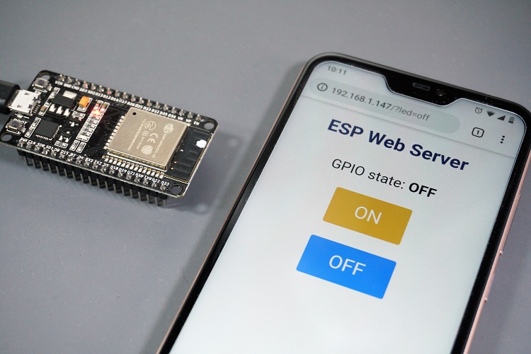
Wrapping Up
This tutorial showed you how to build a simple web server with MicroPython firmware to control the ESP32/ESP8266 GPIOs using sockets and the Python socket library.
If you’re looking for a web server tutorial with Arduino IDE, you can check the following resources:
ESP32 Web Server – Arduino IDE
ESP8266 Web Server – Arduino IDE
If you’re looking for more projects with the ESP32 and ESP8266 boards, you can take a look at the following:
20+ ESP32 Projects and Tutorials
30+ ESP8266 Projects
We hope you’ve found this article about how to build a web server with MicroPython useful.
To learn more about MicroPython, take a look at our eBook: SMART HOME with Raspberry Pi, ESP32, ESP8266 [eBook]
ESP32/ESP8266 Plot Sensor Readings in Real Time Charts – Web Server
Learn how to plot sensor readings (temperature, humidity, and pressure) on a web server using the ESP32 or ESP8266 with Arduino IDE. The ESP will host a web page with three real-time charts that have new readings added every 30 seconds.
Project Overview
In this tutorial we’ll build an asynchronous web server using the ESPAsyncWebServer library .
The HTML to build the web page will be stored on the ESP32 or ESP8266 Filesystem (SPIFFS).
To learn more about building a web server using SPIFFS, you can refer to the next tutorials:
ESP32 Web Server using SPIFFS (SPI Flash File System)
ESP8266 Web Server using SPIFFS (SPI Flash File System)
We’ll display temperature, humidity and pressure readings from a BME280 sensor on a chart, but you can modify this project to display sensor readings from any other sensor.
To learn more about the BME280, read our guides:
Watch the Video Demonstration
To see how the project works, you can watch the following video demonstration:Prerequisites
Make sure you check all the prerequisites in this section before continuing with the project in order to compile the code.
1.Install ESP Board in Arduino IDE
We’ll program the ESP32 and ESP8266 using Arduino IDE. So, you must have the ESP32 or ESP8266 add-on installed. Follow one of the next tutorials to install the ESP add-on: Installing ESP32 Board in Arduino IDE (Windows, Mac OS X, Linux) Installing ESP8266 Board in Arduino IDE (Windows, Mac OS X, Linux)2.Filesystem Uploader Plugin
To upload the HTML file to the ESP32 and ESP8266 flash memory, we’ll use a plugin for Arduino IDE:3.Installing Libraries
To build the asynchronous web server, you need to install the following libraries.Parts Required
To follow this tutorial you need the following parts:
ESP32 or ESP8266 (read ESP32 vs ESP8266 )
BME280 sensor
Breadboard
Jumper wires
Schematic Diagram
The BME280 sensor module we’re using communicates via I2C communication protocol, so you need to connect it to the ESP32 or ESP8266 I2C pins.
BME280 wiring to ESP32
| SCK (SCL Pin) | GPIO 22 |
| SDI (SDA pin) | GPIO 21 |
BME280 wiring to ESP8266
| SCK (SCL Pin) | GPIO 5 |
| SDI (SDA pin) | GPIO 4 |
Organizing your Files
To build the web server you need two different files.
The Arduino sketch and the HTML file.
The HTML file should be saved inside a folder called
Creating the HTML File
Create anindex.htmlfile with the following content orArduino Sketch
Copy the following code to the Arduino IDE orHow the code works
Let’s take a quick look at the code and see how it works.Including libraries
First, include the necessary libraries. You include different libraries depending on the board you’re using. If you’re using an ESP32, the code loads the following libraries: #include <WiFi.h> #include <ESPAsyncWebServer.h> #include <SPIFFS.h> #include <WiFi.h> #include <ESPAsyncWebServer.h> #include <SPIFFS.h> If you’re using an ESP8266, the code loads these libraries: #include <Arduino.h> #include <ESP8266WiFi.h> #include <Hash.h> #include <ESPAsyncTCP.h> #include <ESPAsyncWebServer.h> #include <FS.h> #include <Wire.h> #include <Adafruit_Sensor.h> #include <Adafruit_BME280.h> Create an instance to communicate with the BME280 sensor using I2C: Adafruit_BME280 bme; // I2C Insert your network credentials in the following variables: // Replace with your network credentials const char* ssid = "REPLACE_WITH_YOUR_SSID"; const char* password = "REPLACE_WITH_YOUR_PASSWORD"; Create AsyncWebServer object on port 80: AsyncWebServer server(80);Read Temperature, Humidity and Pressure
Then, we create three functions readBME280Temperature(), readBME280Humidity() and readBME280Pressure(). These functions request the temperature, humidity and pressure from the BME280 sensor and return the readings as a String type. String readBME280Temperature() { // Read temperature as Celsius (the default) float t = bme.readTemperature(); // Convert temperature to Fahrenheit //t = 1.8 * t + 32; if (isnan(t)) { Serial.println("Failed to read from BME280 sensor!"); return ""; } else { Serial.println(t); return String(t); } }Init BME280
In the setup(), initialize the sensor: status = bme.begin(0x76); if (!status) { Serial.println("Could not find a valid BME280 sensor, check wiring!"); while (1); }Init SPIFFS
Initialize the filesystem (SPIFFS): if(!SPIFFS.begin()){ Serial.println("An Error has occurred while mounting SPIFFS"); return; }Connect to Wi-Fi
Connect to Wi-Fi and print the IP address in the Serial Monitor: WiFi.begin(ssid, password); while (WiFi.status() != WL_CONNECTED) { delay(1000); Serial.println("Connecting to WiFi.."); } // Print ESP32 Local IP Address Serial.println(WiFi.localIP());Handle requests
Then, we need to handle what happens when the ESP receives a request. When it receives a request on the root URL, we send the HTML text that is saved in SPIFFS under the index.html name: server.on("/", HTTP_GET, [](AsyncWebServerRequest *request){ request->send(SPIFFS, "/index.html"); }); When we receive a request on the /temperature, /humidity or /pressure URLs, call the functions that return the sensor readings. For example, if we receive a request on the /temperature URL, we call the readBME280Temperature() function that returns the temperature. server.on("/temperature", HTTP_GET, [](AsyncWebServerRequest *request){ request->send_P(200, "text/plain", readBME280Temperature().c_str()); }); The same happens for the other readings. Finally, start the server: server.begin(); Because this is an asynchronous web server we don’t need to write anything in the loop(). void loop(){ }Uploading Code and Files
Save the code asESP_Chart_Web_Serveror download all project files here .
Go to
Then, upload the code to your board.
Make sure you have the right board and COM port selected.
Also, make sure you’ve inserted your networks credentials in the code.
When everything is successfully uploaded, open the Serial Monitor at a baud rate of 115200.
Press the board “
Demonstration
Open a browser on your local network and type the ESP32 or ESP8266 IP address.
You should see three charts.
A new data point is added every 30 seconds to a total of 40 points.
New data keeps being displayed on the charts as long as you have your web browser tab open.
Here is an example of the humidity chart:
 You can select each point to see the exact timestamp.

Wrapping Up
In this tutorial you’ve learned how to create charts to display data in your web server.
You can modify this project to create as many charts as you want and using any other sensors.
Next, we recommend building a project that displays charts from data stored on your database .
Here are other tutorials that you might like:
Visualize Your ESP32/ESP8266 Sensor Readings from Anywhere in the World
ESP32/ESP8266 Insert Data into MySQL Database using PHP and Arduino IDE
Learn more about the ESP32 with our best-selling course:
Learn ESP32 with Arduino IDE (eBook + Video Course)
Thank you for reading.
SMART HOME with Raspberry Pi, ESP32, ESP8266 [eBook]
ESP32 Publish Sensor Readings to Google Sheets (ESP8266 Compatible)
In this tutorial we’re going to show you how to publish sensor readings to Google Sheets using ESP32 or ESP8266 board. As an example, we’ll publish temperature, humidity, and pressure readings using the BME280 sensor to a Google Sheets spreadsheet every 30 minutes – we’ll be using IFTTT. You can use IFTTT to integrate with Google Sheets, but at the moment we recommend integrating with Google Sheets using a Google Service Account instead.
We recommend following this tutorial: ESP32 Datalogging to Google Sheets (using Google Service Account) .
You can use IFTTT to integrate with Google Sheets, but at the moment we recommend integrating with Google Sheets using a Google Service Account instead.
We recommend following this tutorial: ESP32 Datalogging to Google Sheets (using Google Service Account) .
Project Overview
The following figure shows an overview of what you’ll achieve by the end of this project.
 First, the ESP connects to your Wi-Fi network;
Then, the BME280 takes the temperature, humidity, and pressure readings;
Your ESP32 or ESP8266 communicates with the IFTTT Webhooks service that publishes thereadings to a spreadsheet on Google Sheets that is saved in your Google Drive’s folder;
After publishing the readings, the ESP goes into deep sleep mode for 30 minutes;
After 30 minutes the ESP wakes up;
After waking up, the ESP connects to Wi-Fi, and the process repeats.
First, the ESP connects to your Wi-Fi network;
Then, the BME280 takes the temperature, humidity, and pressure readings;
Your ESP32 or ESP8266 communicates with the IFTTT Webhooks service that publishes thereadings to a spreadsheet on Google Sheets that is saved in your Google Drive’s folder;
After publishing the readings, the ESP goes into deep sleep mode for 30 minutes;
After 30 minutes the ESP wakes up;
After waking up, the ESP connects to Wi-Fi, and the process repeats.
Creating Your IFTTT Account
For this project we’ll be using IFTTT to integrate with Google Sheets.
So, the first step is creating an account on IFTTT if you don’t have one.
Creating an account on IFTTT is free!
Go the official site: ifttt.com and enter your email to get started.

Creating an Applet
Next, you need to create a new applet.
Follow the next steps to create a new applet:


Testing Your Applet
Before proceeding with the project, it is very important to test your applet first.
Follow the next steps to test your applet.


 Continue reading this post to see how to integrate the IFTTT Google Sheets service with your ESP32 or ESP8266.
Parts Required
For this example we’ll take sensor readings from the BME280 sensor.
Here’s a list of parts you need to build the circuit for this project:
ESP32 board (read Best ESP32 development boards comparison )
Alternative – ESP8266 board (read Best ESP8266 dev boards )
BME280 sensor
Jumper wires
Breadboard
Schematics
The BME280 sensor we’re using in this example can communicate with the ESP32/ESP8266 using I2C communication protocol.
So, we’re going to use the ESP I2C pins.
BME280 with ESP32
Follow the next schematic diagram to wire the BME280 sensor if you’re using an ESP32.
(This schematic uses the ESP32 DEVKIT V1 module version with 36 GPIOs – if you’re using another model, please check the pinout for the board you’re using.)
BME280 with ESP8266
Follow the next schematic diagram if you’re using an ESP8266 12E.
Installing the BME280 library
To take readings from the BME280 sensor module we’ll use the Adafruit_BME280 library .
Follow the next steps to install the library in your Arduino IDE:
Open your Arduino IDE and go toInstalling the Adafruit_Sensor library
To use the BME280 library, you also need to install the Adafruit_Sensor library .
Follow the next steps to install the library in your Arduino IDE:
Go toAfter installing the libraries, restart your Arduino IDE.
Code
There’s an add-on for the Arduino IDE allows you to program the ESP32 using the Arduino IDE and its programming language.
Follow one of the next tutorials to prepare your Arduino IDE, if you haven’t already.
Including your SSID and password
The first thing you need to modify in the code is writing your network credentials: the SSID and password on the following lines: // Replace with your SSID and Password const char* ssid = "REPLACE_WITH_YOUR_SSID"; const char* password = "REPLACE_WITH_YOUR_PASSWORD";Including your unique IFTTT URL resource
Then, you need to write your unique IFTTT URL resource. Go back to “Testing your Applet” section bullet 2) to get your unique IFTTT URL resource. // Replace with your unique IFTTT URL resource const char* resource = "REPLACE_WITH_YOUR_IFTTT_URL_RESOURCE"; In my case, my resource is: /trigger/bme280_readings/with/key/nAZjOphL3d-ZO4N3k64-1A7gTlNSrxMJdmqy3 So, that line in the code looks as follows: const char* resource = "/trigger/bme280_readings/with/key/nAZjOphL3d-ZO4N3k64-1A7gTlNSrxMJdmqy3";Setting the sleep time
In this example we’ve set the sleep time to 30 minutes. This means that every 30 minutes the ESP wakes up, takes the readings, and publishes in your Google Sheets spreadsheet. The sleep time is set in the TIME_TO_SLEEP variable in seconds: // sleep for 30 minutes = 1800 seconds uint64_t TIME_TO_SLEEP = 1800; If you want to change the sleep time, you need to change the TIME_TO_SLEEP variable. Note that you should enter the sleep time in the TIME_TO_SLEEP variable in seconds.Sending the BME280 readings
The BME280 sensor readings are sent using the jsonObject variable as shown in the following line: String jsonObject = String("{\"value1\":\"") + bme.readTemperature() + "\",\"value2\":\"" + (bme.readPressure()/100.0F) + "\",\"value3\":\"" + bme.readHumidity() + "\"}";Publish temperature in Fahrenheit
In order to publish the temperature in Fahrenheit, you need to comment and uncomment the code like this: // Temperature in Celsius /*String jsonObject = String("{\"value1\":\"") + bme.readTemperature() + "\",\"value2\":\"" + (bme.readPressure()/100.0F) + "\",\"value3\":\"" + bme.readHumidity() + "\"}";*/ // Comment the previous line and uncomment the next line to publish temperature readings in Fahrenheit String jsonObject = String("{\"value1\":\"") + (1.8 * bme.readTemperature() + 32) + "\",\"value2\":\"" + (bme.readPressure()/100.0F) + "\",\"value3\":\"" + bme.readHumidity() + "\"}";Demonstration
After making all the necessary changes.
Upload the code to your ESP32 or ESP8266.
Make sure you select the right board and COM port.
Every 30 minutes, the ESP32 or ESP8266 wakes up to take sensor readings and publishes the readings in a spreadsheet on Google Sheets.
 The ESP32 chip has a built-in clock, so the readings are very accurate and it publishes to the spreadsheet every 30 minutes.
On the other hand, the ESP8266 publishes new readings approximately every 28 to 29 minutes.
The ESP32 chip has a built-in clock, so the readings are very accurate and it publishes to the spreadsheet every 30 minutes.
On the other hand, the ESP8266 publishes new readings approximately every 28 to 29 minutes.
Wrapping Up
In this post we’ve shown you how to publish your sensor readings with your ESP32 or ESP8266 to a spreadsheet on Google Sheets using the IFTTT platform.
As an example, we’ve published readings from the BME280 sensor.
We’ve also used the ESP deep sleep capabilities to save power.
This way, the ESP is awake only when we need to take readings.
You should be able to take this project example and apply it to your own projects.
Please note that this method has some limitations: first, it uses a third party service, and second, you need to be careful with the amount of requests you make in one day.
However, this method works very well and it is easy to implement.
If you like ESP32 and you want to learn more, make sure you check our course exclusively dedicated to the ESP32: ESP32/ESP8266 Send Email Notification using PHP Script
In this project, you’ll build an ESP32 or ESP8266 client that makes an HTTP POST request to a PHP script to send an email notification with sensor readings. Updated on 27 March 2023
You can also set a threshold value, so your email notification is only sent if the temperature/humidity/pressure is above a certain value.
As an example, we’ll be using a BME280 sensor connected to an ESP32 or ESP8266 board.
You can modify the code provided to send readings from a different sensor or even use multiple boards.
This is a great way to send email notifications using the ESP32 or ESP8266 without relying on IFTTT or an SMTP server.
In order to build this project, you will:
This project is also a great addition to build upon our previous projects:
ESP32/ESP8266 Insert Data into MySQL Database using PHP and Arduino IDE
Visualize Your Sensor Readings from Anywhere in the World
Updated on 27 March 2023
You can also set a threshold value, so your email notification is only sent if the temperature/humidity/pressure is above a certain value.
As an example, we’ll be using a BME280 sensor connected to an ESP32 or ESP8266 board.
You can modify the code provided to send readings from a different sensor or even use multiple boards.
This is a great way to send email notifications using the ESP32 or ESP8266 without relying on IFTTT or an SMTP server.
In order to build this project, you will:
This project is also a great addition to build upon our previous projects:
ESP32/ESP8266 Insert Data into MySQL Database using PHP and Arduino IDE
Visualize Your Sensor Readings from Anywhere in the World
1.Hosting Your PHP Application
The goal of this project is to have your own domain name and hosting account that allows you to send email notifications (without using an SMTP server, IFTTT, etc…). Here’s a high-level overview of how the project works: I recommend using one of the following hosting services that can handle all the project requirements:
Bluehost (user-friendly with cPanel) : free domain name when you sign up for the 3-year plan.
I recommend choosing the unlimited websites option;
Digital Ocean : Linux server that you manage through a command line.
I only recommended this option for advanced users.
Those two services are the ones that I use and personally recommend, but you can use any other hosting service.
Any hosting service that offers PHP and MySQL will work with this tutorial.
If you don’t have a hosting account, I recommend signing up for Bluehost .
Get Hosting and Domain Name with Bluehost
When buying a hosting account, you’ll also have to purchase a domain name.
If you like our projects, you might consider signing up for one of the recommended hosting services, because you’ll be supporting our work.
I recommend using one of the following hosting services that can handle all the project requirements:
Bluehost (user-friendly with cPanel) : free domain name when you sign up for the 3-year plan.
I recommend choosing the unlimited websites option;
Digital Ocean : Linux server that you manage through a command line.
I only recommended this option for advanced users.
Those two services are the ones that I use and personally recommend, but you can use any other hosting service.
Any hosting service that offers PHP and MySQL will work with this tutorial.
If you don’t have a hosting account, I recommend signing up for Bluehost .
Get Hosting and Domain Name with Bluehost
When buying a hosting account, you’ll also have to purchase a domain name.
If you like our projects, you might consider signing up for one of the recommended hosting services, because you’ll be supporting our work.
2.PHP Script HTTP – Send Email Notification
After signing up for a hosting account and setting up a domain name , you can login to your cPanel or similar dashboard. After that, follow the next steps to create a PHP script that is responsible for receiving incoming requests from the ESP32/ESP8266 and sending an email. If you’re using a hosting provider with cPanel, go to Advanced and search for “ Then, select the
 Edit the newly created file (email-notification.php) and copy the following script:
<?php
/*
Rui Santos
Complete project details at https://RandomNerdTutorials.com/esp32-esp8266-send-email-notification/
Permission is hereby granted, free of charge, to any person obtaining a copy
of this software and associated documentation files.
The above copyright notice and this permission notice shall be included in all
copies or substantial portions of the Software.
*/
// Receiver Email Address (where to send email notification)
$email_address = " [emailprotected] ";
// Keep this API Key value to be compatible with the ESP code provided in the project page.
If you change this value, the ESP sketch needs to match
$api_key_value = "tPmAT5Ab3j7F9";
$api_key = $value1 = $value2 = $value3 = "";
if ($_SERVER["REQUEST_METHOD"] == "POST") {
$api_key = test_input($_POST["api_key"]);
if($api_key == $api_key_value) {
$value1 = test_input($_POST["value1"]);
$value2 = test_input($_POST["value2"]);
$value3 = test_input($_POST["value3"]);
// Email message
$email_msg = "Temperature: " .
$value1 .
"oC\nHumidity: " .
$value2 .
"%\nPressure: " .
$value3 .
"hPa";
// Use wordwrap() if lines are longer than 70 characters
$email_msg = wordwrap($email_msg, 70);
// Uncomment the next if statement to set a threshold
// ($value1 = temperature, $value2 = humidity, $value3 = pressure)
/*if($value1 < 24.0){
echo "Temperature below threshold, don't send email";
exit;
}*/
// send email with mail(receiver email address, email subject, email message)
mail($email_address, "[NEW] ESP BME280 Readings", $email_msg);
echo "Email sent";
}
else {
echo "Wrong API Key provided.";
}
}
else {
echo "No data posted with HTTP POST.";
}
function test_input($data) {
$data = trim($data);
$data = stripslashes($data);
$data = htmlspecialchars($data);
return $data;
}
View raw code
Before saving the file, you need to modify the $email_address variable with the receiver email address:
// Receiver Email Address (where to send email notification)
$email_address = " [emailprotected] ";
After adding the receiver email, save the file and continue with this tutorial.
If you try to access your domain name in the next URL path, you’ll see the following:
https://example.com/email-notification.php
Edit the newly created file (email-notification.php) and copy the following script:
<?php
/*
Rui Santos
Complete project details at https://RandomNerdTutorials.com/esp32-esp8266-send-email-notification/
Permission is hereby granted, free of charge, to any person obtaining a copy
of this software and associated documentation files.
The above copyright notice and this permission notice shall be included in all
copies or substantial portions of the Software.
*/
// Receiver Email Address (where to send email notification)
$email_address = " [emailprotected] ";
// Keep this API Key value to be compatible with the ESP code provided in the project page.
If you change this value, the ESP sketch needs to match
$api_key_value = "tPmAT5Ab3j7F9";
$api_key = $value1 = $value2 = $value3 = "";
if ($_SERVER["REQUEST_METHOD"] == "POST") {
$api_key = test_input($_POST["api_key"]);
if($api_key == $api_key_value) {
$value1 = test_input($_POST["value1"]);
$value2 = test_input($_POST["value2"]);
$value3 = test_input($_POST["value3"]);
// Email message
$email_msg = "Temperature: " .
$value1 .
"oC\nHumidity: " .
$value2 .
"%\nPressure: " .
$value3 .
"hPa";
// Use wordwrap() if lines are longer than 70 characters
$email_msg = wordwrap($email_msg, 70);
// Uncomment the next if statement to set a threshold
// ($value1 = temperature, $value2 = humidity, $value3 = pressure)
/*if($value1 < 24.0){
echo "Temperature below threshold, don't send email";
exit;
}*/
// send email with mail(receiver email address, email subject, email message)
mail($email_address, "[NEW] ESP BME280 Readings", $email_msg);
echo "Email sent";
}
else {
echo "Wrong API Key provided.";
}
}
else {
echo "No data posted with HTTP POST.";
}
function test_input($data) {
$data = trim($data);
$data = stripslashes($data);
$data = htmlspecialchars($data);
return $data;
}
View raw code
Before saving the file, you need to modify the $email_address variable with the receiver email address:
// Receiver Email Address (where to send email notification)
$email_address = " [emailprotected] ";
After adding the receiver email, save the file and continue with this tutorial.
If you try to access your domain name in the next URL path, you’ll see the following:
https://example.com/email-notification.php
 If you see that message, it means that everything is being setup properly.
You can continue with this project.
If you see that message, it means that everything is being setup properly.
You can continue with this project.
3.Setting Up Your ESP32 or ESP8266
This project is compatible with both the ESP32 and ESP8266 boards. You just need to assemble a simple circuit and upload the sketch provided to publish temperature, humidity, and pressure readings to your PHP script, which will then be responsible to handle email notifications. The sketch is slightly different for each board.Parts Required
For this example, we’ll get sensor readings from the BME280 sensor. Here’s a list of parts you need to build the circuit for this project: ESP32 board (read Best ESP32 dev boards ) Alternative – ESP8266 board (read Best ESP8266 dev boards ) BME280 sensor Jumper wires BreadboardSchematics
The BME280 sensor module we’re using communicates via I2C communication protocol, so you need to connect it to the ESP32 or ESP8266 I2C pins.BME280 wiring to ESP32
| SCK (SCL Pin) | GPIO 22 |
| SDI (SDA pin) | GPIO 21 |
BME280 wiring to ESP8266
| SCK (SCL Pin) | GPIO 5 |
| SDI (SDA pin) | GPIO 4 |
Installing Libraries
We’ll program the ESP32/ESP8266 using Arduino IDE, so you must have the ESP32/ESP8266 add-on installed in your Arduino IDE. Follow one of the next tutorials depending on the board you’re using: Install the ESP32 Board in Arduino IDE – you also need to install the BME280 Library and Adafruit_Sensor library Install the ESP8266 Board in Arduino IDE – you also need to install the BME280 Library and Adafruit_Sensor libraryESP32 Code
Follow this section if you’re using an ESP32.. After installing the necessary board add-ons, copy the following code to your Arduino IDE, but don’t upload it yet. You need to make some changes to make it work for you. /* Rui Santos Complete project details at https://RandomNerdTutorials.com/esp32-esp8266-send-email-notification/ Permission is hereby granted, free of charge, to any person obtaining a copy of this software and associated documentation files. The above copyright notice and this permission notice shall be included in all copies or substantial portions of the Software. */ #include <WiFi.h> #include <WiFiClientSecure.h> #include <HTTPClient.h> #include <Wire.h> #include <Adafruit_Sensor.h> #include <Adafruit_BME280.h> // Replace with your network credentials const char* ssid = "REPLACE_WITH_YOUR_SSID"; const char* password = "REPLACE_WITH_YOUR_PASSWORD"; // REPLACE with your Domain name and URL path or IP address with path const char* serverName = "https://example.com/email-notification.php"; // Keep this API Key value to be compatible with the PHP code provided in the project page. // If you change the apiKeyValue value, the PHP file /email-notification.php also needs to have the same key String apiKeyValue = "tPmAT5Ab3j7F9"; /*#include <SPI.h> #define BME_SCK 18 #define BME_MISO 19 #define BME_MOSI 23 #define BME_CS 5*/ #define SEALEVELPRESSURE_HPA (1013.25) Adafruit_BME280 bme; // I2C //Adafruit_BME280 bme(BME_CS); // hardware SPI //Adafruit_BME280 bme(BME_CS, BME_MOSI, BME_MISO, BME_SCK); // software SPI void setup() { Serial.begin(115200); WiFi.begin(ssid, password); Serial.println("Connecting"); while(WiFi.status() != WL_CONNECTED) { delay(500); Serial.print("."); } Serial.println(""); Serial.print("Connected to WiFi network with IP Address: "); Serial.println(WiFi.localIP()); // (you can also pass in a Wire library object like &Wire2) bool status = bme.begin(0x76); if (!status) { Serial.println("Could not find a valid BME280 sensor, check wiring or change I2C address!"); while (1); } //Check WiFi connection status if(WiFi.status()== WL_CONNECTED){ WiFiClientSecure *client = new WiFiClientSecure; client->setInsecure(); //don't use SSL certificate HTTPClient https; // Your Domain name with URL path or IP address with path https.begin(*client, serverName); // Specify content-type header https.addHeader("Content-Type", "application/x-www-form-urlencoded"); // Prepare your HTTP POST request data String httpRequestData = "api_key=" + apiKeyValue + "&value1=" + String(bme.readTemperature()) + "&value2=" + String(bme.readHumidity()) + "&value3=" + String(bme.readPressure()/100.0F) + ""; Serial.print("httpRequestData: "); Serial.println(httpRequestData); // You can comment the httpRequestData variable above // then, use the httpRequestData variable below (for testing purposes without the BME280 sensor) //String httpRequestData = "api_key=tPmAT5Ab3j7F9&sensor=BME280&location=Office&value1=24.75&value2=49.54&value3=1005.14"; // Send HTTP POST request int httpResponseCode = https.POST(httpRequestData); // If you need an HTTP request with a content type: text/plain //https.addHeader("Content-Type", "text/plain"); //int httpResponseCode = https.POST("Hello, World!"); // If you need an HTTP request with a content type: application/json, use the following: //https.addHeader("Content-Type", "application/json"); //int httpResponseCode = https.POST("{\"value1\":\"19\",\"value2\":\"67\",\"value3\":\"78\"}"); if (httpResponseCode>0) { Serial.print("HTTP Response code: "); Serial.println(httpResponseCode); } else { Serial.print("Error code: "); Serial.println(httpResponseCode); } // Free resources https.end(); } else { Serial.println("WiFi Disconnected"); } // Use deep sleep to make the ESP send an email every X number of minutes/hours with low power consumption // ESP32 Deep Sleep Guide: https://RandomNerdTutorials.com/esp32-deep-sleep-arduino-ide-wake-up-sources/ } void loop() { } View raw codeSetting your network credentials
You need to modify the following lines with your network credentials: SSID and password. The code is well commented on where you should make the changes. // Replace with your network credentials const char* ssid = "REPLACE_WITH_YOUR_SSID"; const char* password = "REPLACE_WITH_YOUR_PASSWORD";Setting your serverName
You also need to type your domain name, so the ESP publishes the readings to your own server. const char* serverName = "https://example.com/email-notification.php"; Now, you can upload the code to your board.How the code works
Here’s a quick summary of how the code works: Import all the libraries to make it work (it will import either the ESP32 or ESP8266 libraries based on the selected board in your Arduino IDE); Set variables that you might want to change (apiKeyValue); The apiKeyValue is just a random string that you can modify. It’s used for security reasons, so only anyone that knows your API key can send email notifications. Initialize the serial communication for debugging purposes; Establish a Wi-Fi connection with your router; Initialize the BME280 sensor to get temperature, humidity, and pressure readings; Initialize a secure WiFi client. Then, in the rest of the setup() is where you actually make the HTTP POST with the latest BME280 readings: // Your Domain name with URL path or IP address with path http.begin(client, serverName); // Specify content-type header http.addHeader("Content-Type", "application/x-www-form-urlencoded"); // Prepare your HTTP POST request data String httpRequestData = "api_key=" + apiKeyValue + "&value1=" + String(bme.readTemperature()) + "&value2=" + String(bme.readHumidity()) + "&value3=" + String(bme.readPressure()/100.0F) + ""; int httpResponseCode = http.POST(httpRequestData); You can comment the httpRequestData variable above that concatenates all the BME280 readings and use the httpRequestData variable below for testing purposes: String httpRequestData = "api_key=tPmAT5Ab3j7F9&value1=24.75&value2=49.54&value3=1005.14"; Learn more about HTTPS Requests with the ESP32: ESP32 HTTPS Requests (Arduino IDE) .ESP8266 Code
Follow this section if you’re using an ESP8266.. After installing the necessary board add-ons, copy the following code to your Arduino IDE, but don’t upload it yet. You need to make some changes to make it work for you. /* Rui Santos Complete project details at https://RandomNerdTutorials.com/esp32-esp8266-send-email-notification/ Permission is hereby granted, free of charge, to any person obtaining a copy of this software and associated documentation files. The above copyright notice and this permission notice shall be included in all copies or substantial portions of the Software. */ #include <ESP8266WiFi.h> #include <ESP8266HTTPClient.h> #include <WiFiClientSecureBearSSL.h> #include <Wire.h> #include <Adafruit_Sensor.h> #include <Adafruit_BME280.h> // Replace with your network credentials const char* ssid = "REPLACE_WITH_YOUR_SSID"; const char* password = "REPLACE_WITH_YOUR_PASSWORD"; // REPLACE with your Domain name and URL path or IP address with path const char* serverName = "https://example.com/email-notification.php"; // Keep this API Key value to be compatible with the PHP code provided in the project page. // If you change the apiKeyValue value, the PHP file /email-notification.php also needs to have the same key String apiKeyValue = "tPmAT5Ab3j7F9"; /*#include <SPI.h> #define BME_SCK 18 #define BME_MISO 19 #define BME_MOSI 23 #define BME_CS 5*/ #define SEALEVELPRESSURE_HPA (1013.25) Adafruit_BME280 bme; // I2C //Adafruit_BME280 bme(BME_CS); // hardware SPI //Adafruit_BME280 bme(BME_CS, BME_MOSI, BME_MISO, BME_SCK); // software SPI void setup() { Serial.begin(115200); WiFi.begin(ssid, password); Serial.println("Connecting"); while(WiFi.status() != WL_CONNECTED) { delay(500); Serial.print("."); } Serial.println(""); Serial.print("Connected to WiFi network with IP Address: "); Serial.println(WiFi.localIP()); // (you can also pass in a Wire library object like &Wire2) bool status = bme.begin(0x76); if (!status) { Serial.println("Could not find a valid BME280 sensor, check wiring or change I2C address!"); while (1); } //Check WiFi connection status if(WiFi.status()== WL_CONNECTED){ std::unique_ptr<BearSSL::WiFiClientSecure>client(new BearSSL::WiFiClientSecure); // Ignore SSL certificate validation client->setInsecure(); //create an HTTPClient instance HTTPClient https; // Your Domain name with URL path or IP address with path https.begin(*client, serverName); // Specify content-type header https.addHeader("Content-Type", "application/x-www-form-urlencoded"); // Prepare your HTTP POST request data String httpRequestData = "api_key=" + apiKeyValue + "&value1=" + String(bme.readTemperature()) + "&value2=" + String(bme.readHumidity()) + "&value3=" + String(bme.readPressure()/100.0F) + ""; Serial.print("httpRequestData: "); Serial.println(httpRequestData); // You can comment the httpRequestData variable above // then, use the httpRequestData variable below (for testing purposes without the BME280 sensor) //String httpRequestData = "api_key=tPmAT5Ab3j7F9&sensor=BME280&location=Office&value1=24.75&value2=49.54&value3=1005.14"; // Send HTTP POST request int httpResponseCode = https.POST(httpRequestData); // If you need an HTTP request with a content type: text/plain //http.addHeader("Content-Type", "text/plain"); //int httpResponseCode = https.POST("Hello, World!"); // If you need an HTTP request with a content type: application/json, use the following: //http.addHeader("Content-Type", "application/json"); //int httpResponseCode = https.POST("{\"value1\":\"19\",\"value2\":\"67\",\"value3\":\"78\"}"); if (httpResponseCode>0) { Serial.print("HTTP Response code: "); Serial.println(httpResponseCode); } else { Serial.print("Error code: "); Serial.println(httpResponseCode); } // Free resources https.end(); } else { Serial.println("WiFi Disconnected"); } // Use deep sleep to make the ESP send an email every X number of minutes/hours with low power consumption // ESP8266 Deep Sleep Guide: https://RandomNerdTutorials.com/esp8266-deep-sleep-with-arduino-ide/ } void loop() { } View raw codeSetting your network credentials
You need to modify the following lines with your network credentials: SSID and password. The code is well commented on where you should make the changes. // Replace with your network credentials const char* ssid = "REPLACE_WITH_YOUR_SSID"; const char* password = "REPLACE_WITH_YOUR_PASSWORD";Setting your serverName
You also need to type your domain name, so the ESP publishes the readings to your own server. const char* serverName = "https://example.com/email-notification.php"; Now, you can upload the code to your board.Demonstration
After completing all the steps, power your ESP board and let it make an HTTP request to your server:
If everything is working properly, this is what you should see in your Arduino IDE Serial Monitor:
 Open your email client, you should have a new email with the subject “
 To send a new email, press the ESP on-board RESET/ENABLE button to restart it and new readings will be sent out via email.
For a final application, I recommend using deep sleep to make the ESP send an email every X number of minutes/hours with low power consumption.
Read one of these guides to add deep sleep to your sketch:
ESP32 Deep Sleep with Arduino IDE and Wake Up Sources
ESP8266 Deep Sleep with Arduino IDE
To send a new email, press the ESP on-board RESET/ENABLE button to restart it and new readings will be sent out via email.
For a final application, I recommend using deep sleep to make the ESP send an email every X number of minutes/hours with low power consumption.
Read one of these guides to add deep sleep to your sketch:
ESP32 Deep Sleep with Arduino IDE and Wake Up Sources
ESP8266 Deep Sleep with Arduino IDE
Enable Threshold Notification
Finally, keep in mind that every time you restart your ESP (or the ESP wakes from deep sleep), it will send a new email notification with the current values.
It might be useful to set a threshold value so that you only receive an email notification when your readings are above or below the threshold.
In your PHP script (email-notification.php), uncomment the following if statement:
// Uncomment the next if statement to set a threshold
// ($value1 = temperature, $value2 = humidity, $value3 = pressure)
/*if($value1 < 24.0){
echo "Temperature below threshold, don't send email";
exit;
}*/
It will look like this:
// Uncomment the next if statement to set a threshold
// ($value1 = temperature, $value2 = humidity, $value3 = pressure)
if($value1 < 24.0){
echo "Temperature below threshold, don't send email";
exit;
}
You can modify that if statement with the value threshold and only send an email based on that condition.
With the current code, it will only send an email notification when the temperature is above 24.0oC.
Wrapping Up
In this tutorial you’ve learned how to send emails with the ESP32 and ESP8266 using your own server and domain name .
The example provided is as simple as possible so that you can understand how everything works.
After understanding this example, you may change the email content, publish different sensor readings, use multiple ESP boards, and much more.
ESP32/ESP8266: Send BME280 Sensor Readings to InfluxDB
In this guide, you’ll learn how to send BME280 sensor readings to InfluxDB using the ESP32 or ESP8266 boards. InfluxDB is a time series database. Each record on the database is associated with a timestamp, which makes it ideal for datalogging IoT and Home Automation projects. Updated 14 May 2024
By the end of this tutorial, you’ll be able to build a dashboard as shown below to display all your sensor readings over time.
At the moment, dashboards are not compatible with InfluxdDB serverless .
You must use InfluxDB 2 (running on a Raspberry Pi, for example— see this post to set InfluxDB on Raspberry Pi .)
Updated 14 May 2024
By the end of this tutorial, you’ll be able to build a dashboard as shown below to display all your sensor readings over time.
At the moment, dashboards are not compatible with InfluxdDB serverless .
You must use InfluxDB 2 (running on a Raspberry Pi, for example— see this post to set InfluxDB on Raspberry Pi .)
 To get started with InfluxDB, read one of the following guides:
ESP32: Getting Started with InfluxDB
ESP8266 NodeMCU: Getting Started with InfluxDB
To get started with InfluxDB, read one of the following guides:
ESP32: Getting Started with InfluxDB
ESP8266 NodeMCU: Getting Started with InfluxDB
What is InfluxDB?
“For a more in-depth introduction to InfluxDB, check the following tutorials before proceeding: ESP32: Getting Started with InfluxDB ESP8266: Getting Started with InfluxDBWhy use InfluxDB Cloud? It’s a fast, elastic, serverless real-time monitoring platform, dashboarding engine, analytics service and event and metrics processor.” https://www.influxdata.com/products/influxdb-cloud/
Setting Up Influx DB
Set up InfluxDB. You have two options: Install InfluxDB 2 on Raspberry Pi (compatible with creating dashboards) Creating a serverless account ( not compatible with dashboards ) After setting up your account, you can proceed to the next section.Loading Data in InfluxDB


 The page that opens allows you to create buckets, and it also shows some sample code to interface the ESP8266 or ESP32 boards with InfluxDB.
Creating an InfluxDB Bucket

Getting InfluxDB URL and API Token
 * if you’re running InfluxDB locally on a Raspberry Pi, the URL will be the Raspberry Pi IP address on port 8086.
For example 192.168.1.106:8086.
* if you’re running InfluxDB locally on a Raspberry Pi, the URL will be the Raspberry Pi IP address on port 8086.
For example 192.168.1.106:8086.
API Tokens
If you’ve followed the previous steps, InfluxDB cloud has already created an API token for you that you could find in the snippet presented in the previous step. If you go to the Load Data icon and select API Tokens, you’ll find the previously generated API token. On this page, you can generate a new API token if needed.
At this moment, you should have saved the following:
InfluxDB Server URL
InfluxDB Organization
InfluxDB Bucket Name
API Token
On this page, you can generate a new API token if needed.
At this moment, you should have saved the following:
InfluxDB Server URL
InfluxDB Organization
InfluxDB Bucket Name
API Token
ESP32/ESP8266 Send Sensor Readings to InfluxDB
In this section, we’ll program the ESP32 and ESP8266 boards to send BME280 temperature, humidity, and pressure readings to InfluxDB.Parts Required
For this project, you need the following parts*: ESP32 or ESP8266 board (read ESP32 vs ESP8266 ); BME280 or any other sensor you’re familiar with; Breadboard ; Jumper wires . * you can also test the project with random values instead of sensor readings, or you can use any other sensor you’re familiar with.Schematic Diagram
In this tutorial, we’ll send BME280 sensor readings to InfluxDB. So, you need to wire the BME280 sensor to your board. Follow one of the next schematic diagrams.ESP32 with BME280
We’re going to use I2C communication with the BME280 sensor module. Wire the sensor to the default ESP32 SCL (GPIO 22) and SDA (GPIO 21) pins, as shown in the following schematic diagram.
Not familiar with the BME280 with the ESP32? Read this tutorial: ESP8266 with BME280
We’re going to use I2C communication with the BME280 sensor module. For that, wire the sensor to the ESP8266SDA (GPIO 4)andSCL (GPIO 5)pins, as shown in the following schematic diagram.
Not familiar with the BME280 with the ESP8266? Read this tutorial: Installing Libraries
For this project, you need to install the following libraries: InfluxDB Arduino Client Library Adafruit BME280 Library Adafruit Unified Sensor LibraryInstallation – Arduino IDE
If you’re using Arduino IDE, follow the next steps to install the library. Go to
Installation – VS Code
If you’re using VS Code with the PlatformIO extension, start by creating an Arduino project for your ESP32 or ESP8266 board. Then, click on the Follow the same procedure for the Adafruit BME280 library and Adafruit Unified Sensor library.
Your plaformio.ini file should look as follows (we also added a line to change the Serial Monitor baud rate to 115200).
monitor_speed = 115200
lib_deps =
tobiasschuerg/ESP8266 Influxdb@^3.12.0
adafruit/Adafruit BME280 Library@^2.2.2
adafruit/Adafruit Unified Sensor@^1.1.5
Follow the same procedure for the Adafruit BME280 library and Adafruit Unified Sensor library.
Your plaformio.ini file should look as follows (we also added a line to change the Serial Monitor baud rate to 115200).
monitor_speed = 115200
lib_deps =
tobiasschuerg/ESP8266 Influxdb@^3.12.0
adafruit/Adafruit BME280 Library@^2.2.2
adafruit/Adafruit Unified Sensor@^1.1.5
Send Sensor Readings to InfluxDB—Code
Copy the following code to the Arduino IDE or to the main.cpp file if you’re using VS Code with the PlatformIO extension. The code is compatible with both the ESP32 and ESP8266 boards. This code is based on this library example . We made a few modifications to include the BME280 sensor readings. /* Rui Santos Complete project details at our blog: https://RandomNerdTutorials.com/ Permission is hereby granted, free of charge, to any person obtaining a copy of this software and associated documentation files. The above copyright notice and this permission notice shall be included in all copies or substantial portions of the Software. */ // Based on this library example: https://github.com/tobiasschuerg/InfluxDB-Client-for-Arduino/blob/master/examples/SecureBatchWrite/SecureBatchWrite.ino #include <Arduino.h> #include <Wire.h> #include <Adafruit_Sensor.h> #include <Adafruit_BME280.h> #if defined(ESP32) #include <WiFiMulti.h> WiFiMulti wifiMulti; #define DEVICE "ESP32" #elif defined(ESP8266) #include <ESP8266WiFiMulti.h> ESP8266WiFiMulti wifiMulti; #define DEVICE "ESP8266" #define WIFI_AUTH_OPEN ENC_TYPE_NONE #endif #include <InfluxDbClient.h> #include <InfluxDbCloud.h> // WiFi AP SSID #define WIFI_SSID "REPLACE_WITH_YOUR_SSID" // WiFi password #define WIFI_PASSWORD "REPLACE_WITH_YOUR_PASSWORD" // InfluxDB v2 server url, e.g. https://eu-central-1-1.aws.cloud2.influxdata.com (Use: InfluxDB UI -> Load Data -> Client Libraries) #define INFLUXDB_URL "REPLACE_WITH_YOUR_DATABASE_URL" // InfluxDB v2 server or cloud API authentication token (Use: InfluxDB UI -> Load Data -> Tokens -> <select token>) #define INFLUXDB_TOKEN "REPLACE_WITH_YOUR_TOKEN" // InfluxDB v2 organization id (Use: InfluxDB UI -> Settings -> Profile -> <name under tile> ) #define INFLUXDB_ORG "REPLACE_WITH_YOUR_ORG" // InfluxDB v2 bucket name (Use: InfluxDB UI -> Load Data -> Buckets) #define INFLUXDB_BUCKET "SENSOR" // Set timezone string according to https://www.gnu.org/software/libc/manual/html_node/TZ-Variable.html // Examples: // Pacific Time: "PST8PDT" // Eastern: "EST5EDT" // Japanesse: "JST-9" // Central Europe: "CET-1CEST,M3.5.0,M10.5.0/3" #define TZ_INFO "WET0WEST,M3.5.0/1,M10.5.0" // InfluxDB client instance with preconfigured InfluxCloud certificate InfluxDBClient client(INFLUXDB_URL, INFLUXDB_ORG, INFLUXDB_BUCKET, INFLUXDB_TOKEN, InfluxDbCloud2CACert); // InfluxDB client instance without preconfigured InfluxCloud certificate for insecure connection //InfluxDBClient client(INFLUXDB_URL, INFLUXDB_ORG, INFLUXDB_BUCKET, INFLUXDB_TOKEN); // Data point Point sensorReadings("measurements"); //BME280 Adafruit_BME280 bme; // I2C float temperature; float humidity; float pressure; // Initialize BME280 void initBME(){ if (!bme.begin(0x76)) { Serial.println("Could not find a valid BME280 sensor, check wiring!"); while (1); } } void setup() { Serial.begin(115200); // Setup wifi WiFi.mode(WIFI_STA); wifiMulti.addAP(WIFI_SSID, WIFI_PASSWORD); Serial.print("Connecting to wifi"); while (wifiMulti.run() != WL_CONNECTED) { Serial.print("."); delay(500); } Serial.println(); //Init BME280 sensor initBME(); // Add tags sensorReadings.addTag("device", DEVICE); sensorReadings.addTag("location", "office"); sensorReadings.addTag("sensor", "bme280"); // Accurate time is necessary for certificate validation and writing in batches // For the fastest time sync find NTP servers in your area: https://www.pool.ntp.org/zone/ // Syncing progress and the time will be printed to Serial. timeSync(TZ_INFO, "pool.ntp.org", "time.nis.gov"); // Check server connection if (client.validateConnection()) { Serial.print("Connected to InfluxDB: "); Serial.println(client.getServerUrl()); } else { Serial.print("InfluxDB connection failed: "); Serial.println(client.getLastErrorMessage()); } } void loop() { // Get latest sensor readings temperature = bme.readTemperature(); humidity = bme.readHumidity(); pressure = bme.readPressure()/100.0F; // Add readings as fields to point sensorReadings.addField("temperature", temperature); sensorReadings.addField("humidity", humidity); sensorReadings.addField("pressure", pressure); // Print what are we exactly writing Serial.print("Writing: "); Serial.println(client.pointToLineProtocol(sensorReadings)); // Write point into buffer client.writePoint(sensorReadings); // Clear fields for next usage. Tags remain the same. sensorReadings.clearFields(); // If no Wifi signal, try to reconnect it if (wifiMulti.run() != WL_CONNECTED) { Serial.println("Wifi connection lost"); } // Wait 10s Serial.println("Wait 10s"); delay(10000); } View raw code Before uploading the code to your board, you need to insert your network credentials, the database URL, token, organization, and bucket name. Also, don’t forget to insert your timezone. Check this document to search for your timezone in the right format.How the Code Works
Start by including the required libraries and setting the DEVICE name accordingly to the selected board (ESP32 or ESP8266). #include <Arduino.h> #include <Wire.h> #include <Adafruit_Sensor.h> #include <Adafruit_BME280.h> #if defined(ESP32) #include <WiFiMulti.h> WiFiMulti wifiMulti; #define DEVICE "ESP32" #elif defined(ESP8266) #include <ESP8266WiFiMulti.h> ESP8266WiFiMulti wifiMulti; #define DEVICE "ESP8266" #define WIFI_AUTH_OPEN ENC_TYPE_NONE #endif #include <InfluxDbClient.h> #include <InfluxDbCloud.h> Insert your network credentials on the following variables so that the ESP32 or ESP8266 boards can connect to the internet using your local network. // WiFi AP SSID #define WIFI_SSID "REPLACE_WITH_YOUR_SSID" // WiFi password #define WIFI_PASSWORD "REPLACE_WITH_YOUR_PASSWORD" Insert the InfluxDB server URL on the following lines—: // InfluxDB v2 server url, e.g. https://eu-central-1-1.aws.cloud2.influxdata.com (Use: InfluxDB UI -> Load Data -> Client Libraries) #define INFLUXDB_URL "REPLACE_WITH_YOUR_INFLUXDB_URL"Setting your Timezone
You must set your timezone accordingly to these instructions . The easiest way is toInfluxDB Client
Now that you have all the required settings, you can create an InfluxDBClient instance. We’re creating a secure client that uses a preconfigured certificate— learn more about secure connection . InfluxDBClient client(INFLUXDB_URL, INFLUXDB_ORG, INFLUXDB_BUCKET, INFLUXDB_TOKEN, InfluxDbCloud2CACert);Point
Then, we create a Point instance called sensorReadings. The point will be called measurements on the database. Later in the code, we can refer to that point (sensorReadings) to add tags and fields. Point sensorReadings("measurements");BME280 Variables
Create an Adafruit_BME280 instance called bme on the default ESP I2C pins. Adafruit_BME280 bme; // I2C Create variables to save the temperature, humidity, and pressure readings. float temperature; float humidity; float pressure;initBME() function
The initBME() function initializes the BME280 sensor. We’ll call it later in the setup() to initialize the sensor. // Initialize BME280 void initBME(){ if (!bme.begin(0x76)) { Serial.println("Could not find a valid BME280 sensor, check wiring!"); while (1); } }setup()
In the setup(), initialize the Serial Monitor for debugging purposes. Serial.begin(115200); Initialize Wi-Fi. // Setup wifi WiFi.mode(WIFI_STA); wifiMulti.addAP(WIFI_SSID, WIFI_PASSWORD); Serial.print("Connecting to wifi"); while (wifiMulti.run() != WL_CONNECTED) { Serial.print("."); delay(500); } Serial.println(); Call the initBME() function to initialize the BME280 sensor. //Init BME280 sensor initBME(); Add tags to your data using addTag(). We’re adding the device name, the name of the sensor, and the location of the sensor. You may add other tags that might be useful for your specific project. sensorReadings.addTag("device", DEVICE); sensorReadings.addTag("location", "office"); sensorReadings.addTag("sensor", "bme280"); Synchronize time, which is necessary for certificate validation. timeSync(TZ_INFO, "pool.ntp.org", "time.nis.gov"); Check the connection to the InfluxDB server and print any error messages in case the connection fails: // Check server connection if (client.validateConnection()) { Serial.print("Connected to InfluxDB: "); Serial.println(client.getServerUrl()); } else { Serial.print("InfluxDB connection failed: "); Serial.println(client.getLastErrorMessage()); }loop()
In the loop(), we’ll send the sensor readings to InfluxDB every 10 seconds. We get temperature, humidity, and pressure readings: temperature = bme.readTemperature(); humidity = bme.readHumidity(); pressure = bme.readPressure()/100.0F; And we add those readings as fields to our point (database data row). // Add readings as fields to point sensorReadings.addField("temperature", temperature); sensorReadings.addField("humidity", humidity); sensorReadings.addField("pressure", pressure); Print in the Serial Monitor what we’re writing to the point: Serial.println(client.pointToLineProtocol(sensorReadings)); Finally, to actually add the point to the database, we use the writePoint() method on the InfluxDBClient object and pass as argument the point we want to add: client.writePoint(sensorReadings). client.writePoint(sensorReadings); Clear the fields to be ready for usage in the next loop. sensorReadings.clearFields(); New data is written to the database every 10 seconds. Serial.println("Wait 10s"); delay(10000);Demonstration—Visualizing your Data
After inserting all the required settings on the code, you can upload it to your ESP32/ESP8266 board.
If you get any error during compilation, check the following:
check that you have an ESP32/ESP8266 board selected in  Now, go to your InfludDB account and go to the
  Now, you can visualize your data.
Start by selecting the bucket you want.
Then, we need to add filters to select our data.
Select the
Now, you can visualize your data.
Start by selecting the bucket you want.
Then, we need to add filters to select our data.
Select the  You can create a dashboard to show multiple data visualizations in different formats (gauges, histogram, single stat, etc.) or different data on the same page.
For example, multiple charts to show temperature, humidity, and pressure, and boxes to show the current measurements.
You can create a dashboard to show multiple data visualizations in different formats (gauges, histogram, single stat, etc.) or different data on the same page.
For example, multiple charts to show temperature, humidity, and pressure, and boxes to show the current measurements.
Creating a Dashboard
This section is not compatible with InfluxdDB serverless . You must use InfluxDB 2 (running on a Raspberry Pi, for example— see this post to set InfluxDB on Raspberry Pi .) Click on the Repeat the same process for the other readings (humidity, and pressure).
You can also add a single stat to show the current values of each reading.
I have the ESP32 and ESP8266 running the same code simultaneously, so I created a dashboard that shows the readings of each board.
You can move your cells to different positions and organize the dashboard in a way that makes sense for you.
You can also customize the way the data is refreshed and how many data points you want to see (up to the past 30 days).
Repeat the same process for the other readings (humidity, and pressure).
You can also add a single stat to show the current values of each reading.
I have the ESP32 and ESP8266 running the same code simultaneously, so I created a dashboard that shows the readings of each board.
You can move your cells to different positions and organize the dashboard in a way that makes sense for you.
You can also customize the way the data is refreshed and how many data points you want to see (up to the past 30 days).
Wrapping Up
In this tutorial, you learned how to send multiple sensor readings to InfluxDB.
InfluxDB adds a timestamp to all data rows (point).
As an example, we used a BME280 sensor, but you can easily modify the example to use any other sensor or add more sensors.
You can also run this example on multiple boards to monitor the temperature, humidity, and pressure in different places—don’t forget to add different tags to identify the places or the boards.
We hope you found this tutorial useful.
What other projects would you like to see using InfluxDB? Let us know in the comments section.
Learn more about the ESP32 and ESP8266 with our resources:
Learn ESP32 with Arduino IDE
Home Automation using ESP8266
Build Web Servers with ESP32 and ESP8266
Firebase Web App with ESP32 and ESP8266
Free ESP32 Projects and Tutorials
Free ESP8266 Projects and Tutorials
ESP32/ESP8266 Thermostat Web Server – Control Output Based on Temperature
In this project, you’ll build an ESP32 / ESP8266 Thermostat Web Server with an input field to set a temperature threshold value. This allows you to automatically control an output based on the current temperature reading. The output will be set to on if the temperature is above or set to off if it’s below the threshold – this can be used to build a simple thermostat project. As an example, we’ll read the temperature using a DS18B20 temperature sensor.
You can use any other temperature sensor like DHT11/DHT22, BME280 or LM35 .
To better understand how this project works, we recommend reading these tutorials:
Input Data on HTML Form ESP32/ESP8266 Web Server (Arduino IDE)
ESP32 with DS18B20 (one sensor, multiple sensors, web server)
ESP8266 NodeMCU with DS18B20 (one sensor, multiple sensors, web server)
ESP32 Web Server or ESP8266 NodeMCU Web Server
As an example, we’ll read the temperature using a DS18B20 temperature sensor.
You can use any other temperature sensor like DHT11/DHT22, BME280 or LM35 .
To better understand how this project works, we recommend reading these tutorials:
Input Data on HTML Form ESP32/ESP8266 Web Server (Arduino IDE)
ESP32 with DS18B20 (one sensor, multiple sensors, web server)
ESP8266 NodeMCU with DS18B20 (one sensor, multiple sensors, web server)
ESP32 Web Server or ESP8266 NodeMCU Web Server
Project Overview
The following image shows a high-level overview of the project we’ll build.
 The ESP32/ESP8266 hosts a web server that shows the latest temperature readings from a DS18B20 temperature sensor.
There’s an input field to set up a temperature threshold value.
When the temperature goes above the threshold, an output will be automatically turned on.
You can invert this logic depending on your project application.
When the temperature goes below the threshold, the output will be turned off.
The system can be activated or deactivated through the web server.
If you choose to deactivate the system, the output will keep its state, no matter the temperature value.
The following image shows how the web server page looks like.
The ESP32/ESP8266 hosts a web server that shows the latest temperature readings from a DS18B20 temperature sensor.
There’s an input field to set up a temperature threshold value.
When the temperature goes above the threshold, an output will be automatically turned on.
You can invert this logic depending on your project application.
When the temperature goes below the threshold, the output will be turned off.
The system can be activated or deactivated through the web server.
If you choose to deactivate the system, the output will keep its state, no matter the temperature value.
The following image shows how the web server page looks like.

Prerequisites
Make sure you check each of the following prerequisites before proceeding with this project.
1.ESP32 or ESP8266 Add-on Arduino IDE
This project is compatible with both the ESP32 and ESP8266 boards. We’ll program these boards using Arduino IDE, so make sure you have the necessary add-ons installed: Install ESP32 Board in Arduino IDE Install ESP8266 Board in Arduino IDE2.Async Web Server Libraries
To build the asynchronous web server, you need to install these libraries.3.Parts Required
To follow this tutorial you need the following parts:
ESP32 (read Best ESP32 boards ) or ESP8266 (read Best ESP8266 boards )
LED
220 Ohm resistor
DS18B20 temperature sensor (waterproof version )
4.7k Ohm resistor
Jumper wires
Breadboard
Schematic Diagram
Before proceeding, wire the DS18B20 temperature sensor to your board.
ESP32 with DS18B20 and LED
If you’re using an ESP32, wire the DS18B20 temperature sensor as shown in the following schematic diagram, with the data pin connected to GPIO 4.
ESP8266 with DS18B20 and LED
If you’re using an ESP8266, wire the DS18B20 temperature sensor as shown in the following schematic diagram, with the data pin connected to GPIO 4 (D2).
Code – Thermostat Web Server with Threshold Input
Copy the following code to your Arduino IDE, but don’t upload it yet.
You need to make some changes to make it work for you.
You need to insert your network credentials and your default threshold value.
/*********
Rui Santos
Complete project details at https://RandomNerdTutorials.com/esp32-esp8266-thermostat-web-server/
Permission is hereby granted, free of charge, to any person obtaining a copy
of this software and associated documentation files.
The above copyright notice and this permission notice shall be included in all
copies or substantial portions of the Software.
*********/
#ifdef ESP32
#include <WiFi.h>
#include <AsyncTCP.h>
#else
#include <ESP8266WiFi.h>
#include <ESPAsyncTCP.h>
#endif
#include <ESPAsyncWebServer.h>
#include <Wire.h>
#include <OneWire.h>
#include <DallasTemperature.h>
// REPLACE WITH YOUR NETWORK CREDENTIALS
const char* ssid = "REPLACE_WITH_YOUR_SSID";
const char* password = "REPLACE_WITH_YOUR_PASSWORD";
// Default Threshold Temperature Value
String inputMessage = "25.0";
String lastTemperature;
String enableArmChecked = "checked";
String inputMessage2 = "true";
// HTML web page to handle 2 input fields (threshold_input, enable_arm_input)
const char index_html[] PROGMEM = R"rawliteral(
<!DOCTYPE HTML><html><head>
<title>Temperature Threshold Output Control</title>
<meta name="viewport" content="width=device-width, initial-scale=1">
</head><body>
<h2>DS18B20 Temperature</h2>
<h3>%TEMPERATURE% °C</h3>
<h2>ESP Arm Trigger</h2>
<form action="/get">
Temperature Threshold <input type="number" step="0.1" name="threshold_input" value="%THRESHOLD%" required><br>
Arm Trigger <input type="checkbox" name="enable_arm_input" value="true" %ENABLE_ARM_INPUT%><br><br>
<input type="submit" value="Submit">
</form>
</body></html>)rawliteral";
void notFound(AsyncWebServerRequest *request) {
request->send(404, "text/plain", "Not found");
}
AsyncWebServer server(80);
// Replaces placeholder with DS18B20 values
String processor(const String& var){
//Serial.println(var);
if(var == "TEMPERATURE"){
return lastTemperature;
}
else if(var == "THRESHOLD"){
return inputMessage;
}
else if(var == "ENABLE_ARM_INPUT"){
return enableArmChecked;
}
return String();
}
// Flag variable to keep track if triggers was activated or not
bool triggerActive = false;
const char* PARAM_INPUT_1 = "threshold_input";
const char* PARAM_INPUT_2 = "enable_arm_input";
// Interval between sensor readings.
Learn more about ESP32 timers: https://RandomNerdTutorials.com/esp32-pir-motion-sensor-interrupts-timers/
unsigned long previousMillis = 0;
const long interval = 5000;
// GPIO where the output is connected to
const int output = 2;
// GPIO where the DS18B20 is connected to
const int oneWireBus = 4;
// Setup a oneWire instance to communicate with any OneWire devices
OneWire oneWire(oneWireBus);
// Pass our oneWire reference to Dallas Temperature sensor
DallasTemperature sensors(&oneWire);
void setup() {
Serial.begin(115200);
WiFi.mode(WIFI_STA);
WiFi.begin(ssid, password);
if (WiFi.waitForConnectResult() != WL_CONNECTED) {
Serial.println("WiFi Failed!");
return;
}
Serial.println();
Serial.print("ESP IP Address: http://");
Serial.println(WiFi.localIP());
pinMode(output, OUTPUT);
digitalWrite(output, LOW);
// Start the DS18B20 sensor
sensors.begin();
// Send web page to client
server.on("/", HTTP_GET, [](AsyncWebServerRequest *request){
request->send_P(200, "text/html", index_html, processor);
});
// Receive an HTTP GET request at <ESP_IP>/get?threshold_input=<inputMessage>&enable_arm_input=<inputMessage2>
server.on("/get", HTTP_GET, [] (AsyncWebServerRequest *request) {
// GET threshold_input value on <ESP_IP>/get?threshold_input=<inputMessage>
if (request->hasParam(PARAM_INPUT_1)) {
inputMessage = request->getParam(PARAM_INPUT_1)->value();
// GET enable_arm_input value on <ESP_IP>/get?enable_arm_input=<inputMessage2>
if (request->hasParam(PARAM_INPUT_2)) {
inputMessage2 = request->getParam(PARAM_INPUT_2)->value();
enableArmChecked = "checked";
}
else {
inputMessage2 = "false";
enableArmChecked = "";
}
}
Serial.println(inputMessage);
Serial.println(inputMessage2);
request->send(200, "text/html", "HTTP GET request sent to your ESP.<br><a href=\"/\">Return to Home Page</a>");
});
server.onNotFound(notFound);
server.begin();
}
void loop() {
unsigned long currentMillis = millis();
if (currentMillis - previousMillis >= interval) {
previousMillis = currentMillis;
sensors.requestTemperatures();
// Temperature in Celsius degrees
float temperature = sensors.getTempCByIndex(0);
Serial.print(temperature);
Serial.println(" *C");
// Temperature in Fahrenheit degrees
/*float temperature = sensors.getTempFByIndex(0);
Serial.print(temperature);
Serial.println(" *F");*/
lastTemperature = String(temperature);
// Check if temperature is above threshold and if it needs to trigger output
if(temperature > inputMessage.toFloat() && inputMessage2 == "true" && !triggerActive){
String message = String("Temperature above threshold.
Current temperature: ") +
String(temperature) + String("C");
Serial.println(message);
triggerActive = true;
digitalWrite(output, HIGH);
}
// Check if temperature is below threshold and if it needs to trigger output
else if((temperature < inputMessage.toFloat()) && inputMessage2 == "true" && triggerActive) {
String message = String("Temperature below threshold.
Current temperature: ") +
String(temperature) + String(" C");
Serial.println(message);
triggerActive = false;
digitalWrite(output, LOW);
}
}
}
View raw code
How the Code Works
Continue reading to learn how the code works, or skip to the Demonstration section.
Libraries
Start by importing the required libraries. The WiFi (or ESP8266WiFi), AsyncTCP (or ESPAsyncTCP) and ESPAsyncWebServer are required to build the web server. The OneWire and DallasTemperature are required to interface with the DS18B20. The code automatically imports the right libraries accordingly to the selected board (ESP32 or ESP8266). #ifdef ESP32 #include <WiFi.h> #include <AsyncTCP.h> #else #include <ESP8266WiFi.h> #include <ESPAsyncTCP.h> #endif #include <ESPAsyncWebServer.h> #include <Wire.h> #include <OneWire.h> #include <DallasTemperature.h>Network Credentials
Insert your network credentials in the following lines: // REPLACE WITH YOUR NETWORK CREDENTIALS const char* ssid = "REPLACE_WITH_YOUR_SSID"; const char* password = "REPLACE_WITH_YOUR_PASSWORD";Default Temperature Threshold Value
In the inputMessage variable insert your default temperature threshold value. We’re setting it to 25.0, but you can set it yo any other value. String inputMessage = "25.0";Auxiliar Variables
The lastTemperature variable will hold the latest temperature reading to be compared with the threshold value. String lastTemperature; The enableArmChecked variable will tell us whether the checkbox to automatically control the output is checked or not. String enableArmChecked = "checked"; In case it’s checked, the value saved on the inputMessage2 should be set to true. String inputMessage2 = "true";HTML Text
Then, we have some basic HTML text to build a page with two input fields: a temperature threshold input field and a checkbox to enable or disable automatically controlling the output. The web page also displays the latest temperature reading from the DS18B20 temperature sensor. The following lines display the temperature: <h2>DS18B20 Temperature</h2> <h3>%TEMPERATURE% °C</h3> The %TEMPERATURE% is a placeholder that will be replaced by the actual temperature value when the ESP32/ESP8266 serves the page. Then, we have a form with two input fields and a “Submit” button. When the user types some data and clicks the “Submit” button, those values are sent to the ESP to update the variables. <form action="/get"> Temperature Threshold <input type="number" step="0.1" name="threshold_input" value="%THRESHOLD%" required><br> Arm Trigger <input type="checkbox" name="enable_arm_input" value="true" %ENABLE_ARM_INPUT%><br><br> <input type="submit" value="Submit"> </form> The first input field is of type number and the second input field is a checkbox. To learn more about input fields, we recommend taking a look at following resources of the w3schools website: HTML Input Tag HTML Input Types The action attribute of the form specifies where to send the data inserted on the form after pressing submit. In this case, it makes an HTTP GET request to: /get?threshold_input=value&enable_arm_input=value The value refers to the text you enter in each of the input fields. To learn more about handling input fields with the ESP32/ESP8266, read: Input Data on HTML Form ESP32/ESP8266 Web Server using Arduino IDE .processor()
The processor() function replaces all placeholders in the HTML text with the actual values. %TEMPERATURE% lastTemperature %THRESHOLD% inputMessage String processor(const String& var){ //Serial.println(var); if(var == "TEMPERATURE"){ return lastTemperature; } else if(var == "THRESHOLD"){ return inputMessage; } else if(var == "ENABLE_ARM_INPUT"){ return enableArmChecked; } return String(); }Input Field Parameters
The following variables will be used to check whether we’ve received an HTTP GET request from those input fields and save the values into variables accordingly. const char* PARAM_INPUT_1 = "threshold_input"; const char* PARAM_INPUT_2 = "enable_arm_input";Interval Between Readings
Every 5000 milliseconds (5 seconds), we’ll get a new temperature reading from the DS18B20 temperature sensor and compare it with the threshold value. To keep track of the time, we use timers . Change the interval variable if you want to change the time between each sensor reading. unsigned long previousMillis = 0; const long interval = 5000;GPIO Output
In this example, we’ll control GPIO 2. This GPIO is connected to the ESP32 and ESP8266 built-in LED, so it allows us to easily check if the project is working as expected. You can control any other output and for many applications you’ll want to control a relay module . // GPIO where the output is connected to const int output = 2;DS18B20 Temperature Sensor Init
Initialize the DS18B20 temperature sensor. // GPIO where the DS18B20 is connected to const int oneWireBus = 4; // Setup a oneWire instance to communicate with any OneWire devices OneWire oneWire(oneWireBus); // Pass our oneWire reference to Dallas Temperature sensor DallasTemperature sensors(&oneWire); To learn more about interfacing the DS18B20 temperature sensor with the ESP board, read: ESP32 DS18B20 Temperature Sensor ESP8266 NodeMCU DS18B20 Temperature Sensorsetup()
In the setup(), connect to Wi-Fi in station mode and print the ESP IP address: Serial.begin(115200); WiFi.mode(WIFI_STA); WiFi.begin(ssid, password); if (WiFi.waitForConnectResult() != WL_CONNECTED) { Serial.println("WiFi Failed!"); return; } Serial.println(); Serial.print("ESP IP Address: http://"); Serial.println(WiFi.localIP()); Set GPIO 2 as an output and set it to LOW when the ESP first starts. pinMode(output, OUTPUT); digitalWrite(output, LOW); Initialize the DS18B20 temperature sensor: sensors.begin();Handle Web Server
Then, define what happens when the ESP32 or ESP8266 receives HTTP requests. When we get a request on the root / url, send the HTML text with the processor (so that the placeholders are replaced with the latest values). server.on("/", HTTP_GET, [](AsyncWebServerRequest *request){ request->send_P(200, "text/html", index_html, processor); }); When, a form is submitted, the ESP receives a request on the following URL: <ESP_IP>/get?threshold_input=<inputMessage>&enable_arm_input=<inputMessage2> So, we check whether the request contains input parameters, and save those parameters into variables: server.on("/get", HTTP_GET, [] (AsyncWebServerRequest *request) { // GET threshold_input value on <ESP_IP>/get?threshold_input=<inputMessage> if (request->hasParam(PARAM_INPUT_1)) { inputMessage = request->getParam(PARAM_INPUT_1)->value(); // GET enable_arm_input value on <ESP_IP>/get?enable_arm_input=<inputMessage2> if (request->hasParam(PARAM_INPUT_2)) { inputMessage2 = request->getParam(PARAM_INPUT_2)->value(); enableArmChecked = "checked"; } else { inputMessage2 = "false"; enableArmChecked = ""; } } This is the part of the code where the variables will be replaced with the values submitted on the form. The inputMessage variable saves the temperature threshold value and the inputMessage2 saves whether the checkbox is ticked or not (if we should control the GPIO or not). After submitting the values on the form, it displays a new page saying the request was successfully sent to your board an with a link to return to the homepage. request->send(200, "text/html", "HTTP GET request sent to your ESP.<br><a href=\"/\">Return to Home Page</a>"); }); Finally, start the server: server.begin();loop()
In the loop(), we use timers to get new temperature readings every 5 seconds. unsigned long currentMillis = millis(); if (currentMillis - previousMillis >= interval) { previousMillis = currentMillis; sensors.requestTemperatures(); // Temperature in Celsius degrees float temperature = sensors.getTempCByIndex(0); Serial.print(temperature); Serial.println(" *C"); // Temperature in Fahrenheit degrees /*float temperature = sensors.getTempFByIndex(0); Serial.print(temperature); Serial.println(" *F");*/ lastTemperature = String(temperature); After getting a new temperature reading, we check whether it is above or below the threshold and turn the output on or off accordingly. In this example, we set the output state to HIGH, if all these conditions are met: The current temperature is above the threshold; Automatic output control is enabled (the checkbox is ticked on the web page); If the output hasn’t been triggered yet. // Check if temperature is above threshold and if it needs to trigger output if(temperature > inputMessage.toFloat() && inputMessage2 == "true" && !triggerActive){ String message = String("Temperature above threshold. Current temperature: ") + String(temperature) + String("C"); Serial.println(message); triggerActive = true; digitalWrite(output, HIGH); } Then, if the temperature goes below the threshold, set the output to LOW. else if((temperature < inputMessage.toFloat()) && inputMessage2 == "true" && triggerActive) { String message = String("Temperature below threshold. Current temperature: ") + String(temperature) + String(" C"); Serial.println(message); triggerActive = false; digitalWrite(output, LOW); } Depending on your application, you may want to change the output to LOW, when the temperature is above the threshold and to HIGH when the output is below the threshold.Demonstration – ESP Thermostat
Upload the code to your ESP board (with the DS18B20 wired to your ESP32 or ESP8266 board).
Open the Serial Monitor at a baud rate of 115200 and press the on-board RST/EN button.
The ESP will print its IP address and it will start displaying new temperature values every 5 seconds.
 Open a browser and type the ESP IP address.
A similar web page should load with the default values (defined in your code):
If the arm trigger is enabled (checkbox ticked) and if the temperature goes above the threshold, the LED should turn on (output is set to HIGH).
Open a browser and type the ESP IP address.
A similar web page should load with the default values (defined in your code):
If the arm trigger is enabled (checkbox ticked) and if the temperature goes above the threshold, the LED should turn on (output is set to HIGH).
 After that, if the temperature goes below the threshold, the output will turn off.
 You can use the web page input fields to change the threshold value or to arm and disarm controlling the output.
For any change to take effect, you just need to press the “Submit” button.
At the same time, you should get the new input fields in the Serial Monitor.
You can use the web page input fields to change the threshold value or to arm and disarm controlling the output.
For any change to take effect, you just need to press the “Submit” button.
At the same time, you should get the new input fields in the Serial Monitor.

Wrapping Up
In this project you’ve learn how to create a web server with a threshold value to automatically control an output accordingly to the current temperature reading thermostat web server).
As an example, we’ve controlled an LED.
For real world applications, you’ll probably want to control a relay module.
You can read the following guides to learn how to control a relay with the ESP:
ESP32 Relay Module – Control AC Appliances (Web Server)
ESP8266 NodeMCU Relay Module – Control AC Appliances (Web Server)
We’ve used raw HTML text, to make the project easier to follow.
We suggest adding some CSS to style your web page to make it look nicer.
You may also want to add email notifications to this project.
If you want to learn more about the ESP32 and ESP8266, try our projects and resources:
Learn ESP32 with Arduino IDE
Home Automation using ESP8266
MicroPython Programming with ESP32 and ESP8266
More ESP32 resources…
More ESP8266 resources…
ESP32/ESP8266 Web Server HTTP Authentication (Username and Password Protected)
Learn how to add HTTP authentication with username and password to your ESP32 and ESP8266 NodeMCU web server projects using Arduino IDE. You can only access your web server if you type the correct user and pass. If you logout, you can only access again if you enter the right credentials. The method we’ll use can be applied to web servers built using the ESPAsyncWebServer library. The ESP32/ESP8266 boards will be programmed using Arduino IDE.
So make sure you have these boards installed:
Installing ESP32 Board in Arduino IDE (Windows, Mac OS X, and Linux)
Installing ESP8266 Board in Arduino IDE (Windows, Mac OS X, Linux)
The ESP32/ESP8266 boards will be programmed using Arduino IDE.
So make sure you have these boards installed:
Installing ESP32 Board in Arduino IDE (Windows, Mac OS X, and Linux)
Installing ESP8266 Board in Arduino IDE (Windows, Mac OS X, Linux)
Security Concerns
This project is meant to be used in your local network to protect from anyone just typing the ESP IP address and accessing the web server (like unauthorized family member or friend).
If your network is properly secured, running an HTTP server with basic authentication is enough for most applications.
If someone has managed to hack your network, it doesn’t matter if you use HTTP or HTTPS.
The hacker can bypass HTTPS and get your user/pass.
Project Overview
Let’s take a quick look at the features of the project we’ll build.
 In this tutorial you’ll learn how to password protect your web server;
When you try to access the web server page on the ESP IP address, a window pops up asking for a username and password;
To get access to the web server page, you need to enter the right username and password (defined in the ESP32/ESP8266 sketch);
There’s a logout button on the web server.
If you click the logout button, you’ll be redirected to a logout page.
Then, close all web browser tabs to complete the logout process;
You can only access the web server again if you login with the right credentials;
If you try to access the web server from a different device (on the local network) you also need to login with the right credentials (even if you have a successful login on another device);
The authentication is not encrypted.
In this tutorial you’ll learn how to password protect your web server;
When you try to access the web server page on the ESP IP address, a window pops up asking for a username and password;
To get access to the web server page, you need to enter the right username and password (defined in the ESP32/ESP8266 sketch);
There’s a logout button on the web server.
If you click the logout button, you’ll be redirected to a logout page.
Then, close all web browser tabs to complete the logout process;
You can only access the web server again if you login with the right credentials;
If you try to access the web server from a different device (on the local network) you also need to login with the right credentials (even if you have a successful login on another device);
The authentication is not encrypted.
Installing Libraries – Async Web Server
To build the web server you need to install the following libraries:
Web Server Code with Authentication
Copy the following code to your Arduino IDE.
/*********
Rui Santos
Complete project details at https://RandomNerdTutorials.com/esp32-esp8266-web-server-http-authentication/
The above copyright notice and this permission notice shall be included in all
copies or substantial portions of the Software.
*********/
// Import required libraries
#ifdef ESP32
#include <WiFi.h>
#include <AsyncTCP.h>
#else
#include <ESP8266WiFi.h>
#include <ESPAsyncTCP.h>
#endif
#include <ESPAsyncWebServer.h>
// Replace with your network credentials
const char* ssid = "REPLACE_WITH_YOUR_SSID";
const char* password = "REPLACE_WITH_YOUR_PASSWORD";
const char* http_username = "admin";
const char* http_password = "admin";
const char* PARAM_INPUT_1 = "state";
const int output = 2;
// Create AsyncWebServer object on port 80
AsyncWebServer server(80);
const char index_html[] PROGMEM = R"rawliteral(
<!DOCTYPE HTML><html>
<head>
<title>ESP Web Server</title>
<meta name="viewport" content="width=device-width, initial-scale=1">
<style>
html {font-family: Arial; display: inline-block; text-align: center;}
h2 {font-size: 2.6rem;}
body {max-width: 600px; margin:0px auto; padding-bottom: 10px;}
.switch {position: relative; display: inline-block; width: 120px; height: 68px}
.switch input {display: none}
.slider {position: absolute; top: 0; left: 0; right: 0; bottom: 0; background-color: #ccc; border-radius: 34px}
.slider:before {position: absolute; content: ""; height: 52px; width: 52px; left: 8px; bottom: 8px; background-color: #fff; -webkit-transition: .4s; transition: .4s; border-radius: 68px}
input:checked+.slider {background-color: #2196F3}
input:checked+.slider:before {-webkit-transform: translateX(52px); -ms-transform: translateX(52px); transform: translateX(52px)}
</style>
</head>
<body>
<h2>ESP Web Server</h2>
<button onclick="logoutButton()">Logout</button>
<p>Ouput - GPIO 2 - State <span>%STATE%</span></p>
%BUTTONPLACEHOLDER%
<script>function toggleCheckbox(element) {
var xhr = new XMLHttpRequest();
if(element.checked){
xhr.open("GET", "/update?state=1", true);
document.getElementById("state").innerHTML = "ON";
}
else {
xhr.open("GET", "/update?state=0", true);
document.getElementById("state").innerHTML = "OFF";
}
xhr.send();
}
function logoutButton() {
var xhr = new XMLHttpRequest();
xhr.open("GET", "/logout", true);
xhr.send();
setTimeout(function(){ window.open("/logged-out","_self"); }, 1000);
}
</script>
</body>
</html>
)rawliteral";
const char logout_html[] PROGMEM = R"rawliteral(
<!DOCTYPE HTML><html>
<head>
<meta name="viewport" content="width=device-width, initial-scale=1">
</head>
<body>
<p>Logged out or <a href="/">return to homepage</a>.</p>
<p><strong>Note:</strong> close all web browser tabs to complete the logout process.</p>
</body>
</html>
)rawliteral";
// Replaces placeholder with button section in your web page
String processor(const String& var){
//Serial.println(var);
if(var == "BUTTONPLACEHOLDER"){
String buttons ="";
String outputStateValue = outputState();
buttons+= "<p><label class=\"switch\"><input type=\"checkbox\" onchange=\"toggleCheckbox(this)\" id=\"output\" " + outputStateValue + "><span class=\"slider\"></span></label></p>";
return buttons;
}
if (var == "STATE"){
if(digitalRead(output)){
return "ON";
}
else {
return "OFF";
}
}
return String();
}
String outputState(){
if(digitalRead(output)){
return "checked";
}
else {
return "";
}
return "";
}
void setup(){
// Serial port for debugging purposes
Serial.begin(115200);
pinMode(output, OUTPUT);
digitalWrite(output, LOW);
// Connect to Wi-Fi
WiFi.begin(ssid, password);
while (WiFi.status() != WL_CONNECTED) {
delay(1000);
Serial.println("Connecting to WiFi..");
}
// Print ESP Local IP Address
Serial.println(WiFi.localIP());
// Route for root / web page
server.on("/", HTTP_GET, [](AsyncWebServerRequest *request){
if(!request->authenticate(http_username, http_password))
return request->requestAuthentication();
request->send_P(200, "text/html", index_html, processor);
});
server.on("/logout", HTTP_GET, [](AsyncWebServerRequest *request){
request->send(401);
});
server.on("/logged-out", HTTP_GET, [](AsyncWebServerRequest *request){
request->send_P(200, "text/html", logout_html, processor);
});
// Send a GET request to <ESP_IP>/update?state=<inputMessage>
server.on("/update", HTTP_GET, [] (AsyncWebServerRequest *request) {
if(!request->authenticate(http_username, http_password))
return request->requestAuthentication();
String inputMessage;
String inputParam;
// GET input1 value on <ESP_IP>/update?state=<inputMessage>
if (request->hasParam(PARAM_INPUT_1)) {
inputMessage = request->getParam(PARAM_INPUT_1)->value();
inputParam = PARAM_INPUT_1;
digitalWrite(output, inputMessage.toInt());
}
else {
inputMessage = "No message sent";
inputParam = "none";
}
Serial.println(inputMessage);
request->send(200, "text/plain", "OK");
});
// Start server
server.begin();
}
void loop() {
}
View raw code
You just need to enter your network credentials (SSID and password) and the web server will work straight away.
The code is compatible with both the ESP32 and ESP8266 boards.
As an example, we’re building a web server that controls GPIO 2.
You can use the HTTP authentication with any web server built with the ESPAsyncWebServer library .
How the Code Works
We’ve already explained in great details how web servers like this work in previous tutorials ( DHT Temperature Web Server or Relay Web Server ), so we’ll just take a look at the relevant parts to add username and password authentication to the web server.
Network Credentials
As mentioned previously, you need to insert your network credentials in the following lines: const char* ssid = "REPLACE_WITH_YOUR_SSID"; const char* password = "REPLACE_WITH_YOUR_PASSWORD";Setting Your Username and Password
In the following variables set the username and password for your web server. By default, the username isLogout Button
In the index_html variable you should add some HTML text to add a logout button. In this example, it’s a simple logout button without styling to make things simpler. <button onclick="logoutButton()">Logout</button> When clicked, the button calls the logoutButton() JavaScript function. This function makes an HTTP GET request to your ESP32/ESP8266 on theHandle Requests with Authentication
Every time you make a request to the ESP32 or ESP8266 to access the web server, it will check whether you’ve already entered the correct username and password to authenticate. Basically, to add authentication to your web server, you just need to add the following lines after each request: if(!request->authenticate(http_username, http_password)) return request->requestAuthentication(); These lines continuously pop up the authentication window until you insert the right credentials. You need to do this for all requests. This way, you ensure that you’ll only get responses if you are logged in. For example, when you try to access the root URL (ESP IP address), you add the previous two lines before sending the page. If you enter the wrong credentials, the browser will keep asking for them. server.on("/", HTTP_GET, [](AsyncWebServerRequest *request){ if(!request->authenticate(http_username, http_password)) return request->requestAuthentication(); request->send_P(200, "text/html", index_html, processor); }); Here’s another example for when the ESP receives a request on theHandle Logout Button
When you click the logout button, the ESP receives a request on theDemonstration
Upload the code to your ESP32 or ESP8266 board.
Then, open the Serial Monitor and press the on-board RST/EN button to get is IP address.
Open a browser in your local network and type the ESP IP address.
The following page should load asking for the username and password.
Enter the username and password and you should get access to the web server.
If you haven’t modified the code, the username is  After typing the right username and password, you should get access to the web server.
 You can play with the web server and see that it actually controls the ESP32 or ESP8266 on-board LED.
 In the web server page, there’s a logout button.
If you click that button, you’ll be redirected to a logout page as shown below.
In the web server page, there’s a logout button.
If you click that button, you’ll be redirected to a logout page as shown below.
 If you click the “return to homepage” link, you’ll be redirected to the main web server page.
If you’re using Google Chrome, you’ll need to enter the username and password to access the web server again.
If you’re using Firefox, you need to close all web browser tabs to completely logout.
Otherwise, if you go back to the main web server page, you’ll still have access.
So, we advise that you close all web browser tabs after clicking the logout button.
You also need to enter the username and password if you try to get access using a different device on the local network, even though you have access on another device.
If you click the “return to homepage” link, you’ll be redirected to the main web server page.
If you’re using Google Chrome, you’ll need to enter the username and password to access the web server again.
If you’re using Firefox, you need to close all web browser tabs to completely logout.
Otherwise, if you go back to the main web server page, you’ll still have access.
So, we advise that you close all web browser tabs after clicking the logout button.
You also need to enter the username and password if you try to get access using a different device on the local network, even though you have access on another device.

Wrapping Up
In this tutorial you’ve learned how to add authentication to your ESP32 and ESP8266 web servers (password protected web server).
You can apply what you learned in this tutorial to any web server built with the ESPAsyncWebServer library.
We hope you’ve found this tutorial useful.
Other web server projects you may like:
ESP32/ESP8266: Control Outputs with Web Server and a Physical Button Simultaneously
ESP32/ESP8266 Web Server: Control Outputs with Momentary Switch
ESP32/ESP8266 Relay Module Web Server using Arduino IDE
Learn more about the ESP32 and ESP8266 boards with our resources:
Learn ESP32 with Arduino IDE
Home Automation using ESP8266
Free ESP32 Projects, Tutorials and Guides
Free ESP8266 NodeMCU Projects, Tutorials and Guides
ESP32/ESP8266 Web Server: Control Outputs with Momentary Switch
This tutorial shows how to create a web server with a button that acts as momentary switch to remotely control ESP32 or ESP8266 outputs. The output state is HIGH as long as you keep holding the button in your web page. Once you release it, it changes to LOW. As an example, we’ll control an LED, but you can control any other output. The ESP32/ESP8266 boards will be programmed using Arduino IDE.
So make sure you have these boards installed:
Installing ESP32 Board in Arduino IDE (Windows, Mac OS X, and Linux)
Installing ESP8266 Board in Arduino IDE (Windows, Mac OS X, Linux)
The ESP32/ESP8266 boards will be programmed using Arduino IDE.
So make sure you have these boards installed:
Installing ESP32 Board in Arduino IDE (Windows, Mac OS X, and Linux)
Installing ESP8266 Board in Arduino IDE (Windows, Mac OS X, Linux)
Project Overview
The following diagram shows a simple overview of the project we’ll build.
 The ESP32 or ESP8266 hosts a web server that you can access to control an output;
The output’s default state is LOW, but you can change it depending on your project application;
There’s a button that acts like a momentary switch:
if you press the button, the output changes its state to HIGH as long as you keep holding the button;
once the button is released, the output state goes back to LOW.
The ESP32 or ESP8266 hosts a web server that you can access to control an output;
The output’s default state is LOW, but you can change it depending on your project application;
There’s a button that acts like a momentary switch:
if you press the button, the output changes its state to HIGH as long as you keep holding the button;
once the button is released, the output state goes back to LOW.
Installing Libraries – Async Web Server
To build the web server you need to install the following libraries:
Code
Copy the following code to your Arduino IDE.
/*********
Rui Santos
Complete project details at https://RandomNerdTutorials.com/esp32-esp8266-web-server-outputs-momentary-switch/
Permission is hereby granted, free of charge, to any person obtaining a copy
of this software and associated documentation files.
The above copyright notice and this permission notice shall be included in all
copies or substantial portions of the Software.
*********/
#ifdef ESP32
#include <WiFi.h>
#include <AsyncTCP.h>
#else
#include <ESP8266WiFi.h>
#include <ESPAsyncTCP.h>
#endif
#include <ESPAsyncWebServer.h>
// REPLACE WITH YOUR NETWORK CREDENTIALS
const char* ssid = "REPLACE_WITH_YOUR_SSID";
const char* password = "REPLACE_WITH_YOUR_PASSWORD";
const int output = 2;
// HTML web page
const char index_html[] PROGMEM = R"rawliteral(
<!DOCTYPE HTML><html>
<head>
<title>ESP Pushbutton Web Server</title>
<meta name="viewport" content="width=device-width, initial-scale=1">
<style>
body { font-family: Arial; text-align: center; margin:0px auto; padding-top: 30px;}
.button {
padding: 10px 20px;
font-size: 24px;
text-align: center;
outline: none;
color: #fff;
background-color: #2f4468;
border: none;
border-radius: 5px;
box-shadow: 0 6px #999;
cursor: pointer;
-webkit-touch-callout: none;
-webkit-user-select: none;
-khtml-user-select: none;
-moz-user-select: none;
-ms-user-select: none;
user-select: none;
-webkit-tap-highlight-color: rgba(0,0,0,0);
}
.button:hover {background-color: #1f2e45}
.button:active {
background-color: #1f2e45;
box-shadow: 0 4px #666;
transform: translateY(2px);
}
</style>
</head>
<body>
<h1>ESP Pushbutton Web Server</h2>
<button onmousedown="toggleCheckbox('on');" ontouchstart="toggleCheckbox('on');" onmouseup="toggleCheckbox('off');" ontouchend="toggleCheckbox('off');">LED PUSHBUTTON</button>
<script>
function toggleCheckbox(x) {
var xhr = new XMLHttpRequest();
xhr.open("GET", "/" + x, true);
xhr.send();
}
</script>
</body>
</html>)rawliteral";
void notFound(AsyncWebServerRequest *request) {
request->send(404, "text/plain", "Not found");
}
AsyncWebServer server(80);
void setup() {
Serial.begin(115200);
WiFi.mode(WIFI_STA);
WiFi.begin(ssid, password);
if (WiFi.waitForConnectResult() != WL_CONNECTED) {
Serial.println("WiFi Failed!");
return;
}
Serial.println();
Serial.print("ESP IP Address: http://");
Serial.println(WiFi.localIP());
pinMode(output, OUTPUT);
digitalWrite(output, LOW);
// Send web page to client
server.on("/", HTTP_GET, [](AsyncWebServerRequest *request){
request->send_P(200, "text/html", index_html);
});
// Receive an HTTP GET request
server.on("/on", HTTP_GET, [] (AsyncWebServerRequest *request) {
digitalWrite(output, HIGH);
request->send(200, "text/plain", "ok");
});
// Receive an HTTP GET request
server.on("/off", HTTP_GET, [] (AsyncWebServerRequest *request) {
digitalWrite(output, LOW);
request->send(200, "text/plain", "ok");
});
server.onNotFound(notFound);
server.begin();
}
void loop() {
}
View raw code
You just need to enter your network credentials (SSID and password) and the web server will work straight away.
The code is compatible with both the ESP32 and ESP8266 boards and controls the on-board LED GPIO 2 – you can change the code to control any other GPIO.
How the Code Works
We’ve already explained in great details how web servers like this work in previous tutorials ( DHT Temperature Web Server ), so we’ll just take a look at the relevant parts for this project.
Network Credentials
As said previously, you need to insert your network credentials in the following lines: const char* ssid = "REPLACE_WITH_YOUR_SSID"; const char* password = "REPLACE_WITH_YOUR_PASSWORD";Momentary Switch Button (web server)
The following line creates the momentary switch button. <button onmousedown="toggleCheckbox('on');" ontouchstart="toggleCheckbox('on');" onmouseup="toggleCheckbox('off');" ontouchend="toggleCheckbox('off');">LED PUSHBUTTON</button> Let’s break this down into small parts. In HTML, to create a button, use the <button></button> tags. In between you write the button text. For example: <button>LED PUSHBUTTON</button> The button can have several attributes. In HTML, the attributes provide additional information about HTML elements, in this case, about the button. Here, we have the following attributes:HTTP GET Request to Change Button State (JavaScript)
We’ve seen previously, that when you press or release the button, the toggleCheckbox() function is called. You either pass the “on” or “off” arguments, depending on the state you want. That function, makes an HTTP request to the ESP32 either on theHandle Requests
Then, we need to handle what happens when the ESP32 or ESP8266 receives requests on those URLs. When a request is received on theDemonstration
Upload the code to your ESP32 or ESP8266 board.
Then, open the Serial Monitor at a baud rate of 115200.
Press the on-board EN/RST button to get is IP address.
 Open a browser on your local network, and type the ESP IP address.
You should have access to the web server as shown below.
Open a browser on your local network, and type the ESP IP address.
You should have access to the web server as shown below.
 The on-board LED stays on as long as you keep holding down the button on the web page.
When you release the button, the LED goes back to its default state (LOW).
The on-board LED stays on as long as you keep holding down the button on the web page.
When you release the button, the LED goes back to its default state (LOW).
 Watch the next quick video for a live demonstration:
Wrapping Up
In this tutorial you’ve learned how to add event attributes to the buttons on your web server to make them act as momentary switches.
This allows you to change the default’s output state as long as you’re pressing the button.
Other projects you may like:
Display Images in ESP32 and ESP8266 Web Server
Input Data on HTML Form ESP32/ESP8266 Web Server
ESP32/ESP8266 Thermostat Web Server – Control Output Based on Temperature
ESP32/ESP8266: Control Outputs with Web Server and a Physical Button Simultaneously
ESP32 Web Server using SPIFFS (SPI Flash File System)
Learn more about the ESP32 and ESP8266 with our resources:
Learn ESP32 using Arduino IDE
Home Automation using ESP8266
MicroPython Programming using ESP32/ESP8266
More ESP32 tutorials …
More ESP8266 tutorials …
ESP32/ESP8266: Control Outputs with Web Server and a Physical Button Simultaneously
This tutorial shows how to control the ESP32 or ESP8266 outputs using a web server and a physical button simultaneously. The output state is updated on the web page whether it is changed via physical button or web server.
Project Overview
Let’s take a quick look at how the project works.
 The ESP32 or ESP8266 hosts a web server that allows you to control the state of an output;
The current output state is displayed on the web server;
The ESP is also connected to a physical pushbutton that controls the same output;
If you change the output state using the physical puhsbutton, its current state is also updated on the web server.
In summary, this project allows you to control the same output using a web server and a push button simultaneously.
Whenever the output state changes, the web server is updated.
The ESP32 or ESP8266 hosts a web server that allows you to control the state of an output;
The current output state is displayed on the web server;
The ESP is also connected to a physical pushbutton that controls the same output;
If you change the output state using the physical puhsbutton, its current state is also updated on the web server.
In summary, this project allows you to control the same output using a web server and a push button simultaneously.
Whenever the output state changes, the web server is updated.
Schematic Diagram
Before proceeding, you need to assemble a circuit with an LED and a pushbutton.
We’ll connect the LED to GPIO 2 and the pushbutton to GPIO 4.
Parts Required
Here’s a list of the parts to you need to build the circuit: ESP32 (read Best ESP32 Dev Boards ) or ESP8266 5 mm LED 330 Ohm resistor Pushbutton 10k Ohm resistor Breadboard Jumper wiresESP32 Schematic

ESP8266 NodeMCU Schematic

Installing Libraries – Async Web Server
To build the web server you need to install the following libraries:
ESP Web Server Code
Copy the following code to your Arduino IDE.
/*********
Rui Santos
Complete project details at https://RandomNerdTutorials.com/esp32-esp8266-web-server-physical-button/
The above copyright notice and this permission notice shall be included in all
copies or substantial portions of the Software.
*********/
// Import required libraries
#ifdef ESP32
#include <WiFi.h>
#include <AsyncTCP.h>
#else
#include <ESP8266WiFi.h>
#include <ESPAsyncTCP.h>
#endif
#include <ESPAsyncWebServer.h>
// Replace with your network credentials
const char* ssid = "REPLACE_WITH_YOUR_SSID";
const char* password = "REPLACE_WITH_YOUR_PASSWORD";
const char* PARAM_INPUT_1 = "state";
const int output = 2;
const int buttonPin = 4;
// Variables will change:
int ledState = LOW; // the current state of the output pin
int buttonState; // the current reading from the input pin
int lastButtonState = LOW; // the previous reading from the input pin
// the following variables are unsigned longs because the time, measured in
// milliseconds, will quickly become a bigger number than can be stored in an int.
unsigned long lastDebounceTime = 0; // the last time the output pin was toggled
unsigned long debounceDelay = 50; // the debounce time; increase if the output flickers
// Create AsyncWebServer object on port 80
AsyncWebServer server(80);
const char index_html[] PROGMEM = R"rawliteral(
<!DOCTYPE HTML><html>
<head>
<title>ESP Web Server</title>
<meta name="viewport" content="width=device-width, initial-scale=1">
<style>
html {font-family: Arial; display: inline-block; text-align: center;}
h2 {font-size: 3.0rem;}
p {font-size: 3.0rem;}
body {max-width: 600px; margin:0px auto; padding-bottom: 25px;}
.switch {position: relative; display: inline-block; width: 120px; height: 68px}
.switch input {display: none}
.slider {position: absolute; top: 0; left: 0; right: 0; bottom: 0; background-color: #ccc; border-radius: 34px}
.slider:before {position: absolute; content: ""; height: 52px; width: 52px; left: 8px; bottom: 8px; background-color: #fff; -webkit-transition: .4s; transition: .4s; border-radius: 68px}
input:checked+.slider {background-color: #2196F3}
input:checked+.slider:before {-webkit-transform: translateX(52px); -ms-transform: translateX(52px); transform: translateX(52px)}
</style>
</head>
<body>
<h2>ESP Web Server</h2>
%BUTTONPLACEHOLDER%
<script>function toggleCheckbox(element) {
var xhr = new XMLHttpRequest();
if(element.checked){ xhr.open("GET", "/update?state=1", true); }
else { xhr.open("GET", "/update?state=0", true); }
xhr.send();
}
setInterval(function ( ) {
var xhttp = new XMLHttpRequest();
xhttp.onreadystatechange = function() {
if (this.readyState == 4 && this.status == 200) {
var inputChecked;
var outputStateM;
if( this.responseText == 1){
inputChecked = true;
outputStateM = "On";
}
else {
inputChecked = false;
outputStateM = "Off";
}
document.getElementById("output").checked = inputChecked;
document.getElementById("outputState").innerHTML = outputStateM;
}
};
xhttp.open("GET", "/state", true);
xhttp.send();
}, 1000 ) ;
</script>
</body>
</html>
)rawliteral";
// Replaces placeholder with button section in your web page
String processor(const String& var){
//Serial.println(var);
if(var == "BUTTONPLACEHOLDER"){
String buttons ="";
String outputStateValue = outputState();
buttons+= "<h4>Output - GPIO 2 - State <span id=\"outputState\"></span></h4><label class=\"switch\"><input type=\"checkbox\" onchange=\"toggleCheckbox(this)\" id=\"output\" " + outputStateValue + "><span class=\"slider\"></span></label>";
return buttons;
}
return String();
}
String outputState(){
if(digitalRead(output)){
return "checked";
}
else {
return "";
}
return "";
}
void setup(){
// Serial port for debugging purposes
Serial.begin(115200);
pinMode(output, OUTPUT);
digitalWrite(output, LOW);
pinMode(buttonPin, INPUT);
// Connect to Wi-Fi
WiFi.begin(ssid, password);
while (WiFi.status() != WL_CONNECTED) {
delay(1000);
Serial.println("Connecting to WiFi..");
}
// Print ESP Local IP Address
Serial.println(WiFi.localIP());
// Route for root / web page
server.on("/", HTTP_GET, [](AsyncWebServerRequest *request){
request->send_P(200, "text/html", index_html, processor);
});
// Send a GET request to <ESP_IP>/update?state=<inputMessage>
server.on("/update", HTTP_GET, [] (AsyncWebServerRequest *request) {
String inputMessage;
String inputParam;
// GET input1 value on <ESP_IP>/update?state=<inputMessage>
if (request->hasParam(PARAM_INPUT_1)) {
inputMessage = request->getParam(PARAM_INPUT_1)->value();
inputParam = PARAM_INPUT_1;
digitalWrite(output, inputMessage.toInt());
ledState = !ledState;
}
else {
inputMessage = "No message sent";
inputParam = "none";
}
Serial.println(inputMessage);
request->send(200, "text/plain", "OK");
});
// Send a GET request to <ESP_IP>/state
server.on("/state", HTTP_GET, [] (AsyncWebServerRequest *request) {
request->send(200, "text/plain", String(digitalRead(output)).c_str());
});
// Start server
server.begin();
}
void loop() {
// read the state of the switch into a local variable:
int reading = digitalRead(buttonPin);
// check to see if you just pressed the button
// (i.e.
the input went from LOW to HIGH), and you've waited long enough
// since the last press to ignore any noise:
// If the switch changed, due to noise or pressing:
if (reading != lastButtonState) {
// reset the debouncing timer
lastDebounceTime = millis();
}
if ((millis() - lastDebounceTime) > debounceDelay) {
// whatever the reading is at, it's been there for longer than the debounce
// delay, so take it as the actual current state:
// if the button state has changed:
if (reading != buttonState) {
buttonState = reading;
// only toggle the LED if the new button state is HIGH
if (buttonState == HIGH) {
ledState = !ledState;
}
}
}
// set the LED:
digitalWrite(output, ledState);
// save the reading.
Next time through the loop, it'll be the lastButtonState:
lastButtonState = reading;
}
View raw code
You just need to enter your network credentials (SSID and password) and the web server will work straight away.
The code is compatible with both the ESP32 and ESP8266 boards and controls GPIO 2 – you can change the code to control any other GPIO.
How the Code Works
We’ve already explained in great details how web servers like this work in previous tutorials ( DHT Temperature Web Server ), so we’ll just take a look at the relevant parts for this project.
Network Credentials
As said previously, you need to insert your network credentials in the following lines: const char* ssid = "REPLACE_WITH_YOUR_SSID"; const char* password = "REPLACE_WITH_YOUR_PASSWORD";Button State and Output State
The ledState variable holds the LED output state. For default, when the web server starts, it is LOW. int ledState = LOW; // the current state of the output pin The buttonState and lastButtonState are used to detect whether the pushbutton was pressed or not. int buttonState; // the current reading from the input pin int lastButtonState = LOW; // the previous reading from the input pinButton (web server)
We didn’t include the HTML to create the button on the the index_html variable. That’s because we want to be able to change it depending on the current LED state that can also be changed with the pushbutton. So, we’ve create a placeholder for the button %BUTTONPLACEHOLDER% that will be replaced with HTML text to create the button later on the code (this is done in the processor() function). <h2>ESP Web Server</h2> %BUTTONPLACEHOLDER%processor()
The processor() function replaces any placeholders on the HTML text with actual values. First, it checks whether the HTML texts contains any placeholders %BUTTONPLACEHOLDER%. if(var == "BUTTONPLACEHOLDER"){ Then, call the outputState() function that returns the current output state. We save it in the outputStateValue variable. String outputStateValue = outputState(); After that, use that value to create the HTML text to display the button with the right state: buttons+= "<h4>Output - GPIO 2 - State <span id=\"outputState\"><span></h4><label class=\"switch\"><input type=\"checkbox\" onchange=\"toggleCheckbox(this)\" id=\"output\" " + outputStateValue + "><span class=\"slider\"></span></label>";HTTP GET Request to Change Output State (JavaScript)
When you press the button, the toggleCheckbox() function is called. This function will make a request on different URLs to turn the LED on or off. function toggleCheckbox(element) { var xhr = new XMLHttpRequest(); if(element.checked){ xhr.open("GET", "/update?state=1", true); } else { xhr.open("GET", "/update?state=0", true); } xhr.send(); } To turn on the LED, it makes a request on theHTTP GET Request to Update State (JavaScript)
To keep the output state updated on the web server, we call the following function that makes a new request on theHandle Requests
Then, we need to handle what happens when the ESP32 or ESP8266 receives requests on those URLs. When a request is received on the rootloop()
In the loop(), we debounce the pushbutton and turn the LED on or off depending on the value of the ledState variable. digitalWrite(output, ledState);Demonstration
Upload the code to your ESP32 or ESP8266 board.
Then, open the Serial Monitor at a baud rate of 115200.
Press the on-board EN/RST button to get is IP address.
 Open a browser on your local network, and type the ESP IP address.
You should have access to the web server as shown below.
Open a browser on your local network, and type the ESP IP address.
You should have access to the web server as shown below.
 You can toggle the button on the web server to turn the LED on.
 You can also control the same LED with the physical pushbutton.
Its state will always be updated automatically on the web server.
Watch the next quick video for a live demonstration:
You can also control the same LED with the physical pushbutton.
Its state will always be updated automatically on the web server.
Watch the next quick video for a live demonstration:
Wrapping Up
In this tutorial you’ve learned how to control ESP32/ESP8266 outputs with a web server and a physical button at the same time.
The output state is always updated whether it is changed via web server or with the physical button.
Other projects you may like:
ESP32/ESP8266 Web Server: Control Outputs with Momentary Switch
Display Images in ESP32 and ESP8266 Web Server
Input Data on HTML Form ESP32/ESP8266 Web Server
ESP32 Web Server using SPIFFS (SPI Flash File System)
Learn more about the ESP32 and ESP8266 with our resources:
Learn ESP32 using Arduino IDE
Home Automation using ESP8266
More ESP32 tutorials …
More ESP8266 tutorials …
ESP32/ESP8266 Web Server: Control Outputs with Timer
In this tutorial you’ll build a web server to control the ESP32 or ESP8266 NodeMCU outputs with a pulse using Arduino IDE. The pulse width (“timer”) can be adjusted using a slider on the web page. When you click the ON button, the ESP sets the output state to HIGH for the number of seconds defined in the slider. This can be specially useful to control appliances that need a HIGH signal for a predetermined number of seconds to actuate. The ESP32/ESP8266 boards will be programmed using Arduino IDE.
So make sure you have these boards installed:
Installing ESP32 Board in Arduino IDE (Windows, Mac OS X, and Linux)
Installing ESP8266 Board in Arduino IDE (Windows, Mac OS X, Linux)
The ESP32/ESP8266 boards will be programmed using Arduino IDE.
So make sure you have these boards installed:
Installing ESP32 Board in Arduino IDE (Windows, Mac OS X, and Linux)
Installing ESP8266 Board in Arduino IDE (Windows, Mac OS X, Linux)
Project Overview
The following image shows an overview on how this project works.
 The ESP32/ESP8266 hosts a web server that allows you to control an output with a pulse;
The web server contains a slider that allows you to define the pulse width (how many seconds the output should be HIGH);
There’s an ON/OFF button.
Set it to ON to send the pulse.
After that, you’ll see a timer decreasing for the duration of the pulse width;
When the timer is over, the output is set to LOW, and the web server button goes back to OFF state;
This web server can be useful to control devices that need a pulse to activate like garage door openers, for example.
The ESP32/ESP8266 hosts a web server that allows you to control an output with a pulse;
The web server contains a slider that allows you to define the pulse width (how many seconds the output should be HIGH);
There’s an ON/OFF button.
Set it to ON to send the pulse.
After that, you’ll see a timer decreasing for the duration of the pulse width;
When the timer is over, the output is set to LOW, and the web server button goes back to OFF state;
This web server can be useful to control devices that need a pulse to activate like garage door openers, for example.
Installing Libraries – Async Web Server
To build the web server you need to install the following libraries:
Code
Copy the following code to your Arduino IDE.
/*********
Rui Santos
Complete project details at https://RandomNerdTutorials.com/esp32-esp8266-web-server-timer-pulse/
The above copyright notice and this permission notice shall be included in all
copies or substantial portions of the Software.
*********/
// Import required libraries
#ifdef ESP32
#include <WiFi.h>
#include <AsyncTCP.h>
#else
#include <ESP8266WiFi.h>
#include <ESPAsyncTCP.h>
#endif
#include <ESPAsyncWebServer.h>
// Replace with your network credentials
const char* ssid = "REPLACE_WITH_YOUR_SSID";
const char* password = "REPLACE_WITH_YOUR_PASSWORD";
const char* PARAM_INPUT_1 = "state";
const char* PARAM_INPUT_2 = "value";
const int output = 2;
String timerSliderValue = "10";
// Create AsyncWebServer object on port 80
AsyncWebServer server(80);
const char index_html[] PROGMEM = R"rawliteral(
<!DOCTYPE HTML><html>
<head>
<meta name="viewport" content="width=device-width, initial-scale=1">
<title>ESP Web Server</title>
<style>
html {font-family: Arial; display: inline-block; text-align: center;}
h2 {font-size: 2.4rem;}
p {font-size: 2.2rem;}
body {max-width: 600px; margin:0px auto; padding-bottom: 25px;}
.switch {position: relative; display: inline-block; width: 120px; height: 68px}
.switch input {display: none}
.slider {position: absolute; top: 0; left: 0; right: 0; bottom: 0; background-color: #ccc; border-radius: 34px}
.slider:before {position: absolute; content: ""; height: 52px; width: 52px; left: 8px; bottom: 8px; background-color: #fff; -webkit-transition: .4s; transition: .4s; border-radius: 68px}
input:checked+.slider {background-color: #2196F3}
input:checked+.slider:before {-webkit-transform: translateX(52px); -ms-transform: translateX(52px); transform: translateX(52px)}
.slider2 { -webkit-appearance: none; margin: 14px; width: 300px; height: 20px; background: #ccc;
outline: none; -webkit-transition: .2s; transition: opacity .2s;}
.slider2::-webkit-slider-thumb {-webkit-appearance: none; appearance: none; width: 30px; height: 30px; background: #2f4468; cursor: pointer;}
.slider2::-moz-range-thumb { width: 30px; height: 30px; background: #2f4468; cursor: pointer; }
</style>
</head>
<body>
<h2>ESP Web Server</h2>
<p><span>%TIMERVALUE%</span> s</p>
<p><input type="range" onchange="updateSliderTimer(this)" min="1" max="20" value="%TIMERVALUE%" step="1"></p>
%BUTTONPLACEHOLDER%
<script>
function toggleCheckbox(element) {
var sliderValue = document.getElementById("timerSlider").value;
var xhr = new XMLHttpRequest();
if(element.checked){ xhr.open("GET", "/update?state=1", true); xhr.send();
var count = sliderValue, timer = setInterval(function() {
count--; document.getElementById("timerValue").innerHTML = count;
if(count == 0){ clearInterval(timer); document.getElementById("timerValue").innerHTML = document.getElementById("timerSlider").value; }
}, 1000);
sliderValue = sliderValue*1000;
setTimeout(function(){ xhr.open("GET", "/update?state=0", true);
document.getElementById(element.id).checked = false; xhr.send(); }, sliderValue);
}
}
function updateSliderTimer(element) {
var sliderValue = document.getElementById("timerSlider").value;
document.getElementById("timerValue").innerHTML = sliderValue;
var xhr = new XMLHttpRequest();
xhr.open("GET", "/slider?value="+sliderValue, true);
xhr.send();
}
</script>
</body>
</html>
)rawliteral";
// Replaces placeholder with button section in your web page
String processor(const String& var){
//Serial.println(var);
if(var == "BUTTONPLACEHOLDER"){
String buttons = "";
String outputStateValue = outputState();
buttons+= "<p><label class=\"switch\"><input type=\"checkbox\" onchange=\"toggleCheckbox(this)\" id=\"output\" " + outputStateValue + "><span class=\"slider\"></span></label></p>";
return buttons;
}
else if(var == "TIMERVALUE"){
return timerSliderValue;
}
return String();
}
String outputState(){
if(digitalRead(output)){
return "checked";
}
else {
return "";
}
return "";
}
void setup(){
// Serial port for debugging purposes
Serial.begin(115200);
pinMode(output, OUTPUT);
digitalWrite(output, LOW);
// Connect to Wi-Fi
WiFi.begin(ssid, password);
while (WiFi.status() != WL_CONNECTED) {
delay(1000);
Serial.println("Connecting to WiFi..");
}
// Print ESP Local IP Address
Serial.println(WiFi.localIP());
// Route for root / web page
server.on("/", HTTP_GET, [](AsyncWebServerRequest *request){
request->send_P(200, "text/html", index_html, processor);
});
// Send a GET request to <ESP_IP>/update?state=<inputMessage>
server.on("/update", HTTP_GET, [] (AsyncWebServerRequest *request) {
String inputMessage;
// GET input1 value on <ESP_IP>/update?state=<inputMessage>
if (request->hasParam(PARAM_INPUT_1)) {
inputMessage = request->getParam(PARAM_INPUT_1)->value();
digitalWrite(output, inputMessage.toInt());
}
else {
inputMessage = "No message sent";
}
Serial.println(inputMessage);
request->send(200, "text/plain", "OK");
});
// Send a GET request to <ESP_IP>/slider?value=<inputMessage>
server.on("/slider", HTTP_GET, [] (AsyncWebServerRequest *request) {
String inputMessage;
// GET input1 value on <ESP_IP>/slider?value=<inputMessage>
if (request->hasParam(PARAM_INPUT_2)) {
inputMessage = request->getParam(PARAM_INPUT_2)->value();
timerSliderValue = inputMessage;
}
else {
inputMessage = "No message sent";
}
Serial.println(inputMessage);
request->send(200, "text/plain", "OK");
});
// Start server
server.begin();
}
void loop() {
}
View raw code
You just need to enter your network credentials (SSID and password) and the web server will work straight away.
The code is compatible with both the ESP32 and ESP8266 boards and controls the on-board LEDGPIO 2– you can change the code to control any other GPIO.
How the Code Works
We’ve already explained in great details how web servers like this work in previous tutorials ( DHT Temperature Web Server or Relay Web Server ), so we’ll just take a look at the relevant parts for this project.
Network Credentials
As said previously, insert your network credentials in the following lines: const char* ssid = "REPLACE_WITH_YOUR_SSID"; const char* password = "REPLACE_WITH_YOUR_PASSWORD";Slider Label
Above the slider, there’s a number showing the current slider value. <p><span>%TIMERVALUE%</span> s</p> By default, the slider value is set to the %TIMERVALUE% placeholder. The %TIMERVALUE% is a placeholder that will be replaced with the value stored in the timerSliderValue variable which is set to 10 by default. But you can change that in the following line: String timerSliderValue = "10"; This will also be changed when you move the slider. When the slider is moved, it calls a JavaScript function that updates the slider value.Slider
The following line creates the slider. <input type="range" onchange="updateSliderTimer(this)" min="1" max="20" value="%TIMERVALUE%" step="1"> Let’s break this down into smaller sections. In HTML, a slider is an input type. The <input> tag specifies an input field where the user can enter data. The slider is an input field of type range. There are many other input field types. <input type="range"> The default range of the slider is 0 to 100. You can use the following attributes to customize the slider settings: max: specifies the maximum value allowed. In our example, we’re setting it to 20, but you can change that value. min: specifies the minimum value. In this case, we’re setting it to 1. step: specifies the number interval. It’s set to 1. value: specifies the default value of the slider. In this case, it is equal to %TIMERVALUE%. <input type="range" onchange="updateSliderTimer(this)" min="1" max="20" value="%TIMERVALUE%" step="1"> The %TIMERVALUE% is a placeholder that will be replaced with an actual value. In the code, it will be replaced with the value of the timerSliderValue variable that is set to 10 by default. But you can change that in the following line: String timerSliderValue = "10"; The slider has two more attributes: id and onchange. id: specifies a unique id for an HTML element (slider). The id allows us to manipulate the element using CSS or JavaScript. onchange: is an event attribute that occurs when we change the value of the element (the slider). When you move the slider, it calls the updateSliderTimer() function.Update Slider Value (JavaScript)
When you move the slider, the updateSliderTimer() function is executed. It gets the current slider value by referring to its id timerSlider: var sliderValue = document.getElementById("timerSlider").value; Updates the slider label to the current slider value by referring to its id timerValue: document.getElementById("timerValue").innerHTML = sliderValue; Then, it makes a request on the /slider?value=sliderValue URL. Where the sliderValue is equal to the current slider value. Then, the ESP32/ESP8266 handles what happens when it receives a request on that URL.Control the Output with Timer (JavaScript)
When you click the ON/OFF button to control the output, it calls the toogleCheckbox() JavaScript function. This function gets the current value of the slider label: var sliderValue = document.getElementById("timerSlider").value; Makes a request on the /update?state=Handle Requests
The ESP32/ESP8266 needs to handle what happens when it receives a request on a certain URL.Root URL
When you access the root URLControl Output State
The following lines handle what happens when you receive a request on the /update?state=Update Slider Value
Every time you drag the slider, the ESP receives a request with the new value. We store the new slider value and print it in the Serial Monitor. // Send a GET request to <ESP_IP>/slider?value=<inputMessage> server.on("/slider", HTTP_GET, [] (AsyncWebServerRequest *request) { String inputMessage; // GET input1 value on <ESP_IP>/slider?value=<inputMessage> if (request->hasParam(PARAM_INPUT_2)) { inputMessage = request->getParam(PARAM_INPUT_2)->value(); timerSliderValue = inputMessage; } else { inputMessage = "No message sent"; } Serial.println(inputMessage); request->send(200, "text/plain", "OK"); });Demonstration
Upload the code to your ESP32 or ESP8266 NodeMCU board.
Then, open the Serial Monitor and press the on-board RST/EN button to get is IP address.
Open a browser in your local network and type the ESP IP address.
The following page should load.
 Drag the slider to adjust the pulse width, and then, click the ON/OFF button.
The output (in this case GPIO 2 – built-in LED) will stay on for the period of time you’ve set on the slider.
Watch the next quick video for a live demonstration:
Drag the slider to adjust the pulse width, and then, click the ON/OFF button.
The output (in this case GPIO 2 – built-in LED) will stay on for the period of time you’ve set on the slider.
Watch the next quick video for a live demonstration:
Wrapping Up
In this tutorial you’ve learned how to build a web server to control an output with a pulse.
The pulse width can be adjusted with a slider on the web server page.
This can be specially useful to control certain appliances that need a HIGH signal for a determined number of seconds to actuate, like garage door openers.
We hope you liked this tutorial.
We have more web server projects you may like:
Input Data on HTML Form ESP32/ESP8266 Web Server using Arduino IDE
ESP32/ESP8266 Web Server HTTP Authentication (Username and Password Protected)
ESP32/ESP8266: Control Outputs with Web Server and a Physical Button Simultaneously
ESP32/ESP8266 Web Server: Control Outputs with Momentary Switch
Learn more about the ESP32 and ESP8266 board with our resources.
Learn ESP32 using Arduino IDE
Home Automation using ESP8266
More ESP32 tutorials…
More ESP8266 tutorials…
SMART HOME with Raspberry Pi, ESP32, ESP8266 [eBook]
ESP32 External Wake Up from Deep Sleep
This article shows how to put the ESP32 in deep sleep mode and wake it with an external wake up, like a button press. We’ll use Arduino IDE to program the ESP32 and cover how to use ext0 and ext1 methods. Throughout this article we’ll cover the following subjects:
how to put the ESP32 in deep sleep mode;
wake up the ESP32 by changing the value of one GPIO (with a pushbutton) using the ext0 method;
wake up the ESP32 using several GPIOs using the ext1 method;
identify which GPIO caused the wake up.
To learn more about deep sleep and other wake up sources, you can follow the next tutorials:
Throughout this article we’ll cover the following subjects:
how to put the ESP32 in deep sleep mode;
wake up the ESP32 by changing the value of one GPIO (with a pushbutton) using the ext0 method;
wake up the ESP32 using several GPIOs using the ext1 method;
identify which GPIO caused the wake up.
To learn more about deep sleep and other wake up sources, you can follow the next tutorials:
Writing a Deep Sleep Sketch
To write a sketch to put your ESP32 into deep sleep mode, and then wake it up, you need to keep in mind that:
First, you need to configure the wake up sources.
This means configure what will wake up the ESP32.
You can use one or combine more than one wake up source.
In this article, we’ll show you how to use the external wake up source.
You can decide what peripherals to shut down or keep on during deep sleep.
However, by default, the ESP32 automatically powers down the peripherals that are not needed with the wake up source you define.
Finally, you use the esp_deep_sleep_start() function to put your ESP32 into deep sleep mode.
External Wake Up
External wake up is one of ways to wake up the ESP32 from deep sleep.
This means that you can wake up the ESP32 by toggling the value of a signal on a pin, like the press of a button.
You have two possibilities of external wake up: ext0, and ext1.
External Wake Up (ext0)
This wake up source allows you to use a pin to wake up the ESP32.
The ext0 wake up source option uses RTC GPIOs to wake up.
So, RTC peripherals will be kept on during deep sleep if this wake up source is requested.
To use this wake up source, you use the following function:
esp_sleep_enable_ext0_wakeup(GPIO_NUM_X, level)
This function accepts as first argument the pin you want to use, in this format GPIO_NUM_X, in which External Wake Up (ext1)
This wake up source allows you to use multiple RTC GPIOs.
You can use two different logic functions:
Wake up the ESP32 if any of the pins you’ve selected are high;
Wake up the ESP32 if all the pins you’ve selected are low.
This wake up source is implemented by the RTC controller.
So, RTC peripherals and RTC memories can be powered off in this mode.
To use this wake up source, you use the following function:
esp_sleep_enable_ext1_wakeup(bitmask, mode)
This function accepts two arguments:
A bitmask of the GPIO numbers that will cause the wake up;
Mode: the logic to wake up the ESP32.
It can be:
ESP_EXT1_WAKEUP_ALL_LOW: wake up when all GPIOs go low;
ESP_EXT1_WAKEUP_ANY_HIGH: wake up if any of the GPIOs go high.
Parts Required
To follow this tutorial, you need the following parts:
ESP32 DOIT DEVKIT V1 Board (read Best ESP32 development boards )
2x pushbuttons
2x 10k Ohm resistor
Breadboard
Jumper wires
Code – External Wake Up
To program the ESP32 we’ll use Arduino IDE.
So, you need to make sure you have the ESP32 add-on installed.
Follow the next tutorials to install the ESP32 add-on, if you haven’t already:
Install ESP32 in Arduino IDE ( Windows , Mac OS X , Linux )
To show you how to use the external (ext0) wake up source, we’ll explore the example that comes with the ESP32 library.
Go to Save Data on RTC Memories
With the ESP32, you can save data on the RTC memories. The ESP32 has 8kB SRAM on the RTC part, called RTC fast memory. The data saved here is not erased during deep sleep. However, it is erased when you press the reset button (the button labeled EN on the ESP32 board). To save data on the RTC memory, you just have to add RTC_DATA_ATTR before a variable definition. The example saves the bootCount variable on the RTC memory. This variable will count how many times the ESP32 has woken up from deep sleep. RTC_DATA_ATTR int bootCount = 0;Wake Up Reason
Then, the code defines the print_wakeup_reason() function, that prints the reason by which the ESP32 has been awaken from sleep. void print_wakeup_reason(){ esp_sleep_wakeup_cause_t wakeup_reason; wakeup_reason = esp_sleep_get_wakeup_cause(); switch(wakeup_reason){ case ESP_SLEEP_WAKEUP_EXT0 : Serial.println("Wakeup caused by external signal using RTC_IO"); break; case ESP_SLEEP_WAKEUP_EXT1 : Serial.println("Wakeup caused by external signal using RTC_CNTL"); break; case ESP_SLEEP_WAKEUP_TIMER : Serial.println("Wakeup caused by timer"); break; case ESP_SLEEP_WAKEUP_TOUCHPAD : Serial.println("Wakeup caused by touchpad"); break; case ESP_SLEEP_WAKEUP_ULP : Serial.println("Wakeup caused by ULP program"); break; default : Serial.printf("Wakeup was not caused by deep sleep: %d\n",wakeup_reason); break; } }setup()
In the setup(), you start by initializing the serial communication: Serial.begin(115200); delay(1000); //Take some time to open up the Serial Monitor Then, you increment one to the bootCount variable, and print that variable in the Serial Monitor. ++bootCount; Serial.println("Boot number: " + String(bootCount)); Next, you print the wake up reason using the print_wakeup_reason() function defined earlier. //Print the wakeup reason for ESP32 print_wakeup_reason(); After this, you need to enable the wake up sources. We’ll test each of the wake up sources, ext0 and ext1, separately.ext0
In this example, the ESP32 wakes up when the GPIO 33 is triggered to high: esp_sleep_enable_ext0_wakeup(GPIO_NUM_33,1); //1 = High, 0 = Low Instead of GPIO 33, you can use any other RTC GPIO pin.Schematic
To test this example, wire a pushbutton to your ESP32 by following the next schematic diagram. The button is connected to GPIO 33 using a pull down 10k Ohm resistor.(This schematic uses the ESP32 DEVKIT V1 module version with 30 GPIOs – if you’re using another model, please check the pinout for the board you’re using.)
Testing the Example
Let’s test this example. Upload the example code to your ESP32. Make sure you have the right board and COM port selected. Open the Serial Monitor at a baud rate of 115200.Press the pushbutton to wake up the ESP32.
Try this several times, and see the boot count increasing in each button press.
Using this method is useful to wake up your ESP32 using a pushbutton, for example, to make a certain task.
However, with this method you can only use one GPIO as wake up source.
What if you want to have different buttons, all of them wake up the ESP, but do different tasks? For that you need to use the ext1 method.
ext1
The ext1 allows you to wake up the ESP using different buttons and perform different tasks depending on the button you pressed. Instead of using the esp_sleep_enable_ext0_wakeup() function, you use the esp_sleep_enable_ext1_wakeup() function. In the code, that function is commented: //If you were to use ext1, you would use it like //esp_sleep_enable_ext1_wakeup(BUTTON_PIN_BITMASK,ESP_EXT1_WAKEUP_ANY_HIGH); Uncomment that function so that you have: esp_sleep_enable_ext1_wakeup(BUTTON_PIN_BITMASK,ESP_EXT1_WAKEUP_ANY_HIGH); The first argument of the function is a bitmask of the GPIOs you’ll use as a wake up source, and the second argument defines the logic to wake up the ESP32. In this example we’re using the variable BUTTON_PIN_BITMASK, that was defined at the beginning of the code: #define BUTTON_PIN_BITMASK 0x200000000 // 2^33 in hex This is only defining one pin as a wake up source, GPIO 33. You need to modify the bitmask to configure more GPIOs as a wake up source.GPIOs Bitmask
To get the GPIOs bitmask, follow the next steps: Calculate 2^(GPIO_NUMBER). Save the result in decimal; Go to rapidtables.com/convert/number/decimal-to-hex.html and convert the decimal number to hex; Replace the hex number you’ve obtained in the BUTTON_PIN_BITMASK variable.
3.
Copy the Hex number to the BUTTON_PIN_BITMASK variable, and you should get:
#define BUTTON_PIN_BITMASK 0x200000000 // 2^33 in hex
Identifying the GPIO used as a wake up source
When you use several pins to wake up the ESP32, it is useful to know which pin caused the wake up. For that, you can use the following function: esp_sleep_get_ext1_wakeup_status() This function returns a number of base 2, with the GPIO number as an exponent: 2^(GPIO). So, to get the GPIO in decimal, you need to do the following calculation: GPIO = log(RETURNED_VALUE)/log(2)External Wake Up – Multiple GPIOs
Now, you should be able to wake up the ESP32 using different buttons, and identify which button caused the wake up.
In this example we’ll use GPIO 2 and GPIO 15 as a wake up source.
Schematic
Wire two buttons to your ESP32. In this example we’re using GPIO 2 and GPIO 15, but you can connect your buttons to any RTC GPIOs.Code Multiple GPIOs – External Wake Up
You need to make some modifications to the example code we’ve used before: create a bitmask to use GPIO 15 and GPIO 2. We’ve shown you how to do this before; enable ext1 as a wake up source; use the esp_sleep_get_ext1_wakeup_status() function to get the GPIO that triggered wake up. The next sketch has all those changes implemented. /* Deep Sleep with External Wake Up ===================================== This code displays how to use deep sleep with an external trigger as a wake up source and how to store data in RTC memory to use it over reboots This code is under Public Domain License. Hardware Connections ====================== Push Button to GPIO 33 pulled down with a 10K Ohm resistor NOTE: ====== Only RTC IO can be used as a source for external wake source. They are pins: 0,2,4,12-15,25-27,32-39. Author: Pranav Cherukupalli < [emailprotected] > */ #define BUTTON_PIN_BITMASK 0x8004 // GPIOs 2 and 15 RTC_DATA_ATTR int bootCount = 0; /* Method to print the reason by which ESP32 has been awaken from sleep */ void print_wakeup_reason(){ esp_sleep_wakeup_cause_t wakeup_reason; wakeup_reason = esp_sleep_get_wakeup_cause(); switch(wakeup_reason) { case ESP_SLEEP_WAKEUP_EXT0 : Serial.println("Wakeup caused by external signal using RTC_IO"); break; case ESP_SLEEP_WAKEUP_EXT1 : Serial.println("Wakeup caused by external signal using RTC_CNTL"); break; case ESP_SLEEP_WAKEUP_TIMER : Serial.println("Wakeup caused by timer"); break; case ESP_SLEEP_WAKEUP_TOUCHPAD : Serial.println("Wakeup caused by touchpad"); break; case ESP_SLEEP_WAKEUP_ULP : Serial.println("Wakeup caused by ULP program"); break; default : Serial.printf("Wakeup was not caused by deep sleep: %d\n",wakeup_reason); break; } } /* Method to print the GPIO that triggered the wakeup */ void print_GPIO_wake_up(){ uint64_t GPIO_reason = esp_sleep_get_ext1_wakeup_status(); Serial.print("GPIO that triggered the wake up: GPIO "); Serial.println((log(GPIO_reason))/log(2), 0); } void setup(){ Serial.begin(115200); delay(1000); //Take some time to open up the Serial Monitor //Increment boot number and print it every reboot ++bootCount; Serial.println("Boot number: " + String(bootCount)); //Print the wakeup reason for ESP32 print_wakeup_reason(); //Print the GPIO used to wake up print_GPIO_wake_up(); /* First we configure the wake up source We set our ESP32 to wake up for an external trigger. There are two types for ESP32, ext0 and ext1 . ext0 uses RTC_IO to wakeup thus requires RTC peripherals to be on while ext1 uses RTC Controller so doesnt need peripherals to be powered on. Note that using internal pullups/pulldowns also requires RTC peripherals to be turned on. */ //esp_deep_sleep_enable_ext0_wakeup(GPIO_NUM_15,1); //1 = High, 0 = Low //If you were to use ext1, you would use it like esp_sleep_enable_ext1_wakeup(BUTTON_PIN_BITMASK,ESP_EXT1_WAKEUP_ANY_HIGH); //Go to sleep now Serial.println("Going to sleep now"); delay(1000); esp_deep_sleep_start(); Serial.println("This will never be printed"); } void loop(){ //This is not going to be called } View raw code You define the GPIOs mask at the beginning of the code: #define BUTTON_PIN_BITMASK 0x8004 // GPIOs 2 and 15 You create a function to print the GPIO that caused the wake up: void print_GPIO_wake_up(){ int GPIO_reason = esp_sleep_get_ext1_wakeup_status(); Serial.print("GPIO that triggered the wake up: GPIO "); Serial.println((log(GPIO_reason))/log(2), 0); } And finally, you enable ext1 as a wake up source: esp_sleep_enable_ext1_wakeup(BUTTON_PIN_BITMASK,ESP_EXT1_WAKEUP_ANY_HIGH);Testing the Sketch
Having two buttons connected to GPIO 2 and GPIO 15, you can upload the code provided to your ESP32. Make sure you have the right board and COM port selected. The ESP32 is in deep sleep mode now. You can wake it up by pressing the pushbuttons.
Open the Serial Monitor at a baud rate of 115200.
Press the pushbuttons to wake up the ESP32.
You should get something similar on the serial monitor.
Wrapping Up
The ESP32 can be awaken from sleep using a timer, the touch pins, or an external wake up.
In this article we’ve shown you how to wake up the ESP32 using an external wake up.
This means that you can wake up the ESP32 when the value of a GPIO changes (from HIGH to LOW, or LOW to HIGH).
To learn more about deep sleep with the ESP32, take a look at our complete guide: ESP32 Deep Sleep with Arduino IDE and Wake Up Sources .
If you like ESP32, you may also like the following resources:
SMART HOME with Raspberry Pi, ESP32, ESP8266 [eBook]
ESP32: Getting Started with Firebase (Realtime Database)
This guide will get you started quickly with Firebase using the ESP32 board. Firebase is Google’s mobile application development platform that includes many services to manage data from IOS, Android, or web applications. You’ll create a Firebase project with a realtime database (RTDB), and you’ll learn how to store and read values from the database with your ESP32. In a later tutorial, you’ll learn how to create a Firebase web app that you can access from anywhere to monitor and control your ESP32 using firebase’s realtime database:
ESP32 with Firebase – Creating a Web App
We have a similar tutorial for the ESP8266 board: Getting Started with Firebase (Realtime Database)
In a later tutorial, you’ll learn how to create a Firebase web app that you can access from anywhere to monitor and control your ESP32 using firebase’s realtime database:
ESP32 with Firebase – Creating a Web App
We have a similar tutorial for the ESP8266 board: Getting Started with Firebase (Realtime Database)
What is Firebase?
 In a later tutorial, we’ll create a web app using Firebase that will control the ESP32 to display sensor readings or control outputs from anywhere in the world.

Project Overview
In this tutorial, you’ll learn how to create a Firebase project with a realtime database and store and read data from the database using the ESP32.
To follow this project, first, you need to set up a Firebase project and create a realtime database for that project.
Then, you’ll program the ESP32 to store and read data from the database.
This tutorial is divided into three sections.
Let’s get started!
Set Up a Firebase Account and Create a New Project
1.Create a New Project
Follow the next instructions to create a new project on Firebase. Go to Firebase and sign in using a Google Account. Click Get Started, and then Add project to create a new project. Give a name to your project, for example: ESP32 Firebase Demo. Disable the option Enable Google Analytics for this project as it is not needed and click Create project.
It will take a few seconds setting up your project.
Then, click Continue when it’s ready.
Disable the option Enable Google Analytics for this project as it is not needed and click Create project.
It will take a few seconds setting up your project.
Then, click Continue when it’s ready.
You’ll be redirected to your Project console page.

2.Set Authentication Methods
You need to set authentication methods for your app. “Most apps need to know the identity of a user. In other words, it takes care of logging in and identify the users (in this case, the ESP32). Knowing a user’s identity allows an app to securely save user data in the cloud and provide the same personalized experience across all of the user’s devices.” To learn more about the authentication methods, you can read the documentation . On the left sidebar, click on Authentication and then on Get started. There are several authentication methods like email and password, Google Account, Facebook account, and others.
 For testing purposes, we can select the Anonymous user (require authentication without requiring users to sign in first by creating temporary anonymous accounts).
Enable that option and click Save.
For testing purposes, we can select the Anonymous user (require authentication without requiring users to sign in first by creating temporary anonymous accounts).
Enable that option and click Save.
3.Creating a Realtime Database
The next step is creating a Realtime Database for your project. Follow the next steps to create the database. On the left sidebar click on Realtime Database and then, click on Create Database. Select your database location.
It should be the closest to your location.
Set up security rules for your database.
For testing purposes, select Start in test mode.
In later tutorials you’ll learn how to secure your database using database rules.
Your database is now created.
You need to copy and save the database URL—highlighted in the following image—because you’ll need it later in your ESP32 code.
Select your database location.
It should be the closest to your location.
Set up security rules for your database.
For testing purposes, select Start in test mode.
In later tutorials you’ll learn how to secure your database using database rules.
Your database is now created.
You need to copy and save the database URL—highlighted in the following image—because you’ll need it later in your ESP32 code. The Realtime Database is all set.
Now, you also need to get your project API key.
The Realtime Database is all set.
Now, you also need to get your project API key.
4.Get Project API Key
To get your project’s API key, on the left sidebar click on Project Settings. Copy the API Key to a safe place because you’ll need it later.
 Now, you have everything ready to interface the ESP32 with the database.
Program the ESP32 to Interface with Firebase
Now that the Firebase Realtime Database is created, you’ll learn how to interface the ESP32 with the database.
To program the ESP32, you can use Arduino IDE , VS Code with the PlatformIO extension , or other suitable software.
Install the Firebase-ESP-Client Library
There is a library with lots of examples to use Firebase with the ESP32: the Firebase-ESP-Client library . This library is compatible with both the ESP32 and ESP8266 boards. In this tutorial, we’ll look at simple examples to store and read data from the database. The library provides many other examples that you can check here . It also provides detailed documentation explaining how to use the library.Installation – VS Code + PlatformIO
If you’re using VS Code with the PlatformIO extension, click on the
Then, click
Also, change the monitor speed to 115200 by adding the following line to the platformio.ini file of your project:
monitor_speed = 115200
Installation – Arduino IDE
If you’re using Arduino IDE, follow the next steps to install the library. Go to
Now, you’re all set to start programming the ESP32 board to interact with the database.
ESP32 Store Data to Firebase Database
 Copy the following code to your Arduino IDE.
This sketch inserts an int and a float number into the database every 15 seconds.
This is a simple example showing you how to connect the ESP32 to the database and store data.
This is also compatible with ESP8266 boards .
Copy the following code to your Arduino IDE.
This sketch inserts an int and a float number into the database every 15 seconds.
This is a simple example showing you how to connect the ESP32 to the database and store data.
This is also compatible with ESP8266 boards .
How the Code Works
Continue reading to learn how the code works, or skip to the . First, include the required libraries. The WiFi.h library to connect the ESP32 to the internet (or the ESP8266WiFi.h in case of the ESP8266 board) and the Firebase_ESP_Client.h library to interface the boards with Firebase. #include <Arduino.h> #if defined(ESP32) #include <WiFi.h> #elif defined(ESP8266) #include <ESP8266WiFi.h> #endif #include <Firebase_ESP_Client.h> You also need to include the following for the Firebase library to work. //Provide the token generation process info. #include "addons/TokenHelper.h" //Provide the RTDB payload printing info and other helper functions. #include "addons/RTDBHelper.h" Include your network credentials in the following lines. #define WIFI_SSID "REPLACE_WITH_YOUR_SSID" #define WIFI_PASSWORD "REPLACE_WITH_YOUR_PASSWORD" Insert your firebase project API key—the one you’ve gotten in . #define API_KEY "REPLACE_WITH_YOUR_FIREBASE_PROJECT_API_KEY" Insert your database URL—. #define DATABASE_URL "REPLACE_WITH_YOUR_FIREBASE_DATABASE_URL"setup()
In the setup(), connect your board to your network. Serial.begin(115200); WiFi.begin(WIFI_SSID, WIFI_PASSWORD); Serial.print("Connecting to Wi-Fi"); while (WiFi.status() != WL_CONNECTED){ Serial.print("."); delay(300); } Serial.println(); Serial.print("Connected with IP: "); Serial.println(WiFi.localIP()); Serial.println(); Assign the API key and the database URL to the Firebase configuration. /* Assign the api key (required) */ config.api_key = API_KEY; /* Assign the RTDB URL (required) */ config.database_url = DATABASE_URL; The following lines take care of the signup for an anonymous user. Notice that you use the signUp() method, and the last two arguments are empty (anonymous user). /* Sign up */ if (Firebase.signUp(&config, &auth, "", "")){ Serial.println("ok"); signupOK = true; } else{ Serial.printf("%s\n", config.signer.signupError.message.c_str()); }loop()
In the loop(), we’ll send data to the database periodically (if the signup is successful and everything is set up). if (Firebase.ready() && signupOK && (millis() - sendDataPrevMillis > 15000 || sendDataPrevMillis == 0)){Send Data to the Database
As mentioned in the library documentation, to store data at a specific node in the Firebase RTDB (realtime database), use the following functions: set, setInt, setFloat, setDouble, setString, setJSON, setArray, setBlob, and setFile. These functions return a boolean value indicating the success of the operation, which will be true if all of the following conditions are met: Server returns HTTP status code 200. The data types matched between request and response.Only setBlob and setFile functions that make a silent request to Firebase server, thus no payload response returned. In our example, we’ll send an integer number, so we need to use the setInt() function as follows: Firebase.RTDB.setInt(&fbdo, "test/int", count) The second argument is the database node path, and the last argument is the value you want to pass to that database path—you can choose any other database path. In this case, we’re passing the value saved in the count variable. Here’s the complete snippet that stores the value in the database and prints a success or failed message. if (Firebase.RTDB.setInt(&fbdo, "test/int", count)) { Serial.println("PASSED"); Serial.println("PATH: " + fbdo.dataPath()); Serial.println("TYPE: " + fbdo.dataType()); } else { Serial.println("FAILED"); Serial.println("REASON: " + fbdo.errorReason()); } We proceed in a similar way to store a float value. We’re storing a random float value on the test/float path. // Write an Float number on the database path test/float if (Firebase.RTDB.setFloat(&fbdo, "test/float", 0.01 + random(0, 100))) { Serial.println("PASSED"); Serial.println("PATH: " + fbdo.dataPath()); Serial.println("TYPE: " + fbdo.dataType()); } else { Serial.println("FAILED"); Serial.println("REASON: " + fbdo.errorReason()); }Demonstration
Upload the code to your ESP32 board. Don’t forget to insert your network credentials, database URL path, and the project API key. After uploading the code, open the Serial Monitor at a baud rate of 115200 and press the ESP32 on-board reset button so it starts running the code. If everything works as expected, the values should be stored in the database, and you should get success messages. Go to your project’s Firebase Realtime database, and you’ll see the values saved on the different node paths.
Every 15 seconds, it saves a new value.
The database blinks when new values are saved.
Go to your project’s Firebase Realtime database, and you’ll see the values saved on the different node paths.
Every 15 seconds, it saves a new value.
The database blinks when new values are saved.
 Congratulations! You’ve successfully stored data in Firebase’s realtime database using the ESP32.
In the next section, you’ll learn to read values from the different database’s node paths.
Congratulations! You’ve successfully stored data in Firebase’s realtime database using the ESP32.
In the next section, you’ll learn to read values from the different database’s node paths.
ESP32 Read From Firebase Database
 In this section, you’ll learn how to read data from the database.
We’ll read the data stored in the previous section.
Remember that we saved an int value in the test/int path and a float value in the test/float path.
The following example reads the values stored in the database.
Upload the following code to your board.
You can use the same ESP32 board or another board to get the data posted by the previous ESP32.
In this section, you’ll learn how to read data from the database.
We’ll read the data stored in the previous section.
Remember that we saved an int value in the test/int path and a float value in the test/float path.
The following example reads the values stored in the database.
Upload the following code to your board.
You can use the same ESP32 board or another board to get the data posted by the previous ESP32.
How the Code Works
The code is very similar to the previous section’s example, but it reads data from the database. Let’s take a look at the relevant parts for this section. Data at a specific node in Firebase RTDB can be read through the following functions: get, getInt, getFloat, getDouble, getBool, getString, getJSON, getArray, getBlob, getFile. These functions return a boolean value indicating the success of the operation, which will be true if all of the following conditions were met: Server returns HTTP status code 200 The data types matched between request and response. The database data’s payload (response) can be read or access through the following Firebase Data object’s functions: fbdo.intData, fbdo.floatData, fbdo.doubleData, fbdo.boolData, fbdo.stringData, fbdo.jsonString, fbdo.jsonObject, fbdo.jsonObjectPtr, fbdo.jsonArray, fbdo.jsonArrayPtr, fbdo.jsonData (for keeping parse/get result), and fbdo.blobData. If you use a function that doesn’t match the returned data type in the database, it will return empty (string, object, or array). The data type of the returning payload can be determined byfbdo.getDataType. The following snippet shows how to get an integer value stored in the test/int node. First, we use the getInt() function; then, we check if the data type is an integer with fbdo.dataType(), and finally, the fdbo.intData() gets the value stored in that node. if (Firebase.RTDB.getInt(&fbdo, "/test/int")) { if (fbdo.dataType() == "int") { intValue = fbdo.intData(); Serial.println(intValue); } } else { Serial.println(fbdo.errorReason()); } We use a similar snippet to get the float value. if (Firebase.RTDB.getFloat(&fbdo, "/test/float")) { if (fbdo.dataType() == "float") { floatValue = fbdo.floatData(); Serial.println(floatValue); } } else { Serial.println(fbdo.errorReason()); }Demonstration
Upload the code to your board. Then, open the Serial Monitor at a baud rate of 115200. After a few seconds, it will print the values saved on the database.
Wrapping Up
Congratulations! In this tutorial, you’ve created a Firebase project with a Realtime Database and learned how to store and read data from the database using the ESP32.
To keep things simple, we’ve stored sample values on the database.
The idea is to save useful data like sensor readings or GPIO states.
Then, you can access the database with another ESP32 to get the data or create a Firebase web app to use that data to display sensor readings or control the ESP32 GPIOs from anywhere in the world.
We cover the basics of how to create a Firebase Web App in this tutorial .
We hope you find this tutorial useful.
If you want to learn more about Firebase with the ESP32 and ESP8266 boards, check out our new eBook:
SMART HOME with Raspberry Pi, ESP32, ESP8266 [eBook]
ESP32 with Firebase – Creating a Web App
This guide will teach you how to create a simple Firebase Web App to control and monitor your ESP32 board. The Web App you’ll create can be accessed worldwide to control and monitor your ESP32 from anywhere in the world. This Web App makes the bridge between the Firebase Realtime Database and the ESP32. Complete the following tutorial before proceeding:
Getting Started with ESP32 with Firebase (Realtime Database)
Here are the major steps to complete this tutorial.
Creating Firebase Project —we recommend using the Firebase project from this previous tutorial .
We have a similar tutorial for the ESP8266 board: ESP8266 NodeMCU with Firebase – Creating a Web App
Complete the following tutorial before proceeding:
Getting Started with ESP32 with Firebase (Realtime Database)
Here are the major steps to complete this tutorial.
Creating Firebase Project —we recommend using the Firebase project from this previous tutorial .
We have a similar tutorial for the ESP8266 board: ESP8266 NodeMCU with Firebase – Creating a Web App
Installing Required Software
To follow this project, you need to install the following software:Installing VS Code
Follow the next instructions to install VS Code on your Operating System: A) B) C)A) Installing VS Code on Windows (Visual Studio Code)
Go to https://code.visualstudio.com/ and download the stable build for your operating system (Windows). Click on the installation wizard to start the installation and follow all the steps to complete the installation.
Accept the agreement and press the
Click on the installation wizard to start the installation and follow all the steps to complete the installation.
Accept the agreement and press the  Select the following options and click
  Press the
  Finally, click
  Open VS Code, and you’ll be greeted by a Welcome tab with the released notes of the newest version.
 That’s it.
Visual Studio Code was successfully installed.
That’s it.
Visual Studio Code was successfully installed.
B) Installing VS Code on Mac OS X (Visual Studio Code)
Go to https://code.visualstudio.com/ and download the stable build for your operating system (Mac OS X). After downloading the Visual Studio Code application file, you’ll be prompted with the following message.
Press the “
After downloading the Visual Studio Code application file, you’ll be prompted with the following message.
Press the “ Or open your Downloads folder and open Visual Studio Code.
 After that, you’ll be greeted by a Welcome tab with the released notes of the newest version.
 That’s it.
Visual Studio Code was successfully installed.
That’s it.
Visual Studio Code was successfully installed.
C) Installing VS Code on Linux Ubuntu (Visual Studio Code)
Go to https://code.visualstudio.com/ and download the stable build for your operating system (Linux Ubuntu). Save the installation file:
 To install it, open a Terminal window, navigate to your Downloads folder and run the following command to install VS Code.
$ cd Downloads
~/Downloads $ sudo apt install ./code_1.49.1-1600299189_amd64.deb
When the installation is finished, VS Code should be available in your applications menu.
To install it, open a Terminal window, navigate to your Downloads folder and run the following command to install VS Code.
$ cd Downloads
~/Downloads $ sudo apt install ./code_1.49.1-1600299189_amd64.deb
When the installation is finished, VS Code should be available in your applications menu.
 Open VS Code, and you’ll be greeted by a Welcome tab with the released notes of the newest version.
 That’s it.
Visual Studio Code was successfully installed.
That’s it.
Visual Studio Code was successfully installed.
Installing Node.js


Installing Firebase Tools (VS Code)


 As you can see in the error message, there’s an error message related to the firebase.ps1 file on the C: \Users\username\AppData\Roaming\npm path.
Go to that path and delete the firebase.ps1 file.
As you can see in the error message, there’s an error message related to the firebase.ps1 file on the C: \Users\username\AppData\Roaming\npm path.
Go to that path and delete the firebase.ps1 file.
 Go back to VS Code, and rerun the following command.

Setting Up a Firebase Web App Project (VS Code)
Before creating the Firebase Web App, you need to set up a Firebase Project on VS Code. These are the steps:1) Creating a Project Folder
2) Firebase Login
3) Initializing Web App Firebase Project
 The index.html file contains some HTML text to build a web page.
For now, leave the default HTML text.
The idea is to replace that with your own HTML text to build a custom web page for your needs.
We’ll do that later in this tutorial.
The index.html file contains some HTML text to build a web page.
For now, leave the default HTML text.
The idea is to replace that with your own HTML text to build a custom web page for your needs.
We’ll do that later in this tutorial.
 Now, you need to get your web app URL to access it.
4) Add Firebase To Your App
Leave VS Code opened. Meanwhile, you need to go to your Firebase account to add Firebase to your app.

 Click
Click  Congratulations, you’ve set up your Firebase App project correctly.
Now, let’s change the files in the public folder to show your own web page instead of that one.
Congratulations, you’ve set up your Firebase App project correctly.
Now, let’s change the files in the public folder to show your own web page instead of that one.
Creating Firebase Web App
Now that you’ve created a Firebase project app successfully on VS Code, follow the next steps to customize the app to display the values saved on the Realtime Database.
index.html
Copy the following to your index.html file. This HTML file creates a simple web page that displays the readings saved on the Realtime Database created on this previous project . <!-- Complete Project Details at: https://RandomNerdTutorials.com/ --> <!DOCTYPE html> <html lang="en"> <head> <meta charset="UTF-8"> <meta name="viewport" content="width=device-width, initial-scale=1.0"> <title>ESP Firebase App</title> <!-- The core Firebase JS SDK is always required and must be listed first --> <script src="https://www.gstatic.com/firebasejs/8.10.0/firebase-app.js"></script> <!-- TODO: Add SDKs for Firebase products that you want to use https://firebase.google.com/docs/web/setup#available-libraries --> <script src="https://www.gstatic.com/firebasejs/8.8.1/firebase-database.js"></script> <script> // REPLACE WITH YOUR web app's Firebase configuration var firebaseConfig = { apiKey: "REPLACE_WITH_YOUR_Firebase_CONFIGURATION", authDomain: "REPLACE_WITH_YOUR_Firebase_CONFIGURATION", databaseURL: "REPLACE_WITH_YOUR_Firebase_CONFIGURATION", projectId: "REPLACE_WITH_YOUR_Firebase_CONFIGURATION", storageBucket: "REPLACE_WITH_YOUR_Firebase_CONFIGURATION", messagingSenderId: "REPLACE_WITH_YOUR_Firebase_CONFIGURATION", appId: "REPLACE_WITH_YOUR_Firebase_CONFIGURATION" }; // Initialize Firebase firebase.initializeApp(firebaseConfig); var database = firebase.database(); </script> <script src="app.js" defer></script> </head> <body> <h1>ESP32 Firebase Web App Example</h2> <p>Reading int: <span></span></p> <p>Reading float: <span></span></p> </body> </html> View raw code You need to modify the code with your own firebaseConfig object (from step 20). Let’s take a quick look at the HTML file. In the <head> of the HTML file, we must add all the required metadata. The title of the web page isapp.js
Inside the public folder, create a file called app.js. You can do this on VS Code by selecting the public folder and then, clicking on theDeploy your App
After saving the HTML and JavaScript files, deploy your app on VS Code by running the following command.ESP32 Arduino Sketch
Upload the following code to your ESP32. This is the same code used in t his previous project to write to the database. This code simply writes to the database every 15 seconds. Don’t forget to insert your network credentials, database URL, and Firebase Project API Key. /* Rui Santos Complete project details at our blog. - ESP32: https://RandomNerdTutorials.com/esp32-firebase-realtime-database/ - ESP8266: https://RandomNerdTutorials.com/esp8266-nodemcu-firebase-realtime-database/ Permission is hereby granted, free of charge, to any person obtaining a copy of this software and associated documentation files. The above copyright notice and this permission notice shall be included in all copies or substantial portions of the Software. Based in the RTDB Basic Example by Firebase-ESP-Client library by mobizt https://github.com/mobizt/Firebase-ESP-Client/blob/main/examples/RTDB/Basic/Basic.ino */ #include <Arduino.h> #if defined(ESP32) #include <WiFi.h> #elif defined(ESP8266) #include <ESP8266WiFi.h> #endif #include <Firebase_ESP_Client.h> //Provide the token generation process info. #include "addons/TokenHelper.h" //Provide the RTDB payload printing info and other helper functions. #include "addons/RTDBHelper.h" // Insert your network credentials #define WIFI_SSID "REPLACE_WITH_YOUR_SSID" #define WIFI_PASSWORD "REPLACE_WITH_YOUR_PASSWORD" // Insert Firebase project API Key #define API_KEY "REPLACE_WITH_YOUR_FIREBASE_PROJECT_API_KEY" // Insert RTDB URLefine the RTDB URL */ #define DATABASE_URL "REPLACE_WITH_YOUR_FIREBASE_DATABASE_URL" //Define Firebase Data object FirebaseData fbdo; FirebaseAuth auth; FirebaseConfig config; unsigned long sendDataPrevMillis = 0; int count = 0; bool signupOK = false; void setup(){ Serial.begin(115200); WiFi.begin(WIFI_SSID, WIFI_PASSWORD); Serial.print("Connecting to Wi-Fi"); while (WiFi.status() != WL_CONNECTED){ Serial.print("."); delay(300); } Serial.println(); Serial.print("Connected with IP: "); Serial.println(WiFi.localIP()); Serial.println(); /* Assign the api key (required) */ config.api_key = API_KEY; /* Assign the RTDB URL (required) */ config.database_url = DATABASE_URL; /* Sign up */ if (Firebase.signUp(&config, &auth, "", "")){ Serial.println("ok"); signupOK = true; } else{ Serial.printf("%s\n", config.signer.signupError.message.c_str()); } /* Assign the callback function for the long running token generation task */ config.token_status_callback = tokenStatusCallback; //see addons/TokenHelper.h Firebase.begin(&config, &auth); Firebase.reconnectWiFi(true); } void loop(){ if (Firebase.ready() && signupOK && (millis() - sendDataPrevMillis > 15000 || sendDataPrevMillis == 0)){ sendDataPrevMillis = millis(); // Write an Int number on the database path test/int if (Firebase.RTDB.setInt(&fbdo, "test/int", count)){ Serial.println("PASSED"); Serial.println("PATH: " + fbdo.dataPath()); Serial.println("TYPE: " + fbdo.dataType()); } else { Serial.println("FAILED"); Serial.println("REASON: " + fbdo.errorReason()); } count++; // Write an Float number on the database path test/float if (Firebase.RTDB.setFloat(&fbdo, "test/float", 0.01 + random(0,100))){ Serial.println("PASSED"); Serial.println("PATH: " + fbdo.dataPath()); Serial.println("TYPE: " + fbdo.dataType()); } else { Serial.println("FAILED"); Serial.println("REASON: " + fbdo.errorReason()); } } } View raw codeDemonstration
The ESP32 should be sending new readings every 15 seconds to the database.
Go to your App URL.
You’ll see the readings being updated every 15 seconds.
The App updates the web page any time the ESP32 writes a new value.
 In your Firebase Console, you can go to your project page, and check that new values are being written into the database every 15 seconds.
Congratulations! You’ve created a Firebase Web App to interface with the ESP32.
In your Firebase Console, you can go to your project page, and check that new values are being written into the database every 15 seconds.
Congratulations! You’ve created a Firebase Web App to interface with the ESP32.
Wrapping Up
In this tutorial, you learned how to create a Firebase Web App to interface with the ESP32.
You’ve learned how to use Firebase Hosting services and the Realtime Database.
We’ve built a simple example to get you started with Firebase.
It simply displays some random numbers on a web page.
The idea is to replace those numbers with sensor readings or GPIO states.
Additionally, you may also add buttons, or sliders to the web page to control the ESP32 GPIOs.
The possibilities are endless.
The example has some limitations but allows you to understand Firebase Web Apps potential for the ESP32.
For example, at this point, anyone can write and read data from your database because we haven’t set any database rules (it is in test mode).
Additionally, we didn’t protect it with any kind of authentication.
Nonetheless, we hope you find this tutorial useful.
And if you want to learn more you can also check the Firebase documentation .
If there is enough interest in this subject, we may create more Firebase tutorials with the ESP32.
Let us know in the comments below if this is a subject that you are interested in.
We hope you find this tutorial useful.
We hope you find this tutorial useful.
If you want to learn more about Firebase with the ESP32 and ESP8266 boards, check out our new eBook:
ESP32 Flash Memory – Store Permanent Data (Write and Read)
In this article we’ll show you how to store and read values from the ESP32 flash memory using Arduino IDE. The data saved in the flash memory remains there even when the ESP32 resets or when power is removed. As an example we’ll show you how to save the last GPIO state.
Watch the Video Tutorial
This tutorial is available in video format (watch below) and in written format (continue reading).
Parts Required
To follow this tutorial you need the following components:
ESP32 DOIT DEVKIT V1 Board – read ESP32 Development Boards Review and Comparison
5mm LED
330 Ohm resistor
Pushbutton
10k Ohm resistor
Breadboard
Jumper wires
Flash Memory
The data saved in the flash memory remains there even when the ESP32 resets or when power is removed.
The flash memory is very similar to the EEPROM.
Both are non-volatile memories.
Saving data in the flash memory is specially useful to:
remember the last state of a variable;
save settings;
save how many times an appliance was activated;
or any other type of data that you need to have saved permanently.
One limitation with flash memory is the number of times you can write data to it.
Data can be read from flash as many times as you want, but most devices are designed for about 100,000 to 1,000,000 write operations.
EEPROM Library
To read and write from the ESP32 flash memory using Arduino IDE, we’ll be using the EEPROM library.
Using this library with the ESP32 is very similar to using it with the Arduino.
So, if you’ve used the Arduino EEPROM before, this is not much different.
So, we also recommend taking a look at our article about Arduino EEPROM .
With the ESP32 and the EEPROM library you can use up to 512 bytes in the flash memory.
This means you have 512 different addresses, and you can save a value between 0 and 255 in each address position.

Write
To write data to the flash memory, you use the EEPROM.write() function that accepts as arguments the location or address where you want to save the data, and the value (a byte variable) you want to save: EEPROM.write(address, value); For example, to write 9 on address 0, you’ll have: EEPROM.write(0, 9); Followed by EEPROM.commit(); For the changes to be saved.Read
To read a byte from the flash memory, you use the EEPROM.read() function. This function takes the address of the byte you want to read as an argument. EEPROM.read(address); For example, to read the byte stored previously in address 0, use: EEPROM.read(0); This would returnRemember Last GPIO State
To show you how to save data in the ESP32 flash memory, we’ll save the last state of an output, in this case an LED.
For example, imagine the following scenario:
You’re controlling a lamp with the ESP32
You set your lamp to turn on
The ESP32 suddenly loses power
When the power comes back on, the lamp stays off – because it doesn’t keep its last state
 You don’t want this to happen.
You want the ESP32 to remember what was happening before losing power and return to the last state.
To solve this problem, you can save the lamp’s state in the flash memory.
Then, you just need to add a condition at the beginning of your sketch to check the last lamp state, and turn the lamp on or off accordingly.
The following figure shows what we’re going to do:
You don’t want this to happen.
You want the ESP32 to remember what was happening before losing power and return to the last state.
To solve this problem, you can save the lamp’s state in the flash memory.
Then, you just need to add a condition at the beginning of your sketch to check the last lamp state, and turn the lamp on or off accordingly.
The following figure shows what we’re going to do:

Schematic
Wire a pushbutton and an LED to the ESP32 as shown in the following schematic diagram.
Code
Copy the following code to the Arduino IDE and upload it to your ESP32. Make sure you have the right board and COM port selected. /********* Rui Santos Complete project details at https://randomnerdtutorials.com *********/ // include library to read and write from flash memory #include <EEPROM.h> // define the number of bytes you want to access #define EEPROM_SIZE 1 // constants won't change. They're used here to set pin numbers: const int buttonPin = 4; // the number of the pushbutton pin const int ledPin = 16; // the number of the LED pin // Variables will change: int ledState = HIGH; // the current state of the output pin int buttonState; // the current reading from the input pin int lastButtonState = LOW; // the previous reading from the input pin // the following variables are unsigned longs because the time, measured in // milliseconds, will quickly become a bigger number than can be stored in an int. unsigned long lastDebounceTime = 0; // the last time the output pin was toggled unsigned long debounceDelay = 50; // the debounce time; increase if the output flickers void setup() { Serial.begin(115200); // initialize EEPROM with predefined size EEPROM.begin(EEPROM_SIZE); pinMode(buttonPin, INPUT); pinMode(ledPin, OUTPUT); // read the last LED state from flash memory ledState = EEPROM.read(0); // set the LED to the last stored state digitalWrite(ledPin, ledState); } void loop() { // read the state of the switch into a local variable: int reading = digitalRead(buttonPin); // check to see if you just pressed the button // (i.e. the input went from LOW to HIGH), and you've waited long enough // since the last press to ignore any noise: // If the switch changed, due to noise or pressing: if (reading != lastButtonState) { // reset the debouncing timer lastDebounceTime = millis(); } if ((millis() - lastDebounceTime) > debounceDelay) { // whatever the reading is at, it's been there for longer than the debounce // delay, so take it as the actual current state: // if the button state has changed: if (reading != buttonState) { buttonState = reading; // only toggle the LED if the new button state is HIGH if (buttonState == HIGH) { ledState = !ledState; } } } // save the reading. Next time through the loop, it'll be the lastButtonState: lastButtonState = reading; // if the ledState variable is different from the current LED state if (digitalRead(ledPin)!= ledState) { Serial.println("State changed"); // change the LED state digitalWrite(ledPin, ledState); // save the LED state in flash memory EEPROM.write(0, ledState); EEPROM.commit(); Serial.println("State saved in flash memory"); } } View raw codeHow the Code Works
Let’s take a quick look at the code. This is a debounce code that changes the LED state every time you press the pushbutton. But there’s something special about this code – it remembers the last LED state, even after resetting or removing power from the ESP32. Let’s see what you have to do to make the ESP32 remember the last state of a GPIO. First, you need to include the EEPROM library. #include <EEPROM.h> Then, you define the EEPROM size. This is the number of bytes you’ll want to access in the flash memory. In this case, we’ll just save the LED state, so the EEPROM size is set to 1. #define EEPROM_SIZE 1 We also define other variables that are required to make this sketch work. // constants won't change. They're used here to set pin numbers: const int buttonPin = 4; // the number of the pushbutton pin const int ledPin = 16; // the number of the LED pin // Variables will change: int ledState = HIGH; // the current state of the output pin int buttonState; // the current reading from the input pin int lastButtonState = LOW; // the previous reading from the input pin // the following variables are unsigned longs because the time, measured in // milliseconds, will quickly become a bigger number than can be stored in an int. unsigned long lastDebounceTime = 0; // the last time the output pin was toggled unsigned long debounceDelay = 50; // the debounce time; increase if the output flickerssetup()
In the setup() you initialize the EEPROM with the predefined size. EEPROM.begin(EEPROM_SIZE); To make sure your code initializes with the latest LED state, in the setup(), you should read the last LED state from the flash memory. It is stored on address zero. ledState = EEPROM.read(0); Then, you just need to turn the LED ON or OFF accordingly to the value read from the flash memory. digitalWrite (ledPin, ledState);loop()
The following part of the loop() checks if the pushbutton was pressed and changes the ledState variable every time we press the pushbutton. To make sure we don’t get false positives we use a timer. This snippet of code is based on the pushbutton debounce sketch example from the Arduino IDE. // read the state of the switch into a local variable: int reading = digitalRead(buttonPin); // check to see if you just pressed the button // (i.e. the input went from LOW to HIGH), and you've waited long enough // since the last press to ignore any noise: // If the switch changed, due to noise or pressing: if (reading != lastButtonState) { // reset the debouncing timer lastDebounceTime = millis(); } if ((millis() - lastDebounceTime) > debounceDelay) { // whatever the reading is at, it's been there for longer than the debounce // delay, so take it as the actual current state: // if the button state has changed: if (reading != buttonState) { buttonState = reading; // only toggle the LED if the new button state is HIGH if (buttonState == HIGH) { ledState = !ledState; } } } // save the reading. Next time through the loop, it'll be the lastButtonState: lastButtonState = reading; You simply need to save the LED state in the flash memory every time the LED state changes. We check if the state of the GPIO is different from the ledState variable. if (digitalRead(ledPin)!= ledState) { If it is, we’ll change the LED state using the digitalWrite() function. digitalWrite(ledPin, ledState); And then, we save the current state in the flash memory. For that, we use EEPROM.write(), and pass as arguments the address position, in this case 0, and the value to be saved, in this case the ledState variable. EEPROM.write(0, ledState); Finally, we use the EEPROM.commit() for the changes to take effect. EEPROM.commit();Demonstration
After uploading the code to your ESP32, press the pushbutton to turn the LED on and off.
The ESP32 should keep the last LED state after resetting or removing power.

Wrapping Up
In summary, in this unit you’ve learned how to save data in the ESP32 flash memory using the EEPROM library.
Data saved on the flash memory remains there even after resetting the ESP32 or removing power.
We have other articles about ESP32 that you may like:
How to use ESP32 Dual Core with Arduino IDE
ESP32 PWM with Arduino IDE
ESP32 Pinout Reference: Which GPIO pins should you use?
ESP32 Deep Sleep and Wake Up Sources
This is an excerpt from our course: Learn ESP32 with Arduino IDE .
If you like ESP32 and you want to learn more, we recommend enrolling in Learn ESP32 with Arduino IDE course .
SMART HOME with Raspberry Pi, ESP32, ESP8266 [eBook]
ESP32: 26 Free Guides for Sensors and Modules
There is a wide variety of sensors, modules, and peripherals compatible with the ESP32 boards. We have tutorials for the most popular components. This article is a compilation of 26 free guides for ESP32 sensors and modules. Most guides cover programming the ESP32 using the Arduino core, but we also have tutorials for MicroPython. We have a similar article for the ESP8266: 20 Free Guides for Sensors and Modules [ESP8266] .
Here’s a quick list of the sensors/modules:
We have a similar article for the ESP8266: 20 Free Guides for Sensors and Modules [ESP8266] .
Here’s a quick list of the sensors/modules:
Environmental Sensors
1. DS18B20 Temperature Sensor
 TheDS18B20 temperature sensoris a one-wire digital temperature sensor.
This means that it just requires one data line (and GND) to communicate with your ESP32.
Each DS18B20 temperature sensor has a unique 64-bit serial code.
This allows you to wire multiple sensors to the same data wire.
So, you can get temperature from multiple sensors using just one GPIO.
The DS18B20 temperature sensor is also available inwaterproof version.
TheDS18B20 temperature sensoris a one-wire digital temperature sensor.
This means that it just requires one data line (and GND) to communicate with your ESP32.
Each DS18B20 temperature sensor has a unique 64-bit serial code.
This allows you to wire multiple sensors to the same data wire.
So, you can get temperature from multiple sensors using just one GPIO.
The DS18B20 temperature sensor is also available inwaterproof version.
 To get started, you can follow the next tutorials:
2. Type-K Thermocouple Temperature Sensor
 A K-type thermocouple is a type of temperature sensor with a wide measurement range like 200 to 1260oC (326 to 2300oF).
To get the temperature from the thermocouple we need a thermocouple amplifier.
We use the MAX6675 amplifier that is sold together with the thermocouple, but you can use any other amplifier, like the MAX31855.
To get started, follow the next tutorial:
A K-type thermocouple is a type of temperature sensor with a wide measurement range like 200 to 1260oC (326 to 2300oF).
To get the temperature from the thermocouple we need a thermocouple amplifier.
We use the MAX6675 amplifier that is sold together with the thermocouple, but you can use any other amplifier, like the MAX31855.
To get started, follow the next tutorial:
3. DHT11/DHT22 Temperature and Humidity Sensor
 The DHT11 and DHT22 sensors are used to measure temperature and relative humidity.
These sensors contain a chip that does analog to digital conversion and spits out a digital signal with the temperature and humidity.
This makes them very easy to use with any microcontroller.
To get started, follow the next tutorials:
The DHT11 and DHT22 sensors are used to measure temperature and relative humidity.
These sensors contain a chip that does analog to digital conversion and spits out a digital signal with the temperature and humidity.
This makes them very easy to use with any microcontroller.
To get started, follow the next tutorials:
4. BME280 Temperature, Humidity, and Pressure Sensor
 The BME280 sensor module reads barometric pressure, temperature, and humidity.
Because pressure changes with altitude, you can also estimate altitude.
There are several versions of this sensor module: some can communicate using only I2C communication protocol, and others have the additional option to use the SPI communication protocol.
We usually use the I2C protocol with this sensor.
This sensor is very versatile and we use it in many of our tutorials.
To get started, follow the next tutorials:
The BME280 sensor module reads barometric pressure, temperature, and humidity.
Because pressure changes with altitude, you can also estimate altitude.
There are several versions of this sensor module: some can communicate using only I2C communication protocol, and others have the additional option to use the SPI communication protocol.
We usually use the I2C protocol with this sensor.
This sensor is very versatile and we use it in many of our tutorials.
To get started, follow the next tutorials:
5. BME680 Environmental Sensor (Gas, Pressure, Humidity, Temperature)
 The BME680 is an environmental sensor that combines gas, pressure, humidity, and temperature sensors.
The gas sensor can detect a broad range of gases like volatile organic compounds (VOC).
For this reason, the BME680 can be used in indoor air quality control.
To get started, follow the next tutorials:
The BME680 is an environmental sensor that combines gas, pressure, humidity, and temperature sensors.
The gas sensor can detect a broad range of gases like volatile organic compounds (VOC).
For this reason, the BME680 can be used in indoor air quality control.
To get started, follow the next tutorials:
6. BMP388 Altimeter Sensor (Pressure, Altitude, Temperature)
 The BMP388 is a precise, low-power, low-noise absolute barometric pressure sensor that measures absolute pressure and temperature.
Because pressure changes with altitude, we can also estimate altitude with great accuracy.
For this reason, this sensor is handy for drone navigation and other applications like vertical velocity calculation; internet of things; weather forecast, and weather stations; health care applications; fitness applications; and much more.
To get started, follow the next tutorial:
The BMP388 is a precise, low-power, low-noise absolute barometric pressure sensor that measures absolute pressure and temperature.
Because pressure changes with altitude, we can also estimate altitude with great accuracy.
For this reason, this sensor is handy for drone navigation and other applications like vertical velocity calculation; internet of things; weather forecast, and weather stations; health care applications; fitness applications; and much more.
To get started, follow the next tutorial:
7. BMP180 Barometric Sensor (Pressure, Altitude, Temperature)
 The BMP180 is a digital pressure sensor and it measures the absolute pressure of the air around it.
It features a measurement range from 300 to 1100hPa with an accuracy down to 0.02 hPa.
Because temperature affects the pressure, the sensor comes with a temperature sensor to give temperature compensated pressure readings.
Additionally, because the pressure changes with altitude, you can also estimate the altitude based on the current pressure measurement.
The sensor communicates with a microcontroller using I2C communication protocol.
To get started, follow the next tutorial:
The BMP180 is a digital pressure sensor and it measures the absolute pressure of the air around it.
It features a measurement range from 300 to 1100hPa with an accuracy down to 0.02 hPa.
Because temperature affects the pressure, the sensor comes with a temperature sensor to give temperature compensated pressure readings.
Additionally, because the pressure changes with altitude, you can also estimate the altitude based on the current pressure measurement.
The sensor communicates with a microcontroller using I2C communication protocol.
To get started, follow the next tutorial:
8. BH1750 Light Sensor
The BH1750 is a 16-bit ambient light sensor that communicates via I2C protocol.
It outputs luminosity measurements in lux (SI-derived unit of illuminance).
It can measure a minimum of 1 lux and a maximum of 65535 lux.
It can be used in a wide variety of projects.
For example: to detect if it is day or night; to adjust or turn on/off LED’s brightness accordingly to ambient light; to adjust LCDs and screen’s brightness; to detect if an LED is lit; etc.
To get started, follow the next tutorial:
9. TDS Sensor (Total Dissolved Solids)
 A TDS meter indicates the total dissolved solids like salts, minerals, and metals, in a solution.
This parameter can be used to give you an idea of water quality and compare water from different sources.
One of the main applications of a TDS meter is aquarium water quality monitoring.
To get started, follow the next tutorial:
A TDS meter indicates the total dissolved solids like salts, minerals, and metals, in a solution.
This parameter can be used to give you an idea of water quality and compare water from different sources.
One of the main applications of a TDS meter is aquarium water quality monitoring.
To get started, follow the next tutorial:
Motion Related Sensors
10. PIR Motion Sensor
 The PIR motion sensor is ideal to detect movement.
PIR stands for “Passive Infrared” and it measures infrared light from objects in its field of view.
So, it can detect motion based on changes in infrared light in the environment.
It is ideal to detectif a human or animal has moved in or out of the sensor range.
Get started with the following tutorials:
The PIR motion sensor is ideal to detect movement.
PIR stands for “Passive Infrared” and it measures infrared light from objects in its field of view.
So, it can detect motion based on changes in infrared light in the environment.
It is ideal to detectif a human or animal has moved in or out of the sensor range.
Get started with the following tutorials:
11. Door Sensor (reed switch)
 A magnetic contact switch is a reed switch encased in a plastic shell so that you can easily apply it on a door, a window, or a drawer to detect if it is open or closed.
We have several tutorials with the ESP32 that use a reed switch and send notifications when the door is opened or closed:
ESP32 Door Status Monitor with Telegram Notifications
ESP32 Door Status Monitor with Email Notifications (IFTTT)
Get a magnetic reed switch.
A magnetic contact switch is a reed switch encased in a plastic shell so that you can easily apply it on a door, a window, or a drawer to detect if it is open or closed.
We have several tutorials with the ESP32 that use a reed switch and send notifications when the door is opened or closed:
ESP32 Door Status Monitor with Telegram Notifications
ESP32 Door Status Monitor with Email Notifications (IFTTT)
Get a magnetic reed switch.
12. HC-SR04 Ultrasonic Sensor
 The HC-SR04 ultrasonic sensor uses sonar to determine the distance to an object.
This sensor reads from 2cm to 400cm (0.8inch to 157inch) with an accuracy of 0.3cm (0.1inches), which is good for most hobbyist projects.
In addition, this particular module comes with ultrasonic transmitter and receiver modules.
Get started with one of the following tutorials:
The HC-SR04 ultrasonic sensor uses sonar to determine the distance to an object.
This sensor reads from 2cm to 400cm (0.8inch to 157inch) with an accuracy of 0.3cm (0.1inches), which is good for most hobbyist projects.
In addition, this particular module comes with ultrasonic transmitter and receiver modules.
Get started with one of the following tutorials:
13. MPU6050 Accelerometer and Gyroscope
 The MPU-6050 IMU (Inertial Measurement Unit) is a 3-axis accelerometer and 3-axis gyroscope sensor.
The accelerometer measures the gravitational acceleration and the gyroscope measures the rotational velocity.
Additionally, this module also measures temperature.
This sensor is ideal to determine the orientation of a moving object.
To get started, follow the next tutorial:
The MPU-6050 IMU (Inertial Measurement Unit) is a 3-axis accelerometer and 3-axis gyroscope sensor.
The accelerometer measures the gravitational acceleration and the gyroscope measures the rotational velocity.
Additionally, this module also measures temperature.
This sensor is ideal to determine the orientation of a moving object.
To get started, follow the next tutorial:
14. RCWL-0516 Microwave Radar Proximity Sensor
 The RCWL-0516 is a small, inexpensive sensor that uses microwave radar to detect the presence of moving objects.
The RCWL-0516 sensor has a single output pin that goes HIGH when it detects movement.
It outputs LOW when no motion is detected.
This sensor is many times used as an alternative to the PIR motion sensor.
Get started with the following tutorial:
ESP32 with RCWL-0516 Microwave Radar Proximity Sensor (Arduino IDE)
Get an RCWL-0516 Microwave Radar Proximity Sensor .
The RCWL-0516 is a small, inexpensive sensor that uses microwave radar to detect the presence of moving objects.
The RCWL-0516 sensor has a single output pin that goes HIGH when it detects movement.
It outputs LOW when no motion is detected.
This sensor is many times used as an alternative to the PIR motion sensor.
Get started with the following tutorial:
ESP32 with RCWL-0516 Microwave Radar Proximity Sensor (Arduino IDE)
Get an RCWL-0516 Microwave Radar Proximity Sensor .
Other Sensors/Modules/Peripherals
15. microSD Card Module
 The microSD card module allows you to interface the ESP32 with a microSD card.
You can use the microSD card with the ESP32 to create, write, read, and delete files.
It can be very useful for datalogging, to save configuration files or save files to serve to clients via a web server.
To get started, follow the next tutorial:
The microSD card module allows you to interface the ESP32 with a microSD card.
You can use the microSD card with the ESP32 to create, write, read, and delete files.
It can be very useful for datalogging, to save configuration files or save files to serve to clients via a web server.
To get started, follow the next tutorial:
16. Potentiometer
 A potentiometer, also referred to as a pot, is a manually adjustable resistor that can be used in numerous applications: adjust the speed of a DC motor, adjust the position of a stepper or servo motor, adjust threshold values, adjust light intensity, and much more.
To get a value from a potentiometer, you need to know how to read analog signals with the ESP32.
Get started with the following tutorials:
A potentiometer, also referred to as a pot, is a manually adjustable resistor that can be used in numerous applications: adjust the speed of a DC motor, adjust the position of a stepper or servo motor, adjust threshold values, adjust light intensity, and much more.
To get a value from a potentiometer, you need to know how to read analog signals with the ESP32.
Get started with the following tutorials:
17. Relay Module
 A relay is an electrically operated switch and like any other switch, it that can be turned on or off, letting the current go through or not.
It can be controlled with low voltages, like the 3.3V provided by the ESP32 GPIOs, and allows us to control high voltages like 12V, 24V, or mains voltage (230V in Europe and 120V in the US).
Using a relay with the ESP32 is a great way to control AC household appliances remotely.
Get started with the following tutorials:
A relay is an electrically operated switch and like any other switch, it that can be turned on or off, letting the current go through or not.
It can be controlled with low voltages, like the 3.3V provided by the ESP32 GPIOs, and allows us to control high voltages like 12V, 24V, or mains voltage (230V in Europe and 120V in the US).
Using a relay with the ESP32 is a great way to control AC household appliances remotely.
Get started with the following tutorials:
18. Load Cell with HX711 Amplifier
 The load cell you see in the picture above is a strain gauge load cell.
A strain gauge is an electrical sensor that measures force or strain on an object.
The resistance of the strain gauge varies when an external force is applied to an object, which results in a deformation of the object’s shape (in this case, the metal bar).
The change of the resistance is proportional to the load applied, which allows us to calculate the weight of objects.
Get started with the following tutorial:
The load cell you see in the picture above is a strain gauge load cell.
A strain gauge is an electrical sensor that measures force or strain on an object.
The resistance of the strain gauge varies when an external force is applied to an object, which results in a deformation of the object’s shape (in this case, the metal bar).
The change of the resistance is proportional to the load applied, which allows us to calculate the weight of objects.
Get started with the following tutorial:
Displays
19. OLED Display (SSD1306)
 Theorganic light-emitting diode(OLED) display is a monocolor display that doesn’t require backlight, which results in a very nice contrast in dark environments.
Additionally, its pixels consume energy only when they are on, so the OLED display consumes less power when compared with other displays.
It’s available with different drivers, but we recommend getting the one with the SSD1306 driver, which is the most supported.
There is also a wide variety of OLED sizes.
We usually use the 0.96-inch display with 128×64 pixels.
There are also ESP32 boards with a built-in OLED display.
This is very useful because you don’t need any extra circuitry if you want to add a physical visual interface to your project: ESP32 Built-in OLED Board (Wemos Lolin32): Pinout, Libraries and OLED Control .
Theorganic light-emitting diode(OLED) display is a monocolor display that doesn’t require backlight, which results in a very nice contrast in dark environments.
Additionally, its pixels consume energy only when they are on, so the OLED display consumes less power when compared with other displays.
It’s available with different drivers, but we recommend getting the one with the SSD1306 driver, which is the most supported.
There is also a wide variety of OLED sizes.
We usually use the 0.96-inch display with 128×64 pixels.
There are also ESP32 boards with a built-in OLED display.
This is very useful because you don’t need any extra circuitry if you want to add a physical visual interface to your project: ESP32 Built-in OLED Board (Wemos Lolin32): Pinout, Libraries and OLED Control .
20. I2C LCD (Liquid Crystal Display)
 The simplest and cheapest display screen around is the liquid crystal display (LCD).
LCDs are found in everyday electronics devices like vending machines, calculators, parking meters, and printers, and are ideal for displaying text or small icons.
LCDs are measured according to the number of rows and columns of characters that fit on the screen.
You’ll find sizes ranging from 8×1 to 40×4.
A 16×2 LCD can display 2 rows of 16 characters each and this is the one we use most in our projects.
We recommend getting one that supports I2C because it makes wiring and coding even easier.
Get started with the following tutorial:
The simplest and cheapest display screen around is the liquid crystal display (LCD).
LCDs are found in everyday electronics devices like vending machines, calculators, parking meters, and printers, and are ideal for displaying text or small icons.
LCDs are measured according to the number of rows and columns of characters that fit on the screen.
You’ll find sizes ranging from 8×1 to 40×4.
A 16×2 LCD can display 2 rows of 16 characters each and this is the one we use most in our projects.
We recommend getting one that supports I2C because it makes wiring and coding even easier.
Get started with the following tutorial:
21. RGB LED Strip
 LED strips are just amazing, and there are a wide variety of LED strips to choose from.
They can be analog, or digital, and vary in the density and number of LEDs, power supply, etc.
To learn more about the main differences between LED strips, I recommend taking a look at the following article: What’s the Best LED Strip For Your Project?
Analog LED strips have their LEDs wired in parallel.
The whole strip works as a giant RGB LED.
So, you can light up your whole strip in many different colors, but you can’t control LEDs individually.
This means your strip can only be one color at a time.
This type of LED strips are cheaper than the digital ones and easier to use.
You can follow the next tutorial that shows how to use those LED strips:
LED strips are just amazing, and there are a wide variety of LED strips to choose from.
They can be analog, or digital, and vary in the density and number of LEDs, power supply, etc.
To learn more about the main differences between LED strips, I recommend taking a look at the following article: What’s the Best LED Strip For Your Project?
Analog LED strips have their LEDs wired in parallel.
The whole strip works as a giant RGB LED.
So, you can light up your whole strip in many different colors, but you can’t control LEDs individually.
This means your strip can only be one color at a time.
This type of LED strips are cheaper than the digital ones and easier to use.
You can follow the next tutorial that shows how to use those LED strips:
Communication
22. LoRa Transceiver
23. TCA9548A I2C Multiplexer
 The I2C communication protocol allows you to communicate with multiple I2C devices on the same I2C bus as long as each device has a unique I2C address.
However, it will not work if you want to connect multiple I2C devices with the same address.
The TCA9548A I2C multiplexer allows you to communicate with up to 8 I2C devices with the same I2C bus.
The multiplexer communicates with a microcontroller using the I2C communication protocol.
Then, you can select which I2C bus on the multiplexer you want to address.
Get started with the following tutorial:
The I2C communication protocol allows you to communicate with multiple I2C devices on the same I2C bus as long as each device has a unique I2C address.
However, it will not work if you want to connect multiple I2C devices with the same address.
The TCA9548A I2C multiplexer allows you to communicate with up to 8 I2C devices with the same I2C bus.
The multiplexer communicates with a microcontroller using the I2C communication protocol.
Then, you can select which I2C bus on the multiplexer you want to address.
Get started with the following tutorial:
Motors
24. Servo Motor
 Learn how to control a servo motor with the ESP32 remotely using a web server:
ESP32 Servo Motor Web Server with Arduino IDE
Get a micro servo motor .
Learn how to control a servo motor with the ESP32 remotely using a web server:
ESP32 Servo Motor Web Server with Arduino IDE
Get a micro servo motor .
25. DC Motor and L298N Motor Driver
 Learn how to control a DC motor (speed and direction) with the ESP32 using the L298N motor driver.
To get started, follow the next tutorial:
Learn how to control a DC motor (speed and direction) with the ESP32 using the L298N motor driver.
To get started, follow the next tutorial:
26. Stepper Motor
 A stepper motor is a brushless DC electric motor that divides a full rotation into a number of steps.
It moves one step at a time, and each step is the same size.
This allows us to rotate the motor at a precise angle to a precise position.
The stepper motor can rotate clockwise or counterclockwise.
To get started, follow the next tutorial:
A stepper motor is a brushless DC electric motor that divides a full rotation into a number of steps.
It moves one step at a time, and each step is the same size.
This allows us to rotate the motor at a precise angle to a precise position.
The stepper motor can rotate clockwise or counterclockwise.
To get started, follow the next tutorial:
Wrapping Up
This was our compilation of tutorials for the most popular sensors, modules, and peripherals compatible with the ESP32.
If you have a sensor/module that you would like to be covered on our website, just write a comment below.
We hope you find this article useful.
Don’t forget to bookmark this page for the future and share it with a friend that also likes electronics.
If you want to learn more about the ESP32, check out the following resources:
Learn ESP32 with Arduino IDE (eBook)
Build Web Servers with ESP32 and ESP8266 (eBook)
Firebase Web App with ESP32 and ESP8266 (eBook)
Free ESP32 Projects and Tutorials…
SMART HOME with Raspberry Pi, ESP32, ESP8266 [eBook]
ESP32 Built-In Hall Effect Sensor with Arduino IDE and MicroPython
The ESP32 development board features a built-in hall effect sensor that detects changes in the magnetic field in its surroundings. This tutorial shows how to use the ESP32 hall effect sensor with Arduino IDE and MicroPython.
Watch the Video Tutorial
You can watch the video tutorial or keep reading this page for the written instructions to learn about the ESP32 hall effect sensor.
This video covers how to use the hall effect sensor with Arduino IDE.
Scroll down to learn how to use it with MicroPython firmware.
The ESP32 Hall Effect Sensor
The ESP32 board features a built-in hall effect sensor located behind the metal lid of the ESP32 chip as shown in the following figure.
 A hall effect sensor can detect variations in the magnetic field in its surroundings.
The greater the magnetic field, the greater the sensor’s output voltage.
A hall effect sensor can detect variations in the magnetic field in its surroundings.
The greater the magnetic field, the greater the sensor’s output voltage.
 The hall effect sensor can be combined with a threshold detection to act as a switch, for example.
Additionally, hall effect sensors are mainly used to:
Detect proximity;
Calculate positioning;
Count the number of revolutions of a wheel;
Detect a door closing;
And much more.
The hall effect sensor can be combined with a threshold detection to act as a switch, for example.
Additionally, hall effect sensors are mainly used to:
Detect proximity;
Calculate positioning;
Count the number of revolutions of a wheel;
Detect a door closing;
And much more.
Read Hall Effect Sensor – Arduino IDE
Reading the hall effect sensor measurements with the ESP32 using the Arduino IDE is as simple as using the hallRead() function.
In your Arduino IDE, go to
Demonstration
Once the upload is finished, open the Serial Monitor at a baud rate of 9600.
Approximate a magnet to the ESP32 hall sensor and see the values increasing…
 Or decreasing depending on the magnet pole that is facing the sensor:
The closer the magnet is to the sensor, the greater the absolute values are.
Or decreasing depending on the magnet pole that is facing the sensor:
The closer the magnet is to the sensor, the greater the absolute values are.

Read Hall Effect Sensor – MicroPython
To read the ESP32 hall effect sensor using MicroPython, you just need to use the following snippet of code:
import esp32
esp32.hall_sensor()
You need to import the esp32 module.
Then, use the hall_sensor() method.
If you want to print the readings on the shell, you just need to use the print() function:
print(esp32.hall_sensor())
If you’re just getting started with MicroPython, you can read the following tutorial:
Getting Started with MicroPython on ESP32
Wrapping Up
Throughout this tutorial you’ve learned that:
The ESP32 features a built-in hall effect sensor
The hall effect sensor can detect magnetic field changes in its surroundings
The measurements from the sensor can increase or become negative depending on the magnet pole facing the sensor.
We hope you’ve found this tutorial useful.
For more projects with the ESP32 you can check our project’s compilation: 20+ ESP32 Projects and Tutorials .
This tutorial is a preview of the “ Learn ESP32 with Arduino IDE ” course.
If you like this project, make sure you take a look at the ESP32 course page where we cover this and a lot more topics with the ESP32.
Updated August 29, 2019
SMART HOME with Raspberry Pi, ESP32, ESP8266 [eBook]
ESP32 with HC-SR04 Ultrasonic Sensor with Arduino IDE
This guide shows how to use the HC-SR04 Ultrasonic Sensor with the ESP32 board using the Arduino core. The ultrasonic sensor uses sonar to determine the distance to an object. We’ll show you how to wire the sensor to the ESP32 and provide several example sketches to determine the distance to an object using the HC-SR04. This tutorial covers the following topics:
Introducing the HC-SR04 Ultrasonic Sensor
The HC-SR04 ultrasonic sensor uses sonar to determine the distance to an object.
This sensor reads from 2cm to 400cm (0.8inch to 157inch) with an accuracy of 0.3cm (0.1inches), which is good for most hobbyist projects.
In addition, this particular module comes with ultrasonic transmitter and receiver modules.
The following picture shows the HC-SR04 ultrasonic sensor.
 The next picture shows the other side of the sensor.

HC-SR04 Ultrasonic Sensor Technical Data
The following table shows the key features and specs of the HC-SR04 ultrasonic sensor.
For more information, you should consult the sensor’s datasheet.
| 5V DC | |
| 15 mA | |
| 40 kHz | |
| 4 meters | |
| 2 cm | |
| 15o | |
| 0.3 cm | |
| 10uS TTL pulse | |
| TTL pulse proportional to the distance range | |
| 45mm x 20mm x 15mm |
HC-SR04 Ultrasonic Sensor Pinout
Here’s the pinout of the HC-SR04 Ultrasonic Sensor.| VCC | Powers the sensor (5V) |
| Trig | Trigger Input Pin |
| Echo | Echo Output Pin |
| GND | Common GND |
How Does the HC-SR04 Ultrasonic Sensor Work?
The ultrasonic sensor uses sonar to determine the distance to an object.
Here’s how it works:
The ultrasound transmitter (trig pin) emits a high-frequency sound (40 kHz).
The sound travels through the air.
If it finds an object, it bounces back to the module.
The ultrasound receiver (echo pin) receives the reflected sound (echo).
 Taking into account the sound’s velocity in the air and the travel time (time passed since the transmission and reception of the signal) we can calculate the distance to an object.
Here’s the formula:
distance to an object = ((speed of sound in the air)*time)/2
speed of sound in the air at 20oC (68oF) =
Taking into account the sound’s velocity in the air and the travel time (time passed since the transmission and reception of the signal) we can calculate the distance to an object.
Here’s the formula:
distance to an object = ((speed of sound in the air)*time)/2
speed of sound in the air at 20oC (68oF) = Parts Required
 To complete this tutorial you need the following parts:
HC-SR04 Ultrasonic Sensor
ESP32 (read Best ESP32 development boards )
Breadboard
Jumper wires
To complete this tutorial you need the following parts:
HC-SR04 Ultrasonic Sensor
ESP32 (read Best ESP32 development boards )
Breadboard
Jumper wires
Schematic – ESP32 with HC-SR04 Ultrasonic Sensor
Wire the HC-SR04 ultrasonic sensor to the ESP32 as shown in the following schematic diagram. We’re connecting the Trig pin to GPIO 5 and the Echo pin to GPIO 18, but you can use any other suitable pins.
| VCC | VIN |
| Trig | GPIO 5 |
| Echo | GPIO 18 |
| GND | GND |
Preparing Arduino IDE
We’ll program the ESP32 board using Arduino IDE.
So, make sure you have the ESP32 add-on installed.
Follow the next tutorial:
Install the ESP32 Board in Arduino IDE
If you want to use VS Code with the PlatformIO extension, follow the next tutorial instead to learn how to program the ESP32:
Getting Started with VS Code and PlatformIO IDE for ESP32 and ESP8266 (Windows, Mac OS X, Linux Ubuntu)
Code – Getting Distance to an Object using the HC-SR04 Ultrasonic Sensor and ESP32
The following sketch is a simple example of how you can get the distance between the sensor and an object using the ESP32 board with the Arduino core. /********* Rui Santos Complete project details at https://RandomNerdTutorials.com/esp32-hc-sr04-ultrasonic-arduino/ Permission is hereby granted, free of charge, to any person obtaining a copy of this software and associated documentation files. The above copyright notice and this permission notice shall be included in all copies or substantial portions of the Software. *********/ const int trigPin = 5; const int echoPin = 18; //define sound speed in cm/uS #define SOUND_SPEED 0.034 #define CM_TO_INCH 0.393701 long duration; float distanceCm; float distanceInch; void setup() { Serial.begin(115200); // Starts the serial communication pinMode(trigPin, OUTPUT); // Sets the trigPin as an Output pinMode(echoPin, INPUT); // Sets the echoPin as an Input } void loop() { // Clears the trigPin digitalWrite(trigPin, LOW); delayMicroseconds(2); // Sets the trigPin on HIGH state for 10 micro seconds digitalWrite(trigPin, HIGH); delayMicroseconds(10); digitalWrite(trigPin, LOW); // Reads the echoPin, returns the sound wave travel time in microseconds duration = pulseIn(echoPin, HIGH); // Calculate the distance distanceCm = duration * SOUND_SPEED/2; // Convert to inches distanceInch = distanceCm * CM_TO_INCH; // Prints the distance in the Serial Monitor Serial.print("Distance (cm): "); Serial.println(distanceCm); Serial.print("Distance (inch): "); Serial.println(distanceInch); delay(1000); } View raw code Upload the code to your board and it will work straight away. Continue reading if you want to learn how the code works or skip to the .How the Code Works
First, define the trigger and the echo pins.
const int trigPin = 5;
const int echoPin = 18;
In this example, we’re using GPIO 5 and GPIO 18.
But you can use any other suitable GPIOs—read ESP32 Pinout Reference: Which GPIO pins should you use?
The SOUND_SPEED variable saves the velocity of sound in the air at 20oC.
We’re using the value in cm/uS.
#define SOUND_SPEED 0.034
The CM_TO_INCH variable allows us to convert distance in centimeters to inches.
#define CM_TO_INCH 0.393701
Then, initialize the following variables.
long duration;
float distanceCm;
float distanceInch;
The duration variable saves the travel time of the ultrasonic waves (time elapsed since transmission and reception of the pulse wave).
The distanceCm and distanceInch, as the names suggest, save the distance to an object in centimeters and inches.
setup()
In the setup(), initialize a serial communication at a baud rate of 115200 so that we can print the measurements on the Serial Monitor. Serial.begin(115200); // Starts the serial communication Define the trigger pin as an OUTPUT—the trigger pin emits the ultrasound. And define the echo pin as an INPUT—the echo pin receives the reflected wave and sends a signal to the ESP32 that is proportional to the travel time. pinMode(trigPin, OUTPUT); // Sets the trigPin as an Output pinMode(echoPin, INPUT); // Sets the echoPin as an Inputloop()
In the loop(), the following lines produce a 10uS HIGH pulse on the trigger pin—this means the pin will emit an ultrasound. Note that before sending the pulse, we give a short LOW pulse to ensure you’ll get a clean HIGH pulse. // Clears the trigPin digitalWrite(trigPin, LOW); delayMicroseconds(2); // Sets the trigPin on HIGH state for 10 micro seconds digitalWrite(trigPin, HIGH); delayMicroseconds(10); digitalWrite(trigPin, LOW); We use the pulseIn() function to get the sound wave travel time: duration = pulseIn(echoPin, HIGH); The pulseIn() function reads a HIGH or a LOW pulse on a pin. It accepts as arguments the pin and the state of the pulse (either HIGH or LOW). It returns the length of the pulse in microseconds. The pulse length corresponds to the time it took to travel to the object plus the time traveled on the way back. Then, we simply calculate the distance to an object taking into account the sound speed. distanceCm = duration * SOUND_SPEED/2; Convert the distance to inches: distanceInch = distanceCm * CM_TO_INCH; And finally, print the results on the Serial Monitor. Serial.print("Distance (cm): "); Serial.println(distanceCm); Serial.print("Distance (inch): "); Serial.println(distanceInch);Demonstration
Upload the code to your board. Don’t forget to select the board you’re using in After uploading, open the Serial Monitor at a baud rate of 115200.
Press the on-board RST button to restart the board and it will start printing the distance to the closest object on the Serial Monitor.
Something as shown in the picture below.
After uploading, open the Serial Monitor at a baud rate of 115200.
Press the on-board RST button to restart the board and it will start printing the distance to the closest object on the Serial Monitor.
Something as shown in the picture below.

ESP32 with HC-SR04 and OLED Display
 In this section, we’ll show you a simple example with the ESP32 that displays the distance on an I2C OLED display.
To better understand how the project works, we recommend taking a look at our ESP32 tutorial with the I2C OLED display .
In this section, we’ll show you a simple example with the ESP32 that displays the distance on an I2C OLED display.
To better understand how the project works, we recommend taking a look at our ESP32 tutorial with the I2C OLED display .
Parts Required
Here’s a list with the parts required to complete this example:
HC-SR04 Ultrasonic Sensor
ESP32 (read Best ESP32 development boards )
0.96 inch I2C OLED Display SSD1306
Breadboard
Jumper wires
Schematic Diagram – ESP32 with HC-SR04 and OLED Display
Wire all the parts as shown in the following schematic diagram. Learn more about the OLED display with the ESP32: ESP32 OLED Display with Arduino IDE
Code – ESP32 Display Distance (HC-SR04) on OLED Display
To use this example, make sure you have the Adafruit SSD1306 and Adafruit GFX libraries installed. You can install these libraries through the Arduino Library Manager. Go to
After installing the SSD1306 library from Adafruit, type “
After installing the libraries, restart your Arduino IDE.
Then, simply copy the following code to your Arduino IDE and upload the code to the board.
/*********
Rui Santos
Complete project details at https://RandomNerdTutorials.com/esp32-hc-sr04-ultrasonic-arduino/
Permission is hereby granted, free of charge, to any person obtaining a copy
of this software and associated documentation files.
The above copyright notice and this permission notice shall be included in all
copies or substantial portions of the Software.
*********/
#include <Wire.h>
#include <Adafruit_GFX.h>
#include <Adafruit_SSD1306.h>
#define SCREEN_WIDTH 128 // OLED display width, in pixels
#define SCREEN_HEIGHT 64 // OLED display height, in pixels
// Declaration for an SSD1306 display connected to I2C (SDA, SCL pins)
Adafruit_SSD1306 display(SCREEN_WIDTH, SCREEN_HEIGHT, &Wire, -1);
const int trigPin = 5;
const int echoPin = 18;
//define sound speed in cm/uS
#define SOUND_SPEED 0.034
#define CM_TO_INCH 0.393701
long duration;
int distanceCm;
int distanceInch;
void setup() {
Serial.begin(115200);
pinMode(trigPin, OUTPUT); // Sets the trigPin as an Output
pinMode(echoPin, INPUT); // Sets the echoPin as an Input
if(!display.begin(SSD1306_SWITCHCAPVCC, 0x3C)) {
Serial.println(F("SSD1306 allocation failed"));
for(;;);
}
delay(500);
display.clearDisplay();
display.setTextSize(2);
display.setTextColor(WHITE);
}
void loop() {
// Clears the trigPin
digitalWrite(trigPin, LOW);
delayMicroseconds(2);
// Sets the trigPin on HIGH state for 10 micro seconds
digitalWrite(trigPin, HIGH);
delayMicroseconds(10);
digitalWrite(trigPin, LOW);
// Reads the echoPin, returns the sound wave travel time in microseconds
duration = pulseIn(echoPin, HIGH);
// Calculate the distance
distanceCm = duration * SOUND_SPEED/2;
// Convert to inches
distanceInch = distanceCm * CM_TO_INCH;
// Prints the distance in the Serial Monitor
Serial.print("Distance (cm): ");
Serial.println(distanceCm);
Serial.print("Distance (inch): ");
Serial.println(distanceInch);
display.clearDisplay();
display.setCursor(0, 25);
//Display distance in cm
display.print(distanceCm);
display.print(" cm");
// Display distance in inches
/* display.print(distanceInch);
display.print(" in");*/
display.display();
delay(500);
}
View raw code
How the Code Works
Start by including the required libraries for the OLED display: #include <Wire.h> #include <Adafruit_GFX.h> #include <Adafruit_SSD1306.h> Define the width and height of the OLED display. We’re using a 128×64 OLED display: #define SCREEN_WIDTH 128 // OLED display width, in pixels #define SCREEN_HEIGHT 64 // OLED display height, in pixels Create an Adafruit_SSD1306 object called display to handle the OLED display. Adafruit_SSD1306 display = Adafruit_SSD1306(128, 64, &Wire); Define the pins that the HC-SR04 sensor is connected to. const int trigPin = 5; const int echoPin = 18; Create variables to save the distance and the duration between the transmission and reception of the sound waves. long duration; int distanceCm; int distanceInch;setup()
In the setup(), initialize a serial communication at a baud rate of 115200 so that we can print the results on the Serial Monitor. Serial.begin(115200); Define the trigger pin as an OUTPUT and the echo pin as an INPUT. pinMode(trigPin, OUTPUT); // Sets the trigPin as an Output pinMode(echoPin, INPUT); // Sets the echoPin as an Input Initialize the OLED display: if(!display.begin(SSD1306_SWITCHCAPVCC, 0x3C)) { Serial.println(F("SSD1306 allocation failed")); for(;;); } Set the font size and color for the display. display.setTextSize(2); display.setTextColor(WHITE);loop()
In the loop() is where we’ll get the distance and display it on the OLED. Get the distance (we’ve already explained in the previous section how to calculate the distance). // Clears the trigPin digitalWrite(trigPin, LOW); delayMicroseconds(2); // Sets the trigPin on HIGH state for 10 micro seconds digitalWrite(trigPin, HIGH); delayMicroseconds(10); digitalWrite(trigPin, LOW); // Reads the echoPin, returns the sound wave travel time in microseconds duration = pulseIn(echoPin, HIGH); // Calculate the distance distanceCm = duration * SOUND_SPEED/2; // Convert to inches distanceInch = distanceCm * CM_TO_INCH; Print the distance on the Serial Monitor. // Prints the distance on the Serial Monitor Serial.print("Distance (cm): "); Serial.println(distanceCm); Serial.print("Distance (inch): "); Serial.println(distanceInch); Clear the display in each loop() to write new readings. display.clearDisplay(); Set the display cursor to (0, 25). display.setCursor(0, 25); The following lines print the distance in centimeters in the OLED display. // Display static text display.print(distanceCm); display.print(" cm"); Comment the previous lines and uncomment the following lines if you want to display the readings in inches. /* Display distance in inches display.print(distanceInch); display.print(" in");*/ Lastly, call display.display() to actually show the readings on the OLED. display.display(); The distance is updated every 500 milliseconds. delay(500);Demonstration
Upload the code to your ESP32 board. Go to You can watch a quick video demonstration:
Wrapping Up
The HC-SR04 Ultrasonic Sensor allows us to determine the distance to an object.
In this tutorial you’ve learned how to use the HC-SR04 with the ESP32.
We have tutorials for other popular sensors that you may like:
ESP32 withESP32: How to Log Data (10 Different Ways)
In this article, we’ll share ten different methods to log and save data with the ESP32. Would you like to monitor a specific sensor with the ESP32 and keep track of the data over time? Would you like to save all your data records but you don’t know how to do it or which method to use? Here we’ll show you different ways to save data permanently with the ESP32. We’ll show you methods that rely on third-party databases, services, hardware solutions, and others. Throughout this article, we’ll cover the following methods to save data using the ESP32:
1) ESP32 Datalogging using a MicroSD Card
 Using a microSD card with the ESP32 is a great way to save data permanently.
You can save big amounts of data in txt or in other formats—as much as the microSD card size allows you to.
You can also save pictures if you’re using an ESP32-CAM .
To interface a microSD card with the ESP32, you can use a microSD card module that communicates with the board via SPI communication protocol.
These modules are usually pretty cheap.
You can check some microSD card modules here .
Some ESP32 development boards already come with a built-in microSD card slot, so you won’t need any extra circuitry or hardware.
We have a complete guide showing how to interface a microSD card with the ESP32 and how to handle files—read, write, create, delete, append, and much more.
ESP32: Guide for MicroSD Card Module using Arduino IDE
If you want a specific datalogging example with sensors, we also have the following projects (you can easily modify the projects to use other sensors):
Altimeter Datalogger: ESP32 with BMP388, MicroSD Card Storage and OLED Display
ESP32 Data Logging Temperature to MicroSD Card
Using a microSD card with the ESP32 is a great way to save data permanently.
You can save big amounts of data in txt or in other formats—as much as the microSD card size allows you to.
You can also save pictures if you’re using an ESP32-CAM .
To interface a microSD card with the ESP32, you can use a microSD card module that communicates with the board via SPI communication protocol.
These modules are usually pretty cheap.
You can check some microSD card modules here .
Some ESP32 development boards already come with a built-in microSD card slot, so you won’t need any extra circuitry or hardware.
We have a complete guide showing how to interface a microSD card with the ESP32 and how to handle files—read, write, create, delete, append, and much more.
ESP32: Guide for MicroSD Card Module using Arduino IDE
If you want a specific datalogging example with sensors, we also have the following projects (you can easily modify the projects to use other sensors):
Altimeter Datalogger: ESP32 with BMP388, MicroSD Card Storage and OLED Display
ESP32 Data Logging Temperature to MicroSD Card
2) Save Files on the ESP32 Filesystem (SPIFFS o3 LittleFS)
 The ESP32 contains a Serial Peripheral Interface Flash File System (SPIFFS).
SPIFFS is a lightweight filesystem created for microcontrollers with a flash chip (like the ESP32) that allows you to store files in the flash memory.
Here are some tutorials using the ESP32 filesystem:
Install ESP32 Filesystem Uploader in Arduino IDE
ESP32 Web Server using SPIFFS (SPI Flash File System)
SPIFFS lets you access the flash memory like you would do in a normal filesystem in your computer, but simpler and more limited.
You can read, write, close, and delete files.
The SPIFFS library that allows you to interact with the flash chip doesn’t support directories, so everything is saved on a flat structure.
LittleFS is a new filesystem that you can use with the ESP32 that supports directories, is faster, and has some other improvements over SPIFFS.
You can create files to save data on the ESP32 filesystem as you would do with a microSD card.
The advantage is that you don’t need any extra hardware.
However, it’s not appropriate for saving big amounts of data or for long-term datalogging applications and you’re limited to the size dedicated to the filesystem on the ESP2 partition.
The ESP32 contains a Serial Peripheral Interface Flash File System (SPIFFS).
SPIFFS is a lightweight filesystem created for microcontrollers with a flash chip (like the ESP32) that allows you to store files in the flash memory.
Here are some tutorials using the ESP32 filesystem:
Install ESP32 Filesystem Uploader in Arduino IDE
ESP32 Web Server using SPIFFS (SPI Flash File System)
SPIFFS lets you access the flash memory like you would do in a normal filesystem in your computer, but simpler and more limited.
You can read, write, close, and delete files.
The SPIFFS library that allows you to interact with the flash chip doesn’t support directories, so everything is saved on a flat structure.
LittleFS is a new filesystem that you can use with the ESP32 that supports directories, is faster, and has some other improvements over SPIFFS.
You can create files to save data on the ESP32 filesystem as you would do with a microSD card.
The advantage is that you don’t need any extra hardware.
However, it’s not appropriate for saving big amounts of data or for long-term datalogging applications and you’re limited to the size dedicated to the filesystem on the ESP2 partition.
Advantages of using SPIFFS or LittleFS with the ESP32 for datalogging:
Easy to use : it is compatible with the FS.h library —it’s also used with the microSD card to create and handle files.
No extra hardware needed : all ESP32 boards comes with a flash chip, so you can use SPIFFS or LittleFS straight away.
Doesn’t require internet connection.
Disadvantages:
Storage limit : the number and size of files you can save will depend on the flash chip memory size.
Most will be in the range of 4MB, so the SPIFFS/LittleFS partition will be lower than that.
Additonally, you can’t use all SPIFFS partition memory for storage, only about 75%— check the docs .
Not suitable for long term datalogging or very frequent writes: read and write to the filesystem might become slower as the available memory decreases.
Not easy to visualize your data : if you need to access all your data to process it later, you’ll need to write a sketch that gets all data saved in spiffs, or a server that provides access to the filesystem files.
3) ESP32 Save Data to the Firebase Realtime Database3/h2>
 Firebase is Google’s mobile application development platform that provides several tools to save data:
Realtime Database : realtime, cloud-hosted, NoSQL database; data is stored in a JSON structure.
Cloud Firestore : realtime, cloud-hosted, NoSQL database; data is stored in “documents”.
Cloud Storage : scalable file storage to upload and download files.
After saving your data on Firebase, you can access all the data online by going to your Firebase console.
Additionally, you can easily interact with their storage and database services using javascript and other programming languages, so you can create your own web application to display that data online as we do in our Firebase Web App with the ESP32 and ESP8266 eBook .
We prefer using the Realtime Database for datalogging projects, because, in our opinion, it’s easier to handle and program than Cloud Firestore.
We have the following guides to learn how to get started datalogging using Firebase Realtime Database.
ESP32: Getting Started with Firebase (Realtime Database)
ESP32 Data Logging to Firebase Realtime Database
ESP32/ESP8266 Firebase: Send BME280 Sensor Readings to the Realtime Database
Firebase Cloud Storage is another service that can be used to save files.
Imagine that you have several files saved on the microSD card.
The ESP32 can connect once a day to the internet to backup those files on Firebase Cloud Storage.
We also have used Firebase Cloud Storage to store pictures taken with the ESP32-CAM:
ESP32-CAM Save Picture in Firebase Storage
Advantages of using Firebase Realtime Database with the ESP32 for datalogging:
Access from anywhere : after submitting the data, it is available online and you can check it from anywhere in the world;
Store and retrieve data in real-time : the data submitted to the Firebase Realtime Database synchronizes in real-time with other devices and services (if you have several boards or a web app listening to that database, it receives the changes almost instantly);
Free usage for small projects : for personal projects, you can use Firebase tools for free until a predefined storage limit;
Flexibility : It’s great if you want to build a web app for your IoT projects and you need to save different types of data;
Users and authentication : Firebase services provide tools to easily handle users and authentication.
Disadvantages:
Might be difficult to get started : You need to set up a Firebase project with authentication methods, database rules, and other settings that might be difficult for beginners (but if you follow our Firebase eBook , you’ll get everything set up in no time);
Requires internet connection : the ESP32 needs to be connected to the internet to connect with Firebase services, if the ESP32 is used in an environment without internet access, it will not be able to communicate with Firebase.
Additional costs : Firebase has a free plan that’s usually more than enough for personal applications, but if you need more data storage, you’ll need to get a paid plan.
However, the free plan was always more than enough for our projects.
4) InfluxDB Time Series Database
InfluxDB is one of my favorite databases for datalogging.
InfluxDB is an open-source high-performance time series database (TSDB) that can store large amounts of data per second.
Each data point you submit to the database is associated with a particular timestamp.
So, it is ideal for IoT datalogging projects like storing data from your weather station sensors.
You can run InfluxDB in InfluxDB Cloud , or locally on your laptop or Raspberry Pi .
InfluxDB cloud is a great alternative because it hosts your data that can be accessed from anywhere.
However, the free cloud plan only lets you save data until the last 30 days.
Depending on your project application, that might be a good alternative.
Or if you’re willing to pay for a premium plan, InfluxDB cloud might be the best solution.
To get started datalogging with InfluxDB and the ESP32, you can follow the next tutorials.
ESP32: Getting Started with InfluxDB
ESP32/ESP8266: Send BME280 Sensor Readings to InfluxDB
Besides being a database, InfluxDB also allows you to build dashboards with different types of graphs, charts, gauges, and more to display your data.
You can do all of this using their interface.
You don’t need to write any code to build the charts or dashboard.
Advantages of using InfluxDB for Datalogging with the ESP32:
It’s a time-series database : each reading you submit to the database will be associated with a specific timestamp.
You don’t need to get the date and time on the ESP32.
Dashboard with customizable charts : InfluxDB user interface provides tools for building custom dashboards to visualize your data.
Without any knowledge of web programming, you can build awesome dashboards with customizable charts.
It’s available online : if you use InfluxDB cloud storage, you can access your data from anywhere in the world by accessing your InfluxDB account.
Also available offline : if you want to have full control over your data, you can also install InfluxDB on your own cloud server, or locally on a Raspberry Pi .
Disadvantages :
Requires installation : you need to install and/or setup InfluxDB first, which might require an extra step on your project;
Only time-based data : all data is associated with a specific timestamp, so it might not be the best database if you want to save data that doesn’t require a timestamp like JSON data.
Requires internet connection : the ESP32 needs to be connected to the internet to connect with InfluxDB, unless you install it locally.
Retention period : the free cloud plan only lets you save data until the last 30 days.
5) Use Deta Base to Save Your Data
Deta Base is a NoSQL database.
It is unlimited, free, and easy to use.
Additionally, it requires minimal setup.
So, it’s perfect for your hobbyist projects and prototyping.
It offers a UI through which you can easily see, query, update and delete records in the database.
The biggest advantage of Deta Base over other database solutions is that it requires very little setup.
Once you sign up for Deta Base, it’s ready to use.
As with Firebase, you can create your own web applications to interact with the database.
If you want to learn how to use Deta Base with the ESP32, you can follow our guide:
ESP32: Getting Started with Deta Base (Unlimited and Free Database for Developers)
Advantages of using Deta Base with the ESP32:
It’s free.
It requires minimal setup, once you sign up to Deta Base, you can start using it right away to store data.
It’s fast and scalable.
You can check your data online from anywhere from your account.
Disadvantages:
Small community : it’s still in the early stages, so if you need help, there’s still little information online.
Beta version : it’s in beta version, and you might encounter unexpected bugs.
Requires internet connection : like the other cloud solutions, the ESP32 needs to have access to the internet.
6) Use ThingSpeak Channels
 ThingSpeak is an IoT platform in which you can create channels to store data.
It provides visualization tools and different widgets to display your data like charts, gauges, or numeric displays.
The submitted data is also associated with a timestamp, which is useful if you want to display it on charts to see how it behaves over time.
You can have multiple devices publishing data to your Thingspeak account.
Usually, each device will require a channel.
The free plan is limited to four channels.
In my opinion, the visual interface is easy to use, but it allows very little customization when compared with the tools provided by InfluxDB.
However, it is perfect if you just want a simple visualization without having to worry about formatting details (like series colors, charts background colors, etc.).
The data is stored in the cloud, so you can access your data anywhere from your account,
We have two different tutorials that show different methods to publish data to Thingspeak.
The following shows how to make an HTTP POST request with data to Thingspeak services (you need to write the request manually on the code):
ESP32 HTTP POST with Arduino IDE (ThingSpeak)
An easier way to publish data to Thingspeak with the ESP32 is to use a library.
You just need to call a function and pass as an argument the data you want to send.
ESP32 Publish Sensor Readings to ThingSpeak (easiest way)
ThingSpeak is an IoT platform in which you can create channels to store data.
It provides visualization tools and different widgets to display your data like charts, gauges, or numeric displays.
The submitted data is also associated with a timestamp, which is useful if you want to display it on charts to see how it behaves over time.
You can have multiple devices publishing data to your Thingspeak account.
Usually, each device will require a channel.
The free plan is limited to four channels.
In my opinion, the visual interface is easy to use, but it allows very little customization when compared with the tools provided by InfluxDB.
However, it is perfect if you just want a simple visualization without having to worry about formatting details (like series colors, charts background colors, etc.).
The data is stored in the cloud, so you can access your data anywhere from your account,
We have two different tutorials that show different methods to publish data to Thingspeak.
The following shows how to make an HTTP POST request with data to Thingspeak services (you need to write the request manually on the code):
ESP32 HTTP POST with Arduino IDE (ThingSpeak)
An easier way to publish data to Thingspeak with the ESP32 is to use a library.
You just need to call a function and pass as an argument the data you want to send.
ESP32 Publish Sensor Readings to ThingSpeak (easiest way)
Advantages of using ThinsSpeak with the ESP32:
Suitable for multiple IoT devices : you can have multiple ESP32 boards and other IoT devices publishing data to your Thinspeak account.
Free to use : it provides a free plan with up to four channels.
Usually, each device will require a different channel on ThingSpeak.
Minimal setup : you don’t need to install anything on your computer or set up any database settings; once you create an account and a new channel, it’s ready to use.
Simple dashboard : the data will be displayed on the widget of your choice, without having to program anything on the user interface.
Disadvantages:
Limited free plan : the free plan is limited to four channels, which might not be enough for your project.
Little customization : the number of available widgets is limited and allows very little customization.
Requires internet connection : like the other cloud solutions, the ESP32 needs to have access to the internet.
7) Save ESP32 Data to Google Sheets (IFTTT)
Another great alternative to log data with the ESP32 is to use Google Sheets.
Then, you can analyze, manage, and display your data using the features provided in Google Sheets.
You can have access to your data from anywhere using your Google account.
This is a good method if you need to store data that needs processing later on.
We have a guide showing how to log sensor readings to Google Sheets using IFTTT services.
The advantage of using IFTTT services is that you don’t need to create any scripts or additional configurations in your Google account.
However, it has some limitations in the number of requests you can make with the free account and with how much information you can save at once.
Here’s the tutorial:
ESP32 Publish Sensor Readings to Google Sheets
If you don’t want to rely on a third-party service to publish data to Google Sheets with the ESP32, you can use .
Advantages of saving ESP32 data to Google Sheets:
Easy data management : if you need to process your data after collecting it, you can use all the functionalities of google sheets to process data.
Access from anywhere : you can easily access your data from your google account.
Shareable : you can share the google sheet file with other people by providing access to their specific email.
Disadvantages:
It doesn’t display the data visually automatically. You need to know how to create charts and graphs (which is not difficult, so I don’t think this is a big limitation).
If using a third-party service like IFTTT (free account) you’re limited to the number of requests and fields you can pass at a time.
Requires internet connection : like the other cloud solutions, the ESP32 needs to have access to the internet.
8) Save ESP32 Data to Google Sheets (Google Servic3 Account)
A great method to log data to Google Sheets is using a Google Service Account and the Google Sheets API.
A service account, identified by its unique email address, is a special kind of account that is typically used by an application or compute workload, like a Compute Engine instance, rather than being associated with a person.
Usinga GoogleService Account is one of the safest methods and is recommended byGoogleto interact with yourGoogleSheets.
Learn how to log data with the ESP32 to Google Sheets using a Google Service account and the Google Sheets API:
ESP32 Datalogging to Google Sheets (using Google Service Account)
9) ESP32 Save Data to MySQL Database on a Cloud Serv3r
 You can install a MySQL Database on a cloud server and then, make requests with the ESP32 to publish and retrieve data.
This method is great for those who like programming, setting up their own servers, and want to have full control over their data storage.
If you’re already familiar with MySQL and PHP, you’ll certainly like this method.
The biggest disadvantage of this method is that you need to set up everything on your own from scratch which is easily prone to errors.
Additionally, you’ll need to pay for hosting and a domain name.
You can follow the next tutorials to set up a MySQL database on your own server and then, learn how to create a web page to display the data on charts:
ESP32/ESP8266 Insert Data into MySQL Database using PHP and Arduino IDE
Visualize Your Sensor Readings from Anywhere in the World (ESP32/ESP8266 + MySQL + PHP)
You can install a MySQL Database on a cloud server and then, make requests with the ESP32 to publish and retrieve data.
This method is great for those who like programming, setting up their own servers, and want to have full control over their data storage.
If you’re already familiar with MySQL and PHP, you’ll certainly like this method.
The biggest disadvantage of this method is that you need to set up everything on your own from scratch which is easily prone to errors.
Additionally, you’ll need to pay for hosting and a domain name.
You can follow the next tutorials to set up a MySQL database on your own server and then, learn how to create a web page to display the data on charts:
ESP32/ESP8266 Insert Data into MySQL Database using PHP and Arduino IDE
Visualize Your Sensor Readings from Anywhere in the World (ESP32/ESP8266 + MySQL + PHP)
10) MySQL Database on a Local Server (Raspberry Pi)
This is an alternative to the previous solution.
If you want to set up a MySQL database locally on a Raspberry Pi to save the data coming from the ESP32, you’ll need to follow the next tutorial first:
Raspberry Pi: Install Apache + MySQL + PHP (LAMP Server)
Then, you can follow the next tutorial to learn how to actually publish data with the ESP32 to your local server and how to display it on a web page:
ESP32/ESP8266 Publish Data to Raspberry Pi LAMP Server
Wrapping Up
In this tutorial, we compiled different methods that you can use to save and log data permanently using your ESP32.
Depending on your expertise level and project requirements, one solution might be more suitable than the others.
There are many other methods besides the ones we covered here.
We created a compilation of the tutorials we already have about this subject.
We hope you found this compilation guide useful.
Let us know what’s your favorite storage method and for which applications you use it.
Learn more about the ESP32 with our resources:
Free ESP32 Projects and Tutorials
Learn ESP32 with Arduino IDE eBook
Firebase Web App with the ESP32 and ESP8266
Build Web Servers with ESP32 and ESP8266
ESP32 HTTP GET with Arduino IDE (OpenWeatherMap.org and ThingSpeak)
In this guide, you’ll learn how to make HTTP GET requests using the ESP32 board with Arduino IDE.
We’ll demonstrate how to decode JSON data from OpenWeatherMap.org and plot values in charts using ThingSpeak.

Recommended: ESP32 HTTP POST with Arduino IDE (ThingSpeak and IFTTT.com)
HTTP GET Request Method
The Hypertext Transfer Protocol (HTTP) works as a request-response protocol between a client and server.
Here’s an example:
The ESP32 (client) submits an HTTP request to a Server (for example: OpenWeatherMap.org or ThingSpeak);
The server returns a response to the ESP32 (client);
Finally, the response contains status information about the request and may also contain the requested content.
HTTP GET
GET is used to request data from a specified resource.
It is often used to get values from APIs.
For example, you can use a simple request to return a value or JSON object:
GET /weather?countryCode=PT
Additionally, you can also make a GET request to update a value (like with ThingSpeak).
For example, you can use:
GET /update?field1=value1
Note that the query string (name = field1 and value = value1) is sent in the URL of the HTTP GET request.
(With HTTP GET, data is visible to everyone in the URL request.)
Prerequisites
Before proceeding with this tutorial, make sure you complete the following prerequisites.
Arduino IDE
We’ll program the ESP32 using Arduino IDE, so make sure you have the ESP32 add-on installed.
Installing the ESP32 Board in Arduino IDE (Windows, Mac OS X, Linux)
Arduino_JSON Library
You also need to install the Arduino_JSON library .
You can install this library in the Arduino IDE Library Manager.
Just go toSketch >Include Library >Manage Libraries and search for the library name as follows:
Other Web Services or APIs
In this guide, you’ll learn how to setup your ESP32 board to perform HTTP requests to OpenWeatherMap.org and ThingSpeak.
If you prefer to learn with a local solution you can use HTTP with Node-RED .
All examples presented in this guide also work with other APIs.
In summary, to make this guide compatible with any service, you need to search for the service API documentation.
Then, you need the server name (URL or IP address), and parameters to send in the request (URL path or request body).
Finally, modify our examples to integrate with any API you want to use.
1.
ESP32 HTTP GET: JSON Data (OpenWeatherMap.org)
In this example you’ll learn how to make API requests to access data.
As an example, we’ll use the OpenWeatherMap API.
This API has a free plan and provides lots of useful information about the weather in almost any location in the world.

Using OpenWeatherMap API
An application programming interface (API) is a set of functions written by software developers to enable anyone to use their data or services.
The OpenWeatherMap project has an API that enables users to request weather data.
 In this project, you’ll use that API to request the day’s weather forecast for your chosen location.
Learning to use APIs is a great skill because it allows you access to a wide variety of constantly changing information, such as current stock prices, currency exchange rates, the latest news, traffic updates, tweets, and much more.
In this project, you’ll use that API to request the day’s weather forecast for your chosen location.
Learning to use APIs is a great skill because it allows you access to a wide variety of constantly changing information, such as current stock prices, currency exchange rates, the latest news, traffic updates, tweets, and much more.
Note: API keys are unique to the user and shouldn’t be shared with anyone.
OpenWeatherMap’s free plan provides everything you need to complete this project.
To use the API you need an API key, known as the APIID.
To get the APIID:
Open a browser and go to https://openweathermap.org/appid/
Press the Sign up button and create a free account.
Go to this link: https://home.openweathermap.org/api_keys and get your API key.
 On the
 API keys tab, you’ll see a default key (highlighted in a red rectangle in figure above); this is a unique key you’ll need to pull information from the site.
Copy and paste this key somewhere; you’ll need it in a moment.
To pull information on weather in your chosen location, enter the following URL:
http://api.openweathermap.org/data/2.5/weather?q=yourCityName,yourCountryCode&APPID=yourUniqueAPIkey
Replace yourCityName with the city you want data for, yourCountryCode with the country code for that city, and yourUniqueAPIkey with the unique API key from step 4.
For example, the updated API URL for the city of Porto, Portugal, would be:
http://api.openweathermap.org/data/2.5/weather?q=Porto,
PT&APPID=801d2603e9f2e1c70e042e4f5f6e0---
Copy your URL into your browser, and the API will return a bunch of information corresponding to your local weather.
We got the following information about the weather in Porto, Portugal, on the day we wrote this tutorial.
{"coord":{"lon":-8.611,"lat":41.1496},"weather":[{"id":803,"main":"Clouds","description":"broken clouds","icon":"04d"}],"base":"stations","main":{"temp":294.58,"feels_like":294.95,"temp_min":293.82,"temp_max":295.65,"pressure":1016,"humidity":83},"visibility":10000,"wind":{"speed":8.94,"deg":180,"gust":8.94},"clouds":{"all":75},"dt":1666877635,"sys":{"type":2,"id":2009460,"country":"PT","sunrise":1666853957,"sunset":1666892227},"timezone":3600,"id":2735943,"name":"Porto","cod":200}
This is how it looks with indentation for better readability.
{
"coord": {
"lon": -8.611,
"lat": 41.1496
},
"weather": [
{
"id": 803,
"main": "Clouds",
"description": "broken clouds",
"icon": "04d"
}
],
"base": "stations",
"main": {
"temp": 294.58,
"feels_like": 294.95,
"temp_min": 293.82,
"temp_max": 295.65,
"pressure": 1016,
"humidity": 83
},
"visibility": 10000,
"wind": {
"speed": 8.94,
"deg": 180,
"gust": 8.94
},
"clouds": {
"all": 75
},
"dt": 1666877635,
"sys": {
"type": 2,
"id": 2009460,
"country": "PT",
"sunrise": 1666853957,
"sunset": 1666892227
},
"timezone": 3600,
"id": 2735943,
"name": "Porto",
"cod": 200
}
Next, you’ll see how to use this information to get specific data like temperature, humidity, pressure, wind speed, etc.
Code ESP32 HTTP GET OpenWeatherMap.org
After installing the necessary board add-ons and libraries, copy the following code to your Arduino IDE, but don’t upload it yet.
You need to make some changes to make it work for you.
/*
Rui Santos
Complete project details at Complete project details at https://RandomNerdTutorials.com/esp32-http-get-open-weather-map-thingspeak-arduino/
Permission is hereby granted, free of charge, to any person obtaining a copy
of this software and associated documentation files.
The above copyright notice and this permission notice shall be included in all
copies or substantial portions of the Software.
*/
#include <WiFi.h>
#include <HTTPClient.h>
#include <Arduino_JSON.h>
const char* ssid = "REPLACE_WITH_YOUR_SSID";
const char* password = "REPLACE_WITH_YOUR_PASSWORD";
// Your Domain name with URL path or IP address with path
String openWeatherMapApiKey = "REPLACE_WITH_YOUR_OPEN_WEATHER_MAP_API_KEY";
// Example:
//String openWeatherMapApiKey = "bd939aa3d23ff33d3c8f5dd1dd435";
// Replace with your country code and city
String city = "Porto";
String countryCode = "PT";
// THE DEFAULT TIMER IS SET TO 10 SECONDS FOR TESTING PURPOSES
// For a final application, check the API call limits per hour/minute to avoid getting blocked/banned
unsigned long lastTime = 0;
// Timer set to 10 minutes (600000)
//unsigned long timerDelay = 600000;
// Set timer to 10 seconds (10000)
unsigned long timerDelay = 10000;
String jsonBuffer;
void setup() {
Serial.begin(115200);
WiFi.begin(ssid, password);
Serial.println("Connecting");
while(WiFi.status() != WL_CONNECTED) {
delay(500);
Serial.print(".");
}
Serial.println("");
Serial.print("Connected to WiFi network with IP Address: ");
Serial.println(WiFi.localIP());
Serial.println("Timer set to 10 seconds (timerDelay variable), it will take 10 seconds before publishing the first reading.");
}
void loop() {
// Send an HTTP GET request
if ((millis() - lastTime) > timerDelay) {
// Check WiFi connection status
if(WiFi.status()== WL_CONNECTED){
String serverPath = "http://api.openweathermap.org/data/2.5/weather?q=" + city + "," + countryCode + "&APPID=" + openWeatherMapApiKey;
jsonBuffer = httpGETRequest(serverPath.c_str());
Serial.println(jsonBuffer);
JSONVar myObject = JSON.parse(jsonBuffer);
// JSON.typeof(jsonVar) can be used to get the type of the var
if (JSON.typeof(myObject) == "undefined") {
Serial.println("Parsing input failed!");
return;
}
Serial.print("JSON object = ");
Serial.println(myObject);
Serial.print("Temperature: ");
Serial.println(myObject["main"]["temp"]);
Serial.print("Pressure: ");
Serial.println(myObject["main"]["pressure"]);
Serial.print("Humidity: ");
Serial.println(myObject["main"]["humidity"]);
Serial.print("Wind Speed: ");
Serial.println(myObject["wind"]["speed"]);
}
else {
Serial.println("WiFi Disconnected");
}
lastTime = millis();
}
}
String httpGETRequest(const char* serverName) {
WiFiClient client;
HTTPClient http;
// Your Domain name with URL path or IP address with path
http.begin(client, serverName);
// Send HTTP POST request
int httpResponseCode = http.GET();
String payload = "{}";
if (httpResponseCode>0) {
Serial.print("HTTP Response code: ");
Serial.println(httpResponseCode);
payload = http.getString();
}
else {
Serial.print("Error code: ");
Serial.println(httpResponseCode);
}
// Free resources
http.end();
return payload;
}
View raw code
Setting your network credentials
Modify the next lines with your network credentials: SSID and password.
The code is well commented on where you should make the changes.
// Replace with your network credentials
const char* ssid = "REPLACE_WITH_YOUR_SSID";
const char* password = "REPLACE_WITH_YOUR_PASSWORD";
Setting your OpenWeatherMap.org API Key
Insert your API key in the following like:
String openWeatherMapApiKey = "REPLACE_WITH_YOUR_OPEN_WEATHER_MAP_API_KEY";
Setting your city and country
Enter the city you want to get data for, as well as the country code in the following variables:
// Replace with your country code and city
String city = "Porto";
String countryCode = "PT";
After making these changes, you can upload the code to your board.
Continue reading to learn how the code works.
HTTP GET Request (JSON Object)
In the loop(), call the httpGETRequest() function to make the HTTP GET request:
String serverPath = "http://api.openweathermap.org/data/2.5/weather?q=" + city + "," + countryCode + "&APPID=" + openWeatherMapApiKey;
jsonBuffer = httpGETRequest(serverPath.c_str());
The httpGETRequest() function makes a request to OpenWeatherMap and it retrieves a string with a JSON object that contains all the information about the weather for your city.
String httpGETRequest(const char* serverName) {
HTTPClient http;
// Your IP address with path or Domain name with URL path
http.begin(serverName);
// Send HTTP POST request
int httpResponseCode = http.GET();
String payload = "{}";
if (httpResponseCode>0) {
Serial.print("HTTP Response code: ");
Serial.println(httpResponseCode);
payload = http.getString();
}
else {
Serial.print("Error code: ");
Serial.println(httpResponseCode);
}
// Free resources
http.end();
return payload;
}
Decoding JSON Object
To get access to the values, decode the JSON object and store all values in the jsonBuffer array.
JSONVar myObject = JSON.parse(jsonBuffer);
// JSON.typeof(jsonVar) can be used to get the type of the var
if (JSON.typeof(myObject) == "undefined") {
Serial.println("Parsing input failed!");
return;
}
Serial.print("JSON object = ");
Serial.println(myObject);
Serial.print("Temperature: ");
Serial.println(myObject["main"]["temp"]);
Serial.print("Pressure: ");
Serial.println(myObject["main"]["pressure"]);
Serial.print("Humidity: ");
Serial.println(myObject["main"]["humidity"]);
Serial.print("Wind Speed: ");
Serial.println(myObject["wind"]["speed"]);
HTTP GET Demonstration
After uploading the code, open the Serial Monitor and you’ll see that it’s receiving the following JSON data:
{"coord":{"lon":-8.61,"lat":41.15},"weather":[{"id":801,"main":"Clouds","description":"few clouds","icon":"02d"}],"base":"stations","main":{"temp":294.44,"feels_like":292.82,"temp_min":292.15,"temp_max":297.04,"pressure":1008,"humidity":63},"visibility":10000,"wind":{"speed":4.1,"deg":240},"clouds":{"all":20},"dt":1589288330,"sys":{"type":1,"id":6900,"country":"PT","sunrise":1589260737,"sunset":1589312564},"timezone":3600,"id":2735943,"name":"Porto","cod":200}
Then, it prints the decoded JSON object in the Arduino IDE Serial Monitor to get the temperature (in Kelvin), pressure, humidity and wind speed values.
 For demonstration purposes, we’re requesting new data every 10 seconds.
However, for a long term project you should increase the timer or check the API call limits per hour/minute to avoid getting blocked/banned.
For demonstration purposes, we’re requesting new data every 10 seconds.
However, for a long term project you should increase the timer or check the API call limits per hour/minute to avoid getting blocked/banned.
2.
ESP32 HTTP GET: Update Value (ThingSpeak)
In this example, the ESP32 makes an HTTP GET request to update a reading in ThingSpeak.

Using ThingSpeak API
ThingSpeak has a free API that allows you to store and retrieve data using HTTP.
In this tutorial, you’ll use the ThingSpeak API to publish and visualize data in charts from anywhere.
As an example, we’ll publish random values, but in a real application you would use real sensor readings .
To use ThingSpeak with your ESP, you need an API key.
Follow the next steps:
Go to ThingSpeak.com and create a free account.
Then, open the Channels tab.
Create a New Channel .
 Open your newly created channel and select the
 API Keys tab to copy your Write API Key.

Code ESP32 HTTP GET ThingSpeak
Copy the next sketch to your Arduino IDE (type your SSID, password, and API Key):
/*
Rui Santos
Complete project details at Complete project details at https://RandomNerdTutorials.com/esp32-http-get-open-weather-map-thingspeak-arduino/
Permission is hereby granted, free of charge, to any person obtaining a copy
of this software and associated documentation files.
The above copyright notice and this permission notice shall be included in all
copies or substantial portions of the Software.
*/
#include <WiFi.h>
#include <HTTPClient.h>
const char* ssid = "REPLACE_WITH_YOUR_SSID";
const char* password = "REPLACE_WITH_YOUR_PASSWORD";
// REPLACE WITH THINGSPEAK.COM API KEY
String serverName = "http://api.thingspeak.com/update?api_key=REPLACE_WITH_YOUR_API_KEY";
// EXAMPLE:
//String serverName = "http://api.thingspeak.com/update?api_key=7HQJM49R8JAPR";
// THE DEFAULT TIMER IS SET TO 10 SECONDS FOR TESTING PURPOSES
// For a final application, check the API call limits per hour/minute to avoid getting blocked/banned
unsigned long lastTime = 0;
// Timer set to 10 minutes (600000)
//unsigned long timerDelay = 600000;
// Set timer to 10 seconds (10000)
unsigned long timerDelay = 10000;
void setup() {
Serial.begin(115200);
WiFi.begin(ssid, password);
Serial.println("Connecting");
while(WiFi.status() != WL_CONNECTED) {
delay(500);
Serial.print(".");
}
Serial.println("");
Serial.print("Connected to WiFi network with IP Address: ");
Serial.println(WiFi.localIP());
Serial.println("Timer set to 10 seconds (timerDelay variable), it will take 10 seconds before publishing the first reading.");
// Random seed is a number used to initialize a pseudorandom number generator
randomSeed(analogRead(33));
}
void loop() {
// Send an HTTP GET request
if ((millis() - lastTime) > timerDelay) {
// Check WiFi connection status
if(WiFi.status()== WL_CONNECTED){
WiFiClient client;
HTTPClient http;
String serverPath = serverName + "&field1=" + String(random(40));
// Your Domain name with URL path or IP address with path
http.begin(client, serverPath.c_str());
// Send HTTP GET request
int httpResponseCode = http.GET();
if (httpResponseCode>0) {
Serial.print("HTTP Response code: ");
Serial.println(httpResponseCode);
String payload = http.getString();
Serial.println(payload);
}
else {
Serial.print("Error code: ");
Serial.println(httpResponseCode);
}
// Free resources
http.end();
}
else {
Serial.println("WiFi Disconnected");
}
lastTime = millis();
}
}
View raw code
Setting your network credentials
Modify the next lines with your network credentials: SSID and password.
The code is well commented on where you should make the changes.
// Replace with your network credentials
const char* ssid = "REPLACE_WITH_YOUR_SSID";
const char* password = "REPLACE_WITH_YOUR_PASSWORD";
Setting your serverName (API Key)
Modify the serverName variable to include your API key.
String serverName = "http://api.thingspeak.com/update?api_key=REPLACE_WITH_YOUR_API_KEY";
Now, upload the code to your board and it should work straight away.
Read the next section, if you want to learn how to make the HTTP GET request.
HTTP GET Request
In the loop() is where you make the HTTP GET request every 10 seconds with random values:
String serverPath = serverName + "&field1=" + String(random(40));
// Your Domain name with URL path or IP address with path
http.begin(serverPath.c_str());
// Send HTTP GET request
int httpResponseCode = http.GET();
The ESP32 makes a new request in the following URL to update the sensor field1 with a new value (30).
http://api.thingspeak.com/update?api_key=REPLACE_WITH_YOUR_API_KEY&field1=30
Then, the following lines of code save the HTTP response from the server.
if (httpResponseCode>0) {
Serial.print("HTTP Response code: ");
Serial.println(httpResponseCode);
String payload = http.getString();
Serial.println(payload);
}
else {
Serial.print("Error code: ");
Serial.println(httpResponseCode);
}
In the Arduino IDE serial monitor, you should see an HTTP response code of 200 (this means that the request has succeeded).
 Your ThingSpeak Dashboard (under the Private View tab) should be receiving new readings every 10 seconds.
 For a final application, you might need to increase the timer or check the API call limits per hour/minute to avoid getting blocked/banned.
Wrapping Up
In this tutorial you’ve learned how to integrate your ESP32 with web services using HTTP GET requests.
You can also make HTTP POST requests with the ESP32 .
If you’re using an ESP8266 board, read:
Guide for ESP8266 NodeMCU HTTP GET Request
Guide for ESP8266 NodeMCU HTTP POST Request
ESP32 HTTP GET and HTTP POST with Arduino IDE (JSON, URL Encoded, Text)
In this guide, you’ll learn how to make HTTP GET and HTTP POST requests with the ESP32 board with Arduino IDE.
We’ll cover examples on how to get values, post JSON objects, URL encoded requests, and more.

Recommended: ESP8266 NodeMCU HTTP GET and HTTP POST with Arduino IDE (JSON, URL Encoded, Text)
HTTP Request Methods: GET vs POST
The Hypertext Transfer Protocol (HTTP) works as a request-response protocol between a client and server.
Here’s an example:
The ESP32 (client) submits an HTTP request to a Raspberry Pi running Node-RED (server);
The server returns a response to the ESP32 (client);
Finally, the response contains status information about the request and may also contain the requested content.
HTTP GET
GET is used to request data from a specified resource.
It is often used to get values from APIs.
For example, you can have:
GET /update-sensor?temperature=value1
Note that the query string (name = temperature and value = value1) is sent in the URL of the HTTP GET request.
Or you can use a simple request to return a value or JSON object, for example:
GET /get-sensor
(With HTTP GET, data is visible to everyone in the URL request.)
HTTP POST
POST is used to send data to a server to create/update a resource.
For example, publish sensor readings to a server.
The data sent to the server with POST is stored in the request body of the HTTP request:
POST /update-sensor HTTP/1.1
Host: example.com
api_key=api&sensor_name=name&temperature=value1&humidity=value2&pressure=value3
Content-Type: application/x-www-form-urlencoded
In the body request, you can also send a JSON object:
POST /update-sensor HTTP/1.1
Host: example.com
{api_key: "api", sensor_name: "name", temperature: value1, humidity: value2, pressure: value3}
Content-Type: application/json
(With HTTP POST, data is not visible in the URL request.
However, if it’s not encrypted, it’s still visible in the request body.)
HTTP GET/POST with ESP32
In this guide, we’ll explore the following scenarios:
Prerequisites
Before proceeding with this tutorial, make sure you complete the following prerequisites.
Arduino IDE
We’ll program the ESP32 using Arduino IDE, so make sure you have the ESP32 add-on installed.
Installing the ESP32 Board in Arduino IDE (Windows, Mac OS X, Linux)
Arduino_JSON Library
You also need to install the Arduino_JSON library .
You can install this library in the Arduino IDE Library Manager.
Just go toSketch >Include Library >Manage Libraries and search for the library name as follows:
Parts Required
For this tutorial you need the following parts:
ESP32 (read Best ESP32 development boards )
Raspberry Pi board (readBest Raspberry Pi Starter Kits )
MicroSD Card – 16GB Class10
Raspberry Pi Power Supply (5V 2.5A)
Jumper wires
Breadboard
Preparing Node-RED (optional)
As an example, we’ll create a web service with a Raspberry Pi and Node-RED to act as a web service (like an API).
Basically, you’ll make HTTP GET and HTTP POST requests to your Raspberry Pi to get values or update them.
You can use any other web service.
If you don’t have Node-RED installed, follow the next tutorials:
Getting Started with Node-RED on Raspberry Pi
Installing and Getting Started with Node-RED Dashboard
Having Node-RED running on your Raspberry Pi, go to your Raspberry Pi IP address followed by :1880.
http://raspberry-pi-ip-address:1880
The Node-RED interface should open.
You can simply import the final flow:
 Go to
Go to Menu > Import and copy the following to your Clipboard to create your Node-RED flow.
[{"id":"599740b7.efde9","type":"http response","z":"b01416d3.f69f38","name":"","statusCode":"200","headers":{},"x":420,"y":689,"wires":[]},{"id":"1618a829.76f638","type":"json","z":"b01416d3.f69f38","name":"","property":"payload","action":"obj","pretty":true,"x":410,"y":809,"wires":[["d0089cc7.d25ac"]]},{"id":"c7410fa2.1c2fa","type":"debug","z":"b01416d3.f69f38","name":"","active":true,"tosidebar":true,"console":false,"tostatus":false,"complete":"false","x":850,"y":709,"wires":[]},{"id":"75a22f74.f1aba","type":"ui_text","z":"b01416d3.f69f38","group":"2b7ac01b.fc984","order":1,"width":0,"height":0,"name":"","label":"Sensor Name","format":"{{msg.payload}}","layout":"row-spread","x":860,"y":769,"wires":[]},{"id":"1c8f9093.8bc2bf","type":"ui_gauge","z":"b01416d3.f69f38","name":"","group":"2b7ac01b.fc984","order":2,"width":0,"height":0,"gtype":"gage","title":"Temperature","label":"oC","format":"{{value}}","min":0,"max":"38","colors":["#00b500","#e6e600","#ca3838"],"seg1":"","seg2":"","x":850,"y":829,"wires":[]},{"id":"a5bd2706.54e108","type":"ui_gauge","z":"b01416d3.f69f38","name":"","group":"2b7ac01b.fc984","order":3,"width":0,"height":0,"gtype":"gage","title":"Humidity","label":"%","format":"{{value}}","min":0,"max":"100","colors":["#0080ff","#0062c4","#002f5e"],"seg1":"","seg2":"","x":840,"y":889,"wires":[]},{"id":"105ac2cc.7b3cfd","type":"ui_gauge","z":"b01416d3.f69f38","name":"","group":"2b7ac01b.fc984","order":4,"width":0,"height":0,"gtype":"gage","title":"Pressure","label":"hPa","format":"{{value}}","min":0,"max":"1200","colors":["#b366ff","#8000ff","#440088"],"seg1":"","seg2":"","x":840,"y":949,"wires":[]},{"id":"d0089cc7.d25ac","type":"function","z":"b01416d3.f69f38","name":"JSON or URL Encoded","func":"var msg0 = { payload: msg.payload.api_key };\nvar msg1 = { payload: msg.payload.sensor };\nvar msg2 = { payload: msg.payload.value1 };\nvar msg3 = { payload: msg.payload.value2 };\nvar msg4 = { payload: msg.payload.value3 };\n\nreturn [msg0, msg1, msg2, msg3, msg4];","outputs":5,"noerr":0,"x":610,"y":809,"wires":[["c7410fa2.1c2fa"],["75a22f74.f1aba"],["1c8f9093.8bc2bf"],["a5bd2706.54e108"],["105ac2cc.7b3cfd"]]},{"id":"5d9ab0d2.66b92","type":"http in","z":"b01416d3.f69f38","name":"","url":"update-sensor","method":"post","upload":false,"swaggerDoc":"","x":200,"y":740,"wires":[["599740b7.efde9","c7410fa2.1c2fa","1618a829.76f638"]]},{"id":"7f5cf345.63f56c","type":"http response","z":"b01416d3.f69f38","name":"","statusCode":"200","headers":{},"x":540,"y":420,"wires":[]},{"id":"6530621.95b429c","type":"http in","z":"b01416d3.f69f38","name":"","url":"/get-sensor","method":"get","upload":false,"swaggerDoc":"","x":180,"y":600,"wires":[["9471d1a0.68588"]]},{"id":"5ddc9f47.4b555","type":"http response","z":"b01416d3.f69f38","name":"","statusCode":"200","headers":{},"x":540,"y":560,"wires":[]},{"id":"9471d1a0.68588","type":"function","z":"b01416d3.f69f38","name":"","func":"msg.payload = {\"value1\":24.25, \"value2\":49.54, \"value3\":1005.14};\nreturn msg;","outputs":1,"noerr":0,"x":350,"y":600,"wires":[["5ddc9f47.4b555","13aea59.7430e5a"]]},{"id":"13aea59.7430e5a","type":"debug","z":"b01416d3.f69f38","name":"","active":true,"tosidebar":true,"console":false,"tostatus":false,"complete":"false","x":550,"y":628,"wires":[]},{"id":"e71c7a7d.e7c598","type":"debug","z":"b01416d3.f69f38","name":"","active":true,"tosidebar":true,"console":false,"tostatus":false,"complete":"false","x":550,"y":500,"wires":[]},{"id":"c7807102.3f433","type":"http in","z":"b01416d3.f69f38","name":"","url":"/update-sensor","method":"get","upload":false,"swaggerDoc":"","x":190,"y":460,"wires":[["60410cde.562a34"]]},{"id":"60410cde.562a34","type":"function","z":"b01416d3.f69f38","name":"","func":"msg.payload = msg.payload.temperature;\nreturn msg;","outputs":1,"noerr":0,"x":390,"y":460,"wires":[["e71c7a7d.e7c598","7f5cf345.63f56c"]]},{"id":"2b7ac01b.fc984","type":"ui_group","z":"","name":"SENSORS","tab":"99ab8dc5.f435c","disp":true,"width":"6","collapse":false},{"id":"99ab8dc5.f435c","type":"ui_tab","z":"","name":"HTTP","icon":"dashboard","order":1,"disabled":false,"hidden":false}]
View raw code
Other Web Services or APIs
In this guide, the ESP32 performs HTTP requests to Node-RED, but you can use these examples with other services like ThingSpeak , IFTTT.com (WebHooks service), OpenWeatherMap.org , PHP server , etc… All examples presented in this guide will also work with other APIs.
In summary, to make this guide compatible with any service, you need to search for the service API documentation.
Then, you need the server name (URL or IP address), and parameters to send in the request (URL path or request body).
Finally, modify our examples to integrate with any API you want to use.
1.ESP32 HTTP GET: Value or Query in URL
In the first example, the ESP32 will make an HTTP GET request to update a reading in a service.
This type of request could also be used to filter a value, request a value, or return a JSON object.

Code ESP32 HTTP GET with Arduino IDE
After installing the necessary board add-ons and libraries, copy the following code to your Arduino IDE, but don’t upload it yet.
You need to make some changes to make it work for you.
/*
Rui Santos
Complete project details at Complete project details at https://RandomNerdTutorials.com/esp32-http-get-post-arduino/
Permission is hereby granted, free of charge, to any person obtaining a copy
of this software and associated documentation files.
The above copyright notice and this permission notice shall be included in all
copies or substantial portions of the Software.
*/
#include <WiFi.h>
#include <HTTPClient.h>
const char* ssid = "REPLACE_WITH_YOUR_SSID";
const char* password = "REPLACE_WITH_YOUR_PASSWORD";
//Your Domain name with URL path or IP address with path
String serverName = "http://192.168.1.106:1880/update-sensor";
// the following variables are unsigned longs because the time, measured in
// milliseconds, will quickly become a bigger number than can be stored in an int.
unsigned long lastTime = 0;
// Timer set to 10 minutes (600000)
//unsigned long timerDelay = 600000;
// Set timer to 5 seconds (5000)
unsigned long timerDelay = 5000;
void setup() {
Serial.begin(115200);
WiFi.begin(ssid, password);
Serial.println("Connecting");
while(WiFi.status() != WL_CONNECTED) {
delay(500);
Serial.print(".");
}
Serial.println("");
Serial.print("Connected to WiFi network with IP Address: ");
Serial.println(WiFi.localIP());
Serial.println("Timer set to 5 seconds (timerDelay variable), it will take 5 seconds before publishing the first reading.");
}
void loop() {
//Send an HTTP POST request every 10 minutes
if ((millis() - lastTime) > timerDelay) {
//Check WiFi connection status
if(WiFi.status()== WL_CONNECTED){
HTTPClient http;
String serverPath = serverName + "?temperature=24.37";
// Your Domain name with URL path or IP address with path
http.begin(serverPath.c_str());
// If you need Node-RED/server authentication, insert user and password below
//http.setAuthorization("REPLACE_WITH_SERVER_USERNAME", "REPLACE_WITH_SERVER_PASSWORD");
// Send HTTP GET request
int httpResponseCode = http.GET();
if (httpResponseCode>0) {
Serial.print("HTTP Response code: ");
Serial.println(httpResponseCode);
String payload = http.getString();
Serial.println(payload);
}
else {
Serial.print("Error code: ");
Serial.println(httpResponseCode);
}
// Free resources
http.end();
}
else {
Serial.println("WiFi Disconnected");
}
lastTime = millis();
}
}
View raw code
Setting your network credentials
Modify the next lines with your network credentials: SSID and password.
The code is well commented on where you should make the changes.
// Replace with your network credentials
const char* ssid = "REPLACE_WITH_YOUR_SSID";
const char* password = "REPLACE_WITH_YOUR_PASSWORD";
Setting your serverName
You also need to type your domain name or Node-RED IP address, so the ESP publishes the readings to your own server.
String serverName = "http://192.168.1.106:1880/update-sensor";
Now, upload the code to your board and it should work straight away.
Read the next section, if you want to learn how to make the HTTP GET request.
HTTP GET Request
In the loop() is where you actually make the HTTP GET request every 5 seconds with sample data:
String serverPath = serverName + "?temperature=24.37";
// Your Domain name with URL path or IP address with path
http.begin(serverPath.c_str());
// If your need Node-RED/server authentication, insert user and password below
//http.setAuthorization("REPLACE_WITH_SERVER_USERNAME", "REPLACE_WITH_SERVER_PASSWORD");
// Send HTTP GET request
int httpResponseCode = http.GET();
Note: if Node-RED requires authentication, uncomment the following line and insert the Node-RED username and password.
// If you need Node-RED/server authentication, insert user and password below
//http.setAuthorization("REPLACE_WITH_SERVER_USERNAME", "REPLACE_WITH_SERVER_PASSWORD");
The ESP32 makes a new request in the following URL to update the sensor field with a new temperature.
http://192.168.1.106:1880/update-sensor?temperature=24.37
Then, the following lines of code save the HTTP response from the server.
if (httpResponseCode>0) {
Serial.print("HTTP Response code: ");
Serial.println(httpResponseCode);
String payload = http.getString();
Serial.println(payload);
}
else {
Serial.print("Error code: ");
Serial.println(httpResponseCode);
}
Demonstration
With your board running the new sketch, open the Node-RED debug window.
You’ll see that the sample values are being printed successfully (24.37).

2.ESP32 HTTP GET: JSON Data Object or Plain Text
This next example shows how to make an HTTP GET request to get a JSON object and decode it with the ESP32.
Many APIs return data in JSON format.
 Copy the next sketch to your Arduino IDE (type your SSID and password):
/*
Rui Santos
Complete project details at Complete project details at https://RandomNerdTutorials.com/esp32-http-get-post-arduino/
Permission is hereby granted, free of charge, to any person obtaining a copy
of this software and associated documentation files.
The above copyright notice and this permission notice shall be included in all
copies or substantial portions of the Software.
*/
#include <WiFi.h>
#include <HTTPClient.h>
#include <Arduino_JSON.h>
const char* ssid = "REPLACE_WITH_YOUR_SSID";
const char* password = "REPLACE_WITH_YOUR_PASSWORD";
//Your Domain name with URL path or IP address with path
const char* serverName = "http://192.168.1.106:1880/get-sensor";
// the following variables are unsigned longs because the time, measured in
// milliseconds, will quickly become a bigger number than can be stored in an int.
unsigned long lastTime = 0;
// Timer set to 10 minutes (600000)
//unsigned long timerDelay = 600000;
// Set timer to 5 seconds (5000)
unsigned long timerDelay = 5000;
String sensorReadings;
float sensorReadingsArr[3];
void setup() {
Serial.begin(115200);
WiFi.begin(ssid, password);
Serial.println("Connecting");
while(WiFi.status() != WL_CONNECTED) {
delay(500);
Serial.print(".");
}
Serial.println("");
Serial.print("Connected to WiFi network with IP Address: ");
Serial.println(WiFi.localIP());
Serial.println("Timer set to 5 seconds (timerDelay variable), it will take 5 seconds before publishing the first reading.");
}
void loop() {
//Send an HTTP POST request every 10 minutes
if ((millis() - lastTime) > timerDelay) {
//Check WiFi connection status
if(WiFi.status()== WL_CONNECTED){
sensorReadings = httpGETRequest(serverName);
Serial.println(sensorReadings);
JSONVar myObject = JSON.parse(sensorReadings);
// JSON.typeof(jsonVar) can be used to get the type of the var
if (JSON.typeof(myObject) == "undefined") {
Serial.println("Parsing input failed!");
return;
}
Serial.print("JSON object = ");
Serial.println(myObject);
// myObject.keys() can be used to get an array of all the keys in the object
JSONVar keys = myObject.keys();
for (int i = 0; i < keys.length(); i++) {
JSONVar value = myObject[keys[i]];
Serial.print(keys[i]);
Serial.print(" = ");
Serial.println(value);
sensorReadingsArr[i] = double(value);
}
Serial.print("1 = ");
Serial.println(sensorReadingsArr[0]);
Serial.print("2 = ");
Serial.println(sensorReadingsArr[1]);
Serial.print("3 = ");
Serial.println(sensorReadingsArr[2]);
}
else {
Serial.println("WiFi Disconnected");
}
lastTime = millis();
}
}
String httpGETRequest(const char* serverName) {
WiFiClient client;
HTTPClient http;
// Your Domain name with URL path or IP address with path
http.begin(client, serverName);
// If you need Node-RED/server authentication, insert user and password below
//http.setAuthorization("REPLACE_WITH_SERVER_USERNAME", "REPLACE_WITH_SERVER_PASSWORD");
// Send HTTP POST request
int httpResponseCode = http.GET();
String payload = "{}";
if (httpResponseCode>0) {
Serial.print("HTTP Response code: ");
Serial.println(httpResponseCode);
payload = http.getString();
}
else {
Serial.print("Error code: ");
Serial.println(httpResponseCode);
}
// Free resources
http.end();
return payload;
}
View raw code
Copy the next sketch to your Arduino IDE (type your SSID and password):
/*
Rui Santos
Complete project details at Complete project details at https://RandomNerdTutorials.com/esp32-http-get-post-arduino/
Permission is hereby granted, free of charge, to any person obtaining a copy
of this software and associated documentation files.
The above copyright notice and this permission notice shall be included in all
copies or substantial portions of the Software.
*/
#include <WiFi.h>
#include <HTTPClient.h>
#include <Arduino_JSON.h>
const char* ssid = "REPLACE_WITH_YOUR_SSID";
const char* password = "REPLACE_WITH_YOUR_PASSWORD";
//Your Domain name with URL path or IP address with path
const char* serverName = "http://192.168.1.106:1880/get-sensor";
// the following variables are unsigned longs because the time, measured in
// milliseconds, will quickly become a bigger number than can be stored in an int.
unsigned long lastTime = 0;
// Timer set to 10 minutes (600000)
//unsigned long timerDelay = 600000;
// Set timer to 5 seconds (5000)
unsigned long timerDelay = 5000;
String sensorReadings;
float sensorReadingsArr[3];
void setup() {
Serial.begin(115200);
WiFi.begin(ssid, password);
Serial.println("Connecting");
while(WiFi.status() != WL_CONNECTED) {
delay(500);
Serial.print(".");
}
Serial.println("");
Serial.print("Connected to WiFi network with IP Address: ");
Serial.println(WiFi.localIP());
Serial.println("Timer set to 5 seconds (timerDelay variable), it will take 5 seconds before publishing the first reading.");
}
void loop() {
//Send an HTTP POST request every 10 minutes
if ((millis() - lastTime) > timerDelay) {
//Check WiFi connection status
if(WiFi.status()== WL_CONNECTED){
sensorReadings = httpGETRequest(serverName);
Serial.println(sensorReadings);
JSONVar myObject = JSON.parse(sensorReadings);
// JSON.typeof(jsonVar) can be used to get the type of the var
if (JSON.typeof(myObject) == "undefined") {
Serial.println("Parsing input failed!");
return;
}
Serial.print("JSON object = ");
Serial.println(myObject);
// myObject.keys() can be used to get an array of all the keys in the object
JSONVar keys = myObject.keys();
for (int i = 0; i < keys.length(); i++) {
JSONVar value = myObject[keys[i]];
Serial.print(keys[i]);
Serial.print(" = ");
Serial.println(value);
sensorReadingsArr[i] = double(value);
}
Serial.print("1 = ");
Serial.println(sensorReadingsArr[0]);
Serial.print("2 = ");
Serial.println(sensorReadingsArr[1]);
Serial.print("3 = ");
Serial.println(sensorReadingsArr[2]);
}
else {
Serial.println("WiFi Disconnected");
}
lastTime = millis();
}
}
String httpGETRequest(const char* serverName) {
WiFiClient client;
HTTPClient http;
// Your Domain name with URL path or IP address with path
http.begin(client, serverName);
// If you need Node-RED/server authentication, insert user and password below
//http.setAuthorization("REPLACE_WITH_SERVER_USERNAME", "REPLACE_WITH_SERVER_PASSWORD");
// Send HTTP POST request
int httpResponseCode = http.GET();
String payload = "{}";
if (httpResponseCode>0) {
Serial.print("HTTP Response code: ");
Serial.println(httpResponseCode);
payload = http.getString();
}
else {
Serial.print("Error code: ");
Serial.println(httpResponseCode);
}
// Free resources
http.end();
return payload;
}
View raw code
Setting your serverName
Enter your domain name or Node-RED IP address, so the ESP requests the sensor readings that will be retrieved in a JSON object.
String serverName = "http://192.168.1.106:1880/get-sensor";
Now, upload the code to your board.
HTTP GET Request (JSON Object)
In the loop(), call the httpGETRequest() function to make the HTTP GET request:
sensorReadings = httpGETRequest(serverName);
The httpGETRequest() function makes a request to Node-RED address http://192.168.1.106:1880/get-sensor and it retrieves a string with a JSON object.
String httpGETRequest(const char* serverName) {
HTTPClient http;
// Your IP address with path or Domain name with URL path
http.begin(serverName);
// If you need Node-RED/server authentication, insert user and password below
//http.setAuthorization("REPLACE_WITH_SERVER_USERNAME", "REPLACE_WITH_SERVER_PASSWORD");
// Send HTTP POST request
int httpResponseCode = http.GET();
String payload = "{}";
if (httpResponseCode>0) {
Serial.print("HTTP Response code: ");
Serial.println(httpResponseCode);
payload = http.getString();
}
else {
Serial.print("Error code: ");
Serial.println(httpResponseCode);
}
// Free resources
http.end();
return payload;
}
Note: if Node-RED requires authentication, uncomment the following line and insert the Node-RED username and password.
// If you need Node-RED/server authentication, insert user and password below
//http.setAuthorization("REPLACE_WITH_SERVER_USERNAME", "REPLACE_WITH_SERVER_PASSWORD");
Decoding JSON Object
To get access to the values, decode the JSON object and store all values in the sensorReadingsArr array.
JSONVar myObject = JSON.parse(sensorReadings);
// JSON.typeof(jsonVar) can be used to get the type of the var
if (JSON.typeof(myObject) == "undefined") {
Serial.println("Parsing input failed!");
return;
}
Serial.print("JSON object = ");
Serial.println(myObject);
// myObject.keys() can be used to get an array of all the keys in the object
JSONVar keys = myObject.keys();
for (int i = 0; i < keys.length(); i++) {
JSONVar value = myObject[keys[i]];
Serial.print(keys[i]);
Serial.print(" = ");
Serial.println(value);
sensorReadingsArr[i] = double(value);
}
Serial.print("1 = ");
Serial.println(sensorReadingsArr[0]);
Serial.print("2 = ");
Serial.println(sensorReadingsArr[1]);
Serial.print("3 = ");
Serial.println(sensorReadingsArr[2]);
HTTP GET Demonstration
After uploading the code, open the Arduino IDE and you’ll see that it’s receiving the following JSON data:
{"value1":24.25,"value2":49.54,"value3":1005.14}
Then, you print the decoded JSON object in the Arduino IDE Serial Monitor.
 For debugging purposes, the requested information is also printed in the Node-RED debug window.

3.ESP32 HTTP POST: URL Encoded, JSON Data Object3 Plain Text
Finally, you’ll learn how to make an HTTP POST request with an ESP32.
With this example, your ESP32 can make HTTP POST requests using three different types of body requests: URL encoded, JSON object or plain text.
These are the most common methods and should integrate with most APIs or web services.
 Copy the next sketch to your Arduino IDE (type your SSID and password):
/*
Rui Santos
Complete project details at Complete project details at https://RandomNerdTutorials.com/esp32-http-get-post-arduino/
Permission is hereby granted, free of charge, to any person obtaining a copy
of this software and associated documentation files.
The above copyright notice and this permission notice shall be included in all
copies or substantial portions of the Software.
*/
#include <WiFi.h>
#include <HTTPClient.h>
const char* ssid = "REPLACE_WITH_YOUR_SSID";
const char* password = "REPLACE_WITH_YOUR_PASSWORD";
//Your Domain name with URL path or IP address with path
const char* serverName = "http://192.168.1.106:1880/update-sensor";
// the following variables are unsigned longs because the time, measured in
// milliseconds, will quickly become a bigger number than can be stored in an int.
unsigned long lastTime = 0;
// Timer set to 10 minutes (600000)
//unsigned long timerDelay = 600000;
// Set timer to 5 seconds (5000)
unsigned long timerDelay = 5000;
void setup() {
Serial.begin(115200);
WiFi.begin(ssid, password);
Serial.println("Connecting");
while(WiFi.status() != WL_CONNECTED) {
delay(500);
Serial.print(".");
}
Serial.println("");
Serial.print("Connected to WiFi network with IP Address: ");
Serial.println(WiFi.localIP());
Serial.println("Timer set to 5 seconds (timerDelay variable), it will take 5 seconds before publishing the first reading.");
}
void loop() {
//Send an HTTP POST request every 10 minutes
if ((millis() - lastTime) > timerDelay) {
//Check WiFi connection status
if(WiFi.status()== WL_CONNECTED){
WiFiClient client;
HTTPClient http;
// Your Domain name with URL path or IP address with path
http.begin(client, serverName);
// If you need Node-RED/server authentication, insert user and password below
//http.setAuthorization("REPLACE_WITH_SERVER_USERNAME", "REPLACE_WITH_SERVER_PASSWORD");
// Specify content-type header
http.addHeader("Content-Type", "application/x-www-form-urlencoded");
// Data to send with HTTP POST
String httpRequestData = "api_key=tPmAT5Ab3j7F9&sensor=BME280&value1=24.25&value2=49.54&value3=1005.14";
// Send HTTP POST request
int httpResponseCode = http.POST(httpRequestData);
// If you need an HTTP request with a content type: application/json, use the following:
//http.addHeader("Content-Type", "application/json");
//int httpResponseCode = http.POST("{\"api_key\":\"tPmAT5Ab3j7F9\",\"sensor\":\"BME280\",\"value1\":\"24.25\",\"value2\":\"49.54\",\"value3\":\"1005.14\"}");
// If you need an HTTP request with a content type: text/plain
//http.addHeader("Content-Type", "text/plain");
//int httpResponseCode = http.POST("Hello, World!");
Serial.print("HTTP Response code: ");
Serial.println(httpResponseCode);
// Free resources
http.end();
}
else {
Serial.println("WiFi Disconnected");
}
lastTime = millis();
}
}
View raw code
Copy the next sketch to your Arduino IDE (type your SSID and password):
/*
Rui Santos
Complete project details at Complete project details at https://RandomNerdTutorials.com/esp32-http-get-post-arduino/
Permission is hereby granted, free of charge, to any person obtaining a copy
of this software and associated documentation files.
The above copyright notice and this permission notice shall be included in all
copies or substantial portions of the Software.
*/
#include <WiFi.h>
#include <HTTPClient.h>
const char* ssid = "REPLACE_WITH_YOUR_SSID";
const char* password = "REPLACE_WITH_YOUR_PASSWORD";
//Your Domain name with URL path or IP address with path
const char* serverName = "http://192.168.1.106:1880/update-sensor";
// the following variables are unsigned longs because the time, measured in
// milliseconds, will quickly become a bigger number than can be stored in an int.
unsigned long lastTime = 0;
// Timer set to 10 minutes (600000)
//unsigned long timerDelay = 600000;
// Set timer to 5 seconds (5000)
unsigned long timerDelay = 5000;
void setup() {
Serial.begin(115200);
WiFi.begin(ssid, password);
Serial.println("Connecting");
while(WiFi.status() != WL_CONNECTED) {
delay(500);
Serial.print(".");
}
Serial.println("");
Serial.print("Connected to WiFi network with IP Address: ");
Serial.println(WiFi.localIP());
Serial.println("Timer set to 5 seconds (timerDelay variable), it will take 5 seconds before publishing the first reading.");
}
void loop() {
//Send an HTTP POST request every 10 minutes
if ((millis() - lastTime) > timerDelay) {
//Check WiFi connection status
if(WiFi.status()== WL_CONNECTED){
WiFiClient client;
HTTPClient http;
// Your Domain name with URL path or IP address with path
http.begin(client, serverName);
// If you need Node-RED/server authentication, insert user and password below
//http.setAuthorization("REPLACE_WITH_SERVER_USERNAME", "REPLACE_WITH_SERVER_PASSWORD");
// Specify content-type header
http.addHeader("Content-Type", "application/x-www-form-urlencoded");
// Data to send with HTTP POST
String httpRequestData = "api_key=tPmAT5Ab3j7F9&sensor=BME280&value1=24.25&value2=49.54&value3=1005.14";
// Send HTTP POST request
int httpResponseCode = http.POST(httpRequestData);
// If you need an HTTP request with a content type: application/json, use the following:
//http.addHeader("Content-Type", "application/json");
//int httpResponseCode = http.POST("{\"api_key\":\"tPmAT5Ab3j7F9\",\"sensor\":\"BME280\",\"value1\":\"24.25\",\"value2\":\"49.54\",\"value3\":\"1005.14\"}");
// If you need an HTTP request with a content type: text/plain
//http.addHeader("Content-Type", "text/plain");
//int httpResponseCode = http.POST("Hello, World!");
Serial.print("HTTP Response code: ");
Serial.println(httpResponseCode);
// Free resources
http.end();
}
else {
Serial.println("WiFi Disconnected");
}
lastTime = millis();
}
}
View raw code
Setting your serverName
Enter your domain name or Node-RED IP address, so the ESP posts sample sensor readings.
String serverName = "http://192.168.1.106:1880/update-sensor";
Now, upload the code to your board.
HTTP POST URL Encoded
To make an HTTP POST request of type URL encoded, like this
POST /update-sensor HTTP/1.1
Host: 192.168.1.106:1880
api_key=tPmAT5Ab3j7F9&sensor=BME280&value1=24.25&value2=49.54&value3=1005.14
Content-Type: application/x-www-form-urlencoded
You need to run the following in your Arduino code:
// Your Domain name with URL path or IP address with path
http.begin(serverName);
// If you need Node-RED/server authentication, insert user and password below
//http.setAuthorization("REPLACE_WITH_SERVER_USERNAME", "REPLACE_WITH_SERVER_PASSWORD");
// Specify content-type header
http.addHeader("Content-Type", "application/x-www-form-urlencoded");
// Data to send with HTTP POST
String httpRequestData = "api_key=tPmAT5Ab3j7F9&sensor=BME280&value1=24.25&value2=49.54&value3=1005.14";
// Send HTTP POST request
int httpResponseCode = http.POST(httpRequestData);
Note: if Node-RED requires authentication, uncomment the following line and insert the Node-RED username and password.
// If you need Node-RED/server authentication, insert user and password below
//http.setAuthorization("REPLACE_WITH_SERVER_USERNAME", "REPLACE_WITH_SERVER_PASSWORD");
HTTP POST JSON Object
Or if you prefer to make an HTTP POST request with a JSON object:
POST /update-sensor HTTP/1.1
Host: example.com
{api_key: "tPmAT5Ab3j7F9", sensor_name: "BME280", temperature: 24.25; humidity: 49.54; pressure: 1005.14}
Content-Type: application/json
Use the next snippet:
http.addHeader("Content-Type", "application/json");
int httpResponseCode = http.POST("{\"api_key\":\"tPmAT5Ab3j7F9\",\"sensor\":\"BME280\",\"value1\":\"24.25\",\"value2\":\"49.54\",\"value3\":\"1005.14\"}");
HTTP Plain Text
If you want to send plain text or a value, use the following:
http.addHeader("Content-Type", "text/plain");
int httpResponseCode = http.POST("Hello, World!");
Note: the Node-RED flow we’re using (web service) is not setup to receive plain text, but if the API that you plan to integrate only accepts plain text or a value, you can use the previous snippet.
HTTP POST Demonstration
In the Node-RED debug window, you can view that your ESP is making an HTTP POST request every 5 seconds.
 And in this example, those values are also sent to 3 Gauges and are displayed in Node-RED Dashboard:
http://raspberry-pi-ip-address:1880/ui
And in this example, those values are also sent to 3 Gauges and are displayed in Node-RED Dashboard:
http://raspberry-pi-ip-address:1880/ui

Wrapping Up
In this tutorial you’ve learned how to integrate your ESP32 with online services using HTTP GET and HTTP POST requests.
HTTP GET and HTTP POST are commonly used in most web services and APIs.
These can be useful in your projects to: publish your sensor readings to a web service like IFTTT, ThingSpeak; to an ESP32 or Raspberry Pi web server or to your own server; to request data from the internet or from your database, and much more.
If you’re using an ESP8266 board, read: Guide for ESP8266 NodeMCU HTTP GET and HTTP Post Requests .
ESP32 HTTP POST with Arduino IDE (ThingSpeak and IFTTT.com)
In this guide, you’ll learn how to make HTTP POST requests using the ESP32 board with Arduino IDE.
We’ll demonstrate how to post JSON data or URL encoded values to two web APIs (ThingSpeak and IFTTT.com).

Recommended: ESP32 HTTP GET with Arduino IDE (OpenWeatherMap.org and ThingSpeak)
HTTP POST Request Method
The Hypertext Transfer Protocol (HTTP) works as a request-response protocol between a client and server.
Here’s an example:
The ESP32 (client) submits an HTTP request to a Server (for example: ThingSpeak or IFTTT.com);
The server returns a response to the ESP32 (client);
Finally, the response contains status information about the request and may also contain the requested content.
HTTP POST
POST is used to send data to a server to create/update a resource.
For example, publish sensor readings to a server.
The data sent to the server with POST is stored in the request body of the HTTP request:
POST /update HTTP/1.1
Host: example.com
api_key=api&field1=value1
Content-Type: application/x-www-form-urlencoded
In the body request, you can also send a JSON object:
POST /update HTTP/1.1
Host: example.com
{api_key: "api", field1: value1}
Content-Type: application/json
(With HTTP POST, data is not visible in the URL request.
However, if it’s not encrypted, it’s still visible in the request body.)
Prerequisites
Before proceeding with this tutorial, make sure you complete the following prerequisites.
Arduino IDE
We’ll program the ESP32 using Arduino IDE, so make sure you have the ESP32 add-on installed.
Installing the ESP32 Board in Arduino IDE (Windows, Mac OS X, Linux)
Other Web Services or APIs
In this guide, you’ll learn how to setup your ESP32 board to perform HTTP requests to ThingSpeak and IFTTT.com.
If you prefer to learn with a local solution you can use HTTP with Node-RED .
All examples presented in this guide also work with other APIs.
In summary, to make this guide compatible with any service, you need to search for the service API documentation.
Then, you need the server name (URL or IP address), and parameters to send in the request (URL path or request body).
Finally, modify our examples to integrate with any API you want to use.
1.
ESP32 HTTP POST Data (ThingSpeak)
In this example, the ESP32 makes an HTTP POST request to send a new value to ThingSpeak.

Using ThingSpeak API
ThingSpeak has a free API that allows you to store and retrieve data using HTTP.
In this tutorial, you’ll use the ThingSpeak API to publish and visualize data in charts from anywhere.
As an example, we’ll publish random values, but in a real application you would use real sensor readings .
To use ThingSpeak API, you need an API key.
Follow the next steps:
Go to ThingSpeak.com and create a free account.
Then, open the Channels tab.
Create a New Channel .
Open your newly created channel and select the API Keys tab to copy your Write API Key.
Code ESP32 HTTP POST ThingSpeak
Copy the next sketch to your Arduino IDE:
/*
Rui Santos
Complete project details at Complete project details at https://RandomNerdTutorials.com/esp32-http-post-ifttt-thingspeak-arduino/
Permission is hereby granted, free of charge, to any person obtaining a copy
of this software and associated documentation files.
The above copyright notice and this permission notice shall be included in all
copies or substantial portions of the Software.
*/
#include <WiFi.h>
#include <HTTPClient.h>
const char* ssid = "REPLACE_WITH_YOUR_SSID";
const char* password = "REPLACE_WITH_YOUR_PASSWORD";
// Domain Name with full URL Path for HTTP POST Request
const char* serverName = "http://api.thingspeak.com/update";
// Service API Key
String apiKey = "REPLACE_WITH_YOUR_API_KEY";
// THE DEFAULT TIMER IS SET TO 10 SECONDS FOR TESTING PURPOSES
// For a final application, check the API call limits per hour/minute to avoid getting blocked/banned
unsigned long lastTime = 0;
// Set timer to 10 minutes (600000)
//unsigned long timerDelay = 600000;
// Timer set to 10 seconds (10000)
unsigned long timerDelay = 10000;
void setup() {
Serial.begin(115200);
WiFi.begin(ssid, password);
Serial.println("Connecting");
while(WiFi.status() != WL_CONNECTED) {
delay(500);
Serial.print(".");
}
Serial.println("");
Serial.print("Connected to WiFi network with IP Address: ");
Serial.println(WiFi.localIP());
Serial.println("Timer set to 10 seconds (timerDelay variable), it will take 10 seconds before publishing the first reading.");
// Random seed is a number used to initialize a pseudorandom number generator
randomSeed(analogRead(33));
}
void loop() {
//Send an HTTP POST request every 10 seconds
if ((millis() - lastTime) > timerDelay) {
//Check WiFi connection status
if(WiFi.status()== WL_CONNECTED){
WiFiClient client;
HTTPClient http;
// Your Domain name with URL path or IP address with path
http.begin(client, serverName);
// Specify content-type header
http.addHeader("Content-Type", "application/x-www-form-urlencoded");
// Data to send with HTTP POST
String httpRequestData = "api_key=" + apiKey + "&field1=" + String(random(40));
// Send HTTP POST request
int httpResponseCode = http.POST(httpRequestData);
/*
// If you need an HTTP request with a content type: application/json, use the following:
http.addHeader("Content-Type", "application/json");
// JSON data to send with HTTP POST
String httpRequestData = "{\"api_key\":\"" + apiKey + "\",\"field1\":\"" + String(random(40)) + "\"}";
// Send HTTP POST request
int httpResponseCode = http.POST(httpRequestData);*/
Serial.print("HTTP Response code: ");
Serial.println(httpResponseCode);
// Free resources
http.end();
}
else {
Serial.println("WiFi Disconnected");
}
lastTime = millis();
}
}
View raw code
Setting your network credentials
Modify the next lines with your network credentials: SSID and password.
The code is well commented on where you should make the changes.
// Replace with your network credentials
const char* ssid = "REPLACE_WITH_YOUR_SSID";
const char* password = "REPLACE_WITH_YOUR_PASSWORD";
Setting your API Key
Modify the apiKey variable to include your ThingSpeak API key.
String apiKey = "REPLACE_WITH_YOUR_API_KEY";
Now, upload the code to your board and it should work straight away.
Read the next section, if you want to learn how to make the HTTP POST request.
HTTP POST Request
In the loop() is where you make the HTTP POST request with URL encoded data every 10 seconds with random data:
// Specify content-type header
http.addHeader("Content-Type", "application/x-www-form-urlencoded");
// Data to send with HTTP POST
String httpRequestData = "api_key=" + apiKey + "&field1=" + String(random(40));
// Send HTTP POST request
int httpResponseCode = http.POST(httpRequestData);
For example, the ESP32 makes a URL encoded request to publish a new value (30) to field1.
POST /update HTTP/1.1
Host: api.thingspeak.com
api_key=api&field1=30
Content-Type: application/x-www-form-urlencoded
Or you can uncomment these next lines to make a request with JSON data (instead of URL-encoded request):
// If you need an HTTP request with a content type: application/json, use the following:
http.addHeader("Content-Type", "application/json");
// JSON data to send with HTTP POST
String httpRequestData = "{\"api_key\":\"" + apiKey + "\",\"field1\":\"" + String(random(40)) + "\"}";
// Send HTTP POST request
int httpResponseCode = http.POST(httpRequestData);
Here’s a sample HTTP POST request with JSON data:
POST /update HTTP/1.1
Host: api.thingspeak.com
{api_key: "api", field1: 30}
Content-Type: application/json
Then, the following lines print the server response code.
Serial.print("HTTP Response code: ");
Serial.println(httpResponseCode);
In the Arduino IDE serial monitor, you should see an HTTP response code of 200 (this means that the request has succeeded).
Your ThingSpeak Dashboard should be receiving new random readings every 10 seconds.
For a final application, you might need to increase the timer or check the API call limits per hour/minute to avoid getting blocked/banned.
2.
ESP32 HTTP POST (IFTTT.com)
In this example you’ll learn how to trigger a web API to send email notifications.
As an example, we’ll use the IFTTT.com API.
IFTTT has has a free plan with lots of useful automations.

Using IFTTT.com Webhooks API
IFTTT stands for “If This Than That”, and it is a free web-based service to create chains of simple conditional statements called applets.
 This means you can trigger an event when something happens.
In this example, the applet sends three random values to your email when the ESP32 makes a request.
You can replace those random values with useful sensor readings .
This means you can trigger an event when something happens.
In this example, the applet sends three random values to your email when the ESP32 makes a request.
You can replace those random values with useful sensor readings .
Creating an IFTTT Account
If you don’t have an IFTTT account, go the IFTTT website: ifttt.com and enter your email to create an account and get started.
Creating an account on IFTTT is free!
Next, you need to create a new applet.
Follow the next steps to create a new
applet:
1.
Open the left menu and click the “Create ” button.
 2.
Click on the “
2.
Click on the “this ” word.
Search for the “Webhooks ” service and select the Webhooks icon.
 3.
Choose the “
3.
Choose the “Receive a web request ” trigger and give a name to the event.
In this case, I’ve typed “test_event ”.
Then, click the “Create trigger ” button.
4.
Click the “that ” word to proceed.
Now, define what happens when the event you’ve defined is triggered.
Search for the “Email ” service and select it.
 5.
Then, select
5.
Then, select Send me an email .
You can leave the default options.
6.
Press the “Create action ” button to create your Applet.
Then, click on Continue , and finally, Finish .
Testing Your Applet
Before proceeding with the project, it’s important to test your Applet first.
Follow the next steps to test it:
1.
Search for Webhooks service or open this link: https://ifttt.com/maker_webhooks
2.
Click the “Documentation ” button.
 A page showing your unique API key will show up.
 Save your API key because you’ll need it later.
3.
Fill the “To trigger an Event with 3 JSON values” section with the event name created previously, in our case
Save your API key because you’ll need it later.
3.
Fill the “To trigger an Event with 3 JSON values” section with the event name created previously, in our case test_event .
Add some random values to the value1 , value2 , and value 3 fields.
Then, click the “Test it ” button.
 4.
The event should be successfully triggered, and you’ll get a green message saying “
4.
The event should be successfully triggered, and you’ll get a green message saying “Event has been triggered ”.
5.
Go to your Email account.
You should have a new email in your inbox from the IFTTT service with the values you’ve defined in the previous step.
If you’ve received an email with the data entered in the test request, it means your Applet is working as expected.
Now, we need to program the ESP32 to send an HTTP POST request to the IFTTT service with the sensor readings.
Code ESP32 HTTP POST Webhooks IFTTT.com
After installing the necessary board add-ons and libraries, copy the following code to your Arduino IDE, but don’t upload it yet.
You need to make some changes to make it work for you.
/*
Rui Santos
Complete project details at Complete project details at https://RandomNerdTutorials.com/esp32-http-post-ifttt-thingspeak-arduino/
Permission is hereby granted, free of charge, to any person obtaining a copy
of this software and associated documentation files.
The above copyright notice and this permission notice shall be included in all
copies or substantial portions of the Software.
*/
#include <WiFi.h>
#include <HTTPClient.h>
const char* ssid = "REPLACE_WITH_YOUR_SSID";
const char* password = "REPLACE_WITH_YOUR_PASSWORD";
// Domain Name with full URL Path for HTTP POST Request
// REPLACE WITH YOUR EVENT NAME AND API KEY - open the documentation: https://ifttt.com/maker_webhooks
const char* serverName = "http://maker.ifttt.com/trigger/REPLACE_WITH_YOUR_EVENT/with/key/REPLACE_WITH_YOUR_API_KEY";
// Example:
//const char* serverName = "http://maker.ifttt.com/trigger/test_event/with/key/nAZjOphL3d-ZO4N3k64-1A7gTlNSrxMJdmqy3tC";
// THE DEFAULT TIMER IS SET TO 10 SECONDS FOR TESTING PURPOSES
// For a final application, check the API call limits per hour/minute to avoid getting blocked/banned
unsigned long lastTime = 0;
// Set timer to 10 minutes (600000)
//unsigned long timerDelay = 600000;
// Timer set to 10 seconds (10000)
unsigned long timerDelay = 10000;
void setup() {
Serial.begin(115200);
WiFi.begin(ssid, password);
Serial.println("Connecting");
while(WiFi.status() != WL_CONNECTED) {
delay(500);
Serial.print(".");
}
Serial.println("");
Serial.print("Connected to WiFi network with IP Address: ");
Serial.println(WiFi.localIP());
Serial.println("Timer set to 10 seconds (timerDelay variable), it will take 10 seconds before publishing the first reading.");
// Random seed is a number used to initialize a pseudorandom number generator
randomSeed(analogRead(33));
}
void loop() {
//Send an HTTP POST request every 10 seconds
if ((millis() - lastTime) > timerDelay) {
//Check WiFi connection status
if(WiFi.status()== WL_CONNECTED){
WiFiClient client;
HTTPClient http;
// Your Domain name with URL path or IP address with path
http.begin(client, serverName);
// Specify content-type header
http.addHeader("Content-Type", "application/x-www-form-urlencoded");
// Data to send with HTTP POST
String httpRequestData = "value1=" + String(random(40)) + "&value2=" + String(random(40))+ "&value3=" + String(random(40));
// Send HTTP POST request
int httpResponseCode = http.POST(httpRequestData);
/*
// If you need an HTTP request with a content type: application/json, use the following:
http.addHeader("Content-Type", "application/json");
// JSON data to send with HTTP POST
String httpRequestData = "{\"value1\":\"" + String(random(40)) + "\",\"value2\":\"" + String(random(40)) + "\",\"value3\":\"" + String(random(40)) + "\"}";
// Send HTTP POST request
int httpResponseCode = http.POST(httpRequestData);
*/
Serial.print("HTTP Response code: ");
Serial.println(httpResponseCode);
// Free resources
http.end();
}
else {
Serial.println("WiFi Disconnected");
}
lastTime = millis();
}
}
View raw code
Setting your network credentials
Modify the next lines with your network credentials: SSID and password.
The code is well commented on where you should make the changes.
// Replace with your network credentials
const char* ssid = "REPLACE_WITH_YOUR_SSID";
const char* password = "REPLACE_WITH_YOUR_PASSWORD";
Setting your IFTTT.com API Key
Insert your event name and API key in the following line:
const char* serverName = "http://maker.ifttt.com/trigger/REPLACE_WITH_YOUR_EVENT/with/key/REPLACE_WITH_YOUR_API_KEY";
Example URL:
const char* serverName = "http://maker.ifttt.com/trigger/test_event/with/key/nAZjOphL3d-ZO4N3k64-1A7gTlNSrxMJdmqy3t";
HTTP POST Request
In the loop() is where you make the HTTP POST request every 10 seconds with sample data:
// Specify content-type header
http.addHeader("Content-Type", "application/x-www-form-urlencoded");
// Data to send with HTTP POST
String httpRequestData = "value1=" + String(random(40)) + "&value2=" + String(random(40))+ "&value3=" + String(random(40));
// Send HTTP POST request
int httpResponseCode = http.POST(httpRequestData);
The ESP32 makes a new URL encoded request to publish some random values in the value1, value2 and value3 fields.
For example:
POST /trigger/test_event/with/key/nAZjOphL3d-ZO4N3k64-1A7gTlNSrxMJdmqy3tC HTTP/1.1
Host: maker.ifttt.com
value1=15&value2=11&value3=30
Content-Type: application/x-www-form-urlencoded
Alternatively, you can uncomment these next lines to make a request with JSON data:
// If you need an HTTP request with a content type: application/json, use the following:
http.addHeader("Content-Type", "application/json");
// JSON data to send with HTTP POST
String httpRequestData = "{\"value1\":\"" + String(random(40)) + "\",\"value2\":\"" + String(random(40)) + "\",\"value3\":\"" + String(random(40)) + "\"}";
// Send HTTP POST request
int httpResponseCode = http.POST(httpRequestData);
Here’s an example of HTTP POST request with a JSON data object.
POST /trigger/test_event/with/key/nAZjOphL3d-ZO4N3k64-1A7gTlNSrxMJdmqy3tC HTTP/1.1
Host: maker.ifttt.com
{value1: 15, value2: 11, value3: 30}
Content-Type: application/json
Then, the following lines of code print the HTTP response from the server.
Serial.print("HTTP Response code: ");
Serial.println(httpResponseCode);
HTTP POST Demonstration
After uploading the code, open the Serial Monitor and you’ll see a message printing the HTTP response code 200 indicating that the request has succeeded.
Go to your email account, and you should get a new email from IFTTT with three random values.
In this case: 38, 20 and 13.
 For demonstration purposes, we’re publishing new data every 10 seconds.
However, for a long term project you should increase the timer or check the API call limits per hour/minute to avoid getting blocked/banned.
For demonstration purposes, we’re publishing new data every 10 seconds.
However, for a long term project you should increase the timer or check the API call limits per hour/minute to avoid getting blocked/banned.
Wrapping Up
In this tutorial you’ve learned how to integrate your ESP32 with web services using HTTP POST requests.
You can also make HTTP GET requests with the ESP32 .
If you’re using an ESP8266 board, read:
Guide for ESP8266 NodeMCU HTTP GET Request
Guide for ESP8266 NodeMCU HTTP POST Request
ESP32: Make HTTPS Requests using SIM Card – LILYGO T-SIM7000G
In this project, you’ll learn how to make HTTPS requests using an ESP32 with the SIM7000G LTE/GPS/GPRS module.
We’ll use the LILYGO T-SIM7000G ESP32 that combines the ESP32 chip, the SIM7000G module, a microSD card slot, battery holder, and charger on the same board.
We’ll show you how to connect it to the internet using your SIM card data plan and make an HTTPS GET request.

Compatibility
This board supports 2G, LTE CAT-M1, and NB-IoT protocols.
You can go to the following links to check if any of these protocols are supported in your country:
Check network protocols supported in your country;
Check NB-IoT providers in your country.
Introducing the LILYGO T-SIM7000G ESP32
The LILYGO T-SIM7000G is an ESP32 development board with a SIM7000G chip.
This adds GPS, GPRS, LTE CAT-M1, and NB-IoT protocols to your board.
This means that with this board you can send SMS, get location and time using GPS, and connect it to the internet using a SIM card data plan.
You can find more information by reading our in-depth guide .

Where to buy LILYGO T-SIM7000G ESP32?
LILYGO T-SIM7000G ESP32 (LTE, GPRS, and GPS) – Maker Advisor
APN Details
To connect your SIM card to the internet, you need to have your phone plan provider’s APN details .
You need the domain name, username, and password.
In my case, I’m using Vodafone Portugal.
If you search for“GPRS APN settings”followed by your phone plan provider name, (in my case: “GPRS APN Vodafone Portugal ”), you can usually find in a forum or their website all the information that you need.
It might be a bit tricky to find the details if you don’t use a well-known provider.
So, you might need to contact them directly.
Libraries
The ESP32 communicates with the SIM7000G chip by sending AT commands via serial communication.
You don’t need a library, you can simply establish a serial communication with the module and start sending AT commands.
However, it might be more practical to use a library.
For example, the TinyGSM library knows which commands to send, and how to handle AT responses, and wraps that into the standard Arduino Client interface—that’s the library we’ll use in this tutorial.
Installing the TinyGSM Library
Open your Arduino IDE and go toSketch >Include Library >Manage Libraries .
The Library Manager should open.
Search forTinyGSM .
Select the TinyGSM library by Volodymyr Shymanskyy.

Installing the ArduinoHttpClient Library
You also need to install the ArduinoHttpClient library to make HTTPS requests.
Go toSketch >Include Library >Manage Libraries , search for ArduinoHttpClient , and install it.

Preparing the LILYGO T-SIM7000G ESP32 Board
Compatibility
This board supports 2G, LTE CAT-M1, and NB-IoT protocols.
You can go to the following links to check if any of these protocols are supported in your country:
Check network protocols supported in your country;
Check NB-IoT providers in your country.
Before testing your board, you need to follow the next two steps:
1.
Insert a nano SIM card;

 2.
Connect the Full Band LTE antenna to the correct antenna port as illustrated in the following image:
2.
Connect the Full Band LTE antenna to the correct antenna port as illustrated in the following image:

Make HTTPS Get Requests – LILYGO T-SIM7000G ESP32
In this sample sketch, the ESP32 will initialize the modem, establish an internet connection using the SIM card data plan, and will make an HTTPS GET request to the following URL:
https://gist.githubusercontent.com/RuiSantosdotme/7db8537cef1c84277c268c76a58d07ff/raw/d3fe4cd6eff1ed43e6dbd1883ab7eba8414e2406/gistfile1.txt
The URL returns the following ASCII art text:
 Copy the following code to your Arduino IDE.
/*
Rui Santos
Complete project details at https://RandomNerdTutorials.com/esp32-https-requests-sim-card-sim7000g/
Permission is hereby granted, free of charge, to any person obtaining a copy of this software and associated documentation files.
The above copyright notice and this permission notice shall be included in all copies or substantial portions of the Software.
Based on the library example: github.com/vshymanskyy/TinyGSM/blob/master/examples/HttpsClient/HttpsClient.ino
*/
// Select your modem
#define TINY_GSM_MODEM_SIM7000SSL
#define TINY_GSM_RX_BUFFER 1024 // Set RX buffer to 1Kb
// Set serial for debug console (to the Serial Monitor, default speed 115200)
#define SerialMon Serial
#define SerialAT Serial1
#include <TinyGsmClient.h>
#include <ArduinoHttpClient.h>
// Define the serial console for debug prints, if needed
#define TINY_GSM_DEBUG SerialMon
// #define LOGGING // <- Logging is for the HTTP library
// Add a reception delay, if needed.
// This may be needed for a fast processor at a slow baud rate.
// #define TINY_GSM_YIELD() { delay(2); }
// set GSM PIN, if any
#define GSM_PIN ""
// flag to force SSL client authentication, if needed
// #define TINY_GSM_SSL_CLIENT_AUTHENTICATION
// Set your APN Details / GPRS credentials
const char apn[] = "";
const char gprsUser[] = "";
const char gprsPass[] = "";
// Server details
const char server[] = "gist.githubusercontent.com";
const char resource[] = "/RuiSantosdotme/7db8537cef1c84277c268c76a58d07ff/raw/d3fe4cd6eff1ed43e6dbd1883ab7eba8414e2406/gistfile1.txt";
const int port = 443;
TinyGsm modem(SerialAT);
TinyGsmClientSecure client(modem);
HttpClient http(client, server, port);
// LilyGO T-SIM7000G Pinout
#define UART_BAUD 115200
#define PIN_DTR 25
#define PIN_TX 27
#define PIN_RX 26
#define PWR_PIN 4
#define SD_MISO 2
#define SD_MOSI 15
#define SD_SCLK 14
#define SD_CS 13
#define LED_PIN 12
void modemPowerOn(){
pinMode(PWR_PIN, OUTPUT);
digitalWrite(PWR_PIN, LOW);
delay(1000);
digitalWrite(PWR_PIN, HIGH);
}
void modemPowerOff(){
pinMode(PWR_PIN, OUTPUT);
digitalWrite(PWR_PIN, LOW);
delay(1500);
digitalWrite(PWR_PIN, HIGH);
}
void modemRestart(){
modemPowerOff();
delay(1000);
modemPowerOn();
}
void setup() {
// Set Serial Monitor baud rate
SerialMon.begin(115200);
delay(10);
// Set LED OFF
pinMode(LED_PIN, OUTPUT);
digitalWrite(LED_PIN, HIGH);
modemPowerOn();
SerialMon.println("Wait...");
// Set GSM module baud rate and Pins
SerialAT.begin(UART_BAUD, SERIAL_8N1, PIN_RX, PIN_TX);
delay(6000);
// Restart takes quite some time
// To skip it, call init() instead of restart()
SerialMon.println("Initializing modem...");
modem.restart();
// modem.init();
String modemInfo = modem.getModemInfo();
SerialMon.print("Modem Info: ");
SerialMon.println(modemInfo);
// Unlock your SIM card with a PIN if needed
if (GSM_PIN && modem.getSimStatus() != 3) {
modem.simUnlock(GSM_PIN);
}
Serial.println("Make sure your LTE antenna has been connected to the SIM interface on the board.");
delay(10000);
}
void loop() {
modem.gprsConnect(apn, gprsUser, gprsPass);
SerialMon.print("Waiting for network...");
if (!modem.waitForNetwork()) {
SerialMon.println(" fail");
delay(10000);
return;
}
SerialMon.println(" success");
if (modem.isNetworkConnected()) {
SerialMon.println("Network connected");
}
SerialMon.print(F("Performing HTTPS GET request...
"));
http.connectionKeepAlive(); // Currently, this is needed for HTTPS
int err = http.get(resource);
if (err != 0) {
SerialMon.println(F("failed to connect"));
delay(10000);
return;
}
int status = http.responseStatusCode();
SerialMon.print(F("Response status code: "));
SerialMon.println(status);
if (!status) {
delay(10000);
return;
}
SerialMon.println(F("Response Headers:"));
while (http.headerAvailable()) {
String headerName = http.readHeaderName();
String headerValue = http.readHeaderValue();
SerialMon.println(" " + headerName + " : " + headerValue);
}
int length = http.contentLength();
if (length >= 0) {
SerialMon.print(F("Content length is: "));
SerialMon.println(length);
}
if (http.isResponseChunked()) {
SerialMon.println(F("The response is chunked"));
}
String body = http.responseBody();
SerialMon.println(F("Response:"));
SerialMon.println(body);
SerialMon.print(F("Body length is: "));
SerialMon.println(body.length());
// Shutdown
http.stop();
SerialMon.println(F("Server disconnected"));
modem.gprsDisconnect();
SerialMon.println(F("GPRS disconnected"));
// Do nothing forevermore
while (true) {
delay(1000);
}
}
View raw code
Insert your SIM card pin, if you have it.
In my case, I disabled the pin.
#define GSM_PIN ""
Insert your apn details on the following lines:
// Set your APN Details / GPRS credentials
const char apn[] = "";
const char gprsUser[] = "";
const char gprsPass[] = "";
For example, in my case:
const char apn[] = "net2.vodafone.pt";
const char gprsUser[] = "vodafone";
const char gprsPass[] = "vodafone";
Go to
Copy the following code to your Arduino IDE.
/*
Rui Santos
Complete project details at https://RandomNerdTutorials.com/esp32-https-requests-sim-card-sim7000g/
Permission is hereby granted, free of charge, to any person obtaining a copy of this software and associated documentation files.
The above copyright notice and this permission notice shall be included in all copies or substantial portions of the Software.
Based on the library example: github.com/vshymanskyy/TinyGSM/blob/master/examples/HttpsClient/HttpsClient.ino
*/
// Select your modem
#define TINY_GSM_MODEM_SIM7000SSL
#define TINY_GSM_RX_BUFFER 1024 // Set RX buffer to 1Kb
// Set serial for debug console (to the Serial Monitor, default speed 115200)
#define SerialMon Serial
#define SerialAT Serial1
#include <TinyGsmClient.h>
#include <ArduinoHttpClient.h>
// Define the serial console for debug prints, if needed
#define TINY_GSM_DEBUG SerialMon
// #define LOGGING // <- Logging is for the HTTP library
// Add a reception delay, if needed.
// This may be needed for a fast processor at a slow baud rate.
// #define TINY_GSM_YIELD() { delay(2); }
// set GSM PIN, if any
#define GSM_PIN ""
// flag to force SSL client authentication, if needed
// #define TINY_GSM_SSL_CLIENT_AUTHENTICATION
// Set your APN Details / GPRS credentials
const char apn[] = "";
const char gprsUser[] = "";
const char gprsPass[] = "";
// Server details
const char server[] = "gist.githubusercontent.com";
const char resource[] = "/RuiSantosdotme/7db8537cef1c84277c268c76a58d07ff/raw/d3fe4cd6eff1ed43e6dbd1883ab7eba8414e2406/gistfile1.txt";
const int port = 443;
TinyGsm modem(SerialAT);
TinyGsmClientSecure client(modem);
HttpClient http(client, server, port);
// LilyGO T-SIM7000G Pinout
#define UART_BAUD 115200
#define PIN_DTR 25
#define PIN_TX 27
#define PIN_RX 26
#define PWR_PIN 4
#define SD_MISO 2
#define SD_MOSI 15
#define SD_SCLK 14
#define SD_CS 13
#define LED_PIN 12
void modemPowerOn(){
pinMode(PWR_PIN, OUTPUT);
digitalWrite(PWR_PIN, LOW);
delay(1000);
digitalWrite(PWR_PIN, HIGH);
}
void modemPowerOff(){
pinMode(PWR_PIN, OUTPUT);
digitalWrite(PWR_PIN, LOW);
delay(1500);
digitalWrite(PWR_PIN, HIGH);
}
void modemRestart(){
modemPowerOff();
delay(1000);
modemPowerOn();
}
void setup() {
// Set Serial Monitor baud rate
SerialMon.begin(115200);
delay(10);
// Set LED OFF
pinMode(LED_PIN, OUTPUT);
digitalWrite(LED_PIN, HIGH);
modemPowerOn();
SerialMon.println("Wait...");
// Set GSM module baud rate and Pins
SerialAT.begin(UART_BAUD, SERIAL_8N1, PIN_RX, PIN_TX);
delay(6000);
// Restart takes quite some time
// To skip it, call init() instead of restart()
SerialMon.println("Initializing modem...");
modem.restart();
// modem.init();
String modemInfo = modem.getModemInfo();
SerialMon.print("Modem Info: ");
SerialMon.println(modemInfo);
// Unlock your SIM card with a PIN if needed
if (GSM_PIN && modem.getSimStatus() != 3) {
modem.simUnlock(GSM_PIN);
}
Serial.println("Make sure your LTE antenna has been connected to the SIM interface on the board.");
delay(10000);
}
void loop() {
modem.gprsConnect(apn, gprsUser, gprsPass);
SerialMon.print("Waiting for network...");
if (!modem.waitForNetwork()) {
SerialMon.println(" fail");
delay(10000);
return;
}
SerialMon.println(" success");
if (modem.isNetworkConnected()) {
SerialMon.println("Network connected");
}
SerialMon.print(F("Performing HTTPS GET request...
"));
http.connectionKeepAlive(); // Currently, this is needed for HTTPS
int err = http.get(resource);
if (err != 0) {
SerialMon.println(F("failed to connect"));
delay(10000);
return;
}
int status = http.responseStatusCode();
SerialMon.print(F("Response status code: "));
SerialMon.println(status);
if (!status) {
delay(10000);
return;
}
SerialMon.println(F("Response Headers:"));
while (http.headerAvailable()) {
String headerName = http.readHeaderName();
String headerValue = http.readHeaderValue();
SerialMon.println(" " + headerName + " : " + headerValue);
}
int length = http.contentLength();
if (length >= 0) {
SerialMon.print(F("Content length is: "));
SerialMon.println(length);
}
if (http.isResponseChunked()) {
SerialMon.println(F("The response is chunked"));
}
String body = http.responseBody();
SerialMon.println(F("Response:"));
SerialMon.println(body);
SerialMon.print(F("Body length is: "));
SerialMon.println(body.length());
// Shutdown
http.stop();
SerialMon.println(F("Server disconnected"));
modem.gprsDisconnect();
SerialMon.println(F("GPRS disconnected"));
// Do nothing forevermore
while (true) {
delay(1000);
}
}
View raw code
Insert your SIM card pin, if you have it.
In my case, I disabled the pin.
#define GSM_PIN ""
Insert your apn details on the following lines:
// Set your APN Details / GPRS credentials
const char apn[] = "";
const char gprsUser[] = "";
const char gprsPass[] = "";
For example, in my case:
const char apn[] = "net2.vodafone.pt";
const char gprsUser[] = "vodafone";
const char gprsPass[] = "vodafone";
Go to Tools > Board and select ESP32 Dev Module .
 Finally, upload the code to your board.
 Then, open the Serial Monitor at a baud rate of 115200.
Press the on-board RST button to restart the board.
Then, open the Serial Monitor at a baud rate of 115200.
Press the on-board RST button to restart the board.
 Wait some time until the board connects to the network (in my case, it may take up to 2 minutes).
You should get something similar in your Serial Monitor—see the picture below.
Wait some time until the board connects to the network (in my case, it may take up to 2 minutes).
You should get something similar in your Serial Monitor—see the picture below.
 You can see that it identifies the SIM7000G module and connects to the network successfully.
Finally, it establishes a connection to the example website, returns the “Random Nerd Tutorials” text and prints it in the response.
If you see something similar in your Arduino IDE Serial Monitor, it means the code is running successfully.
You can see that it identifies the SIM7000G module and connects to the network successfully.
Finally, it establishes a connection to the example website, returns the “Random Nerd Tutorials” text and prints it in the response.
If you see something similar in your Arduino IDE Serial Monitor, it means the code is running successfully.
How the Code Works
Let’s take a quick look at the parts of the code that are relevant to this example.
SIM Module
First, you need to define the module you’re using.
The library is compatible with many different modules.
To use the SIM7000G, include the following line:
#define TINY_GSM_MODEM_SIM7000SSL
Libraries
Include the TinyGSM and ArduinoHttpClient libraries.
#include <TinyGsmClient.h>
#include <ArduinoHttpClient.h>
APN Details
Insert the SIM card pin and APN details (in our case, it’s the following APN, user and pass):
// set GSM PIN, if any
#define GSM_PIN ""
// Set your APN Details / GPRS credentials
const char apn[] = "net2.vodafone.pt";
const char gprsUser[] = "vodafone";
const char gprsPass[] = "vodafone";
Server Domain and Resource
Define the server (domain name), resource (URL path), and port where you want to make the HTTPS GET request:
// Server details
const char server[] = "gist.githubusercontent.com";
const char resource[] = "/RuiSantosdotme/7db8537cef1c84277c268c76a58d07ff/raw/d3fe4cd6eff1ed43e6dbd1883ab7eba8414e2406/gistfile1.txt";
const int port = 443;
Initialize TinyGSMClient
Create a TinyGsmClient instance:
TinyGsm modem(SerialAT);
TinyGsmClientSecure client(modem);
HttpClient http(client, server, port);
SIM7000G pinout
The following lines set the module baud rate and pinout:
#define UART_BAUD 115200
#define PIN_DTR 25
#define PIN_TX 27
#define PIN_RX 26
#define PWR_PIN 4
#define SD_MISO 2
#define SD_MOSI 15
#define SD_SCLK 14
#define SD_CS 13
#define LED_PIN 12
Power the modem
In the setup(), you need to include the following instructions to turn on the modem:
pinMode(PWR_PIN, OUTPUT);
digitalWrite(PWR_PIN, HIGH);
delay(300);
digitalWrite(PWR_PIN, LOW);
Start Serial Communication
Start a serial communication with the modem:
SerialAT.begin(UART_BAUD, SERIAL_8N1, PIN_RX, PIN_TX);
Restart and Initialize the Modem
Call the following function to restart the modem:
SerialMon.println("Initializing modem...");
modem.restart();
You can also use the modem.init().
The difference between restart() and init() according to documentation: “restart() generally takes longer than init() but ensures the module doesn’t have lingering connections”.
Get Modem Info
You can use the getModemInfo() to get information about the modem.
String modemInfo = modem.getModemInfo();
SerialMon.print("Modem Info: ");
SerialMon.println(modemInfo);
If you’re using the same model, it will print in the Arduino IDE Serial monitor the following information (SIM7000G):

Unlock and Connect GPRS
If your SIM card has a pin, the next command will use the pin and unlock the card:
if (GSM_PIN && modem.getSimStatus() != 3) {
modem.simUnlock(GSM_PIN);
}
Next, connect the GPRS using the APN details:
modem.gprsConnect(apn, gprsUser, gprsPass);
SerialMon.print("Waiting for network...");
if (!modem.waitForNetwork()) {
SerialMon.println(" fail");
delay(10000);
return;
}
SerialMon.println(" success");
To check if it is connected, you can use the isNetworkConnected() method:
if (modem.isNetworkConnected()) {
SerialMon.println("Network connected");
}
Perform the HTTPS GET Request
Making an HTTPS GET request is fairly easy using the ArduinoHttpClient library, you just need to call http.get(resource).
SerialMon.print(F("Performing HTTPS GET request...
"));
http.connectionKeepAlive(); // Currently, this is needed for HTTPS
int err = http.get(resource);
if (err != 0) {
SerialMon.println(F("failed to connect"));
delay(10000);
return;
}
If the request is successful, it will print the Response status code: 200 in your Serial Monitor.
int status = http.responseStatusCode();
SerialMon.print(F("Response status code: "));
SerialMon.println(status);
if (!status) {
delay(10000);
return;
}
 The following snippet is for debugging purposes, it prints the response header and content length.
SerialMon.println(F("Response Headers:"));
while (http.headerAvailable()) {
String headerName = http.readHeaderName();
String headerValue = http.readHeaderValue();
SerialMon.println(" " + headerName + " : " + headerValue);
}
int length = http.contentLength();
if (length >= 0) {
SerialMon.print(F("Content length is: "));
SerialMon.println(length);
}
if (http.isResponseChunked()) {
SerialMon.println(F("The response is chunked"));
}
The following snippet is for debugging purposes, it prints the response header and content length.
SerialMon.println(F("Response Headers:"));
while (http.headerAvailable()) {
String headerName = http.readHeaderName();
String headerValue = http.readHeaderValue();
SerialMon.println(" " + headerName + " : " + headerValue);
}
int length = http.contentLength();
if (length >= 0) {
SerialMon.print(F("Content length is: "));
SerialMon.println(length);
}
if (http.isResponseChunked()) {
SerialMon.println(F("The response is chunked"));
}
 The response body is the actual interesting part of the response.
The String body is what you can use to scrap some text or information from a website.
String body = http.responseBody();
SerialMon.println(F("Response:"));
SerialMon.println(body);
SerialMon.print(F("Body length is: "));
SerialMon.println(body.length());
In this case, it’s just a sample project, so we’ve returned some characters saying “Random Nerd Tutorials” in ASCII art.
In future projects, we’ll scrap useful information from websites.
You can easily modify this example to get data from other website by changing the URL and resource.
The response body is the actual interesting part of the response.
The String body is what you can use to scrap some text or information from a website.
String body = http.responseBody();
SerialMon.println(F("Response:"));
SerialMon.println(body);
SerialMon.print(F("Body length is: "));
SerialMon.println(body.length());
In this case, it’s just a sample project, so we’ve returned some characters saying “Random Nerd Tutorials” in ASCII art.
In future projects, we’ll scrap useful information from websites.
You can easily modify this example to get data from other website by changing the URL and resource.
 Finally, stop the http connection and disconnect the GPRS modem from the Internet.
http.stop();
SerialMon.println(F("Server disconnected"));
modem.gprsDisconnect();
SerialMon.println(F("GPRS disconnected"));
That’s it, those are the most relevant code parts of this sketch.
Finally, stop the http connection and disconnect the GPRS modem from the Internet.
http.stop();
SerialMon.println(F("Server disconnected"));
modem.gprsDisconnect();
SerialMon.println(F("GPRS disconnected"));
That’s it, those are the most relevant code parts of this sketch.
Wrapping Up
In this guide, you’ve learned how to use the LILYGO T-SIM7000G ESP32 board to perform HTTPS GET requests.
This tutorial can also be applied if you’re using a “regular” ESP32 connected to an external SIM7000G module, just make sure you adjust the pinout definition if needed.
With this sample sketch, you can connect GPRS to get some sample text from any website using an HTTPS GET request.
In future guides, we’ll scrap useful information from websites or make API requests to get data or interact with web services.
You may also like the following SIM7000G tutorials:
Getting Started with LILYGO T-SIM7000G ESP32 (LTE, GPRS, and GPS)
LILYGO T-SIM7000G ESP32: Get GPS Data (Latitude, Longitude, Altitude, and more)
Learn more about the ESP32 with our resources:
Learn ESP32 with Arduino IDE
Build Web Servers with ESP32 and ESP8266
Firebase Web App with ESP32 and ESP8266
Free ESP32 Projects and Tutorials
ESP32 HTTPS Requests (Arduino IDE)
In this guide, you’ll learn how to make HTTPS requests with the ESP32.
We’ll introduce you to some HTTPS fundamental concepts and provide several examples (with and without certificates) using two different libraries: HttpClient and WiFiClientSecure.
 Using an ESP8266 board? Check this tutorial instead: ESP8266 NodeMCU HTTPS Requests
Throughout this article, we’ll cover the following subjects:
Using an ESP8266 board? Check this tutorial instead: ESP8266 NodeMCU HTTPS Requests
Throughout this article, we’ll cover the following subjects:
Introduction
To understand how to make HTTPS requests with the ESP32, it’s better to be familiar with some fundamental concepts that we’ll explain next.
We also recommend taking a look at the following article:
ESP32/ESP8266 with HTTPS and SSL/TLS Encryption: Basic Concepts
What is HTTPS?
HTTPS is the secure version of the HTTP protocol, hence the “S”, which stands for secure.
HTTP is a protocol to transfer data over the internet.
When that data is encrypted with SSL/TLS, it’s called HTTPS.
To simplify, HTTPS is just the HTTP protocol but with encrypted data using SSL/TLS.
Why do you need HTTPS with the ESP32?
Using HTTPS ensures the following:
1) Encryption : all traffic between the ESP32 and a server will be encrypted—no one can spy on your requests and passwords, they will only see gibberish.
 When using the ESP32 libraries to make HTTPS requests, they take care of encryption and decryption of the messages.
2) Server trust (identification): when using HTTPS, via TLS/SSL certificates, you ensure you are connected to the server you would expect—this means, you always know to who you are connected to.
 To make sure we are connected to the right server, we need to check the server certificate on the ESP32.
This means we need to download the server certificate and hard code it on our sketch so that we can check if we’re actually connected to the server we are expecting.
To make sure we are connected to the right server, we need to check the server certificate on the ESP32.
This means we need to download the server certificate and hard code it on our sketch so that we can check if we’re actually connected to the server we are expecting.
TLS/SSL Certificates
SSL certificates are issued by legitimate Certificate Authorities .
One of the most known is LetsEncrypt.
Certificate Authorities confirm the identity of the certificate owner and provide proof that the certificate is valid.The certificate also contains the server’s public key for asymmetrically encrypted communication with a client.
 When a Certificate Authority issues a certificate, it signs the certificate with its root certificate.
This root certificate should be on the database of trusted certificates called a
When a Certificate Authority issues a certificate, it signs the certificate with its root certificate.
This root certificate should be on the database of trusted certificates called a root store .
Your browser and the operating system contain a database of root certificates that they can trust (root store).
The following screenshot shows some of the trusted root certificates.
 So, when you connect to a website using your browser, it checks if its certificate was signed by a root certificate that belongs to its root store.
New root certificates are added or deleted to the root store with each browser update.
When you’re using an ESP32, you need to upload the certificates that you trust to your board.
Usually, you’ll add only the certificate for the server you’ll want to connect to.
So, when you connect to a website using your browser, it checks if its certificate was signed by a root certificate that belongs to its root store.
New root certificates are added or deleted to the root store with each browser update.
When you’re using an ESP32, you need to upload the certificates that you trust to your board.
Usually, you’ll add only the certificate for the server you’ll want to connect to.
 But, it’s also possible to upload a root store to your board to have more options, and don’t have to worry about searching for a specific website’s certificate.
Certificate Chain
An SSL certificate is part of an SSL certificate chain.
What is a certificate chain?
A certificate chain includes the following:
root certificate (from a Certificate Authority);
one or more intermediate certificates;
the server certificate.
The server certificate is what makes your browser show a secure padlock icon when you visit a website.
It means the server has a valid SSL/TLS certificate and all the connections with the website are encrypted.
A valid SSL/TLS certificate is a certificate trusted by your browser.
What makes it trustable?
As we’ve mentioned previously, SSL/TLS certificates are issued by Certificate Authorities.
However, these authorities don’t issue certificates directly to websites.
They use intermediates that will issue the server certificate (Certificate Authority > Intermediate certificate > server certificate ).
The following screenshot shows an example for the Github website.
You can see the certificate hierarchy highlighted with a red rectangle.
 Your browser checks this certificate chain until it finds the root certificate.
If that certificate is in the browser’s root store, then it considers the certificate to be valid.
In this case, the DigiCert Global Root CA is in the browser’s root store.
So, it will display the “secure” icon on the browser bar.
Your browser checks this certificate chain until it finds the root certificate.
If that certificate is in the browser’s root store, then it considers the certificate to be valid.
In this case, the DigiCert Global Root CA is in the browser’s root store.
So, it will display the “secure” icon on the browser bar.
 The following diagram shows a high-level overview of how it works.

In summary:
root certificate : it’s a self-signed certificate issued by a Certificate Authority.
The private key of this certificate is used to sign the next certificate in the hierarchy of certificates.
Root certificates are loaded in the trust stores of browsers and operating systems.
intermediate certificate : it’s signed by the private key of the root certificate.
The private key of the intermediate certificate is the one that signs the server certificate.
There can be more than one intermediate certificate.
server certificate : this certificate is issued to a specific domain name on a server.
It’s signed by the intermediate certificate private key.
If it is valid (trustable certificate chain), the browser displays a secure padlock badge on the search bar next to the website domain.
With the ESP32, to check the validity of a server, you can load any of those certificates: root, intermediate, or server certificate.
Certificates Expiration Date
SSL/TLS certificates have an expiry date.
You can check on a browser the expiry date of the certificate for a particular server.
The server’s certificate usually has a short-term validity.
So, if you want to use it in your ESP32 projects, you’ll need to update your code quite frequently.
If you want your code to run for years without worrying, you can use the website’s root certificate, which usually has a validity of five to ten years or more.
Getting a Server’s Certificate
There are different ways to get the server’s certificate.
One of the easiest ways is to download the certificate directly from your browser.
You can also use OpenSSL and get all the certificate information you need using the command line (we won’t cover this method in this tutorial).
In this section, you’ll learn how to get the server’s certificate.
We’ll generally use the root certificate, but you can use any of the other certificates on the certificate chain—you just need to be aware of the certificate expiry date.
Getting a Server’s Certificate using Google Chrome
In this section, we’ll show you how to get the certificate for a server using Google Chrome (that’s the web browser we use more often).
Instructions for other web browsers should be similar.
One of the examples we’ll use later is to make an HTTPS request to the howmyssl.com website.
So, for demonstration purposes, we’ll show you how to get its root certificate.
It is similar for other websites.
How to Get Websites’s Certificate using Google Chrome?
Go to the website that you want to get the certificate for.
Click on the padlock icon and then click on Show connection details .
 Then, click on
 Show certificate .
 A new window will open the all the information about the website’s certificate.
Click on the Details tab, make sure you select the root certificate (that’s what we’re looking for in this example), then click on
A new window will open the all the information about the website’s certificate.
Click on the Details tab, make sure you select the root certificate (that’s what we’re looking for in this example), then click on Export…
 Select a place on your computer to save the certificate.
Save it on the default format: Base64-encoded ASCII, single certificate (*.pem, .crt).
And that’s it.
You can double-click on the certificate to check it’s details, including the expiration date.
Select a place on your computer to save the certificate.
Save it on the default format: Base64-encoded ASCII, single certificate (*.pem, .crt).
And that’s it.
You can double-click on the certificate to check it’s details, including the expiration date.
 Open the certificate using Notepad or other similar software.
You should get something similar as shown below.
Open the certificate using Notepad or other similar software.
You should get something similar as shown below.
 We need to convert this to Arduino multi-line string, so that we can use it in our sketch.
Basically, you need to add a “ at the beginning of each line and a \n” \ at the end of each line, except the last line that you should add \n”.
So, you’ll get something as shown below:
We need to convert this to Arduino multi-line string, so that we can use it in our sketch.
Basically, you need to add a “ at the beginning of each line and a \n” \ at the end of each line, except the last line that you should add \n”.
So, you’ll get something as shown below:

HTTPS Requests with the ESP32
Now that you know all the major important aspects of certificates and how to get a server’s certificate, let’s finally take a look at how to make HTTPS requests on the ESP32 using the Arduino core.
We’ll cover different methods using two different libraries: WiFiClientSecure and HTTPClient.
ESP32 HTTPS Requests using WiFiClientSecure Library
You can find a simple example showing how to make HTTPS requests with the WiFiClientSecure library on your Arduino IDE.
ESP32 HTTPS Requests with Certificate
Make sure you have an ESP32 board selected in Tools > Board .
Then, go to File > Examples > WiFiClientSecure > WiFiClientSecure .
You can modify the following code with the certificate we got from the previous steps, which is valid until 2035.
/*
Complete project details: https://RandomNerdTutorials.com/esp32-https-requests/
Wifi secure connection example for ESP32 - Running on TLS 1.2 using mbedTLS
Suporting the following chipersuites:
"TLS_ECDHE_ECDSA_WITH_AES_256_GCM_SHA384","TLS_ECDHE_RSA_WITH_AES_256_GCM_SHA384","TLS_DHE_RSA_WITH_AES_256_GCM_SHA384","TLS_ECDHE_ECDSA_WITH_AES_256_CCM","TLS_DHE_RSA_WITH_AES_256_CCM","TLS_ECDHE_ECDSA_WITH_AES_256_CBC_SHA384","TLS_ECDHE_RSA_WITH_AES_256_CBC_SHA384","TLS_DHE_RSA_WITH_AES_256_CBC_SHA256","TLS_ECDHE_ECDSA_WITH_AES_256_CBC_SHA","TLS_ECDHE_RSA_WITH_AES_256_CBC_SHA","TLS_DHE_RSA_WITH_AES_256_CBC_SHA","TLS_ECDHE_ECDSA_WITH_AES_256_CCM_8","TLS_DHE_RSA_WITH_AES_256_CCM_8","TLS_ECDHE_ECDSA_WITH_CAMELLIA_256_GCM_SHA384","TLS_ECDHE_RSA_WITH_CAMELLIA_256_GCM_SHA384","TLS_DHE_RSA_WITH_CAMELLIA_256_GCM_SHA384","TLS_ECDHE_ECDSA_WITH_CAMELLIA_256_CBC_SHA384","TLS_ECDHE_RSA_WITH_CAMELLIA_256_CBC_SHA384","TLS_DHE_RSA_WITH_CAMELLIA_256_CBC_SHA256","TLS_DHE_RSA_WITH_CAMELLIA_256_CBC_SHA","TLS_ECDHE_ECDSA_WITH_AES_128_GCM_SHA256","TLS_ECDHE_RSA_WITH_AES_128_GCM_SHA256","TLS_DHE_RSA_WITH_AES_128_GCM_SHA256","TLS_ECDHE_ECDSA_WITH_AES_128_CCM","TLS_DHE_RSA_WITH_AES_128_CCM","TLS_ECDHE_ECDSA_WITH_AES_128_CBC_SHA256","TLS_ECDHE_RSA_WITH_AES_128_CBC_SHA256","TLS_DHE_RSA_WITH_AES_128_CBC_SHA256","TLS_ECDHE_ECDSA_WITH_AES_128_CBC_SHA","TLS_ECDHE_RSA_WITH_AES_128_CBC_SHA","TLS_DHE_RSA_WITH_AES_128_CBC_SHA","TLS_ECDHE_ECDSA_WITH_AES_128_CCM_8","TLS_DHE_RSA_WITH_AES_128_CCM_8","TLS_ECDHE_ECDSA_WITH_CAMELLIA_128_GCM_SHA256","TLS_ECDHE_RSA_WITH_CAMELLIA_128_GCM_SHA256","TLS_DHE_RSA_WITH_CAMELLIA_128_GCM_SHA256","TLS_ECDHE_ECDSA_WITH_CAMELLIA_128_CBC_SHA256","TLS_ECDHE_RSA_WITH_CAMELLIA_128_CBC_SHA256","TLS_DHE_RSA_WITH_CAMELLIA_128_CBC_SHA256","TLS_DHE_RSA_WITH_CAMELLIA_128_CBC_SHA","TLS_ECDHE_ECDSA_WITH_3DES_EDE_CBC_SHA","TLS_ECDHE_RSA_WITH_3DES_EDE_CBC_SHA","TLS_DHE_RSA_WITH_3DES_EDE_CBC_SHA","TLS_DHE_PSK_WITH_AES_256_GCM_SHA384","TLS_DHE_PSK_WITH_AES_256_CCM","TLS_ECDHE_PSK_WITH_AES_256_CBC_SHA384","TLS_DHE_PSK_WITH_AES_256_CBC_SHA384","TLS_ECDHE_PSK_WITH_AES_256_CBC_SHA","TLS_DHE_PSK_WITH_AES_256_CBC_SHA","TLS_DHE_PSK_WITH_CAMELLIA_256_GCM_SHA384","TLS_ECDHE_PSK_WITH_CAMELLIA_256_CBC_SHA384","TLS_DHE_PSK_WITH_CAMELLIA_256_CBC_SHA384","TLS_PSK_DHE_WITH_AES_256_CCM_8","TLS_DHE_PSK_WITH_AES_128_GCM_SHA256","TLS_DHE_PSK_WITH_AES_128_CCM","TLS_ECDHE_PSK_WITH_AES_128_CBC_SHA256","TLS_DHE_PSK_WITH_AES_128_CBC_SHA256","TLS_ECDHE_PSK_WITH_AES_128_CBC_SHA","TLS_DHE_PSK_WITH_AES_128_CBC_SHA","TLS_DHE_PSK_WITH_CAMELLIA_128_GCM_SHA256","TLS_DHE_PSK_WITH_CAMELLIA_128_CBC_SHA256","TLS_ECDHE_PSK_WITH_CAMELLIA_128_CBC_SHA256","TLS_PSK_DHE_WITH_AES_128_CCM_8","TLS_ECDHE_PSK_WITH_3DES_EDE_CBC_SHA","TLS_DHE_PSK_WITH_3DES_EDE_CBC_SHA","TLS_RSA_WITH_AES_256_GCM_SHA384","TLS_RSA_WITH_AES_256_CCM","TLS_RSA_WITH_AES_256_CBC_SHA256","TLS_RSA_WITH_AES_256_CBC_SHA","TLS_ECDH_RSA_WITH_AES_256_GCM_SHA384","TLS_ECDH_RSA_WITH_AES_256_CBC_SHA384","TLS_ECDH_RSA_WITH_AES_256_CBC_SHA","TLS_ECDH_ECDSA_WITH_AES_256_GCM_SHA384","TLS_ECDH_ECDSA_WITH_AES_256_CBC_SHA384","TLS_ECDH_ECDSA_WITH_AES_256_CBC_SHA","TLS_RSA_WITH_AES_256_CCM_8","TLS_RSA_WITH_CAMELLIA_256_GCM_SHA384","TLS_RSA_WITH_CAMELLIA_256_CBC_SHA256","TLS_RSA_WITH_CAMELLIA_256_CBC_SHA","TLS_ECDH_RSA_WITH_CAMELLIA_256_GCM_SHA384","TLS_ECDH_RSA_WITH_CAMELLIA_256_CBC_SHA384","TLS_ECDH_ECDSA_WITH_CAMELLIA_256_GCM_SHA384","TLS_ECDH_ECDSA_WITH_CAMELLIA_256_CBC_SHA384","TLS_RSA_WITH_AES_128_GCM_SHA256","TLS_RSA_WITH_AES_128_CCM","TLS_RSA_WITH_AES_128_CBC_SHA256","TLS_RSA_WITH_AES_128_CBC_SHA","TLS_ECDH_RSA_WITH_AES_128_GCM_SHA256","TLS_ECDH_RSA_WITH_AES_128_CBC_SHA256","TLS_ECDH_RSA_WITH_AES_128_CBC_SHA","TLS_ECDH_ECDSA_WITH_AES_128_GCM_SHA256","TLS_ECDH_ECDSA_WITH_AES_128_CBC_SHA256","TLS_ECDH_ECDSA_WITH_AES_128_CBC_SHA","TLS_RSA_WITH_AES_128_CCM_8","TLS_RSA_WITH_CAMELLIA_128_GCM_SHA256","TLS_RSA_WITH_CAMELLIA_128_CBC_SHA256","TLS_RSA_WITH_CAMELLIA_128_CBC_SHA","TLS_ECDH_RSA_WITH_CAMELLIA_128_GCM_SHA256","TLS_ECDH_RSA_WITH_CAMELLIA_128_CBC_SHA256","TLS_ECDH_ECDSA_WITH_CAMELLIA_128_GCM_SHA256","TLS_ECDH_ECDSA_WITH_CAMELLIA_128_CBC_SHA256","TLS_RSA_WITH_3DES_EDE_CBC_SHA","TLS_ECDH_RSA_WITH_3DES_EDE_CBC_SHA","TLS_ECDH_ECDSA_WITH_3DES_EDE_CBC_SHA","TLS_RSA_PSK_WITH_AES_256_GCM_SHA384","TLS_RSA_PSK_WITH_AES_256_CBC_SHA384","TLS_RSA_PSK_WITH_AES_256_CBC_SHA","TLS_RSA_PSK_WITH_CAMELLIA_256_GCM_SHA384","TLS_RSA_PSK_WITH_CAMELLIA_256_CBC_SHA384","TLS_RSA_PSK_WITH_AES_128_GCM_SHA256","TLS_RSA_PSK_WITH_AES_128_CBC_SHA256","TLS_RSA_PSK_WITH_AES_128_CBC_SHA","TLS_RSA_PSK_WITH_CAMELLIA_128_GCM_SHA256","TLS_RSA_PSK_WITH_CAMELLIA_128_CBC_SHA256","TLS_RSA_PSK_WITH_3DES_EDE_CBC_SHA","TLS_PSK_WITH_AES_256_GCM_SHA384","TLS_PSK_WITH_AES_256_CCM","TLS_PSK_WITH_AES_256_CBC_SHA384","TLS_PSK_WITH_AES_256_CBC_SHA","TLS_PSK_WITH_CAMELLIA_256_GCM_SHA384","TLS_PSK_WITH_CAMELLIA_256_CBC_SHA384","TLS_PSK_WITH_AES_256_CCM_8","TLS_PSK_WITH_AES_128_GCM_SHA256","TLS_PSK_WITH_AES_128_CCM","TLS_PSK_WITH_AES_128_CBC_SHA256","TLS_PSK_WITH_AES_128_CBC_SHA","TLS_PSK_WITH_CAMELLIA_128_GCM_SHA256","TLS_PSK_WITH_CAMELLIA_128_CBC_SHA256","TLS_PSK_WITH_AES_128_CCM_8","TLS_PSK_WITH_3DES_EDE_CBC_SHA","TLS_EMPTY_RENEGOTIATION_INFO_SCSV"]
2017 - Evandro Copercini - Apache 2.0 License.
*/
#include <WiFiClientSecure.h>
const char* ssid = "REPLACE_WITH_YOUR_SSID";
const char* password = "REPLACE_WITH_YOUR_PASSWORD";
const char* server = "www.howsmyssl.com"; // Server URL
// www.howsmyssl.com root certificate authority, to verify the server
// change it to your server root CA
// SHA1 fingerprint is broken now!
const char* test_root_ca= \
"-----BEGIN CERTIFICATE-----\n" \
"MIIFazCCA1OgAwIBAgIRAIIQz7DSQONZRGPgu2OCiwAwDQYJKoZIhvcNAQELBQAw\n" \
"TzELMAkGA1UEBhMCVVMxKTAnBgNVBAoTIEludGVybmV0IFNlY3VyaXR5IFJlc2Vh\n" \
"cmNoIEdyb3VwMRUwEwYDVQQDEwxJU1JHIFJvb3QgWDEwHhcNMTUwNjA0MTEwNDM4\n" \
"WhcNMzUwNjA0MTEwNDM4WjBPMQswCQYDVQQGEwJVUzEpMCcGA1UEChMgSW50ZXJu\n" \
"ZXQgU2VjdXJpdHkgUmVzZWFyY2ggR3JvdXAxFTATBgNVBAMTDElTUkcgUm9vdCBY\n" \
"MTCCAiIwDQYJKoZIhvcNAQEBBQADggIPADCCAgoCggIBAK3oJHP0FDfzm54rVygc\n" \
"h77ct984kIxuPOZXoHj3dcKi/vVqbvYATyjb3miGbESTtrFj/RQSa78f0uoxmyF+\n" \
"0TM8ukj13Xnfs7j/EvEhmkvBioZxaUpmZmyPfjxwv60pIgbz5MDmgK7iS4+3mX6U\n" \
"A5/TR5d8mUgjU+g4rk8Kb4Mu0UlXjIB0ttov0DiNewNwIRt18jA8+o+u3dpjq+sW\n" \
"T8KOEUt+zwvo/7V3LvSye0rgTBIlDHCNAymg4VMk7BPZ7hm/ELNKjD+Jo2FR3qyH\n" \
"B5T0Y3HsLuJvW5iB4YlcNHlsdu87kGJ55tukmi8mxdAQ4Q7e2RCOFvu396j3x+UC\n" \
"B5iPNgiV5+I3lg02dZ77DnKxHZu8A/lJBdiB3QW0KtZB6awBdpUKD9jf1b0SHzUv\n" \
"KBds0pjBqAlkd25HN7rOrFleaJ1/ctaJxQZBKT5ZPt0m9STJEadao0xAH0ahmbWn\n" \
"OlFuhjuefXKnEgV4We0+UXgVCwOPjdAvBbI+e0ocS3MFEvzG6uBQE3xDk3SzynTn\n" \
"jh8BCNAw1FtxNrQHusEwMFxIt4I7mKZ9YIqioymCzLq9gwQbooMDQaHWBfEbwrbw\n" \
"qHyGO0aoSCqI3Haadr8faqU9GY/rOPNk3sgrDQoo//fb4hVC1CLQJ13hef4Y53CI\n" \
"rU7m2Ys6xt0nUW7/vGT1M0NPAgMBAAGjQjBAMA4GA1UdDwEB/wQEAwIBBjAPBgNV\n" \
"HRMBAf8EBTADAQH/MB0GA1UdDgQWBBR5tFnme7bl5AFzgAiIyBpY9umbbjANBgkq\n" \
"hkiG9w0BAQsFAAOCAgEAVR9YqbyyqFDQDLHYGmkgJykIrGF1XIpu+ILlaS/V9lZL\n" \
"ubhzEFnTIZd+50xx+7LSYK05qAvqFyFWhfFQDlnrzuBZ6brJFe+GnY+EgPbk6ZGQ\n" \
"3BebYhtF8GaV0nxvwuo77x/Py9auJ/GpsMiu/X1+mvoiBOv/2X/qkSsisRcOj/KK\n" \
"NFtY2PwByVS5uCbMiogziUwthDyC3+6WVwW6LLv3xLfHTjuCvjHIInNzktHCgKQ5\n" \
"ORAzI4JMPJ+GslWYHb4phowim57iaztXOoJwTdwJx4nLCgdNbOhdjsnvzqvHu7Ur\n" \
"TkXWStAmzOVyyghqpZXjFaH3pO3JLF+l+/+sKAIuvtd7u+Nxe5AW0wdeRlN8NwdC\n" \
"jNPElpzVmbUq4JUagEiuTDkHzsxHpFKVK7q4+63SM1N95R1NbdWhscdCb+ZAJzVc\n" \
"oyi3B43njTOQ5yOf+1CceWxG1bQVs5ZufpsMljq4Ui0/1lvh+wjChP4kqKOJ2qxq\n" \
"4RgqsahDYVvTH9w7jXbyLeiNdd8XM2w9U/t7y0Ff/9yi0GE44Za4rF2LN9d11TPA\n" \
"mRGunUHBcnWEvgJBQl9nJEiU0Zsnvgc/ubhPgXRR4Xq37Z0j4r7g1SgEEzwxA57d\n" \
"emyPxgcYxn/eR44/KJ4EBs+lVDR3veyJm+kXQ99b21/+jh5Xos1AnX5iItreGCc=\n" \
"-----END CERTIFICATE-----\n";
// You can use x.509 client certificates if you want
//const char* test_client_key = ""; //to verify the client
//const char* test_client_cert = ""; //to verify the client
WiFiClientSecure client;
void setup() {
//Initialize serial and wait for port to open:
Serial.begin(115200);
delay(100);
Serial.print("Attempting to connect to SSID: ");
Serial.println(ssid);
WiFi.begin(ssid, password);
// attempt to connect to Wifi network:
while (WiFi.status() != WL_CONNECTED) {
Serial.print(".");
// wait 1 second for re-trying
delay(1000);
}
Serial.print("Connected to ");
Serial.println(ssid);
client.setCACert(test_root_ca);
//client.setCertificate(test_client_cert); // for client verification
//client.setPrivateKey(test_client_key);// for client verification
Serial.println("\nStarting connection to server...");
if (!client.connect(server, 443))
Serial.println("Connection failed!");
else {
Serial.println("Connected to server!");
// Make a HTTP request:
client.println("GET https://www.howsmyssl.com/a/check HTTP/1.0");
client.println("Host: www.howsmyssl.com");
client.println("Connection: close");
client.println();
while (client.connected()) {
String line = client.readStringUntil('\n');
if (line == "\r") {
Serial.println("headers received");
break;
}
}
// if there are incoming bytes available
// from the server, read them and print them:
while (client.available()) {
char c = client.read();
Serial.write(c);
}
client.stop();
}
}
void loop() {
// do nothing
}
View raw code
This example establishes a secure connection with the www.howsmyssl.com website and checks its certificate to ensure we’re connected to the server that we expect.
If you’re used to making HTTP requests with the ESP32 using the WiFiClient library, this example is not much different.
How does the Code Work?
You need to include the WiFiClientSecure library.
#include <WiFiClientSecure.h>
Insert your network credentials in the following lines.
const char* ssid = "REPLACE_WITH_YOUR_SSID"; // your network SSID (name of wifi network)
const char* password = "REPLACE_WITH_YOUR_PASSWORD"; // your network password
Insert the server URL.
In this case, we’ll make a request to www.howsmyssl.com.
This website will return how good the SSL of the client is (in this case, the ESP32).
const char* server = "www.howsmyssl.com"; // Server URL
Then, you need to insert the server certificate.
We’re using the root certificate.
const char* test_root_ca= \
"-----BEGIN CERTIFICATE-----\n" \
"MIIFazCCA1OgAwIBAgIRAIIQz7DSQONZRGPgu2OCiwAwDQYJKoZIhvcNAQELBQAw\n" \
"TzELMAkGA1UEBhMCVVMxKTAnBgNVBAoTIEludGVybmV0IFNlY3VyaXR5IFJlc2Vh\n" \
"cmNoIEdyb3VwMRUwEwYDVQQDEwxJU1JHIFJvb3QgWDEwHhcNMTUwNjA0MTEwNDM4\n" \
"WhcNMzUwNjA0MTEwNDM4WjBPMQswCQYDVQQGEwJVUzEpMCcGA1UEChMgSW50ZXJu\n" \
"ZXQgU2VjdXJpdHkgUmVzZWFyY2ggR3JvdXAxFTATBgNVBAMTDElTUkcgUm9vdCBY\n" \
"MTCCAiIwDQYJKoZIhvcNAQEBBQADggIPADCCAgoCggIBAK3oJHP0FDfzm54rVygc\n" \
"h77ct984kIxuPOZXoHj3dcKi/vVqbvYATyjb3miGbESTtrFj/RQSa78f0uoxmyF+\n" \
"0TM8ukj13Xnfs7j/EvEhmkvBioZxaUpmZmyPfjxwv60pIgbz5MDmgK7iS4+3mX6U\n" \
"A5/TR5d8mUgjU+g4rk8Kb4Mu0UlXjIB0ttov0DiNewNwIRt18jA8+o+u3dpjq+sW\n" \
"T8KOEUt+zwvo/7V3LvSye0rgTBIlDHCNAymg4VMk7BPZ7hm/ELNKjD+Jo2FR3qyH\n" \
"B5T0Y3HsLuJvW5iB4YlcNHlsdu87kGJ55tukmi8mxdAQ4Q7e2RCOFvu396j3x+UC\n" \
"B5iPNgiV5+I3lg02dZ77DnKxHZu8A/lJBdiB3QW0KtZB6awBdpUKD9jf1b0SHzUv\n" \
"KBds0pjBqAlkd25HN7rOrFleaJ1/ctaJxQZBKT5ZPt0m9STJEadao0xAH0ahmbWn\n" \
"OlFuhjuefXKnEgV4We0+UXgVCwOPjdAvBbI+e0ocS3MFEvzG6uBQE3xDk3SzynTn\n" \
"jh8BCNAw1FtxNrQHusEwMFxIt4I7mKZ9YIqioymCzLq9gwQbooMDQaHWBfEbwrbw\n" \
"qHyGO0aoSCqI3Haadr8faqU9GY/rOPNk3sgrDQoo//fb4hVC1CLQJ13hef4Y53CI\n" \
"rU7m2Ys6xt0nUW7/vGT1M0NPAgMBAAGjQjBAMA4GA1UdDwEB/wQEAwIBBjAPBgNV\n" \
"HRMBAf8EBTADAQH/MB0GA1UdDgQWBBR5tFnme7bl5AFzgAiIyBpY9umbbjANBgkq\n" \
"hkiG9w0BAQsFAAOCAgEAVR9YqbyyqFDQDLHYGmkgJykIrGF1XIpu+ILlaS/V9lZL\n" \
"ubhzEFnTIZd+50xx+7LSYK05qAvqFyFWhfFQDlnrzuBZ6brJFe+GnY+EgPbk6ZGQ\n" \
"3BebYhtF8GaV0nxvwuo77x/Py9auJ/GpsMiu/X1+mvoiBOv/2X/qkSsisRcOj/KK\n" \
"NFtY2PwByVS5uCbMiogziUwthDyC3+6WVwW6LLv3xLfHTjuCvjHIInNzktHCgKQ5\n" \
"ORAzI4JMPJ+GslWYHb4phowim57iaztXOoJwTdwJx4nLCgdNbOhdjsnvzqvHu7Ur\n" \
"TkXWStAmzOVyyghqpZXjFaH3pO3JLF+l+/+sKAIuvtd7u+Nxe5AW0wdeRlN8NwdC\n" \
"jNPElpzVmbUq4JUagEiuTDkHzsxHpFKVK7q4+63SM1N95R1NbdWhscdCb+ZAJzVc\n" \
"oyi3B43njTOQ5yOf+1CceWxG1bQVs5ZufpsMljq4Ui0/1lvh+wjChP4kqKOJ2qxq\n" \
"4RgqsahDYVvTH9w7jXbyLeiNdd8XM2w9U/t7y0Ff/9yi0GE44Za4rF2LN9d11TPA\n" \
"mRGunUHBcnWEvgJBQl9nJEiU0Zsnvgc/ubhPgXRR4Xq37Z0j4r7g1SgEEzwxA57d\n" \
"emyPxgcYxn/eR44/KJ4EBs+lVDR3veyJm+kXQ99b21/+jh5Xos1AnX5iItreGCc=\n" \
"-----END CERTIFICATE-----\n";
Create a new client called client using WiFiClient secure.
WiFiClientSecure client;
In the setup(), initialize the Serial Monitor and connect to your network.
//Initialize serial and wait for port to open:
Serial.begin(115200);
delay(100);
Serial.print("Attempting to connect to SSID: ");
Serial.println(ssid);
WiFi.begin(ssid, password);
// attempt to connect to Wifi network:
while (WiFi.status() != WL_CONNECTED) {
Serial.print(".");
// wait 1 second for re-trying
delay(1000);
}
Serial.print("Connected to ");
Serial.println(ssid);
The following line set the client certificate using the setCACert() method on the client.
client.setCACert(test_root_ca);
Then, the client connects to the server.
For HTTPS, you need to use port 443.
if (!client.connect(server, 443))
Serial.println("Connection failed!");
If the connection is successful, we can make the HTTP request.
In this case, we’re making a GET request.
Note that you need to use the https:// before the URL you’ll make a request to.
else {
Serial.println("Connected to server!");
// Make a HTTP request:
client.println("GET https://www.howsmyssl.com/a/check HTTP/1.0");
client.println("Host: www.howsmyssl.com");
client.println("Connection: close");
client.println();
Finally, we get and print the response from the server:
while (client.connected()) {
String line = client.readStringUntil('\n');
if (line == "\r") {
Serial.println("headers received");
break;
}
}
// if there are incoming bytes available
// from the server, read them and print them:
while (client.available()) {
char c = client.read();
Serial.write(c);
}
In the end, we close the connection with the client.
client.stop();
In this example, we make the request once in the setup().
The loop() is empty, but you can add any other tasks that you need in your project.
Or, depending on the application, you can make the request on the loop().
void loop() {
// do nothing
}
In summary, to make HTTPS requests:
Include the WiFiClientSecure library;
Create a WiFiClientSecure client;
Use port 443;
Use the setCACert() function to set the client certificate.
Use https on the URL when making the HTTPS request.
Demonstration
Upload the code to your board.
Open the Serial Monitor at a baud rate of 115200 and press the onboard RST button.
You should get something as shown in the following screenshot.
 If you scroll to the right, you’ll get the result of how secure the connection is.
You should get a “Probably Okay”.
If you scroll to the right, you’ll get the result of how secure the connection is.
You should get a “Probably Okay”.

ESP32 HTTPS Requests without Certificate
If you want to skip the SSL server certificate verification, but you still want to have encrypted communication, you can remove the following line:
client.setCACert(test_root_ca);
And add the following line before connecting with the client:
client.setInsecure();
The complete example can be found below.
/*
Complete project details: https://RandomNerdTutorials.com/esp32-https-requests/
Based on the WiFiClientSecure example HTTPS Requests without Certificate
Wifi secure connection example for ESP32
Running on TLS 1.2 using mbedTLS
Suporting the following chipersuites:
"TLS_ECDHE_ECDSA_WITH_AES_256_GCM_SHA384","TLS_ECDHE_RSA_WITH_AES_256_GCM_SHA384","TLS_DHE_RSA_WITH_AES_256_GCM_SHA384","TLS_ECDHE_ECDSA_WITH_AES_256_CCM","TLS_DHE_RSA_WITH_AES_256_CCM","TLS_ECDHE_ECDSA_WITH_AES_256_CBC_SHA384","TLS_ECDHE_RSA_WITH_AES_256_CBC_SHA384","TLS_DHE_RSA_WITH_AES_256_CBC_SHA256","TLS_ECDHE_ECDSA_WITH_AES_256_CBC_SHA","TLS_ECDHE_RSA_WITH_AES_256_CBC_SHA","TLS_DHE_RSA_WITH_AES_256_CBC_SHA","TLS_ECDHE_ECDSA_WITH_AES_256_CCM_8","TLS_DHE_RSA_WITH_AES_256_CCM_8","TLS_ECDHE_ECDSA_WITH_CAMELLIA_256_GCM_SHA384","TLS_ECDHE_RSA_WITH_CAMELLIA_256_GCM_SHA384","TLS_DHE_RSA_WITH_CAMELLIA_256_GCM_SHA384","TLS_ECDHE_ECDSA_WITH_CAMELLIA_256_CBC_SHA384","TLS_ECDHE_RSA_WITH_CAMELLIA_256_CBC_SHA384","TLS_DHE_RSA_WITH_CAMELLIA_256_CBC_SHA256","TLS_DHE_RSA_WITH_CAMELLIA_256_CBC_SHA","TLS_ECDHE_ECDSA_WITH_AES_128_GCM_SHA256","TLS_ECDHE_RSA_WITH_AES_128_GCM_SHA256","TLS_DHE_RSA_WITH_AES_128_GCM_SHA256","TLS_ECDHE_ECDSA_WITH_AES_128_CCM","TLS_DHE_RSA_WITH_AES_128_CCM","TLS_ECDHE_ECDSA_WITH_AES_128_CBC_SHA256","TLS_ECDHE_RSA_WITH_AES_128_CBC_SHA256","TLS_DHE_RSA_WITH_AES_128_CBC_SHA256","TLS_ECDHE_ECDSA_WITH_AES_128_CBC_SHA","TLS_ECDHE_RSA_WITH_AES_128_CBC_SHA","TLS_DHE_RSA_WITH_AES_128_CBC_SHA","TLS_ECDHE_ECDSA_WITH_AES_128_CCM_8","TLS_DHE_RSA_WITH_AES_128_CCM_8","TLS_ECDHE_ECDSA_WITH_CAMELLIA_128_GCM_SHA256","TLS_ECDHE_RSA_WITH_CAMELLIA_128_GCM_SHA256","TLS_DHE_RSA_WITH_CAMELLIA_128_GCM_SHA256","TLS_ECDHE_ECDSA_WITH_CAMELLIA_128_CBC_SHA256","TLS_ECDHE_RSA_WITH_CAMELLIA_128_CBC_SHA256","TLS_DHE_RSA_WITH_CAMELLIA_128_CBC_SHA256","TLS_DHE_RSA_WITH_CAMELLIA_128_CBC_SHA","TLS_ECDHE_ECDSA_WITH_3DES_EDE_CBC_SHA","TLS_ECDHE_RSA_WITH_3DES_EDE_CBC_SHA","TLS_DHE_RSA_WITH_3DES_EDE_CBC_SHA","TLS_DHE_PSK_WITH_AES_256_GCM_SHA384","TLS_DHE_PSK_WITH_AES_256_CCM","TLS_ECDHE_PSK_WITH_AES_256_CBC_SHA384","TLS_DHE_PSK_WITH_AES_256_CBC_SHA384","TLS_ECDHE_PSK_WITH_AES_256_CBC_SHA","TLS_DHE_PSK_WITH_AES_256_CBC_SHA","TLS_DHE_PSK_WITH_CAMELLIA_256_GCM_SHA384","TLS_ECDHE_PSK_WITH_CAMELLIA_256_CBC_SHA384","TLS_DHE_PSK_WITH_CAMELLIA_256_CBC_SHA384","TLS_PSK_DHE_WITH_AES_256_CCM_8","TLS_DHE_PSK_WITH_AES_128_GCM_SHA256","TLS_DHE_PSK_WITH_AES_128_CCM","TLS_ECDHE_PSK_WITH_AES_128_CBC_SHA256","TLS_DHE_PSK_WITH_AES_128_CBC_SHA256","TLS_ECDHE_PSK_WITH_AES_128_CBC_SHA","TLS_DHE_PSK_WITH_AES_128_CBC_SHA","TLS_DHE_PSK_WITH_CAMELLIA_128_GCM_SHA256","TLS_DHE_PSK_WITH_CAMELLIA_128_CBC_SHA256","TLS_ECDHE_PSK_WITH_CAMELLIA_128_CBC_SHA256","TLS_PSK_DHE_WITH_AES_128_CCM_8","TLS_ECDHE_PSK_WITH_3DES_EDE_CBC_SHA","TLS_DHE_PSK_WITH_3DES_EDE_CBC_SHA","TLS_RSA_WITH_AES_256_GCM_SHA384","TLS_RSA_WITH_AES_256_CCM","TLS_RSA_WITH_AES_256_CBC_SHA256","TLS_RSA_WITH_AES_256_CBC_SHA","TLS_ECDH_RSA_WITH_AES_256_GCM_SHA384","TLS_ECDH_RSA_WITH_AES_256_CBC_SHA384","TLS_ECDH_RSA_WITH_AES_256_CBC_SHA","TLS_ECDH_ECDSA_WITH_AES_256_GCM_SHA384","TLS_ECDH_ECDSA_WITH_AES_256_CBC_SHA384","TLS_ECDH_ECDSA_WITH_AES_256_CBC_SHA","TLS_RSA_WITH_AES_256_CCM_8","TLS_RSA_WITH_CAMELLIA_256_GCM_SHA384","TLS_RSA_WITH_CAMELLIA_256_CBC_SHA256","TLS_RSA_WITH_CAMELLIA_256_CBC_SHA","TLS_ECDH_RSA_WITH_CAMELLIA_256_GCM_SHA384","TLS_ECDH_RSA_WITH_CAMELLIA_256_CBC_SHA384","TLS_ECDH_ECDSA_WITH_CAMELLIA_256_GCM_SHA384","TLS_ECDH_ECDSA_WITH_CAMELLIA_256_CBC_SHA384","TLS_RSA_WITH_AES_128_GCM_SHA256","TLS_RSA_WITH_AES_128_CCM","TLS_RSA_WITH_AES_128_CBC_SHA256","TLS_RSA_WITH_AES_128_CBC_SHA","TLS_ECDH_RSA_WITH_AES_128_GCM_SHA256","TLS_ECDH_RSA_WITH_AES_128_CBC_SHA256","TLS_ECDH_RSA_WITH_AES_128_CBC_SHA","TLS_ECDH_ECDSA_WITH_AES_128_GCM_SHA256","TLS_ECDH_ECDSA_WITH_AES_128_CBC_SHA256","TLS_ECDH_ECDSA_WITH_AES_128_CBC_SHA","TLS_RSA_WITH_AES_128_CCM_8","TLS_RSA_WITH_CAMELLIA_128_GCM_SHA256","TLS_RSA_WITH_CAMELLIA_128_CBC_SHA256","TLS_RSA_WITH_CAMELLIA_128_CBC_SHA","TLS_ECDH_RSA_WITH_CAMELLIA_128_GCM_SHA256","TLS_ECDH_RSA_WITH_CAMELLIA_128_CBC_SHA256","TLS_ECDH_ECDSA_WITH_CAMELLIA_128_GCM_SHA256","TLS_ECDH_ECDSA_WITH_CAMELLIA_128_CBC_SHA256","TLS_RSA_WITH_3DES_EDE_CBC_SHA","TLS_ECDH_RSA_WITH_3DES_EDE_CBC_SHA","TLS_ECDH_ECDSA_WITH_3DES_EDE_CBC_SHA","TLS_RSA_PSK_WITH_AES_256_GCM_SHA384","TLS_RSA_PSK_WITH_AES_256_CBC_SHA384","TLS_RSA_PSK_WITH_AES_256_CBC_SHA","TLS_RSA_PSK_WITH_CAMELLIA_256_GCM_SHA384","TLS_RSA_PSK_WITH_CAMELLIA_256_CBC_SHA384","TLS_RSA_PSK_WITH_AES_128_GCM_SHA256","TLS_RSA_PSK_WITH_AES_128_CBC_SHA256","TLS_RSA_PSK_WITH_AES_128_CBC_SHA","TLS_RSA_PSK_WITH_CAMELLIA_128_GCM_SHA256","TLS_RSA_PSK_WITH_CAMELLIA_128_CBC_SHA256","TLS_RSA_PSK_WITH_3DES_EDE_CBC_SHA","TLS_PSK_WITH_AES_256_GCM_SHA384","TLS_PSK_WITH_AES_256_CCM","TLS_PSK_WITH_AES_256_CBC_SHA384","TLS_PSK_WITH_AES_256_CBC_SHA","TLS_PSK_WITH_CAMELLIA_256_GCM_SHA384","TLS_PSK_WITH_CAMELLIA_256_CBC_SHA384","TLS_PSK_WITH_AES_256_CCM_8","TLS_PSK_WITH_AES_128_GCM_SHA256","TLS_PSK_WITH_AES_128_CCM","TLS_PSK_WITH_AES_128_CBC_SHA256","TLS_PSK_WITH_AES_128_CBC_SHA","TLS_PSK_WITH_CAMELLIA_128_GCM_SHA256","TLS_PSK_WITH_CAMELLIA_128_CBC_SHA256","TLS_PSK_WITH_AES_128_CCM_8","TLS_PSK_WITH_3DES_EDE_CBC_SHA","TLS_EMPTY_RENEGOTIATION_INFO_SCSV"]
2017 - Evandro Copercini - Apache 2.0 License.
*/
#include <WiFiClientSecure.h>
const char* ssid = "REPLACE_WITH_YOUR_SSID";
const char* password = "REPLACE_WITH_YOUR_PASSWORD";
const char* server = "www.howsmyssl.com"; // Server URL
WiFiClientSecure client;
void setup() {
//Initialize serial and wait for port to open:
Serial.begin(115200);
delay(100);
Serial.print("Attempting to connect to SSID: ");
Serial.println(ssid);
WiFi.begin(ssid, password);
// attempt to connect to Wifi network:
while (WiFi.status() != WL_CONNECTED) {
Serial.print(".");
// wait 1 second for re-trying
delay(1000);
}
Serial.print("Connected to ");
Serial.println(ssid);
client.setInsecure();
Serial.println("\nStarting connection to server...");
if (!client.connect(server, 443))
Serial.println("Connection failed!");
else {
Serial.println("Connected to server!");
// Make a HTTP request:
client.println("GET https://www.howsmyssl.com/a/check HTTP/1.0");
client.println("Host: www.howsmyssl.com");
client.println("Connection: close");
client.println();
while (client.connected()) {
String line = client.readStringUntil('\n');
if (line == "\r") {
Serial.println("headers received");
break;
}
}
// if there are incoming bytes available
// from the server, read them and print them:
while (client.available()) {
char c = client.read();
Serial.write(c);
}
client.stop();
}
}
void loop() {
// do nothing
}
View raw code
With this example, your connection is still encrypted, but you won’t be sure if you’re talking to the right server.
This scenario is useful for testing purposes.
ESP32 HTTPS Requests with Certificate Bundle
Instead of just using one certificate, you can use a certificate bundle: a collection of trusted certificates that you can load into your board.
Then, you don’t have to worry about getting the certificate for a specific server.
The WiFiClient library provides some information about how to use a certificate bundle on the following link:
https://github.com/espressif/arduino-esp32/blob/master/libraries/WiFiClientSecure/README.md#using-a-bundle-of-root-certificate-authority-certificates
I followed all the instructions provided, and got the following issue:
[ 1799][E][ssl_client.cpp:37] _handle_error(): [start_ssl_client():276]: (-12288) X509 - A fatal error occurred, eg the chain is too long or the vrfy callback failed
If anyone knows how to fix this issue, please share in the comments below.
ESP32 HTTP Requests using HTTPClient Library
The HTTPClient library provides a simple example showing how to make HTTPS requests with the ESP32.
You can find the example in your Arduino IDE.
First, make sure you have an ESP32 board selected in Tools > Board .
Then, go to File > Examples > HTTPClient > BasicHttpsClient .
We created new sketches based on that example.
See the code below.
ESP32 HTTPS Requests with Certificate
The following sketch makes a request to howsmyssl.com like the previous examples but uses the HTTPClient library.
It checks the server certificate.
We’ll use the root certificate we’ve gotten in previous steps.
/*
Complete project details: https://RandomNerdTutorials.com/esp32-https-requests/
Based on the BasicHTTPSClient.ino example found at Examples > BasicHttpsClient
*/
#include <Arduino.h>
#include <WiFi.h>
#include <WiFiClientSecure.h>
#include <HTTPClient.h>
// Replace with your network credentials
const char* ssid = "REPLACE_WITH_YOUR_SSID";
const char* password = "REPLACE_WITH_YOUR_PASSWORD";
// www.howsmyssl.com root certificate authority, to verify the server
// change it to your server root CA
const char* rootCACertificate = \
"-----BEGIN CERTIFICATE-----\n" \
"MIIFazCCA1OgAwIBAgIRAIIQz7DSQONZRGPgu2OCiwAwDQYJKoZIhvcNAQELBQAw\n" \
"TzELMAkGA1UEBhMCVVMxKTAnBgNVBAoTIEludGVybmV0IFNlY3VyaXR5IFJlc2Vh\n" \
"cmNoIEdyb3VwMRUwEwYDVQQDEwxJU1JHIFJvb3QgWDEwHhcNMTUwNjA0MTEwNDM4\n" \
"WhcNMzUwNjA0MTEwNDM4WjBPMQswCQYDVQQGEwJVUzEpMCcGA1UEChMgSW50ZXJu\n" \
"ZXQgU2VjdXJpdHkgUmVzZWFyY2ggR3JvdXAxFTATBgNVBAMTDElTUkcgUm9vdCBY\n" \
"MTCCAiIwDQYJKoZIhvcNAQEBBQADggIPADCCAgoCggIBAK3oJHP0FDfzm54rVygc\n" \
"h77ct984kIxuPOZXoHj3dcKi/vVqbvYATyjb3miGbESTtrFj/RQSa78f0uoxmyF+\n" \
"0TM8ukj13Xnfs7j/EvEhmkvBioZxaUpmZmyPfjxwv60pIgbz5MDmgK7iS4+3mX6U\n" \
"A5/TR5d8mUgjU+g4rk8Kb4Mu0UlXjIB0ttov0DiNewNwIRt18jA8+o+u3dpjq+sW\n" \
"T8KOEUt+zwvo/7V3LvSye0rgTBIlDHCNAymg4VMk7BPZ7hm/ELNKjD+Jo2FR3qyH\n" \
"B5T0Y3HsLuJvW5iB4YlcNHlsdu87kGJ55tukmi8mxdAQ4Q7e2RCOFvu396j3x+UC\n" \
"B5iPNgiV5+I3lg02dZ77DnKxHZu8A/lJBdiB3QW0KtZB6awBdpUKD9jf1b0SHzUv\n" \
"KBds0pjBqAlkd25HN7rOrFleaJ1/ctaJxQZBKT5ZPt0m9STJEadao0xAH0ahmbWn\n" \
"OlFuhjuefXKnEgV4We0+UXgVCwOPjdAvBbI+e0ocS3MFEvzG6uBQE3xDk3SzynTn\n" \
"jh8BCNAw1FtxNrQHusEwMFxIt4I7mKZ9YIqioymCzLq9gwQbooMDQaHWBfEbwrbw\n" \
"qHyGO0aoSCqI3Haadr8faqU9GY/rOPNk3sgrDQoo//fb4hVC1CLQJ13hef4Y53CI\n" \
"rU7m2Ys6xt0nUW7/vGT1M0NPAgMBAAGjQjBAMA4GA1UdDwEB/wQEAwIBBjAPBgNV\n" \
"HRMBAf8EBTADAQH/MB0GA1UdDgQWBBR5tFnme7bl5AFzgAiIyBpY9umbbjANBgkq\n" \
"hkiG9w0BAQsFAAOCAgEAVR9YqbyyqFDQDLHYGmkgJykIrGF1XIpu+ILlaS/V9lZL\n" \
"ubhzEFnTIZd+50xx+7LSYK05qAvqFyFWhfFQDlnrzuBZ6brJFe+GnY+EgPbk6ZGQ\n" \
"3BebYhtF8GaV0nxvwuo77x/Py9auJ/GpsMiu/X1+mvoiBOv/2X/qkSsisRcOj/KK\n" \
"NFtY2PwByVS5uCbMiogziUwthDyC3+6WVwW6LLv3xLfHTjuCvjHIInNzktHCgKQ5\n" \
"ORAzI4JMPJ+GslWYHb4phowim57iaztXOoJwTdwJx4nLCgdNbOhdjsnvzqvHu7Ur\n" \
"TkXWStAmzOVyyghqpZXjFaH3pO3JLF+l+/+sKAIuvtd7u+Nxe5AW0wdeRlN8NwdC\n" \
"jNPElpzVmbUq4JUagEiuTDkHzsxHpFKVK7q4+63SM1N95R1NbdWhscdCb+ZAJzVc\n" \
"oyi3B43njTOQ5yOf+1CceWxG1bQVs5ZufpsMljq4Ui0/1lvh+wjChP4kqKOJ2qxq\n" \
"4RgqsahDYVvTH9w7jXbyLeiNdd8XM2w9U/t7y0Ff/9yi0GE44Za4rF2LN9d11TPA\n" \
"mRGunUHBcnWEvgJBQl9nJEiU0Zsnvgc/ubhPgXRR4Xq37Z0j4r7g1SgEEzwxA57d\n" \
"emyPxgcYxn/eR44/KJ4EBs+lVDR3veyJm+kXQ99b21/+jh5Xos1AnX5iItreGCc=\n" \
"-----END CERTIFICATE-----\n";
void setup() {
Serial.begin(115200);
Serial.println();
// Initialize Wi-Fi
WiFi.mode(WIFI_STA);
WiFi.begin(ssid, password);
Serial.print("Connecting to WiFi ..");
while (WiFi.status() != WL_CONNECTED) {
Serial.print('.');
delay(1000);
}
Serial.println(WiFi.localIP());
}
void loop() {
WiFiClientSecure *client = new WiFiClientSecure;
if(client) {
// set secure client with certificate
client->setCACert(rootCACertificate);
//create an HTTPClient instance
HTTPClient https;
//Initializing an HTTPS communication using the secure client
Serial.print("[HTTPS] begin...\n");
if (https.begin(*client, "https://www.howsmyssl.com/a/check")) { // HTTPS
Serial.print("[HTTPS] GET...\n");
// start connection and send HTTP header
int httpCode = https.GET();
// httpCode will be negative on error
if (httpCode > 0) {
// HTTP header has been send and Server response header has been handled
Serial.printf("[HTTPS] GET...
code: %d\n", httpCode);
// file found at server
if (httpCode == HTTP_CODE_OK || httpCode == HTTP_CODE_MOVED_PERMANENTLY) {
// print server response payload
String payload = https.getString();
Serial.println(payload);
}
}
else {
Serial.printf("[HTTPS] GET...
failed, error: %s\n", https.errorToString(httpCode).c_str());
}
https.end();
}
}
else {
Serial.printf("[HTTPS] Unable to connect\n");
}
Serial.println();
Serial.println("Waiting 2min before the next round...");
delay(120000);
}
View raw code
How does the Code Work?
Start by including the required libraries: WiFi.h, WiFiClientSecure.h, and HTTPClient.h.
#include <Arduino.h>
#include <WiFi.h>
#include <WiFiClientSecure.h>
#include <HTTPClient.h>
Insert your network credentials in the following lines:
// Replace with your network credentials
const char* ssid = "REPLACE_WITH_YOUR_SSID";
const char* password = "REPLACE_WITH_YOUR_PASSWORD";
Next, you need to add the server certificate.
We’re using the root certificate for howsmyssl.com (see previous steps).
const char* rootCACertificate = \
"-----BEGIN CERTIFICATE-----\n" \
"MIIFazCCA1OgAwIBAgIRAIIQz7DSQONZRGPgu2OCiwAwDQYJKoZIhvcNAQELBQAw\n" \
"TzELMAkGA1UEBhMCVVMxKTAnBgNVBAoTIEludGVybmV0IFNlY3VyaXR5IFJlc2Vh\n" \
"cmNoIEdyb3VwMRUwEwYDVQQDEwxJU1JHIFJvb3QgWDEwHhcNMTUwNjA0MTEwNDM4\n" \
"WhcNMzUwNjA0MTEwNDM4WjBPMQswCQYDVQQGEwJVUzEpMCcGA1UEChMgSW50ZXJu\n" \
"ZXQgU2VjdXJpdHkgUmVzZWFyY2ggR3JvdXAxFTATBgNVBAMTDElTUkcgUm9vdCBY\n" \
"MTCCAiIwDQYJKoZIhvcNAQEBBQADggIPADCCAgoCggIBAK3oJHP0FDfzm54rVygc\n" \
"h77ct984kIxuPOZXoHj3dcKi/vVqbvYATyjb3miGbESTtrFj/RQSa78f0uoxmyF+\n" \
"0TM8ukj13Xnfs7j/EvEhmkvBioZxaUpmZmyPfjxwv60pIgbz5MDmgK7iS4+3mX6U\n" \
"A5/TR5d8mUgjU+g4rk8Kb4Mu0UlXjIB0ttov0DiNewNwIRt18jA8+o+u3dpjq+sW\n" \
"T8KOEUt+zwvo/7V3LvSye0rgTBIlDHCNAymg4VMk7BPZ7hm/ELNKjD+Jo2FR3qyH\n" \
"B5T0Y3HsLuJvW5iB4YlcNHlsdu87kGJ55tukmi8mxdAQ4Q7e2RCOFvu396j3x+UC\n" \
"B5iPNgiV5+I3lg02dZ77DnKxHZu8A/lJBdiB3QW0KtZB6awBdpUKD9jf1b0SHzUv\n" \
"KBds0pjBqAlkd25HN7rOrFleaJ1/ctaJxQZBKT5ZPt0m9STJEadao0xAH0ahmbWn\n" \
"OlFuhjuefXKnEgV4We0+UXgVCwOPjdAvBbI+e0ocS3MFEvzG6uBQE3xDk3SzynTn\n" \
"jh8BCNAw1FtxNrQHusEwMFxIt4I7mKZ9YIqioymCzLq9gwQbooMDQaHWBfEbwrbw\n" \
"qHyGO0aoSCqI3Haadr8faqU9GY/rOPNk3sgrDQoo//fb4hVC1CLQJ13hef4Y53CI\n" \
"rU7m2Ys6xt0nUW7/vGT1M0NPAgMBAAGjQjBAMA4GA1UdDwEB/wQEAwIBBjAPBgNV\n" \
"HRMBAf8EBTADAQH/MB0GA1UdDgQWBBR5tFnme7bl5AFzgAiIyBpY9umbbjANBgkq\n" \
"hkiG9w0BAQsFAAOCAgEAVR9YqbyyqFDQDLHYGmkgJykIrGF1XIpu+ILlaS/V9lZL\n" \
"ubhzEFnTIZd+50xx+7LSYK05qAvqFyFWhfFQDlnrzuBZ6brJFe+GnY+EgPbk6ZGQ\n" \
"3BebYhtF8GaV0nxvwuo77x/Py9auJ/GpsMiu/X1+mvoiBOv/2X/qkSsisRcOj/KK\n" \
"NFtY2PwByVS5uCbMiogziUwthDyC3+6WVwW6LLv3xLfHTjuCvjHIInNzktHCgKQ5\n" \
"ORAzI4JMPJ+GslWYHb4phowim57iaztXOoJwTdwJx4nLCgdNbOhdjsnvzqvHu7Ur\n" \
"TkXWStAmzOVyyghqpZXjFaH3pO3JLF+l+/+sKAIuvtd7u+Nxe5AW0wdeRlN8NwdC\n" \
"jNPElpzVmbUq4JUagEiuTDkHzsxHpFKVK7q4+63SM1N95R1NbdWhscdCb+ZAJzVc\n" \
"oyi3B43njTOQ5yOf+1CceWxG1bQVs5ZufpsMljq4Ui0/1lvh+wjChP4kqKOJ2qxq\n" \
"4RgqsahDYVvTH9w7jXbyLeiNdd8XM2w9U/t7y0Ff/9yi0GE44Za4rF2LN9d11TPA\n" \
"mRGunUHBcnWEvgJBQl9nJEiU0Zsnvgc/ubhPgXRR4Xq37Z0j4r7g1SgEEzwxA57d\n" \
"emyPxgcYxn/eR44/KJ4EBs+lVDR3veyJm+kXQ99b21/+jh5Xos1AnX5iItreGCc=\n" \
"-----END CERTIFICATE-----\n";
In the setup () initialize the Serial Monitor and connect to Wi-Fi.
void setup() {
Serial.begin(115200);
Serial.println();
// Initialize Wi-Fi
WiFi.mode(WIFI_STA);
WiFi.begin(ssid, password);
Serial.print("Connecting to WiFi ..");
while (WiFi.status() != WL_CONNECTED) {
Serial.print('.');
delay(1000);
}
Serial.println(WiFi.localIP());
}
In the loop(), create a pointer to WiFiClientSecure called client.
WiFiClientSecure *client = new WiFiClientSecure;
Set a secure client with the certificate using the setCACert() method:
client->setCACert(rootCACertificate);
Then, create an HTTPClient instance called https.
//create an HTTPClient instance
HTTPClient https;
Initialize the https client on the host specified using the begin() method.
In this case, we’re making a request on the following URL: https://www.howsmyssl.com/a/check.
if (https.begin(*client, "https://www.howsmyssl.com/a/check")) { // HTTPS
Get the server response code.
int httpCode = https.GET();
If the response code is a positive number, it means the connection was established successfully, so we can read the response payload using the getString() method on the https object.
Then, we can print the payload in the Serial Monitor.
In a practical application, you can do whatever task you need with the ESP32 depending on the received payload.
if (https.begin(client, "https://www.howsmyssl.com/a/check")) { // HTTPS
Serial.print("[HTTPS] GET...\n");
// start connection and send HTTP header
int httpCode = https.GET();
// httpCode will be negative on error
if (httpCode > 0) {
// HTTP header has been send and Server response header has been handled
Serial.printf("[HTTPS] GET...
code: %d\n", httpCode);
// file found at server
if (httpCode == HTTP_CODE_OK || httpCode == HTTP_CODE_MOVED_PERMANENTLY) {
// print server response payload
String payload = https.getString();
Serial.println(payload);
}
}
If the response code is a negative number, it means we have an error.
We’ll print the error code.
else {
Serial.printf("[HTTPS] GET...
failed, error: %s\n", https.errorToString(httpCode).c_str());
}
Finally, close the HTTPS connection using the end() method:
https.end();
This specific example makes a request every two minutes.
You can change it depending on your project requirements.
Serial.println("Waiting 2min before the next round...");
delay(120000);
Demonstration
You can change the debug level to get more information about what’s going on in the process.
Go to Tools > Core Debug Level > Debug .
Then, you can upload the code to the ESP32.
After uploading the code, open the Serial Monitor at a baud rate of 115200.
Press the on-board RST board to start running the newly uploaded code.
You should get something similar as shown in the picture below.
 If you scroll to the right, you’ll get the result of how secure the connection is.
You should get a “Probably Okay”.
If you scroll to the right, you’ll get the result of how secure the connection is.
You should get a “Probably Okay”.
ESP32 HTTPS Requests without Certificate
If you want to skip the SSL server certificate verification, but you still want to have encrypted communication, you can remove the following line:
client.setCACert(test_root_ca);
And add the following line before starting the HTTP client:
client.setInsecure();
The complete example can be found below.
/*
Complete project details: https://RandomNerdTutorials.com/esp32-https-requests/
Based on the BasicHTTPSClient.ino example found at Examples > BasicHttpsClient
*/
#include <Arduino.h>
#include <WiFi.h>
#include <WiFiClientSecure.h>
#include <HTTPClient.h>
// Replace with your network credentials
const char* ssid = "REPLACE_WITH_YOUR_SSID";
const char* password = "REPLACE_WITH_YOUR_PASSWORD";
void setup() {
Serial.begin(115200);
Serial.println();
// Initialize Wi-Fi
WiFi.mode(WIFI_STA);
WiFi.begin(ssid, password);
Serial.print("Connecting to WiFi ..");
while (WiFi.status() != WL_CONNECTED) {
Serial.print('.');
delay(1000);
}
Serial.println(WiFi.localIP());
}
void loop() {
WiFiClientSecure *client = new WiFiClientSecure;
if(client) {
// set secure client without certificate
client->setInsecure();
//create an HTTPClient instance
HTTPClient https;
//Initializing an HTTPS communication using the secure client
Serial.print("[HTTPS] begin...\n");
if (https.begin(*client, "https://www.howsmyssl.com/a/check")) { // HTTPS
Serial.print("[HTTPS] GET...\n");
// start connection and send HTTP header
int httpCode = https.GET();
// httpCode will be negative on error
if (httpCode > 0) {
// HTTP header has been send and Server response header has been handled
Serial.printf("[HTTPS] GET...
code: %d\n", httpCode);
// file found at server
if (httpCode == HTTP_CODE_OK || httpCode == HTTP_CODE_MOVED_PERMANENTLY) {
// print server response payload
String payload = https.getString();
Serial.println(payload);
}
}
else {
Serial.printf("[HTTPS] GET...
failed, error: %s\n", https.errorToString(httpCode).c_str());
}
https.end();
}
}
else {
Serial.printf("[HTTPS] Unable to connect\n");
}
Serial.println();
Serial.println("Waiting 2min before the next round...");
delay(120000);
}
View raw code
With this example, your connection is still encrypted, but you won’t be sure if you’re talking to the right server.
This scenario is useful for testing purposes.
After uploading this example, here’s what you should get:
 Your connection is still encrypted, but it will skip SSL verification.
Wrapping Up
In this tutorial, you learned how to make HTTPS requests with the ESP32.
You also learned about the basic concepts of HTTPS protocol and about SSL/TLS certificates .
We’ve taken a look at examples with the WiFiClientSecure and HTTPClient libraries.
The examples presented are as simple as possible so that you can modify them and apply them to your own projects.
You learned how to make HTTPS requests with and without verification of the SSL/TLS certificate.
We hope you found this tutorial useful.
We intend to create more tutorials about HTTPS and secure communication.
Let us know in the comments below what you think.
Learn more about the ESP32 with our resources:
Learn ESP32 with Arduino IDE
Build Web Servers with ESP32 and ESP8266
Firebase Web App with ESP32 and ESP8266
Free ESP32 Projects and Tutorials
ESP32 I2C Communication: Set Pins, Multiple Bus Interfaces and Peripherals (Arduino IDE)
The ESP32 has two I2C bus interfaces that can serve as I2C master or slave.
In this tutorial we’ll take a look at the I2C communication protocol with the ESP32 using Arduino IDE: how to choose I2C pins, connect multiple I2C devices to the same bus and how to use the two I2C bus interfaces.
 In this tutorial, we’ll cover the following concepts:
We’ll program the ESP32 using Arduino IDE, so before proceeding with this tutorial you should have the ESP32 add-on installed in your Arduino IDE.
Follow the next tutorial to install the ESP32 on the Arduino IDE, if you haven’t already.
Installing the ESP32 Board in Arduino IDE (Windows, Mac OS X, and Linux instructions)
In this tutorial, we’ll cover the following concepts:
We’ll program the ESP32 using Arduino IDE, so before proceeding with this tutorial you should have the ESP32 add-on installed in your Arduino IDE.
Follow the next tutorial to install the ESP32 on the Arduino IDE, if you haven’t already.
Installing the ESP32 Board in Arduino IDE (Windows, Mac OS X, and Linux instructions)
Introducing ESP32 I2C Communication Protocol
I2C means I nter I ntegrated C ircuit (it’s pronounced I-squared-C), and it is a synchronous, multi-master, multi-slave communication protocol.
You can connect :
multiple slaves to one master: for example, your ESP32 reads from a BME280 sensor using I2C and writes the sensor readings in an I2C OLED display.
multiple masters controlling the same slave: for example, two ESP32 boards writing data to the same I2C OLED display.
We use this protocol many times with the ESP32 to communicate with external devices like sensors and displays.
In these cases, the ESP32 is the master chip and the external devices are the slaves.
 We have several tutorials with the ESP32 interfacing with I2C devices:
0.96 inch I2C OLED display with ESP32
ESP32 Built-in OLED Board
I2C LCD Display with ESP32
BMP180 with ESP32
BME280 with ESP32
We have several tutorials with the ESP32 interfacing with I2C devices:
0.96 inch I2C OLED display with ESP32
ESP32 Built-in OLED Board
I2C LCD Display with ESP32
BMP180 with ESP32
BME280 with ESP32
ESP32 I2C Bus Interfaces
The ESP32 supports I2C communication through its two I2C bus interfaces that can serve as I2C master or slave, depending on the user’s configuration.
Accordingly to the ESP32 datasheet, the I2C interfaces of the ESP32 supports:
Standard mode (100 Kbit/s)
Fast mode (400 Kbit/s)
Up to 5 MHz, yet constrained by SDA pull-up strength
7-bit/10-bit addressing mode
Dual addressing mode.
Users can program command registers to control I2C interfaces, so that they have more flexibility
Connecting I2C Devices with ESP32
I2C communication protocol uses two wires to share information.
One is used for the clock signal (SCL ) and the other is used to send and receive data (SDA ).
Note: in many breakout boards, the SDA line may also be labeled as SDI and the SCL line as SCK.
 The SDA and SCL lines are active low, so they should be pulled up with resistors.
Typical values are 4.7k Ohm for 5V devices and 2.4k Ohm for 3.3V devices.
Most sensors we use in our projects are breakout boards that already have the resistors built-in.
So, usually, when you’re dealing with this type of electronics components you don’t need to worry about this.
Connecting an I2C device to an ESP32 is normally as simple as connecting GND to GND, SDA to SDA, SCL to SCL and a positive power supply to a peripheral, usually 3.3V (but it depends on the module you’re using).
The SDA and SCL lines are active low, so they should be pulled up with resistors.
Typical values are 4.7k Ohm for 5V devices and 2.4k Ohm for 3.3V devices.
Most sensors we use in our projects are breakout boards that already have the resistors built-in.
So, usually, when you’re dealing with this type of electronics components you don’t need to worry about this.
Connecting an I2C device to an ESP32 is normally as simple as connecting GND to GND, SDA to SDA, SCL to SCL and a positive power supply to a peripheral, usually 3.3V (but it depends on the module you’re using).
We prefer using the Realtime Database for datalogging projects, because, in our opinion, it’s easier to handle and program than Cloud Firestore.
We have the following guides to learn how to get started datalogging using Firebase Realtime Database.
ESP32: Getting Started with Firebase (Realtime Database)
ESP32 Data Logging to Firebase Realtime Database
ESP32/ESP8266 Firebase: Send BME280 Sensor Readings to the Realtime Database
Firebase Cloud Storage is another service that can be used to save files.
Imagine that you have several files saved on the microSD card.
The ESP32 can connect once a day to the internet to backup those files on Firebase Cloud Storage.
We also have used Firebase Cloud Storage to store pictures taken with the ESP32-CAM:
ESP32-CAM Save Picture in Firebase Storage
4) InfluxDB Time Series Database
InfluxDB is one of my favorite databases for datalogging.
InfluxDB is an open-source high-performance time series database (TSDB) that can store large amounts of data per second.
Each data point you submit to the database is associated with a particular timestamp.
So, it is ideal for IoT datalogging projects like storing data from your weather station sensors.
You can run InfluxDB in InfluxDB Cloud , or locally on your laptop or Raspberry Pi .
InfluxDB cloud is a great alternative because it hosts your data that can be accessed from anywhere.
However, the free cloud plan only lets you save data until the last 30 days.
Depending on your project application, that might be a good alternative.
Or if you’re willing to pay for a premium plan, InfluxDB cloud might be the best solution.
To get started datalogging with InfluxDB and the ESP32, you can follow the next tutorials.
ESP32: Getting Started with InfluxDB
ESP32/ESP8266: Send BME280 Sensor Readings to InfluxDB
Besides being a database, InfluxDB also allows you to build dashboards with different types of graphs, charts, gauges, and more to display your data.
You can do all of this using their interface.
You don’t need to write any code to build the charts or dashboard.
5) Use Deta Base to Save Your Data
Deta Base is a NoSQL database.
It is unlimited, free, and easy to use.
Additionally, it requires minimal setup.
So, it’s perfect for your hobbyist projects and prototyping.
It offers a UI through which you can easily see, query, update and delete records in the database.
The biggest advantage of Deta Base over other database solutions is that it requires very little setup.
Once you sign up for Deta Base, it’s ready to use.
As with Firebase, you can create your own web applications to interact with the database.
If you want to learn how to use Deta Base with the ESP32, you can follow our guide:
ESP32: Getting Started with Deta Base (Unlimited and Free Database for Developers)
6) Use ThingSpeak Channels
ThingSpeak is an IoT platform in which you can create channels to store data.
It provides visualization tools and different widgets to display your data like charts, gauges, or numeric displays.
The submitted data is also associated with a timestamp, which is useful if you want to display it on charts to see how it behaves over time.
You can have multiple devices publishing data to your Thingspeak account.
Usually, each device will require a channel.
The free plan is limited to four channels.
In my opinion, the visual interface is easy to use, but it allows very little customization when compared with the tools provided by InfluxDB.
However, it is perfect if you just want a simple visualization without having to worry about formatting details (like series colors, charts background colors, etc.).
The data is stored in the cloud, so you can access your data anywhere from your account,
We have two different tutorials that show different methods to publish data to Thingspeak.
The following shows how to make an HTTP POST request with data to Thingspeak services (you need to write the request manually on the code):
ESP32 HTTP POST with Arduino IDE (ThingSpeak)
An easier way to publish data to Thingspeak with the ESP32 is to use a library.
You just need to call a function and pass as an argument the data you want to send.
ESP32 Publish Sensor Readings to ThingSpeak (easiest way)
7) Save ESP32 Data to Google Sheets (IFTTT)
Another great alternative to log data with the ESP32 is to use Google Sheets.
Then, you can analyze, manage, and display your data using the features provided in Google Sheets.
You can have access to your data from anywhere using your Google account.
This is a good method if you need to store data that needs processing later on.
We have a guide showing how to log sensor readings to Google Sheets using IFTTT services.
The advantage of using IFTTT services is that you don’t need to create any scripts or additional configurations in your Google account.
However, it has some limitations in the number of requests you can make with the free account and with how much information you can save at once.
Here’s the tutorial:
ESP32 Publish Sensor Readings to Google Sheets
If you don’t want to rely on a third-party service to publish data to Google Sheets with the ESP32, you can use .
8) Save ESP32 Data to Google Sheets (Google Servic3 Account)
A great method to log data to Google Sheets is using a Google Service Account and the Google Sheets API.
A service account, identified by its unique email address, is a special kind of account that is typically used by an application or compute workload, like a Compute Engine instance, rather than being associated with a person.
Usinga GoogleService Account is one of the safest methods and is recommended byGoogleto interact with yourGoogleSheets.
Learn how to log data with the ESP32 to Google Sheets using a Google Service account and the Google Sheets API:
ESP32 Datalogging to Google Sheets (using Google Service Account)
9) ESP32 Save Data to MySQL Database on a Cloud Serv3r
You can install a MySQL Database on a cloud server and then, make requests with the ESP32 to publish and retrieve data.
This method is great for those who like programming, setting up their own servers, and want to have full control over their data storage.
If you’re already familiar with MySQL and PHP, you’ll certainly like this method.
The biggest disadvantage of this method is that you need to set up everything on your own from scratch which is easily prone to errors.
Additionally, you’ll need to pay for hosting and a domain name.
You can follow the next tutorials to set up a MySQL database on your own server and then, learn how to create a web page to display the data on charts:
ESP32/ESP8266 Insert Data into MySQL Database using PHP and Arduino IDE
Visualize Your Sensor Readings from Anywhere in the World (ESP32/ESP8266 + MySQL + PHP)
10) MySQL Database on a Local Server (Raspberry Pi)
This is an alternative to the previous solution.
If you want to set up a MySQL database locally on a Raspberry Pi to save the data coming from the ESP32, you’ll need to follow the next tutorial first:
Raspberry Pi: Install Apache + MySQL + PHP (LAMP Server)
Then, you can follow the next tutorial to learn how to actually publish data with the ESP32 to your local server and how to display it on a web page:
ESP32/ESP8266 Publish Data to Raspberry Pi LAMP Server
Wrapping Up
In this tutorial, we compiled different methods that you can use to save and log data permanently using your ESP32.
Depending on your expertise level and project requirements, one solution might be more suitable than the others.
There are many other methods besides the ones we covered here.
We created a compilation of the tutorials we already have about this subject.
We hope you found this compilation guide useful.
Let us know what’s your favorite storage method and for which applications you use it.
Learn more about the ESP32 with our resources:
Free ESP32 Projects and Tutorials
Learn ESP32 with Arduino IDE eBook
Firebase Web App with the ESP32 and ESP8266
Build Web Servers with ESP32 and ESP8266
ESP32 HTTP GET with Arduino IDE (OpenWeatherMap.org and ThingSpeak)
In this guide, you’ll learn how to make HTTP GET requests using the ESP32 board with Arduino IDE.
We’ll demonstrate how to decode JSON data from OpenWeatherMap.org and plot values in charts using ThingSpeak.
Recommended: ESP32 HTTP POST with Arduino IDE (ThingSpeak and IFTTT.com)
HTTP GET Request Method
The Hypertext Transfer Protocol (HTTP) works as a request-response protocol between a client and server.
Here’s an example:
The ESP32 (client) submits an HTTP request to a Server (for example: OpenWeatherMap.org or ThingSpeak);
The server returns a response to the ESP32 (client);
Finally, the response contains status information about the request and may also contain the requested content.
HTTP GET
GET is used to request data from a specified resource.
It is often used to get values from APIs.
For example, you can use a simple request to return a value or JSON object:
GET /weather?countryCode=PT
Additionally, you can also make a GET request to update a value (like with ThingSpeak).
For example, you can use:
GET /update?field1=value1
Note that the query string (name = field1 and value = value1) is sent in the URL of the HTTP GET request.
(With HTTP GET, data is visible to everyone in the URL request.)
Prerequisites
Before proceeding with this tutorial, make sure you complete the following prerequisites.
Arduino IDE
We’ll program the ESP32 using Arduino IDE, so make sure you have the ESP32 add-on installed.
Installing the ESP32 Board in Arduino IDE (Windows, Mac OS X, Linux)
Arduino_JSON Library
You also need to install the Arduino_JSON library .
You can install this library in the Arduino IDE Library Manager.
Just go toSketch >Include Library >Manage Libraries and search for the library name as follows:
Other Web Services or APIs
In this guide, you’ll learn how to setup your ESP32 board to perform HTTP requests to OpenWeatherMap.org and ThingSpeak.
If you prefer to learn with a local solution you can use HTTP with Node-RED .
All examples presented in this guide also work with other APIs.
In summary, to make this guide compatible with any service, you need to search for the service API documentation.
Then, you need the server name (URL or IP address), and parameters to send in the request (URL path or request body).
Finally, modify our examples to integrate with any API you want to use.
1.
ESP32 HTTP GET: JSON Data (OpenWeatherMap.org)
In this example you’ll learn how to make API requests to access data.
As an example, we’ll use the OpenWeatherMap API.
This API has a free plan and provides lots of useful information about the weather in almost any location in the world.
Using OpenWeatherMap API
An application programming interface (API) is a set of functions written by software developers to enable anyone to use their data or services.
The OpenWeatherMap project has an API that enables users to request weather data.
In this project, you’ll use that API to request the day’s weather forecast for your chosen location.
Learning to use APIs is a great skill because it allows you access to a wide variety of constantly changing information, such as current stock prices, currency exchange rates, the latest news, traffic updates, tweets, and much more.
Note: API keys are unique to the user and shouldn’t be shared with anyone.
OpenWeatherMap’s free plan provides everything you need to complete this project.
To use the API you need an API key, known as the APIID.
To get the APIID:
Open a browser and go to https://openweathermap.org/appid/
Press the Sign up button and create a free account.
Go to this link: https://home.openweathermap.org/api_keys and get your API key.
On the API keys tab, you’ll see a default key (highlighted in a red rectangle in figure above); this is a unique key you’ll need to pull information from the site.
Copy and paste this key somewhere; you’ll need it in a moment.
To pull information on weather in your chosen location, enter the following URL:
http://api.openweathermap.org/data/2.5/weather?q=yourCityName,yourCountryCode&APPID=yourUniqueAPIkey
Replace yourCityName with the city you want data for, yourCountryCode with the country code for that city, and yourUniqueAPIkey with the unique API key from step 4.
For example, the updated API URL for the city of Porto, Portugal, would be:
http://api.openweathermap.org/data/2.5/weather?q=Porto,
PT&APPID=801d2603e9f2e1c70e042e4f5f6e0---
Copy your URL into your browser, and the API will return a bunch of information corresponding to your local weather.
We got the following information about the weather in Porto, Portugal, on the day we wrote this tutorial.
{"coord":{"lon":-8.611,"lat":41.1496},"weather":[{"id":803,"main":"Clouds","description":"broken clouds","icon":"04d"}],"base":"stations","main":{"temp":294.58,"feels_like":294.95,"temp_min":293.82,"temp_max":295.65,"pressure":1016,"humidity":83},"visibility":10000,"wind":{"speed":8.94,"deg":180,"gust":8.94},"clouds":{"all":75},"dt":1666877635,"sys":{"type":2,"id":2009460,"country":"PT","sunrise":1666853957,"sunset":1666892227},"timezone":3600,"id":2735943,"name":"Porto","cod":200}
This is how it looks with indentation for better readability.
{
"coord": {
"lon": -8.611,
"lat": 41.1496
},
"weather": [
{
"id": 803,
"main": "Clouds",
"description": "broken clouds",
"icon": "04d"
}
],
"base": "stations",
"main": {
"temp": 294.58,
"feels_like": 294.95,
"temp_min": 293.82,
"temp_max": 295.65,
"pressure": 1016,
"humidity": 83
},
"visibility": 10000,
"wind": {
"speed": 8.94,
"deg": 180,
"gust": 8.94
},
"clouds": {
"all": 75
},
"dt": 1666877635,
"sys": {
"type": 2,
"id": 2009460,
"country": "PT",
"sunrise": 1666853957,
"sunset": 1666892227
},
"timezone": 3600,
"id": 2735943,
"name": "Porto",
"cod": 200
}
Next, you’ll see how to use this information to get specific data like temperature, humidity, pressure, wind speed, etc.
Code ESP32 HTTP GET OpenWeatherMap.org
After installing the necessary board add-ons and libraries, copy the following code to your Arduino IDE, but don’t upload it yet.
You need to make some changes to make it work for you.
/*
Rui Santos
Complete project details at Complete project details at https://RandomNerdTutorials.com/esp32-http-get-open-weather-map-thingspeak-arduino/
Permission is hereby granted, free of charge, to any person obtaining a copy
of this software and associated documentation files.
The above copyright notice and this permission notice shall be included in all
copies or substantial portions of the Software.
*/
#include <WiFi.h>
#include <HTTPClient.h>
#include <Arduino_JSON.h>
const char* ssid = "REPLACE_WITH_YOUR_SSID";
const char* password = "REPLACE_WITH_YOUR_PASSWORD";
// Your Domain name with URL path or IP address with path
String openWeatherMapApiKey = "REPLACE_WITH_YOUR_OPEN_WEATHER_MAP_API_KEY";
// Example:
//String openWeatherMapApiKey = "bd939aa3d23ff33d3c8f5dd1dd435";
// Replace with your country code and city
String city = "Porto";
String countryCode = "PT";
// THE DEFAULT TIMER IS SET TO 10 SECONDS FOR TESTING PURPOSES
// For a final application, check the API call limits per hour/minute to avoid getting blocked/banned
unsigned long lastTime = 0;
// Timer set to 10 minutes (600000)
//unsigned long timerDelay = 600000;
// Set timer to 10 seconds (10000)
unsigned long timerDelay = 10000;
String jsonBuffer;
void setup() {
Serial.begin(115200);
WiFi.begin(ssid, password);
Serial.println("Connecting");
while(WiFi.status() != WL_CONNECTED) {
delay(500);
Serial.print(".");
}
Serial.println("");
Serial.print("Connected to WiFi network with IP Address: ");
Serial.println(WiFi.localIP());
Serial.println("Timer set to 10 seconds (timerDelay variable), it will take 10 seconds before publishing the first reading.");
}
void loop() {
// Send an HTTP GET request
if ((millis() - lastTime) > timerDelay) {
// Check WiFi connection status
if(WiFi.status()== WL_CONNECTED){
String serverPath = "http://api.openweathermap.org/data/2.5/weather?q=" + city + "," + countryCode + "&APPID=" + openWeatherMapApiKey;
jsonBuffer = httpGETRequest(serverPath.c_str());
Serial.println(jsonBuffer);
JSONVar myObject = JSON.parse(jsonBuffer);
// JSON.typeof(jsonVar) can be used to get the type of the var
if (JSON.typeof(myObject) == "undefined") {
Serial.println("Parsing input failed!");
return;
}
Serial.print("JSON object = ");
Serial.println(myObject);
Serial.print("Temperature: ");
Serial.println(myObject["main"]["temp"]);
Serial.print("Pressure: ");
Serial.println(myObject["main"]["pressure"]);
Serial.print("Humidity: ");
Serial.println(myObject["main"]["humidity"]);
Serial.print("Wind Speed: ");
Serial.println(myObject["wind"]["speed"]);
}
else {
Serial.println("WiFi Disconnected");
}
lastTime = millis();
}
}
String httpGETRequest(const char* serverName) {
WiFiClient client;
HTTPClient http;
// Your Domain name with URL path or IP address with path
http.begin(client, serverName);
// Send HTTP POST request
int httpResponseCode = http.GET();
String payload = "{}";
if (httpResponseCode>0) {
Serial.print("HTTP Response code: ");
Serial.println(httpResponseCode);
payload = http.getString();
}
else {
Serial.print("Error code: ");
Serial.println(httpResponseCode);
}
// Free resources
http.end();
return payload;
}
View raw code
Setting your network credentials
Modify the next lines with your network credentials: SSID and password.
The code is well commented on where you should make the changes.
// Replace with your network credentials
const char* ssid = "REPLACE_WITH_YOUR_SSID";
const char* password = "REPLACE_WITH_YOUR_PASSWORD";
Setting your OpenWeatherMap.org API Key
Insert your API key in the following like:
String openWeatherMapApiKey = "REPLACE_WITH_YOUR_OPEN_WEATHER_MAP_API_KEY";
Setting your city and country
Enter the city you want to get data for, as well as the country code in the following variables:
// Replace with your country code and city
String city = "Porto";
String countryCode = "PT";
After making these changes, you can upload the code to your board.
Continue reading to learn how the code works.
HTTP GET Request (JSON Object)
In the loop(), call the httpGETRequest() function to make the HTTP GET request:
String serverPath = "http://api.openweathermap.org/data/2.5/weather?q=" + city + "," + countryCode + "&APPID=" + openWeatherMapApiKey;
jsonBuffer = httpGETRequest(serverPath.c_str());
The httpGETRequest() function makes a request to OpenWeatherMap and it retrieves a string with a JSON object that contains all the information about the weather for your city.
String httpGETRequest(const char* serverName) {
HTTPClient http;
// Your IP address with path or Domain name with URL path
http.begin(serverName);
// Send HTTP POST request
int httpResponseCode = http.GET();
String payload = "{}";
if (httpResponseCode>0) {
Serial.print("HTTP Response code: ");
Serial.println(httpResponseCode);
payload = http.getString();
}
else {
Serial.print("Error code: ");
Serial.println(httpResponseCode);
}
// Free resources
http.end();
return payload;
}
Decoding JSON Object
To get access to the values, decode the JSON object and store all values in the jsonBuffer array.
JSONVar myObject = JSON.parse(jsonBuffer);
// JSON.typeof(jsonVar) can be used to get the type of the var
if (JSON.typeof(myObject) == "undefined") {
Serial.println("Parsing input failed!");
return;
}
Serial.print("JSON object = ");
Serial.println(myObject);
Serial.print("Temperature: ");
Serial.println(myObject["main"]["temp"]);
Serial.print("Pressure: ");
Serial.println(myObject["main"]["pressure"]);
Serial.print("Humidity: ");
Serial.println(myObject["main"]["humidity"]);
Serial.print("Wind Speed: ");
Serial.println(myObject["wind"]["speed"]);
HTTP GET Demonstration
After uploading the code, open the Serial Monitor and you’ll see that it’s receiving the following JSON data:
{"coord":{"lon":-8.61,"lat":41.15},"weather":[{"id":801,"main":"Clouds","description":"few clouds","icon":"02d"}],"base":"stations","main":{"temp":294.44,"feels_like":292.82,"temp_min":292.15,"temp_max":297.04,"pressure":1008,"humidity":63},"visibility":10000,"wind":{"speed":4.1,"deg":240},"clouds":{"all":20},"dt":1589288330,"sys":{"type":1,"id":6900,"country":"PT","sunrise":1589260737,"sunset":1589312564},"timezone":3600,"id":2735943,"name":"Porto","cod":200}
Then, it prints the decoded JSON object in the Arduino IDE Serial Monitor to get the temperature (in Kelvin), pressure, humidity and wind speed values.
For demonstration purposes, we’re requesting new data every 10 seconds.
However, for a long term project you should increase the timer or check the API call limits per hour/minute to avoid getting blocked/banned.
2.
ESP32 HTTP GET: Update Value (ThingSpeak)
In this example, the ESP32 makes an HTTP GET request to update a reading in ThingSpeak.
Using ThingSpeak API
ThingSpeak has a free API that allows you to store and retrieve data using HTTP.
In this tutorial, you’ll use the ThingSpeak API to publish and visualize data in charts from anywhere.
As an example, we’ll publish random values, but in a real application you would use real sensor readings .
To use ThingSpeak with your ESP, you need an API key.
Follow the next steps:
Go to ThingSpeak.com and create a free account.
Then, open the Channels tab.
Create a New Channel .
Open your newly created channel and select the API Keys tab to copy your Write API Key.
Code ESP32 HTTP GET ThingSpeak
Copy the next sketch to your Arduino IDE (type your SSID, password, and API Key):
/*
Rui Santos
Complete project details at Complete project details at https://RandomNerdTutorials.com/esp32-http-get-open-weather-map-thingspeak-arduino/
Permission is hereby granted, free of charge, to any person obtaining a copy
of this software and associated documentation files.
The above copyright notice and this permission notice shall be included in all
copies or substantial portions of the Software.
*/
#include <WiFi.h>
#include <HTTPClient.h>
const char* ssid = "REPLACE_WITH_YOUR_SSID";
const char* password = "REPLACE_WITH_YOUR_PASSWORD";
// REPLACE WITH THINGSPEAK.COM API KEY
String serverName = "http://api.thingspeak.com/update?api_key=REPLACE_WITH_YOUR_API_KEY";
// EXAMPLE:
//String serverName = "http://api.thingspeak.com/update?api_key=7HQJM49R8JAPR";
// THE DEFAULT TIMER IS SET TO 10 SECONDS FOR TESTING PURPOSES
// For a final application, check the API call limits per hour/minute to avoid getting blocked/banned
unsigned long lastTime = 0;
// Timer set to 10 minutes (600000)
//unsigned long timerDelay = 600000;
// Set timer to 10 seconds (10000)
unsigned long timerDelay = 10000;
void setup() {
Serial.begin(115200);
WiFi.begin(ssid, password);
Serial.println("Connecting");
while(WiFi.status() != WL_CONNECTED) {
delay(500);
Serial.print(".");
}
Serial.println("");
Serial.print("Connected to WiFi network with IP Address: ");
Serial.println(WiFi.localIP());
Serial.println("Timer set to 10 seconds (timerDelay variable), it will take 10 seconds before publishing the first reading.");
// Random seed is a number used to initialize a pseudorandom number generator
randomSeed(analogRead(33));
}
void loop() {
// Send an HTTP GET request
if ((millis() - lastTime) > timerDelay) {
// Check WiFi connection status
if(WiFi.status()== WL_CONNECTED){
WiFiClient client;
HTTPClient http;
String serverPath = serverName + "&field1=" + String(random(40));
// Your Domain name with URL path or IP address with path
http.begin(client, serverPath.c_str());
// Send HTTP GET request
int httpResponseCode = http.GET();
if (httpResponseCode>0) {
Serial.print("HTTP Response code: ");
Serial.println(httpResponseCode);
String payload = http.getString();
Serial.println(payload);
}
else {
Serial.print("Error code: ");
Serial.println(httpResponseCode);
}
// Free resources
http.end();
}
else {
Serial.println("WiFi Disconnected");
}
lastTime = millis();
}
}
View raw code
Setting your network credentials
Modify the next lines with your network credentials: SSID and password.
The code is well commented on where you should make the changes.
// Replace with your network credentials
const char* ssid = "REPLACE_WITH_YOUR_SSID";
const char* password = "REPLACE_WITH_YOUR_PASSWORD";
Setting your serverName (API Key)
Modify the serverName variable to include your API key.
String serverName = "http://api.thingspeak.com/update?api_key=REPLACE_WITH_YOUR_API_KEY";
Now, upload the code to your board and it should work straight away.
Read the next section, if you want to learn how to make the HTTP GET request.
HTTP GET Request
In the loop() is where you make the HTTP GET request every 10 seconds with random values:
String serverPath = serverName + "&field1=" + String(random(40));
// Your Domain name with URL path or IP address with path
http.begin(serverPath.c_str());
// Send HTTP GET request
int httpResponseCode = http.GET();
The ESP32 makes a new request in the following URL to update the sensor field1 with a new value (30).
http://api.thingspeak.com/update?api_key=REPLACE_WITH_YOUR_API_KEY&field1=30
Then, the following lines of code save the HTTP response from the server.
if (httpResponseCode>0) {
Serial.print("HTTP Response code: ");
Serial.println(httpResponseCode);
String payload = http.getString();
Serial.println(payload);
}
else {
Serial.print("Error code: ");
Serial.println(httpResponseCode);
}
In the Arduino IDE serial monitor, you should see an HTTP response code of 200 (this means that the request has succeeded).
Your ThingSpeak Dashboard (under the Private View tab) should be receiving new readings every 10 seconds.
For a final application, you might need to increase the timer or check the API call limits per hour/minute to avoid getting blocked/banned.
Wrapping Up
In this tutorial you’ve learned how to integrate your ESP32 with web services using HTTP GET requests.
You can also make HTTP POST requests with the ESP32 .
If you’re using an ESP8266 board, read:
Guide for ESP8266 NodeMCU HTTP GET Request
Guide for ESP8266 NodeMCU HTTP POST Request
ESP32 HTTP GET and HTTP POST with Arduino IDE (JSON, URL Encoded, Text)
In this guide, you’ll learn how to make HTTP GET and HTTP POST requests with the ESP32 board with Arduino IDE.
We’ll cover examples on how to get values, post JSON objects, URL encoded requests, and more.
Recommended: ESP8266 NodeMCU HTTP GET and HTTP POST with Arduino IDE (JSON, URL Encoded, Text)
HTTP Request Methods: GET vs POST
The Hypertext Transfer Protocol (HTTP) works as a request-response protocol between a client and server.
Here’s an example:
The ESP32 (client) submits an HTTP request to a Raspberry Pi running Node-RED (server);
The server returns a response to the ESP32 (client);
Finally, the response contains status information about the request and may also contain the requested content.
HTTP GET
GET is used to request data from a specified resource.
It is often used to get values from APIs.
For example, you can have:
GET /update-sensor?temperature=value1
Note that the query string (name = temperature and value = value1) is sent in the URL of the HTTP GET request.
Or you can use a simple request to return a value or JSON object, for example:
GET /get-sensor
(With HTTP GET, data is visible to everyone in the URL request.)
HTTP POST
POST is used to send data to a server to create/update a resource.
For example, publish sensor readings to a server.
The data sent to the server with POST is stored in the request body of the HTTP request:
POST /update-sensor HTTP/1.1
Host: example.com
api_key=api&sensor_name=name&temperature=value1&humidity=value2&pressure=value3
Content-Type: application/x-www-form-urlencoded
In the body request, you can also send a JSON object:
POST /update-sensor HTTP/1.1
Host: example.com
{api_key: "api", sensor_name: "name", temperature: value1, humidity: value2, pressure: value3}
Content-Type: application/json
(With HTTP POST, data is not visible in the URL request.
However, if it’s not encrypted, it’s still visible in the request body.)
HTTP GET/POST with ESP32
In this guide, we’ll explore the following scenarios:
Prerequisites
Before proceeding with this tutorial, make sure you complete the following prerequisites.
Arduino IDE
We’ll program the ESP32 using Arduino IDE, so make sure you have the ESP32 add-on installed.
Installing the ESP32 Board in Arduino IDE (Windows, Mac OS X, Linux)
Arduino_JSON Library
You also need to install the Arduino_JSON library .
You can install this library in the Arduino IDE Library Manager.
Just go toSketch >Include Library >Manage Libraries and search for the library name as follows:
Parts Required
For this tutorial you need the following parts:
ESP32 (read Best ESP32 development boards )
Raspberry Pi board (readBest Raspberry Pi Starter Kits )
MicroSD Card – 16GB Class10
Raspberry Pi Power Supply (5V 2.5A)
Jumper wires
Breadboard
Preparing Node-RED (optional)
As an example, we’ll create a web service with a Raspberry Pi and Node-RED to act as a web service (like an API).
Basically, you’ll make HTTP GET and HTTP POST requests to your Raspberry Pi to get values or update them.
You can use any other web service.
If you don’t have Node-RED installed, follow the next tutorials:
Getting Started with Node-RED on Raspberry Pi
Installing and Getting Started with Node-RED Dashboard
Having Node-RED running on your Raspberry Pi, go to your Raspberry Pi IP address followed by :1880.
http://raspberry-pi-ip-address:1880
The Node-RED interface should open.
You can simply import the final flow:
Go to Menu > Import and copy the following to your Clipboard to create your Node-RED flow.
[{"id":"599740b7.efde9","type":"http response","z":"b01416d3.f69f38","name":"","statusCode":"200","headers":{},"x":420,"y":689,"wires":[]},{"id":"1618a829.76f638","type":"json","z":"b01416d3.f69f38","name":"","property":"payload","action":"obj","pretty":true,"x":410,"y":809,"wires":[["d0089cc7.d25ac"]]},{"id":"c7410fa2.1c2fa","type":"debug","z":"b01416d3.f69f38","name":"","active":true,"tosidebar":true,"console":false,"tostatus":false,"complete":"false","x":850,"y":709,"wires":[]},{"id":"75a22f74.f1aba","type":"ui_text","z":"b01416d3.f69f38","group":"2b7ac01b.fc984","order":1,"width":0,"height":0,"name":"","label":"Sensor Name","format":"{{msg.payload}}","layout":"row-spread","x":860,"y":769,"wires":[]},{"id":"1c8f9093.8bc2bf","type":"ui_gauge","z":"b01416d3.f69f38","name":"","group":"2b7ac01b.fc984","order":2,"width":0,"height":0,"gtype":"gage","title":"Temperature","label":"oC","format":"{{value}}","min":0,"max":"38","colors":["#00b500","#e6e600","#ca3838"],"seg1":"","seg2":"","x":850,"y":829,"wires":[]},{"id":"a5bd2706.54e108","type":"ui_gauge","z":"b01416d3.f69f38","name":"","group":"2b7ac01b.fc984","order":3,"width":0,"height":0,"gtype":"gage","title":"Humidity","label":"%","format":"{{value}}","min":0,"max":"100","colors":["#0080ff","#0062c4","#002f5e"],"seg1":"","seg2":"","x":840,"y":889,"wires":[]},{"id":"105ac2cc.7b3cfd","type":"ui_gauge","z":"b01416d3.f69f38","name":"","group":"2b7ac01b.fc984","order":4,"width":0,"height":0,"gtype":"gage","title":"Pressure","label":"hPa","format":"{{value}}","min":0,"max":"1200","colors":["#b366ff","#8000ff","#440088"],"seg1":"","seg2":"","x":840,"y":949,"wires":[]},{"id":"d0089cc7.d25ac","type":"function","z":"b01416d3.f69f38","name":"JSON or URL Encoded","func":"var msg0 = { payload: msg.payload.api_key };\nvar msg1 = { payload: msg.payload.sensor };\nvar msg2 = { payload: msg.payload.value1 };\nvar msg3 = { payload: msg.payload.value2 };\nvar msg4 = { payload: msg.payload.value3 };\n\nreturn [msg0, msg1, msg2, msg3, msg4];","outputs":5,"noerr":0,"x":610,"y":809,"wires":[["c7410fa2.1c2fa"],["75a22f74.f1aba"],["1c8f9093.8bc2bf"],["a5bd2706.54e108"],["105ac2cc.7b3cfd"]]},{"id":"5d9ab0d2.66b92","type":"http in","z":"b01416d3.f69f38","name":"","url":"update-sensor","method":"post","upload":false,"swaggerDoc":"","x":200,"y":740,"wires":[["599740b7.efde9","c7410fa2.1c2fa","1618a829.76f638"]]},{"id":"7f5cf345.63f56c","type":"http response","z":"b01416d3.f69f38","name":"","statusCode":"200","headers":{},"x":540,"y":420,"wires":[]},{"id":"6530621.95b429c","type":"http in","z":"b01416d3.f69f38","name":"","url":"/get-sensor","method":"get","upload":false,"swaggerDoc":"","x":180,"y":600,"wires":[["9471d1a0.68588"]]},{"id":"5ddc9f47.4b555","type":"http response","z":"b01416d3.f69f38","name":"","statusCode":"200","headers":{},"x":540,"y":560,"wires":[]},{"id":"9471d1a0.68588","type":"function","z":"b01416d3.f69f38","name":"","func":"msg.payload = {\"value1\":24.25, \"value2\":49.54, \"value3\":1005.14};\nreturn msg;","outputs":1,"noerr":0,"x":350,"y":600,"wires":[["5ddc9f47.4b555","13aea59.7430e5a"]]},{"id":"13aea59.7430e5a","type":"debug","z":"b01416d3.f69f38","name":"","active":true,"tosidebar":true,"console":false,"tostatus":false,"complete":"false","x":550,"y":628,"wires":[]},{"id":"e71c7a7d.e7c598","type":"debug","z":"b01416d3.f69f38","name":"","active":true,"tosidebar":true,"console":false,"tostatus":false,"complete":"false","x":550,"y":500,"wires":[]},{"id":"c7807102.3f433","type":"http in","z":"b01416d3.f69f38","name":"","url":"/update-sensor","method":"get","upload":false,"swaggerDoc":"","x":190,"y":460,"wires":[["60410cde.562a34"]]},{"id":"60410cde.562a34","type":"function","z":"b01416d3.f69f38","name":"","func":"msg.payload = msg.payload.temperature;\nreturn msg;","outputs":1,"noerr":0,"x":390,"y":460,"wires":[["e71c7a7d.e7c598","7f5cf345.63f56c"]]},{"id":"2b7ac01b.fc984","type":"ui_group","z":"","name":"SENSORS","tab":"99ab8dc5.f435c","disp":true,"width":"6","collapse":false},{"id":"99ab8dc5.f435c","type":"ui_tab","z":"","name":"HTTP","icon":"dashboard","order":1,"disabled":false,"hidden":false}]
View raw code
Other Web Services or APIs
In this guide, the ESP32 performs HTTP requests to Node-RED, but you can use these examples with other services like ThingSpeak , IFTTT.com (WebHooks service), OpenWeatherMap.org , PHP server , etc… All examples presented in this guide will also work with other APIs.
In summary, to make this guide compatible with any service, you need to search for the service API documentation.
Then, you need the server name (URL or IP address), and parameters to send in the request (URL path or request body).
Finally, modify our examples to integrate with any API you want to use.
1.ESP32 HTTP GET: Value or Query in URL
In the first example, the ESP32 will make an HTTP GET request to update a reading in a service.
This type of request could also be used to filter a value, request a value, or return a JSON object.
Code ESP32 HTTP GET with Arduino IDE
After installing the necessary board add-ons and libraries, copy the following code to your Arduino IDE, but don’t upload it yet.
You need to make some changes to make it work for you.
/*
Rui Santos
Complete project details at Complete project details at https://RandomNerdTutorials.com/esp32-http-get-post-arduino/
Permission is hereby granted, free of charge, to any person obtaining a copy
of this software and associated documentation files.
The above copyright notice and this permission notice shall be included in all
copies or substantial portions of the Software.
*/
#include <WiFi.h>
#include <HTTPClient.h>
const char* ssid = "REPLACE_WITH_YOUR_SSID";
const char* password = "REPLACE_WITH_YOUR_PASSWORD";
//Your Domain name with URL path or IP address with path
String serverName = "http://192.168.1.106:1880/update-sensor";
// the following variables are unsigned longs because the time, measured in
// milliseconds, will quickly become a bigger number than can be stored in an int.
unsigned long lastTime = 0;
// Timer set to 10 minutes (600000)
//unsigned long timerDelay = 600000;
// Set timer to 5 seconds (5000)
unsigned long timerDelay = 5000;
void setup() {
Serial.begin(115200);
WiFi.begin(ssid, password);
Serial.println("Connecting");
while(WiFi.status() != WL_CONNECTED) {
delay(500);
Serial.print(".");
}
Serial.println("");
Serial.print("Connected to WiFi network with IP Address: ");
Serial.println(WiFi.localIP());
Serial.println("Timer set to 5 seconds (timerDelay variable), it will take 5 seconds before publishing the first reading.");
}
void loop() {
//Send an HTTP POST request every 10 minutes
if ((millis() - lastTime) > timerDelay) {
//Check WiFi connection status
if(WiFi.status()== WL_CONNECTED){
HTTPClient http;
String serverPath = serverName + "?temperature=24.37";
// Your Domain name with URL path or IP address with path
http.begin(serverPath.c_str());
// If you need Node-RED/server authentication, insert user and password below
//http.setAuthorization("REPLACE_WITH_SERVER_USERNAME", "REPLACE_WITH_SERVER_PASSWORD");
// Send HTTP GET request
int httpResponseCode = http.GET();
if (httpResponseCode>0) {
Serial.print("HTTP Response code: ");
Serial.println(httpResponseCode);
String payload = http.getString();
Serial.println(payload);
}
else {
Serial.print("Error code: ");
Serial.println(httpResponseCode);
}
// Free resources
http.end();
}
else {
Serial.println("WiFi Disconnected");
}
lastTime = millis();
}
}
View raw code
Setting your network credentials
Modify the next lines with your network credentials: SSID and password.
The code is well commented on where you should make the changes.
// Replace with your network credentials
const char* ssid = "REPLACE_WITH_YOUR_SSID";
const char* password = "REPLACE_WITH_YOUR_PASSWORD";
Setting your serverName
You also need to type your domain name or Node-RED IP address, so the ESP publishes the readings to your own server.
String serverName = "http://192.168.1.106:1880/update-sensor";
Now, upload the code to your board and it should work straight away.
Read the next section, if you want to learn how to make the HTTP GET request.
HTTP GET Request
In the loop() is where you actually make the HTTP GET request every 5 seconds with sample data:
String serverPath = serverName + "?temperature=24.37";
// Your Domain name with URL path or IP address with path
http.begin(serverPath.c_str());
// If your need Node-RED/server authentication, insert user and password below
//http.setAuthorization("REPLACE_WITH_SERVER_USERNAME", "REPLACE_WITH_SERVER_PASSWORD");
// Send HTTP GET request
int httpResponseCode = http.GET();
Note: if Node-RED requires authentication, uncomment the following line and insert the Node-RED username and password.
// If you need Node-RED/server authentication, insert user and password below
//http.setAuthorization("REPLACE_WITH_SERVER_USERNAME", "REPLACE_WITH_SERVER_PASSWORD");
The ESP32 makes a new request in the following URL to update the sensor field with a new temperature.
http://192.168.1.106:1880/update-sensor?temperature=24.37
Then, the following lines of code save the HTTP response from the server.
if (httpResponseCode>0) {
Serial.print("HTTP Response code: ");
Serial.println(httpResponseCode);
String payload = http.getString();
Serial.println(payload);
}
else {
Serial.print("Error code: ");
Serial.println(httpResponseCode);
}
Demonstration
With your board running the new sketch, open the Node-RED debug window.
You’ll see that the sample values are being printed successfully (24.37).
2.ESP32 HTTP GET: JSON Data Object or Plain Text
This next example shows how to make an HTTP GET request to get a JSON object and decode it with the ESP32.
Many APIs return data in JSON format.
Copy the next sketch to your Arduino IDE (type your SSID and password):
/*
Rui Santos
Complete project details at Complete project details at https://RandomNerdTutorials.com/esp32-http-get-post-arduino/
Permission is hereby granted, free of charge, to any person obtaining a copy
of this software and associated documentation files.
The above copyright notice and this permission notice shall be included in all
copies or substantial portions of the Software.
*/
#include <WiFi.h>
#include <HTTPClient.h>
#include <Arduino_JSON.h>
const char* ssid = "REPLACE_WITH_YOUR_SSID";
const char* password = "REPLACE_WITH_YOUR_PASSWORD";
//Your Domain name with URL path or IP address with path
const char* serverName = "http://192.168.1.106:1880/get-sensor";
// the following variables are unsigned longs because the time, measured in
// milliseconds, will quickly become a bigger number than can be stored in an int.
unsigned long lastTime = 0;
// Timer set to 10 minutes (600000)
//unsigned long timerDelay = 600000;
// Set timer to 5 seconds (5000)
unsigned long timerDelay = 5000;
String sensorReadings;
float sensorReadingsArr[3];
void setup() {
Serial.begin(115200);
WiFi.begin(ssid, password);
Serial.println("Connecting");
while(WiFi.status() != WL_CONNECTED) {
delay(500);
Serial.print(".");
}
Serial.println("");
Serial.print("Connected to WiFi network with IP Address: ");
Serial.println(WiFi.localIP());
Serial.println("Timer set to 5 seconds (timerDelay variable), it will take 5 seconds before publishing the first reading.");
}
void loop() {
//Send an HTTP POST request every 10 minutes
if ((millis() - lastTime) > timerDelay) {
//Check WiFi connection status
if(WiFi.status()== WL_CONNECTED){
sensorReadings = httpGETRequest(serverName);
Serial.println(sensorReadings);
JSONVar myObject = JSON.parse(sensorReadings);
// JSON.typeof(jsonVar) can be used to get the type of the var
if (JSON.typeof(myObject) == "undefined") {
Serial.println("Parsing input failed!");
return;
}
Serial.print("JSON object = ");
Serial.println(myObject);
// myObject.keys() can be used to get an array of all the keys in the object
JSONVar keys = myObject.keys();
for (int i = 0; i < keys.length(); i++) {
JSONVar value = myObject[keys[i]];
Serial.print(keys[i]);
Serial.print(" = ");
Serial.println(value);
sensorReadingsArr[i] = double(value);
}
Serial.print("1 = ");
Serial.println(sensorReadingsArr[0]);
Serial.print("2 = ");
Serial.println(sensorReadingsArr[1]);
Serial.print("3 = ");
Serial.println(sensorReadingsArr[2]);
}
else {
Serial.println("WiFi Disconnected");
}
lastTime = millis();
}
}
String httpGETRequest(const char* serverName) {
WiFiClient client;
HTTPClient http;
// Your Domain name with URL path or IP address with path
http.begin(client, serverName);
// If you need Node-RED/server authentication, insert user and password below
//http.setAuthorization("REPLACE_WITH_SERVER_USERNAME", "REPLACE_WITH_SERVER_PASSWORD");
// Send HTTP POST request
int httpResponseCode = http.GET();
String payload = "{}";
if (httpResponseCode>0) {
Serial.print("HTTP Response code: ");
Serial.println(httpResponseCode);
payload = http.getString();
}
else {
Serial.print("Error code: ");
Serial.println(httpResponseCode);
}
// Free resources
http.end();
return payload;
}
View raw code
Setting your serverName
Enter your domain name or Node-RED IP address, so the ESP requests the sensor readings that will be retrieved in a JSON object.
String serverName = "http://192.168.1.106:1880/get-sensor";
Now, upload the code to your board.
HTTP GET Request (JSON Object)
In the loop(), call the httpGETRequest() function to make the HTTP GET request:
sensorReadings = httpGETRequest(serverName);
The httpGETRequest() function makes a request to Node-RED address http://192.168.1.106:1880/get-sensor and it retrieves a string with a JSON object.
String httpGETRequest(const char* serverName) {
HTTPClient http;
// Your IP address with path or Domain name with URL path
http.begin(serverName);
// If you need Node-RED/server authentication, insert user and password below
//http.setAuthorization("REPLACE_WITH_SERVER_USERNAME", "REPLACE_WITH_SERVER_PASSWORD");
// Send HTTP POST request
int httpResponseCode = http.GET();
String payload = "{}";
if (httpResponseCode>0) {
Serial.print("HTTP Response code: ");
Serial.println(httpResponseCode);
payload = http.getString();
}
else {
Serial.print("Error code: ");
Serial.println(httpResponseCode);
}
// Free resources
http.end();
return payload;
}
Note: if Node-RED requires authentication, uncomment the following line and insert the Node-RED username and password.
// If you need Node-RED/server authentication, insert user and password below
//http.setAuthorization("REPLACE_WITH_SERVER_USERNAME", "REPLACE_WITH_SERVER_PASSWORD");
Decoding JSON Object
To get access to the values, decode the JSON object and store all values in the sensorReadingsArr array.
JSONVar myObject = JSON.parse(sensorReadings);
// JSON.typeof(jsonVar) can be used to get the type of the var
if (JSON.typeof(myObject) == "undefined") {
Serial.println("Parsing input failed!");
return;
}
Serial.print("JSON object = ");
Serial.println(myObject);
// myObject.keys() can be used to get an array of all the keys in the object
JSONVar keys = myObject.keys();
for (int i = 0; i < keys.length(); i++) {
JSONVar value = myObject[keys[i]];
Serial.print(keys[i]);
Serial.print(" = ");
Serial.println(value);
sensorReadingsArr[i] = double(value);
}
Serial.print("1 = ");
Serial.println(sensorReadingsArr[0]);
Serial.print("2 = ");
Serial.println(sensorReadingsArr[1]);
Serial.print("3 = ");
Serial.println(sensorReadingsArr[2]);
HTTP GET Demonstration
After uploading the code, open the Arduino IDE and you’ll see that it’s receiving the following JSON data:
{"value1":24.25,"value2":49.54,"value3":1005.14}
Then, you print the decoded JSON object in the Arduino IDE Serial Monitor.
For debugging purposes, the requested information is also printed in the Node-RED debug window.
3.ESP32 HTTP POST: URL Encoded, JSON Data Object3 Plain Text
Finally, you’ll learn how to make an HTTP POST request with an ESP32.
With this example, your ESP32 can make HTTP POST requests using three different types of body requests: URL encoded, JSON object or plain text.
These are the most common methods and should integrate with most APIs or web services.
Copy the next sketch to your Arduino IDE (type your SSID and password):
/*
Rui Santos
Complete project details at Complete project details at https://RandomNerdTutorials.com/esp32-http-get-post-arduino/
Permission is hereby granted, free of charge, to any person obtaining a copy
of this software and associated documentation files.
The above copyright notice and this permission notice shall be included in all
copies or substantial portions of the Software.
*/
#include <WiFi.h>
#include <HTTPClient.h>
const char* ssid = "REPLACE_WITH_YOUR_SSID";
const char* password = "REPLACE_WITH_YOUR_PASSWORD";
//Your Domain name with URL path or IP address with path
const char* serverName = "http://192.168.1.106:1880/update-sensor";
// the following variables are unsigned longs because the time, measured in
// milliseconds, will quickly become a bigger number than can be stored in an int.
unsigned long lastTime = 0;
// Timer set to 10 minutes (600000)
//unsigned long timerDelay = 600000;
// Set timer to 5 seconds (5000)
unsigned long timerDelay = 5000;
void setup() {
Serial.begin(115200);
WiFi.begin(ssid, password);
Serial.println("Connecting");
while(WiFi.status() != WL_CONNECTED) {
delay(500);
Serial.print(".");
}
Serial.println("");
Serial.print("Connected to WiFi network with IP Address: ");
Serial.println(WiFi.localIP());
Serial.println("Timer set to 5 seconds (timerDelay variable), it will take 5 seconds before publishing the first reading.");
}
void loop() {
//Send an HTTP POST request every 10 minutes
if ((millis() - lastTime) > timerDelay) {
//Check WiFi connection status
if(WiFi.status()== WL_CONNECTED){
WiFiClient client;
HTTPClient http;
// Your Domain name with URL path or IP address with path
http.begin(client, serverName);
// If you need Node-RED/server authentication, insert user and password below
//http.setAuthorization("REPLACE_WITH_SERVER_USERNAME", "REPLACE_WITH_SERVER_PASSWORD");
// Specify content-type header
http.addHeader("Content-Type", "application/x-www-form-urlencoded");
// Data to send with HTTP POST
String httpRequestData = "api_key=tPmAT5Ab3j7F9&sensor=BME280&value1=24.25&value2=49.54&value3=1005.14";
// Send HTTP POST request
int httpResponseCode = http.POST(httpRequestData);
// If you need an HTTP request with a content type: application/json, use the following:
//http.addHeader("Content-Type", "application/json");
//int httpResponseCode = http.POST("{\"api_key\":\"tPmAT5Ab3j7F9\",\"sensor\":\"BME280\",\"value1\":\"24.25\",\"value2\":\"49.54\",\"value3\":\"1005.14\"}");
// If you need an HTTP request with a content type: text/plain
//http.addHeader("Content-Type", "text/plain");
//int httpResponseCode = http.POST("Hello, World!");
Serial.print("HTTP Response code: ");
Serial.println(httpResponseCode);
// Free resources
http.end();
}
else {
Serial.println("WiFi Disconnected");
}
lastTime = millis();
}
}
View raw code
Setting your serverName
Enter your domain name or Node-RED IP address, so the ESP posts sample sensor readings.
String serverName = "http://192.168.1.106:1880/update-sensor";
Now, upload the code to your board.
HTTP POST URL Encoded
To make an HTTP POST request of type URL encoded, like this
POST /update-sensor HTTP/1.1
Host: 192.168.1.106:1880
api_key=tPmAT5Ab3j7F9&sensor=BME280&value1=24.25&value2=49.54&value3=1005.14
Content-Type: application/x-www-form-urlencoded
You need to run the following in your Arduino code:
// Your Domain name with URL path or IP address with path
http.begin(serverName);
// If you need Node-RED/server authentication, insert user and password below
//http.setAuthorization("REPLACE_WITH_SERVER_USERNAME", "REPLACE_WITH_SERVER_PASSWORD");
// Specify content-type header
http.addHeader("Content-Type", "application/x-www-form-urlencoded");
// Data to send with HTTP POST
String httpRequestData = "api_key=tPmAT5Ab3j7F9&sensor=BME280&value1=24.25&value2=49.54&value3=1005.14";
// Send HTTP POST request
int httpResponseCode = http.POST(httpRequestData);
Note: if Node-RED requires authentication, uncomment the following line and insert the Node-RED username and password.
// If you need Node-RED/server authentication, insert user and password below
//http.setAuthorization("REPLACE_WITH_SERVER_USERNAME", "REPLACE_WITH_SERVER_PASSWORD");
HTTP POST JSON Object
Or if you prefer to make an HTTP POST request with a JSON object:
POST /update-sensor HTTP/1.1
Host: example.com
{api_key: "tPmAT5Ab3j7F9", sensor_name: "BME280", temperature: 24.25; humidity: 49.54; pressure: 1005.14}
Content-Type: application/json
Use the next snippet:
http.addHeader("Content-Type", "application/json");
int httpResponseCode = http.POST("{\"api_key\":\"tPmAT5Ab3j7F9\",\"sensor\":\"BME280\",\"value1\":\"24.25\",\"value2\":\"49.54\",\"value3\":\"1005.14\"}");
HTTP Plain Text
If you want to send plain text or a value, use the following:
http.addHeader("Content-Type", "text/plain");
int httpResponseCode = http.POST("Hello, World!");
Note: the Node-RED flow we’re using (web service) is not setup to receive plain text, but if the API that you plan to integrate only accepts plain text or a value, you can use the previous snippet.
HTTP POST Demonstration
In the Node-RED debug window, you can view that your ESP is making an HTTP POST request every 5 seconds.
And in this example, those values are also sent to 3 Gauges and are displayed in Node-RED Dashboard:
http://raspberry-pi-ip-address:1880/ui
Wrapping Up
In this tutorial you’ve learned how to integrate your ESP32 with online services using HTTP GET and HTTP POST requests.
HTTP GET and HTTP POST are commonly used in most web services and APIs.
These can be useful in your projects to: publish your sensor readings to a web service like IFTTT, ThingSpeak; to an ESP32 or Raspberry Pi web server or to your own server; to request data from the internet or from your database, and much more.
If you’re using an ESP8266 board, read: Guide for ESP8266 NodeMCU HTTP GET and HTTP Post Requests .
ESP32 HTTP POST with Arduino IDE (ThingSpeak and IFTTT.com)
In this guide, you’ll learn how to make HTTP POST requests using the ESP32 board with Arduino IDE.
We’ll demonstrate how to post JSON data or URL encoded values to two web APIs (ThingSpeak and IFTTT.com).
Recommended: ESP32 HTTP GET with Arduino IDE (OpenWeatherMap.org and ThingSpeak)
HTTP POST Request Method
The Hypertext Transfer Protocol (HTTP) works as a request-response protocol between a client and server.
Here’s an example:
The ESP32 (client) submits an HTTP request to a Server (for example: ThingSpeak or IFTTT.com);
The server returns a response to the ESP32 (client);
Finally, the response contains status information about the request and may also contain the requested content.
HTTP POST
POST is used to send data to a server to create/update a resource.
For example, publish sensor readings to a server.
The data sent to the server with POST is stored in the request body of the HTTP request:
POST /update HTTP/1.1
Host: example.com
api_key=api&field1=value1
Content-Type: application/x-www-form-urlencoded
In the body request, you can also send a JSON object:
POST /update HTTP/1.1
Host: example.com
{api_key: "api", field1: value1}
Content-Type: application/json
(With HTTP POST, data is not visible in the URL request.
However, if it’s not encrypted, it’s still visible in the request body.)
Prerequisites
Before proceeding with this tutorial, make sure you complete the following prerequisites.
Arduino IDE
We’ll program the ESP32 using Arduino IDE, so make sure you have the ESP32 add-on installed.
Installing the ESP32 Board in Arduino IDE (Windows, Mac OS X, Linux)
Other Web Services or APIs
In this guide, you’ll learn how to setup your ESP32 board to perform HTTP requests to ThingSpeak and IFTTT.com.
If you prefer to learn with a local solution you can use HTTP with Node-RED .
All examples presented in this guide also work with other APIs.
In summary, to make this guide compatible with any service, you need to search for the service API documentation.
Then, you need the server name (URL or IP address), and parameters to send in the request (URL path or request body).
Finally, modify our examples to integrate with any API you want to use.
1.
ESP32 HTTP POST Data (ThingSpeak)
In this example, the ESP32 makes an HTTP POST request to send a new value to ThingSpeak.
Using ThingSpeak API
ThingSpeak has a free API that allows you to store and retrieve data using HTTP.
In this tutorial, you’ll use the ThingSpeak API to publish and visualize data in charts from anywhere.
As an example, we’ll publish random values, but in a real application you would use real sensor readings .
To use ThingSpeak API, you need an API key.
Follow the next steps:
Go to ThingSpeak.com and create a free account.
Then, open the Channels tab.
Create a New Channel .
Open your newly created channel and select the API Keys tab to copy your Write API Key.
Code ESP32 HTTP POST ThingSpeak
Copy the next sketch to your Arduino IDE:
/*
Rui Santos
Complete project details at Complete project details at https://RandomNerdTutorials.com/esp32-http-post-ifttt-thingspeak-arduino/
Permission is hereby granted, free of charge, to any person obtaining a copy
of this software and associated documentation files.
The above copyright notice and this permission notice shall be included in all
copies or substantial portions of the Software.
*/
#include <WiFi.h>
#include <HTTPClient.h>
const char* ssid = "REPLACE_WITH_YOUR_SSID";
const char* password = "REPLACE_WITH_YOUR_PASSWORD";
// Domain Name with full URL Path for HTTP POST Request
const char* serverName = "http://api.thingspeak.com/update";
// Service API Key
String apiKey = "REPLACE_WITH_YOUR_API_KEY";
// THE DEFAULT TIMER IS SET TO 10 SECONDS FOR TESTING PURPOSES
// For a final application, check the API call limits per hour/minute to avoid getting blocked/banned
unsigned long lastTime = 0;
// Set timer to 10 minutes (600000)
//unsigned long timerDelay = 600000;
// Timer set to 10 seconds (10000)
unsigned long timerDelay = 10000;
void setup() {
Serial.begin(115200);
WiFi.begin(ssid, password);
Serial.println("Connecting");
while(WiFi.status() != WL_CONNECTED) {
delay(500);
Serial.print(".");
}
Serial.println("");
Serial.print("Connected to WiFi network with IP Address: ");
Serial.println(WiFi.localIP());
Serial.println("Timer set to 10 seconds (timerDelay variable), it will take 10 seconds before publishing the first reading.");
// Random seed is a number used to initialize a pseudorandom number generator
randomSeed(analogRead(33));
}
void loop() {
//Send an HTTP POST request every 10 seconds
if ((millis() - lastTime) > timerDelay) {
//Check WiFi connection status
if(WiFi.status()== WL_CONNECTED){
WiFiClient client;
HTTPClient http;
// Your Domain name with URL path or IP address with path
http.begin(client, serverName);
// Specify content-type header
http.addHeader("Content-Type", "application/x-www-form-urlencoded");
// Data to send with HTTP POST
String httpRequestData = "api_key=" + apiKey + "&field1=" + String(random(40));
// Send HTTP POST request
int httpResponseCode = http.POST(httpRequestData);
/*
// If you need an HTTP request with a content type: application/json, use the following:
http.addHeader("Content-Type", "application/json");
// JSON data to send with HTTP POST
String httpRequestData = "{\"api_key\":\"" + apiKey + "\",\"field1\":\"" + String(random(40)) + "\"}";
// Send HTTP POST request
int httpResponseCode = http.POST(httpRequestData);*/
Serial.print("HTTP Response code: ");
Serial.println(httpResponseCode);
// Free resources
http.end();
}
else {
Serial.println("WiFi Disconnected");
}
lastTime = millis();
}
}
View raw code
Setting your network credentials
Modify the next lines with your network credentials: SSID and password.
The code is well commented on where you should make the changes.
// Replace with your network credentials
const char* ssid = "REPLACE_WITH_YOUR_SSID";
const char* password = "REPLACE_WITH_YOUR_PASSWORD";
Setting your API Key
Modify the apiKey variable to include your ThingSpeak API key.
String apiKey = "REPLACE_WITH_YOUR_API_KEY";
Now, upload the code to your board and it should work straight away.
Read the next section, if you want to learn how to make the HTTP POST request.
HTTP POST Request
In the loop() is where you make the HTTP POST request with URL encoded data every 10 seconds with random data:
// Specify content-type header
http.addHeader("Content-Type", "application/x-www-form-urlencoded");
// Data to send with HTTP POST
String httpRequestData = "api_key=" + apiKey + "&field1=" + String(random(40));
// Send HTTP POST request
int httpResponseCode = http.POST(httpRequestData);
For example, the ESP32 makes a URL encoded request to publish a new value (30) to field1.
POST /update HTTP/1.1
Host: api.thingspeak.com
api_key=api&field1=30
Content-Type: application/x-www-form-urlencoded
Or you can uncomment these next lines to make a request with JSON data (instead of URL-encoded request):
// If you need an HTTP request with a content type: application/json, use the following:
http.addHeader("Content-Type", "application/json");
// JSON data to send with HTTP POST
String httpRequestData = "{\"api_key\":\"" + apiKey + "\",\"field1\":\"" + String(random(40)) + "\"}";
// Send HTTP POST request
int httpResponseCode = http.POST(httpRequestData);
Here’s a sample HTTP POST request with JSON data:
POST /update HTTP/1.1
Host: api.thingspeak.com
{api_key: "api", field1: 30}
Content-Type: application/json
Then, the following lines print the server response code.
Serial.print("HTTP Response code: ");
Serial.println(httpResponseCode);
In the Arduino IDE serial monitor, you should see an HTTP response code of 200 (this means that the request has succeeded).
Your ThingSpeak Dashboard should be receiving new random readings every 10 seconds.
For a final application, you might need to increase the timer or check the API call limits per hour/minute to avoid getting blocked/banned.
2.
ESP32 HTTP POST (IFTTT.com)
In this example you’ll learn how to trigger a web API to send email notifications.
As an example, we’ll use the IFTTT.com API.
IFTTT has has a free plan with lots of useful automations.
Using IFTTT.com Webhooks API
IFTTT stands for “If This Than That”, and it is a free web-based service to create chains of simple conditional statements called applets.
This means you can trigger an event when something happens.
In this example, the applet sends three random values to your email when the ESP32 makes a request.
You can replace those random values with useful sensor readings .
Creating an IFTTT Account
If you don’t have an IFTTT account, go the IFTTT website: ifttt.com and enter your email to create an account and get started.
Creating an account on IFTTT is free!
Next, you need to create a new applet.
Follow the next steps to create a new
applet:
1.
Open the left menu and click the “Create ” button.
2.
Click on the “this ” word.
Search for the “Webhooks ” service and select the Webhooks icon.
3.
Choose the “Receive a web request ” trigger and give a name to the event.
In this case, I’ve typed “test_event ”.
Then, click the “Create trigger ” button.
4.
Click the “that ” word to proceed.
Now, define what happens when the event you’ve defined is triggered.
Search for the “Email ” service and select it.
5.
Then, select Send me an email .
You can leave the default options.
6.
Press the “Create action ” button to create your Applet.
Then, click on Continue , and finally, Finish .
Testing Your Applet
Before proceeding with the project, it’s important to test your Applet first.
Follow the next steps to test it:
1.
Search for Webhooks service or open this link: https://ifttt.com/maker_webhooks
2.
Click the “Documentation ” button.
A page showing your unique API key will show up.
Save your API key because you’ll need it later.
3.
Fill the “To trigger an Event with 3 JSON values” section with the event name created previously, in our case test_event .
Add some random values to the value1 , value2 , and value 3 fields.
Then, click the “Test it ” button.
4.
The event should be successfully triggered, and you’ll get a green message saying “Event has been triggered ”.
5.
Go to your Email account.
You should have a new email in your inbox from the IFTTT service with the values you’ve defined in the previous step.
If you’ve received an email with the data entered in the test request, it means your Applet is working as expected.
Now, we need to program the ESP32 to send an HTTP POST request to the IFTTT service with the sensor readings.
Code ESP32 HTTP POST Webhooks IFTTT.com
After installing the necessary board add-ons and libraries, copy the following code to your Arduino IDE, but don’t upload it yet.
You need to make some changes to make it work for you.
/*
Rui Santos
Complete project details at Complete project details at https://RandomNerdTutorials.com/esp32-http-post-ifttt-thingspeak-arduino/
Permission is hereby granted, free of charge, to any person obtaining a copy
of this software and associated documentation files.
The above copyright notice and this permission notice shall be included in all
copies or substantial portions of the Software.
*/
#include <WiFi.h>
#include <HTTPClient.h>
const char* ssid = "REPLACE_WITH_YOUR_SSID";
const char* password = "REPLACE_WITH_YOUR_PASSWORD";
// Domain Name with full URL Path for HTTP POST Request
// REPLACE WITH YOUR EVENT NAME AND API KEY - open the documentation: https://ifttt.com/maker_webhooks
const char* serverName = "http://maker.ifttt.com/trigger/REPLACE_WITH_YOUR_EVENT/with/key/REPLACE_WITH_YOUR_API_KEY";
// Example:
//const char* serverName = "http://maker.ifttt.com/trigger/test_event/with/key/nAZjOphL3d-ZO4N3k64-1A7gTlNSrxMJdmqy3tC";
// THE DEFAULT TIMER IS SET TO 10 SECONDS FOR TESTING PURPOSES
// For a final application, check the API call limits per hour/minute to avoid getting blocked/banned
unsigned long lastTime = 0;
// Set timer to 10 minutes (600000)
//unsigned long timerDelay = 600000;
// Timer set to 10 seconds (10000)
unsigned long timerDelay = 10000;
void setup() {
Serial.begin(115200);
WiFi.begin(ssid, password);
Serial.println("Connecting");
while(WiFi.status() != WL_CONNECTED) {
delay(500);
Serial.print(".");
}
Serial.println("");
Serial.print("Connected to WiFi network with IP Address: ");
Serial.println(WiFi.localIP());
Serial.println("Timer set to 10 seconds (timerDelay variable), it will take 10 seconds before publishing the first reading.");
// Random seed is a number used to initialize a pseudorandom number generator
randomSeed(analogRead(33));
}
void loop() {
//Send an HTTP POST request every 10 seconds
if ((millis() - lastTime) > timerDelay) {
//Check WiFi connection status
if(WiFi.status()== WL_CONNECTED){
WiFiClient client;
HTTPClient http;
// Your Domain name with URL path or IP address with path
http.begin(client, serverName);
// Specify content-type header
http.addHeader("Content-Type", "application/x-www-form-urlencoded");
// Data to send with HTTP POST
String httpRequestData = "value1=" + String(random(40)) + "&value2=" + String(random(40))+ "&value3=" + String(random(40));
// Send HTTP POST request
int httpResponseCode = http.POST(httpRequestData);
/*
// If you need an HTTP request with a content type: application/json, use the following:
http.addHeader("Content-Type", "application/json");
// JSON data to send with HTTP POST
String httpRequestData = "{\"value1\":\"" + String(random(40)) + "\",\"value2\":\"" + String(random(40)) + "\",\"value3\":\"" + String(random(40)) + "\"}";
// Send HTTP POST request
int httpResponseCode = http.POST(httpRequestData);
*/
Serial.print("HTTP Response code: ");
Serial.println(httpResponseCode);
// Free resources
http.end();
}
else {
Serial.println("WiFi Disconnected");
}
lastTime = millis();
}
}
View raw code
Setting your network credentials
Modify the next lines with your network credentials: SSID and password.
The code is well commented on where you should make the changes.
// Replace with your network credentials
const char* ssid = "REPLACE_WITH_YOUR_SSID";
const char* password = "REPLACE_WITH_YOUR_PASSWORD";
Setting your IFTTT.com API Key
Insert your event name and API key in the following line:
const char* serverName = "http://maker.ifttt.com/trigger/REPLACE_WITH_YOUR_EVENT/with/key/REPLACE_WITH_YOUR_API_KEY";
Example URL:
const char* serverName = "http://maker.ifttt.com/trigger/test_event/with/key/nAZjOphL3d-ZO4N3k64-1A7gTlNSrxMJdmqy3t";
HTTP POST Request
In the loop() is where you make the HTTP POST request every 10 seconds with sample data:
// Specify content-type header
http.addHeader("Content-Type", "application/x-www-form-urlencoded");
// Data to send with HTTP POST
String httpRequestData = "value1=" + String(random(40)) + "&value2=" + String(random(40))+ "&value3=" + String(random(40));
// Send HTTP POST request
int httpResponseCode = http.POST(httpRequestData);
The ESP32 makes a new URL encoded request to publish some random values in the value1, value2 and value3 fields.
For example:
POST /trigger/test_event/with/key/nAZjOphL3d-ZO4N3k64-1A7gTlNSrxMJdmqy3tC HTTP/1.1
Host: maker.ifttt.com
value1=15&value2=11&value3=30
Content-Type: application/x-www-form-urlencoded
Alternatively, you can uncomment these next lines to make a request with JSON data:
// If you need an HTTP request with a content type: application/json, use the following:
http.addHeader("Content-Type", "application/json");
// JSON data to send with HTTP POST
String httpRequestData = "{\"value1\":\"" + String(random(40)) + "\",\"value2\":\"" + String(random(40)) + "\",\"value3\":\"" + String(random(40)) + "\"}";
// Send HTTP POST request
int httpResponseCode = http.POST(httpRequestData);
Here’s an example of HTTP POST request with a JSON data object.
POST /trigger/test_event/with/key/nAZjOphL3d-ZO4N3k64-1A7gTlNSrxMJdmqy3tC HTTP/1.1
Host: maker.ifttt.com
{value1: 15, value2: 11, value3: 30}
Content-Type: application/json
Then, the following lines of code print the HTTP response from the server.
Serial.print("HTTP Response code: ");
Serial.println(httpResponseCode);
HTTP POST Demonstration
After uploading the code, open the Serial Monitor and you’ll see a message printing the HTTP response code 200 indicating that the request has succeeded.
Go to your email account, and you should get a new email from IFTTT with three random values.
In this case: 38, 20 and 13.
For demonstration purposes, we’re publishing new data every 10 seconds.
However, for a long term project you should increase the timer or check the API call limits per hour/minute to avoid getting blocked/banned.
Wrapping Up
In this tutorial you’ve learned how to integrate your ESP32 with web services using HTTP POST requests.
You can also make HTTP GET requests with the ESP32 .
If you’re using an ESP8266 board, read:
Guide for ESP8266 NodeMCU HTTP GET Request
Guide for ESP8266 NodeMCU HTTP POST Request
ESP32: Make HTTPS Requests using SIM Card – LILYGO T-SIM7000G
In this project, you’ll learn how to make HTTPS requests using an ESP32 with the SIM7000G LTE/GPS/GPRS module.
We’ll use the LILYGO T-SIM7000G ESP32 that combines the ESP32 chip, the SIM7000G module, a microSD card slot, battery holder, and charger on the same board.
We’ll show you how to connect it to the internet using your SIM card data plan and make an HTTPS GET request.
Compatibility
This board supports 2G, LTE CAT-M1, and NB-IoT protocols.
You can go to the following links to check if any of these protocols are supported in your country:
Check network protocols supported in your country;
Check NB-IoT providers in your country.
Introducing the LILYGO T-SIM7000G ESP32
The LILYGO T-SIM7000G is an ESP32 development board with a SIM7000G chip.
This adds GPS, GPRS, LTE CAT-M1, and NB-IoT protocols to your board.
This means that with this board you can send SMS, get location and time using GPS, and connect it to the internet using a SIM card data plan.
You can find more information by reading our in-depth guide .
Where to buy LILYGO T-SIM7000G ESP32?
LILYGO T-SIM7000G ESP32 (LTE, GPRS, and GPS) – Maker Advisor
APN Details
To connect your SIM card to the internet, you need to have your phone plan provider’s APN details .
You need the domain name, username, and password.
In my case, I’m using Vodafone Portugal.
If you search for“GPRS APN settings”followed by your phone plan provider name, (in my case: “GPRS APN Vodafone Portugal ”), you can usually find in a forum or their website all the information that you need.
It might be a bit tricky to find the details if you don’t use a well-known provider.
So, you might need to contact them directly.
Libraries
The ESP32 communicates with the SIM7000G chip by sending AT commands via serial communication.
You don’t need a library, you can simply establish a serial communication with the module and start sending AT commands.
However, it might be more practical to use a library.
For example, the TinyGSM library knows which commands to send, and how to handle AT responses, and wraps that into the standard Arduino Client interface—that’s the library we’ll use in this tutorial.
Installing the TinyGSM Library
Open your Arduino IDE and go toSketch >Include Library >Manage Libraries .
The Library Manager should open.
Search forTinyGSM .
Select the TinyGSM library by Volodymyr Shymanskyy.
Installing the ArduinoHttpClient Library
You also need to install the ArduinoHttpClient library to make HTTPS requests.
Go toSketch >Include Library >Manage Libraries , search for ArduinoHttpClient , and install it.
Preparing the LILYGO T-SIM7000G ESP32 Board
Compatibility
This board supports 2G, LTE CAT-M1, and NB-IoT protocols.
You can go to the following links to check if any of these protocols are supported in your country:
Check network protocols supported in your country;
Check NB-IoT providers in your country.
Before testing your board, you need to follow the next two steps:
1.
Insert a nano SIM card;
2.
Connect the Full Band LTE antenna to the correct antenna port as illustrated in the following image:
Make HTTPS Get Requests – LILYGO T-SIM7000G ESP32
In this sample sketch, the ESP32 will initialize the modem, establish an internet connection using the SIM card data plan, and will make an HTTPS GET request to the following URL:
https://gist.githubusercontent.com/RuiSantosdotme/7db8537cef1c84277c268c76a58d07ff/raw/d3fe4cd6eff1ed43e6dbd1883ab7eba8414e2406/gistfile1.txt
The URL returns the following ASCII art text:
Copy the following code to your Arduino IDE.
/*
Rui Santos
Complete project details at https://RandomNerdTutorials.com/esp32-https-requests-sim-card-sim7000g/
Permission is hereby granted, free of charge, to any person obtaining a copy of this software and associated documentation files.
The above copyright notice and this permission notice shall be included in all copies or substantial portions of the Software.
Based on the library example: github.com/vshymanskyy/TinyGSM/blob/master/examples/HttpsClient/HttpsClient.ino
*/
// Select your modem
#define TINY_GSM_MODEM_SIM7000SSL
#define TINY_GSM_RX_BUFFER 1024 // Set RX buffer to 1Kb
// Set serial for debug console (to the Serial Monitor, default speed 115200)
#define SerialMon Serial
#define SerialAT Serial1
#include <TinyGsmClient.h>
#include <ArduinoHttpClient.h>
// Define the serial console for debug prints, if needed
#define TINY_GSM_DEBUG SerialMon
// #define LOGGING // <- Logging is for the HTTP library
// Add a reception delay, if needed.
// This may be needed for a fast processor at a slow baud rate.
// #define TINY_GSM_YIELD() { delay(2); }
// set GSM PIN, if any
#define GSM_PIN ""
// flag to force SSL client authentication, if needed
// #define TINY_GSM_SSL_CLIENT_AUTHENTICATION
// Set your APN Details / GPRS credentials
const char apn[] = "";
const char gprsUser[] = "";
const char gprsPass[] = "";
// Server details
const char server[] = "gist.githubusercontent.com";
const char resource[] = "/RuiSantosdotme/7db8537cef1c84277c268c76a58d07ff/raw/d3fe4cd6eff1ed43e6dbd1883ab7eba8414e2406/gistfile1.txt";
const int port = 443;
TinyGsm modem(SerialAT);
TinyGsmClientSecure client(modem);
HttpClient http(client, server, port);
// LilyGO T-SIM7000G Pinout
#define UART_BAUD 115200
#define PIN_DTR 25
#define PIN_TX 27
#define PIN_RX 26
#define PWR_PIN 4
#define SD_MISO 2
#define SD_MOSI 15
#define SD_SCLK 14
#define SD_CS 13
#define LED_PIN 12
void modemPowerOn(){
pinMode(PWR_PIN, OUTPUT);
digitalWrite(PWR_PIN, LOW);
delay(1000);
digitalWrite(PWR_PIN, HIGH);
}
void modemPowerOff(){
pinMode(PWR_PIN, OUTPUT);
digitalWrite(PWR_PIN, LOW);
delay(1500);
digitalWrite(PWR_PIN, HIGH);
}
void modemRestart(){
modemPowerOff();
delay(1000);
modemPowerOn();
}
void setup() {
// Set Serial Monitor baud rate
SerialMon.begin(115200);
delay(10);
// Set LED OFF
pinMode(LED_PIN, OUTPUT);
digitalWrite(LED_PIN, HIGH);
modemPowerOn();
SerialMon.println("Wait...");
// Set GSM module baud rate and Pins
SerialAT.begin(UART_BAUD, SERIAL_8N1, PIN_RX, PIN_TX);
delay(6000);
// Restart takes quite some time
// To skip it, call init() instead of restart()
SerialMon.println("Initializing modem...");
modem.restart();
// modem.init();
String modemInfo = modem.getModemInfo();
SerialMon.print("Modem Info: ");
SerialMon.println(modemInfo);
// Unlock your SIM card with a PIN if needed
if (GSM_PIN && modem.getSimStatus() != 3) {
modem.simUnlock(GSM_PIN);
}
Serial.println("Make sure your LTE antenna has been connected to the SIM interface on the board.");
delay(10000);
}
void loop() {
modem.gprsConnect(apn, gprsUser, gprsPass);
SerialMon.print("Waiting for network...");
if (!modem.waitForNetwork()) {
SerialMon.println(" fail");
delay(10000);
return;
}
SerialMon.println(" success");
if (modem.isNetworkConnected()) {
SerialMon.println("Network connected");
}
SerialMon.print(F("Performing HTTPS GET request...
"));
http.connectionKeepAlive(); // Currently, this is needed for HTTPS
int err = http.get(resource);
if (err != 0) {
SerialMon.println(F("failed to connect"));
delay(10000);
return;
}
int status = http.responseStatusCode();
SerialMon.print(F("Response status code: "));
SerialMon.println(status);
if (!status) {
delay(10000);
return;
}
SerialMon.println(F("Response Headers:"));
while (http.headerAvailable()) {
String headerName = http.readHeaderName();
String headerValue = http.readHeaderValue();
SerialMon.println(" " + headerName + " : " + headerValue);
}
int length = http.contentLength();
if (length >= 0) {
SerialMon.print(F("Content length is: "));
SerialMon.println(length);
}
if (http.isResponseChunked()) {
SerialMon.println(F("The response is chunked"));
}
String body = http.responseBody();
SerialMon.println(F("Response:"));
SerialMon.println(body);
SerialMon.print(F("Body length is: "));
SerialMon.println(body.length());
// Shutdown
http.stop();
SerialMon.println(F("Server disconnected"));
modem.gprsDisconnect();
SerialMon.println(F("GPRS disconnected"));
// Do nothing forevermore
while (true) {
delay(1000);
}
}
View raw code
Insert your SIM card pin, if you have it.
In my case, I disabled the pin.
#define GSM_PIN ""
Insert your apn details on the following lines:
// Set your APN Details / GPRS credentials
const char apn[] = "";
const char gprsUser[] = "";
const char gprsPass[] = "";
For example, in my case:
const char apn[] = "net2.vodafone.pt";
const char gprsUser[] = "vodafone";
const char gprsPass[] = "vodafone";
Go to Tools > Board and select ESP32 Dev Module .
Finally, upload the code to your board.
Then, open the Serial Monitor at a baud rate of 115200.
Press the on-board RST button to restart the board.
Wait some time until the board connects to the network (in my case, it may take up to 2 minutes).
You should get something similar in your Serial Monitor—see the picture below.
You can see that it identifies the SIM7000G module and connects to the network successfully.
Finally, it establishes a connection to the example website, returns the “Random Nerd Tutorials” text and prints it in the response.
If you see something similar in your Arduino IDE Serial Monitor, it means the code is running successfully.
How the Code Works
Let’s take a quick look at the parts of the code that are relevant to this example.
SIM Module
First, you need to define the module you’re using.
The library is compatible with many different modules.
To use the SIM7000G, include the following line:
#define TINY_GSM_MODEM_SIM7000SSL
Libraries
Include the TinyGSM and ArduinoHttpClient libraries.
#include <TinyGsmClient.h>
#include <ArduinoHttpClient.h>
APN Details
Insert the SIM card pin and APN details (in our case, it’s the following APN, user and pass):
// set GSM PIN, if any
#define GSM_PIN ""
// Set your APN Details / GPRS credentials
const char apn[] = "net2.vodafone.pt";
const char gprsUser[] = "vodafone";
const char gprsPass[] = "vodafone";
Server Domain and Resource
Define the server (domain name), resource (URL path), and port where you want to make the HTTPS GET request:
// Server details
const char server[] = "gist.githubusercontent.com";
const char resource[] = "/RuiSantosdotme/7db8537cef1c84277c268c76a58d07ff/raw/d3fe4cd6eff1ed43e6dbd1883ab7eba8414e2406/gistfile1.txt";
const int port = 443;
Initialize TinyGSMClient
Create a TinyGsmClient instance:
TinyGsm modem(SerialAT);
TinyGsmClientSecure client(modem);
HttpClient http(client, server, port);
SIM7000G pinout
The following lines set the module baud rate and pinout:
#define UART_BAUD 115200
#define PIN_DTR 25
#define PIN_TX 27
#define PIN_RX 26
#define PWR_PIN 4
#define SD_MISO 2
#define SD_MOSI 15
#define SD_SCLK 14
#define SD_CS 13
#define LED_PIN 12
Power the modem
In the setup(), you need to include the following instructions to turn on the modem:
pinMode(PWR_PIN, OUTPUT);
digitalWrite(PWR_PIN, HIGH);
delay(300);
digitalWrite(PWR_PIN, LOW);
Start Serial Communication
Start a serial communication with the modem:
SerialAT.begin(UART_BAUD, SERIAL_8N1, PIN_RX, PIN_TX);
Restart and Initialize the Modem
Call the following function to restart the modem:
SerialMon.println("Initializing modem...");
modem.restart();
You can also use the modem.init().
The difference between restart() and init() according to documentation: “restart() generally takes longer than init() but ensures the module doesn’t have lingering connections”.
Get Modem Info
You can use the getModemInfo() to get information about the modem.
String modemInfo = modem.getModemInfo();
SerialMon.print("Modem Info: ");
SerialMon.println(modemInfo);
If you’re using the same model, it will print in the Arduino IDE Serial monitor the following information (SIM7000G):
Unlock and Connect GPRS
If your SIM card has a pin, the next command will use the pin and unlock the card:
if (GSM_PIN && modem.getSimStatus() != 3) {
modem.simUnlock(GSM_PIN);
}
Next, connect the GPRS using the APN details:
modem.gprsConnect(apn, gprsUser, gprsPass);
SerialMon.print("Waiting for network...");
if (!modem.waitForNetwork()) {
SerialMon.println(" fail");
delay(10000);
return;
}
SerialMon.println(" success");
To check if it is connected, you can use the isNetworkConnected() method:
if (modem.isNetworkConnected()) {
SerialMon.println("Network connected");
}
Perform the HTTPS GET Request
Making an HTTPS GET request is fairly easy using the ArduinoHttpClient library, you just need to call http.get(resource).
SerialMon.print(F("Performing HTTPS GET request...
"));
http.connectionKeepAlive(); // Currently, this is needed for HTTPS
int err = http.get(resource);
if (err != 0) {
SerialMon.println(F("failed to connect"));
delay(10000);
return;
}
If the request is successful, it will print the Response status code: 200 in your Serial Monitor.
int status = http.responseStatusCode();
SerialMon.print(F("Response status code: "));
SerialMon.println(status);
if (!status) {
delay(10000);
return;
}
The following snippet is for debugging purposes, it prints the response header and content length.
SerialMon.println(F("Response Headers:"));
while (http.headerAvailable()) {
String headerName = http.readHeaderName();
String headerValue = http.readHeaderValue();
SerialMon.println(" " + headerName + " : " + headerValue);
}
int length = http.contentLength();
if (length >= 0) {
SerialMon.print(F("Content length is: "));
SerialMon.println(length);
}
if (http.isResponseChunked()) {
SerialMon.println(F("The response is chunked"));
}
The response body is the actual interesting part of the response.
The String body is what you can use to scrap some text or information from a website.
String body = http.responseBody();
SerialMon.println(F("Response:"));
SerialMon.println(body);
SerialMon.print(F("Body length is: "));
SerialMon.println(body.length());
In this case, it’s just a sample project, so we’ve returned some characters saying “Random Nerd Tutorials” in ASCII art.
In future projects, we’ll scrap useful information from websites.
You can easily modify this example to get data from other website by changing the URL and resource.
Finally, stop the http connection and disconnect the GPRS modem from the Internet.
http.stop();
SerialMon.println(F("Server disconnected"));
modem.gprsDisconnect();
SerialMon.println(F("GPRS disconnected"));
That’s it, those are the most relevant code parts of this sketch.
Wrapping Up
In this guide, you’ve learned how to use the LILYGO T-SIM7000G ESP32 board to perform HTTPS GET requests.
This tutorial can also be applied if you’re using a “regular” ESP32 connected to an external SIM7000G module, just make sure you adjust the pinout definition if needed.
With this sample sketch, you can connect GPRS to get some sample text from any website using an HTTPS GET request.
In future guides, we’ll scrap useful information from websites or make API requests to get data or interact with web services.
You may also like the following SIM7000G tutorials:
Getting Started with LILYGO T-SIM7000G ESP32 (LTE, GPRS, and GPS)
LILYGO T-SIM7000G ESP32: Get GPS Data (Latitude, Longitude, Altitude, and more)
Learn more about the ESP32 with our resources:
Learn ESP32 with Arduino IDE
Build Web Servers with ESP32 and ESP8266
Firebase Web App with ESP32 and ESP8266
Free ESP32 Projects and Tutorials
ESP32 HTTPS Requests (Arduino IDE)
In this guide, you’ll learn how to make HTTPS requests with the ESP32.
We’ll introduce you to some HTTPS fundamental concepts and provide several examples (with and without certificates) using two different libraries: HttpClient and WiFiClientSecure.
Using an ESP8266 board? Check this tutorial instead: ESP8266 NodeMCU HTTPS Requests
Throughout this article, we’ll cover the following subjects:
Introduction
To understand how to make HTTPS requests with the ESP32, it’s better to be familiar with some fundamental concepts that we’ll explain next.
We also recommend taking a look at the following article:
ESP32/ESP8266 with HTTPS and SSL/TLS Encryption: Basic Concepts
What is HTTPS?
HTTPS is the secure version of the HTTP protocol, hence the “S”, which stands for secure.
HTTP is a protocol to transfer data over the internet.
When that data is encrypted with SSL/TLS, it’s called HTTPS.
To simplify, HTTPS is just the HTTP protocol but with encrypted data using SSL/TLS.
Why do you need HTTPS with the ESP32?
Using HTTPS ensures the following:
1) Encryption : all traffic between the ESP32 and a server will be encrypted—no one can spy on your requests and passwords, they will only see gibberish.
When using the ESP32 libraries to make HTTPS requests, they take care of encryption and decryption of the messages.
2) Server trust (identification): when using HTTPS, via TLS/SSL certificates, you ensure you are connected to the server you would expect—this means, you always know to who you are connected to.
To make sure we are connected to the right server, we need to check the server certificate on the ESP32.
This means we need to download the server certificate and hard code it on our sketch so that we can check if we’re actually connected to the server we are expecting.
TLS/SSL Certificates
SSL certificates are issued by legitimate Certificate Authorities .
One of the most known is LetsEncrypt.
Certificate Authorities confirm the identity of the certificate owner and provide proof that the certificate is valid.The certificate also contains the server’s public key for asymmetrically encrypted communication with a client.
When a Certificate Authority issues a certificate, it signs the certificate with its root certificate.
This root certificate should be on the database of trusted certificates called a root store .
Your browser and the operating system contain a database of root certificates that they can trust (root store).
The following screenshot shows some of the trusted root certificates.
So, when you connect to a website using your browser, it checks if its certificate was signed by a root certificate that belongs to its root store.
New root certificates are added or deleted to the root store with each browser update.
When you’re using an ESP32, you need to upload the certificates that you trust to your board.
Usually, you’ll add only the certificate for the server you’ll want to connect to.
But, it’s also possible to upload a root store to your board to have more options, and don’t have to worry about searching for a specific website’s certificate.
Certificate Chain
An SSL certificate is part of an SSL certificate chain.
What is a certificate chain?
A certificate chain includes the following:
root certificate (from a Certificate Authority);
one or more intermediate certificates;
the server certificate.
The server certificate is what makes your browser show a secure padlock icon when you visit a website.
It means the server has a valid SSL/TLS certificate and all the connections with the website are encrypted.
A valid SSL/TLS certificate is a certificate trusted by your browser.
What makes it trustable?
As we’ve mentioned previously, SSL/TLS certificates are issued by Certificate Authorities.
However, these authorities don’t issue certificates directly to websites.
They use intermediates that will issue the server certificate (Certificate Authority > Intermediate certificate > server certificate ).
The following screenshot shows an example for the Github website.
You can see the certificate hierarchy highlighted with a red rectangle.
Your browser checks this certificate chain until it finds the root certificate.
If that certificate is in the browser’s root store, then it considers the certificate to be valid.
In this case, the DigiCert Global Root CA is in the browser’s root store.
So, it will display the “secure” icon on the browser bar.
The following diagram shows a high-level overview of how it works.
In summary:
root certificate : it’s a self-signed certificate issued by a Certificate Authority.
The private key of this certificate is used to sign the next certificate in the hierarchy of certificates.
Root certificates are loaded in the trust stores of browsers and operating systems.
intermediate certificate : it’s signed by the private key of the root certificate.
The private key of the intermediate certificate is the one that signs the server certificate.
There can be more than one intermediate certificate.
server certificate : this certificate is issued to a specific domain name on a server.
It’s signed by the intermediate certificate private key.
If it is valid (trustable certificate chain), the browser displays a secure padlock badge on the search bar next to the website domain.
With the ESP32, to check the validity of a server, you can load any of those certificates: root, intermediate, or server certificate.
Certificates Expiration Date
SSL/TLS certificates have an expiry date.
You can check on a browser the expiry date of the certificate for a particular server.
The server’s certificate usually has a short-term validity.
So, if you want to use it in your ESP32 projects, you’ll need to update your code quite frequently.
If you want your code to run for years without worrying, you can use the website’s root certificate, which usually has a validity of five to ten years or more.
Getting a Server’s Certificate
There are different ways to get the server’s certificate.
One of the easiest ways is to download the certificate directly from your browser.
You can also use OpenSSL and get all the certificate information you need using the command line (we won’t cover this method in this tutorial).
In this section, you’ll learn how to get the server’s certificate.
We’ll generally use the root certificate, but you can use any of the other certificates on the certificate chain—you just need to be aware of the certificate expiry date.
Getting a Server’s Certificate using Google Chrome
In this section, we’ll show you how to get the certificate for a server using Google Chrome (that’s the web browser we use more often).
Instructions for other web browsers should be similar.
One of the examples we’ll use later is to make an HTTPS request to the howmyssl.com website.
So, for demonstration purposes, we’ll show you how to get its root certificate.
It is similar for other websites.
How to Get Websites’s Certificate using Google Chrome?
Go to the website that you want to get the certificate for.
Click on the padlock icon and then click on Show connection details .
Then, click on Show certificate .
A new window will open the all the information about the website’s certificate.
Click on the Details tab, make sure you select the root certificate (that’s what we’re looking for in this example), then click on Export…
Select a place on your computer to save the certificate.
Save it on the default format: Base64-encoded ASCII, single certificate (*.pem, .crt).
And that’s it.
You can double-click on the certificate to check it’s details, including the expiration date.
Open the certificate using Notepad or other similar software.
You should get something similar as shown below.
We need to convert this to Arduino multi-line string, so that we can use it in our sketch.
Basically, you need to add a “ at the beginning of each line and a \n” \ at the end of each line, except the last line that you should add \n”.
So, you’ll get something as shown below:
HTTPS Requests with the ESP32
Now that you know all the major important aspects of certificates and how to get a server’s certificate, let’s finally take a look at how to make HTTPS requests on the ESP32 using the Arduino core.
We’ll cover different methods using two different libraries: WiFiClientSecure and HTTPClient.
ESP32 HTTPS Requests using WiFiClientSecure Library
You can find a simple example showing how to make HTTPS requests with the WiFiClientSecure library on your Arduino IDE.
ESP32 HTTPS Requests with Certificate
Make sure you have an ESP32 board selected in Tools > Board .
Then, go to File > Examples > WiFiClientSecure > WiFiClientSecure .
You can modify the following code with the certificate we got from the previous steps, which is valid until 2035.
/*
Complete project details: https://RandomNerdTutorials.com/esp32-https-requests/
Wifi secure connection example for ESP32 - Running on TLS 1.2 using mbedTLS
Suporting the following chipersuites:
"TLS_ECDHE_ECDSA_WITH_AES_256_GCM_SHA384","TLS_ECDHE_RSA_WITH_AES_256_GCM_SHA384","TLS_DHE_RSA_WITH_AES_256_GCM_SHA384","TLS_ECDHE_ECDSA_WITH_AES_256_CCM","TLS_DHE_RSA_WITH_AES_256_CCM","TLS_ECDHE_ECDSA_WITH_AES_256_CBC_SHA384","TLS_ECDHE_RSA_WITH_AES_256_CBC_SHA384","TLS_DHE_RSA_WITH_AES_256_CBC_SHA256","TLS_ECDHE_ECDSA_WITH_AES_256_CBC_SHA","TLS_ECDHE_RSA_WITH_AES_256_CBC_SHA","TLS_DHE_RSA_WITH_AES_256_CBC_SHA","TLS_ECDHE_ECDSA_WITH_AES_256_CCM_8","TLS_DHE_RSA_WITH_AES_256_CCM_8","TLS_ECDHE_ECDSA_WITH_CAMELLIA_256_GCM_SHA384","TLS_ECDHE_RSA_WITH_CAMELLIA_256_GCM_SHA384","TLS_DHE_RSA_WITH_CAMELLIA_256_GCM_SHA384","TLS_ECDHE_ECDSA_WITH_CAMELLIA_256_CBC_SHA384","TLS_ECDHE_RSA_WITH_CAMELLIA_256_CBC_SHA384","TLS_DHE_RSA_WITH_CAMELLIA_256_CBC_SHA256","TLS_DHE_RSA_WITH_CAMELLIA_256_CBC_SHA","TLS_ECDHE_ECDSA_WITH_AES_128_GCM_SHA256","TLS_ECDHE_RSA_WITH_AES_128_GCM_SHA256","TLS_DHE_RSA_WITH_AES_128_GCM_SHA256","TLS_ECDHE_ECDSA_WITH_AES_128_CCM","TLS_DHE_RSA_WITH_AES_128_CCM","TLS_ECDHE_ECDSA_WITH_AES_128_CBC_SHA256","TLS_ECDHE_RSA_WITH_AES_128_CBC_SHA256","TLS_DHE_RSA_WITH_AES_128_CBC_SHA256","TLS_ECDHE_ECDSA_WITH_AES_128_CBC_SHA","TLS_ECDHE_RSA_WITH_AES_128_CBC_SHA","TLS_DHE_RSA_WITH_AES_128_CBC_SHA","TLS_ECDHE_ECDSA_WITH_AES_128_CCM_8","TLS_DHE_RSA_WITH_AES_128_CCM_8","TLS_ECDHE_ECDSA_WITH_CAMELLIA_128_GCM_SHA256","TLS_ECDHE_RSA_WITH_CAMELLIA_128_GCM_SHA256","TLS_DHE_RSA_WITH_CAMELLIA_128_GCM_SHA256","TLS_ECDHE_ECDSA_WITH_CAMELLIA_128_CBC_SHA256","TLS_ECDHE_RSA_WITH_CAMELLIA_128_CBC_SHA256","TLS_DHE_RSA_WITH_CAMELLIA_128_CBC_SHA256","TLS_DHE_RSA_WITH_CAMELLIA_128_CBC_SHA","TLS_ECDHE_ECDSA_WITH_3DES_EDE_CBC_SHA","TLS_ECDHE_RSA_WITH_3DES_EDE_CBC_SHA","TLS_DHE_RSA_WITH_3DES_EDE_CBC_SHA","TLS_DHE_PSK_WITH_AES_256_GCM_SHA384","TLS_DHE_PSK_WITH_AES_256_CCM","TLS_ECDHE_PSK_WITH_AES_256_CBC_SHA384","TLS_DHE_PSK_WITH_AES_256_CBC_SHA384","TLS_ECDHE_PSK_WITH_AES_256_CBC_SHA","TLS_DHE_PSK_WITH_AES_256_CBC_SHA","TLS_DHE_PSK_WITH_CAMELLIA_256_GCM_SHA384","TLS_ECDHE_PSK_WITH_CAMELLIA_256_CBC_SHA384","TLS_DHE_PSK_WITH_CAMELLIA_256_CBC_SHA384","TLS_PSK_DHE_WITH_AES_256_CCM_8","TLS_DHE_PSK_WITH_AES_128_GCM_SHA256","TLS_DHE_PSK_WITH_AES_128_CCM","TLS_ECDHE_PSK_WITH_AES_128_CBC_SHA256","TLS_DHE_PSK_WITH_AES_128_CBC_SHA256","TLS_ECDHE_PSK_WITH_AES_128_CBC_SHA","TLS_DHE_PSK_WITH_AES_128_CBC_SHA","TLS_DHE_PSK_WITH_CAMELLIA_128_GCM_SHA256","TLS_DHE_PSK_WITH_CAMELLIA_128_CBC_SHA256","TLS_ECDHE_PSK_WITH_CAMELLIA_128_CBC_SHA256","TLS_PSK_DHE_WITH_AES_128_CCM_8","TLS_ECDHE_PSK_WITH_3DES_EDE_CBC_SHA","TLS_DHE_PSK_WITH_3DES_EDE_CBC_SHA","TLS_RSA_WITH_AES_256_GCM_SHA384","TLS_RSA_WITH_AES_256_CCM","TLS_RSA_WITH_AES_256_CBC_SHA256","TLS_RSA_WITH_AES_256_CBC_SHA","TLS_ECDH_RSA_WITH_AES_256_GCM_SHA384","TLS_ECDH_RSA_WITH_AES_256_CBC_SHA384","TLS_ECDH_RSA_WITH_AES_256_CBC_SHA","TLS_ECDH_ECDSA_WITH_AES_256_GCM_SHA384","TLS_ECDH_ECDSA_WITH_AES_256_CBC_SHA384","TLS_ECDH_ECDSA_WITH_AES_256_CBC_SHA","TLS_RSA_WITH_AES_256_CCM_8","TLS_RSA_WITH_CAMELLIA_256_GCM_SHA384","TLS_RSA_WITH_CAMELLIA_256_CBC_SHA256","TLS_RSA_WITH_CAMELLIA_256_CBC_SHA","TLS_ECDH_RSA_WITH_CAMELLIA_256_GCM_SHA384","TLS_ECDH_RSA_WITH_CAMELLIA_256_CBC_SHA384","TLS_ECDH_ECDSA_WITH_CAMELLIA_256_GCM_SHA384","TLS_ECDH_ECDSA_WITH_CAMELLIA_256_CBC_SHA384","TLS_RSA_WITH_AES_128_GCM_SHA256","TLS_RSA_WITH_AES_128_CCM","TLS_RSA_WITH_AES_128_CBC_SHA256","TLS_RSA_WITH_AES_128_CBC_SHA","TLS_ECDH_RSA_WITH_AES_128_GCM_SHA256","TLS_ECDH_RSA_WITH_AES_128_CBC_SHA256","TLS_ECDH_RSA_WITH_AES_128_CBC_SHA","TLS_ECDH_ECDSA_WITH_AES_128_GCM_SHA256","TLS_ECDH_ECDSA_WITH_AES_128_CBC_SHA256","TLS_ECDH_ECDSA_WITH_AES_128_CBC_SHA","TLS_RSA_WITH_AES_128_CCM_8","TLS_RSA_WITH_CAMELLIA_128_GCM_SHA256","TLS_RSA_WITH_CAMELLIA_128_CBC_SHA256","TLS_RSA_WITH_CAMELLIA_128_CBC_SHA","TLS_ECDH_RSA_WITH_CAMELLIA_128_GCM_SHA256","TLS_ECDH_RSA_WITH_CAMELLIA_128_CBC_SHA256","TLS_ECDH_ECDSA_WITH_CAMELLIA_128_GCM_SHA256","TLS_ECDH_ECDSA_WITH_CAMELLIA_128_CBC_SHA256","TLS_RSA_WITH_3DES_EDE_CBC_SHA","TLS_ECDH_RSA_WITH_3DES_EDE_CBC_SHA","TLS_ECDH_ECDSA_WITH_3DES_EDE_CBC_SHA","TLS_RSA_PSK_WITH_AES_256_GCM_SHA384","TLS_RSA_PSK_WITH_AES_256_CBC_SHA384","TLS_RSA_PSK_WITH_AES_256_CBC_SHA","TLS_RSA_PSK_WITH_CAMELLIA_256_GCM_SHA384","TLS_RSA_PSK_WITH_CAMELLIA_256_CBC_SHA384","TLS_RSA_PSK_WITH_AES_128_GCM_SHA256","TLS_RSA_PSK_WITH_AES_128_CBC_SHA256","TLS_RSA_PSK_WITH_AES_128_CBC_SHA","TLS_RSA_PSK_WITH_CAMELLIA_128_GCM_SHA256","TLS_RSA_PSK_WITH_CAMELLIA_128_CBC_SHA256","TLS_RSA_PSK_WITH_3DES_EDE_CBC_SHA","TLS_PSK_WITH_AES_256_GCM_SHA384","TLS_PSK_WITH_AES_256_CCM","TLS_PSK_WITH_AES_256_CBC_SHA384","TLS_PSK_WITH_AES_256_CBC_SHA","TLS_PSK_WITH_CAMELLIA_256_GCM_SHA384","TLS_PSK_WITH_CAMELLIA_256_CBC_SHA384","TLS_PSK_WITH_AES_256_CCM_8","TLS_PSK_WITH_AES_128_GCM_SHA256","TLS_PSK_WITH_AES_128_CCM","TLS_PSK_WITH_AES_128_CBC_SHA256","TLS_PSK_WITH_AES_128_CBC_SHA","TLS_PSK_WITH_CAMELLIA_128_GCM_SHA256","TLS_PSK_WITH_CAMELLIA_128_CBC_SHA256","TLS_PSK_WITH_AES_128_CCM_8","TLS_PSK_WITH_3DES_EDE_CBC_SHA","TLS_EMPTY_RENEGOTIATION_INFO_SCSV"]
2017 - Evandro Copercini - Apache 2.0 License.
*/
#include <WiFiClientSecure.h>
const char* ssid = "REPLACE_WITH_YOUR_SSID";
const char* password = "REPLACE_WITH_YOUR_PASSWORD";
const char* server = "www.howsmyssl.com"; // Server URL
// www.howsmyssl.com root certificate authority, to verify the server
// change it to your server root CA
// SHA1 fingerprint is broken now!
const char* test_root_ca= \
"-----BEGIN CERTIFICATE-----\n" \
"MIIFazCCA1OgAwIBAgIRAIIQz7DSQONZRGPgu2OCiwAwDQYJKoZIhvcNAQELBQAw\n" \
"TzELMAkGA1UEBhMCVVMxKTAnBgNVBAoTIEludGVybmV0IFNlY3VyaXR5IFJlc2Vh\n" \
"cmNoIEdyb3VwMRUwEwYDVQQDEwxJU1JHIFJvb3QgWDEwHhcNMTUwNjA0MTEwNDM4\n" \
"WhcNMzUwNjA0MTEwNDM4WjBPMQswCQYDVQQGEwJVUzEpMCcGA1UEChMgSW50ZXJu\n" \
"ZXQgU2VjdXJpdHkgUmVzZWFyY2ggR3JvdXAxFTATBgNVBAMTDElTUkcgUm9vdCBY\n" \
"MTCCAiIwDQYJKoZIhvcNAQEBBQADggIPADCCAgoCggIBAK3oJHP0FDfzm54rVygc\n" \
"h77ct984kIxuPOZXoHj3dcKi/vVqbvYATyjb3miGbESTtrFj/RQSa78f0uoxmyF+\n" \
"0TM8ukj13Xnfs7j/EvEhmkvBioZxaUpmZmyPfjxwv60pIgbz5MDmgK7iS4+3mX6U\n" \
"A5/TR5d8mUgjU+g4rk8Kb4Mu0UlXjIB0ttov0DiNewNwIRt18jA8+o+u3dpjq+sW\n" \
"T8KOEUt+zwvo/7V3LvSye0rgTBIlDHCNAymg4VMk7BPZ7hm/ELNKjD+Jo2FR3qyH\n" \
"B5T0Y3HsLuJvW5iB4YlcNHlsdu87kGJ55tukmi8mxdAQ4Q7e2RCOFvu396j3x+UC\n" \
"B5iPNgiV5+I3lg02dZ77DnKxHZu8A/lJBdiB3QW0KtZB6awBdpUKD9jf1b0SHzUv\n" \
"KBds0pjBqAlkd25HN7rOrFleaJ1/ctaJxQZBKT5ZPt0m9STJEadao0xAH0ahmbWn\n" \
"OlFuhjuefXKnEgV4We0+UXgVCwOPjdAvBbI+e0ocS3MFEvzG6uBQE3xDk3SzynTn\n" \
"jh8BCNAw1FtxNrQHusEwMFxIt4I7mKZ9YIqioymCzLq9gwQbooMDQaHWBfEbwrbw\n" \
"qHyGO0aoSCqI3Haadr8faqU9GY/rOPNk3sgrDQoo//fb4hVC1CLQJ13hef4Y53CI\n" \
"rU7m2Ys6xt0nUW7/vGT1M0NPAgMBAAGjQjBAMA4GA1UdDwEB/wQEAwIBBjAPBgNV\n" \
"HRMBAf8EBTADAQH/MB0GA1UdDgQWBBR5tFnme7bl5AFzgAiIyBpY9umbbjANBgkq\n" \
"hkiG9w0BAQsFAAOCAgEAVR9YqbyyqFDQDLHYGmkgJykIrGF1XIpu+ILlaS/V9lZL\n" \
"ubhzEFnTIZd+50xx+7LSYK05qAvqFyFWhfFQDlnrzuBZ6brJFe+GnY+EgPbk6ZGQ\n" \
"3BebYhtF8GaV0nxvwuo77x/Py9auJ/GpsMiu/X1+mvoiBOv/2X/qkSsisRcOj/KK\n" \
"NFtY2PwByVS5uCbMiogziUwthDyC3+6WVwW6LLv3xLfHTjuCvjHIInNzktHCgKQ5\n" \
"ORAzI4JMPJ+GslWYHb4phowim57iaztXOoJwTdwJx4nLCgdNbOhdjsnvzqvHu7Ur\n" \
"TkXWStAmzOVyyghqpZXjFaH3pO3JLF+l+/+sKAIuvtd7u+Nxe5AW0wdeRlN8NwdC\n" \
"jNPElpzVmbUq4JUagEiuTDkHzsxHpFKVK7q4+63SM1N95R1NbdWhscdCb+ZAJzVc\n" \
"oyi3B43njTOQ5yOf+1CceWxG1bQVs5ZufpsMljq4Ui0/1lvh+wjChP4kqKOJ2qxq\n" \
"4RgqsahDYVvTH9w7jXbyLeiNdd8XM2w9U/t7y0Ff/9yi0GE44Za4rF2LN9d11TPA\n" \
"mRGunUHBcnWEvgJBQl9nJEiU0Zsnvgc/ubhPgXRR4Xq37Z0j4r7g1SgEEzwxA57d\n" \
"emyPxgcYxn/eR44/KJ4EBs+lVDR3veyJm+kXQ99b21/+jh5Xos1AnX5iItreGCc=\n" \
"-----END CERTIFICATE-----\n";
// You can use x.509 client certificates if you want
//const char* test_client_key = ""; //to verify the client
//const char* test_client_cert = ""; //to verify the client
WiFiClientSecure client;
void setup() {
//Initialize serial and wait for port to open:
Serial.begin(115200);
delay(100);
Serial.print("Attempting to connect to SSID: ");
Serial.println(ssid);
WiFi.begin(ssid, password);
// attempt to connect to Wifi network:
while (WiFi.status() != WL_CONNECTED) {
Serial.print(".");
// wait 1 second for re-trying
delay(1000);
}
Serial.print("Connected to ");
Serial.println(ssid);
client.setCACert(test_root_ca);
//client.setCertificate(test_client_cert); // for client verification
//client.setPrivateKey(test_client_key);// for client verification
Serial.println("\nStarting connection to server...");
if (!client.connect(server, 443))
Serial.println("Connection failed!");
else {
Serial.println("Connected to server!");
// Make a HTTP request:
client.println("GET https://www.howsmyssl.com/a/check HTTP/1.0");
client.println("Host: www.howsmyssl.com");
client.println("Connection: close");
client.println();
while (client.connected()) {
String line = client.readStringUntil('\n');
if (line == "\r") {
Serial.println("headers received");
break;
}
}
// if there are incoming bytes available
// from the server, read them and print them:
while (client.available()) {
char c = client.read();
Serial.write(c);
}
client.stop();
}
}
void loop() {
// do nothing
}
View raw code
This example establishes a secure connection with the www.howsmyssl.com website and checks its certificate to ensure we’re connected to the server that we expect.
If you’re used to making HTTP requests with the ESP32 using the WiFiClient library, this example is not much different.
How does the Code Work?
You need to include the WiFiClientSecure library.
#include <WiFiClientSecure.h>
Insert your network credentials in the following lines.
const char* ssid = "REPLACE_WITH_YOUR_SSID"; // your network SSID (name of wifi network)
const char* password = "REPLACE_WITH_YOUR_PASSWORD"; // your network password
Insert the server URL.
In this case, we’ll make a request to www.howsmyssl.com.
This website will return how good the SSL of the client is (in this case, the ESP32).
const char* server = "www.howsmyssl.com"; // Server URL
Then, you need to insert the server certificate.
We’re using the root certificate.
const char* test_root_ca= \
"-----BEGIN CERTIFICATE-----\n" \
"MIIFazCCA1OgAwIBAgIRAIIQz7DSQONZRGPgu2OCiwAwDQYJKoZIhvcNAQELBQAw\n" \
"TzELMAkGA1UEBhMCVVMxKTAnBgNVBAoTIEludGVybmV0IFNlY3VyaXR5IFJlc2Vh\n" \
"cmNoIEdyb3VwMRUwEwYDVQQDEwxJU1JHIFJvb3QgWDEwHhcNMTUwNjA0MTEwNDM4\n" \
"WhcNMzUwNjA0MTEwNDM4WjBPMQswCQYDVQQGEwJVUzEpMCcGA1UEChMgSW50ZXJu\n" \
"ZXQgU2VjdXJpdHkgUmVzZWFyY2ggR3JvdXAxFTATBgNVBAMTDElTUkcgUm9vdCBY\n" \
"MTCCAiIwDQYJKoZIhvcNAQEBBQADggIPADCCAgoCggIBAK3oJHP0FDfzm54rVygc\n" \
"h77ct984kIxuPOZXoHj3dcKi/vVqbvYATyjb3miGbESTtrFj/RQSa78f0uoxmyF+\n" \
"0TM8ukj13Xnfs7j/EvEhmkvBioZxaUpmZmyPfjxwv60pIgbz5MDmgK7iS4+3mX6U\n" \
"A5/TR5d8mUgjU+g4rk8Kb4Mu0UlXjIB0ttov0DiNewNwIRt18jA8+o+u3dpjq+sW\n" \
"T8KOEUt+zwvo/7V3LvSye0rgTBIlDHCNAymg4VMk7BPZ7hm/ELNKjD+Jo2FR3qyH\n" \
"B5T0Y3HsLuJvW5iB4YlcNHlsdu87kGJ55tukmi8mxdAQ4Q7e2RCOFvu396j3x+UC\n" \
"B5iPNgiV5+I3lg02dZ77DnKxHZu8A/lJBdiB3QW0KtZB6awBdpUKD9jf1b0SHzUv\n" \
"KBds0pjBqAlkd25HN7rOrFleaJ1/ctaJxQZBKT5ZPt0m9STJEadao0xAH0ahmbWn\n" \
"OlFuhjuefXKnEgV4We0+UXgVCwOPjdAvBbI+e0ocS3MFEvzG6uBQE3xDk3SzynTn\n" \
"jh8BCNAw1FtxNrQHusEwMFxIt4I7mKZ9YIqioymCzLq9gwQbooMDQaHWBfEbwrbw\n" \
"qHyGO0aoSCqI3Haadr8faqU9GY/rOPNk3sgrDQoo//fb4hVC1CLQJ13hef4Y53CI\n" \
"rU7m2Ys6xt0nUW7/vGT1M0NPAgMBAAGjQjBAMA4GA1UdDwEB/wQEAwIBBjAPBgNV\n" \
"HRMBAf8EBTADAQH/MB0GA1UdDgQWBBR5tFnme7bl5AFzgAiIyBpY9umbbjANBgkq\n" \
"hkiG9w0BAQsFAAOCAgEAVR9YqbyyqFDQDLHYGmkgJykIrGF1XIpu+ILlaS/V9lZL\n" \
"ubhzEFnTIZd+50xx+7LSYK05qAvqFyFWhfFQDlnrzuBZ6brJFe+GnY+EgPbk6ZGQ\n" \
"3BebYhtF8GaV0nxvwuo77x/Py9auJ/GpsMiu/X1+mvoiBOv/2X/qkSsisRcOj/KK\n" \
"NFtY2PwByVS5uCbMiogziUwthDyC3+6WVwW6LLv3xLfHTjuCvjHIInNzktHCgKQ5\n" \
"ORAzI4JMPJ+GslWYHb4phowim57iaztXOoJwTdwJx4nLCgdNbOhdjsnvzqvHu7Ur\n" \
"TkXWStAmzOVyyghqpZXjFaH3pO3JLF+l+/+sKAIuvtd7u+Nxe5AW0wdeRlN8NwdC\n" \
"jNPElpzVmbUq4JUagEiuTDkHzsxHpFKVK7q4+63SM1N95R1NbdWhscdCb+ZAJzVc\n" \
"oyi3B43njTOQ5yOf+1CceWxG1bQVs5ZufpsMljq4Ui0/1lvh+wjChP4kqKOJ2qxq\n" \
"4RgqsahDYVvTH9w7jXbyLeiNdd8XM2w9U/t7y0Ff/9yi0GE44Za4rF2LN9d11TPA\n" \
"mRGunUHBcnWEvgJBQl9nJEiU0Zsnvgc/ubhPgXRR4Xq37Z0j4r7g1SgEEzwxA57d\n" \
"emyPxgcYxn/eR44/KJ4EBs+lVDR3veyJm+kXQ99b21/+jh5Xos1AnX5iItreGCc=\n" \
"-----END CERTIFICATE-----\n";
Create a new client called client using WiFiClient secure.
WiFiClientSecure client;
In the setup(), initialize the Serial Monitor and connect to your network.
//Initialize serial and wait for port to open:
Serial.begin(115200);
delay(100);
Serial.print("Attempting to connect to SSID: ");
Serial.println(ssid);
WiFi.begin(ssid, password);
// attempt to connect to Wifi network:
while (WiFi.status() != WL_CONNECTED) {
Serial.print(".");
// wait 1 second for re-trying
delay(1000);
}
Serial.print("Connected to ");
Serial.println(ssid);
The following line set the client certificate using the setCACert() method on the client.
client.setCACert(test_root_ca);
Then, the client connects to the server.
For HTTPS, you need to use port 443.
if (!client.connect(server, 443))
Serial.println("Connection failed!");
If the connection is successful, we can make the HTTP request.
In this case, we’re making a GET request.
Note that you need to use the https:// before the URL you’ll make a request to.
else {
Serial.println("Connected to server!");
// Make a HTTP request:
client.println("GET https://www.howsmyssl.com/a/check HTTP/1.0");
client.println("Host: www.howsmyssl.com");
client.println("Connection: close");
client.println();
Finally, we get and print the response from the server:
while (client.connected()) {
String line = client.readStringUntil('\n');
if (line == "\r") {
Serial.println("headers received");
break;
}
}
// if there are incoming bytes available
// from the server, read them and print them:
while (client.available()) {
char c = client.read();
Serial.write(c);
}
In the end, we close the connection with the client.
client.stop();
In this example, we make the request once in the setup().
The loop() is empty, but you can add any other tasks that you need in your project.
Or, depending on the application, you can make the request on the loop().
void loop() {
// do nothing
}
In summary, to make HTTPS requests:
Include the WiFiClientSecure library;
Create a WiFiClientSecure client;
Use port 443;
Use the setCACert() function to set the client certificate.
Use https on the URL when making the HTTPS request.
Demonstration
Upload the code to your board.
Open the Serial Monitor at a baud rate of 115200 and press the onboard RST button.
You should get something as shown in the following screenshot.
If you scroll to the right, you’ll get the result of how secure the connection is.
You should get a “Probably Okay”.
ESP32 HTTPS Requests without Certificate
If you want to skip the SSL server certificate verification, but you still want to have encrypted communication, you can remove the following line:
client.setCACert(test_root_ca);
And add the following line before connecting with the client:
client.setInsecure();
The complete example can be found below.
/*
Complete project details: https://RandomNerdTutorials.com/esp32-https-requests/
Based on the WiFiClientSecure example HTTPS Requests without Certificate
Wifi secure connection example for ESP32
Running on TLS 1.2 using mbedTLS
Suporting the following chipersuites:
"TLS_ECDHE_ECDSA_WITH_AES_256_GCM_SHA384","TLS_ECDHE_RSA_WITH_AES_256_GCM_SHA384","TLS_DHE_RSA_WITH_AES_256_GCM_SHA384","TLS_ECDHE_ECDSA_WITH_AES_256_CCM","TLS_DHE_RSA_WITH_AES_256_CCM","TLS_ECDHE_ECDSA_WITH_AES_256_CBC_SHA384","TLS_ECDHE_RSA_WITH_AES_256_CBC_SHA384","TLS_DHE_RSA_WITH_AES_256_CBC_SHA256","TLS_ECDHE_ECDSA_WITH_AES_256_CBC_SHA","TLS_ECDHE_RSA_WITH_AES_256_CBC_SHA","TLS_DHE_RSA_WITH_AES_256_CBC_SHA","TLS_ECDHE_ECDSA_WITH_AES_256_CCM_8","TLS_DHE_RSA_WITH_AES_256_CCM_8","TLS_ECDHE_ECDSA_WITH_CAMELLIA_256_GCM_SHA384","TLS_ECDHE_RSA_WITH_CAMELLIA_256_GCM_SHA384","TLS_DHE_RSA_WITH_CAMELLIA_256_GCM_SHA384","TLS_ECDHE_ECDSA_WITH_CAMELLIA_256_CBC_SHA384","TLS_ECDHE_RSA_WITH_CAMELLIA_256_CBC_SHA384","TLS_DHE_RSA_WITH_CAMELLIA_256_CBC_SHA256","TLS_DHE_RSA_WITH_CAMELLIA_256_CBC_SHA","TLS_ECDHE_ECDSA_WITH_AES_128_GCM_SHA256","TLS_ECDHE_RSA_WITH_AES_128_GCM_SHA256","TLS_DHE_RSA_WITH_AES_128_GCM_SHA256","TLS_ECDHE_ECDSA_WITH_AES_128_CCM","TLS_DHE_RSA_WITH_AES_128_CCM","TLS_ECDHE_ECDSA_WITH_AES_128_CBC_SHA256","TLS_ECDHE_RSA_WITH_AES_128_CBC_SHA256","TLS_DHE_RSA_WITH_AES_128_CBC_SHA256","TLS_ECDHE_ECDSA_WITH_AES_128_CBC_SHA","TLS_ECDHE_RSA_WITH_AES_128_CBC_SHA","TLS_DHE_RSA_WITH_AES_128_CBC_SHA","TLS_ECDHE_ECDSA_WITH_AES_128_CCM_8","TLS_DHE_RSA_WITH_AES_128_CCM_8","TLS_ECDHE_ECDSA_WITH_CAMELLIA_128_GCM_SHA256","TLS_ECDHE_RSA_WITH_CAMELLIA_128_GCM_SHA256","TLS_DHE_RSA_WITH_CAMELLIA_128_GCM_SHA256","TLS_ECDHE_ECDSA_WITH_CAMELLIA_128_CBC_SHA256","TLS_ECDHE_RSA_WITH_CAMELLIA_128_CBC_SHA256","TLS_DHE_RSA_WITH_CAMELLIA_128_CBC_SHA256","TLS_DHE_RSA_WITH_CAMELLIA_128_CBC_SHA","TLS_ECDHE_ECDSA_WITH_3DES_EDE_CBC_SHA","TLS_ECDHE_RSA_WITH_3DES_EDE_CBC_SHA","TLS_DHE_RSA_WITH_3DES_EDE_CBC_SHA","TLS_DHE_PSK_WITH_AES_256_GCM_SHA384","TLS_DHE_PSK_WITH_AES_256_CCM","TLS_ECDHE_PSK_WITH_AES_256_CBC_SHA384","TLS_DHE_PSK_WITH_AES_256_CBC_SHA384","TLS_ECDHE_PSK_WITH_AES_256_CBC_SHA","TLS_DHE_PSK_WITH_AES_256_CBC_SHA","TLS_DHE_PSK_WITH_CAMELLIA_256_GCM_SHA384","TLS_ECDHE_PSK_WITH_CAMELLIA_256_CBC_SHA384","TLS_DHE_PSK_WITH_CAMELLIA_256_CBC_SHA384","TLS_PSK_DHE_WITH_AES_256_CCM_8","TLS_DHE_PSK_WITH_AES_128_GCM_SHA256","TLS_DHE_PSK_WITH_AES_128_CCM","TLS_ECDHE_PSK_WITH_AES_128_CBC_SHA256","TLS_DHE_PSK_WITH_AES_128_CBC_SHA256","TLS_ECDHE_PSK_WITH_AES_128_CBC_SHA","TLS_DHE_PSK_WITH_AES_128_CBC_SHA","TLS_DHE_PSK_WITH_CAMELLIA_128_GCM_SHA256","TLS_DHE_PSK_WITH_CAMELLIA_128_CBC_SHA256","TLS_ECDHE_PSK_WITH_CAMELLIA_128_CBC_SHA256","TLS_PSK_DHE_WITH_AES_128_CCM_8","TLS_ECDHE_PSK_WITH_3DES_EDE_CBC_SHA","TLS_DHE_PSK_WITH_3DES_EDE_CBC_SHA","TLS_RSA_WITH_AES_256_GCM_SHA384","TLS_RSA_WITH_AES_256_CCM","TLS_RSA_WITH_AES_256_CBC_SHA256","TLS_RSA_WITH_AES_256_CBC_SHA","TLS_ECDH_RSA_WITH_AES_256_GCM_SHA384","TLS_ECDH_RSA_WITH_AES_256_CBC_SHA384","TLS_ECDH_RSA_WITH_AES_256_CBC_SHA","TLS_ECDH_ECDSA_WITH_AES_256_GCM_SHA384","TLS_ECDH_ECDSA_WITH_AES_256_CBC_SHA384","TLS_ECDH_ECDSA_WITH_AES_256_CBC_SHA","TLS_RSA_WITH_AES_256_CCM_8","TLS_RSA_WITH_CAMELLIA_256_GCM_SHA384","TLS_RSA_WITH_CAMELLIA_256_CBC_SHA256","TLS_RSA_WITH_CAMELLIA_256_CBC_SHA","TLS_ECDH_RSA_WITH_CAMELLIA_256_GCM_SHA384","TLS_ECDH_RSA_WITH_CAMELLIA_256_CBC_SHA384","TLS_ECDH_ECDSA_WITH_CAMELLIA_256_GCM_SHA384","TLS_ECDH_ECDSA_WITH_CAMELLIA_256_CBC_SHA384","TLS_RSA_WITH_AES_128_GCM_SHA256","TLS_RSA_WITH_AES_128_CCM","TLS_RSA_WITH_AES_128_CBC_SHA256","TLS_RSA_WITH_AES_128_CBC_SHA","TLS_ECDH_RSA_WITH_AES_128_GCM_SHA256","TLS_ECDH_RSA_WITH_AES_128_CBC_SHA256","TLS_ECDH_RSA_WITH_AES_128_CBC_SHA","TLS_ECDH_ECDSA_WITH_AES_128_GCM_SHA256","TLS_ECDH_ECDSA_WITH_AES_128_CBC_SHA256","TLS_ECDH_ECDSA_WITH_AES_128_CBC_SHA","TLS_RSA_WITH_AES_128_CCM_8","TLS_RSA_WITH_CAMELLIA_128_GCM_SHA256","TLS_RSA_WITH_CAMELLIA_128_CBC_SHA256","TLS_RSA_WITH_CAMELLIA_128_CBC_SHA","TLS_ECDH_RSA_WITH_CAMELLIA_128_GCM_SHA256","TLS_ECDH_RSA_WITH_CAMELLIA_128_CBC_SHA256","TLS_ECDH_ECDSA_WITH_CAMELLIA_128_GCM_SHA256","TLS_ECDH_ECDSA_WITH_CAMELLIA_128_CBC_SHA256","TLS_RSA_WITH_3DES_EDE_CBC_SHA","TLS_ECDH_RSA_WITH_3DES_EDE_CBC_SHA","TLS_ECDH_ECDSA_WITH_3DES_EDE_CBC_SHA","TLS_RSA_PSK_WITH_AES_256_GCM_SHA384","TLS_RSA_PSK_WITH_AES_256_CBC_SHA384","TLS_RSA_PSK_WITH_AES_256_CBC_SHA","TLS_RSA_PSK_WITH_CAMELLIA_256_GCM_SHA384","TLS_RSA_PSK_WITH_CAMELLIA_256_CBC_SHA384","TLS_RSA_PSK_WITH_AES_128_GCM_SHA256","TLS_RSA_PSK_WITH_AES_128_CBC_SHA256","TLS_RSA_PSK_WITH_AES_128_CBC_SHA","TLS_RSA_PSK_WITH_CAMELLIA_128_GCM_SHA256","TLS_RSA_PSK_WITH_CAMELLIA_128_CBC_SHA256","TLS_RSA_PSK_WITH_3DES_EDE_CBC_SHA","TLS_PSK_WITH_AES_256_GCM_SHA384","TLS_PSK_WITH_AES_256_CCM","TLS_PSK_WITH_AES_256_CBC_SHA384","TLS_PSK_WITH_AES_256_CBC_SHA","TLS_PSK_WITH_CAMELLIA_256_GCM_SHA384","TLS_PSK_WITH_CAMELLIA_256_CBC_SHA384","TLS_PSK_WITH_AES_256_CCM_8","TLS_PSK_WITH_AES_128_GCM_SHA256","TLS_PSK_WITH_AES_128_CCM","TLS_PSK_WITH_AES_128_CBC_SHA256","TLS_PSK_WITH_AES_128_CBC_SHA","TLS_PSK_WITH_CAMELLIA_128_GCM_SHA256","TLS_PSK_WITH_CAMELLIA_128_CBC_SHA256","TLS_PSK_WITH_AES_128_CCM_8","TLS_PSK_WITH_3DES_EDE_CBC_SHA","TLS_EMPTY_RENEGOTIATION_INFO_SCSV"]
2017 - Evandro Copercini - Apache 2.0 License.
*/
#include <WiFiClientSecure.h>
const char* ssid = "REPLACE_WITH_YOUR_SSID";
const char* password = "REPLACE_WITH_YOUR_PASSWORD";
const char* server = "www.howsmyssl.com"; // Server URL
WiFiClientSecure client;
void setup() {
//Initialize serial and wait for port to open:
Serial.begin(115200);
delay(100);
Serial.print("Attempting to connect to SSID: ");
Serial.println(ssid);
WiFi.begin(ssid, password);
// attempt to connect to Wifi network:
while (WiFi.status() != WL_CONNECTED) {
Serial.print(".");
// wait 1 second for re-trying
delay(1000);
}
Serial.print("Connected to ");
Serial.println(ssid);
client.setInsecure();
Serial.println("\nStarting connection to server...");
if (!client.connect(server, 443))
Serial.println("Connection failed!");
else {
Serial.println("Connected to server!");
// Make a HTTP request:
client.println("GET https://www.howsmyssl.com/a/check HTTP/1.0");
client.println("Host: www.howsmyssl.com");
client.println("Connection: close");
client.println();
while (client.connected()) {
String line = client.readStringUntil('\n');
if (line == "\r") {
Serial.println("headers received");
break;
}
}
// if there are incoming bytes available
// from the server, read them and print them:
while (client.available()) {
char c = client.read();
Serial.write(c);
}
client.stop();
}
}
void loop() {
// do nothing
}
View raw code
With this example, your connection is still encrypted, but you won’t be sure if you’re talking to the right server.
This scenario is useful for testing purposes.
ESP32 HTTPS Requests with Certificate Bundle
Instead of just using one certificate, you can use a certificate bundle: a collection of trusted certificates that you can load into your board.
Then, you don’t have to worry about getting the certificate for a specific server.
The WiFiClient library provides some information about how to use a certificate bundle on the following link:
https://github.com/espressif/arduino-esp32/blob/master/libraries/WiFiClientSecure/README.md#using-a-bundle-of-root-certificate-authority-certificates
I followed all the instructions provided, and got the following issue:
[ 1799][E][ssl_client.cpp:37] _handle_error(): [start_ssl_client():276]: (-12288) X509 - A fatal error occurred, eg the chain is too long or the vrfy callback failed
If anyone knows how to fix this issue, please share in the comments below.
ESP32 HTTP Requests using HTTPClient Library
The HTTPClient library provides a simple example showing how to make HTTPS requests with the ESP32.
You can find the example in your Arduino IDE.
First, make sure you have an ESP32 board selected in Tools > Board .
Then, go to File > Examples > HTTPClient > BasicHttpsClient .
We created new sketches based on that example.
See the code below.
ESP32 HTTPS Requests with Certificate
The following sketch makes a request to howsmyssl.com like the previous examples but uses the HTTPClient library.
It checks the server certificate.
We’ll use the root certificate we’ve gotten in previous steps.
/*
Complete project details: https://RandomNerdTutorials.com/esp32-https-requests/
Based on the BasicHTTPSClient.ino example found at Examples > BasicHttpsClient
*/
#include <Arduino.h>
#include <WiFi.h>
#include <WiFiClientSecure.h>
#include <HTTPClient.h>
// Replace with your network credentials
const char* ssid = "REPLACE_WITH_YOUR_SSID";
const char* password = "REPLACE_WITH_YOUR_PASSWORD";
// www.howsmyssl.com root certificate authority, to verify the server
// change it to your server root CA
const char* rootCACertificate = \
"-----BEGIN CERTIFICATE-----\n" \
"MIIFazCCA1OgAwIBAgIRAIIQz7DSQONZRGPgu2OCiwAwDQYJKoZIhvcNAQELBQAw\n" \
"TzELMAkGA1UEBhMCVVMxKTAnBgNVBAoTIEludGVybmV0IFNlY3VyaXR5IFJlc2Vh\n" \
"cmNoIEdyb3VwMRUwEwYDVQQDEwxJU1JHIFJvb3QgWDEwHhcNMTUwNjA0MTEwNDM4\n" \
"WhcNMzUwNjA0MTEwNDM4WjBPMQswCQYDVQQGEwJVUzEpMCcGA1UEChMgSW50ZXJu\n" \
"ZXQgU2VjdXJpdHkgUmVzZWFyY2ggR3JvdXAxFTATBgNVBAMTDElTUkcgUm9vdCBY\n" \
"MTCCAiIwDQYJKoZIhvcNAQEBBQADggIPADCCAgoCggIBAK3oJHP0FDfzm54rVygc\n" \
"h77ct984kIxuPOZXoHj3dcKi/vVqbvYATyjb3miGbESTtrFj/RQSa78f0uoxmyF+\n" \
"0TM8ukj13Xnfs7j/EvEhmkvBioZxaUpmZmyPfjxwv60pIgbz5MDmgK7iS4+3mX6U\n" \
"A5/TR5d8mUgjU+g4rk8Kb4Mu0UlXjIB0ttov0DiNewNwIRt18jA8+o+u3dpjq+sW\n" \
"T8KOEUt+zwvo/7V3LvSye0rgTBIlDHCNAymg4VMk7BPZ7hm/ELNKjD+Jo2FR3qyH\n" \
"B5T0Y3HsLuJvW5iB4YlcNHlsdu87kGJ55tukmi8mxdAQ4Q7e2RCOFvu396j3x+UC\n" \
"B5iPNgiV5+I3lg02dZ77DnKxHZu8A/lJBdiB3QW0KtZB6awBdpUKD9jf1b0SHzUv\n" \
"KBds0pjBqAlkd25HN7rOrFleaJ1/ctaJxQZBKT5ZPt0m9STJEadao0xAH0ahmbWn\n" \
"OlFuhjuefXKnEgV4We0+UXgVCwOPjdAvBbI+e0ocS3MFEvzG6uBQE3xDk3SzynTn\n" \
"jh8BCNAw1FtxNrQHusEwMFxIt4I7mKZ9YIqioymCzLq9gwQbooMDQaHWBfEbwrbw\n" \
"qHyGO0aoSCqI3Haadr8faqU9GY/rOPNk3sgrDQoo//fb4hVC1CLQJ13hef4Y53CI\n" \
"rU7m2Ys6xt0nUW7/vGT1M0NPAgMBAAGjQjBAMA4GA1UdDwEB/wQEAwIBBjAPBgNV\n" \
"HRMBAf8EBTADAQH/MB0GA1UdDgQWBBR5tFnme7bl5AFzgAiIyBpY9umbbjANBgkq\n" \
"hkiG9w0BAQsFAAOCAgEAVR9YqbyyqFDQDLHYGmkgJykIrGF1XIpu+ILlaS/V9lZL\n" \
"ubhzEFnTIZd+50xx+7LSYK05qAvqFyFWhfFQDlnrzuBZ6brJFe+GnY+EgPbk6ZGQ\n" \
"3BebYhtF8GaV0nxvwuo77x/Py9auJ/GpsMiu/X1+mvoiBOv/2X/qkSsisRcOj/KK\n" \
"NFtY2PwByVS5uCbMiogziUwthDyC3+6WVwW6LLv3xLfHTjuCvjHIInNzktHCgKQ5\n" \
"ORAzI4JMPJ+GslWYHb4phowim57iaztXOoJwTdwJx4nLCgdNbOhdjsnvzqvHu7Ur\n" \
"TkXWStAmzOVyyghqpZXjFaH3pO3JLF+l+/+sKAIuvtd7u+Nxe5AW0wdeRlN8NwdC\n" \
"jNPElpzVmbUq4JUagEiuTDkHzsxHpFKVK7q4+63SM1N95R1NbdWhscdCb+ZAJzVc\n" \
"oyi3B43njTOQ5yOf+1CceWxG1bQVs5ZufpsMljq4Ui0/1lvh+wjChP4kqKOJ2qxq\n" \
"4RgqsahDYVvTH9w7jXbyLeiNdd8XM2w9U/t7y0Ff/9yi0GE44Za4rF2LN9d11TPA\n" \
"mRGunUHBcnWEvgJBQl9nJEiU0Zsnvgc/ubhPgXRR4Xq37Z0j4r7g1SgEEzwxA57d\n" \
"emyPxgcYxn/eR44/KJ4EBs+lVDR3veyJm+kXQ99b21/+jh5Xos1AnX5iItreGCc=\n" \
"-----END CERTIFICATE-----\n";
void setup() {
Serial.begin(115200);
Serial.println();
// Initialize Wi-Fi
WiFi.mode(WIFI_STA);
WiFi.begin(ssid, password);
Serial.print("Connecting to WiFi ..");
while (WiFi.status() != WL_CONNECTED) {
Serial.print('.');
delay(1000);
}
Serial.println(WiFi.localIP());
}
void loop() {
WiFiClientSecure *client = new WiFiClientSecure;
if(client) {
// set secure client with certificate
client->setCACert(rootCACertificate);
//create an HTTPClient instance
HTTPClient https;
//Initializing an HTTPS communication using the secure client
Serial.print("[HTTPS] begin...\n");
if (https.begin(*client, "https://www.howsmyssl.com/a/check")) { // HTTPS
Serial.print("[HTTPS] GET...\n");
// start connection and send HTTP header
int httpCode = https.GET();
// httpCode will be negative on error
if (httpCode > 0) {
// HTTP header has been send and Server response header has been handled
Serial.printf("[HTTPS] GET...
code: %d\n", httpCode);
// file found at server
if (httpCode == HTTP_CODE_OK || httpCode == HTTP_CODE_MOVED_PERMANENTLY) {
// print server response payload
String payload = https.getString();
Serial.println(payload);
}
}
else {
Serial.printf("[HTTPS] GET...
failed, error: %s\n", https.errorToString(httpCode).c_str());
}
https.end();
}
}
else {
Serial.printf("[HTTPS] Unable to connect\n");
}
Serial.println();
Serial.println("Waiting 2min before the next round...");
delay(120000);
}
View raw code
How does the Code Work?
Start by including the required libraries: WiFi.h, WiFiClientSecure.h, and HTTPClient.h.
#include <Arduino.h>
#include <WiFi.h>
#include <WiFiClientSecure.h>
#include <HTTPClient.h>
Insert your network credentials in the following lines:
// Replace with your network credentials
const char* ssid = "REPLACE_WITH_YOUR_SSID";
const char* password = "REPLACE_WITH_YOUR_PASSWORD";
Next, you need to add the server certificate.
We’re using the root certificate for howsmyssl.com (see previous steps).
const char* rootCACertificate = \
"-----BEGIN CERTIFICATE-----\n" \
"MIIFazCCA1OgAwIBAgIRAIIQz7DSQONZRGPgu2OCiwAwDQYJKoZIhvcNAQELBQAw\n" \
"TzELMAkGA1UEBhMCVVMxKTAnBgNVBAoTIEludGVybmV0IFNlY3VyaXR5IFJlc2Vh\n" \
"cmNoIEdyb3VwMRUwEwYDVQQDEwxJU1JHIFJvb3QgWDEwHhcNMTUwNjA0MTEwNDM4\n" \
"WhcNMzUwNjA0MTEwNDM4WjBPMQswCQYDVQQGEwJVUzEpMCcGA1UEChMgSW50ZXJu\n" \
"ZXQgU2VjdXJpdHkgUmVzZWFyY2ggR3JvdXAxFTATBgNVBAMTDElTUkcgUm9vdCBY\n" \
"MTCCAiIwDQYJKoZIhvcNAQEBBQADggIPADCCAgoCggIBAK3oJHP0FDfzm54rVygc\n" \
"h77ct984kIxuPOZXoHj3dcKi/vVqbvYATyjb3miGbESTtrFj/RQSa78f0uoxmyF+\n" \
"0TM8ukj13Xnfs7j/EvEhmkvBioZxaUpmZmyPfjxwv60pIgbz5MDmgK7iS4+3mX6U\n" \
"A5/TR5d8mUgjU+g4rk8Kb4Mu0UlXjIB0ttov0DiNewNwIRt18jA8+o+u3dpjq+sW\n" \
"T8KOEUt+zwvo/7V3LvSye0rgTBIlDHCNAymg4VMk7BPZ7hm/ELNKjD+Jo2FR3qyH\n" \
"B5T0Y3HsLuJvW5iB4YlcNHlsdu87kGJ55tukmi8mxdAQ4Q7e2RCOFvu396j3x+UC\n" \
"B5iPNgiV5+I3lg02dZ77DnKxHZu8A/lJBdiB3QW0KtZB6awBdpUKD9jf1b0SHzUv\n" \
"KBds0pjBqAlkd25HN7rOrFleaJ1/ctaJxQZBKT5ZPt0m9STJEadao0xAH0ahmbWn\n" \
"OlFuhjuefXKnEgV4We0+UXgVCwOPjdAvBbI+e0ocS3MFEvzG6uBQE3xDk3SzynTn\n" \
"jh8BCNAw1FtxNrQHusEwMFxIt4I7mKZ9YIqioymCzLq9gwQbooMDQaHWBfEbwrbw\n" \
"qHyGO0aoSCqI3Haadr8faqU9GY/rOPNk3sgrDQoo//fb4hVC1CLQJ13hef4Y53CI\n" \
"rU7m2Ys6xt0nUW7/vGT1M0NPAgMBAAGjQjBAMA4GA1UdDwEB/wQEAwIBBjAPBgNV\n" \
"HRMBAf8EBTADAQH/MB0GA1UdDgQWBBR5tFnme7bl5AFzgAiIyBpY9umbbjANBgkq\n" \
"hkiG9w0BAQsFAAOCAgEAVR9YqbyyqFDQDLHYGmkgJykIrGF1XIpu+ILlaS/V9lZL\n" \
"ubhzEFnTIZd+50xx+7LSYK05qAvqFyFWhfFQDlnrzuBZ6brJFe+GnY+EgPbk6ZGQ\n" \
"3BebYhtF8GaV0nxvwuo77x/Py9auJ/GpsMiu/X1+mvoiBOv/2X/qkSsisRcOj/KK\n" \
"NFtY2PwByVS5uCbMiogziUwthDyC3+6WVwW6LLv3xLfHTjuCvjHIInNzktHCgKQ5\n" \
"ORAzI4JMPJ+GslWYHb4phowim57iaztXOoJwTdwJx4nLCgdNbOhdjsnvzqvHu7Ur\n" \
"TkXWStAmzOVyyghqpZXjFaH3pO3JLF+l+/+sKAIuvtd7u+Nxe5AW0wdeRlN8NwdC\n" \
"jNPElpzVmbUq4JUagEiuTDkHzsxHpFKVK7q4+63SM1N95R1NbdWhscdCb+ZAJzVc\n" \
"oyi3B43njTOQ5yOf+1CceWxG1bQVs5ZufpsMljq4Ui0/1lvh+wjChP4kqKOJ2qxq\n" \
"4RgqsahDYVvTH9w7jXbyLeiNdd8XM2w9U/t7y0Ff/9yi0GE44Za4rF2LN9d11TPA\n" \
"mRGunUHBcnWEvgJBQl9nJEiU0Zsnvgc/ubhPgXRR4Xq37Z0j4r7g1SgEEzwxA57d\n" \
"emyPxgcYxn/eR44/KJ4EBs+lVDR3veyJm+kXQ99b21/+jh5Xos1AnX5iItreGCc=\n" \
"-----END CERTIFICATE-----\n";
In the setup () initialize the Serial Monitor and connect to Wi-Fi.
void setup() {
Serial.begin(115200);
Serial.println();
// Initialize Wi-Fi
WiFi.mode(WIFI_STA);
WiFi.begin(ssid, password);
Serial.print("Connecting to WiFi ..");
while (WiFi.status() != WL_CONNECTED) {
Serial.print('.');
delay(1000);
}
Serial.println(WiFi.localIP());
}
In the loop(), create a pointer to WiFiClientSecure called client.
WiFiClientSecure *client = new WiFiClientSecure;
Set a secure client with the certificate using the setCACert() method:
client->setCACert(rootCACertificate);
Then, create an HTTPClient instance called https.
//create an HTTPClient instance
HTTPClient https;
Initialize the https client on the host specified using the begin() method.
In this case, we’re making a request on the following URL: https://www.howsmyssl.com/a/check.
if (https.begin(*client, "https://www.howsmyssl.com/a/check")) { // HTTPS
Get the server response code.
int httpCode = https.GET();
If the response code is a positive number, it means the connection was established successfully, so we can read the response payload using the getString() method on the https object.
Then, we can print the payload in the Serial Monitor.
In a practical application, you can do whatever task you need with the ESP32 depending on the received payload.
if (https.begin(client, "https://www.howsmyssl.com/a/check")) { // HTTPS
Serial.print("[HTTPS] GET...\n");
// start connection and send HTTP header
int httpCode = https.GET();
// httpCode will be negative on error
if (httpCode > 0) {
// HTTP header has been send and Server response header has been handled
Serial.printf("[HTTPS] GET...
code: %d\n", httpCode);
// file found at server
if (httpCode == HTTP_CODE_OK || httpCode == HTTP_CODE_MOVED_PERMANENTLY) {
// print server response payload
String payload = https.getString();
Serial.println(payload);
}
}
If the response code is a negative number, it means we have an error.
We’ll print the error code.
else {
Serial.printf("[HTTPS] GET...
failed, error: %s\n", https.errorToString(httpCode).c_str());
}
Finally, close the HTTPS connection using the end() method:
https.end();
This specific example makes a request every two minutes.
You can change it depending on your project requirements.
Serial.println("Waiting 2min before the next round...");
delay(120000);
Demonstration
You can change the debug level to get more information about what’s going on in the process.
Go to Tools > Core Debug Level > Debug .
Then, you can upload the code to the ESP32.
After uploading the code, open the Serial Monitor at a baud rate of 115200.
Press the on-board RST board to start running the newly uploaded code.
You should get something similar as shown in the picture below.
If you scroll to the right, you’ll get the result of how secure the connection is.
You should get a “Probably Okay”.
ESP32 HTTPS Requests without Certificate
If you want to skip the SSL server certificate verification, but you still want to have encrypted communication, you can remove the following line:
client.setCACert(test_root_ca);
And add the following line before starting the HTTP client:
client.setInsecure();
The complete example can be found below.
/*
Complete project details: https://RandomNerdTutorials.com/esp32-https-requests/
Based on the BasicHTTPSClient.ino example found at Examples > BasicHttpsClient
*/
#include <Arduino.h>
#include <WiFi.h>
#include <WiFiClientSecure.h>
#include <HTTPClient.h>
// Replace with your network credentials
const char* ssid = "REPLACE_WITH_YOUR_SSID";
const char* password = "REPLACE_WITH_YOUR_PASSWORD";
void setup() {
Serial.begin(115200);
Serial.println();
// Initialize Wi-Fi
WiFi.mode(WIFI_STA);
WiFi.begin(ssid, password);
Serial.print("Connecting to WiFi ..");
while (WiFi.status() != WL_CONNECTED) {
Serial.print('.');
delay(1000);
}
Serial.println(WiFi.localIP());
}
void loop() {
WiFiClientSecure *client = new WiFiClientSecure;
if(client) {
// set secure client without certificate
client->setInsecure();
//create an HTTPClient instance
HTTPClient https;
//Initializing an HTTPS communication using the secure client
Serial.print("[HTTPS] begin...\n");
if (https.begin(*client, "https://www.howsmyssl.com/a/check")) { // HTTPS
Serial.print("[HTTPS] GET...\n");
// start connection and send HTTP header
int httpCode = https.GET();
// httpCode will be negative on error
if (httpCode > 0) {
// HTTP header has been send and Server response header has been handled
Serial.printf("[HTTPS] GET...
code: %d\n", httpCode);
// file found at server
if (httpCode == HTTP_CODE_OK || httpCode == HTTP_CODE_MOVED_PERMANENTLY) {
// print server response payload
String payload = https.getString();
Serial.println(payload);
}
}
else {
Serial.printf("[HTTPS] GET...
failed, error: %s\n", https.errorToString(httpCode).c_str());
}
https.end();
}
}
else {
Serial.printf("[HTTPS] Unable to connect\n");
}
Serial.println();
Serial.println("Waiting 2min before the next round...");
delay(120000);
}
View raw code
With this example, your connection is still encrypted, but you won’t be sure if you’re talking to the right server.
This scenario is useful for testing purposes.
After uploading this example, here’s what you should get:
Your connection is still encrypted, but it will skip SSL verification.
Wrapping Up
In this tutorial, you learned how to make HTTPS requests with the ESP32.
You also learned about the basic concepts of HTTPS protocol and about SSL/TLS certificates .
We’ve taken a look at examples with the WiFiClientSecure and HTTPClient libraries.
The examples presented are as simple as possible so that you can modify them and apply them to your own projects.
You learned how to make HTTPS requests with and without verification of the SSL/TLS certificate.
We hope you found this tutorial useful.
We intend to create more tutorials about HTTPS and secure communication.
Let us know in the comments below what you think.
Learn more about the ESP32 with our resources:
Learn ESP32 with Arduino IDE
Build Web Servers with ESP32 and ESP8266
Firebase Web App with ESP32 and ESP8266
Free ESP32 Projects and Tutorials
ESP32 I2C Communication: Set Pins, Multiple Bus Interfaces and Peripherals (Arduino IDE)
The ESP32 has two I2C bus interfaces that can serve as I2C master or slave.
In this tutorial we’ll take a look at the I2C communication protocol with the ESP32 using Arduino IDE: how to choose I2C pins, connect multiple I2C devices to the same bus and how to use the two I2C bus interfaces.
In this tutorial, we’ll cover the following concepts:
We’ll program the ESP32 using Arduino IDE, so before proceeding with this tutorial you should have the ESP32 add-on installed in your Arduino IDE.
Follow the next tutorial to install the ESP32 on the Arduino IDE, if you haven’t already.
Installing the ESP32 Board in Arduino IDE (Windows, Mac OS X, and Linux instructions)
Introducing ESP32 I2C Communication Protocol
I2C means I nter I ntegrated C ircuit (it’s pronounced I-squared-C), and it is a synchronous, multi-master, multi-slave communication protocol.
You can connect :
multiple slaves to one master: for example, your ESP32 reads from a BME280 sensor using I2C and writes the sensor readings in an I2C OLED display.
multiple masters controlling the same slave: for example, two ESP32 boards writing data to the same I2C OLED display.
We use this protocol many times with the ESP32 to communicate with external devices like sensors and displays.
In these cases, the ESP32 is the master chip and the external devices are the slaves.
We have several tutorials with the ESP32 interfacing with I2C devices:
0.96 inch I2C OLED display with ESP32
ESP32 Built-in OLED Board
I2C LCD Display with ESP32
BMP180 with ESP32
BME280 with ESP32
ESP32 I2C Bus Interfaces
The ESP32 supports I2C communication through its two I2C bus interfaces that can serve as I2C master or slave, depending on the user’s configuration.
Accordingly to the ESP32 datasheet, the I2C interfaces of the ESP32 supports:
Standard mode (100 Kbit/s)
Fast mode (400 Kbit/s)
Up to 5 MHz, yet constrained by SDA pull-up strength
7-bit/10-bit addressing mode
Dual addressing mode.
Users can program command registers to control I2C interfaces, so that they have more flexibility
Connecting I2C Devices with ESP32
I2C communication protocol uses two wires to share information.
One is used for the clock signal (SCL ) and the other is used to send and receive data (SDA ).
Note: in many breakout boards, the SDA line may also be labeled as SDI and the SCL line as SCK.
The SDA and SCL lines are active low, so they should be pulled up with resistors.
Typical values are 4.7k Ohm for 5V devices and 2.4k Ohm for 3.3V devices.
Most sensors we use in our projects are breakout boards that already have the resistors built-in.
So, usually, when you’re dealing with this type of electronics components you don’t need to worry about this.
Connecting an I2C device to an ESP32 is normally as simple as connecting GND to GND, SDA to SDA, SCL to SCL and a positive power supply to a peripheral, usually 3.3V (but it depends on the module you’re using).
You can install a MySQL Database on a cloud server and then, make requests with the ESP32 to publish and retrieve data.
This method is great for those who like programming, setting up their own servers, and want to have full control over their data storage.
If you’re already familiar with MySQL and PHP, you’ll certainly like this method.
The biggest disadvantage of this method is that you need to set up everything on your own from scratch which is easily prone to errors.
Additionally, you’ll need to pay for hosting and a domain name.
You can follow the next tutorials to set up a MySQL database on your own server and then, learn how to create a web page to display the data on charts:
ESP32/ESP8266 Insert Data into MySQL Database using PHP and Arduino IDE
Visualize Your Sensor Readings from Anywhere in the World (ESP32/ESP8266 + MySQL + PHP)
10) MySQL Database on a Local Server (Raspberry Pi)
This is an alternative to the previous solution. If you want to set up a MySQL database locally on a Raspberry Pi to save the data coming from the ESP32, you’ll need to follow the next tutorial first: Raspberry Pi: Install Apache + MySQL + PHP (LAMP Server) Then, you can follow the next tutorial to learn how to actually publish data with the ESP32 to your local server and how to display it on a web page: ESP32/ESP8266 Publish Data to Raspberry Pi LAMP ServerWrapping Up
In this tutorial, we compiled different methods that you can use to save and log data permanently using your ESP32.
Depending on your expertise level and project requirements, one solution might be more suitable than the others.
There are many other methods besides the ones we covered here.
We created a compilation of the tutorials we already have about this subject.
We hope you found this compilation guide useful.
Let us know what’s your favorite storage method and for which applications you use it.
Learn more about the ESP32 with our resources:
Free ESP32 Projects and Tutorials
Learn ESP32 with Arduino IDE eBook
Firebase Web App with the ESP32 and ESP8266
Build Web Servers with ESP32 and ESP8266
ESP32 HTTP GET with Arduino IDE (OpenWeatherMap.org and ThingSpeak)
In this guide, you’ll learn how to make HTTP GET requests using the ESP32 board with Arduino IDE. We’ll demonstrate how to decode JSON data from OpenWeatherMap.org and plot values in charts using ThingSpeak.
HTTP GET Request Method
The Hypertext Transfer Protocol (HTTP) works as a request-response protocol between a client and server.
Here’s an example:
The ESP32 (client) submits an HTTP request to a Server (for example: OpenWeatherMap.org or ThingSpeak);
The server returns a response to the ESP32 (client);
Finally, the response contains status information about the request and may also contain the requested content.
HTTP GET
Prerequisites
Before proceeding with this tutorial, make sure you complete the following prerequisites.
Arduino IDE
We’ll program the ESP32 using Arduino IDE, so make sure you have the ESP32 add-on installed. Installing the ESP32 Board in Arduino IDE (Windows, Mac OS X, Linux)Arduino_JSON Library
You also need to install the Arduino_JSON library . You can install this library in the Arduino IDE Library Manager. Just go to
Other Web Services or APIs
In this guide, you’ll learn how to setup your ESP32 board to perform HTTP requests to OpenWeatherMap.org and ThingSpeak.
If you prefer to learn with a local solution you can use HTTP with Node-RED .
All examples presented in this guide also work with other APIs.
In summary, to make this guide compatible with any service, you need to search for the service API documentation.
Then, you need the server name (URL or IP address), and parameters to send in the request (URL path or request body).
Finally, modify our examples to integrate with any API you want to use.
1.
ESP32 HTTP GET: JSON Data (OpenWeatherMap.org)
In this example you’ll learn how to make API requests to access data.
As an example, we’ll use the OpenWeatherMap API.
This API has a free plan and provides lots of useful information about the weather in almost any location in the world.
Using OpenWeatherMap API
An application programming interface (API) is a set of functions written by software developers to enable anyone to use their data or services. The OpenWeatherMap project has an API that enables users to request weather data.
On the Code ESP32 HTTP GET OpenWeatherMap.org
After installing the necessary board add-ons and libraries, copy the following code to your Arduino IDE, but don’t upload it yet. You need to make some changes to make it work for you. /* Rui Santos Complete project details at Complete project details at https://RandomNerdTutorials.com/esp32-http-get-open-weather-map-thingspeak-arduino/ Permission is hereby granted, free of charge, to any person obtaining a copy of this software and associated documentation files. The above copyright notice and this permission notice shall be included in all copies or substantial portions of the Software. */ #include <WiFi.h> #include <HTTPClient.h> #include <Arduino_JSON.h> const char* ssid = "REPLACE_WITH_YOUR_SSID"; const char* password = "REPLACE_WITH_YOUR_PASSWORD"; // Your Domain name with URL path or IP address with path String openWeatherMapApiKey = "REPLACE_WITH_YOUR_OPEN_WEATHER_MAP_API_KEY"; // Example: //String openWeatherMapApiKey = "bd939aa3d23ff33d3c8f5dd1dd435"; // Replace with your country code and city String city = "Porto"; String countryCode = "PT"; // THE DEFAULT TIMER IS SET TO 10 SECONDS FOR TESTING PURPOSES // For a final application, check the API call limits per hour/minute to avoid getting blocked/banned unsigned long lastTime = 0; // Timer set to 10 minutes (600000) //unsigned long timerDelay = 600000; // Set timer to 10 seconds (10000) unsigned long timerDelay = 10000; String jsonBuffer; void setup() { Serial.begin(115200); WiFi.begin(ssid, password); Serial.println("Connecting"); while(WiFi.status() != WL_CONNECTED) { delay(500); Serial.print("."); } Serial.println(""); Serial.print("Connected to WiFi network with IP Address: "); Serial.println(WiFi.localIP()); Serial.println("Timer set to 10 seconds (timerDelay variable), it will take 10 seconds before publishing the first reading."); } void loop() { // Send an HTTP GET request if ((millis() - lastTime) > timerDelay) { // Check WiFi connection status if(WiFi.status()== WL_CONNECTED){ String serverPath = "http://api.openweathermap.org/data/2.5/weather?q=" + city + "," + countryCode + "&APPID=" + openWeatherMapApiKey; jsonBuffer = httpGETRequest(serverPath.c_str()); Serial.println(jsonBuffer); JSONVar myObject = JSON.parse(jsonBuffer); // JSON.typeof(jsonVar) can be used to get the type of the var if (JSON.typeof(myObject) == "undefined") { Serial.println("Parsing input failed!"); return; } Serial.print("JSON object = "); Serial.println(myObject); Serial.print("Temperature: "); Serial.println(myObject["main"]["temp"]); Serial.print("Pressure: "); Serial.println(myObject["main"]["pressure"]); Serial.print("Humidity: "); Serial.println(myObject["main"]["humidity"]); Serial.print("Wind Speed: "); Serial.println(myObject["wind"]["speed"]); } else { Serial.println("WiFi Disconnected"); } lastTime = millis(); } } String httpGETRequest(const char* serverName) { WiFiClient client; HTTPClient http; // Your Domain name with URL path or IP address with path http.begin(client, serverName); // Send HTTP POST request int httpResponseCode = http.GET(); String payload = "{}"; if (httpResponseCode>0) { Serial.print("HTTP Response code: "); Serial.println(httpResponseCode); payload = http.getString(); } else { Serial.print("Error code: "); Serial.println(httpResponseCode); } // Free resources http.end(); return payload; } View raw codeSetting your network credentials
Modify the next lines with your network credentials: SSID and password. The code is well commented on where you should make the changes. // Replace with your network credentials const char* ssid = "REPLACE_WITH_YOUR_SSID"; const char* password = "REPLACE_WITH_YOUR_PASSWORD";Setting your OpenWeatherMap.org API Key
Insert your API key in the following like: String openWeatherMapApiKey = "REPLACE_WITH_YOUR_OPEN_WEATHER_MAP_API_KEY";Setting your city and country
Enter the city you want to get data for, as well as the country code in the following variables: // Replace with your country code and city String city = "Porto"; String countryCode = "PT"; After making these changes, you can upload the code to your board. Continue reading to learn how the code works.HTTP GET Request (JSON Object)
In the loop(), call the httpGETRequest() function to make the HTTP GET request: String serverPath = "http://api.openweathermap.org/data/2.5/weather?q=" + city + "," + countryCode + "&APPID=" + openWeatherMapApiKey; jsonBuffer = httpGETRequest(serverPath.c_str()); The httpGETRequest() function makes a request to OpenWeatherMap and it retrieves a string with a JSON object that contains all the information about the weather for your city. String httpGETRequest(const char* serverName) { HTTPClient http; // Your IP address with path or Domain name with URL path http.begin(serverName); // Send HTTP POST request int httpResponseCode = http.GET(); String payload = "{}"; if (httpResponseCode>0) { Serial.print("HTTP Response code: "); Serial.println(httpResponseCode); payload = http.getString(); } else { Serial.print("Error code: "); Serial.println(httpResponseCode); } // Free resources http.end(); return payload; }Decoding JSON Object
To get access to the values, decode the JSON object and store all values in the jsonBuffer array. JSONVar myObject = JSON.parse(jsonBuffer); // JSON.typeof(jsonVar) can be used to get the type of the var if (JSON.typeof(myObject) == "undefined") { Serial.println("Parsing input failed!"); return; } Serial.print("JSON object = "); Serial.println(myObject); Serial.print("Temperature: "); Serial.println(myObject["main"]["temp"]); Serial.print("Pressure: "); Serial.println(myObject["main"]["pressure"]); Serial.print("Humidity: "); Serial.println(myObject["main"]["humidity"]); Serial.print("Wind Speed: "); Serial.println(myObject["wind"]["speed"]);HTTP GET Demonstration
After uploading the code, open the Serial Monitor and you’ll see that it’s receiving the following JSON data: {"coord":{"lon":-8.61,"lat":41.15},"weather":[{"id":801,"main":"Clouds","description":"few clouds","icon":"02d"}],"base":"stations","main":{"temp":294.44,"feels_like":292.82,"temp_min":292.15,"temp_max":297.04,"pressure":1008,"humidity":63},"visibility":10000,"wind":{"speed":4.1,"deg":240},"clouds":{"all":20},"dt":1589288330,"sys":{"type":1,"id":6900,"country":"PT","sunrise":1589260737,"sunset":1589312564},"timezone":3600,"id":2735943,"name":"Porto","cod":200} Then, it prints the decoded JSON object in the Arduino IDE Serial Monitor to get the temperature (in Kelvin), pressure, humidity and wind speed values.
For demonstration purposes, we’re requesting new data every 10 seconds.
However, for a long term project you should increase the timer or check the API call limits per hour/minute to avoid getting blocked/banned.
2.
ESP32 HTTP GET: Update Value (ThingSpeak)
In this example, the ESP32 makes an HTTP GET request to update a reading in ThingSpeak.
Using ThingSpeak API
ThingSpeak has a free API that allows you to store and retrieve data using HTTP. In this tutorial, you’ll use the ThingSpeak API to publish and visualize data in charts from anywhere. As an example, we’ll publish random values, but in a real application you would use real sensor readings . To use ThingSpeak with your ESP, you need an API key. Follow the next steps: Go to ThingSpeak.com and create a free account. Then, open the Channels tab. Create a
Open your newly created channel and select the
Code ESP32 HTTP GET ThingSpeak
Copy the next sketch to your Arduino IDE (type your SSID, password, and API Key): /* Rui Santos Complete project details at Complete project details at https://RandomNerdTutorials.com/esp32-http-get-open-weather-map-thingspeak-arduino/ Permission is hereby granted, free of charge, to any person obtaining a copy of this software and associated documentation files. The above copyright notice and this permission notice shall be included in all copies or substantial portions of the Software. */ #include <WiFi.h> #include <HTTPClient.h> const char* ssid = "REPLACE_WITH_YOUR_SSID"; const char* password = "REPLACE_WITH_YOUR_PASSWORD"; // REPLACE WITH THINGSPEAK.COM API KEY String serverName = "http://api.thingspeak.com/update?api_key=REPLACE_WITH_YOUR_API_KEY"; // EXAMPLE: //String serverName = "http://api.thingspeak.com/update?api_key=7HQJM49R8JAPR"; // THE DEFAULT TIMER IS SET TO 10 SECONDS FOR TESTING PURPOSES // For a final application, check the API call limits per hour/minute to avoid getting blocked/banned unsigned long lastTime = 0; // Timer set to 10 minutes (600000) //unsigned long timerDelay = 600000; // Set timer to 10 seconds (10000) unsigned long timerDelay = 10000; void setup() { Serial.begin(115200); WiFi.begin(ssid, password); Serial.println("Connecting"); while(WiFi.status() != WL_CONNECTED) { delay(500); Serial.print("."); } Serial.println(""); Serial.print("Connected to WiFi network with IP Address: "); Serial.println(WiFi.localIP()); Serial.println("Timer set to 10 seconds (timerDelay variable), it will take 10 seconds before publishing the first reading."); // Random seed is a number used to initialize a pseudorandom number generator randomSeed(analogRead(33)); } void loop() { // Send an HTTP GET request if ((millis() - lastTime) > timerDelay) { // Check WiFi connection status if(WiFi.status()== WL_CONNECTED){ WiFiClient client; HTTPClient http; String serverPath = serverName + "&field1=" + String(random(40)); // Your Domain name with URL path or IP address with path http.begin(client, serverPath.c_str()); // Send HTTP GET request int httpResponseCode = http.GET(); if (httpResponseCode>0) { Serial.print("HTTP Response code: "); Serial.println(httpResponseCode); String payload = http.getString(); Serial.println(payload); } else { Serial.print("Error code: "); Serial.println(httpResponseCode); } // Free resources http.end(); } else { Serial.println("WiFi Disconnected"); } lastTime = millis(); } } View raw codeSetting your network credentials
Modify the next lines with your network credentials: SSID and password. The code is well commented on where you should make the changes. // Replace with your network credentials const char* ssid = "REPLACE_WITH_YOUR_SSID"; const char* password = "REPLACE_WITH_YOUR_PASSWORD";Setting your serverName (API Key)
Modify the serverName variable to include your API key. String serverName = "http://api.thingspeak.com/update?api_key=REPLACE_WITH_YOUR_API_KEY"; Now, upload the code to your board and it should work straight away. Read the next section, if you want to learn how to make the HTTP GET request.HTTP GET Request
In the loop() is where you make the HTTP GET request every 10 seconds with random values: String serverPath = serverName + "&field1=" + String(random(40)); // Your Domain name with URL path or IP address with path http.begin(serverPath.c_str()); // Send HTTP GET request int httpResponseCode = http.GET(); The ESP32 makes a new request in the following URL to update the sensor field1 with a new value (30). http://api.thingspeak.com/update?api_key=REPLACE_WITH_YOUR_API_KEY&field1=30 Then, the following lines of code save the HTTP response from the server. if (httpResponseCode>0) { Serial.print("HTTP Response code: "); Serial.println(httpResponseCode); String payload = http.getString(); Serial.println(payload); } else { Serial.print("Error code: "); Serial.println(httpResponseCode); } In the Arduino IDE serial monitor, you should see an HTTP response code of 200 (this means that the request has succeeded).
Your ThingSpeak Dashboard (under the Private View tab) should be receiving new readings every 10 seconds.
For a final application, you might need to increase the timer or check the API call limits per hour/minute to avoid getting blocked/banned.
Wrapping Up
In this tutorial you’ve learned how to integrate your ESP32 with web services using HTTP GET requests.
You can also make HTTP POST requests with the ESP32 .
If you’re using an ESP8266 board, read:
Guide for ESP8266 NodeMCU HTTP GET Request
Guide for ESP8266 NodeMCU HTTP POST Request
ESP32 HTTP GET and HTTP POST with Arduino IDE (JSON, URL Encoded, Text)
In this guide, you’ll learn how to make HTTP GET and HTTP POST requests with the ESP32 board with Arduino IDE. We’ll cover examples on how to get values, post JSON objects, URL encoded requests, and more.
HTTP Request Methods: GET vs POST
The Hypertext Transfer Protocol (HTTP) works as a request-response protocol between a client and server.
Here’s an example:
The ESP32 (client) submits an HTTP request to a Raspberry Pi running Node-RED (server);
The server returns a response to the ESP32 (client);
Finally, the response contains status information about the request and may also contain the requested content.
HTTP GET
HTTP POST
HTTP GET/POST with ESP32
In this guide, we’ll explore the following scenarios:Prerequisites
Before proceeding with this tutorial, make sure you complete the following prerequisites.
Arduino IDE
We’ll program the ESP32 using Arduino IDE, so make sure you have the ESP32 add-on installed. Installing the ESP32 Board in Arduino IDE (Windows, Mac OS X, Linux)Arduino_JSON Library
You also need to install the Arduino_JSON library . You can install this library in the Arduino IDE Library Manager. Just go to
Parts Required
For this tutorial you need the following parts: ESP32 (read Best ESP32 development boards ) Raspberry Pi board (readBest Raspberry Pi Starter Kits ) MicroSD Card – 16GB Class10 Raspberry Pi Power Supply (5V 2.5A) Jumper wires BreadboardPreparing Node-RED (optional)
As an example, we’ll create a web service with a Raspberry Pi and Node-RED to act as a web service (like an API). Basically, you’ll make HTTP GET and HTTP POST requests to your Raspberry Pi to get values or update them. You can use any other web service. If you don’t have Node-RED installed, follow the next tutorials: Getting Started with Node-RED on Raspberry Pi Installing and Getting Started with Node-RED Dashboard Having Node-RED running on your Raspberry Pi, go to your Raspberry Pi IP address followed by :1880. http://raspberry-pi-ip-address:1880 The Node-RED interface should open. You can simply import the final flow:
Go to Other Web Services or APIs
In this guide, the ESP32 performs HTTP requests to Node-RED, but you can use these examples with other services like ThingSpeak , IFTTT.com (WebHooks service), OpenWeatherMap.org , PHP server , etc… All examples presented in this guide will also work with other APIs. In summary, to make this guide compatible with any service, you need to search for the service API documentation. Then, you need the server name (URL or IP address), and parameters to send in the request (URL path or request body). Finally, modify our examples to integrate with any API you want to use.1.ESP32 HTTP GET: Value or Query in URL
In the first example, the ESP32 will make an HTTP GET request to update a reading in a service. This type of request could also be used to filter a value, request a value, or return a JSON object.
Code ESP32 HTTP GET with Arduino IDE
After installing the necessary board add-ons and libraries, copy the following code to your Arduino IDE, but don’t upload it yet. You need to make some changes to make it work for you. /* Rui Santos Complete project details at Complete project details at https://RandomNerdTutorials.com/esp32-http-get-post-arduino/ Permission is hereby granted, free of charge, to any person obtaining a copy of this software and associated documentation files. The above copyright notice and this permission notice shall be included in all copies or substantial portions of the Software. */ #include <WiFi.h> #include <HTTPClient.h> const char* ssid = "REPLACE_WITH_YOUR_SSID"; const char* password = "REPLACE_WITH_YOUR_PASSWORD"; //Your Domain name with URL path or IP address with path String serverName = "http://192.168.1.106:1880/update-sensor"; // the following variables are unsigned longs because the time, measured in // milliseconds, will quickly become a bigger number than can be stored in an int. unsigned long lastTime = 0; // Timer set to 10 minutes (600000) //unsigned long timerDelay = 600000; // Set timer to 5 seconds (5000) unsigned long timerDelay = 5000; void setup() { Serial.begin(115200); WiFi.begin(ssid, password); Serial.println("Connecting"); while(WiFi.status() != WL_CONNECTED) { delay(500); Serial.print("."); } Serial.println(""); Serial.print("Connected to WiFi network with IP Address: "); Serial.println(WiFi.localIP()); Serial.println("Timer set to 5 seconds (timerDelay variable), it will take 5 seconds before publishing the first reading."); } void loop() { //Send an HTTP POST request every 10 minutes if ((millis() - lastTime) > timerDelay) { //Check WiFi connection status if(WiFi.status()== WL_CONNECTED){ HTTPClient http; String serverPath = serverName + "?temperature=24.37"; // Your Domain name with URL path or IP address with path http.begin(serverPath.c_str()); // If you need Node-RED/server authentication, insert user and password below //http.setAuthorization("REPLACE_WITH_SERVER_USERNAME", "REPLACE_WITH_SERVER_PASSWORD"); // Send HTTP GET request int httpResponseCode = http.GET(); if (httpResponseCode>0) { Serial.print("HTTP Response code: "); Serial.println(httpResponseCode); String payload = http.getString(); Serial.println(payload); } else { Serial.print("Error code: "); Serial.println(httpResponseCode); } // Free resources http.end(); } else { Serial.println("WiFi Disconnected"); } lastTime = millis(); } } View raw codeSetting your network credentials
Modify the next lines with your network credentials: SSID and password. The code is well commented on where you should make the changes. // Replace with your network credentials const char* ssid = "REPLACE_WITH_YOUR_SSID"; const char* password = "REPLACE_WITH_YOUR_PASSWORD";Setting your serverName
You also need to type your domain name or Node-RED IP address, so the ESP publishes the readings to your own server. String serverName = "http://192.168.1.106:1880/update-sensor"; Now, upload the code to your board and it should work straight away. Read the next section, if you want to learn how to make the HTTP GET request.HTTP GET Request
In the loop() is where you actually make the HTTP GET request every 5 seconds with sample data: String serverPath = serverName + "?temperature=24.37"; // Your Domain name with URL path or IP address with path http.begin(serverPath.c_str()); // If your need Node-RED/server authentication, insert user and password below //http.setAuthorization("REPLACE_WITH_SERVER_USERNAME", "REPLACE_WITH_SERVER_PASSWORD"); // Send HTTP GET request int httpResponseCode = http.GET(); Note: if Node-RED requires authentication, uncomment the following line and insert the Node-RED username and password. // If you need Node-RED/server authentication, insert user and password below //http.setAuthorization("REPLACE_WITH_SERVER_USERNAME", "REPLACE_WITH_SERVER_PASSWORD"); The ESP32 makes a new request in the following URL to update the sensor field with a new temperature. http://192.168.1.106:1880/update-sensor?temperature=24.37 Then, the following lines of code save the HTTP response from the server. if (httpResponseCode>0) { Serial.print("HTTP Response code: "); Serial.println(httpResponseCode); String payload = http.getString(); Serial.println(payload); } else { Serial.print("Error code: "); Serial.println(httpResponseCode); }Demonstration
With your board running the new sketch, open the Node-RED debug window. You’ll see that the sample values are being printed successfully (24.37).
2.ESP32 HTTP GET: JSON Data Object or Plain Text
This next example shows how to make an HTTP GET request to get a JSON object and decode it with the ESP32. Many APIs return data in JSON format.
Copy the next sketch to your Arduino IDE (type your SSID and password):
/*
Rui Santos
Complete project details at Complete project details at https://RandomNerdTutorials.com/esp32-http-get-post-arduino/
Permission is hereby granted, free of charge, to any person obtaining a copy
of this software and associated documentation files.
The above copyright notice and this permission notice shall be included in all
copies or substantial portions of the Software.
*/
#include <WiFi.h>
#include <HTTPClient.h>
#include <Arduino_JSON.h>
const char* ssid = "REPLACE_WITH_YOUR_SSID";
const char* password = "REPLACE_WITH_YOUR_PASSWORD";
//Your Domain name with URL path or IP address with path
const char* serverName = "http://192.168.1.106:1880/get-sensor";
// the following variables are unsigned longs because the time, measured in
// milliseconds, will quickly become a bigger number than can be stored in an int.
unsigned long lastTime = 0;
// Timer set to 10 minutes (600000)
//unsigned long timerDelay = 600000;
// Set timer to 5 seconds (5000)
unsigned long timerDelay = 5000;
String sensorReadings;
float sensorReadingsArr[3];
void setup() {
Serial.begin(115200);
WiFi.begin(ssid, password);
Serial.println("Connecting");
while(WiFi.status() != WL_CONNECTED) {
delay(500);
Serial.print(".");
}
Serial.println("");
Serial.print("Connected to WiFi network with IP Address: ");
Serial.println(WiFi.localIP());
Serial.println("Timer set to 5 seconds (timerDelay variable), it will take 5 seconds before publishing the first reading.");
}
void loop() {
//Send an HTTP POST request every 10 minutes
if ((millis() - lastTime) > timerDelay) {
//Check WiFi connection status
if(WiFi.status()== WL_CONNECTED){
sensorReadings = httpGETRequest(serverName);
Serial.println(sensorReadings);
JSONVar myObject = JSON.parse(sensorReadings);
// JSON.typeof(jsonVar) can be used to get the type of the var
if (JSON.typeof(myObject) == "undefined") {
Serial.println("Parsing input failed!");
return;
}
Serial.print("JSON object = ");
Serial.println(myObject);
// myObject.keys() can be used to get an array of all the keys in the object
JSONVar keys = myObject.keys();
for (int i = 0; i < keys.length(); i++) {
JSONVar value = myObject[keys[i]];
Serial.print(keys[i]);
Serial.print(" = ");
Serial.println(value);
sensorReadingsArr[i] = double(value);
}
Serial.print("1 = ");
Serial.println(sensorReadingsArr[0]);
Serial.print("2 = ");
Serial.println(sensorReadingsArr[1]);
Serial.print("3 = ");
Serial.println(sensorReadingsArr[2]);
}
else {
Serial.println("WiFi Disconnected");
}
lastTime = millis();
}
}
String httpGETRequest(const char* serverName) {
WiFiClient client;
HTTPClient http;
// Your Domain name with URL path or IP address with path
http.begin(client, serverName);
// If you need Node-RED/server authentication, insert user and password below
//http.setAuthorization("REPLACE_WITH_SERVER_USERNAME", "REPLACE_WITH_SERVER_PASSWORD");
// Send HTTP POST request
int httpResponseCode = http.GET();
String payload = "{}";
if (httpResponseCode>0) {
Serial.print("HTTP Response code: ");
Serial.println(httpResponseCode);
payload = http.getString();
}
else {
Serial.print("Error code: ");
Serial.println(httpResponseCode);
}
// Free resources
http.end();
return payload;
}
View raw code
Setting your serverName
Enter your domain name or Node-RED IP address, so the ESP requests the sensor readings that will be retrieved in a JSON object. String serverName = "http://192.168.1.106:1880/get-sensor"; Now, upload the code to your board.HTTP GET Request (JSON Object)
In the loop(), call the httpGETRequest() function to make the HTTP GET request: sensorReadings = httpGETRequest(serverName); The httpGETRequest() function makes a request to Node-RED address http://192.168.1.106:1880/get-sensor and it retrieves a string with a JSON object. String httpGETRequest(const char* serverName) { HTTPClient http; // Your IP address with path or Domain name with URL path http.begin(serverName); // If you need Node-RED/server authentication, insert user and password below //http.setAuthorization("REPLACE_WITH_SERVER_USERNAME", "REPLACE_WITH_SERVER_PASSWORD"); // Send HTTP POST request int httpResponseCode = http.GET(); String payload = "{}"; if (httpResponseCode>0) { Serial.print("HTTP Response code: "); Serial.println(httpResponseCode); payload = http.getString(); } else { Serial.print("Error code: "); Serial.println(httpResponseCode); } // Free resources http.end(); return payload; } Note: if Node-RED requires authentication, uncomment the following line and insert the Node-RED username and password. // If you need Node-RED/server authentication, insert user and password below //http.setAuthorization("REPLACE_WITH_SERVER_USERNAME", "REPLACE_WITH_SERVER_PASSWORD");Decoding JSON Object
To get access to the values, decode the JSON object and store all values in the sensorReadingsArr array. JSONVar myObject = JSON.parse(sensorReadings); // JSON.typeof(jsonVar) can be used to get the type of the var if (JSON.typeof(myObject) == "undefined") { Serial.println("Parsing input failed!"); return; } Serial.print("JSON object = "); Serial.println(myObject); // myObject.keys() can be used to get an array of all the keys in the object JSONVar keys = myObject.keys(); for (int i = 0; i < keys.length(); i++) { JSONVar value = myObject[keys[i]]; Serial.print(keys[i]); Serial.print(" = "); Serial.println(value); sensorReadingsArr[i] = double(value); } Serial.print("1 = "); Serial.println(sensorReadingsArr[0]); Serial.print("2 = "); Serial.println(sensorReadingsArr[1]); Serial.print("3 = "); Serial.println(sensorReadingsArr[2]);HTTP GET Demonstration
After uploading the code, open the Arduino IDE and you’ll see that it’s receiving the following JSON data: {"value1":24.25,"value2":49.54,"value3":1005.14} Then, you print the decoded JSON object in the Arduino IDE Serial Monitor.
For debugging purposes, the requested information is also printed in the Node-RED debug window.
3.ESP32 HTTP POST: URL Encoded, JSON Data Object3 Plain Text
Finally, you’ll learn how to make an HTTP POST request with an ESP32.
With this example, your ESP32 can make HTTP POST requests using three different types of body requests: URL encoded, JSON object or plain text.
These are the most common methods and should integrate with most APIs or web services.
Copy the next sketch to your Arduino IDE (type your SSID and password):
/*
Rui Santos
Complete project details at Complete project details at https://RandomNerdTutorials.com/esp32-http-get-post-arduino/
Permission is hereby granted, free of charge, to any person obtaining a copy
of this software and associated documentation files.
The above copyright notice and this permission notice shall be included in all
copies or substantial portions of the Software.
*/
#include <WiFi.h>
#include <HTTPClient.h>
const char* ssid = "REPLACE_WITH_YOUR_SSID";
const char* password = "REPLACE_WITH_YOUR_PASSWORD";
//Your Domain name with URL path or IP address with path
const char* serverName = "http://192.168.1.106:1880/update-sensor";
// the following variables are unsigned longs because the time, measured in
// milliseconds, will quickly become a bigger number than can be stored in an int.
unsigned long lastTime = 0;
// Timer set to 10 minutes (600000)
//unsigned long timerDelay = 600000;
// Set timer to 5 seconds (5000)
unsigned long timerDelay = 5000;
void setup() {
Serial.begin(115200);
WiFi.begin(ssid, password);
Serial.println("Connecting");
while(WiFi.status() != WL_CONNECTED) {
delay(500);
Serial.print(".");
}
Serial.println("");
Serial.print("Connected to WiFi network with IP Address: ");
Serial.println(WiFi.localIP());
Serial.println("Timer set to 5 seconds (timerDelay variable), it will take 5 seconds before publishing the first reading.");
}
void loop() {
//Send an HTTP POST request every 10 minutes
if ((millis() - lastTime) > timerDelay) {
//Check WiFi connection status
if(WiFi.status()== WL_CONNECTED){
WiFiClient client;
HTTPClient http;
// Your Domain name with URL path or IP address with path
http.begin(client, serverName);
// If you need Node-RED/server authentication, insert user and password below
//http.setAuthorization("REPLACE_WITH_SERVER_USERNAME", "REPLACE_WITH_SERVER_PASSWORD");
// Specify content-type header
http.addHeader("Content-Type", "application/x-www-form-urlencoded");
// Data to send with HTTP POST
String httpRequestData = "api_key=tPmAT5Ab3j7F9&sensor=BME280&value1=24.25&value2=49.54&value3=1005.14";
// Send HTTP POST request
int httpResponseCode = http.POST(httpRequestData);
// If you need an HTTP request with a content type: application/json, use the following:
//http.addHeader("Content-Type", "application/json");
//int httpResponseCode = http.POST("{\"api_key\":\"tPmAT5Ab3j7F9\",\"sensor\":\"BME280\",\"value1\":\"24.25\",\"value2\":\"49.54\",\"value3\":\"1005.14\"}");
// If you need an HTTP request with a content type: text/plain
//http.addHeader("Content-Type", "text/plain");
//int httpResponseCode = http.POST("Hello, World!");
Serial.print("HTTP Response code: ");
Serial.println(httpResponseCode);
// Free resources
http.end();
}
else {
Serial.println("WiFi Disconnected");
}
lastTime = millis();
}
}
View raw code
Setting your serverName
Enter your domain name or Node-RED IP address, so the ESP posts sample sensor readings.
String serverName = "http://192.168.1.106:1880/update-sensor";
Now, upload the code to your board.
HTTP POST URL Encoded
To make an HTTP POST request of type URL encoded, like this
POST /update-sensor HTTP/1.1
Host: 192.168.1.106:1880
api_key=tPmAT5Ab3j7F9&sensor=BME280&value1=24.25&value2=49.54&value3=1005.14
Content-Type: application/x-www-form-urlencoded
You need to run the following in your Arduino code:
// Your Domain name with URL path or IP address with path
http.begin(serverName);
// If you need Node-RED/server authentication, insert user and password below
//http.setAuthorization("REPLACE_WITH_SERVER_USERNAME", "REPLACE_WITH_SERVER_PASSWORD");
// Specify content-type header
http.addHeader("Content-Type", "application/x-www-form-urlencoded");
// Data to send with HTTP POST
String httpRequestData = "api_key=tPmAT5Ab3j7F9&sensor=BME280&value1=24.25&value2=49.54&value3=1005.14";
// Send HTTP POST request
int httpResponseCode = http.POST(httpRequestData);
Note: if Node-RED requires authentication, uncomment the following line and insert the Node-RED username and password.
// If you need Node-RED/server authentication, insert user and password below
//http.setAuthorization("REPLACE_WITH_SERVER_USERNAME", "REPLACE_WITH_SERVER_PASSWORD");
HTTP POST JSON Object
Or if you prefer to make an HTTP POST request with a JSON object:
POST /update-sensor HTTP/1.1
Host: example.com
{api_key: "tPmAT5Ab3j7F9", sensor_name: "BME280", temperature: 24.25; humidity: 49.54; pressure: 1005.14}
Content-Type: application/json
Use the next snippet:
http.addHeader("Content-Type", "application/json");
int httpResponseCode = http.POST("{\"api_key\":\"tPmAT5Ab3j7F9\",\"sensor\":\"BME280\",\"value1\":\"24.25\",\"value2\":\"49.54\",\"value3\":\"1005.14\"}");
HTTP Plain Text
If you want to send plain text or a value, use the following:
http.addHeader("Content-Type", "text/plain");
int httpResponseCode = http.POST("Hello, World!");
Note: the Node-RED flow we’re using (web service) is not setup to receive plain text, but if the API that you plan to integrate only accepts plain text or a value, you can use the previous snippet.
HTTP POST Demonstration
In the Node-RED debug window, you can view that your ESP is making an HTTP POST request every 5 seconds.
And in this example, those values are also sent to 3 Gauges and are displayed in Node-RED Dashboard:
http://raspberry-pi-ip-address:1880/ui
Wrapping Up
In this tutorial you’ve learned how to integrate your ESP32 with online services using HTTP GET and HTTP POST requests.
HTTP GET and HTTP POST are commonly used in most web services and APIs.
These can be useful in your projects to: publish your sensor readings to a web service like IFTTT, ThingSpeak; to an ESP32 or Raspberry Pi web server or to your own server; to request data from the internet or from your database, and much more.
If you’re using an ESP8266 board, read: Guide for ESP8266 NodeMCU HTTP GET and HTTP Post Requests .
ESP32 HTTP POST with Arduino IDE (ThingSpeak and IFTTT.com)
In this guide, you’ll learn how to make HTTP POST requests using the ESP32 board with Arduino IDE.
We’ll demonstrate how to post JSON data or URL encoded values to two web APIs (ThingSpeak and IFTTT.com).
Recommended: ESP32 HTTP GET with Arduino IDE (OpenWeatherMap.org and ThingSpeak)
HTTP POST Request Method
The Hypertext Transfer Protocol (HTTP) works as a request-response protocol between a client and server.
Here’s an example:
The ESP32 (client) submits an HTTP request to a Server (for example: ThingSpeak or IFTTT.com);
The server returns a response to the ESP32 (client);
Finally, the response contains status information about the request and may also contain the requested content.
HTTP POST
POST is used to send data to a server to create/update a resource.
For example, publish sensor readings to a server.
The data sent to the server with POST is stored in the request body of the HTTP request:
POST /update HTTP/1.1
Host: example.com
api_key=api&field1=value1
Content-Type: application/x-www-form-urlencoded
In the body request, you can also send a JSON object:
POST /update HTTP/1.1
Host: example.com
{api_key: "api", field1: value1}
Content-Type: application/json
(With HTTP POST, data is not visible in the URL request.
However, if it’s not encrypted, it’s still visible in the request body.)
Prerequisites
Before proceeding with this tutorial, make sure you complete the following prerequisites.
Arduino IDE
We’ll program the ESP32 using Arduino IDE, so make sure you have the ESP32 add-on installed.
Installing the ESP32 Board in Arduino IDE (Windows, Mac OS X, Linux)
Other Web Services or APIs
In this guide, you’ll learn how to setup your ESP32 board to perform HTTP requests to ThingSpeak and IFTTT.com.
If you prefer to learn with a local solution you can use HTTP with Node-RED .
All examples presented in this guide also work with other APIs.
In summary, to make this guide compatible with any service, you need to search for the service API documentation.
Then, you need the server name (URL or IP address), and parameters to send in the request (URL path or request body).
Finally, modify our examples to integrate with any API you want to use.
1.
ESP32 HTTP POST Data (ThingSpeak)
In this example, the ESP32 makes an HTTP POST request to send a new value to ThingSpeak.
Using ThingSpeak API
ThingSpeak has a free API that allows you to store and retrieve data using HTTP.
In this tutorial, you’ll use the ThingSpeak API to publish and visualize data in charts from anywhere.
As an example, we’ll publish random values, but in a real application you would use real sensor readings .
To use ThingSpeak API, you need an API key.
Follow the next steps:
Go to ThingSpeak.com and create a free account.
Then, open the Channels tab.
Create a New Channel .
Open your newly created channel and select the API Keys tab to copy your Write API Key.
Code ESP32 HTTP POST ThingSpeak
Copy the next sketch to your Arduino IDE:
/*
Rui Santos
Complete project details at Complete project details at https://RandomNerdTutorials.com/esp32-http-post-ifttt-thingspeak-arduino/
Permission is hereby granted, free of charge, to any person obtaining a copy
of this software and associated documentation files.
The above copyright notice and this permission notice shall be included in all
copies or substantial portions of the Software.
*/
#include <WiFi.h>
#include <HTTPClient.h>
const char* ssid = "REPLACE_WITH_YOUR_SSID";
const char* password = "REPLACE_WITH_YOUR_PASSWORD";
// Domain Name with full URL Path for HTTP POST Request
const char* serverName = "http://api.thingspeak.com/update";
// Service API Key
String apiKey = "REPLACE_WITH_YOUR_API_KEY";
// THE DEFAULT TIMER IS SET TO 10 SECONDS FOR TESTING PURPOSES
// For a final application, check the API call limits per hour/minute to avoid getting blocked/banned
unsigned long lastTime = 0;
// Set timer to 10 minutes (600000)
//unsigned long timerDelay = 600000;
// Timer set to 10 seconds (10000)
unsigned long timerDelay = 10000;
void setup() {
Serial.begin(115200);
WiFi.begin(ssid, password);
Serial.println("Connecting");
while(WiFi.status() != WL_CONNECTED) {
delay(500);
Serial.print(".");
}
Serial.println("");
Serial.print("Connected to WiFi network with IP Address: ");
Serial.println(WiFi.localIP());
Serial.println("Timer set to 10 seconds (timerDelay variable), it will take 10 seconds before publishing the first reading.");
// Random seed is a number used to initialize a pseudorandom number generator
randomSeed(analogRead(33));
}
void loop() {
//Send an HTTP POST request every 10 seconds
if ((millis() - lastTime) > timerDelay) {
//Check WiFi connection status
if(WiFi.status()== WL_CONNECTED){
WiFiClient client;
HTTPClient http;
// Your Domain name with URL path or IP address with path
http.begin(client, serverName);
// Specify content-type header
http.addHeader("Content-Type", "application/x-www-form-urlencoded");
// Data to send with HTTP POST
String httpRequestData = "api_key=" + apiKey + "&field1=" + String(random(40));
// Send HTTP POST request
int httpResponseCode = http.POST(httpRequestData);
/*
// If you need an HTTP request with a content type: application/json, use the following:
http.addHeader("Content-Type", "application/json");
// JSON data to send with HTTP POST
String httpRequestData = "{\"api_key\":\"" + apiKey + "\",\"field1\":\"" + String(random(40)) + "\"}";
// Send HTTP POST request
int httpResponseCode = http.POST(httpRequestData);*/
Serial.print("HTTP Response code: ");
Serial.println(httpResponseCode);
// Free resources
http.end();
}
else {
Serial.println("WiFi Disconnected");
}
lastTime = millis();
}
}
View raw code
Setting your network credentials
Modify the next lines with your network credentials: SSID and password.
The code is well commented on where you should make the changes.
// Replace with your network credentials
const char* ssid = "REPLACE_WITH_YOUR_SSID";
const char* password = "REPLACE_WITH_YOUR_PASSWORD";
Setting your API Key
Modify the apiKey variable to include your ThingSpeak API key.
String apiKey = "REPLACE_WITH_YOUR_API_KEY";
Now, upload the code to your board and it should work straight away.
Read the next section, if you want to learn how to make the HTTP POST request.
HTTP POST Request
In the loop() is where you make the HTTP POST request with URL encoded data every 10 seconds with random data:
// Specify content-type header
http.addHeader("Content-Type", "application/x-www-form-urlencoded");
// Data to send with HTTP POST
String httpRequestData = "api_key=" + apiKey + "&field1=" + String(random(40));
// Send HTTP POST request
int httpResponseCode = http.POST(httpRequestData);
For example, the ESP32 makes a URL encoded request to publish a new value (30) to field1.
POST /update HTTP/1.1
Host: api.thingspeak.com
api_key=api&field1=30
Content-Type: application/x-www-form-urlencoded
Or you can uncomment these next lines to make a request with JSON data (instead of URL-encoded request):
// If you need an HTTP request with a content type: application/json, use the following:
http.addHeader("Content-Type", "application/json");
// JSON data to send with HTTP POST
String httpRequestData = "{\"api_key\":\"" + apiKey + "\",\"field1\":\"" + String(random(40)) + "\"}";
// Send HTTP POST request
int httpResponseCode = http.POST(httpRequestData);
Here’s a sample HTTP POST request with JSON data:
POST /update HTTP/1.1
Host: api.thingspeak.com
{api_key: "api", field1: 30}
Content-Type: application/json
Then, the following lines print the server response code.
Serial.print("HTTP Response code: ");
Serial.println(httpResponseCode);
In the Arduino IDE serial monitor, you should see an HTTP response code of 200 (this means that the request has succeeded).
Your ThingSpeak Dashboard should be receiving new random readings every 10 seconds.
For a final application, you might need to increase the timer or check the API call limits per hour/minute to avoid getting blocked/banned.
2.
ESP32 HTTP POST (IFTTT.com)
In this example you’ll learn how to trigger a web API to send email notifications.
As an example, we’ll use the IFTTT.com API.
IFTTT has has a free plan with lots of useful automations.
Using IFTTT.com Webhooks API
IFTTT stands for “If This Than That”, and it is a free web-based service to create chains of simple conditional statements called applets.
This means you can trigger an event when something happens.
In this example, the applet sends three random values to your email when the ESP32 makes a request.
You can replace those random values with useful sensor readings .
Creating an IFTTT Account
If you don’t have an IFTTT account, go the IFTTT website: ifttt.com and enter your email to create an account and get started.
Creating an account on IFTTT is free!
Next, you need to create a new applet.
Follow the next steps to create a new
applet:
1.
Open the left menu and click the “Create ” button.
2.
Click on the “this ” word.
Search for the “Webhooks ” service and select the Webhooks icon.
3.
Choose the “Receive a web request ” trigger and give a name to the event.
In this case, I’ve typed “test_event ”.
Then, click the “Create trigger ” button.
4.
Click the “that ” word to proceed.
Now, define what happens when the event you’ve defined is triggered.
Search for the “Email ” service and select it.
5.
Then, select Send me an email .
You can leave the default options.
6.
Press the “Create action ” button to create your Applet.
Then, click on Continue , and finally, Finish .
Testing Your Applet
Before proceeding with the project, it’s important to test your Applet first.
Follow the next steps to test it:
1.
Search for Webhooks service or open this link: https://ifttt.com/maker_webhooks
2.
Click the “Documentation ” button.
A page showing your unique API key will show up.
Save your API key because you’ll need it later.
3.
Fill the “To trigger an Event with 3 JSON values” section with the event name created previously, in our case test_event .
Add some random values to the value1 , value2 , and value 3 fields.
Then, click the “Test it ” button.
4.
The event should be successfully triggered, and you’ll get a green message saying “Event has been triggered ”.
5.
Go to your Email account.
You should have a new email in your inbox from the IFTTT service with the values you’ve defined in the previous step.
If you’ve received an email with the data entered in the test request, it means your Applet is working as expected.
Now, we need to program the ESP32 to send an HTTP POST request to the IFTTT service with the sensor readings.
Code ESP32 HTTP POST Webhooks IFTTT.com
After installing the necessary board add-ons and libraries, copy the following code to your Arduino IDE, but don’t upload it yet.
You need to make some changes to make it work for you.
/*
Rui Santos
Complete project details at Complete project details at https://RandomNerdTutorials.com/esp32-http-post-ifttt-thingspeak-arduino/
Permission is hereby granted, free of charge, to any person obtaining a copy
of this software and associated documentation files.
The above copyright notice and this permission notice shall be included in all
copies or substantial portions of the Software.
*/
#include <WiFi.h>
#include <HTTPClient.h>
const char* ssid = "REPLACE_WITH_YOUR_SSID";
const char* password = "REPLACE_WITH_YOUR_PASSWORD";
// Domain Name with full URL Path for HTTP POST Request
// REPLACE WITH YOUR EVENT NAME AND API KEY - open the documentation: https://ifttt.com/maker_webhooks
const char* serverName = "http://maker.ifttt.com/trigger/REPLACE_WITH_YOUR_EVENT/with/key/REPLACE_WITH_YOUR_API_KEY";
// Example:
//const char* serverName = "http://maker.ifttt.com/trigger/test_event/with/key/nAZjOphL3d-ZO4N3k64-1A7gTlNSrxMJdmqy3tC";
// THE DEFAULT TIMER IS SET TO 10 SECONDS FOR TESTING PURPOSES
// For a final application, check the API call limits per hour/minute to avoid getting blocked/banned
unsigned long lastTime = 0;
// Set timer to 10 minutes (600000)
//unsigned long timerDelay = 600000;
// Timer set to 10 seconds (10000)
unsigned long timerDelay = 10000;
void setup() {
Serial.begin(115200);
WiFi.begin(ssid, password);
Serial.println("Connecting");
while(WiFi.status() != WL_CONNECTED) {
delay(500);
Serial.print(".");
}
Serial.println("");
Serial.print("Connected to WiFi network with IP Address: ");
Serial.println(WiFi.localIP());
Serial.println("Timer set to 10 seconds (timerDelay variable), it will take 10 seconds before publishing the first reading.");
// Random seed is a number used to initialize a pseudorandom number generator
randomSeed(analogRead(33));
}
void loop() {
//Send an HTTP POST request every 10 seconds
if ((millis() - lastTime) > timerDelay) {
//Check WiFi connection status
if(WiFi.status()== WL_CONNECTED){
WiFiClient client;
HTTPClient http;
// Your Domain name with URL path or IP address with path
http.begin(client, serverName);
// Specify content-type header
http.addHeader("Content-Type", "application/x-www-form-urlencoded");
// Data to send with HTTP POST
String httpRequestData = "value1=" + String(random(40)) + "&value2=" + String(random(40))+ "&value3=" + String(random(40));
// Send HTTP POST request
int httpResponseCode = http.POST(httpRequestData);
/*
// If you need an HTTP request with a content type: application/json, use the following:
http.addHeader("Content-Type", "application/json");
// JSON data to send with HTTP POST
String httpRequestData = "{\"value1\":\"" + String(random(40)) + "\",\"value2\":\"" + String(random(40)) + "\",\"value3\":\"" + String(random(40)) + "\"}";
// Send HTTP POST request
int httpResponseCode = http.POST(httpRequestData);
*/
Serial.print("HTTP Response code: ");
Serial.println(httpResponseCode);
// Free resources
http.end();
}
else {
Serial.println("WiFi Disconnected");
}
lastTime = millis();
}
}
View raw code
Setting your network credentials
Modify the next lines with your network credentials: SSID and password.
The code is well commented on where you should make the changes.
// Replace with your network credentials
const char* ssid = "REPLACE_WITH_YOUR_SSID";
const char* password = "REPLACE_WITH_YOUR_PASSWORD";
Setting your IFTTT.com API Key
Insert your event name and API key in the following line:
const char* serverName = "http://maker.ifttt.com/trigger/REPLACE_WITH_YOUR_EVENT/with/key/REPLACE_WITH_YOUR_API_KEY";
Example URL:
const char* serverName = "http://maker.ifttt.com/trigger/test_event/with/key/nAZjOphL3d-ZO4N3k64-1A7gTlNSrxMJdmqy3t";
HTTP POST Request
In the loop() is where you make the HTTP POST request every 10 seconds with sample data:
// Specify content-type header
http.addHeader("Content-Type", "application/x-www-form-urlencoded");
// Data to send with HTTP POST
String httpRequestData = "value1=" + String(random(40)) + "&value2=" + String(random(40))+ "&value3=" + String(random(40));
// Send HTTP POST request
int httpResponseCode = http.POST(httpRequestData);
The ESP32 makes a new URL encoded request to publish some random values in the value1, value2 and value3 fields.
For example:
POST /trigger/test_event/with/key/nAZjOphL3d-ZO4N3k64-1A7gTlNSrxMJdmqy3tC HTTP/1.1
Host: maker.ifttt.com
value1=15&value2=11&value3=30
Content-Type: application/x-www-form-urlencoded
Alternatively, you can uncomment these next lines to make a request with JSON data:
// If you need an HTTP request with a content type: application/json, use the following:
http.addHeader("Content-Type", "application/json");
// JSON data to send with HTTP POST
String httpRequestData = "{\"value1\":\"" + String(random(40)) + "\",\"value2\":\"" + String(random(40)) + "\",\"value3\":\"" + String(random(40)) + "\"}";
// Send HTTP POST request
int httpResponseCode = http.POST(httpRequestData);
Here’s an example of HTTP POST request with a JSON data object.
POST /trigger/test_event/with/key/nAZjOphL3d-ZO4N3k64-1A7gTlNSrxMJdmqy3tC HTTP/1.1
Host: maker.ifttt.com
{value1: 15, value2: 11, value3: 30}
Content-Type: application/json
Then, the following lines of code print the HTTP response from the server.
Serial.print("HTTP Response code: ");
Serial.println(httpResponseCode);
HTTP POST Demonstration
After uploading the code, open the Serial Monitor and you’ll see a message printing the HTTP response code 200 indicating that the request has succeeded.
Go to your email account, and you should get a new email from IFTTT with three random values.
In this case: 38, 20 and 13.
For demonstration purposes, we’re publishing new data every 10 seconds.
However, for a long term project you should increase the timer or check the API call limits per hour/minute to avoid getting blocked/banned.
Wrapping Up
In this tutorial you’ve learned how to integrate your ESP32 with web services using HTTP POST requests.
You can also make HTTP GET requests with the ESP32 .
If you’re using an ESP8266 board, read:
Guide for ESP8266 NodeMCU HTTP GET Request
Guide for ESP8266 NodeMCU HTTP POST Request
ESP32: Make HTTPS Requests using SIM Card – LILYGO T-SIM7000G
In this project, you’ll learn how to make HTTPS requests using an ESP32 with the SIM7000G LTE/GPS/GPRS module.
We’ll use the LILYGO T-SIM7000G ESP32 that combines the ESP32 chip, the SIM7000G module, a microSD card slot, battery holder, and charger on the same board.
We’ll show you how to connect it to the internet using your SIM card data plan and make an HTTPS GET request.
Compatibility
This board supports 2G, LTE CAT-M1, and NB-IoT protocols.
You can go to the following links to check if any of these protocols are supported in your country:
Check network protocols supported in your country;
Check NB-IoT providers in your country.
Introducing the LILYGO T-SIM7000G ESP32
The LILYGO T-SIM7000G is an ESP32 development board with a SIM7000G chip.
This adds GPS, GPRS, LTE CAT-M1, and NB-IoT protocols to your board.
This means that with this board you can send SMS, get location and time using GPS, and connect it to the internet using a SIM card data plan.
You can find more information by reading our in-depth guide .
Where to buy LILYGO T-SIM7000G ESP32?
LILYGO T-SIM7000G ESP32 (LTE, GPRS, and GPS) – Maker Advisor
APN Details
To connect your SIM card to the internet, you need to have your phone plan provider’s APN details .
You need the domain name, username, and password.
In my case, I’m using Vodafone Portugal.
If you search for“GPRS APN settings”followed by your phone plan provider name, (in my case: “GPRS APN Vodafone Portugal ”), you can usually find in a forum or their website all the information that you need.
It might be a bit tricky to find the details if you don’t use a well-known provider.
So, you might need to contact them directly.
Libraries
The ESP32 communicates with the SIM7000G chip by sending AT commands via serial communication.
You don’t need a library, you can simply establish a serial communication with the module and start sending AT commands.
However, it might be more practical to use a library.
For example, the TinyGSM library knows which commands to send, and how to handle AT responses, and wraps that into the standard Arduino Client interface—that’s the library we’ll use in this tutorial.
Installing the TinyGSM Library
Open your Arduino IDE and go toSketch >Include Library >Manage Libraries .
The Library Manager should open.
Search forTinyGSM .
Select the TinyGSM library by Volodymyr Shymanskyy.
Installing the ArduinoHttpClient Library
You also need to install the ArduinoHttpClient library to make HTTPS requests.
Go toSketch >Include Library >Manage Libraries , search for ArduinoHttpClient , and install it.
Preparing the LILYGO T-SIM7000G ESP32 Board
Compatibility
This board supports 2G, LTE CAT-M1, and NB-IoT protocols.
You can go to the following links to check if any of these protocols are supported in your country:
Check network protocols supported in your country;
Check NB-IoT providers in your country.
Before testing your board, you need to follow the next two steps:
1.
Insert a nano SIM card;
2.
Connect the Full Band LTE antenna to the correct antenna port as illustrated in the following image:
Make HTTPS Get Requests – LILYGO T-SIM7000G ESP32
In this sample sketch, the ESP32 will initialize the modem, establish an internet connection using the SIM card data plan, and will make an HTTPS GET request to the following URL:
https://gist.githubusercontent.com/RuiSantosdotme/7db8537cef1c84277c268c76a58d07ff/raw/d3fe4cd6eff1ed43e6dbd1883ab7eba8414e2406/gistfile1.txt
The URL returns the following ASCII art text:
Copy the following code to your Arduino IDE.
/*
Rui Santos
Complete project details at https://RandomNerdTutorials.com/esp32-https-requests-sim-card-sim7000g/
Permission is hereby granted, free of charge, to any person obtaining a copy of this software and associated documentation files.
The above copyright notice and this permission notice shall be included in all copies or substantial portions of the Software.
Based on the library example: github.com/vshymanskyy/TinyGSM/blob/master/examples/HttpsClient/HttpsClient.ino
*/
// Select your modem
#define TINY_GSM_MODEM_SIM7000SSL
#define TINY_GSM_RX_BUFFER 1024 // Set RX buffer to 1Kb
// Set serial for debug console (to the Serial Monitor, default speed 115200)
#define SerialMon Serial
#define SerialAT Serial1
#include <TinyGsmClient.h>
#include <ArduinoHttpClient.h>
// Define the serial console for debug prints, if needed
#define TINY_GSM_DEBUG SerialMon
// #define LOGGING // <- Logging is for the HTTP library
// Add a reception delay, if needed.
// This may be needed for a fast processor at a slow baud rate.
// #define TINY_GSM_YIELD() { delay(2); }
// set GSM PIN, if any
#define GSM_PIN ""
// flag to force SSL client authentication, if needed
// #define TINY_GSM_SSL_CLIENT_AUTHENTICATION
// Set your APN Details / GPRS credentials
const char apn[] = "";
const char gprsUser[] = "";
const char gprsPass[] = "";
// Server details
const char server[] = "gist.githubusercontent.com";
const char resource[] = "/RuiSantosdotme/7db8537cef1c84277c268c76a58d07ff/raw/d3fe4cd6eff1ed43e6dbd1883ab7eba8414e2406/gistfile1.txt";
const int port = 443;
TinyGsm modem(SerialAT);
TinyGsmClientSecure client(modem);
HttpClient http(client, server, port);
// LilyGO T-SIM7000G Pinout
#define UART_BAUD 115200
#define PIN_DTR 25
#define PIN_TX 27
#define PIN_RX 26
#define PWR_PIN 4
#define SD_MISO 2
#define SD_MOSI 15
#define SD_SCLK 14
#define SD_CS 13
#define LED_PIN 12
void modemPowerOn(){
pinMode(PWR_PIN, OUTPUT);
digitalWrite(PWR_PIN, LOW);
delay(1000);
digitalWrite(PWR_PIN, HIGH);
}
void modemPowerOff(){
pinMode(PWR_PIN, OUTPUT);
digitalWrite(PWR_PIN, LOW);
delay(1500);
digitalWrite(PWR_PIN, HIGH);
}
void modemRestart(){
modemPowerOff();
delay(1000);
modemPowerOn();
}
void setup() {
// Set Serial Monitor baud rate
SerialMon.begin(115200);
delay(10);
// Set LED OFF
pinMode(LED_PIN, OUTPUT);
digitalWrite(LED_PIN, HIGH);
modemPowerOn();
SerialMon.println("Wait...");
// Set GSM module baud rate and Pins
SerialAT.begin(UART_BAUD, SERIAL_8N1, PIN_RX, PIN_TX);
delay(6000);
// Restart takes quite some time
// To skip it, call init() instead of restart()
SerialMon.println("Initializing modem...");
modem.restart();
// modem.init();
String modemInfo = modem.getModemInfo();
SerialMon.print("Modem Info: ");
SerialMon.println(modemInfo);
// Unlock your SIM card with a PIN if needed
if (GSM_PIN && modem.getSimStatus() != 3) {
modem.simUnlock(GSM_PIN);
}
Serial.println("Make sure your LTE antenna has been connected to the SIM interface on the board.");
delay(10000);
}
void loop() {
modem.gprsConnect(apn, gprsUser, gprsPass);
SerialMon.print("Waiting for network...");
if (!modem.waitForNetwork()) {
SerialMon.println(" fail");
delay(10000);
return;
}
SerialMon.println(" success");
if (modem.isNetworkConnected()) {
SerialMon.println("Network connected");
}
SerialMon.print(F("Performing HTTPS GET request...
"));
http.connectionKeepAlive(); // Currently, this is needed for HTTPS
int err = http.get(resource);
if (err != 0) {
SerialMon.println(F("failed to connect"));
delay(10000);
return;
}
int status = http.responseStatusCode();
SerialMon.print(F("Response status code: "));
SerialMon.println(status);
if (!status) {
delay(10000);
return;
}
SerialMon.println(F("Response Headers:"));
while (http.headerAvailable()) {
String headerName = http.readHeaderName();
String headerValue = http.readHeaderValue();
SerialMon.println(" " + headerName + " : " + headerValue);
}
int length = http.contentLength();
if (length >= 0) {
SerialMon.print(F("Content length is: "));
SerialMon.println(length);
}
if (http.isResponseChunked()) {
SerialMon.println(F("The response is chunked"));
}
String body = http.responseBody();
SerialMon.println(F("Response:"));
SerialMon.println(body);
SerialMon.print(F("Body length is: "));
SerialMon.println(body.length());
// Shutdown
http.stop();
SerialMon.println(F("Server disconnected"));
modem.gprsDisconnect();
SerialMon.println(F("GPRS disconnected"));
// Do nothing forevermore
while (true) {
delay(1000);
}
}
View raw code
Insert your SIM card pin, if you have it.
In my case, I disabled the pin.
#define GSM_PIN ""
Insert your apn details on the following lines:
// Set your APN Details / GPRS credentials
const char apn[] = "";
const char gprsUser[] = "";
const char gprsPass[] = "";
For example, in my case:
const char apn[] = "net2.vodafone.pt";
const char gprsUser[] = "vodafone";
const char gprsPass[] = "vodafone";
Go to Tools > Board and select ESP32 Dev Module .
Finally, upload the code to your board.
Then, open the Serial Monitor at a baud rate of 115200.
Press the on-board RST button to restart the board.
Wait some time until the board connects to the network (in my case, it may take up to 2 minutes).
You should get something similar in your Serial Monitor—see the picture below.
You can see that it identifies the SIM7000G module and connects to the network successfully.
Finally, it establishes a connection to the example website, returns the “Random Nerd Tutorials” text and prints it in the response.
If you see something similar in your Arduino IDE Serial Monitor, it means the code is running successfully.
How the Code Works
Let’s take a quick look at the parts of the code that are relevant to this example.
SIM Module
First, you need to define the module you’re using.
The library is compatible with many different modules.
To use the SIM7000G, include the following line:
#define TINY_GSM_MODEM_SIM7000SSL
Libraries
Include the TinyGSM and ArduinoHttpClient libraries.
#include <TinyGsmClient.h>
#include <ArduinoHttpClient.h>
APN Details
Insert the SIM card pin and APN details (in our case, it’s the following APN, user and pass):
// set GSM PIN, if any
#define GSM_PIN ""
// Set your APN Details / GPRS credentials
const char apn[] = "net2.vodafone.pt";
const char gprsUser[] = "vodafone";
const char gprsPass[] = "vodafone";
Server Domain and Resource
Define the server (domain name), resource (URL path), and port where you want to make the HTTPS GET request:
// Server details
const char server[] = "gist.githubusercontent.com";
const char resource[] = "/RuiSantosdotme/7db8537cef1c84277c268c76a58d07ff/raw/d3fe4cd6eff1ed43e6dbd1883ab7eba8414e2406/gistfile1.txt";
const int port = 443;
Initialize TinyGSMClient
Create a TinyGsmClient instance:
TinyGsm modem(SerialAT);
TinyGsmClientSecure client(modem);
HttpClient http(client, server, port);
SIM7000G pinout
The following lines set the module baud rate and pinout:
#define UART_BAUD 115200
#define PIN_DTR 25
#define PIN_TX 27
#define PIN_RX 26
#define PWR_PIN 4
#define SD_MISO 2
#define SD_MOSI 15
#define SD_SCLK 14
#define SD_CS 13
#define LED_PIN 12
Power the modem
In the setup(), you need to include the following instructions to turn on the modem:
pinMode(PWR_PIN, OUTPUT);
digitalWrite(PWR_PIN, HIGH);
delay(300);
digitalWrite(PWR_PIN, LOW);
Start Serial Communication
Start a serial communication with the modem:
SerialAT.begin(UART_BAUD, SERIAL_8N1, PIN_RX, PIN_TX);
Restart and Initialize the Modem
Call the following function to restart the modem:
SerialMon.println("Initializing modem...");
modem.restart();
You can also use the modem.init().
The difference between restart() and init() according to documentation: “restart() generally takes longer than init() but ensures the module doesn’t have lingering connections”.
Get Modem Info
You can use the getModemInfo() to get information about the modem.
String modemInfo = modem.getModemInfo();
SerialMon.print("Modem Info: ");
SerialMon.println(modemInfo);
If you’re using the same model, it will print in the Arduino IDE Serial monitor the following information (SIM7000G):
Unlock and Connect GPRS
If your SIM card has a pin, the next command will use the pin and unlock the card:
if (GSM_PIN && modem.getSimStatus() != 3) {
modem.simUnlock(GSM_PIN);
}
Next, connect the GPRS using the APN details:
modem.gprsConnect(apn, gprsUser, gprsPass);
SerialMon.print("Waiting for network...");
if (!modem.waitForNetwork()) {
SerialMon.println(" fail");
delay(10000);
return;
}
SerialMon.println(" success");
To check if it is connected, you can use the isNetworkConnected() method:
if (modem.isNetworkConnected()) {
SerialMon.println("Network connected");
}
Perform the HTTPS GET Request
Making an HTTPS GET request is fairly easy using the ArduinoHttpClient library, you just need to call http.get(resource).
SerialMon.print(F("Performing HTTPS GET request...
"));
http.connectionKeepAlive(); // Currently, this is needed for HTTPS
int err = http.get(resource);
if (err != 0) {
SerialMon.println(F("failed to connect"));
delay(10000);
return;
}
If the request is successful, it will print the Response status code: 200 in your Serial Monitor.
int status = http.responseStatusCode();
SerialMon.print(F("Response status code: "));
SerialMon.println(status);
if (!status) {
delay(10000);
return;
}
The following snippet is for debugging purposes, it prints the response header and content length.
SerialMon.println(F("Response Headers:"));
while (http.headerAvailable()) {
String headerName = http.readHeaderName();
String headerValue = http.readHeaderValue();
SerialMon.println(" " + headerName + " : " + headerValue);
}
int length = http.contentLength();
if (length >= 0) {
SerialMon.print(F("Content length is: "));
SerialMon.println(length);
}
if (http.isResponseChunked()) {
SerialMon.println(F("The response is chunked"));
}
The response body is the actual interesting part of the response.
The String body is what you can use to scrap some text or information from a website.
String body = http.responseBody();
SerialMon.println(F("Response:"));
SerialMon.println(body);
SerialMon.print(F("Body length is: "));
SerialMon.println(body.length());
In this case, it’s just a sample project, so we’ve returned some characters saying “Random Nerd Tutorials” in ASCII art.
In future projects, we’ll scrap useful information from websites.
You can easily modify this example to get data from other website by changing the URL and resource.
Finally, stop the http connection and disconnect the GPRS modem from the Internet.
http.stop();
SerialMon.println(F("Server disconnected"));
modem.gprsDisconnect();
SerialMon.println(F("GPRS disconnected"));
That’s it, those are the most relevant code parts of this sketch.
Wrapping Up
In this guide, you’ve learned how to use the LILYGO T-SIM7000G ESP32 board to perform HTTPS GET requests.
This tutorial can also be applied if you’re using a “regular” ESP32 connected to an external SIM7000G module, just make sure you adjust the pinout definition if needed.
With this sample sketch, you can connect GPRS to get some sample text from any website using an HTTPS GET request.
In future guides, we’ll scrap useful information from websites or make API requests to get data or interact with web services.
You may also like the following SIM7000G tutorials:
Getting Started with LILYGO T-SIM7000G ESP32 (LTE, GPRS, and GPS)
LILYGO T-SIM7000G ESP32: Get GPS Data (Latitude, Longitude, Altitude, and more)
Learn more about the ESP32 with our resources:
Learn ESP32 with Arduino IDE
Build Web Servers with ESP32 and ESP8266
Firebase Web App with ESP32 and ESP8266
Free ESP32 Projects and Tutorials
ESP32 HTTPS Requests (Arduino IDE)
In this guide, you’ll learn how to make HTTPS requests with the ESP32.
We’ll introduce you to some HTTPS fundamental concepts and provide several examples (with and without certificates) using two different libraries: HttpClient and WiFiClientSecure.
Using an ESP8266 board? Check this tutorial instead: ESP8266 NodeMCU HTTPS Requests
Throughout this article, we’ll cover the following subjects:
Introduction
To understand how to make HTTPS requests with the ESP32, it’s better to be familiar with some fundamental concepts that we’ll explain next.
We also recommend taking a look at the following article:
ESP32/ESP8266 with HTTPS and SSL/TLS Encryption: Basic Concepts
What is HTTPS?
HTTPS is the secure version of the HTTP protocol, hence the “S”, which stands for secure.
HTTP is a protocol to transfer data over the internet.
When that data is encrypted with SSL/TLS, it’s called HTTPS.
To simplify, HTTPS is just the HTTP protocol but with encrypted data using SSL/TLS.
Why do you need HTTPS with the ESP32?
Using HTTPS ensures the following:
1) Encryption : all traffic between the ESP32 and a server will be encrypted—no one can spy on your requests and passwords, they will only see gibberish.
When using the ESP32 libraries to make HTTPS requests, they take care of encryption and decryption of the messages.
2) Server trust (identification): when using HTTPS, via TLS/SSL certificates, you ensure you are connected to the server you would expect—this means, you always know to who you are connected to.
To make sure we are connected to the right server, we need to check the server certificate on the ESP32.
This means we need to download the server certificate and hard code it on our sketch so that we can check if we’re actually connected to the server we are expecting.
TLS/SSL Certificates
SSL certificates are issued by legitimate Certificate Authorities .
One of the most known is LetsEncrypt.
Certificate Authorities confirm the identity of the certificate owner and provide proof that the certificate is valid.The certificate also contains the server’s public key for asymmetrically encrypted communication with a client.
When a Certificate Authority issues a certificate, it signs the certificate with its root certificate.
This root certificate should be on the database of trusted certificates called a root store .
Your browser and the operating system contain a database of root certificates that they can trust (root store).
The following screenshot shows some of the trusted root certificates.
So, when you connect to a website using your browser, it checks if its certificate was signed by a root certificate that belongs to its root store.
New root certificates are added or deleted to the root store with each browser update.
When you’re using an ESP32, you need to upload the certificates that you trust to your board.
Usually, you’ll add only the certificate for the server you’ll want to connect to.
But, it’s also possible to upload a root store to your board to have more options, and don’t have to worry about searching for a specific website’s certificate.
Certificate Chain
An SSL certificate is part of an SSL certificate chain.
What is a certificate chain?
A certificate chain includes the following:
root certificate (from a Certificate Authority);
one or more intermediate certificates;
the server certificate.
The server certificate is what makes your browser show a secure padlock icon when you visit a website.
It means the server has a valid SSL/TLS certificate and all the connections with the website are encrypted.
A valid SSL/TLS certificate is a certificate trusted by your browser.
What makes it trustable?
As we’ve mentioned previously, SSL/TLS certificates are issued by Certificate Authorities.
However, these authorities don’t issue certificates directly to websites.
They use intermediates that will issue the server certificate (Certificate Authority > Intermediate certificate > server certificate ).
The following screenshot shows an example for the Github website.
You can see the certificate hierarchy highlighted with a red rectangle.
Your browser checks this certificate chain until it finds the root certificate.
If that certificate is in the browser’s root store, then it considers the certificate to be valid.
In this case, the DigiCert Global Root CA is in the browser’s root store.
So, it will display the “secure” icon on the browser bar.
The following diagram shows a high-level overview of how it works.
In summary:
root certificate : it’s a self-signed certificate issued by a Certificate Authority.
The private key of this certificate is used to sign the next certificate in the hierarchy of certificates.
Root certificates are loaded in the trust stores of browsers and operating systems.
intermediate certificate : it’s signed by the private key of the root certificate.
The private key of the intermediate certificate is the one that signs the server certificate.
There can be more than one intermediate certificate.
server certificate : this certificate is issued to a specific domain name on a server.
It’s signed by the intermediate certificate private key.
If it is valid (trustable certificate chain), the browser displays a secure padlock badge on the search bar next to the website domain.
With the ESP32, to check the validity of a server, you can load any of those certificates: root, intermediate, or server certificate.
Certificates Expiration Date
SSL/TLS certificates have an expiry date.
You can check on a browser the expiry date of the certificate for a particular server.
The server’s certificate usually has a short-term validity.
So, if you want to use it in your ESP32 projects, you’ll need to update your code quite frequently.
If you want your code to run for years without worrying, you can use the website’s root certificate, which usually has a validity of five to ten years or more.
Getting a Server’s Certificate
There are different ways to get the server’s certificate.
One of the easiest ways is to download the certificate directly from your browser.
You can also use OpenSSL and get all the certificate information you need using the command line (we won’t cover this method in this tutorial).
In this section, you’ll learn how to get the server’s certificate.
We’ll generally use the root certificate, but you can use any of the other certificates on the certificate chain—you just need to be aware of the certificate expiry date.
Getting a Server’s Certificate using Google Chrome
In this section, we’ll show you how to get the certificate for a server using Google Chrome (that’s the web browser we use more often).
Instructions for other web browsers should be similar.
One of the examples we’ll use later is to make an HTTPS request to the howmyssl.com website.
So, for demonstration purposes, we’ll show you how to get its root certificate.
It is similar for other websites.
How to Get Websites’s Certificate using Google Chrome?
Go to the website that you want to get the certificate for.
Click on the padlock icon and then click on Show connection details .
Then, click on Show certificate .
A new window will open the all the information about the website’s certificate.
Click on the Details tab, make sure you select the root certificate (that’s what we’re looking for in this example), then click on Export…
Select a place on your computer to save the certificate.
Save it on the default format: Base64-encoded ASCII, single certificate (*.pem, .crt).
And that’s it.
You can double-click on the certificate to check it’s details, including the expiration date.
Open the certificate using Notepad or other similar software.
You should get something similar as shown below.
We need to convert this to Arduino multi-line string, so that we can use it in our sketch.
Basically, you need to add a “ at the beginning of each line and a \n” \ at the end of each line, except the last line that you should add \n”.
So, you’ll get something as shown below:
HTTPS Requests with the ESP32
Now that you know all the major important aspects of certificates and how to get a server’s certificate, let’s finally take a look at how to make HTTPS requests on the ESP32 using the Arduino core.
We’ll cover different methods using two different libraries: WiFiClientSecure and HTTPClient.
ESP32 HTTPS Requests using WiFiClientSecure Library
You can find a simple example showing how to make HTTPS requests with the WiFiClientSecure library on your Arduino IDE.
ESP32 HTTPS Requests with Certificate
Make sure you have an ESP32 board selected in Tools > Board .
Then, go to File > Examples > WiFiClientSecure > WiFiClientSecure .
You can modify the following code with the certificate we got from the previous steps, which is valid until 2035.
/*
Complete project details: https://RandomNerdTutorials.com/esp32-https-requests/
Wifi secure connection example for ESP32 - Running on TLS 1.2 using mbedTLS
Suporting the following chipersuites:
"TLS_ECDHE_ECDSA_WITH_AES_256_GCM_SHA384","TLS_ECDHE_RSA_WITH_AES_256_GCM_SHA384","TLS_DHE_RSA_WITH_AES_256_GCM_SHA384","TLS_ECDHE_ECDSA_WITH_AES_256_CCM","TLS_DHE_RSA_WITH_AES_256_CCM","TLS_ECDHE_ECDSA_WITH_AES_256_CBC_SHA384","TLS_ECDHE_RSA_WITH_AES_256_CBC_SHA384","TLS_DHE_RSA_WITH_AES_256_CBC_SHA256","TLS_ECDHE_ECDSA_WITH_AES_256_CBC_SHA","TLS_ECDHE_RSA_WITH_AES_256_CBC_SHA","TLS_DHE_RSA_WITH_AES_256_CBC_SHA","TLS_ECDHE_ECDSA_WITH_AES_256_CCM_8","TLS_DHE_RSA_WITH_AES_256_CCM_8","TLS_ECDHE_ECDSA_WITH_CAMELLIA_256_GCM_SHA384","TLS_ECDHE_RSA_WITH_CAMELLIA_256_GCM_SHA384","TLS_DHE_RSA_WITH_CAMELLIA_256_GCM_SHA384","TLS_ECDHE_ECDSA_WITH_CAMELLIA_256_CBC_SHA384","TLS_ECDHE_RSA_WITH_CAMELLIA_256_CBC_SHA384","TLS_DHE_RSA_WITH_CAMELLIA_256_CBC_SHA256","TLS_DHE_RSA_WITH_CAMELLIA_256_CBC_SHA","TLS_ECDHE_ECDSA_WITH_AES_128_GCM_SHA256","TLS_ECDHE_RSA_WITH_AES_128_GCM_SHA256","TLS_DHE_RSA_WITH_AES_128_GCM_SHA256","TLS_ECDHE_ECDSA_WITH_AES_128_CCM","TLS_DHE_RSA_WITH_AES_128_CCM","TLS_ECDHE_ECDSA_WITH_AES_128_CBC_SHA256","TLS_ECDHE_RSA_WITH_AES_128_CBC_SHA256","TLS_DHE_RSA_WITH_AES_128_CBC_SHA256","TLS_ECDHE_ECDSA_WITH_AES_128_CBC_SHA","TLS_ECDHE_RSA_WITH_AES_128_CBC_SHA","TLS_DHE_RSA_WITH_AES_128_CBC_SHA","TLS_ECDHE_ECDSA_WITH_AES_128_CCM_8","TLS_DHE_RSA_WITH_AES_128_CCM_8","TLS_ECDHE_ECDSA_WITH_CAMELLIA_128_GCM_SHA256","TLS_ECDHE_RSA_WITH_CAMELLIA_128_GCM_SHA256","TLS_DHE_RSA_WITH_CAMELLIA_128_GCM_SHA256","TLS_ECDHE_ECDSA_WITH_CAMELLIA_128_CBC_SHA256","TLS_ECDHE_RSA_WITH_CAMELLIA_128_CBC_SHA256","TLS_DHE_RSA_WITH_CAMELLIA_128_CBC_SHA256","TLS_DHE_RSA_WITH_CAMELLIA_128_CBC_SHA","TLS_ECDHE_ECDSA_WITH_3DES_EDE_CBC_SHA","TLS_ECDHE_RSA_WITH_3DES_EDE_CBC_SHA","TLS_DHE_RSA_WITH_3DES_EDE_CBC_SHA","TLS_DHE_PSK_WITH_AES_256_GCM_SHA384","TLS_DHE_PSK_WITH_AES_256_CCM","TLS_ECDHE_PSK_WITH_AES_256_CBC_SHA384","TLS_DHE_PSK_WITH_AES_256_CBC_SHA384","TLS_ECDHE_PSK_WITH_AES_256_CBC_SHA","TLS_DHE_PSK_WITH_AES_256_CBC_SHA","TLS_DHE_PSK_WITH_CAMELLIA_256_GCM_SHA384","TLS_ECDHE_PSK_WITH_CAMELLIA_256_CBC_SHA384","TLS_DHE_PSK_WITH_CAMELLIA_256_CBC_SHA384","TLS_PSK_DHE_WITH_AES_256_CCM_8","TLS_DHE_PSK_WITH_AES_128_GCM_SHA256","TLS_DHE_PSK_WITH_AES_128_CCM","TLS_ECDHE_PSK_WITH_AES_128_CBC_SHA256","TLS_DHE_PSK_WITH_AES_128_CBC_SHA256","TLS_ECDHE_PSK_WITH_AES_128_CBC_SHA","TLS_DHE_PSK_WITH_AES_128_CBC_SHA","TLS_DHE_PSK_WITH_CAMELLIA_128_GCM_SHA256","TLS_DHE_PSK_WITH_CAMELLIA_128_CBC_SHA256","TLS_ECDHE_PSK_WITH_CAMELLIA_128_CBC_SHA256","TLS_PSK_DHE_WITH_AES_128_CCM_8","TLS_ECDHE_PSK_WITH_3DES_EDE_CBC_SHA","TLS_DHE_PSK_WITH_3DES_EDE_CBC_SHA","TLS_RSA_WITH_AES_256_GCM_SHA384","TLS_RSA_WITH_AES_256_CCM","TLS_RSA_WITH_AES_256_CBC_SHA256","TLS_RSA_WITH_AES_256_CBC_SHA","TLS_ECDH_RSA_WITH_AES_256_GCM_SHA384","TLS_ECDH_RSA_WITH_AES_256_CBC_SHA384","TLS_ECDH_RSA_WITH_AES_256_CBC_SHA","TLS_ECDH_ECDSA_WITH_AES_256_GCM_SHA384","TLS_ECDH_ECDSA_WITH_AES_256_CBC_SHA384","TLS_ECDH_ECDSA_WITH_AES_256_CBC_SHA","TLS_RSA_WITH_AES_256_CCM_8","TLS_RSA_WITH_CAMELLIA_256_GCM_SHA384","TLS_RSA_WITH_CAMELLIA_256_CBC_SHA256","TLS_RSA_WITH_CAMELLIA_256_CBC_SHA","TLS_ECDH_RSA_WITH_CAMELLIA_256_GCM_SHA384","TLS_ECDH_RSA_WITH_CAMELLIA_256_CBC_SHA384","TLS_ECDH_ECDSA_WITH_CAMELLIA_256_GCM_SHA384","TLS_ECDH_ECDSA_WITH_CAMELLIA_256_CBC_SHA384","TLS_RSA_WITH_AES_128_GCM_SHA256","TLS_RSA_WITH_AES_128_CCM","TLS_RSA_WITH_AES_128_CBC_SHA256","TLS_RSA_WITH_AES_128_CBC_SHA","TLS_ECDH_RSA_WITH_AES_128_GCM_SHA256","TLS_ECDH_RSA_WITH_AES_128_CBC_SHA256","TLS_ECDH_RSA_WITH_AES_128_CBC_SHA","TLS_ECDH_ECDSA_WITH_AES_128_GCM_SHA256","TLS_ECDH_ECDSA_WITH_AES_128_CBC_SHA256","TLS_ECDH_ECDSA_WITH_AES_128_CBC_SHA","TLS_RSA_WITH_AES_128_CCM_8","TLS_RSA_WITH_CAMELLIA_128_GCM_SHA256","TLS_RSA_WITH_CAMELLIA_128_CBC_SHA256","TLS_RSA_WITH_CAMELLIA_128_CBC_SHA","TLS_ECDH_RSA_WITH_CAMELLIA_128_GCM_SHA256","TLS_ECDH_RSA_WITH_CAMELLIA_128_CBC_SHA256","TLS_ECDH_ECDSA_WITH_CAMELLIA_128_GCM_SHA256","TLS_ECDH_ECDSA_WITH_CAMELLIA_128_CBC_SHA256","TLS_RSA_WITH_3DES_EDE_CBC_SHA","TLS_ECDH_RSA_WITH_3DES_EDE_CBC_SHA","TLS_ECDH_ECDSA_WITH_3DES_EDE_CBC_SHA","TLS_RSA_PSK_WITH_AES_256_GCM_SHA384","TLS_RSA_PSK_WITH_AES_256_CBC_SHA384","TLS_RSA_PSK_WITH_AES_256_CBC_SHA","TLS_RSA_PSK_WITH_CAMELLIA_256_GCM_SHA384","TLS_RSA_PSK_WITH_CAMELLIA_256_CBC_SHA384","TLS_RSA_PSK_WITH_AES_128_GCM_SHA256","TLS_RSA_PSK_WITH_AES_128_CBC_SHA256","TLS_RSA_PSK_WITH_AES_128_CBC_SHA","TLS_RSA_PSK_WITH_CAMELLIA_128_GCM_SHA256","TLS_RSA_PSK_WITH_CAMELLIA_128_CBC_SHA256","TLS_RSA_PSK_WITH_3DES_EDE_CBC_SHA","TLS_PSK_WITH_AES_256_GCM_SHA384","TLS_PSK_WITH_AES_256_CCM","TLS_PSK_WITH_AES_256_CBC_SHA384","TLS_PSK_WITH_AES_256_CBC_SHA","TLS_PSK_WITH_CAMELLIA_256_GCM_SHA384","TLS_PSK_WITH_CAMELLIA_256_CBC_SHA384","TLS_PSK_WITH_AES_256_CCM_8","TLS_PSK_WITH_AES_128_GCM_SHA256","TLS_PSK_WITH_AES_128_CCM","TLS_PSK_WITH_AES_128_CBC_SHA256","TLS_PSK_WITH_AES_128_CBC_SHA","TLS_PSK_WITH_CAMELLIA_128_GCM_SHA256","TLS_PSK_WITH_CAMELLIA_128_CBC_SHA256","TLS_PSK_WITH_AES_128_CCM_8","TLS_PSK_WITH_3DES_EDE_CBC_SHA","TLS_EMPTY_RENEGOTIATION_INFO_SCSV"]
2017 - Evandro Copercini - Apache 2.0 License.
*/
#include <WiFiClientSecure.h>
const char* ssid = "REPLACE_WITH_YOUR_SSID";
const char* password = "REPLACE_WITH_YOUR_PASSWORD";
const char* server = "www.howsmyssl.com"; // Server URL
// www.howsmyssl.com root certificate authority, to verify the server
// change it to your server root CA
// SHA1 fingerprint is broken now!
const char* test_root_ca= \
"-----BEGIN CERTIFICATE-----\n" \
"MIIFazCCA1OgAwIBAgIRAIIQz7DSQONZRGPgu2OCiwAwDQYJKoZIhvcNAQELBQAw\n" \
"TzELMAkGA1UEBhMCVVMxKTAnBgNVBAoTIEludGVybmV0IFNlY3VyaXR5IFJlc2Vh\n" \
"cmNoIEdyb3VwMRUwEwYDVQQDEwxJU1JHIFJvb3QgWDEwHhcNMTUwNjA0MTEwNDM4\n" \
"WhcNMzUwNjA0MTEwNDM4WjBPMQswCQYDVQQGEwJVUzEpMCcGA1UEChMgSW50ZXJu\n" \
"ZXQgU2VjdXJpdHkgUmVzZWFyY2ggR3JvdXAxFTATBgNVBAMTDElTUkcgUm9vdCBY\n" \
"MTCCAiIwDQYJKoZIhvcNAQEBBQADggIPADCCAgoCggIBAK3oJHP0FDfzm54rVygc\n" \
"h77ct984kIxuPOZXoHj3dcKi/vVqbvYATyjb3miGbESTtrFj/RQSa78f0uoxmyF+\n" \
"0TM8ukj13Xnfs7j/EvEhmkvBioZxaUpmZmyPfjxwv60pIgbz5MDmgK7iS4+3mX6U\n" \
"A5/TR5d8mUgjU+g4rk8Kb4Mu0UlXjIB0ttov0DiNewNwIRt18jA8+o+u3dpjq+sW\n" \
"T8KOEUt+zwvo/7V3LvSye0rgTBIlDHCNAymg4VMk7BPZ7hm/ELNKjD+Jo2FR3qyH\n" \
"B5T0Y3HsLuJvW5iB4YlcNHlsdu87kGJ55tukmi8mxdAQ4Q7e2RCOFvu396j3x+UC\n" \
"B5iPNgiV5+I3lg02dZ77DnKxHZu8A/lJBdiB3QW0KtZB6awBdpUKD9jf1b0SHzUv\n" \
"KBds0pjBqAlkd25HN7rOrFleaJ1/ctaJxQZBKT5ZPt0m9STJEadao0xAH0ahmbWn\n" \
"OlFuhjuefXKnEgV4We0+UXgVCwOPjdAvBbI+e0ocS3MFEvzG6uBQE3xDk3SzynTn\n" \
"jh8BCNAw1FtxNrQHusEwMFxIt4I7mKZ9YIqioymCzLq9gwQbooMDQaHWBfEbwrbw\n" \
"qHyGO0aoSCqI3Haadr8faqU9GY/rOPNk3sgrDQoo//fb4hVC1CLQJ13hef4Y53CI\n" \
"rU7m2Ys6xt0nUW7/vGT1M0NPAgMBAAGjQjBAMA4GA1UdDwEB/wQEAwIBBjAPBgNV\n" \
"HRMBAf8EBTADAQH/MB0GA1UdDgQWBBR5tFnme7bl5AFzgAiIyBpY9umbbjANBgkq\n" \
"hkiG9w0BAQsFAAOCAgEAVR9YqbyyqFDQDLHYGmkgJykIrGF1XIpu+ILlaS/V9lZL\n" \
"ubhzEFnTIZd+50xx+7LSYK05qAvqFyFWhfFQDlnrzuBZ6brJFe+GnY+EgPbk6ZGQ\n" \
"3BebYhtF8GaV0nxvwuo77x/Py9auJ/GpsMiu/X1+mvoiBOv/2X/qkSsisRcOj/KK\n" \
"NFtY2PwByVS5uCbMiogziUwthDyC3+6WVwW6LLv3xLfHTjuCvjHIInNzktHCgKQ5\n" \
"ORAzI4JMPJ+GslWYHb4phowim57iaztXOoJwTdwJx4nLCgdNbOhdjsnvzqvHu7Ur\n" \
"TkXWStAmzOVyyghqpZXjFaH3pO3JLF+l+/+sKAIuvtd7u+Nxe5AW0wdeRlN8NwdC\n" \
"jNPElpzVmbUq4JUagEiuTDkHzsxHpFKVK7q4+63SM1N95R1NbdWhscdCb+ZAJzVc\n" \
"oyi3B43njTOQ5yOf+1CceWxG1bQVs5ZufpsMljq4Ui0/1lvh+wjChP4kqKOJ2qxq\n" \
"4RgqsahDYVvTH9w7jXbyLeiNdd8XM2w9U/t7y0Ff/9yi0GE44Za4rF2LN9d11TPA\n" \
"mRGunUHBcnWEvgJBQl9nJEiU0Zsnvgc/ubhPgXRR4Xq37Z0j4r7g1SgEEzwxA57d\n" \
"emyPxgcYxn/eR44/KJ4EBs+lVDR3veyJm+kXQ99b21/+jh5Xos1AnX5iItreGCc=\n" \
"-----END CERTIFICATE-----\n";
// You can use x.509 client certificates if you want
//const char* test_client_key = ""; //to verify the client
//const char* test_client_cert = ""; //to verify the client
WiFiClientSecure client;
void setup() {
//Initialize serial and wait for port to open:
Serial.begin(115200);
delay(100);
Serial.print("Attempting to connect to SSID: ");
Serial.println(ssid);
WiFi.begin(ssid, password);
// attempt to connect to Wifi network:
while (WiFi.status() != WL_CONNECTED) {
Serial.print(".");
// wait 1 second for re-trying
delay(1000);
}
Serial.print("Connected to ");
Serial.println(ssid);
client.setCACert(test_root_ca);
//client.setCertificate(test_client_cert); // for client verification
//client.setPrivateKey(test_client_key);// for client verification
Serial.println("\nStarting connection to server...");
if (!client.connect(server, 443))
Serial.println("Connection failed!");
else {
Serial.println("Connected to server!");
// Make a HTTP request:
client.println("GET https://www.howsmyssl.com/a/check HTTP/1.0");
client.println("Host: www.howsmyssl.com");
client.println("Connection: close");
client.println();
while (client.connected()) {
String line = client.readStringUntil('\n');
if (line == "\r") {
Serial.println("headers received");
break;
}
}
// if there are incoming bytes available
// from the server, read them and print them:
while (client.available()) {
char c = client.read();
Serial.write(c);
}
client.stop();
}
}
void loop() {
// do nothing
}
View raw code
This example establishes a secure connection with the www.howsmyssl.com website and checks its certificate to ensure we’re connected to the server that we expect.
If you’re used to making HTTP requests with the ESP32 using the WiFiClient library, this example is not much different.
How does the Code Work?
You need to include the WiFiClientSecure library.
#include <WiFiClientSecure.h>
Insert your network credentials in the following lines.
const char* ssid = "REPLACE_WITH_YOUR_SSID"; // your network SSID (name of wifi network)
const char* password = "REPLACE_WITH_YOUR_PASSWORD"; // your network password
Insert the server URL.
In this case, we’ll make a request to www.howsmyssl.com.
This website will return how good the SSL of the client is (in this case, the ESP32).
const char* server = "www.howsmyssl.com"; // Server URL
Then, you need to insert the server certificate.
We’re using the root certificate.
const char* test_root_ca= \
"-----BEGIN CERTIFICATE-----\n" \
"MIIFazCCA1OgAwIBAgIRAIIQz7DSQONZRGPgu2OCiwAwDQYJKoZIhvcNAQELBQAw\n" \
"TzELMAkGA1UEBhMCVVMxKTAnBgNVBAoTIEludGVybmV0IFNlY3VyaXR5IFJlc2Vh\n" \
"cmNoIEdyb3VwMRUwEwYDVQQDEwxJU1JHIFJvb3QgWDEwHhcNMTUwNjA0MTEwNDM4\n" \
"WhcNMzUwNjA0MTEwNDM4WjBPMQswCQYDVQQGEwJVUzEpMCcGA1UEChMgSW50ZXJu\n" \
"ZXQgU2VjdXJpdHkgUmVzZWFyY2ggR3JvdXAxFTATBgNVBAMTDElTUkcgUm9vdCBY\n" \
"MTCCAiIwDQYJKoZIhvcNAQEBBQADggIPADCCAgoCggIBAK3oJHP0FDfzm54rVygc\n" \
"h77ct984kIxuPOZXoHj3dcKi/vVqbvYATyjb3miGbESTtrFj/RQSa78f0uoxmyF+\n" \
"0TM8ukj13Xnfs7j/EvEhmkvBioZxaUpmZmyPfjxwv60pIgbz5MDmgK7iS4+3mX6U\n" \
"A5/TR5d8mUgjU+g4rk8Kb4Mu0UlXjIB0ttov0DiNewNwIRt18jA8+o+u3dpjq+sW\n" \
"T8KOEUt+zwvo/7V3LvSye0rgTBIlDHCNAymg4VMk7BPZ7hm/ELNKjD+Jo2FR3qyH\n" \
"B5T0Y3HsLuJvW5iB4YlcNHlsdu87kGJ55tukmi8mxdAQ4Q7e2RCOFvu396j3x+UC\n" \
"B5iPNgiV5+I3lg02dZ77DnKxHZu8A/lJBdiB3QW0KtZB6awBdpUKD9jf1b0SHzUv\n" \
"KBds0pjBqAlkd25HN7rOrFleaJ1/ctaJxQZBKT5ZPt0m9STJEadao0xAH0ahmbWn\n" \
"OlFuhjuefXKnEgV4We0+UXgVCwOPjdAvBbI+e0ocS3MFEvzG6uBQE3xDk3SzynTn\n" \
"jh8BCNAw1FtxNrQHusEwMFxIt4I7mKZ9YIqioymCzLq9gwQbooMDQaHWBfEbwrbw\n" \
"qHyGO0aoSCqI3Haadr8faqU9GY/rOPNk3sgrDQoo//fb4hVC1CLQJ13hef4Y53CI\n" \
"rU7m2Ys6xt0nUW7/vGT1M0NPAgMBAAGjQjBAMA4GA1UdDwEB/wQEAwIBBjAPBgNV\n" \
"HRMBAf8EBTADAQH/MB0GA1UdDgQWBBR5tFnme7bl5AFzgAiIyBpY9umbbjANBgkq\n" \
"hkiG9w0BAQsFAAOCAgEAVR9YqbyyqFDQDLHYGmkgJykIrGF1XIpu+ILlaS/V9lZL\n" \
"ubhzEFnTIZd+50xx+7LSYK05qAvqFyFWhfFQDlnrzuBZ6brJFe+GnY+EgPbk6ZGQ\n" \
"3BebYhtF8GaV0nxvwuo77x/Py9auJ/GpsMiu/X1+mvoiBOv/2X/qkSsisRcOj/KK\n" \
"NFtY2PwByVS5uCbMiogziUwthDyC3+6WVwW6LLv3xLfHTjuCvjHIInNzktHCgKQ5\n" \
"ORAzI4JMPJ+GslWYHb4phowim57iaztXOoJwTdwJx4nLCgdNbOhdjsnvzqvHu7Ur\n" \
"TkXWStAmzOVyyghqpZXjFaH3pO3JLF+l+/+sKAIuvtd7u+Nxe5AW0wdeRlN8NwdC\n" \
"jNPElpzVmbUq4JUagEiuTDkHzsxHpFKVK7q4+63SM1N95R1NbdWhscdCb+ZAJzVc\n" \
"oyi3B43njTOQ5yOf+1CceWxG1bQVs5ZufpsMljq4Ui0/1lvh+wjChP4kqKOJ2qxq\n" \
"4RgqsahDYVvTH9w7jXbyLeiNdd8XM2w9U/t7y0Ff/9yi0GE44Za4rF2LN9d11TPA\n" \
"mRGunUHBcnWEvgJBQl9nJEiU0Zsnvgc/ubhPgXRR4Xq37Z0j4r7g1SgEEzwxA57d\n" \
"emyPxgcYxn/eR44/KJ4EBs+lVDR3veyJm+kXQ99b21/+jh5Xos1AnX5iItreGCc=\n" \
"-----END CERTIFICATE-----\n";
Create a new client called client using WiFiClient secure.
WiFiClientSecure client;
In the setup(), initialize the Serial Monitor and connect to your network.
//Initialize serial and wait for port to open:
Serial.begin(115200);
delay(100);
Serial.print("Attempting to connect to SSID: ");
Serial.println(ssid);
WiFi.begin(ssid, password);
// attempt to connect to Wifi network:
while (WiFi.status() != WL_CONNECTED) {
Serial.print(".");
// wait 1 second for re-trying
delay(1000);
}
Serial.print("Connected to ");
Serial.println(ssid);
The following line set the client certificate using the setCACert() method on the client.
client.setCACert(test_root_ca);
Then, the client connects to the server.
For HTTPS, you need to use port 443.
if (!client.connect(server, 443))
Serial.println("Connection failed!");
If the connection is successful, we can make the HTTP request.
In this case, we’re making a GET request.
Note that you need to use the https:// before the URL you’ll make a request to.
else {
Serial.println("Connected to server!");
// Make a HTTP request:
client.println("GET https://www.howsmyssl.com/a/check HTTP/1.0");
client.println("Host: www.howsmyssl.com");
client.println("Connection: close");
client.println();
Finally, we get and print the response from the server:
while (client.connected()) {
String line = client.readStringUntil('\n');
if (line == "\r") {
Serial.println("headers received");
break;
}
}
// if there are incoming bytes available
// from the server, read them and print them:
while (client.available()) {
char c = client.read();
Serial.write(c);
}
In the end, we close the connection with the client.
client.stop();
In this example, we make the request once in the setup().
The loop() is empty, but you can add any other tasks that you need in your project.
Or, depending on the application, you can make the request on the loop().
void loop() {
// do nothing
}
In summary, to make HTTPS requests:
Include the WiFiClientSecure library;
Create a WiFiClientSecure client;
Use port 443;
Use the setCACert() function to set the client certificate.
Use https on the URL when making the HTTPS request.
Demonstration
Upload the code to your board.
Open the Serial Monitor at a baud rate of 115200 and press the onboard RST button.
You should get something as shown in the following screenshot.
If you scroll to the right, you’ll get the result of how secure the connection is.
You should get a “Probably Okay”.
ESP32 HTTPS Requests without Certificate
If you want to skip the SSL server certificate verification, but you still want to have encrypted communication, you can remove the following line:
client.setCACert(test_root_ca);
And add the following line before connecting with the client:
client.setInsecure();
The complete example can be found below.
/*
Complete project details: https://RandomNerdTutorials.com/esp32-https-requests/
Based on the WiFiClientSecure example HTTPS Requests without Certificate
Wifi secure connection example for ESP32
Running on TLS 1.2 using mbedTLS
Suporting the following chipersuites:
"TLS_ECDHE_ECDSA_WITH_AES_256_GCM_SHA384","TLS_ECDHE_RSA_WITH_AES_256_GCM_SHA384","TLS_DHE_RSA_WITH_AES_256_GCM_SHA384","TLS_ECDHE_ECDSA_WITH_AES_256_CCM","TLS_DHE_RSA_WITH_AES_256_CCM","TLS_ECDHE_ECDSA_WITH_AES_256_CBC_SHA384","TLS_ECDHE_RSA_WITH_AES_256_CBC_SHA384","TLS_DHE_RSA_WITH_AES_256_CBC_SHA256","TLS_ECDHE_ECDSA_WITH_AES_256_CBC_SHA","TLS_ECDHE_RSA_WITH_AES_256_CBC_SHA","TLS_DHE_RSA_WITH_AES_256_CBC_SHA","TLS_ECDHE_ECDSA_WITH_AES_256_CCM_8","TLS_DHE_RSA_WITH_AES_256_CCM_8","TLS_ECDHE_ECDSA_WITH_CAMELLIA_256_GCM_SHA384","TLS_ECDHE_RSA_WITH_CAMELLIA_256_GCM_SHA384","TLS_DHE_RSA_WITH_CAMELLIA_256_GCM_SHA384","TLS_ECDHE_ECDSA_WITH_CAMELLIA_256_CBC_SHA384","TLS_ECDHE_RSA_WITH_CAMELLIA_256_CBC_SHA384","TLS_DHE_RSA_WITH_CAMELLIA_256_CBC_SHA256","TLS_DHE_RSA_WITH_CAMELLIA_256_CBC_SHA","TLS_ECDHE_ECDSA_WITH_AES_128_GCM_SHA256","TLS_ECDHE_RSA_WITH_AES_128_GCM_SHA256","TLS_DHE_RSA_WITH_AES_128_GCM_SHA256","TLS_ECDHE_ECDSA_WITH_AES_128_CCM","TLS_DHE_RSA_WITH_AES_128_CCM","TLS_ECDHE_ECDSA_WITH_AES_128_CBC_SHA256","TLS_ECDHE_RSA_WITH_AES_128_CBC_SHA256","TLS_DHE_RSA_WITH_AES_128_CBC_SHA256","TLS_ECDHE_ECDSA_WITH_AES_128_CBC_SHA","TLS_ECDHE_RSA_WITH_AES_128_CBC_SHA","TLS_DHE_RSA_WITH_AES_128_CBC_SHA","TLS_ECDHE_ECDSA_WITH_AES_128_CCM_8","TLS_DHE_RSA_WITH_AES_128_CCM_8","TLS_ECDHE_ECDSA_WITH_CAMELLIA_128_GCM_SHA256","TLS_ECDHE_RSA_WITH_CAMELLIA_128_GCM_SHA256","TLS_DHE_RSA_WITH_CAMELLIA_128_GCM_SHA256","TLS_ECDHE_ECDSA_WITH_CAMELLIA_128_CBC_SHA256","TLS_ECDHE_RSA_WITH_CAMELLIA_128_CBC_SHA256","TLS_DHE_RSA_WITH_CAMELLIA_128_CBC_SHA256","TLS_DHE_RSA_WITH_CAMELLIA_128_CBC_SHA","TLS_ECDHE_ECDSA_WITH_3DES_EDE_CBC_SHA","TLS_ECDHE_RSA_WITH_3DES_EDE_CBC_SHA","TLS_DHE_RSA_WITH_3DES_EDE_CBC_SHA","TLS_DHE_PSK_WITH_AES_256_GCM_SHA384","TLS_DHE_PSK_WITH_AES_256_CCM","TLS_ECDHE_PSK_WITH_AES_256_CBC_SHA384","TLS_DHE_PSK_WITH_AES_256_CBC_SHA384","TLS_ECDHE_PSK_WITH_AES_256_CBC_SHA","TLS_DHE_PSK_WITH_AES_256_CBC_SHA","TLS_DHE_PSK_WITH_CAMELLIA_256_GCM_SHA384","TLS_ECDHE_PSK_WITH_CAMELLIA_256_CBC_SHA384","TLS_DHE_PSK_WITH_CAMELLIA_256_CBC_SHA384","TLS_PSK_DHE_WITH_AES_256_CCM_8","TLS_DHE_PSK_WITH_AES_128_GCM_SHA256","TLS_DHE_PSK_WITH_AES_128_CCM","TLS_ECDHE_PSK_WITH_AES_128_CBC_SHA256","TLS_DHE_PSK_WITH_AES_128_CBC_SHA256","TLS_ECDHE_PSK_WITH_AES_128_CBC_SHA","TLS_DHE_PSK_WITH_AES_128_CBC_SHA","TLS_DHE_PSK_WITH_CAMELLIA_128_GCM_SHA256","TLS_DHE_PSK_WITH_CAMELLIA_128_CBC_SHA256","TLS_ECDHE_PSK_WITH_CAMELLIA_128_CBC_SHA256","TLS_PSK_DHE_WITH_AES_128_CCM_8","TLS_ECDHE_PSK_WITH_3DES_EDE_CBC_SHA","TLS_DHE_PSK_WITH_3DES_EDE_CBC_SHA","TLS_RSA_WITH_AES_256_GCM_SHA384","TLS_RSA_WITH_AES_256_CCM","TLS_RSA_WITH_AES_256_CBC_SHA256","TLS_RSA_WITH_AES_256_CBC_SHA","TLS_ECDH_RSA_WITH_AES_256_GCM_SHA384","TLS_ECDH_RSA_WITH_AES_256_CBC_SHA384","TLS_ECDH_RSA_WITH_AES_256_CBC_SHA","TLS_ECDH_ECDSA_WITH_AES_256_GCM_SHA384","TLS_ECDH_ECDSA_WITH_AES_256_CBC_SHA384","TLS_ECDH_ECDSA_WITH_AES_256_CBC_SHA","TLS_RSA_WITH_AES_256_CCM_8","TLS_RSA_WITH_CAMELLIA_256_GCM_SHA384","TLS_RSA_WITH_CAMELLIA_256_CBC_SHA256","TLS_RSA_WITH_CAMELLIA_256_CBC_SHA","TLS_ECDH_RSA_WITH_CAMELLIA_256_GCM_SHA384","TLS_ECDH_RSA_WITH_CAMELLIA_256_CBC_SHA384","TLS_ECDH_ECDSA_WITH_CAMELLIA_256_GCM_SHA384","TLS_ECDH_ECDSA_WITH_CAMELLIA_256_CBC_SHA384","TLS_RSA_WITH_AES_128_GCM_SHA256","TLS_RSA_WITH_AES_128_CCM","TLS_RSA_WITH_AES_128_CBC_SHA256","TLS_RSA_WITH_AES_128_CBC_SHA","TLS_ECDH_RSA_WITH_AES_128_GCM_SHA256","TLS_ECDH_RSA_WITH_AES_128_CBC_SHA256","TLS_ECDH_RSA_WITH_AES_128_CBC_SHA","TLS_ECDH_ECDSA_WITH_AES_128_GCM_SHA256","TLS_ECDH_ECDSA_WITH_AES_128_CBC_SHA256","TLS_ECDH_ECDSA_WITH_AES_128_CBC_SHA","TLS_RSA_WITH_AES_128_CCM_8","TLS_RSA_WITH_CAMELLIA_128_GCM_SHA256","TLS_RSA_WITH_CAMELLIA_128_CBC_SHA256","TLS_RSA_WITH_CAMELLIA_128_CBC_SHA","TLS_ECDH_RSA_WITH_CAMELLIA_128_GCM_SHA256","TLS_ECDH_RSA_WITH_CAMELLIA_128_CBC_SHA256","TLS_ECDH_ECDSA_WITH_CAMELLIA_128_GCM_SHA256","TLS_ECDH_ECDSA_WITH_CAMELLIA_128_CBC_SHA256","TLS_RSA_WITH_3DES_EDE_CBC_SHA","TLS_ECDH_RSA_WITH_3DES_EDE_CBC_SHA","TLS_ECDH_ECDSA_WITH_3DES_EDE_CBC_SHA","TLS_RSA_PSK_WITH_AES_256_GCM_SHA384","TLS_RSA_PSK_WITH_AES_256_CBC_SHA384","TLS_RSA_PSK_WITH_AES_256_CBC_SHA","TLS_RSA_PSK_WITH_CAMELLIA_256_GCM_SHA384","TLS_RSA_PSK_WITH_CAMELLIA_256_CBC_SHA384","TLS_RSA_PSK_WITH_AES_128_GCM_SHA256","TLS_RSA_PSK_WITH_AES_128_CBC_SHA256","TLS_RSA_PSK_WITH_AES_128_CBC_SHA","TLS_RSA_PSK_WITH_CAMELLIA_128_GCM_SHA256","TLS_RSA_PSK_WITH_CAMELLIA_128_CBC_SHA256","TLS_RSA_PSK_WITH_3DES_EDE_CBC_SHA","TLS_PSK_WITH_AES_256_GCM_SHA384","TLS_PSK_WITH_AES_256_CCM","TLS_PSK_WITH_AES_256_CBC_SHA384","TLS_PSK_WITH_AES_256_CBC_SHA","TLS_PSK_WITH_CAMELLIA_256_GCM_SHA384","TLS_PSK_WITH_CAMELLIA_256_CBC_SHA384","TLS_PSK_WITH_AES_256_CCM_8","TLS_PSK_WITH_AES_128_GCM_SHA256","TLS_PSK_WITH_AES_128_CCM","TLS_PSK_WITH_AES_128_CBC_SHA256","TLS_PSK_WITH_AES_128_CBC_SHA","TLS_PSK_WITH_CAMELLIA_128_GCM_SHA256","TLS_PSK_WITH_CAMELLIA_128_CBC_SHA256","TLS_PSK_WITH_AES_128_CCM_8","TLS_PSK_WITH_3DES_EDE_CBC_SHA","TLS_EMPTY_RENEGOTIATION_INFO_SCSV"]
2017 - Evandro Copercini - Apache 2.0 License.
*/
#include <WiFiClientSecure.h>
const char* ssid = "REPLACE_WITH_YOUR_SSID";
const char* password = "REPLACE_WITH_YOUR_PASSWORD";
const char* server = "www.howsmyssl.com"; // Server URL
WiFiClientSecure client;
void setup() {
//Initialize serial and wait for port to open:
Serial.begin(115200);
delay(100);
Serial.print("Attempting to connect to SSID: ");
Serial.println(ssid);
WiFi.begin(ssid, password);
// attempt to connect to Wifi network:
while (WiFi.status() != WL_CONNECTED) {
Serial.print(".");
// wait 1 second for re-trying
delay(1000);
}
Serial.print("Connected to ");
Serial.println(ssid);
client.setInsecure();
Serial.println("\nStarting connection to server...");
if (!client.connect(server, 443))
Serial.println("Connection failed!");
else {
Serial.println("Connected to server!");
// Make a HTTP request:
client.println("GET https://www.howsmyssl.com/a/check HTTP/1.0");
client.println("Host: www.howsmyssl.com");
client.println("Connection: close");
client.println();
while (client.connected()) {
String line = client.readStringUntil('\n');
if (line == "\r") {
Serial.println("headers received");
break;
}
}
// if there are incoming bytes available
// from the server, read them and print them:
while (client.available()) {
char c = client.read();
Serial.write(c);
}
client.stop();
}
}
void loop() {
// do nothing
}
View raw code
With this example, your connection is still encrypted, but you won’t be sure if you’re talking to the right server.
This scenario is useful for testing purposes.
ESP32 HTTPS Requests with Certificate Bundle
Instead of just using one certificate, you can use a certificate bundle: a collection of trusted certificates that you can load into your board.
Then, you don’t have to worry about getting the certificate for a specific server.
The WiFiClient library provides some information about how to use a certificate bundle on the following link:
https://github.com/espressif/arduino-esp32/blob/master/libraries/WiFiClientSecure/README.md#using-a-bundle-of-root-certificate-authority-certificates
I followed all the instructions provided, and got the following issue:
[ 1799][E][ssl_client.cpp:37] _handle_error(): [start_ssl_client():276]: (-12288) X509 - A fatal error occurred, eg the chain is too long or the vrfy callback failed
If anyone knows how to fix this issue, please share in the comments below.
ESP32 HTTP Requests using HTTPClient Library
The HTTPClient library provides a simple example showing how to make HTTPS requests with the ESP32.
You can find the example in your Arduino IDE.
First, make sure you have an ESP32 board selected in Tools > Board .
Then, go to File > Examples > HTTPClient > BasicHttpsClient .
We created new sketches based on that example.
See the code below.
ESP32 HTTPS Requests with Certificate
The following sketch makes a request to howsmyssl.com like the previous examples but uses the HTTPClient library.
It checks the server certificate.
We’ll use the root certificate we’ve gotten in previous steps.
/*
Complete project details: https://RandomNerdTutorials.com/esp32-https-requests/
Based on the BasicHTTPSClient.ino example found at Examples > BasicHttpsClient
*/
#include <Arduino.h>
#include <WiFi.h>
#include <WiFiClientSecure.h>
#include <HTTPClient.h>
// Replace with your network credentials
const char* ssid = "REPLACE_WITH_YOUR_SSID";
const char* password = "REPLACE_WITH_YOUR_PASSWORD";
// www.howsmyssl.com root certificate authority, to verify the server
// change it to your server root CA
const char* rootCACertificate = \
"-----BEGIN CERTIFICATE-----\n" \
"MIIFazCCA1OgAwIBAgIRAIIQz7DSQONZRGPgu2OCiwAwDQYJKoZIhvcNAQELBQAw\n" \
"TzELMAkGA1UEBhMCVVMxKTAnBgNVBAoTIEludGVybmV0IFNlY3VyaXR5IFJlc2Vh\n" \
"cmNoIEdyb3VwMRUwEwYDVQQDEwxJU1JHIFJvb3QgWDEwHhcNMTUwNjA0MTEwNDM4\n" \
"WhcNMzUwNjA0MTEwNDM4WjBPMQswCQYDVQQGEwJVUzEpMCcGA1UEChMgSW50ZXJu\n" \
"ZXQgU2VjdXJpdHkgUmVzZWFyY2ggR3JvdXAxFTATBgNVBAMTDElTUkcgUm9vdCBY\n" \
"MTCCAiIwDQYJKoZIhvcNAQEBBQADggIPADCCAgoCggIBAK3oJHP0FDfzm54rVygc\n" \
"h77ct984kIxuPOZXoHj3dcKi/vVqbvYATyjb3miGbESTtrFj/RQSa78f0uoxmyF+\n" \
"0TM8ukj13Xnfs7j/EvEhmkvBioZxaUpmZmyPfjxwv60pIgbz5MDmgK7iS4+3mX6U\n" \
"A5/TR5d8mUgjU+g4rk8Kb4Mu0UlXjIB0ttov0DiNewNwIRt18jA8+o+u3dpjq+sW\n" \
"T8KOEUt+zwvo/7V3LvSye0rgTBIlDHCNAymg4VMk7BPZ7hm/ELNKjD+Jo2FR3qyH\n" \
"B5T0Y3HsLuJvW5iB4YlcNHlsdu87kGJ55tukmi8mxdAQ4Q7e2RCOFvu396j3x+UC\n" \
"B5iPNgiV5+I3lg02dZ77DnKxHZu8A/lJBdiB3QW0KtZB6awBdpUKD9jf1b0SHzUv\n" \
"KBds0pjBqAlkd25HN7rOrFleaJ1/ctaJxQZBKT5ZPt0m9STJEadao0xAH0ahmbWn\n" \
"OlFuhjuefXKnEgV4We0+UXgVCwOPjdAvBbI+e0ocS3MFEvzG6uBQE3xDk3SzynTn\n" \
"jh8BCNAw1FtxNrQHusEwMFxIt4I7mKZ9YIqioymCzLq9gwQbooMDQaHWBfEbwrbw\n" \
"qHyGO0aoSCqI3Haadr8faqU9GY/rOPNk3sgrDQoo//fb4hVC1CLQJ13hef4Y53CI\n" \
"rU7m2Ys6xt0nUW7/vGT1M0NPAgMBAAGjQjBAMA4GA1UdDwEB/wQEAwIBBjAPBgNV\n" \
"HRMBAf8EBTADAQH/MB0GA1UdDgQWBBR5tFnme7bl5AFzgAiIyBpY9umbbjANBgkq\n" \
"hkiG9w0BAQsFAAOCAgEAVR9YqbyyqFDQDLHYGmkgJykIrGF1XIpu+ILlaS/V9lZL\n" \
"ubhzEFnTIZd+50xx+7LSYK05qAvqFyFWhfFQDlnrzuBZ6brJFe+GnY+EgPbk6ZGQ\n" \
"3BebYhtF8GaV0nxvwuo77x/Py9auJ/GpsMiu/X1+mvoiBOv/2X/qkSsisRcOj/KK\n" \
"NFtY2PwByVS5uCbMiogziUwthDyC3+6WVwW6LLv3xLfHTjuCvjHIInNzktHCgKQ5\n" \
"ORAzI4JMPJ+GslWYHb4phowim57iaztXOoJwTdwJx4nLCgdNbOhdjsnvzqvHu7Ur\n" \
"TkXWStAmzOVyyghqpZXjFaH3pO3JLF+l+/+sKAIuvtd7u+Nxe5AW0wdeRlN8NwdC\n" \
"jNPElpzVmbUq4JUagEiuTDkHzsxHpFKVK7q4+63SM1N95R1NbdWhscdCb+ZAJzVc\n" \
"oyi3B43njTOQ5yOf+1CceWxG1bQVs5ZufpsMljq4Ui0/1lvh+wjChP4kqKOJ2qxq\n" \
"4RgqsahDYVvTH9w7jXbyLeiNdd8XM2w9U/t7y0Ff/9yi0GE44Za4rF2LN9d11TPA\n" \
"mRGunUHBcnWEvgJBQl9nJEiU0Zsnvgc/ubhPgXRR4Xq37Z0j4r7g1SgEEzwxA57d\n" \
"emyPxgcYxn/eR44/KJ4EBs+lVDR3veyJm+kXQ99b21/+jh5Xos1AnX5iItreGCc=\n" \
"-----END CERTIFICATE-----\n";
void setup() {
Serial.begin(115200);
Serial.println();
// Initialize Wi-Fi
WiFi.mode(WIFI_STA);
WiFi.begin(ssid, password);
Serial.print("Connecting to WiFi ..");
while (WiFi.status() != WL_CONNECTED) {
Serial.print('.');
delay(1000);
}
Serial.println(WiFi.localIP());
}
void loop() {
WiFiClientSecure *client = new WiFiClientSecure;
if(client) {
// set secure client with certificate
client->setCACert(rootCACertificate);
//create an HTTPClient instance
HTTPClient https;
//Initializing an HTTPS communication using the secure client
Serial.print("[HTTPS] begin...\n");
if (https.begin(*client, "https://www.howsmyssl.com/a/check")) { // HTTPS
Serial.print("[HTTPS] GET...\n");
// start connection and send HTTP header
int httpCode = https.GET();
// httpCode will be negative on error
if (httpCode > 0) {
// HTTP header has been send and Server response header has been handled
Serial.printf("[HTTPS] GET...
code: %d\n", httpCode);
// file found at server
if (httpCode == HTTP_CODE_OK || httpCode == HTTP_CODE_MOVED_PERMANENTLY) {
// print server response payload
String payload = https.getString();
Serial.println(payload);
}
}
else {
Serial.printf("[HTTPS] GET...
failed, error: %s\n", https.errorToString(httpCode).c_str());
}
https.end();
}
}
else {
Serial.printf("[HTTPS] Unable to connect\n");
}
Serial.println();
Serial.println("Waiting 2min before the next round...");
delay(120000);
}
View raw code
How does the Code Work?
Start by including the required libraries: WiFi.h, WiFiClientSecure.h, and HTTPClient.h.
#include <Arduino.h>
#include <WiFi.h>
#include <WiFiClientSecure.h>
#include <HTTPClient.h>
Insert your network credentials in the following lines:
// Replace with your network credentials
const char* ssid = "REPLACE_WITH_YOUR_SSID";
const char* password = "REPLACE_WITH_YOUR_PASSWORD";
Next, you need to add the server certificate.
We’re using the root certificate for howsmyssl.com (see previous steps).
const char* rootCACertificate = \
"-----BEGIN CERTIFICATE-----\n" \
"MIIFazCCA1OgAwIBAgIRAIIQz7DSQONZRGPgu2OCiwAwDQYJKoZIhvcNAQELBQAw\n" \
"TzELMAkGA1UEBhMCVVMxKTAnBgNVBAoTIEludGVybmV0IFNlY3VyaXR5IFJlc2Vh\n" \
"cmNoIEdyb3VwMRUwEwYDVQQDEwxJU1JHIFJvb3QgWDEwHhcNMTUwNjA0MTEwNDM4\n" \
"WhcNMzUwNjA0MTEwNDM4WjBPMQswCQYDVQQGEwJVUzEpMCcGA1UEChMgSW50ZXJu\n" \
"ZXQgU2VjdXJpdHkgUmVzZWFyY2ggR3JvdXAxFTATBgNVBAMTDElTUkcgUm9vdCBY\n" \
"MTCCAiIwDQYJKoZIhvcNAQEBBQADggIPADCCAgoCggIBAK3oJHP0FDfzm54rVygc\n" \
"h77ct984kIxuPOZXoHj3dcKi/vVqbvYATyjb3miGbESTtrFj/RQSa78f0uoxmyF+\n" \
"0TM8ukj13Xnfs7j/EvEhmkvBioZxaUpmZmyPfjxwv60pIgbz5MDmgK7iS4+3mX6U\n" \
"A5/TR5d8mUgjU+g4rk8Kb4Mu0UlXjIB0ttov0DiNewNwIRt18jA8+o+u3dpjq+sW\n" \
"T8KOEUt+zwvo/7V3LvSye0rgTBIlDHCNAymg4VMk7BPZ7hm/ELNKjD+Jo2FR3qyH\n" \
"B5T0Y3HsLuJvW5iB4YlcNHlsdu87kGJ55tukmi8mxdAQ4Q7e2RCOFvu396j3x+UC\n" \
"B5iPNgiV5+I3lg02dZ77DnKxHZu8A/lJBdiB3QW0KtZB6awBdpUKD9jf1b0SHzUv\n" \
"KBds0pjBqAlkd25HN7rOrFleaJ1/ctaJxQZBKT5ZPt0m9STJEadao0xAH0ahmbWn\n" \
"OlFuhjuefXKnEgV4We0+UXgVCwOPjdAvBbI+e0ocS3MFEvzG6uBQE3xDk3SzynTn\n" \
"jh8BCNAw1FtxNrQHusEwMFxIt4I7mKZ9YIqioymCzLq9gwQbooMDQaHWBfEbwrbw\n" \
"qHyGO0aoSCqI3Haadr8faqU9GY/rOPNk3sgrDQoo//fb4hVC1CLQJ13hef4Y53CI\n" \
"rU7m2Ys6xt0nUW7/vGT1M0NPAgMBAAGjQjBAMA4GA1UdDwEB/wQEAwIBBjAPBgNV\n" \
"HRMBAf8EBTADAQH/MB0GA1UdDgQWBBR5tFnme7bl5AFzgAiIyBpY9umbbjANBgkq\n" \
"hkiG9w0BAQsFAAOCAgEAVR9YqbyyqFDQDLHYGmkgJykIrGF1XIpu+ILlaS/V9lZL\n" \
"ubhzEFnTIZd+50xx+7LSYK05qAvqFyFWhfFQDlnrzuBZ6brJFe+GnY+EgPbk6ZGQ\n" \
"3BebYhtF8GaV0nxvwuo77x/Py9auJ/GpsMiu/X1+mvoiBOv/2X/qkSsisRcOj/KK\n" \
"NFtY2PwByVS5uCbMiogziUwthDyC3+6WVwW6LLv3xLfHTjuCvjHIInNzktHCgKQ5\n" \
"ORAzI4JMPJ+GslWYHb4phowim57iaztXOoJwTdwJx4nLCgdNbOhdjsnvzqvHu7Ur\n" \
"TkXWStAmzOVyyghqpZXjFaH3pO3JLF+l+/+sKAIuvtd7u+Nxe5AW0wdeRlN8NwdC\n" \
"jNPElpzVmbUq4JUagEiuTDkHzsxHpFKVK7q4+63SM1N95R1NbdWhscdCb+ZAJzVc\n" \
"oyi3B43njTOQ5yOf+1CceWxG1bQVs5ZufpsMljq4Ui0/1lvh+wjChP4kqKOJ2qxq\n" \
"4RgqsahDYVvTH9w7jXbyLeiNdd8XM2w9U/t7y0Ff/9yi0GE44Za4rF2LN9d11TPA\n" \
"mRGunUHBcnWEvgJBQl9nJEiU0Zsnvgc/ubhPgXRR4Xq37Z0j4r7g1SgEEzwxA57d\n" \
"emyPxgcYxn/eR44/KJ4EBs+lVDR3veyJm+kXQ99b21/+jh5Xos1AnX5iItreGCc=\n" \
"-----END CERTIFICATE-----\n";
In the setup () initialize the Serial Monitor and connect to Wi-Fi.
void setup() {
Serial.begin(115200);
Serial.println();
// Initialize Wi-Fi
WiFi.mode(WIFI_STA);
WiFi.begin(ssid, password);
Serial.print("Connecting to WiFi ..");
while (WiFi.status() != WL_CONNECTED) {
Serial.print('.');
delay(1000);
}
Serial.println(WiFi.localIP());
}
In the loop(), create a pointer to WiFiClientSecure called client.
WiFiClientSecure *client = new WiFiClientSecure;
Set a secure client with the certificate using the setCACert() method:
client->setCACert(rootCACertificate);
Then, create an HTTPClient instance called https.
//create an HTTPClient instance
HTTPClient https;
Initialize the https client on the host specified using the begin() method.
In this case, we’re making a request on the following URL: https://www.howsmyssl.com/a/check.
if (https.begin(*client, "https://www.howsmyssl.com/a/check")) { // HTTPS
Get the server response code.
int httpCode = https.GET();
If the response code is a positive number, it means the connection was established successfully, so we can read the response payload using the getString() method on the https object.
Then, we can print the payload in the Serial Monitor.
In a practical application, you can do whatever task you need with the ESP32 depending on the received payload.
if (https.begin(client, "https://www.howsmyssl.com/a/check")) { // HTTPS
Serial.print("[HTTPS] GET...\n");
// start connection and send HTTP header
int httpCode = https.GET();
// httpCode will be negative on error
if (httpCode > 0) {
// HTTP header has been send and Server response header has been handled
Serial.printf("[HTTPS] GET...
code: %d\n", httpCode);
// file found at server
if (httpCode == HTTP_CODE_OK || httpCode == HTTP_CODE_MOVED_PERMANENTLY) {
// print server response payload
String payload = https.getString();
Serial.println(payload);
}
}
If the response code is a negative number, it means we have an error.
We’ll print the error code.
else {
Serial.printf("[HTTPS] GET...
failed, error: %s\n", https.errorToString(httpCode).c_str());
}
Finally, close the HTTPS connection using the end() method:
https.end();
This specific example makes a request every two minutes.
You can change it depending on your project requirements.
Serial.println("Waiting 2min before the next round...");
delay(120000);
Demonstration
You can change the debug level to get more information about what’s going on in the process.
Go to Tools > Core Debug Level > Debug .
Then, you can upload the code to the ESP32.
After uploading the code, open the Serial Monitor at a baud rate of 115200.
Press the on-board RST board to start running the newly uploaded code.
You should get something similar as shown in the picture below.
If you scroll to the right, you’ll get the result of how secure the connection is.
You should get a “Probably Okay”.
ESP32 HTTPS Requests without Certificate
If you want to skip the SSL server certificate verification, but you still want to have encrypted communication, you can remove the following line:
client.setCACert(test_root_ca);
And add the following line before starting the HTTP client:
client.setInsecure();
The complete example can be found below.
/*
Complete project details: https://RandomNerdTutorials.com/esp32-https-requests/
Based on the BasicHTTPSClient.ino example found at Examples > BasicHttpsClient
*/
#include <Arduino.h>
#include <WiFi.h>
#include <WiFiClientSecure.h>
#include <HTTPClient.h>
// Replace with your network credentials
const char* ssid = "REPLACE_WITH_YOUR_SSID";
const char* password = "REPLACE_WITH_YOUR_PASSWORD";
void setup() {
Serial.begin(115200);
Serial.println();
// Initialize Wi-Fi
WiFi.mode(WIFI_STA);
WiFi.begin(ssid, password);
Serial.print("Connecting to WiFi ..");
while (WiFi.status() != WL_CONNECTED) {
Serial.print('.');
delay(1000);
}
Serial.println(WiFi.localIP());
}
void loop() {
WiFiClientSecure *client = new WiFiClientSecure;
if(client) {
// set secure client without certificate
client->setInsecure();
//create an HTTPClient instance
HTTPClient https;
//Initializing an HTTPS communication using the secure client
Serial.print("[HTTPS] begin...\n");
if (https.begin(*client, "https://www.howsmyssl.com/a/check")) { // HTTPS
Serial.print("[HTTPS] GET...\n");
// start connection and send HTTP header
int httpCode = https.GET();
// httpCode will be negative on error
if (httpCode > 0) {
// HTTP header has been send and Server response header has been handled
Serial.printf("[HTTPS] GET...
code: %d\n", httpCode);
// file found at server
if (httpCode == HTTP_CODE_OK || httpCode == HTTP_CODE_MOVED_PERMANENTLY) {
// print server response payload
String payload = https.getString();
Serial.println(payload);
}
}
else {
Serial.printf("[HTTPS] GET...
failed, error: %s\n", https.errorToString(httpCode).c_str());
}
https.end();
}
}
else {
Serial.printf("[HTTPS] Unable to connect\n");
}
Serial.println();
Serial.println("Waiting 2min before the next round...");
delay(120000);
}
View raw code
With this example, your connection is still encrypted, but you won’t be sure if you’re talking to the right server.
This scenario is useful for testing purposes.
After uploading this example, here’s what you should get:
Your connection is still encrypted, but it will skip SSL verification.
Wrapping Up
In this tutorial, you learned how to make HTTPS requests with the ESP32.
You also learned about the basic concepts of HTTPS protocol and about SSL/TLS certificates .
We’ve taken a look at examples with the WiFiClientSecure and HTTPClient libraries.
The examples presented are as simple as possible so that you can modify them and apply them to your own projects.
You learned how to make HTTPS requests with and without verification of the SSL/TLS certificate.
We hope you found this tutorial useful.
We intend to create more tutorials about HTTPS and secure communication.
Let us know in the comments below what you think.
Learn more about the ESP32 with our resources:
Learn ESP32 with Arduino IDE
Build Web Servers with ESP32 and ESP8266
Firebase Web App with ESP32 and ESP8266
Free ESP32 Projects and Tutorials
ESP32 I2C Communication: Set Pins, Multiple Bus Interfaces and Peripherals (Arduino IDE)
The ESP32 has two I2C bus interfaces that can serve as I2C master or slave.
In this tutorial we’ll take a look at the I2C communication protocol with the ESP32 using Arduino IDE: how to choose I2C pins, connect multiple I2C devices to the same bus and how to use the two I2C bus interfaces.
In this tutorial, we’ll cover the following concepts:
We’ll program the ESP32 using Arduino IDE, so before proceeding with this tutorial you should have the ESP32 add-on installed in your Arduino IDE.
Follow the next tutorial to install the ESP32 on the Arduino IDE, if you haven’t already.
Installing the ESP32 Board in Arduino IDE (Windows, Mac OS X, and Linux instructions)
Introducing ESP32 I2C Communication Protocol
I2C means I nter I ntegrated C ircuit (it’s pronounced I-squared-C), and it is a synchronous, multi-master, multi-slave communication protocol.
You can connect :
multiple slaves to one master: for example, your ESP32 reads from a BME280 sensor using I2C and writes the sensor readings in an I2C OLED display.
multiple masters controlling the same slave: for example, two ESP32 boards writing data to the same I2C OLED display.
We use this protocol many times with the ESP32 to communicate with external devices like sensors and displays.
In these cases, the ESP32 is the master chip and the external devices are the slaves.
We have several tutorials with the ESP32 interfacing with I2C devices:
0.96 inch I2C OLED display with ESP32
ESP32 Built-in OLED Board
I2C LCD Display with ESP32
BMP180 with ESP32
BME280 with ESP32
ESP32 I2C Bus Interfaces
The ESP32 supports I2C communication through its two I2C bus interfaces that can serve as I2C master or slave, depending on the user’s configuration.
Accordingly to the ESP32 datasheet, the I2C interfaces of the ESP32 supports:
Standard mode (100 Kbit/s)
Fast mode (400 Kbit/s)
Up to 5 MHz, yet constrained by SDA pull-up strength
7-bit/10-bit addressing mode
Dual addressing mode.
Users can program command registers to control I2C interfaces, so that they have more flexibility
Connecting I2C Devices with ESP32
I2C communication protocol uses two wires to share information.
One is used for the clock signal (SCL ) and the other is used to send and receive data (SDA ).
Note: in many breakout boards, the SDA line may also be labeled as SDI and the SCL line as SCK.
The SDA and SCL lines are active low, so they should be pulled up with resistors.
Typical values are 4.7k Ohm for 5V devices and 2.4k Ohm for 3.3V devices.
Most sensors we use in our projects are breakout boards that already have the resistors built-in.
So, usually, when you’re dealing with this type of electronics components you don’t need to worry about this.
Connecting an I2C device to an ESP32 is normally as simple as connecting GND to GND, SDA to SDA, SCL to SCL and a positive power supply to a peripheral, usually 3.3V (but it depends on the module you’re using).
| SDA (default is GPIO 21) | |
| SCL (default is GPIO 22) | |
| GND | |
| usually 3.3V or 5V |
Scan I2C Address with ESP32
With I2C communication, each slave on the bus has its own address, a hexadecimal number that allows the ESP32 to communicate with each device. The I2C address can be usually found on the component’s datasheet. However, if it is difficult to find out, you may need to run an I2C scanner sketch to find out the I2C address. You can use the following sketch to find your devices’ I2C address. /********* Rui Santos Complete project details at https://randomnerdtutorials.com *********/ #include <Wire.h> void setup() { Wire.begin(); Serial.begin(115200); Serial.println("\nI2C Scanner"); } void loop() { byte error, address; int nDevices; Serial.println("Scanning..."); nDevices = 0; for(address = 1; address < 127; address++ ) { Wire.beginTransmission(address); error = Wire.endTransmission(); if (error == 0) { Serial.print("I2C device found at address 0x"); if (address<16) { Serial.print("0"); } Serial.println(address,HEX); nDevices++; } else if (error==4) { Serial.print("Unknow error at address 0x"); if (address<16) { Serial.print("0"); } Serial.println(address,HEX); } } if (nDevices == 0) { Serial.println("No I2C devices found\n"); } else { Serial.println("done\n"); } delay(5000); } View raw code You’ll get something similar in your Serial Monitor. This specific example is for an I2C LCD Display .
Use Different I2C Pins with ESP32 (change default I2C pins)
With the ESP32 you can set almost any pin to have I2C capabilities, you just need to set that in your code. When using the ESP32 with the Arduino IDE, use the Wire.h library to communicate with devices using I2C. With this library, you initialize the I2C as follows: Wire.begin(I2C_SDA, I2C_SCL); So, you just need to set your desired SDA and SCL GPIOs on the I2C_SDA and I2C_SCL variables. However, if you’re using libraries to communicate with those sensors, this might not work and it might be a bit tricky to select other pins. That happens because those libraries might overwrite your pins if you don’t pass your own Wire instance when initializing the library. In those cases, you need to take a closer look at the .cpp library files and see how to pass your own TwoWire parameters. For example, if you take a closer look at the Adafruit BME280 library , you’ll find out that you can pass your own TwoWire to the begin() method. So, the example sketch to read from the BME280 using other pins, for example GPIO 33 as SDA and and GPIO 32 as SCL is as follows.
/*
Rui Santos
Complete project details at https://RandomNerdTutorials.com/esp32-i2c-communication-arduino-ide/
Permission is hereby granted, free of charge, to any person obtaining a copy
of this software and associated documentation files.
The above copyright notice and this permission notice shall be included in all
copies or substantial portions of the Software.
*/
#include <Wire.h>
#include <Adafruit_Sensor.h>
#include <Adafruit_BME280.h>
#define I2C_SDA 33
#define I2C_SCL 32
#define SEALEVELPRESSURE_HPA (1013.25)
TwoWire I2CBME = TwoWire(0);
Adafruit_BME280 bme;
unsigned long delayTime;
void setup() {
Serial.begin(115200);
Serial.println(F("BME280 test"));
I2CBME.begin(I2C_SDA, I2C_SCL, 100000);
bool status;
// default settings
// (you can also pass in a Wire library object like &Wire2)
status = bme.begin(0x76, &I2CBME);
if (!status) {
Serial.println("Could not find a valid BME280 sensor, check wiring!");
while (1);
}
Serial.println("-- Default Test --");
delayTime = 1000;
Serial.println();
}
void loop() {
printValues();
delay(delayTime);
}
void printValues() {
Serial.print("Temperature = ");
Serial.print(bme.readTemperature());
Serial.println(" *C");
// Convert temperature to Fahrenheit
/*Serial.print("Temperature = ");
Serial.print(1.8 * bme.readTemperature() + 32);
Serial.println(" *F");*/
Serial.print("Pressure = ");
Serial.print(bme.readPressure() / 100.0F);
Serial.println(" hPa");
Serial.print("Approx.
Altitude = ");
Serial.print(bme.readAltitude(SEALEVELPRESSURE_HPA));
Serial.println(" m");
Serial.print("Humidity = ");
Serial.print(bme.readHumidity());
Serial.println(" %");
Serial.println();
}
View raw code
So, the example sketch to read from the BME280 using other pins, for example GPIO 33 as SDA and and GPIO 32 as SCL is as follows.
/*
Rui Santos
Complete project details at https://RandomNerdTutorials.com/esp32-i2c-communication-arduino-ide/
Permission is hereby granted, free of charge, to any person obtaining a copy
of this software and associated documentation files.
The above copyright notice and this permission notice shall be included in all
copies or substantial portions of the Software.
*/
#include <Wire.h>
#include <Adafruit_Sensor.h>
#include <Adafruit_BME280.h>
#define I2C_SDA 33
#define I2C_SCL 32
#define SEALEVELPRESSURE_HPA (1013.25)
TwoWire I2CBME = TwoWire(0);
Adafruit_BME280 bme;
unsigned long delayTime;
void setup() {
Serial.begin(115200);
Serial.println(F("BME280 test"));
I2CBME.begin(I2C_SDA, I2C_SCL, 100000);
bool status;
// default settings
// (you can also pass in a Wire library object like &Wire2)
status = bme.begin(0x76, &I2CBME);
if (!status) {
Serial.println("Could not find a valid BME280 sensor, check wiring!");
while (1);
}
Serial.println("-- Default Test --");
delayTime = 1000;
Serial.println();
}
void loop() {
printValues();
delay(delayTime);
}
void printValues() {
Serial.print("Temperature = ");
Serial.print(bme.readTemperature());
Serial.println(" *C");
// Convert temperature to Fahrenheit
/*Serial.print("Temperature = ");
Serial.print(1.8 * bme.readTemperature() + 32);
Serial.println(" *F");*/
Serial.print("Pressure = ");
Serial.print(bme.readPressure() / 100.0F);
Serial.println(" hPa");
Serial.print("Approx.
Altitude = ");
Serial.print(bme.readAltitude(SEALEVELPRESSURE_HPA));
Serial.println(" m");
Serial.print("Humidity = ");
Serial.print(bme.readHumidity());
Serial.println(" %");
Serial.println();
}
View raw code

ESP32 with Multiple I2C Devices
As we’ve mentioned previously, each I2C device has its own address, so it is possible to have multiple I2C devices on the same bus.Multiple I2C devices (same bus, different addresses)
When we have multiple devices with different addresses, it is trivial how to set them up: connect both peripherals to the ESP32 SCL and SDA lines; in the code, refer to each peripheral by its address; Take a look at the following example that gets sensor readings from a BME280 sensor (via I2C) and displays the results on an I2C OLED display. /* Rui Santos Complete project details at https://RandomNerdTutorials.com/esp32-i2c-communication-arduino-ide/ Permission is hereby granted, free of charge, to any person obtaining a copy of this software and associated documentation files. The above copyright notice and this permission notice shall be included in all copies or substantial portions of the Software. */ #include <Wire.h> #include <Adafruit_GFX.h> #include <Adafruit_SSD1306.h> #include <Adafruit_Sensor.h> #include <Adafruit_BME280.h> #define SCREEN_WIDTH 128 // OLED display width, in pixels #define SCREEN_HEIGHT 64 // OLED display height, in pixels Adafruit_SSD1306 display(SCREEN_WIDTH, SCREEN_HEIGHT, &Wire, -1); Adafruit_BME280 bme; void setup() { Serial.begin(115200); if(!display.begin(SSD1306_SWITCHCAPVCC, 0x3C)) { Serial.println(F("SSD1306 allocation failed")); for(;;); } bool status = bme.begin(0x76); if (!status) { Serial.println("Could not find a valid BME280 sensor, check wiring!"); while (1); } delay(2000); display.clearDisplay(); display.setTextColor(WHITE); } void loop() { display.clearDisplay(); // display temperature display.setTextSize(1); display.setCursor(0,0); display.print("Temperature: "); display.setTextSize(2); display.setCursor(0,10); display.print(String(bme.readTemperature())); display.print(" "); display.setTextSize(1); display.cp437(true); display.write(167); display.setTextSize(2); display.print("C"); // display humidity display.setTextSize(1); display.setCursor(0, 35); display.print("Humidity: "); display.setTextSize(2); display.setCursor(0, 45); display.print(String(bme.readHumidity())); display.print(" %"); display.display(); delay(1000); } View raw code

Multiple I2C devices (same address)
But, what if you have multiple peripherals with the same address? For example, multiple OLED displays or multiple BME280 sensors? There are several solutions. change the device I2C address; use an I2C multiplexer.Changing the I2C address
Many breakout boards have the option to change the I2C address depending on its circuitry. For example, that a look at the following OLED display. By placing the resistor on one side or the other, you can select different I2C addresses.
This also happens with other components.
By placing the resistor on one side or the other, you can select different I2C addresses.
This also happens with other components.
Using an I2C Multiplexer
However, in this previous example, this only allows you to have two I2C displays on the same bus: one with 0x3C address and another with 0x3D address. Additionally, sometimes it is not trivial changing the I2C address. So, in order to have multiple devices with the same address in the same I2C bus, you can use an I2C multiplexer like the TCA9548A that allows you to communicate with up to 8 devices with the same address. We have a detailed tutorial explaining how to use an I2C multiplexer to connect multiple devices with the same address to the ESP32: Guide for TCA9548A I2C Multiplexer: ESP32, ESP8266, Arduino .
ESP32 Using Two I2C Bus Interfaces
To use the two I2C bus interfaces of the ESP32, you need to create two TwoWire instances. TwoWire I2Cone = TwoWire(0); TwoWire I2Ctwo = TwoWire(1) Then, initialize I2C communication on your desired pins with a defined frequency. void setup() { I2Cone.begin(SDA_1, SCL_1, freq1); I2Ctwo.begin(SDA_2, SCL_2, freq2); } Then, you can use the methods from the Wire.h library to interact with the I2C bus interfaces. A simpler alternative is using the predefined Wire() and Wire1() objects. Wire().begin() creates an I2C communication on the first I2C bus using the default pins and default frequency. For the Wire1.begin() you should pass your desired SDA and SCL pins as well as the frequency. setup(){ Wire.begin(); //uses default SDA and SCL and 100000HZ freq Wire1.begin(SDA_2, SCL_2, freq); } This method allows you to use two I2C buses, one of them uses the default parameters. To better understand how this works, we’ll take a look at a simple example that reads temperature, humidity and pressure from two BME280 sensors. Each sensor is connected to a different I2C bus.
I2C Bus 1: uses GPIO 27 (SDA) and GPIO 26 (SCL);
I2C Bus 2: uses GPIO 33 (SDA) and GPIO 32 (SCL);
Each sensor is connected to a different I2C bus.
I2C Bus 1: uses GPIO 27 (SDA) and GPIO 26 (SCL);
I2C Bus 2: uses GPIO 33 (SDA) and GPIO 32 (SCL);

Another alternative
For simplicity, you can use the predefined Wire() and Wire1() objects: Wire(): creates an I2C bus on the default pins GPIO 21 (SDA) and GPIO 22 (SCL) Wire1(SDA_2, SCL_2, freq): creates an I2C bus on the defined SDA_2 and SCL_2 pins with the desired frequency.

Wrapping Up
In this tutorial you learned more about I2C communication protocol with the ESP32.
We hope you’ve found the information in this article useful.
To learn more about the ESP32 GPIOs, read our reference guide: ESP32 Pinout Reference: Which GPIO pins should you use?
Learn more about the ESP32 with our resources:
ESP32: I2C Scanner (Arduino IDE) – Finding the Address of I2C Devices
This is a quick guide that shows how to find the address of I2C devices with the ESP32 programmed using Arduino IDE. Want to learn more about I2C with the ESP32? Check this tutorial: ESP32 I2C Communication: Set Pins, Multiple Bus Interfaces and Peripherals (Arduino IDE) .
ESP32 – Default I2C Pins
When using the ESP32 with Arduino IDE, the default I2C pins are:
I2C Scanner Sketch – Arduino IDE
If you want to find the I2C address of a specific sensor, display, or any other I2C peripheral, connect it to the ESP32 I2C pins and then run the I2C scanner sketch provided. Copy the following code to the Arduino IDE and upload it to the ESP32 board. /********* Rui Santos Complete project details at https://randomnerdtutorials.com *********/ #include <Wire.h> void setup() { Wire.begin(); Serial.begin(115200); Serial.println("\nI2C Scanner"); } void loop() { byte error, address; int nDevices; Serial.println("Scanning..."); nDevices = 0; for(address = 1; address < 127; address++ ) { Wire.beginTransmission(address); error = Wire.endTransmission(); if (error == 0) { Serial.print("I2C device found at address 0x"); if (address<16) { Serial.print("0"); } Serial.println(address,HEX); nDevices++; } else if (error==4) { Serial.print("Unknow error at address 0x"); if (address<16) { Serial.print("0"); } Serial.println(address,HEX); } } if (nDevices == 0) { Serial.println("No I2C devices found\n"); } else { Serial.println("done\n"); } delay(5000); } View raw code After uploading the code, make sure you have your I2C peripheral properly connected to your board on the right I2C pins ( Wait a couple of seconds, and the I2C address of your peripheral will be printed in the Serial Monitor.
If you have more than one device connected to the same I2C bus, it will display the address of all devices.
Wait a couple of seconds, and the I2C address of your peripheral will be printed in the Serial Monitor.
If you have more than one device connected to the same I2C bus, it will display the address of all devices.

Wrapping Up
In this guide, you learned how to quickly find the address of I2C devices.
You just need to connect your I2C peripheral to the ESP32 board and upload the I2C scanner sketch provided.
We hope you’ve found this guide useful.
To learn more about I2C with the ESP32, we recommend reading the following article: ESP32 I2C Communication: Set Pins, Multiple Bus Interfaces and Peripherals (Arduino IDE) .
Learn more about the ESP32 with our resources:
Learn ESP32 with Arduino IDE (eBook)
Build Web Servers with ESP32 and ESP8266 (eBook)
Firebase Web App with ESP32 and ESP8266 (eBook)
SMART HOME with Raspberry Pi, ESP32, and ESP8266
Free ESP32 Projects and Tutorials…
ESP32: Getting Started with InfluxDB
This guide will get you started quickly with InfluxDB using the ESP32 board. InfluxDB is an open-source time series database (TSDB). It’s ideal to store sensor data with timestamps over a determined period. In this tutorial, you’ll set up an InfluxDB bucket to save data from the ESP32. Updated 14 May 2024
We have a similar tutorial for the ESP8266 NodeMCU board: Getting Started with InfluxDB
Updated 14 May 2024
We have a similar tutorial for the ESP8266 NodeMCU board: Getting Started with InfluxDB
What is InfluxDB?
“Why use InfluxDB Cloud? It’s a fast, elastic, serverless real-time monitoring platform, dashboarding engine, analytics service and event and metrics processor.” https://www.influxdata.com/products/influxdb-cloud/
InfluxDB Key Terms
Before getting started, there are some important terms you need to understand. We’ll just take a look at the most relevant terms, you can read the complete glossary . Don’t worry if some of the terms are confusing. You’ll better understand those terms when you start writing to the database. In InfluDB, aCreating an InfluxDB Account
If you want to run InfluxDB locally on a Raspberry Pi, follow the next tutorial first: Install InfluxDB 2 on Raspberry Pi . Then, proceed to the section.


Loading Data in InfluxDB


 The page that opens allows you to create buckets, and it also shows some sample code to interface the ESP8266 or ESP32 boards with InfluxDB.
Creating an InfluxDB Bucket

Getting InfluxDB URL and API Token
API Tokens
If you’ve followed the previous steps, InfluxDB Cloud has already created an API token that you can find in the snippet presented in the previous step. If you go to the Load Data icon and select API Tokens, you’ll find the previously generated API token.
On this page, you can generate a new API token if needed.
At this moment, you should have saved the following:
InfluxDB Server URL
InfluxDB Organization
InfluxDB Bucket Name
API Token
Interfacing the ESP32 with InfluxDB
We’ll program the ESP32 using Arduino IDe, so make sure you have the ESP32 boards add-on installed: Installing ESP32 Board in Arduino IDE 2 Alternatively, you can use VS Code with the PlatformIO extension. Check the following tutorial to get started with VS Code + PlatformIO: Getting Started with VS Code and PlatformIO IDE for ESP32 and ESP8266Install the InfluxDB Arduino Client Library
There is a library that makes it easy to interface the ESP32 with InfluxDB: the InfluxDB Arduino Client Library . This library is also compatible with ESP8266 boards.Installation – Arduino IDE
If you’re using Arduino IDE, follow the next steps to install the library. Go to
Installation – VS Code
If you’re using VS Code with the PlatformIO extension, start by creating an Arduino project for your ESP32 board. Then, click on the
ESP32 Save Data in InfluxDB
To show you how to save data to InfluxDB using the ESP32, we’ll take a look at one of the examples provided by the library. In your Arduino IDE, go to File > Examples > ESP8266 Infuxdb > Secure Write. Or simply copy the code below to your Arduino IDE. /** * Secure Write Example code for InfluxDBClient library for Arduino * Enter WiFi and InfluxDB parameters below * * Demonstrates connection to any InfluxDB instance accesible via: * - unsecured http://... * - secure https://... (appropriate certificate is required) * - InfluxDB 2 Cloud at https://cloud2.influxdata.com/ (certificate is preconfigured) * Measures signal level of the actually connected WiFi network * This example demonstrates time handling, secure connection and measurement writing into InfluxDB * Data can be immediately seen in a InfluxDB 2 Cloud UI - measurement wifi_status * * Complete project details at our blog: https://RandomNerdTutorials.com/ * **/ #if defined(ESP32) #include <WiFiMulti.h> WiFiMulti wifiMulti; #define DEVICE "ESP32" #elif defined(ESP8266) #include <ESP8266WiFiMulti.h> ESP8266WiFiMulti wifiMulti; #define DEVICE "ESP8266" #endif #include <InfluxDbClient.h> #include <InfluxDbCloud.h> // WiFi AP SSID #define WIFI_SSID "REPLACE_WITH_YOUR_SSID" // WiFi password #define WIFI_PASSWORD "REPLACE_WITH_YOUR_PASSWORD" // InfluxDB v2 server url, e.g. https://eu-central-1-1.aws.cloud2.influxdata.com (Use: InfluxDB UI -> Load Data -> Client Libraries) #define INFLUXDB_URL "REPLACE_WITH_YOUR_DATABASE_URL" // InfluxDB v2 server or cloud API token (Use: InfluxDB UI -> Data -> API Tokens -> Generate API Token) #define INFLUXDB_TOKEN "REPLACE_WITH_YOUR_TOKEN" // InfluxDB v2 organization id (Use: InfluxDB UI -> User -> About -> Common Ids ) #define INFLUXDB_ORG "REPLACE_WITH_YOUR_ORG" // InfluxDB v2 bucket name (Use: InfluxDB UI -> Data -> Buckets) #define INFLUXDB_BUCKET "ESP32" // Set timezone string according to https://www.gnu.org/software/libc/manual/html_node/TZ-Variable.html // Examples: // Pacific Time: "PST8PDT" // Eastern: "EST5EDT" // Japanesse: "JST-9" // Central Europe: "CET-1CEST,M3.5.0,M10.5.0/3" #define TZ_INFO "WET0WEST,M3.5.0/1,M10.5.0" // InfluxDB client instance with preconfigured InfluxCloud certificate InfluxDBClient client(INFLUXDB_URL, INFLUXDB_ORG, INFLUXDB_BUCKET, INFLUXDB_TOKEN, InfluxDbCloud2CACert); // InfluxDB client instance without preconfigured InfluxCloud certificate for insecure connection //InfluxDBClient client(INFLUXDB_URL, INFLUXDB_ORG, INFLUXDB_BUCKET, INFLUXDB_TOKEN); // Data point Point sensor("wifi_status"); void setup() { Serial.begin(115200); // Setup wifi WiFi.mode(WIFI_STA); wifiMulti.addAP(WIFI_SSID, WIFI_PASSWORD); Serial.print("Connecting to wifi"); while (wifiMulti.run() != WL_CONNECTED) { Serial.print("."); delay(500); } Serial.println(); // Add tags sensor.addTag("device", DEVICE); sensor.addTag("SSID", WiFi.SSID()); // Alternatively, set insecure connection to skip server certificate validation //client.setInsecure(); // Accurate time is necessary for certificate validation and writing in batches // For the fastest time sync find NTP servers in your area: https://www.pool.ntp.org/zone/ // Syncing progress and the time will be printed to Serial. timeSync(TZ_INFO, "pool.ntp.org", "time.nis.gov"); // Check server connection if (client.validateConnection()) { Serial.print("Connected to InfluxDB: "); Serial.println(client.getServerUrl()); } else { Serial.print("InfluxDB connection failed: "); Serial.println(client.getLastErrorMessage()); } } void loop() { // Store measured value into point sensor.clearFields(); // Report RSSI of currently connected network sensor.addField("rssi", WiFi.RSSI()); // Print what are we exactly writing Serial.print("Writing: "); Serial.println(client.pointToLineProtocol(sensor)); // If no Wifi signal, try to reconnect it if (wifiMulti.run() != WL_CONNECTED) { Serial.println("Wifi connection lost"); } // Write point if (!client.writePoint(sensor)) { Serial.print("InfluxDB write failed: "); Serial.println(client.getLastErrorMessage()); } //Wait 10s Serial.println("Wait 10s"); delay(10000); } View raw code Before uploading the code to your board, you need to insert your network credentials, InfludDB URL, organization ID, and bucket name. This example illustrates how to create a data point on the database with tags and fields. It saves the RSSI of the connected network (Wi-Fi strength between the ESP32 and your router) every 10 seconds. Let’s take a quick look at how the code works.How the Code Works
First, it starts by including the required libraries.
In this example, it uses the WiFiMulti instead of the WiFi library to connect the ESP32 to a network.
It also defines the DEVICE name depending on the selected board.
#if defined(ESP32)
#include <WiFiMulti.h>
WiFiMulti wifiMulti;
#define DEVICE "ESP32"
#elif defined(ESP8266)
#include <ESP8266WiFiMulti.h>
ESP8266WiFiMulti wifiMulti;
#define DEVICE "ESP8266"
#endif
Setting your Timezone
You must set your timezone accordingly to these instructions . The easiest way is toInfluxDB Client
Now that you have all the required settings, you can create an InfluxDBClient instance. We’re creating a secure client that uses a preconfigured certificate— learn more about secure connection here . InfluxDBClient client(INFLUXDB_URL, INFLUXDB_ORG, INFLUXDB_BUCKET, INFLUXDB_TOKEN, InfluxDbCloud2CACert);Point
Then, we create a Point instance called sensor. The point will be called wifi_status on the database. Later in the code, we can refer to that point (sensor) to add tags and fields. Point sensor("wifi_status");setup()
In the setup(), initialize the Serial Monitor. Serial.begin(115200); Setup and connect to Wi-Fi: // Setup wifi WiFi.mode(WIFI_STA); wifiMulti.addAP(WIFI_SSID, WIFI_PASSWORD); Serial.print("Connecting to wifi"); while (wifiMulti.run() != WL_CONNECTED) { Serial.print("."); delay(500); } Serial.println(); Then, we add tags to our data. Tags are metadata that allows us to better organize our data. It’s also an easier way to query data in a more efficient way later on. In this example, we have the device tag that saves the device name (either ESP32 or ESP8266), and the SSID tag that saves the SSID of the connected network. To add a tag we call the addTag() method to the sensor point. We pass as arguments the tag key and value. // Add tags sensor.addTag("device", DEVICE); sensor.addTag("SSID", WiFi.SSID()); Imagine that you have this example running on multiple boards and each board has a unique device tag. Then, it would be easier to query the data relative to a specific device using the device tag. The same for the SSID of the connected network. The following lines sync the time with the NTP servers. timeSync(TZ_INFO, "pool.ntp.org", "time.nis.gov"); The following snippet checks the connection to the InfluxDB server: if (client.validateConnection()) { Serial.print("Connected to InfluxDB: "); Serial.println(client.getServerUrl()); } else { Serial.print("InfluxDB connection failed: "); Serial.println(client.getLastErrorMessage()); }loop()
In the loop(), we add fields (the actual data) to the point. We start by clearing the point fields: sensor.clearFields(); We add a field to that point, using the addField() method and passing as arguments, the key (rssi) and the actual RSSI value (WiFi.RSSI()). sensor.addField("rssi", WiFi.RSSI()); Print in the Serial Monitor what we’re writing to the point: Serial.println(client.pointToLineProtocol(sensor)); Finally, to actually add the point to the database, we use the writePoint() method on the InfluxDBClient object and pass as argument the point we want to add: client.writePoint(sensor). We run the command inside an if statement for debugging purposes. if (!client.writePoint(sensor)) { Serial.print("InfluxDB write failed: "); Serial.println(client.getLastErrorMessage()); } We write new data to the database every 10 seconds. //Wait 10s Serial.println("Wait 10s"); delay(10000);Demonstration – Visualizing Data on InfluxDB
After inserting all the required settings on the code, you can upload it to your ESP32 board. If you get any error during compilation, check the following: Check that you have an ESP32 board selected in Now, go to your InfludDB account and go to the
  Now, you can visualize your data.
Start by selecting the bucket you want—in our case, it’s the ESP32.
Then, we need to add filters to select our data.
Select the
Now, you can visualize your data.
Start by selecting the bucket you want—in our case, it’s the ESP32.
Then, we need to add filters to select our data.
Select the  Finally, click on the
Wrapping Up
This was just a quick introduction to InfluxDB with the ESP32.
You learned how to create a database bucket and how to create and send points using the ESP32.
In this example, we’re sending the RSSI.
In an IoT application, you can add sensor readings, current consumption, or any other data that makes sense for your IoT and Home Automation projects.
Follow the next tutorial to learn how to Send BME280 Sensor Readings to InfluxDB with ESP32/ESP8266 boards .
We hope you liked this tutorial and that it helped you get started with InfluxDB.
We’ll create more tutorials about this subject soon.
So, stay tuned!
Install InfluxDB 2 on Raspberry Pi
Monitoring Your Raspberry Pi System using InfluxDB Telegraf
ESP32/ESP8266: Send BME280 Sensor Readings to InfluxDB
Learn more about the ESP32 with our resources:
Learn ESP32 with Arduino IDE
Build Web Servers with ESP32 and ESP8266
Firebase Web App with ESP32 and ESP8266
Free ESP32 Projects and Tutorials…
ESP32 IoT Shield PCB with Dashboard for Outputs and Sensors
In this project we’ll show you how to build an IoT shield PCB for the ESP32 and a web server dashboard to control it. The shield is equipped with a BME280 sensor (temperature, humidity and pressure), an LDR (light dependent resistor), a PIR motion sensor, a status LED, a pushbutton and a terminal socket to connect a relay module or any other output. Alternatively, you can also follow this project by wiring the circuit on a breadboard.
Watch the Video Tutorial
This project is available in video format and in written format.
You can watch the video below or you can scroll down for the written instructions.
Resources
You can find all the resources needed to build this project in the links below (or you can visit theGitHub project): ESP32 Web Server Code (Arduino IDE) Schematic diagram Gerber files EasyEDA project to edit the PCBProject Overview
This project consists of two parts:
IoT Shield Features
The IoT sensor shield is designed to be stacked to the ESP32. For this reason, if you want to use our PCB, you need the same ESP32 board. We’re using the ESP32 DEVKIT DOIT V1 board (the model with If you have another ESP32 model, you can still follow this project by assembling the circuit on a breadboard or modifying the PCB layout and wiring to match your ESP32 board.
 The shield consists of:
BME280 temperature, humidity and pressure sensor;
LDR (light dependent resistor);
PIR motion sensor;
Status on-board LED;
Pushbutton;
3-pin socket that gives you access to GND, 5V and a GPIO where you can connect any output (like a relay module for example).
The shield consists of:
BME280 temperature, humidity and pressure sensor;
LDR (light dependent resistor);
PIR motion sensor;
Status on-board LED;
Pushbutton;
3-pin socket that gives you access to GND, 5V and a GPIO where you can connect any output (like a relay module for example).
ESP32 IoT Shield Pin Assignment
The following table describes the pin assignment for each component of the IoT shield:| BME280 | GPIO 21 (SDA), GPIO 22 (SCL) |
| PIR Motion Sensor | GPIO 27 |
| Light Dependent Resistor (LDR) | GPIO 33 |
| Pushbutton | GPIO 18 |
| LED | GPIO 19 |
| Additional Output | GPIO 32 |
Web Server (IoT Dashboard) Features
To control the shield, we’ll build a web server. However, you can program the sensor shield as you wish with any other web server or to integrate it with a home automation platform. Here’s the web server features to control the IoT shield:
To access the web server, you need to login with username and password (read: ESP32 Web Server HTTP Authentication: Username and Password Protected ).
After authenticating with the right credentials, you can access the web server.
There’s an icon at the top of the web page that you can click to logout.
Then, you’ll need to login again.
There are two toggle switches: one to control the output socket and another for the on-board status LED.
The status LED can also be controlled using the physical on-shield pushbutton.
The state of the LED automatically updates on the web page (like in this tutorial: Control Outputs with Web Server and a Physical Button Simultaneously ).
The toggle switch for the status LED can be useful to activate or deactivate something on the ESP32 and the LED gives you a visual feedback of what’s going on.
The temperature, humidity and luminosity are displayed on the web server and are automatically updated using server-sent events (SSE).
Finally, there’s a card that indicates if motion was detected.
After receiving the “Motion Detected” notification, you can click on the card to clear the warning.
These are the main features of the ESP32 IoT dashboard we’re going to build.
This combines many of the subjects approached in previous tutorials.
This is just an example on how you can control your shield.
The idea is to modify the code to add your own features to the project.
Here’s the web server features to control the IoT shield:
To access the web server, you need to login with username and password (read: ESP32 Web Server HTTP Authentication: Username and Password Protected ).
After authenticating with the right credentials, you can access the web server.
There’s an icon at the top of the web page that you can click to logout.
Then, you’ll need to login again.
There are two toggle switches: one to control the output socket and another for the on-board status LED.
The status LED can also be controlled using the physical on-shield pushbutton.
The state of the LED automatically updates on the web page (like in this tutorial: Control Outputs with Web Server and a Physical Button Simultaneously ).
The toggle switch for the status LED can be useful to activate or deactivate something on the ESP32 and the LED gives you a visual feedback of what’s going on.
The temperature, humidity and luminosity are displayed on the web server and are automatically updated using server-sent events (SSE).
Finally, there’s a card that indicates if motion was detected.
After receiving the “Motion Detected” notification, you can click on the card to clear the warning.
These are the main features of the ESP32 IoT dashboard we’re going to build.
This combines many of the subjects approached in previous tutorials.
This is just an example on how you can control your shield.
The idea is to modify the code to add your own features to the project.
Testing the Circuit on a Breadboard
Before designing and building the PCB shield, it’s important to test the circuit on a breadboard. If you don’t want to make a PCB, you can still follow this project by assembling the circuit on a breadboard.
Parts Required
To assemble the circuit on a breadboard you need the following parts: DOIT ESP32 DEVKIT V1 Board (
Designing the PCB
To design the circuit and PCB, we usedEasyEDA which is a browser based software to design PCBs.
If you want to customize your PCB, you just need to upload the following files:
EasyEDA project files to edit the PCB
Designing the circuit works like in any other circuit software tool, you place some components and you wire them together.
Then, you assign each component to a footprint.
 Having the parts assigned, place each component.
When you’re happy with the layout, make all the connections and route your PCB.
Having the parts assigned, place each component.
When you’re happy with the layout, make all the connections and route your PCB.
 Save your project and export the Gerber files.
Ordering the PCBs at PCBWay
This project is sponsored by PCBWay.
PCBWay is a full feature Printed Circuit Board manufacturing service.
Turn your DIY breadboard circuits into professional PCBs – get 10 boards for approximately $5 + shipping (which will vary depending on your country).
Once you have your Gerber files, you can order the PCB.
Follow the next steps to download the file.
1.
Download the Gerber files – click here to download the .zip file
 2.
Go to PCBWay website and open the PCB Instant Quote page.
3.
PCBWay can grab all the PCB details and automatically fill them for you.
Use the “Quick-order PCB (Autofill parameters)”.
4.
Press the “+ Add Gerber file” button to upload the provided Gerber files.
And that’s it.
You can also use the OnlineGerberViewer to check if your PCB is looking as it should.
2.
Go to PCBWay website and open the PCB Instant Quote page.
3.
PCBWay can grab all the PCB details and automatically fill them for you.
Use the “Quick-order PCB (Autofill parameters)”.
4.
Press the “+ Add Gerber file” button to upload the provided Gerber files.
And that’s it.
You can also use the OnlineGerberViewer to check if your PCB is looking as it should.
 If you aren’t in a hurry, you can use the China Post shipping method to lower your cost significantly.
In our opinion, we think they overestimate the China Post shipping time.
You can increase your PCB order quantity and change the solder mask color.
I’ve ordered the Blue color.
Once you’re ready, you can order the PCBs by clicking “Save to Cart” and complete your order.
If you aren’t in a hurry, you can use the China Post shipping method to lower your cost significantly.
In our opinion, we think they overestimate the China Post shipping time.
You can increase your PCB order quantity and change the solder mask color.
I’ve ordered the Blue color.
Once you’re ready, you can order the PCBs by clicking “Save to Cart” and complete your order.
Unboxing
After approximately one week using the DHL shipping method, I received the PCBs at my office.
Everything comes well packed, and the PCBs are really high-quality.
The letters on the silkscreen are really well-printed and easy to read.
Additionally, the solder sticks easily to the pads.
 Besides the PCBs, I also received some stickers, a ruler and a pen.
Overall, we’re really satisfied with the PCBWay service.
Besides the PCBs, I also received some stickers, a ruler and a pen.
Overall, we’re really satisfied with the PCBWay service.

Soldering the Components
The next step is soldering the components to the PCB.
I’ve used an SMD LED and SMD resistors.
These can be a bit difficult to solder, but they save a lot of space on the PCB.
Here’s a list of all the components needed to build the PCB shield:
 1x SMD LED (1206)
1x 330 Ohm SMD resistors (1206)
2x 10k Ohm SMD resistor (1206)
1x Pushbutton (0.55 mm)
1x BME280
1x Mini PIR motion sensor
1x Light dependent resistor
1x Screw terminal blocks
Female pin header socket (2.54 mm)
Here’s the soldering tools I’ve used:
TS80 mini portable soldering iron
Solder 60/40 0.5mm diameter
Soldering mat
Read our review about the TS80 Soldering Iron: TS80 Soldering Iron Review – Best Portable Soldering Iron .
Start by soldering the SMD components.
Then, solder the header pins.
And finally, solder the other components or use header pins if you don’t want to connect the components permanently.
1x SMD LED (1206)
1x 330 Ohm SMD resistors (1206)
2x 10k Ohm SMD resistor (1206)
1x Pushbutton (0.55 mm)
1x BME280
1x Mini PIR motion sensor
1x Light dependent resistor
1x Screw terminal blocks
Female pin header socket (2.54 mm)
Here’s the soldering tools I’ve used:
TS80 mini portable soldering iron
Solder 60/40 0.5mm diameter
Soldering mat
Read our review about the TS80 Soldering Iron: TS80 Soldering Iron Review – Best Portable Soldering Iron .
Start by soldering the SMD components.
Then, solder the header pins.
And finally, solder the other components or use header pins if you don’t want to connect the components permanently.
 Here’s how the ESP32 IoT Shield looks like after assembling all the parts.
It should connect perfectly to the ESP32 DEVKIT DOIT V1 board.
Here’s how the ESP32 IoT Shield looks like after assembling all the parts.
It should connect perfectly to the ESP32 DEVKIT DOIT V1 board.

Programming the ESP32 IoT Shield
The code for this project runs a web server that allows you to monitor and control the IoT shield. The features of the web server were covered previously. We’ll program the ESP32 board using Arduino IDE. So make sure you have the ESP32 board add-on installed. Installing ESP32 Board in Arduino IDE (Windows, Mac OS X, and Linux)Installing Libraries
Before uploading the code, make sure you have the following libraries installed: Adafruit_BME280 library Adafruit_Sensor library ESPAsyncWebServer AsyncTCP Follow the next steps to install the libraries: Open your Arduino IDE and go toTo use the BME280 library, you also need to install theAdafruit_Sensor library.
Follow the next steps to install the library in your Arduino IDE:
Go toTo install the ESPAsyncWebServer and the AsyncTCP libraries, click on the following links to download the .zip folder:
ESPAsyncWebServer
AsyncTCP
These libraries aren’t available to install through the Arduino Library Manager, so you need to copy the library files to the Arduino Installation Libraries folder.
Alternatively, in your Arduino IDE, you can go toCode – ESP32 IoT Shied Web Server Dashboard
Copy the following code to the Arduino IDE. /********* Rui Santos Complete project details at https://RandomNerdTutorials.com/esp32-iot-shield-pcb-dashboard/ The above copyright notice and this permission notice shall be included in all copies or substantial portions of the Software. *********/ // Import required libraries #include "WiFi.h" #include "ESPAsyncWebServer.h" #include <Adafruit_BME280.h> #include <Adafruit_Sensor.h> // Replace with your network credentials const char* ssid = "REPLACE_WITH_YOUR_SSID"; const char* password = "REPLACE_WITH_YOUR_PASSWORD"; // Web Server HTTP Authentication credentials const char* http_username = "admin"; const char* http_password = "admin"; Adafruit_BME280 bme; // BME280 connect to ESP32 I2C (GPIO 21 = SDA, GPIO 22 = SCL) const int buttonPin = 18; // Pushbutton const int ledPin = 19; // Status LED const int output = 32; // Output socket const int ldr = 33; // LDR (Light Dependent Resistor) const int motionSensor = 27; // PIR Motion Sensor int ledState = LOW; // current state of the output pin int buttonState; // current reading from the input pin int lastButtonState = LOW; // previous reading from the input pin bool motionDetected = false; // flag variable to send motion alert message bool clearMotionAlert = true; // clear last motion alert message from web page unsigned long lastDebounceTime = 0; // the last time the output pin was toggled unsigned long debounceDelay = 50; // the debounce time; increase if the output flickers // Create AsyncWebServer object on port 80 AsyncWebServer server(80); AsyncEventSource events("/events"); const char* PARAM_INPUT_1 = "state"; // Checks if motion was detected void IRAM_ATTR detectsMovement() { //Serial.println("MOTION DETECTED!!!"); motionDetected = true; clearMotionAlert = false; } // Main HTML web page in root url / const char index_html[] PROGMEM = R"rawliteral( <!DOCTYPE HTML><html> <head> <title>ESP IOT DASHBOARD</title> <meta name="viewport" content="width=device-width, initial-scale=1"> <link rel="icon" href="data:,"> <link rel="stylesheet" href="https://use.fontawesome.com/releases/v5.7.2/css/all.css" integrity="sha384-fnmOCqbTlWIlj8LyTjo7mOUStjsKC4pOpQbqyi7RrhN7udi9RwhKkMHpvLbHG9Sr" crossorigin="anonymous"> <style> html {font-family: Arial; display: inline-block; text-align: center;} h3 {font-size: 1.8rem; color: white;} h4 { font-size: 1.2rem;} p { font-size: 1.4rem;} body { margin: 0;} .switch {position: relative; display: inline-block; width: 120px; height: 68px; margin-bottom: 20px;} .switch input {display: none;} .slider {position: absolute; top: 0; left: 0; right: 0; bottom: 0; background-color: #ccc; border-radius: 68px; opacity: 0.8; cursor: pointer;} .slider:before {position: absolute; content: ""; height: 52px; width: 52px; left: 8px; bottom: 8px; background-color: #fff; -webkit-transition: .4s; transition: .4s; border-radius: 68px} input:checked+.slider {background-color: #1b78e2} input:checked+.slider:before {-webkit-transform: translateX(52px); -ms-transform: translateX(52px); transform: translateX(52px)} .topnav { overflow: hidden; background-color: #1b78e2;} .content { padding: 20px;} .card { background-color: white; box-shadow: 2px 2px 12px 1px rgba(140,140,140,.5);} .cards { max-width: 700px; margin: 0 auto; display: grid; grid-gap: 2rem; grid-template-columns: repeat(auto-fit, minmax(300px, 1fr));} .slider2 { -webkit-appearance: none; margin: 14px; height: 20px; background: #ccc; outline: none; opacity: 0.8; -webkit-transition: .2s; transition: opacity .2s; margin-bottom: 40px; } .slider:hover, .slider2:hover { opacity: 1; } .slider2::-webkit-slider-thumb { -webkit-appearance: none; appearance: none; width: 40px; height: 40px; background: #008B74; cursor: pointer; } .slider2::-moz-range-thumb { width: 40px; height: 40px; background: #008B74; cursor: pointer;} .reading { font-size: 2.6rem;} .card-switch {color: #50a2ff; } .card-light{ color: #008B74;} .card-bme{ color: #572dfb;} .card-motion{ color: #3b3b3b; cursor: pointer;} .icon-pointer{ cursor: pointer;} </style> </head> <body> <div> <h3>ESP IOT DASHBOARD <span> <i onclick="logoutButton()"></i></span></h3> </div> <div> <div> %BUTTONPLACEHOLDER% <div> <h4><i></i> TEMPERATURE</h4><div><p><span></span>°C</p></div> </div> <div> <h4><i></i> HUMIDITY</h4><div><p><span></span>%</p></div> </div> <div> <h4><i></i> LIGHT</h4><div><p><span></span></p></div> </div> <div onClick="clearMotionAlert()"> <h4><i></i> MOTION SENSOR</h4><div><p><span>%MOTIONMESSAGE%</span></p></div> </div> </div> <script> function logoutButton() { var xhr = new XMLHttpRequest(); xhr.open("GET", "/logout", true); xhr.send(); setTimeout(function(){ window.open("/logged-out","_self"); }, 1000); } function controlOutput(element) { var xhr = new XMLHttpRequest(); if(element.checked){ xhr.open("GET", "/output?state=1", true); } else { xhr.open("GET", "/output?state=0", true); } xhr.send(); } function toggleLed(element) { var xhr = new XMLHttpRequest(); xhr.open("GET", "/toggle", true); xhr.send(); } function clearMotionAlert() { var xhr = new XMLHttpRequest(); xhr.open("GET", "/clear-motion", true); xhr.send(); setTimeout(function(){ document.getElementById("motion").innerHTML = "No motion"; document.getElementById("motion").style.color = "#3b3b3b"; }, 1000); } if (!!window.EventSource) { var source = new EventSource('/events'); source.addEventListener('open', function(e) { console.log("Events Connected"); }, false); source.addEventListener('error', function(e) { if (e.target.readyState != EventSource.OPEN) { console.log("Events Disconnected"); } }, false); source.addEventListener('message', function(e) { console.log("message", e.data); }, false); source.addEventListener('led_state', function(e) { console.log("led_state", e.data); var inputChecked; if( e.data == 1){ inputChecked = true; } else { inputChecked = false; } document.getElementById("led").checked = inputChecked; }, false); source.addEventListener('motion', function(e) { console.log("motion", e.data); document.getElementById("motion").innerHTML = e.data; document.getElementById("motion").style.color = "#b30000"; }, false); source.addEventListener('temperature', function(e) { console.log("temperature", e.data); document.getElementById("temp").innerHTML = e.data; }, false); source.addEventListener('humidity', function(e) { console.log("humidity", e.data); document.getElementById("humi").innerHTML = e.data; }, false); source.addEventListener('light', function(e) { console.log("light", e.data); document.getElementById("light").innerHTML = e.data; }, false); }</script> </body> </html>)rawliteral"; String outputState(int gpio){ if(digitalRead(gpio)){ return "checked"; } else { return ""; } } String processor(const String& var){ //Serial.println(var); if(var == "BUTTONPLACEHOLDER"){ String buttons; String outputStateValue = outputState(32); buttons+="<div class=\"card card-switch\"><h4><i class=\"fas fa-lightbulb\"></i> OUTPUT</h4><label class=\"switch\"><input type=\"checkbox\" onchange=\"controlOutput(this)\" id=\"output\" " + outputStateValue + "><span class=\"slider\"></span></label></div>"; outputStateValue = outputState(19); buttons+="<div class=\"card card-switch\"><h4><i class=\"fas fa-lightbulb\"></i> STATUS LED</h4><label class=\"switch\"><input type=\"checkbox\" onchange=\"toggleLed(this)\" id=\"led\" " + outputStateValue + "><span class=\"slider\"></span></label></div>"; return buttons; } else if(var == "MOTIONMESSAGE"){ if(!clearMotionAlert) { return String("<span style=\"color:#b30000;\">MOTION DETECTED!</span>"); } else { return String("No motion"); } } return String(); } // Logged out web page const char logout_html[] PROGMEM = R"rawliteral( <!DOCTYPE HTML><html> <head> <meta name="viewport" content="width=device-width, initial-scale=1"> </head> <body> <p>Logged out or <a href="/">return to homepage</a>.</p> <p><strong>Note:</strong> close all web browser tabs to complete the logout process.</p> </body> </html> )rawliteral"; void setup(){ // Serial port for debugging purposes Serial.begin(115200); if (!bme.begin(0x76)) { Serial.println("Could not find a valid BME280 sensor, check wiring!"); while (1); } // initialize the pushbutton pin as an input pinMode(buttonPin, INPUT); // initialize the LED pin as an output pinMode(ledPin, OUTPUT); // initialize the LED pin as an output pinMode(output, OUTPUT); // PIR Motion Sensor mode INPUT_PULLUP pinMode(motionSensor, INPUT_PULLUP); // Set motionSensor pin as interrupt, assign interrupt function and set RISING mode attachInterrupt(digitalPinToInterrupt(motionSensor), detectsMovement, RISING); // Connect to Wi-Fi WiFi.begin(ssid, password); while (WiFi.status() != WL_CONNECTED) { delay(1000); Serial.println("Connecting to WiFi.."); } // Print ESP32 Local IP Address Serial.println(WiFi.localIP()); // Route for root / web page server.on("/", HTTP_GET, [](AsyncWebServerRequest *request){ if(!request->authenticate(http_username, http_password)) return request->requestAuthentication(); request->send_P(200, "text/html", index_html, processor); }); server.on("/logged-out", HTTP_GET, [](AsyncWebServerRequest *request){ request->send_P(200, "text/html", logout_html, processor); }); server.on("/logout", HTTP_GET, [](AsyncWebServerRequest *request){ request->send(401); }); // Send a GET request to control output socket <ESP_IP>/output?state=<inputMessage> server.on("/output", HTTP_GET, [] (AsyncWebServerRequest *request) { if(!request->authenticate(http_username, http_password)) return request->requestAuthentication(); String inputMessage; // GET gpio and state value if (request->hasParam(PARAM_INPUT_1)) { inputMessage = request->getParam(PARAM_INPUT_1)->value(); digitalWrite(output, inputMessage.toInt()); request->send(200, "text/plain", "OK"); } request->send(200, "text/plain", "Failed"); }); // Send a GET request to control on board status LED <ESP_IP>/toggle server.on("/toggle", HTTP_GET, [] (AsyncWebServerRequest *request) { if(!request->authenticate(http_username, http_password)) return request->requestAuthentication(); ledState = !ledState; digitalWrite(ledPin, ledState); request->send(200, "text/plain", "OK"); }); // Send a GET request to clear the "Motion Detected" message <ESP_IP>/clear-motion server.on("/clear-motion", HTTP_GET, [] (AsyncWebServerRequest *request) { if(!request->authenticate(http_username, http_password)) return request->requestAuthentication(); clearMotionAlert = true; request->send(200, "text/plain", "OK"); }); events.onConnect([](AsyncEventSourceClient *client){ if(client->lastId()){ Serial.printf("Client reconnected! Last message ID that it got is: %u\n", client->lastId()); } // send event with message "hello!", id current millis and set reconnect delay to 1 second client->send("hello!",NULL,millis(),1000); }); server.addHandler(&events); // Start server server.begin(); } void loop(){ static unsigned long lastEventTime = millis(); static const unsigned long EVENT_INTERVAL_MS = 10000; // read the state of the switch into a local variable int reading = digitalRead(buttonPin); // If the switch changed if (reading != lastButtonState) { // reset the debouncing timer lastDebounceTime = millis(); } if ((millis() - lastDebounceTime) > debounceDelay) { // if the button state has changed: if (reading != buttonState) { buttonState = reading; // only toggle the LED if the new button state is HIGH if (buttonState == HIGH) { ledState = !ledState; digitalWrite(ledPin, ledState); events.send(String(digitalRead(ledPin)).c_str(),"led_state",millis()); } } } if ((millis() - lastEventTime) > EVENT_INTERVAL_MS) { events.send("ping",NULL,millis()); events.send(String(bme.readTemperature()).c_str(),"temperature",millis()); events.send(String(bme.readHumidity()).c_str(),"humidity",millis()); events.send(String(analogRead(ldr)).c_str(),"light",millis()); lastEventTime = millis(); } if(motionDetected & !clearMotionAlert){ events.send(String("MOTION DETECTED!").c_str(),"motion",millis()); motionDetected = false; } // save the reading. Next time through the loop, it'll be the lastButtonState: lastButtonState = reading; } View raw code This code is quite long to explain, so you can simply replace the following two variables with your network credentials and the code will work straight away. const char* ssid = "REPLACE_WITH_YOUR_SSID"; const char* password = "REPLACE_WITH_YOUR_PASSWORD"; If you want to learn how this code works, continue reading. Otherwise, you can skip to the section.How the Code Works
Read this section if you want to learn how the code works, or skip to the .
The following lines import the required libraries:
#include "WiFi.h"
#include "ESPAsyncWebServer.h"
#include <Adafruit_BME280.h>
#include <Adafruit_Sensor.h>
Insert your network credentials in the following lines so that the ESP32 can connect to your network.
// Replace with your network credentials
const char* ssid = "REPLACE_WITH_YOUR_SSID";
const char* password = "REPLACE_WITH_YOUR_PASSWORD";
The next lines define the username and password to access the web server.
By default the username is Interrupt Callback Function
The detectsMovement() callback function will be called when the PIR motion sensor senses motion (an interrupt is triggered). The function changes the state of the motionDetected variable to true so that we know that motion was detected and set the clearMotionAlert variable to false because we want the “Motion Detected” message to be displayed on the web server. void IRAM_ATTR detectsMovement() { //Serial.println("MOTION DETECTED!!!"); motionDetected = true; clearMotionAlert = false; }Building the Web Page
The index_html variable contains all the HTML, CSS and JavaScript to build the web page. We won’t go into details on how the HTML and CSS works. We’ll just take a look at how to handle the events sent by the server.Handle Events
Create a newEventSourceobject and specify the URL of the page sending the updates. In our case, it’s/events. if (!!window.EventSource) { var source = new EventSource('/events'); Once you’ve instantiated an event source, you can start listening for messages from the server withaddEventListener(). These are the default event listeners, as shown here in the AsyncWebServer documentation . source.addEventListener('open', function(e) { console.log("Events Connected"); }, false); source.addEventListener('error', function(e) { if (e.target.readyState != EventSource.OPEN) { console.log("Events Disconnected"); } }, false); source.addEventListener('message', function(e) { console.log("message", e.data); }, false); Then, add the other event listeners. When you change the status LED state, the ESP32 sends an event (led_state) with that information so that the dashboard updates automatically. source.addEventListener('led_state', function(e) { console.log("led_state", e.data); var inputChecked; if( e.data == 1){ inputChecked = true; } else { inputChecked = false; } document.getElementById("led").checked = inputChecked; }, false); When the browser receives this event, it changes the state of the toggle switch element. The motion event is sent when motion is detected. When this happens, it changes the content of the message and changes its color. source.addEventListener('motion', function(e) { console.log("motion", e.data); document.getElementById("motion").innerHTML = e.data; document.getElementById("motion").style.color = "#b30000"; }, false); The temperature, humidity and light events are sent to the browser when new readings are available. source.addEventListener('temperature', function(e) { console.log("temperature", e.data); document.getElementById("temp").innerHTML = e.data; }, false); source.addEventListener('humidity', function(e) { console.log("humidity", e.data); document.getElementById("humi").innerHTML = e.data; }, false); source.addEventListener('light', function(e) { console.log("light", e.data); document.getElementById("light").innerHTML = e.data; }, false); When that happens, we put the received data into the elements with the corresponding id.outputState() function
The outputState() function is used to check the current output state of a GPIO. It returns “checked” if the GPIO is on or an empty string if it isn’t. The returned string will be used to build the web page with the current outputs states. This way, every time you access the web server you see the current states. String outputState(int gpio){ if(digitalRead(gpio)){ return "checked"; } else { return ""; } }processor()
The processor() function replaces the placeholders on the HTML text with whatever string we want. We use the processor() function so that when you access the web server page for the first time in a new browser tab, it shows the current GPIO states, and motion sensor state. The BUTTONPLACEHODER is replaced with the HTML text to build the button with the right states. if(var == "BUTTONPLACEHOLDER"){ String buttons; String outputStateValue = outputState(32); buttons+="<div class=\"card card-switch\"><h4><i class=\"fas fa-lightbulb\"></i> OUTPUT</h4><label class=\"switch\"><input type=\"checkbox\" onchange=\"controlOutput(this)\" id=\"output\" " + outputStateValue + "><span class=\"slider\"></span></label></div>"; outputStateValue = outputState(19); buttons+="<div class=\"card card-switch\"><h4><i class=\"fas fa-lightbulb\"></i> STATUS LED</h4><label class=\"switch\"><input type=\"checkbox\" onchange=\"toggleLed(this)\" id=\"led\" " + outputStateValue + "><span class=\"slider\"></span></label></div>"; return buttons; } The MOTIONMESSAGE placeholder is replaced with the MOTION DETECTED message or No motion message, depending on the current motion state. else if(var == "MOTIONMESSAGE"){ if(!clearMotionAlert) { return String("<span style=\"color:#b30000;\">MOTION DETECTED!</span>"); } else { return String("No motion"); } } return String();Logout Page
The logout_html variable contains the HTML text to build the logout page. You are redirected to the logout page when you click on the web page logout button. const char logout_html[] PROGMEM = R"rawliteral( <!DOCTYPE HTML><html> <head> <meta name="viewport" content="width=device-width, initial-scale=1"> </head> <body> <p>Logged out or <a href="/">return to homepage</a>.</p> <p><strong>Note:</strong> close all web browser tabs to complete the logout process.</p> </body> </html> )rawliteral"; In the logout page, there’s a link that allows you to go back to the login page (rootsetup()
In the setup(), initialize the serial monitor. Serial.begin(115200); Initialize the BME280 sensor. if (!bme.begin(0x76)) { Serial.println("Could not find a valid BME280 sensor, check wiring!"); while (1); } Set the button as an input, the status led and the additional output as outputs and the PIR motion sensor as an interrupt. // initialize the pushbutton pin as an input pinMode(buttonPin, INPUT); // initialize the LED pin as an output pinMode(ledPin, OUTPUT); // initialize the LED pin as an output pinMode(output, OUTPUT); // PIR Motion Sensor mode INPUT_PULLUP pinMode(motionSensor, INPUT_PULLUP); // Set motionSensor pin as interrupt, assign interrupt function and set RISING mode attachInterrupt(digitalPinToInterrupt(motionSensor), detectsMovement, RISING); Connect to wi-fi and print the ESP32 IP address. // Connect to Wi-Fi WiFi.begin(ssid, password); while (WiFi.status() != WL_CONNECTED) { delay(1000); Serial.println("Connecting to WiFi.."); } // Print ESP32 Local IP Address Serial.println(WiFi.localIP());Handle Requests
We need to handle what happens when the ESP32 receives a request on a certain URL.Handle Requests with Authentication
Every time you make a request to the ESP32 to access the web server, it will check whether you’ve already entered the correct username and password to authenticate. Basically, to add authentication to your web server, you just need to add the following lines after each request: if(!request->authenticate(http_username, http_password)) return request->requestAuthentication(); These lines continuously pop up the authentication window until you insert the right credentials. You need to do this for all requests. This way, you ensure that you’ll only get responses if you are logged in. For example, when you try to access the root URL (ESP IP address), you add the previous two lines before sending the page. If you enter the wrong credentials, the browser will keep asking for them.Handle Logout
When you click the logout button, the ESP receives a request on theHandle Output
When you click the button to control the output, the ESP receives a request like this /output?state=<inputMessage>. The inputMessage can be either 0 or 1 (off or on). The following lines checker whether the request on the /output URL contains the parameter state. If it does, save the value of the state into the inputMessage variable. Then, control the output GPIO with the value of that message digitalWrite(output, inputMessage.toInt()); // Send a GET request to control output socket <ESP_IP>/output?state=<inputMessage> server.on("/output", HTTP_GET, [] (AsyncWebServerRequest *request) { if(!request->authenticate(http_username, http_password)) return request->requestAuthentication(); String inputMessage; // GET gpio and state value if (request->hasParam(PARAM_INPUT_1)) { inputMessage = request->getParam(PARAM_INPUT_1)->value(); digitalWrite(output, inputMessage.toInt()); request->send(200, "text/plain", "OK"); } request->send(200, "text/plain", "Failed"); });Handle Status LED
When you control the status LED, invert the button state. // Send a GET request to control on board status LED <ESP_IP>/toggle server.on("/toggle", HTTP_GET, [] (AsyncWebServerRequest *request) { if(!request->authenticate(http_username, http_password)) return request->requestAuthentication(); ledState = !ledState; digitalWrite(ledPin, ledState); request->send(200, "text/plain", "OK"); });Handle Motion
When you click the motion sensor card after motion being detected, you make a request on the /clear-motion URL. When that happens, set the clearMotion variable to true. server.on("/clear-motion", HTTP_GET, [] (AsyncWebServerRequest *request) { if(!request->authenticate(http_username, http_password)) return request->requestAuthentication(); clearMotionAlert = true; request->send(200, "text/plain", "OK"); });Server Event Source
Set up the event source on the server. events.onConnect([](AsyncEventSourceClient *client){ if(client->lastId()){ Serial.printf("Client reconnected! Last message ID that it got is: %u\n", client->lastId()); } // send event with message "hello!", id current millis and set reconnect delay to 1 second client->send("hello!",NULL,millis(),1000); }); server.addHandler(&events); Finally, start the web server. server.begin();loop()
In the loop(), check the pushbutton state. If the button state has changed its state, change the output LED state accordingly, and send an event to the browser to change the output state on the web page. int reading = digitalRead(buttonPin); // If the switch changed if (reading != lastButtonState) { // reset the debouncing timer lastDebounceTime = millis(); } if ((millis() - lastDebounceTime) > debounceDelay) { // if the button state has changed: if (reading != buttonState) { buttonState = reading; // only toggle the LED if the new button state is HIGH if (buttonState == HIGH) { ledState = !ledState; digitalWrite(ledPin, ledState); events.send(String(digitalRead(ledPin)).c_str(),"led_state",millis()); } } } Send sensor readings to the browser using server-sent events, every 10 seconds. You can change that period of time in the EVENT_INTERVAL_MS variable. if ((millis() - lastEventTime) > EVENT_INTERVAL_MS) { events.send("ping",NULL,millis()); events.send(String(bme.readTemperature()).c_str(),"temperature",millis()); events.send(String(bme.readHumidity()).c_str(),"humidity",millis()); events.send(String(analogRead(ldr)).c_str(),"light",millis()); lastEventTime = millis(); } When motion is detected and if we haven’t cleared the notification, send the MOTION DETECTED message in the event. if(motionDetected & !clearMotionAlert){ events.send(String("MOTION DETECTED!").c_str(),"motion",millis()); motionDetected = false; }Upload the Code
To upload code, go to
Testing the Multisensor Shield
Open the Serial Monitor at a baud rate of 112500.
Press the ESP32 RST button to print the ESP IP address.
 Open your browser and type the ESP32 IP address.
The following page should load.
Insert the username and password to access the web server.
By default the username is admin and the password is admin.
You can change that on the code.
Open your browser and type the ESP32 IP address.
The following page should load.
Insert the username and password to access the web server.
By default the username is admin and the password is admin.
You can change that on the code.
 After inserting the right credentials, you have access to the dashboard functionalities.
There are two toggle switches: one to control the status LED and another to control the additional output.
After inserting the right credentials, you have access to the dashboard functionalities.
There are two toggle switches: one to control the status LED and another to control the additional output.
 You can control the status LED using the toggle switch and also the shield physical button.
The state is automatically updated on the web page.
There’s another toggle button to control an additional output like a relay module.
You can control the status LED using the toggle switch and also the shield physical button.
The state is automatically updated on the web page.
There’s another toggle button to control an additional output like a relay module.

 Finally, there’s a card indicating if motion was detected or not.
When motion is detected, it shows the “Motion Detected” message.
This message is also updated automatically using server-sent events.
Finally, there’s a card indicating if motion was detected or not.
When motion is detected, it shows the “Motion Detected” message.
This message is also updated automatically using server-sent events.
 Once, you’ve seen this notification, you can click the motion card.
It will clear the warning message and show “No motion” instead”.
Once, you’ve seen this notification, you can click the motion card.
It will clear the warning message and show “No motion” instead”.

Wrapping Up
We hope you’ve found this project useful and you’re able to build it yourself.
You can program the IoT Shield with other code suitable for your needs.
For example, you can control the output based on the current temperature value or add a threshold field .
You can also edit the gerber files and add other features to the ESP32 IoT Shield.
We have other similar projects that include building and designing PCBs that you may like:
Build an All-in-One ESP32 Weather Station Shield
Build a Multisensor Shield for ESP8266
EXTREME POWER SAVING with Microcontroller External Wake Up: Latching Power PCB
Learn more about the ESP32 with our resources:
SMART HOME with Raspberry Pi, ESP32, ESP8266 [eBook]
ESP32: K-Type Thermocouple with MAX6675 Amplifier
In this guide, you’ll learn how to read temperature using a This tutorial covers how to interface the k-type thermocouple with your ESP32 board, install the required library and use a simple sketch to display the sensor readings in the Serial Monitor.
In this tutorial, we’ll cover the following topics:
This tutorial covers how to interface the k-type thermocouple with your ESP32 board, install the required library and use a simple sketch to display the sensor readings in the Serial Monitor.
In this tutorial, we’ll cover the following topics:
What is a K-Type Thermocouple?
A thermocouple is a device that consists of two different electrical conductors that form an electrical junction—thermal junction. The change in temperature at the junction creates a slightly but measurable voltage at the reference junction that can be used to calculate the temperature. A thermocouple can be made of different metals.
The metals used will affect the voltage range, cost, and sensitivity.
There are standardized metal combinations that result in different thermocouple types: B, E, J, N, K, R, T, and S.
Our tutorial is about the k-type thermocouple.
A k-type thermocouple is made out of chrome and alumel conductors and has a general temperature range of 200 to 1260oC (328 to 2300oF).
A thermocouple can be made of different metals.
The metals used will affect the voltage range, cost, and sensitivity.
There are standardized metal combinations that result in different thermocouple types: B, E, J, N, K, R, T, and S.
Our tutorial is about the k-type thermocouple.
A k-type thermocouple is made out of chrome and alumel conductors and has a general temperature range of 200 to 1260oC (328 to 2300oF).

MAX6675 Amplifier
To get the temperature from the thermocouple we need a thermocouple amplifier. The temperature output from the thermocouple amplifier depends on the voltage read on the reference junction. The voltage at the reference junction depends on the temperature difference between the reference junction and the thermal junction. So, we need to know the temperature at the reference junction. The MAX6675 thermocouple comes with a temperature sensor to measure temperature at the reference junction (cold-compensation reference) and amplifies the tiny voltage at the reference junction so that we can read it using our microcontrollers.
The MAX6675 amplifier communicates with a microcontroller using SPI communication protocol and the data is output in a 12-bit resolution.
Usually, you can get a pack with a k-type thermocouple and the MAX6675 amplifier.
Here’s a list of the MAX6675 most relevant features.
For a more detailed description, please consult the MAX6675 datasheet .
Direct digital conversion of type -K thermocouple output
Cold-junction compensaiton
Simple SPI-compatible serial interface
Operating voltage range: 3.0 to 5.5V
Operating temperature range: 20 to 85oC
Resolves temperatures to 0.25oC, allows readings as high as 1024oC (1875oF).
The MAX6675 thermocouple comes with a temperature sensor to measure temperature at the reference junction (cold-compensation reference) and amplifies the tiny voltage at the reference junction so that we can read it using our microcontrollers.
The MAX6675 amplifier communicates with a microcontroller using SPI communication protocol and the data is output in a 12-bit resolution.
Usually, you can get a pack with a k-type thermocouple and the MAX6675 amplifier.
Here’s a list of the MAX6675 most relevant features.
For a more detailed description, please consult the MAX6675 datasheet .
Direct digital conversion of type -K thermocouple output
Cold-junction compensaiton
Simple SPI-compatible serial interface
Operating voltage range: 3.0 to 5.5V
Operating temperature range: 20 to 85oC
Resolves temperatures to 0.25oC, allows readings as high as 1024oC (1875oF).
Interfacing K-Type Thermocouple with MAX6675 Amplifier
As mentioned previously, the MAX 6675 communicates with a microcontroller using SPI communication protocol.| MISO | |
| CS | |
| CLK | |
| VCC (3.3V or 5V) | |
| GND |
Get Temperature from K-Type Thermocouple with MAX6675 Amplifier
In this section, you’ll learn how to get temperature from your k-type thermocouple.
We’ll show you a simple example that reads the temperature and displays it on the Arduino IDE Serial Monitor.

Parts Required
To complete this tutorial, you need the following parts: K-type thermocouple with MAX6675 amplifier ESP32 (read Best ESP32 development boards ) Jumper wires (female-to-female)Schematic – ESP32 with K-type thermocouple and MAX6675 Amplifier
Wire the MAX6675 Amplifier to the ESP32 as shown in the following schematic diagram. You can also follow the next table.
| GND | GND |
| VCC | 3.3V |
| SCK | GPIO 5 |
| CS | GPIO 23 |
| SO | GPIO 19 |
Installing MAX6675 Arduino Library
There are different libraries to get temperature from a K-type thermocouple using the MAX6675 amplifier. We’ll use the max6675 library from Adafruit . Follow the next steps to install the library in your Arduino IDE: Open your Arduino IDE and go to
Code – Get Temperature from K-Type Thermocouple with MAX 6675 Amplifier
Getting temperature from the K-Type thermocouple with the ESP32 is very simple. The library provides an example that gets temperature and displays the results on the Arduino IDE Serial monitor. The code was adapted from the example provided by the library to make it compatible with the ESP32. // this example is public domain. enjoy! https://learn.adafruit.com/thermocouple/ #include "max6675.h" int thermoDO = 19; int thermoCS = 23; int thermoCLK = 5; MAX6675 thermocouple(thermoCLK, thermoCS, thermoDO); void setup() { Serial.begin(9600); Serial.println("MAX6675 test"); // wait for MAX chip to stabilize delay(500); } void loop() { // basic readout test, just print the current temp Serial.print("C = "); Serial.println(thermocouple.readCelsius()); Serial.print("F = "); Serial.println(thermocouple.readFahrenheit()); // For the MAX6675 to update, you must delay AT LEAST 250ms between reads! delay(1000); } View raw codeHow the Code Works
First, include the max6675.h library. #include "max6675.h" Define the pins that are interfacing with the MAX6675 thermocouple amplifier. int thermoDO = 19; int thermoCS = 23; int thermoCLK = 5; Create a MAX6675 object called thermocouple on the pins we’ve defined previously. MAX6675 thermocouple(thermoCLK, thermoCS, thermoDO); In the setup(), initialize the Serial Monitor at a baud rate of 9600. Serial.begin(9600); In the loop(), we read the temperature and display it on the Serial Monitor. The library provides a method to read the temperature in Celsius and a method to read the temperature in Fahrenheit degrees. thermocouple.readCelsius(): returns temperature in Celsius degrees. thermocouple.readFahrenheit(): returns temperature in Fahrenheit degrees. The following lines read the temperature and display it on the Serial Monitor. Serial.print("C = "); Serial.println(thermocouple.readCelsius()); Serial.print("F = "); Serial.println(thermocouple.readFahrenheit()); As you can see, it’s very simple to get temperature readings using the K-type thermocouple with the MAX6675 amplifier.Demonstration
Upload the code to your ESP32 board.
Don’t forget the select the board you’re using in 
Wrapping Up
In this tutorial, you learned how to read temperature using the k-type thermocouple with the MAX6675 amplifier.
Thermocouples have a wide temperature measurement range and allow you to read very high temperatures—as high as 1024oC (1875oF) when using k-type thermocouple with MAX6675.
We have tutorials for other popular sensors with the ESP32 board that you may like:
ESP32 with DS18B20: SMART HOME with Raspberry Pi, ESP32, ESP8266 [eBook]
ESP32: Upload Files to LittleFS using Arduino IDE
In this guide, you’ll learn how to upload files to the ESP32 Filesystem (LittleFS) by using a plugin for Arduino IDE (1.8.X). LittleFS is a lightweight filesystem created for microcontrollers that lets you access the flash memory like you would do in a standard file system on your computer, but simpler and more limited. The plugin we’ll install lets you use three different filesystems: LittleFS, SPIFFS, or FatFS. Using
Using Introducing LittleFS
LittleFS is a lightweight filesystem created for microcontrollers that lets you access the flash memory like you would do in a standard file system on your computer, but it’s simpler and more limited. You can read, write, close, and delete files. Using a filesystem with the ESP32 boards is especially useful to: Create configuration files with settings; Save data permanently; Create files to save small amounts of data instead of using a microSD card; Save HTML, CSS, and JavaScript files to build a web server ; Save images, figures, and icons ; And much more.Installing the Arduino ESP32 filesystem uploader
Currently, there is a plugin for the Arduino IDE (version 1.8.X) that allows you to pack and upload files to the SPIFFS, LittleFS, or FatFS filesystem image in the ESP32 filesystem.Windows Instructions
Follow the next steps to install the filesystem uploader if you’re using Windows:


 As you can see, you have the option to choose from LittleFS, SPIFFS, or FatFS and you can even have the option to erase flash if needed.
Congratulations! You’ve successfully installed the Filesystem uploader plugin for the ESP32 on the Arduino IDE.
As you can see, you have the option to choose from LittleFS, SPIFFS, or FatFS and you can even have the option to erase flash if needed.
Congratulations! You’ve successfully installed the Filesystem uploader plugin for the ESP32 on the Arduino IDE.
Mac OS X Instructions
Follow the next instructions if you’re using MacOS X.

 Click on that option.
A window will pop up for you to choose the filesystem you want to use.
Click on that option.
A window will pop up for you to choose the filesystem you want to use.
 As you can see, you have the option to choose from LittleFS, SPIFFS, or FatFS and you can even have the option to erase flash if needed.
Congratulations! You’ve successfully installed the Filesystem uploader plugin for the ESP32 on the Arduino IDE.
As you can see, you have the option to choose from LittleFS, SPIFFS, or FatFS and you can even have the option to erase flash if needed.
Congratulations! You’ve successfully installed the Filesystem uploader plugin for the ESP32 on the Arduino IDE.
Uploading Files using the Filesystem Uploader
To upload files to the ESP32 LittleFS filesystem follow the next instructions.


 6.
Select the
Make sure the
6.
Select the
Make sure the 
Testing the Filesystem Uploader Plugin
Now, let’s just check if the file was actually saved into the ESP32 filesystem. Simply upload the following code to your ESP32 board. /********* Rui Santos Complete project details at https://RandomNerdTutorials.com/esp32-littlefs-arduino-ide/ *********/ #include "LittleFS.h" void setup() { Serial.begin(115200); if(!LittleFS.begin()){ Serial.println("An Error has occurred while mounting SPIFFS"); return; } File file = LittleFS.open("/test_example.txt"); if(!file){ Serial.println("Failed to open file for reading"); return; } Serial.println("File Content:"); while(file.available()){ Serial.write(file.read()); } file.close(); } void loop() { } View raw code After uploading, open the Serial Monitor at a baud rate of 115200. Press the ESP32 “ You’ve successfully uploaded files to the ESP32 filesystem using the plugin.
Wrapping Up
In this tutorial, you installed a plugin for the Arduino IDE that allows you to upload files to the ESP32 filesystem.
This plugin supports three different filesystems: SPIFFS, LittleFS, and FatFS.
While many libraries and projects are moving to LittleFS, SPIFSS is still used and your previous projects that use SPIFFS should still be working.
Because this new plugin supports both SPIFFS and LittleFS, you should consider installing this one instead of the SPIFFS plugin so that you have more flexibility with the choice of filesystem.
We hope you’ve found this tutorial useful.
Learn more about the ESP32 using our resources:
Learn ESP32 with Arduino IDE (eBook)
Build Web Servers with ESP32 and ESP8266 (eBook)
Firebase Web App with ESP32 and ESP8266 (eBook)
Free ESP32 Projects and Tutorials…
SMART HOME with Raspberry Pi, ESP32, ESP8266 [eBook]
ESP32 with Load Cell and HX711 Amplifier (Digital Scale)
In this guide, you’ll learn how to create a scale with the ESP32 using a load cell and the HX711 amplifier. First, you’ll learn how to wire the load cell and the HX711 amplifier to the ESP32 to build a scale. Then, we’ll show you how to calibrate the scale, and a simple example to get the weight of objects. Later, we’ll also add a display to show the measurements and a button to tare the scale. In this tutorial, we’ll cover the following topics:
Introducing Load Cells
A load cell converts a force into an electrical signal that can be measured. The electrical signal changes proportionally to the force applied. There are different types of load cells: strain gauges, pneumatic, and hydraulic. In this tutorial, we’ll cover strain gauge load cells. Strain gauge load cells are composed of a metal bar with attached strain gauges (under the white glue in the picture above).
A strain gauge is an electrical sensor that measures force or strain on an object.
The resistance of the strain gauges varies when an external force is applied to an object, which results in a deformation of the object’s shape (in this case, the metal bar).
The change of the resistance is proportional to the load applied, which allows us to calculate the weight of objects.
Usually, load cells have four strain gauges hooked up in a Wheatstone bridge (as shown below) that allow us to get accurate resistance measurements.
For a more detailed explanation of how strain gauges work, read this article .
Strain gauge load cells are composed of a metal bar with attached strain gauges (under the white glue in the picture above).
A strain gauge is an electrical sensor that measures force or strain on an object.
The resistance of the strain gauges varies when an external force is applied to an object, which results in a deformation of the object’s shape (in this case, the metal bar).
The change of the resistance is proportional to the load applied, which allows us to calculate the weight of objects.
Usually, load cells have four strain gauges hooked up in a Wheatstone bridge (as shown below) that allow us to get accurate resistance measurements.
For a more detailed explanation of how strain gauges work, read this article .
 The wires coming from the load cell usually have the following colors:
Red: VCC (E+)
Black: GND (E-)
White: Output – (A-)
Green: Output + (A+)
The wires coming from the load cell usually have the following colors:
Red: VCC (E+)
Black: GND (E-)
White: Output – (A-)
Green: Output + (A+)
HX711 Amplifier
The HX711 amplifier is a breakout board that allows you to easily read load cells to measure weight. You wire the load cell wires on one side, and the microcontroller on the other side. The HX711 communicates with the microcontroller using two-wire interface (Clock and Data). You need to solder header pins on the GND, DT, SCK, and VCC pins to connect to the ESP32.
I soldered the load cell wires directly to the E+, E-, A-, and A+ pins.
The load cell wires were very thin and fragile, be careful when soldering to not damage the wires.
You need to solder header pins on the GND, DT, SCK, and VCC pins to connect to the ESP32.
I soldered the load cell wires directly to the E+, E-, A-, and A+ pins.
The load cell wires were very thin and fragile, be careful when soldering to not damage the wires.
 For more information about the HX711 amplifier, you can consult the HX711 datasheet .
Setting Up the Load Cell
Our load cell kit came with two acrylic plates and some screws to set up the load cell as a scale. You can use wood plates or 3D-print your own plates. You should attach the plates to the load cell in a way that creates a strain between the opposite ends of the metal bar.
The bottom plate holds the load cell, and the upper plate is where you place the objects.
You should attach the plates to the load cell in a way that creates a strain between the opposite ends of the metal bar.
The bottom plate holds the load cell, and the upper plate is where you place the objects.
 The following figure shows what my load cell with the acrylic plates looks like.

Where to Buy Load Cell with HX711?
You can check the load cell with the HX711 on Maker Advisor to find the best price (with or without acrylic plates included).
There are load cells with different measurement ranges.
The most common maximum weights are 1kg, 5kg, 10kg, and 20kg.
 Load Cell with HX711 Amplifier
Wiring Load Cell and HX711 Amplifier to the ESP32
The HX711 amplifier communicates via two-wire interface. You can connect it to any GPIOs of your chosen microcontroller. We’re connecting the data pin (DT) to GPIO 16 and the clock pin (CLK) to GPIO 4. You can use any other suitable pins (check the ESP32 pinout guide ). Follow the next table or schematic diagram to wire the load cell to the ESP32 board.| Red (E+) | GND | ||
| Black (E-) | GPIO 16 | ||
| White (A-) | GPIO 4 | ||
| Green (A+) | 3.3V |

Installing the HX711 Library
There are several different libraries to get measurements from a load cell using the HX711 amplifier. We’ll use the HX711 library by bodge . It is compatible with the ESP32, ESP8266, and Arduino.Arduino IDE
Follow the next instructions to install the library if you’re using Arduino IDE. Open Arduino IDE and go to
VS Code with PlatformIO
If you’re using VS Code with the PlatformIO extension to program your boards, follow the next instructions. After creating a new project on PlatformIO for your board, go to the PIO Home (click on the house icon on the bottom bar). Then, click on Now, if you go to your project folder and open the platformio.ini file, there should be a line to include the library as follows:
lib_deps = bogde/HX711@^0.7.5
Also add the following line to change the Serial Monitor speed to 115200:
monitor_speed = 115200
Now, if you go to your project folder and open the platformio.ini file, there should be a line to include the library as follows:
lib_deps = bogde/HX711@^0.7.5
Also add the following line to change the Serial Monitor speed to 115200:
monitor_speed = 115200
Calibrating the Scale (ESP32 with Load Cell)
At this time, we assume you have wired the load cell to the HX711 amplifier and the amplifier to the ESP32. You should also have your scale set up (two plates wired on opposite ends on the load cell), and have installed the HX711 library. Before getting the weight of objects, you need to calibrate your load cell first by getting the calibration factor. Your calibration factor will be different than mine, so you shouldn’t skip this section. In our case, the reading is -141449.
The known weight is 300g, so our calibration factor will be: -141449/300 = -471.497.
calibration factor = -141449/300 = -471.497
Save your calibration factor because you’ll need it later.
Yours will be different than ours.
Because the output of the sensor is proportional to the force applied to the load cell, you can calibrate your scale using whatever unit makes sense for you.
I used grams, but you can use pounds, kilograms, or even pieces of cat food ( as in this Andreas Spiess video ).
In our case, the reading is -141449.
The known weight is 300g, so our calibration factor will be: -141449/300 = -471.497.
calibration factor = -141449/300 = -471.497
Save your calibration factor because you’ll need it later.
Yours will be different than ours.
Because the output of the sensor is proportional to the force applied to the load cell, you can calibrate your scale using whatever unit makes sense for you.
I used grams, but you can use pounds, kilograms, or even pieces of cat food ( as in this Andreas Spiess video ).
Weighting Objects (ESP32 with Load Cell)
Now that you know your calibration factor, you can use your load cell to weight objects. Start by weighing objects with a known weight and repeat the calibration process if the values are not accurate. Copy the following code to your Arduino IDE. Before uploading it to your board, don’t forget to insert your calibration factor in line 43/44 of the code. The following code is the example provided by the library that demonstrates the use of most of its functions. /* * Complete project details at https://RandomNerdTutorials.com/esp32-load-cell-hx711/ * * HX711 library for Arduino - example file * https://github.com/bogde/HX711 * * MIT License * (c) 2018 Bogdan Necula * **/ #include <Arduino.h> #include "HX711.h" #include "soc/rtc.h" // HX711 circuit wiring const int LOADCELL_DOUT_PIN = 16; const int LOADCELL_SCK_PIN = 4; HX711 scale; void setup() { Serial.begin(115200); rtc_cpu_freq_config_t config; rtc_clk_cpu_freq_get_config(&config); rtc_clk_cpu_freq_to_config(RTC_CPU_FREQ_80M, &config); rtc_clk_cpu_freq_set_config_fast(&config); Serial.println("HX711 Demo"); Serial.println("Initializing the scale"); scale.begin(LOADCELL_DOUT_PIN, LOADCELL_SCK_PIN); Serial.println("Before setting up the scale:"); Serial.print("read: \t\t"); Serial.println(scale.read()); // print a raw reading from the ADC Serial.print("read average: \t\t"); Serial.println(scale.read_average(20)); // print the average of 20 readings from the ADC Serial.print("get value: \t\t"); Serial.println(scale.get_value(5)); // print the average of 5 readings from the ADC minus the tare weight (not set yet) Serial.print("get units: \t\t"); Serial.println(scale.get_units(5), 1); // print the average of 5 readings from the ADC minus tare weight (not set) divided // by the SCALE parameter (not set yet) scale.set_scale(INSERT YOUR CALIBRATION FACTOR); //scale.set_scale(-471.497); // this value is obtained by calibrating the scale with known weights; see the README for details scale.tare(); // reset the scale to 0 Serial.println("After setting up the scale:"); Serial.print("read: \t\t"); Serial.println(scale.read()); // print a raw reading from the ADC Serial.print("read average: \t\t"); Serial.println(scale.read_average(20)); // print the average of 20 readings from the ADC Serial.print("get value: \t\t"); Serial.println(scale.get_value(5)); // print the average of 5 readings from the ADC minus the tare weight, set with tare() Serial.print("get units: \t\t"); Serial.println(scale.get_units(5), 1); // print the average of 5 readings from the ADC minus tare weight, divided // by the SCALE parameter set with set_scale Serial.println("Readings:"); } void loop() { Serial.print("one reading:\t"); Serial.print(scale.get_units(), 1); Serial.print("\t| average:\t"); Serial.println(scale.get_units(10), 5); scale.power_down(); // put the ADC in sleep mode delay(5000); scale.power_up(); } View raw codeHow the Code Works
Start by including the required libraries. We’ve included Arduino.h in case you’re using PlatformIO instead of Arduino IDE. #include <Arduino.h> #include "HX711.h" #include "soc/rtc.h"setup()
In the setup(), initialize the Serial monitor. Serial.begin(115200); Slow down the ESP32 processor. rtc_cpu_freq_config_t config; rtc_clk_cpu_freq_get_config(&config); rtc_clk_cpu_freq_to_config(RTC_CPU_FREQ_80M, &config); rtc_clk_cpu_freq_set_config_fast(&config); Initialize the load cell by calling the begin() method on the scale object and passing the GPIOs as arguments. scale.begin(LOADCELL_DOUT_PIN, LOADCELL_SCK_PIN); Then, it calls several methods that you can use to get readings using the library. read(): gets a raw reading from the sensor read_average(number of readings): gets the average of the latest defined number of readings get_value(number of readings): gets the average of the last defined number of readings minus the tare weight; get_units(number of readings): gets the average of the last defined number of readings minus the tare weight divided by the calibration factor — this will output a reading in your desired units. Serial.println("Before setting up the scale:"); Serial.print("read: \t\t"); Serial.println(scale.read()); // print a raw reading from the ADC Serial.print("read average: \t\t"); Serial.println(scale.read_average(20)); // print the average of 20 readings from the ADC Serial.print("get value: \t\t"); Serial.println(scale.get_value(5)); // print the average of 5 readings from the ADC minus the tare weight (not set yet) Serial.print("get units: \t\t"); Serial.println(scale.get_units(5), 1); // print the average of 5 readings from the ADC minus tare weight (not set) divided // by the SCALE parameter (not set yet) In the following line, don’t forget to insert your calibration factor. It uses the set_scale() method. scale.set_scale(INSERT YOUR CALIBRATION FACTOR) Then, call the tare() method to tare the scale. scale.tare(); // reset the scale to 0 After this setup, the scale should be ready to get accurate readings in your desired unit. The example calls the same previous methods so that you can see the difference before and after setting up the scale. Serial.print("read: \t\t"); Serial.println(scale.read()); // print a raw reading from the ADC Serial.print("read average: \t\t"); Serial.println(scale.read_average(20)); // print the average of 20 readings from the ADC Serial.print("get value: \t\t"); Serial.println(scale.get_value(5)); // print the average of 5 readings from the ADC minus the tare weight, set with tare() Serial.print("get units: \t\t"); Serial.println(scale.get_units(5), 1); // print the average of 5 readings from the ADC minus tare weight, divided // by the SCALE parameter set with set_scaleloop()
In the loop(), the example calls the get_units() method in two different ways: to get one single readings (without any parameters) and to get the average of the last 10 readings. Serial.print("one reading:\t"); Serial.print(scale.get_units(), 1); Serial.print("\t| average:\t"); Serial.println(scale.get_units(10), 5); It shuts down the ADC that reads the sensor by using the power_down() method. Then, it waits for 5 seconds, powers up the ADC (power_up()), and the loop() repeats. So, you’ll get new readings on the Serial Monitor every 5 seconds. scale.power_down(); // put the ADC in sleep mode delay(5000); scale.power_up();Demonstration
Upload the code to your ESP32 board.
After uploading, open the Serial Monitor at a baud rate of 115200.
Let the code run a few seconds so that it has time to set up the scale (you’ll see the message on the Serial Monitor).
Then, place any object on the scale to measure it and you’ll get the results on the Serial Monitor.
 I experimented with several objects and compared them against the value on my kitchen scale, and the results were the same.
So, I can say that my ESP32 scale is at least as accurate as my kitchen scale.
I experimented with several objects and compared them against the value on my kitchen scale, and the results were the same.
So, I can say that my ESP32 scale is at least as accurate as my kitchen scale.
Digital Scale with ESP32
In this section, we’ll create a simple digital scale with the ESP32. We’ll add an OLED display to show the results and a pushbutton to tare the scale.
Parts Required
Here’s a list of the parts required for this project: ESP32 (read Best ESP32 Development Boards ) Load Cell with HX711 Amplifier I2C SSD1306 OLED Display Pushbutton 10K Ohm Resistor Breadboard Jumper WiresSchematic Diagram
Add an OLED display and a pushbutton to your previous circuit on the following pins:| VCC | 3.3V or 5V* |
| GND | GND |
| SDA | GPIO 21 |
| SCL | GPIO 22 |

ESP32 Digital Scale – Code
For simplicity, we’ll handle the pushbutton using a simple library that detects button presses with debouncing (so we don’t need to worry about that in our code). To write to the OLED display, we’ll use the Adafruit SSD1306 and Adafruit GFX libraries.Pushbutton Library
There are many libraries with many functionalities to handle pushbuttons. We’ll use the pushbutton library by polulu . It is a simple library but comes with everything we need for this project. In your Arduino IDE, go to Alternatively, if you don’t want to use the library you can add the debounce code yourself (which is not difficult).
For a debounce code example, in the Arduino IDE, you can go to File > Examples > Digital > Debounce.
Alternatively, if you don’t want to use the library you can add the debounce code yourself (which is not difficult).
For a debounce code example, in the Arduino IDE, you can go to File > Examples > Digital > Debounce.
OLED Libraries
We’ll use the following libraries to control the OLED display. Make sure you have these libraries installed: Adafruit_SSD1306 library Adafruit_GFX library You can install the libraries using the Arduino Library Manager. Go toInstalling Libraries – PlatformIO
If you’re using VS Code with the PlatformIO extension, follow the next steps to install the library: After creating a new project on PlatformIO for your board, go to the PIO Home (click on the house icon on the bottom bar). Then, click onCode
Copy the following code to your Arduino IDE. Before uploading it to the ESP32, you need to insert your calibration factor (). /* Rui Santos Complete project details at https://RandomNerdTutorials.com/esp32-load-cell-hx711/ Permission is hereby granted, free of charge, to any person obtaining a copy of this software and associated documentation files. The above copyright notice and this permission notice shall be included in all copies or substantial portions of the Software. */ // Library HX711 by Bogdan Necula: https://github.com/bogde/HX711 // Library: pushbutton by polulu: https://github.com/pololu/pushbutton-arduino #include <Arduino.h> #include "HX711.h" #include "soc/rtc.h" #include <Wire.h> #include <Adafruit_GFX.h> #include <Adafruit_SSD1306.h> #include <Pushbutton.h> // HX711 circuit wiring const int LOADCELL_DOUT_PIN = 16; const int LOADCELL_SCK_PIN = 4; HX711 scale; int reading; int lastReading; //REPLACE WITH YOUR CALIBRATION FACTOR #define CALIBRATION_FACTOR -471.497 //OLED Display #define SCREEN_WIDTH 128 // OLED display width, in pixels #define SCREEN_HEIGHT 64 // OLED display height, in pixels // Declaration for an SSD1306 display connected to I2C (SDA, SCL pins) #define OLED_RESET -1 // Reset pin # (or -1 if sharing Arduino reset pin) Adafruit_SSD1306 display(SCREEN_WIDTH, SCREEN_HEIGHT, &Wire, OLED_RESET); //Button #define BUTTON_PIN 19 Pushbutton button(BUTTON_PIN); void displayWeight(int weight){ display.clearDisplay(); display.setTextSize(1); display.setTextColor(WHITE); display.setCursor(0, 10); // Display static text display.println("Weight:"); display.display(); display.setCursor(0, 30); display.setTextSize(2); display.print(weight); display.print(" "); display.print("g"); display.display(); } void setup() { Serial.begin(115200); rtc_cpu_freq_config_t config; rtc_clk_cpu_freq_get_config(&config); rtc_clk_cpu_freq_to_config(RTC_CPU_FREQ_80M, &config); rtc_clk_cpu_freq_set_config_fast(&config); if(!display.begin(SSD1306_SWITCHCAPVCC, 0x3C)) { Serial.println(F("SSD1306 allocation failed")); for(;;); } delay(2000); display.clearDisplay(); display.setTextColor(WHITE); Serial.println("Initializing the scale"); scale.begin(LOADCELL_DOUT_PIN, LOADCELL_SCK_PIN); scale.set_scale(CALIBRATION_FACTOR); // this value is obtained by calibrating the scale with known weights; see the README for details scale.tare(); // reset the scale to 0 } void loop() { if (button.getSingleDebouncedPress()){ Serial.print("tare..."); scale.tare(); } if (scale.wait_ready_timeout(200)) { reading = round(scale.get_units()); Serial.print("Weight: "); Serial.println(reading); if (reading != lastReading){ displayWeight(reading); } lastReading = reading; } else { Serial.println("HX711 not found."); } } View raw codeHow the Code Works
Start by including the required libraries: #include <Arduino.h> #include "HX711.h" #include "soc/rtc.h" #include <Wire.h> #include <Adafruit_GFX.h> #include <Adafruit_SSD1306.h> #include <Pushbutton.h> Define the pins for the HX711 (load cell)—we’re using the same as previous examples: // HX711 circuit wiring const int LOADCELL_DOUT_PIN = 16; const int LOADCELL_SCK_PIN = 4; Create an HX711 instance called scale. HX711 scale; The following variables will hold the current weight reading and the last weight reading. We only want to update the OLED display in case there’s a new reading, so that’s why we need these two variables. Additionally, we don’t want to measure decimals of grams which will make the scale too sensitive for our application—that’s why these variables are integers. If you need decimals in your measurements, you can define float variables instead. int reading; int lastReading; Don’t forget to replace the next value with your calibration factor. In my case, that line of code looks as follows (my value is negative): #define CALIBRATION_FACTOR -471.497 Next, we need to define the OLED width and height: #define SCREEN_WIDTH 128 // OLED display width, in pixels #define SCREEN_HEIGHT 64 // OLED display height, in pixels And create an instance of the Adafruit_SSD1306 library called display. Adafruit_SSD1306 display(SCREEN_WIDTH, SCREEN_HEIGHT, &Wire, OLED_RESET); Define the GPIO you’ll use to read the button and create a Pushbutton object called button on that pin. #define BUTTON_PIN 19 Pushbutton button(BUTTON_PIN);displayWeight() function
We created a function called displayWeight() that accepts as arguments the weight you want to display on the OLED. void displayWeight(int weight){ display.clearDisplay(); display.setTextSize(1); display.setTextColor(WHITE); display.setCursor(0, 10); // Display static text display.println("Weight:"); display.display(); display.setCursor(0, 30); display.setTextSize(2); display.print(weight); display.print(" "); display.print("g"); display.display(); } Not familiar with the OLED display? Read: ESP32 OLED Display with Arduino IDE .setup()
In the setup(), initialize the Serial Monitor. Serial.begin(115200); Initialize the OLED display: if(!display.begin(SSD1306_SWITCHCAPVCC, 0x3C)) { Serial.println(F("SSD1306 allocation failed")); for(;;); } delay(2000); display.clearDisplay(); display.setTextColor(WHITE); And finally, initialize the load cell: Serial.println("Initializing the scale"); scale.begin(LOADCELL_DOUT_PIN, LOADCELL_SCK_PIN); scale.set_scale(CALIBRATION_FACTOR); // this value is obtained by calibrating the scale with known weights scale.tare(); // reset the scale to 0loop()
The pushbutton library allows us to wait for an event in case of a pushbutton press or pushbutton release. In this case, we check whether the pushbutton was pushed using the getSingleDebouncePress() method and call the tare() function if the button was pressed. if (button.getSingleDebouncedPress()){ Serial.print("tare..."); scale.tare(); } The HX711 provides a non-blocking method to get readings . It defines a maximum timeout to wait for the hardware to be initialized and doesn’t block your code in case the scale gets disconnected or in case of hardware failures. if (scale.wait_ready_timeout(200)) { reading = round(scale.get_units()); Serial.print("Weight: "); Serial.println(reading); In the loop(), we are constantly getting new readings and checking them against the latest reading. If we got a new measurement, we call the displayWeight() function to update the OLED display. if (reading != lastReading){ displayWeight(reading); }Demonstration
After uploading the code to your board, you can start weighing objects with your load cell. The readings will show up on the OLED display. You can tare the scale by pressing the pushbutton. Once again, the readings on my ESP32 digital scale correspond to the readings on my kitchen scale.

Wrapping Up
In this tutorial, you learned how to interface a strain gauge load cell with the ESP32 using the HX711 amplifier.
The output of the load cell is proportional to the force applied.
So, you can calibrate it to be used in g, kg, ib, or any other unit that makes sense for your project.
In summary, you learned how to calibrate the scale and how to get the weight of objects.
You also learned how to create a simple digital scale with the ESP32 using an OLED display to show the measurements and a pushbutton to tare the scale.
We hope you found this tutorial useful to get you started with a load cell.
Besides being useful to measure the weight of objects, it can also be useful in many applications like detecting the presence of an object, estimating the level of liquid in a tank, calculating water’s evaporation rate, checking if there’s food on your pet’s bowl, etc.
Because of the wi-fi capabilities of the ESP32, you can build an IoT scale using a web server to display the results on your browser’s smartphone, or save the readings on the Firebase database and access them from anywhere, send a notification when the weight is below a certain value, etc.
What IoT tutorials would you like to see using the load cell? Let us know in the comments below.
We have tutorials for other popular sensors that you might find useful:
ESP32: K-Type Thermocouple with MAX6675 Amplifier ( SMART HOME with Raspberry Pi, ESP32, ESP8266 [eBook]
ESP32 with LoRa using Arduino IDE – Getting Started
In this tutorial we’ll explore the basic principles of LoRa, and how it can be used with the ESP32 for IoT projects using the Arduino IDE. To get you started, we’ll also show you how to create a simple LoRa Sender and LoRa Receiver with the RFM95 transceiver module.Introducing LoRa
For a quick introduction to LoRa, you can watch the video below, or you can scroll down for a written explanation.
What is LoRa?
LoRa is a wireless data communication technology that uses a radio modulation technique that can be generated by Semtech LoRa transceiver chips. This modulation technique allows long range communication of small amounts of data (which means a low bandwidth), high immunity to interference, while minimizing power consumption.
So, it allows long distance communication with low power requirements.
This modulation technique allows long range communication of small amounts of data (which means a low bandwidth), high immunity to interference, while minimizing power consumption.
So, it allows long distance communication with low power requirements.

LoRa Frequencies
LoRa uses unlicensed frequencies that are available worldwide. These are the most widely used frequencies: 868 MHz for Europe 915 MHz for North America 433 MHz band for Asia Because these bands are unlicensed, anyone can freely use them without paying or having to get a license. Check the frequencies used in your country .LoRa Applications
LoRa long range and low power features, makes it perfect for battery-operated sensors and low-power applications in: Internet of Things (IoT) Smart home Machine-to-machine communication And much more… So, LoRa is a good choice for sensor nodes running on a coil cell or solar powered, that transmit small amounts of data. Keep in mind that LoRa is not suitable for projects that:
Require high data-rate transmission;
Need very frequent transmissions;
Or are in highly populated networks.
Keep in mind that LoRa is not suitable for projects that:
Require high data-rate transmission;
Need very frequent transmissions;
Or are in highly populated networks.
LoRa Topologies
You can use LoRa in: Point to point communication
Or build a LoRa network (using LoRaWAN for example)
Point to point communication
Or build a LoRa network (using LoRaWAN for example)
Point to Point Communication
In point to point communication, two LoRa enabled devices talk with each other using RF signals. For example, this is useful to exchange data between two ESP32 boards equipped with LoRa transceiver chips that are relatively far from each other or in environments without Wi-Fi coverage. Unlike Wi-Fi or Bluetooth that only support short distance communication, two LoRa devices with a proper antenna can exchange data over a long distance.
 You can easily configure your ESP32 with a LoRa chip to transmit and receive data reliably at more than 200 meters distance (you can get better results depending on your enviroment and LoRa settings).
There are also other LoRa solutions that easily have a range of more than 30Km.
You can easily configure your ESP32 with a LoRa chip to transmit and receive data reliably at more than 200 meters distance (you can get better results depending on your enviroment and LoRa settings).
There are also other LoRa solutions that easily have a range of more than 30Km.
LoRaWAN
You can also build a LoRa network using LoRaWAN. The LoRaWAN protocol is a Low Power Wide Area Network (LPWAN) specification derived from LoRa technology standardized by the LoRa Alliance.
We won’t explore LoRaWAN in this tutorial, but for more information you can check the LoRa Alliance and The Things Network websites.
The LoRaWAN protocol is a Low Power Wide Area Network (LPWAN) specification derived from LoRa technology standardized by the LoRa Alliance.
We won’t explore LoRaWAN in this tutorial, but for more information you can check the LoRa Alliance and The Things Network websites.
How can LoRa be useful in your home automation projects?
Let’s take a look at a practical application.
Imagine that you want to measure the moisture in your field.
Although, it is not far from your house, it probably doesn’t have Wi-Fi coverage.
So, you can build a sensor node with an ESP32 and a moisture sensor, that sends the moisture readings once or twice a day to another ESP32 using LoRa.
 The later ESP32 has access to Wi-Fi, and it can run a web server that displays the moisture readings.
 This is just an example that illustrates how you can use the LoRa technology in your ESP32 projects.

ESP32 with LoRa
In this section we’ll show you how to get started with LoRa with your ESP32 using Arduino IDE.
As an example, we’ll build a simple LoRa Sender and a LoRa Receiver.
The LoRa Sender will be sending a “hello” message followed by a counter for testing purposes.
This message can be easily replaced with useful data like sensor readings or notifications.
 To follow this part you need the following components:
2x ESP32 DOIT DEVKIT V1 Board
2x LoRa Transceiver modules (RFM95)
RFM95 LoRa breakout board (optional)
Jumper wires
Breadboard or stripboard
Alternative:
2x TTGO LoRa32 SX1276 OLED
Instead of using an ESP32 and a separated LoRa transceiver module, there are ESP32 development boards with a LoRa chip and an OLED built-in, which makes wiring much simpler.
If you have one of those boards, you can follow: TTGO LoRa32 SX1276 OLED Board: Getting Started with Arduino IDE .
To follow this part you need the following components:
2x ESP32 DOIT DEVKIT V1 Board
2x LoRa Transceiver modules (RFM95)
RFM95 LoRa breakout board (optional)
Jumper wires
Breadboard or stripboard
Alternative:
2x TTGO LoRa32 SX1276 OLED
Instead of using an ESP32 and a separated LoRa transceiver module, there are ESP32 development boards with a LoRa chip and an OLED built-in, which makes wiring much simpler.
If you have one of those boards, you can follow: TTGO LoRa32 SX1276 OLED Board: Getting Started with Arduino IDE .

Preparing the Arduino IDE
There’s an add-on for the Arduino IDE that allows you to program the ESP32 using the Arduino IDE and its programming language. Follow one of the next tutorials to prepare your Arduino IDE to work with the ESP32, if you haven’t already.Installing the LoRa Library
There are several libraries available to easily send and receive LoRa packets with the ESP32. In this example we’ll be using the arduino-LoRa library by sandeep mistry . Open your Arduino IDE, and go to
Getting LoRa Tranceiver Modules
To send and receive LoRa messages with the ESP32 we’ll be using the RFM95 transceiver module . All LoRa modules are transceivers, which means they can send and receive information. You’ll need 2 of them. Before getting your LoRa transceiver module, make sure you check the correct frequency for your location.
You can visit the following web page to learn more about RF signals and regulations according to each country .
For example, in Portugal we can use a frequency between 863 and 870 MHz or we can use 433MHz.
For this project, we’ll be using an RFM95 that operates at 868 MHz.
Before getting your LoRa transceiver module, make sure you check the correct frequency for your location.
You can visit the following web page to learn more about RF signals and regulations according to each country .
For example, in Portugal we can use a frequency between 863 and 870 MHz or we can use 433MHz.
For this project, we’ll be using an RFM95 that operates at 868 MHz.
Preparing the RFM95 Transceiver Module
If you have an ESP32 development board with LoRa built-in, you can skip this step. The RFM95 transceiver isn’t breadboard friendly. A common row of 2.54mm header pins won’t fit on the transceiver pins. The spaces between the connections are shorter than usual. There are a few options that you can use to access the transceiver pins.
You may solder some wires directly to the transceiver;
Break header pins and solder each one separately;
Or you can buy a breakout board that makes the pins breadboard friendly.
We’ve soldered a header to the module as shown in the figure below.
There are a few options that you can use to access the transceiver pins.
You may solder some wires directly to the transceiver;
Break header pins and solder each one separately;
Or you can buy a breakout board that makes the pins breadboard friendly.
We’ve soldered a header to the module as shown in the figure below.
 This way you can access the module’s pins with regular jumper wires, or even put some header pins to connect them directly to a stripboard or breadboard.
Antenna
The RFM95 transceiver chip requires an external antenna connected to the ANA pin. You can connect a “real” antenna, or you can make one yourself by using a conductive wire as shown in the figure below.
Some breakout boards come with a special connector to add a proper antenna.
You can connect a “real” antenna, or you can make one yourself by using a conductive wire as shown in the figure below.
Some breakout boards come with a special connector to add a proper antenna.
 The wire length depends on the frequency:
868 MHz: 86,3 mm (3.4 inch)
915 MHz: 81,9 mm (3.22 inch)
433 MHz: 173,1 mm (6.8 inch)
For our module we need to use a 86,3 mm wire soldered directly to the transceiver’s ANA pin.
Note that using a proper antenna will extend the communication range.
The wire length depends on the frequency:
868 MHz: 86,3 mm (3.4 inch)
915 MHz: 81,9 mm (3.22 inch)
433 MHz: 173,1 mm (6.8 inch)
For our module we need to use a 86,3 mm wire soldered directly to the transceiver’s ANA pin.
Note that using a proper antenna will extend the communication range.
Wiring the RFM95 LoRa Transceiver Module
The RFM95 LoRa transceiver module communicates with the ESP32 using SPI communication protocol. So, we’ll use the ESP32 default SPI pins. Wire both ESP32 boards to the corresponding transceiver modules as shown in the next schematic diagram: Here’s the connections between the RFM95 LoRa transceiver module and the ESP32:
ANA: Antenna
GND:
GND
DIO3: don’t connect
DIO4: don’t connect
3.3V:
3.3V
DIO0:
GPIO 2
DIO1: don’t connect
DIO2: don’t connect
GND: don’t connect
DIO5: don’t connect
RESET: GPIO 14
NSS: GPIO 5
SCK: GPIO 18
MOSI: GPIO 23
MISO: GPIO 19
GND: don’t connect
Here’s the connections between the RFM95 LoRa transceiver module and the ESP32:
ANA: Antenna
GND:
GND
DIO3: don’t connect
DIO4: don’t connect
3.3V:
3.3V
DIO0:
GPIO 2
DIO1: don’t connect
DIO2: don’t connect
GND: don’t connect
DIO5: don’t connect
RESET: GPIO 14
NSS: GPIO 5
SCK: GPIO 18
MOSI: GPIO 23
MISO: GPIO 19
GND: don’t connect

The LoRa Sender Sketch
Open your Arduino IDE and copy the following code.
This sketch is based on an example from the LoRa library.
It transmits messages every 10 seconds using LoRa.
It sends a “hello” followed by a number that is incremented in every message.
/*********
Modified from the examples of the Arduino LoRa library
More resources: https://randomnerdtutorials.com
*********/
#include <SPI.h>
#include <LoRa.h>
//define the pins used by the transceiver module
#define ss 5
#define rst 14
#define dio0 2
int counter = 0;
void setup() {
//initialize Serial Monitor
Serial.begin(115200);
while (!Serial);
Serial.println("LoRa Sender");
//setup LoRa transceiver module
LoRa.setPins(ss, rst, dio0);
//replace the LoRa.begin(---E-) argument with your location's frequency
//433E6 for Asia
//866E6 for Europe
//915E6 for North America
while (!LoRa.begin(866E6)) {
Serial.println(".");
delay(500);
}
// Change sync word (0xF3) to match the receiver
// The sync word assures you don't get LoRa messages from other LoRa transceivers
// ranges from 0-0xFF
LoRa.setSyncWord(0xF3);
Serial.println("LoRa Initializing OK!");
}
void loop() {
Serial.print("Sending packet: ");
Serial.println(counter);
//Send LoRa packet to receiver
LoRa.beginPacket();
LoRa.print("hello ");
LoRa.print(counter);
LoRa.endPacket();
counter++;
delay(10000);
}
View raw code
Let’s take a quick look at the code.
It starts by including the needed libraries.
#include <SPI.h>
#include <LoRa.h>
Then, define the pins used by your LoRa module.
If you’ve followed the previous schematic, you can use the pin definition used in the code.
If you’re using an ESP32 board with LoRa built-in, check the pins used by the LoRa module in your board and make the right pin assignment.
#define ss 5
#define rst 14
#define dio0 2
You initialize the counter variable that starts at 0;
int counter = 0;
In the setup(), you initialize a serial communication.
Serial.begin(115200);
while (!Serial);
Set the pins for the LoRa module.
LoRa.setPins(ss, rst, dio0);
And initialize the transceiver module with a specified frequency.
while (!LoRa.begin(866E6)) {
Serial.println(".");
delay(500);
}
You might need to change the frequency to match the frequency used in your location.
Choose one of the following options:
433E6
866E6
915E6
LoRa transceiver modules listen to packets within its range.
It doesn’t matter where the packets come from.
To ensure you only receive packets from your sender, you can set a sync word (ranges from 0 to 0xFF).
LoRa.setSyncWord(0xF3);
Both the receiver and the sender need to use the same sync word.
This way, the receiver ignores any LoRa packets that don’t contain that sync word.
Next, in the loop() you send the LoRa packets.
You initialize a packet with the beginPacket() method.
LoRa.beginPacket();
You write data into the packet using the print() method.
As you can see in the following two lines, we’re sending a hello message followed by the counter.
LoRa.print("hello ");
LoRa.print(counter);
Then, close the packet with the endPacket() method.
LoRa.endPacket();
After this, the counter message is incremented by one in every loop, which happens every 10 seconds.
counter++;
delay(10000);
Testing the Sender Sketch
Upload the code to your ESP32 board.
Make sure you have the right board and COM port selected.
After that, open the Serial Monitor, and press the ESP32 enable button.
You should see a success message as shown in the figure below.
The counter should be incremented every 10 seconds.

The LoRa Receiver Sketch
Now, grab another ESP32 and upload the following sketch (the LoRa receiver sketch).
This sketch listens for LoRa packets with the sync word you’ve defined and prints the content of the packets on the Serial Monitor, as well as the RSSI.
The RSSI measures the relative received signal strength.
/*********
Modified from the examples of the Arduino LoRa library
More resources: https://randomnerdtutorials.com
*********/
#include <SPI.h>
#include <LoRa.h>
//define the pins used by the transceiver module
#define ss 5
#define rst 14
#define dio0 2
void setup() {
//initialize Serial Monitor
Serial.begin(115200);
while (!Serial);
Serial.println("LoRa Receiver");
//setup LoRa transceiver module
LoRa.setPins(ss, rst, dio0);
//replace the LoRa.begin(---E-) argument with your location's frequency
//433E6 for Asia
//866E6 for Europe
//915E6 for North America
while (!LoRa.begin(866E6)) {
Serial.println(".");
delay(500);
}
// Change sync word (0xF3) to match the receiver
// The sync word assures you don't get LoRa messages from other LoRa transceivers
// ranges from 0-0xFF
LoRa.setSyncWord(0xF3);
Serial.println("LoRa Initializing OK!");
}
void loop() {
// try to parse packet
int packetSize = LoRa.parsePacket();
if (packetSize) {
// received a packet
Serial.print("Received packet '");
// read packet
while (LoRa.available()) {
String LoRaData = LoRa.readString();
Serial.print(LoRaData);
}
// print RSSI of packet
Serial.print("' with RSSI ");
Serial.println(LoRa.packetRssi());
}
}
View raw code
This sketch is very similar to the previous one.
Only the loop() is different.
You might need to change the frequency and the sycnword to match the one used in the sender sketch.
In the loop() the code checks if a new packet has been received using the parsePacket() method.
int packetSize = LoRa.parsePacket();
If there’s a new packet, we’ll read its content while it is available.
To read the incoming data you use the readString() method.
while (LoRa.available()) {
String LoRaData = LoRa.readString();
Serial.print(LoRaData);
}
The incoming data is saved on the LoRaData variable and printed in the Serial Monitor.
Finally, the next two lines of code print the RSSI of the received packet in dB.
Serial.print("' with RSSI ");
Serial.println(LoRa.packetRssi());
Testing the LoRa Receiver Sketch
Upload this code to your ESP32.
At this point you should have two ESP32 boards with different sketches: the sender and the receiver.
Open the Serial Monitor for the LoRa Receiver, and press the LoRa Sender enable button.
You should start getting the LoRa packets on the receiver.
 Congratulations! You’ve built a LoRa Sender and a LoRa Receiver using the ESP32.
Taking It Further
Now, you should test the communication range between the Sender and the Receiver on your area.
The communication range greatly varies depending on your environment (if you live in a rural or urban area with a lot of tall buildings).
To test the communication range you can add an OLED display to the LoRa receiver and go for a walk to see how far you can get a communication (this is a subject for a future tutorial).
 In this example we’re just sending an hello message, but the idea is to replace that text with useful information.
Wrapping Up
In summary, in this tutorial we’ve shown you the basics of LoRa technology:
LoRa is a radio modulation technique;
LoRa allows long-distance communication of small amounts of data and requires low power;
You can use LoRa in point to point communication or in a network;
LoRa can be especially useful if you want to monitor sensors that are not covered by your Wi-Fi network and that are several meters apart.
We’ve also shown you how to build a simple LoRa sender and LoRa receiver.
These are just simple examples to get you started with LoRa.
We’ll be adding more projects about this subject soon, so stay tuned!
You may also like reading:
[Review] TTGO LoRa32 SX1276 OLED: Pinout, Specifications, etc…
[Guide] TTGO LoRa32 SX1276 OLED Board: Getting Started with Arduino IDE
This is an excerpt from our course: Learn ESP32 with Arduino IDE .
If you like ESP32 and you want to learn more, we recommend enrolling in Learn ESP32 with Arduino IDE course .
ESP32 LoRa Sensor Monitoring with Web Server (Long Range Communication)
In this project, you’ll build a sensor monitoring system using a TTGO LoRa32 SX1276 OLED board that sends temperature, humidity and pressure readings via LoRa radio to an ESP32 LoRa receiver. The receiver displays the latest sensor readings on a web server. With this project you’ll learn how to:
Send sensor readings via LoRa radio between two ESP32 boards;
Add LoRa and Wi-Fi capabilities simultaneously to your projects (LoRa + Web Server on the same ESP32 board);
Use the TTGO LoRa32 SX1276 OLED board or similar development boards for IoT projects.
With this project you’ll learn how to:
Send sensor readings via LoRa radio between two ESP32 boards;
Add LoRa and Wi-Fi capabilities simultaneously to your projects (LoRa + Web Server on the same ESP32 board);
Use the TTGO LoRa32 SX1276 OLED board or similar development boards for IoT projects.
Watch the Video Demonstration
Watch the video demonstration to see what you’re going to build throughout this tutorial.
Project Overview
The following image shows a high-level overview of the project we’ll build throughout this tutorial.
 The LoRa sender sends BME280 sensor readings via LoRa radio every 10 seconds;
The LoRa receiver gets the readings and displays them on a web server;
You can monitor the sensor readings by accessing the web server;
The LoRa sender and the Lora receiver can be several hundred meters apart depending on their location.
So, you can use this project to monitor sensor readings from your fields or greenhouses if they are a bit apart from your house;
The LoRa receiver is running an asynchronous web server and the web page files are saved on the ESP32 filesystem (SPIFFS) ;
The LoRa receiver also shows the date and time the last readings were received.
To get date and time, we use the Network Time Protocol with the ESP32 .
The LoRa sender sends BME280 sensor readings via LoRa radio every 10 seconds;
The LoRa receiver gets the readings and displays them on a web server;
You can monitor the sensor readings by accessing the web server;
The LoRa sender and the Lora receiver can be several hundred meters apart depending on their location.
So, you can use this project to monitor sensor readings from your fields or greenhouses if they are a bit apart from your house;
The LoRa receiver is running an asynchronous web server and the web page files are saved on the ESP32 filesystem (SPIFFS) ;
The LoRa receiver also shows the date and time the last readings were received.
To get date and time, we use the Network Time Protocol with the ESP32 .
Parts Required
 For this project, we’ll use the following components:
Preparing the Arduino IDE
To program the TTGO LoRa32 SX1276 OLED boards we’ll use Arduino IDE .
To upload files to the ESP32 filesystem, we’ll use the ESP32 filesystem uploader plugin .
Installing libraries
For this project you need to install several libraries.
LoRa, BME280 and OLED Libraries
The following libraries can be installed through the Arduino Library Manager. Go toAsynchronous Web Server Libraries
To build the asynchronous web server , you also need to install the following libraries: ESPAsyncWebServer library ( download ESPAsyncWebServer library ) Async TCP library ( download AsyncTCP library ) These libraries are not available to install through the Library Manager. So, you need to unzip the libraries and move them to the Arduino IDE installation libraries folder. Alternatively, you can go toNTPClient Library
Everytime the LoRa receiver picks up a new a LoRa message, it will request the date and time from an NTP server so that we know when the last packet was received. For that we’ll be using the NTPClient library forked by Taranais . Follow the next steps to install this library in your Arduino IDE: Click here to download the NTPClient library . You should have a .zip folder in your Downloads Unzip the.zipfolder and you should getLoRa Sender
The LoRa Sender is connected to a BME280 sensor and sends temperature, humidity, and pressure readings every 10 seconds.
You can change this period of time later in the code.
LoRa Sender Circuit
The BME280 we’re using communicates with the ESP32 using I2C communication protocol. Wire the sensor as shown in the next schematic diagram:
| VIN | 3.3 V |
| GND | GND |
| SCL | GPIO 13 |
| SDA | GPIO 21 |
LoRa Sender Code
The following code reads temperature, humidity and pressure from the BME280 sensor and sends the readings via LoRa radio. Copy the following code to your Arduino IDE. /********* Rui Santos Complete project details at https://RandomNerdTutorials.com/esp32-lora-sensor-web-server/ Permission is hereby granted, free of charge, to any person obtaining a copy of this software and associated documentation files. The above copyright notice and this permission notice shall be included in all copies or substantial portions of the Software. *********/ //Libraries for LoRa #include <SPI.h> #include <LoRa.h> //Libraries for OLED Display #include <Wire.h> #include <Adafruit_GFX.h> #include <Adafruit_SSD1306.h> //Libraries for BME280 #include <Adafruit_Sensor.h> #include <Adafruit_BME280.h> //define the pins used by the LoRa transceiver module #define SCK 5 #define MISO 19 #define MOSI 27 #define SS 18 #define RST 14 #define DIO0 26 //433E6 for Asia //866E6 for Europe //915E6 for North America #define BAND 866E6 //OLED pins #define OLED_SDA 4 #define OLED_SCL 15 #define OLED_RST 16 #define SCREEN_WIDTH 128 // OLED display width, in pixels #define SCREEN_HEIGHT 64 // OLED display height, in pixels //BME280 definition #define SDA 21 #define SCL 13 TwoWire I2Cone = TwoWire(1); Adafruit_BME280 bme; //packet counter int readingID = 0; int counter = 0; String LoRaMessage = ""; float temperature = 0; float humidity = 0; float pressure = 0; Adafruit_SSD1306 display(SCREEN_WIDTH, SCREEN_HEIGHT, &Wire, OLED_RST); //Initialize OLED display void startOLED(){ //reset OLED display via software pinMode(OLED_RST, OUTPUT); digitalWrite(OLED_RST, LOW); delay(20); digitalWrite(OLED_RST, HIGH); //initialize OLED Wire.begin(OLED_SDA, OLED_SCL); if(!display.begin(SSD1306_SWITCHCAPVCC, 0x3c, false, false)) { // Address 0x3C for 128x32 Serial.println(F("SSD1306 allocation failed")); for(;;); // Don't proceed, loop forever } display.clearDisplay(); display.setTextColor(WHITE); display.setTextSize(1); display.setCursor(0,0); display.print("LORA SENDER"); } //Initialize LoRa module void startLoRA(){ //SPI LoRa pins SPI.begin(SCK, MISO, MOSI, SS); //setup LoRa transceiver module LoRa.setPins(SS, RST, DIO0); while (!LoRa.begin(BAND) && counter < 10) { Serial.print("."); counter++; delay(500); } if (counter == 10) { // Increment readingID on every new reading readingID++; Serial.println("Starting LoRa failed!"); } Serial.println("LoRa Initialization OK!"); display.setCursor(0,10); display.clearDisplay(); display.print("LoRa Initializing OK!"); display.display(); delay(2000); } void startBME(){ I2Cone.begin(SDA, SCL, 100000); bool status1 = bme.begin(0x76, &I2Cone); if (!status1) { Serial.println("Could not find a valid BME280_1 sensor, check wiring!"); while (1); } } void getReadings(){ temperature = bme.readTemperature(); humidity = bme.readHumidity(); pressure = bme.readPressure() / 100.0F; } void sendReadings() { LoRaMessage = String(readingID) + "/" + String(temperature) + "&" + String(humidity) + "#" + String(pressure); //Send LoRa packet to receiver LoRa.beginPacket(); LoRa.print(LoRaMessage); LoRa.endPacket(); display.clearDisplay(); display.setCursor(0,0); display.setTextSize(1); display.print("LoRa packet sent!"); display.setCursor(0,20); display.print("Temperature:"); display.setCursor(72,20); display.print(temperature); display.setCursor(0,30); display.print("Humidity:"); display.setCursor(54,30); display.print(humidity); display.setCursor(0,40); display.print("Pressure:"); display.setCursor(54,40); display.print(pressure); display.setCursor(0,50); display.print("Reading ID:"); display.setCursor(66,50); display.print(readingID); display.display(); Serial.print("Sending packet: "); Serial.println(readingID); readingID++; } void setup() { //initialize Serial Monitor Serial.begin(115200); startOLED(); startBME(); startLoRA(); } void loop() { getReadings(); sendReadings(); delay(10000); } View raw codeHow the Code Works
Start by including the necessary libraries for LoRa, OLED display and BME280 sensor. //Libraries for LoRa #include <SPI.h> #include <LoRa.h> //Libraries for OLED Display #include <Wire.h> #include <Adafruit_GFX.h> #include <Adafruit_SSD1306.h> //Libraries for BME280 #include <Adafruit_Sensor.h> #include <Adafruit_BME280.h> Define the pins used by the LoRa transceiver module. We’re using the TTGO LoRa32 SX1276 OLED board V1.0 and these are the pins used by the LoRa chip: //define the pins used by the LoRa transceiver module #define SCK 5 #define MISO 19 #define MOSI 27 #define SS 18 #define RST 14 #define DIO0 26setup()
In the setup(), we call several functions that were created previously in the code to initialize the OLED display, the BME280 and the LoRa transceiver module. void setup() { Serial.begin(115200); startOLED(); startBME(); startLoRA(); }loop()
In the loop(), we call the getReadings() and sendReadings() functions that were also previously created. These functions are responsible for getting readings from the BME280 sensor, and to send those readings via LoRa, respectively. void loop() { getReadings(); sendReadings(); delay(10000); }Testing the LoRa Sender
Upload the code to your ESP32 LoRa Sender Board. Go to Finally, press the upload button.
Open the Serial Monitor at a baud rate of 115200.
You should get something as shown below.
Finally, press the upload button.
Open the Serial Monitor at a baud rate of 115200.
You should get something as shown below.
 The OLED of your board should be displaying the latest sensor readings.
 Your LoRa Sender is ready.
Now, let’s move on to the LoRa Receiver.
Your LoRa Sender is ready.
Now, let’s move on to the LoRa Receiver.
LoRa Receiver
The LoRa Receiver gets incoming LoRa packets and displays the received readings on an asynchronous web server.
Besides the sensor readings, we also display the last time those readings were received and the RSSI (received signal strength indicator).
The following figure shows the web server we’ll build.
 As you can see, it contains a background image and styles to make the web page more appealing.
There are several ways to display images on an ESP32 web server .
We’ll store the image on the ESP32 filesystem (SPIFFS).
We’ll also store the HTML file on SPIFFS.
As you can see, it contains a background image and styles to make the web page more appealing.
There are several ways to display images on an ESP32 web server .
We’ll store the image on the ESP32 filesystem (SPIFFS).
We’ll also store the HTML file on SPIFFS.
Organizing your Files
To build the web server you need three different files: the Arduino sketch, the HTML file and the image. The HTML file and the image should be saved inside a folder called
Creating the HTML File
Create anindex.htmlfile with the following content orLoRa Receiver Arduino Sketch
Copy the following code to your Arduino IDE orHow the Code Works
You start by including the necessary libraries. You need libraries to: build the asynchronous web server; access the ESP32 filesystem (SPIFFS); communicate with the LoRa chip; control the OLED display; get date and time from an NTP server. // Import Wi-Fi library #include <WiFi.h> #include "ESPAsyncWebServer.h" #include <SPIFFS.h> //Libraries for LoRa #include <SPI.h> #include <LoRa.h> //Libraries for OLED Display #include <Wire.h> #include <Adafruit_GFX.h> #include <Adafruit_SSD1306.h> // Libraries to get time from NTP Server #include <NTPClient.h> #include <WiFiUdp.h> Define the pins used by the LoRa transceiver module. #define SCK 5 #define MISO 19 #define MOSI 27 #define SS 18 #define RST 14 #define DIO0 26processor()
The processor() function is what will attribute values to the placeholders we’ve created on the HTML file. It accepts as argument the placeholder and should return a String that will replace that placeholder. For example, if it finds the TEMPERATURE placeholder, it will return the temperature String variable. // Replaces placeholder with DHT values String processor(const String& var){ //Serial.println(var); if(var == "TEMPERATURE"){ return temperature; } else if(var == "HUMIDITY"){ return humidity; } else if(var == "PRESSURE"){ return pressure; } else if(var == "TIMESTAMP"){ return timestamp; } else if (var == "RRSI"){ return String(rssi); } return String(); }setup()
In the setup(), you initialize the OLED display, the LoRa communication, and connect to Wi-Fi. void setup() { // Initialize Serial Monitor Serial.begin(115200); startOLED(); startLoRA(); connectWiFi(); You also initialize SPIFFS: if(!SPIFFS.begin()){ Serial.println("An Error has occurred while mounting SPIFFS"); return; }NTPClient
Still in the setup(), create an NTP client to get the time from the internet. timeClient.begin(); The time is returned in GMT format, so if you need to adjust for your timezone, you can use the following: // Set offset time in seconds to adjust for your timezone, for example: // GMT +1 = 3600 // GMT +8 = 28800 // GMT -1 = -3600 // GMT 0 = 0 timeClient.setTimeOffset(0);loop()
In the loop(), we listen for incoming LoRa packets: int packetSize = LoRa.parsePacket(); If a new LoRa packet is available, we call the getLoRaData() and getTimeStamp() functions. if (packetSize) { getLoRaData(); getTimeStamp(); } The getLoRaData() function receives the LoRa message and splits it to get the different readings. The getTimeStamp() function gets the time and date from the internet at the moment we receive the packet.Uploading Code and Files
After inserting your network credentials, save your sketch. Then, in your Arduino IDE go to
After a few seconds, the files should be successfully uploaded to SPIFFS.
Open the Serial Monitor at a baud rate of 115200.
You should get the ESP32 IP address, and you should start receiving LoRa packets from the sender.
 You should also get the IP address displayed on the OLED.

Demonstration
Open a browser and type your ESP32 IP address.
You should see the web server with the latest sensor readings.
 With these boards we were able to get a stable LoRa communication up to 180 meters (590 ft) in open field.
These means that we can have the sender and receiver 180 meters apart and we’re still able to get and check the readings on the web server.
With these boards we were able to get a stable LoRa communication up to 180 meters (590 ft) in open field.
These means that we can have the sender and receiver 180 meters apart and we’re still able to get and check the readings on the web server.
 Getting a stable communication at a distance of 180 meters with such low cost boards and without any further customization is really impressive.
However, in a previous project using an RFM95 SX1276 LoRa transceiver chip with an home made antenna, we got better results: more than 250 meters with many obstacles in between.
The communication range will really depend on your environment, the LoRa board you’re using and many other variables.
Getting a stable communication at a distance of 180 meters with such low cost boards and without any further customization is really impressive.
However, in a previous project using an RFM95 SX1276 LoRa transceiver chip with an home made antenna, we got better results: more than 250 meters with many obstacles in between.
The communication range will really depend on your environment, the LoRa board you’re using and many other variables.
Wrapping Up
You can take this project further and build an off-the-grid monitoring system by adding solar panels and deep sleep to your LoRa sender.
The following articles might help you do that:
ESP32 Deep Sleep with Arduino IDE and Wake Up Sources
Power ESP32 with Solar Panels
ESP32 with Built-in SX1276 LoRa and SSD1306 OLED Display (Review)
You may also want to access your sensor readings from anywhere or plot them on a chart:
Visualize Your Sensor Readings from Anywhere in the World (ESP32 + MySQL + PHP)
ESP32 Plot Sensor Readings in Real Time Charts – Web Server
We hope you’ve found this project interesting.
If you’d like to see more projects using LoRa radio, let us know in the comments’ section.
ESP32: Guide for MicroSD Card Module using Arduino IDE
This guide shows how to use a microSD card with the ESP32: you’ll learn how to read and write files to the microSD card. To interface the microSD card with the ESP32 board, we’ll use a microSD card module (SPI communication protocol). Using a microSD card with the ESP32 is especially useful for data logging or storing files that don’t fit in the filesystem (SPIFFS). The ESP32 will be programmed using the Arduino core. In this tutorial, we’ll cover the following topics:
MicroSD Card Module
There are different microSD card modules compatible with the ESP32. We’re using the microSD card module sown in the following figure – it communicates using SPI communication protocol. You can use any other microSD card module with an SPI interface. This microSD card module is also compatible with other microcontrollers like the Arduino and the ESP8266 NodeMCU boards.
To learn how to use the microSD card module with the Arduino, you can follow the next tutorial:
Guide to SD Card Module with Arduino
This microSD card module is also compatible with other microcontrollers like the Arduino and the ESP8266 NodeMCU boards.
To learn how to use the microSD card module with the Arduino, you can follow the next tutorial:
Guide to SD Card Module with Arduino
Where to Buy?
You can click the link below to check different stores where you can get the microSD card module: MicroSD card module
MicroSD Card Module Pinout – SPI
The microSD card module communicates using SPI communication protocol. You can connect it to the ESP32 using the default SPI pins.| 3V3 | 3.3V |
| CS | GPIO 5 |
| MOSI | GPIO 23 |
| CLK | GPIO 18 |
| MISO | GPIO 19 |
| GND | GND |
Parts Required
For this tutorial, you need the following parts:
ESP32 development board (read: Best ESP32 development boards )
MicroSD Card Module
MicroSD Card
Jumper Wires
Breadboard
ESP32 with microSD Card Module – Schematic Diagram
To wire the microSD card module to the ESP32 board, you can follow the next schematic diagram (for the default ESP32 SPI pins):
 Recommended reading: ESP32 Pinout Reference: Which GPIO pins should you use?
Preparing the microSD Card
Before proceeding with the tutorial, make sure you
Preparing Arduino IDE
We’ll program the ESP32 board using Arduino IDE.
So, make sure you have the ESP32 add-on installed.
Follow the next tutorial:
Install the ESP32 Board in Arduino IDE
If you prefer using VSCode + PlatformIO, follow the next tutorial instead:
Getting Started with VS Code and PlatformIO IDE for ESP32 and ESP8266
ESP32 Handling Files with a MicroSD Card Module
There are two different libraries for the ESP32 (included in the Arduino core for the ESP32): the SD library and the SDD_MMC.h library . If you use the SD library, you’re using the SPI controller. If you use the SDD_MMC library you’re using the ESP32 SD/SDIO/MMC controller. You can learn more about the ESP32 SD/SDIO/MMC driver . There are several examples in Arduino IDE that show how to handle files on the microSD card using the ESP32.
In the Arduino IDE, go to
There are several examples in Arduino IDE that show how to handle files on the microSD card using the ESP32.
In the Arduino IDE, go to How the Code Works
First, you need to include the following libraries: FS.h to handle files, SD.h to interface with the microSD card and SPI.h to use SPI communication protocol. #include "FS.h" #include "SD.h" #include "SPI.h" The example provides several functions to handle files on the microSD card.List a directory
The listDir() function lists the directories on the SD card. This function accepts as arguments the filesystem (SD), the main directory’s name, and the levels to go into the directory. void listDir(fs::FS &fs, const char * dirname, uint8_t levels){ Serial.printf("Listing directory: %s\n", dirname); File root = fs.open(dirname); if(!root){ Serial.println("Failed to open directory"); return; } if(!root.isDirectory()){ Serial.println("Not a directory"); return; } File file = root.openNextFile(); while(file){ if(file.isDirectory()){ Serial.print(" DIR : "); Serial.println(file.name()); if(levels){ listDir(fs, file.name(), levels -1); } } else { Serial.print(" FILE: "); Serial.print(file.name()); Serial.print(" SIZE: "); Serial.println(file.size()); } file = root.openNextFile(); } } Here’s an example of how to call this function. The / corresponds to the microSD card root directory. listDir(SD, "/", 0);Create a Directory
The createDir() function creates a new directory. Pass as an argument the SD filesystem and the directory name path. void createDir(fs::FS &fs, const char * path){ Serial.printf("Creating Dir: %s\n", path); if(fs.mkdir(path)){ Serial.println("Dir created"); } else { Serial.println("mkdir failed"); } } For example, the following command creates a new directory on the root called mydir. createDir(SD, "/mydir");Remove a Directory
To remove a directory from the microSD card, use the removeDir() function and pass as an argument the SD filesystem and the directory name path. void removeDir(fs::FS &fs, const char * path){ Serial.printf("Removing Dir: %s\n", path); if(fs.rmdir(path)){ Serial.println("Dir removed"); } else { Serial.println("rmdir failed"); } } Here is an example: removeDir(SD, "/mydir");Read File Content
The readFile() function reads the content of a file and prints the content in the Serial Monitor. As with previous functions, pass as an argument the SD filesystem and the file path. void readFile(fs::FS &fs, const char * path){ Serial.printf("Reading file: %s\n", path); File file = fs.open(path); if(!file){ Serial.println("Failed to open file for reading"); return; } Serial.print("Read from file: "); while(file.available()){ Serial.write(file.read()); } file.close(); } For example, the following line reads the content of the hello.txt file. readFile(SD, "/hello.txt")Write Content to a File
To write content to a file, you can use the writeFile() function. Pass as an argument, the SD filesystem, the file path and the message void writeFile(fs::FS &fs, const char * path, const char * message){ Serial.printf("Writing file: %s\n", path); File file = fs.open(path, FILE_WRITE); if(!file){ Serial.println("Failed to open file for writing"); return; } if(file.print(message)){ Serial.println("File written"); } else { Serial.println("Write failed"); } file.close(); } The following line writes Hello in the hello.txt file. writeFile(SD, "/hello.txt", "Hello ");Append Content to a File
Similarly, you can append content to a file (without overwriting previous content) using the appendFile() function. void appendFile(fs::FS &fs, const char * path, const char * message){ Serial.printf("Appending to file: %s\n", path); File file = fs.open(path, FILE_APPEND); if(!file){ Serial.println("Failed to open file for appending"); return; } if(file.print(message)){ Serial.println("Message appended"); } else { Serial.println("Append failed"); } file.close(); } The following line appends the message World!\n in the hello.txt file. The \n means that the next time you write something to the file, it will be written in a new line. appendFile(SD, "/hello.txt", "World!\n");Rename a File
You can rename a file using the renameFile() function. Pass as arguments the SD filesystem, the original filename, and the new filename. void renameFile(fs::FS &fs, const char * path1, const char * path2){ Serial.printf("Renaming file %s to %s\n", path1, path2); if (fs.rename(path1, path2)) { Serial.println("File renamed"); } else { Serial.println("Rename failed"); } } The following line renames the hello.txt file to foo.txt. renameFile(SD, "/hello.txt", "/foo.txt");Delete a File
Use the deleteFile() function to delete a file. Pass as an argument the SD filesystem and the file path of the file you want to delete. void deleteFile(fs::FS &fs, const char * path){ Serial.printf("Deleting file: %s\n", path); if(fs.remove(path)){ Serial.println("File deleted"); } else { Serial.println("Delete failed"); } } The following line deletes the foo.txt file from the microSD card. deleteFile(SD, "/foo.txt");Test a File
The testFileIO() functions shows how long it takes to read the content of a file. void testFileIO(fs::FS &fs, const char * path){ File file = fs.open(path); static uint8_t buf[512]; size_t len = 0; uint32_t start = millis(); uint32_t end = start; if(file){ len = file.size(); size_t flen = len; start = millis(); while(len){ size_t toRead = len; if(toRead > 512){ toRead = 512; } file.read(buf, toRead); len -= toRead; } end = millis() - start; Serial.printf("%u bytes read for %u ms\n", flen, end); file.close(); } else { Serial.println("Failed to open file for reading"); } file = fs.open(path, FILE_WRITE); if(!file){ Serial.println("Failed to open file for writing"); return; } size_t i; start = millis(); for(i=0; i<2048; i++){ file.write(buf, 512); } end = millis() - start; Serial.printf("%u bytes written for %u ms\n", 2048 * 512, end); file.close(); } The following function tests the test.txt file. testFileIO(SD, "/test.txt");Initialize the microSD Card
In the setup(), the following lines initialize the microSD card with SD.begin(). Serial.begin(115200); if(!SD.begin()){ Serial.println("Card Mount Failed"); return; } uint8_t cardType = SD.cardType(); if(cardType == CARD_NONE){ Serial.println("No SD card attached"); return; } If you don’t pass any argument to the begin() function, it will try to initialize SPI communication with the microSD card on the default chip select (CS) pin. If you want to use another CS pin, you can pass it as an argument to the begin() function. For example, if you wanted to use GPIO 17 as a CS pin, you should use the following lines of code: Serial.begin(115200); if(!SD.begin(17)){ Serial.println("Card Mount Failed"); return; } uint8_t cardType = SD.cardType(); If you want to use custom SPI pins with the microSD card, .Get microSD Card Type
The following lines print the microSD card type on the Serial Monitor. Serial.print("SD Card Type: "); if(cardType == CARD_MMC){ Serial.println("MMC"); } else if(cardType == CARD_SD){ Serial.println("SDSC"); } else if(cardType == CARD_SDHC){ Serial.println("SDHC"); } else { Serial.println("UNKNOWN"); }Get microSD Card Size
You can get the microSD card size by calling the cardSize() method: uint64_t cardSize = SD.cardSize() / (1024 * 1024); Serial.printf("SD Card Size: %lluMB\n", cardSize);Testing MicroSD Card Functions
The following lines call the functions we’ve seen previously. listDir(SD, "/", 0); createDir(SD, "/mydir"); listDir(SD, "/", 0); removeDir(SD, "/mydir"); listDir(SD, "/", 2); writeFile(SD, "/hello.txt", "Hello "); appendFile(SD, "/hello.txt", "World!\n"); readFile(SD, "/hello.txt"); deleteFile(SD, "/foo.txt"); renameFile(SD, "/hello.txt", "/foo.txt"); readFile(SD, "/foo.txt"); testFileIO(SD, "/test.txt"); Serial.printf("Total space: %lluMB\n", SD.totalBytes() / (1024 * 1024)); Serial.printf("Used space: %lluMB\n", SD.usedBytes() / (1024 * 1024));Demonstration
Upload the previous sketch to your ESP32 board. After that, open the Serial Monitor and press the ESP32 on-board RST button. If the initialization succeeds, you’ll get similar messages on the Serial Monitor.

Use Custom SPI Pins with the MicroSD Card
The SD.h and SD_MMC.h libraries use the VSPI SPI pins (23, 19, 18, 5) by default. You can set other pins as SPI pins. The ESP32 features two SPI interfaces: HSPI and VSPI on the following pins:| GPIO 23 | GPIO 19 | GPIO 18 | GPIO 5 | |
| GPIO 13 | GPIO 12 | GPIO 14 | GPIO 15 |
Example: ESP32 Data Logging to microSD Card
Using a microSD card is especially useful for data logging projects. As an example, we’ll show you how to save sensor readings from a BME280 sensor with timestamps ( epoch time ).
Prerequisites
For this example, make sure you have the following libraries installed: Adafruit BME280 Library Adafruit Unified Sensor Driver You can install these libraries using the Arduino library manager. In your Arduino IDE, go toSchematic Diagram
For this example, you need to wire the microSD card module and the BME280 sensor to the ESP32. Here’s a list of the parts required: ESP32 development board (read: Best ESP32 development boards ) BME280 sensor MicroSD Card Module MicroSD Card Jumper Wires Breadboard Wire the circuit by following the next schematic diagram. You can also take a look at the following tables:
| VIN | 3V3 |
| GND | GND |
| SCL | GPIO 22 |
| SDA | GPIO 21 |
| 3V3 | 3.3V |
| CS | GPIO 5 |
| MOSI | GPIO 23 |
| CLK | GPIO 18 |
| MISO | GPIO 19 |
| GND | GND |
Code
Copy the following code to your Arduino IDE. This sketch gets BME280 sensor readings (temperature, humidity, and pressure) and logs them in a file on the microSD card every 30 seconds. It also logs the timestamp (epoch time requested to an NTP server). /* Rui Santos Complete project details at https://RandomNerdTutorials.com/esp32-microsd-card-arduino/ Permission is hereby granted, free of charge, to any person obtaining a copy of this software and associated documentation files. The above copyright notice and this permission notice shall be included in all copies or substantial portions of the Software. */ // Libraries for SD card #include "FS.h" #include "SD.h" #include <SPI.h> //Libraries for BME280 sensor #include <Adafruit_Sensor.h> #include <Adafruit_BME280.h> // Libraries to get time from NTP Server #include <WiFi.h> #include "time.h" // Replace with your network credentials const char* ssid = "REPLACE_WITH_YOUR_SSID"; const char* password = "REPLACE_WITH_YOUR_PASSWORD"; // Timer variables unsigned long lastTime = 0; unsigned long timerDelay = 30000; // BME280 I2C Adafruit_BME280 bme; // Variables to hold sensor readings float temp; float hum; float pres; String dataMessage; // NTP server to request epoch time const char* ntpServer = "pool.ntp.org"; // Variable to save current epoch time unsigned long epochTime; // Function that gets current epoch time unsigned long getTime() { time_t now; struct tm timeinfo; if (!getLocalTime(&timeinfo)) { //Serial.println("Failed to obtain time"); return(0); } time(&now); return now; } // Initialize WiFi void initWiFi() { WiFi.mode(WIFI_STA); WiFi.begin(ssid, password); Serial.print("Connecting to WiFi .."); while (WiFi.status() != WL_CONNECTED) { Serial.print('.'); delay(1000); } Serial.println(WiFi.localIP()); } // Init BME280 void initBME(){ if (!bme.begin(0x76)) { Serial.println("Could not find a valid BME280 sensor, check wiring!"); while (1); } } // Initialize SD card void initSDCard(){ if (!SD.begin()) { Serial.println("Card Mount Failed"); return; } uint8_t cardType = SD.cardType(); if(cardType == CARD_NONE){ Serial.println("No SD card attached"); return; } Serial.print("SD Card Type: "); if(cardType == CARD_MMC){ Serial.println("MMC"); } else if(cardType == CARD_SD){ Serial.println("SDSC"); } else if(cardType == CARD_SDHC){ Serial.println("SDHC"); } else { Serial.println("UNKNOWN"); } uint64_t cardSize = SD.cardSize() / (1024 * 1024); Serial.printf("SD Card Size: %lluMB\n", cardSize); } // Write to the SD card void writeFile(fs::FS &fs, const char * path, const char * message) { Serial.printf("Writing file: %s\n", path); File file = fs.open(path, FILE_WRITE); if(!file) { Serial.println("Failed to open file for writing"); return; } if(file.print(message)) { Serial.println("File written"); } else { Serial.println("Write failed"); } file.close(); } // Append data to the SD card void appendFile(fs::FS &fs, const char * path, const char * message) { Serial.printf("Appending to file: %s\n", path); File file = fs.open(path, FILE_APPEND); if(!file) { Serial.println("Failed to open file for appending"); return; } if(file.print(message)) { Serial.println("Message appended"); } else { Serial.println("Append failed"); } file.close(); } void setup() { Serial.begin(115200); initWiFi(); initBME(); initSDCard(); configTime(0, 0, ntpServer); // If the data.txt file doesn't exist // Create a file on the SD card and write the data labels File file = SD.open("/data.txt"); if(!file) { Serial.println("File doesn't exist"); Serial.println("Creating file..."); writeFile(SD, "/data.txt", "Epoch Time, Temperature, Humidity, Pressure \r\n"); } else { Serial.println("File already exists"); } file.close(); } void loop() { if ((millis() - lastTime) > timerDelay) { //Get epoch time epochTime = getTime(); //Get sensor readings temp = bme.readTemperature(); //temp = 1.8*bme.readTemperature() + 32; hum = bme.readHumidity(); pres = bme.readPressure()/100.0F; //Concatenate all info separated by commas dataMessage = String(epochTime) + "," + String(temp) + "," + String(hum) + "," + String(pres)+ "\r\n"; Serial.print("Saving data: "); Serial.println(dataMessage); //Append the data to file appendFile(SD, "/data.txt", dataMessage.c_str()); lastTime = millis(); } } View raw code Insert your network credentials in the following variables and the code will work straight away: const char* ssid = "REPLACE_WITH_YOUR_SSID"; const char* password = "REPLACE_WITH_YOUR_PASSWORD"; This example uses the functions we’ve seen previously to write and append data to the microSD card (writeFile() and appendFile() functions). To better understand how this example works, we recommend taking a look at the following tutorials: Get Epoch/Unix Time with the ESP32 (Arduino) ESP32 with BME280 Sensor using Arduino IDE (Pressure, Temperature, Humidity)Demonstration
Upload the code to your board. You can check on the Serial Monitor if everything is working as expected. Let the project run for a while to gather some readings.
Then, insert the microSD card on your computer, and you should have a file called data.txt with the sensor readings.
Let the project run for a while to gather some readings.
Then, insert the microSD card on your computer, and you should have a file called data.txt with the sensor readings.

Example: ESP32 Web Server with Files from microSD Card
You can save the files to build a web server with the ESP32 on a microSD card (HTML, CSS, JavaScript, and image files). This can be useful if the files are too big to fit on the ESP32 filesystem, or it can also be more convenient depending on your project.
Demonstration
After uploading the files to the microSD card and the sketch to your ESP32 board, open the Serial Monitor at a baud rate of 115200.
Press the ESP32 on-board RST button.
The ESP32 IP address will be displayed on the Serial Monitor.
 On your local network, open a web browser and type the ESP32 IP address.
You should get access to the following web page built with the files stored on the microSD card.
On your local network, open a web browser and type the ESP32 IP address.
You should get access to the following web page built with the files stored on the microSD card.
 For a detailed explanation of this project, refer to the following tutorial:
ESP32 Web Server with Files from microSD Card
For a detailed explanation of this project, refer to the following tutorial:
ESP32 Web Server with Files from microSD Card
Wrapping Up
In this tutorial, you’ve learned how to interface a microSD card with the ESP32 and read and write files.
You’ve also learned how to use it for data logging projects or storing files to serve in your web server projects.
For more in-depth projects with the microSD card, we recommend taking a look at the following:
ESP32 Data Logging Temperature to MicroSD Card
ESP32 Web Server with Files from microSD Card
We hope you’ve found this tutorial useful.
Learn more about the ESP32 with our resources:
Learn ESP32 with Arduino IDE
Build Web Servers with ESP32 and ESP8266
More ESP32 Projects and Tutorials…
SMART HOME with Raspberry Pi, ESP32, ESP8266 [eBook]
ESP32 with MPU-6050 Accelerometer, Gyroscope and Temperature Sensor (Arduino)
In this guide you’ll learn how to use the MPU-6050 accelerometer and gyroscope module with the ESP32. The MPU-6050 IMU (Inertial Measurement Unit) is a 3-axis accelerometer and 3-axis gyroscope sensor. The accelerometer measures the gravitational acceleration and the gyroscope measures the rotational velocity. Additionally, this module also measures temperature. This sensor is ideal to determine the orientation of a moving object. We have a similar guide for the ESP8266: ESP8266 NodeMCU with MPU-6050 Accelerometer, Gyroscope and Temperature Sensor (Arduino)
In this guide we’ll cover two examples:
We have a similar guide for the ESP8266: ESP8266 NodeMCU with MPU-6050 Accelerometer, Gyroscope and Temperature Sensor (Arduino)
In this guide we’ll cover two examples:
Introducing the MPU-6050 Gyroscope Accelerometer Sensor
The MPU-6050 is a module with a 3-axis accelerometer and a 3-axis gyroscope.
 The gyroscope measures rotational velocity (rad/s), this is the change of the angular position over time along the X, Y and Z axis (roll, pitch and yaw).
This allows us to determine the orientation of an object.
The gyroscope measures rotational velocity (rad/s), this is the change of the angular position over time along the X, Y and Z axis (roll, pitch and yaw).
This allows us to determine the orientation of an object.
 The accelerometer measures acceleration (rate of change of the object’s velocity).
It senses static forces like gravity (9.8m/s2) or dynamic forces like vibrations or movement.
The MPU-6050 measures acceleration over the X, Y an Z axis.
Ideally, in a static object the acceleration over the Z axis is equal to the gravitational force, and it should be zero on the X and Y axis.
Using the values from the accelerometer, it is possible to calculate the roll and pitch angles using trigonometry.
However, it is not possible to calculate the yaw.
We can combine the information from both sensors to get more accurate information about the sensor orientation.
The accelerometer measures acceleration (rate of change of the object’s velocity).
It senses static forces like gravity (9.8m/s2) or dynamic forces like vibrations or movement.
The MPU-6050 measures acceleration over the X, Y an Z axis.
Ideally, in a static object the acceleration over the Z axis is equal to the gravitational force, and it should be zero on the X and Y axis.
Using the values from the accelerometer, it is possible to calculate the roll and pitch angles using trigonometry.
However, it is not possible to calculate the yaw.
We can combine the information from both sensors to get more accurate information about the sensor orientation.
MPU-6050 Pinout
Here’s the pinout for the MPU-6050 sensor module.
| VCC | Power the sensor (3.3V or 5V) |
| GND | Common GND |
| SCL | SCL pin for I2C communication (GPIO 22) |
| SDA | SDA pin for I2C communication (GPIO 21) |
| XDA | Used to interface other I2C sensors with the MPU-6050 |
| XCL | Used to interface other I2C sensors with the MPU-6050 |
| AD0 | Use this pin to change the I2C address |
| INT | Interrupt pin – can be used to indicate that new measurement data is available |
Preparing Arduino IDE
We’ll program the ESP32 board using Arduino IDE.
So, make sure you have the ESP32 add-on installed.
Follow the next tutorial:
Install the ESP32 Board in Arduino IDE
If you prefer using VS Code + PlatformIO IDE, follow the next guide:
Getting Started with VS Code and PlatformIO IDE for ESP32 and ESP8266
Installing Libraries
There are different ways to get readings from the sensor. In this tutorial, we’ll use the Adafruit MPU6050 library. To use this library you also need to install the Adafruit Unified Sensor library and the Adafruit Bus IO Library. Open your Arduino IDE and go to Then, search for “
Finally, search for “
Then, search for “
Finally, search for “ After installing the libraries, restart your Arduino IDE.
If you’re using VS Code with PaltformIO, copy the following lines to the platformio.ini file.
lib_deps = adafruit/Adafruit MPU6050 @ ^2.0.3
adafruit/Adafruit Unified Sensor @ ^1.1.4
After installing the libraries, restart your Arduino IDE.
If you’re using VS Code with PaltformIO, copy the following lines to the platformio.ini file.
lib_deps = adafruit/Adafruit MPU6050 @ ^2.0.3
adafruit/Adafruit Unified Sensor @ ^1.1.4
Getting MPU-6050 Sensor Readings: Accelerometer, Gyroscope and Temperature
In this section you’ll learn how to get sensor readings from the MPU-6050 sensor: acceleration (x, y, z), angular velocity (x, y, z) and temperature.Parts Required
For this example you need the following parts: MPU-6050 Accelerometer Gyroscope ESP32 (read Best ESP32 development boards ) Breadboard Jumper wiresSchematic Diagram – ESP32 with MPU-6050
Wire the ESP32 to the MPU-6050 sensor as shown in the following schematic diagram: connect the SCL pin to GPIO 22 and the SDA pin to GPIO 21.
Code – Getting MPU-6050 Sensor Readings: Accelerometer, Gyroscope and Temperature
The Adafruit library provides several examples for this sensor. In this section, we’ll take a look at the basic example that prints the sensor readings in the Serial Monitor. Go toHow the Code Works
Start by including the required libraries for the MPU-6050 sensor: Adafruit_MPU6050 and Adafruit_Sensor. #include <Adafruit_MPU6050.h> #include <Adafruit_Sensor.h> Create an Adafruit_MPU6050 object called mpu to handle the sensor. Adafruit_MPU6050 mpu;setup()
In the setup(), initialize the serial monitor at a baud rate of 115200. Serial.begin(115200); Initialize the MPU-6050 sensor. if (!mpu.begin()) { Serial.println("Sensor init failed"); while (1) yield(); } Set the accelerometer measurement range: mpu.setAccelerometerRange(MPU6050_RANGE_8_G); Set the gyroscope measurement range: mpu.setGyroRange(MPU6050_RANGE_500_DEG); Set the filter bandwidth: mpu.setFilterBandwidth(MPU6050_BAND_5_HZ);loop()
In the loop() we’ll get sensor readings and display them in the Serial Monitor. First, you need to get new sensor events with the current readings. sensors_event_t a, g, temp; mpu.getEvent(&a, &g, &temp); Finally, print the readings. For the acceleration: a.acceleration.x: gets acceleration on the x axis; a.acceleration.y: gets acceleration on the y axis; a.acceleration.z: gets acceleration on the z axis. The acceleration is measured in meters per second square (m/s2) Serial.print("Acceleration X: "); Serial.print(a.acceleration.x); Serial.print(", Y: "); Serial.print(a.acceleration.y); Serial.print(", Z: "); Serial.print(a.acceleration.z); Serial.println(" m/s^2"); To get gyroscope readings: g.gyro.x: gets angular velocity on the x axis; g.gyro.y: gets angular velocity on the y axis; g.gyro.z: gets angular velocity on the z axis. The angular velocity is measured in radians per seconds (rad/s). Serial.print("Rotation X: "); Serial.print(g.gyro.x); Serial.print(", Y: "); Serial.print(g.gyro.y); Serial.print(", Z: "); Serial.print(g.gyro.z); Serial.println(" rad/s"); Finally, print the temperature – it is measured in Celsius degrees. To access the temperature reading use temp.temperature. Serial.print("Temperature: "); Serial.print(temp.temperature); Serial.println(" degC"); New sensor readings are displayed every 500 milliseconds. delay(500);Demonstration
Upload the code to your ESP32 board. Go to
Sensor Calibration
Ideally, when the sensor is static, the gyroscope values should be zero on all axis, which doesn’t happen in our case. When the sensor is static, these are the gyroscope values we get: x: 0.06 rad/s y: -0.02 rad/s z: 0.00 rad/s On practical applications, you need to take the error into account and correct the values in the code to get more accurate readings. The same happens for the acceleration values. The acceleration on the z axis should be closer to the gravitational force (9,8 m/s2) and it should be closer to zero on the x and y axis. In our case, these are the approximate values we get when the sensor is static: x: 0.71 m/s2 y: 0.28 m/s2 z: 9.43 m/s2Display MPU-6050 Readings on OLED Display
 The Adafruit MPU6050 library provides an example that dipslays the MPU-6050 gyroscope and accelerometer readings on an OLED display.
Parts Required
Here’s a list with the parts required to complete this example: MPU-6050 Accelerometer Gyroscope ESP32 (read Best ESP32 development boards ) 0.96 inch I2C OLED Display SSD1306 Breadboard Jumper wiresSchematic Diagram – ESP32 with MPU-6050 and OLED Display
Wire all the parts as shown in the following schematic diagram. Because the OLED display and the MPU-6050 sensors use different I2C addresses, we can connect them to the same I2C bus (same pins on the ESP32). Learn more about using the OLED display with the ESP32: ESP32 OLED Display with Arduino IDE
Code – Display MPU-6050 Sensor Readings on OLED Display
To use this example, make sure you have the Adafruit SSD1306 library installed. This library can be installed through the Arduino Library Manager. Go to
For this example, copy the following code or go to How the Code Works
Start by including the required libraries for the MPU-6050 sensor and for the OLED display. #include <Adafruit_MPU6050.h> #include <Adafruit_SSD1306.h> #include <Adafruit_Sensor.h> Create an Adafruit_MPU6050 object called mpu to handle the sensor. Adafruit_MPU6050 mpu; Create an Adafruit_SSD1306 object called display to handle the OLED display. This is for a display with 128×64 pixels. Adafruit_SSD1306 display = Adafruit_SSD1306(128, 64, &Wire);setup()
In the setup(), initialize the serial monitor at a baud rate of 115200. Serial.begin(115200); Initialize the MPU-6050 sensor. if (!mpu.begin()) { Serial.println("Sensor init failed"); while (1) yield(); } Initialize the OLED display. // SSD1306_SWITCHCAPVCC = generate display voltage from 3.3V internally if (!display.begin(SSD1306_SWITCHCAPVCC, 0x3C)) { // Address 0x3C for 128x64 Serial.println(F("SSD1306 allocation failed")); for (;;) ; // Don't proceed, loop forever } display.display(); Set the font size and color for the display. display.setTextSize(1); display.setTextColor(WHITE); display.setRotation(0);loop()
In the loop() is where we’ll get the sensor readings and display them on the OLED. Start by creating events for each measurement, accelerometer, gyroscope and temperature. sensors_event_t a, g, temp; Get new sensor readings. mpu.getEvent(&a, &g, &temp); Clear the display in each loop() to write new readings. display.clearDisplay(); Set the display cursor to (0,0) – the upper left corner. It will start writing text from that location. display.setCursor(0, 0); The following lines print the accelerometer readings in the Serial Monitor. Serial.print("Accelerometer "); Serial.print("X: "); Serial.print(a.acceleration.x, 1); Serial.print(" m/s^2, "); Serial.print("Y: "); Serial.print(a.acceleration.y, 1); Serial.print(" m/s^2, "); Serial.print("Z: "); Serial.print(a.acceleration.z, 1); Serial.println(" m/s^2"); The following lines display the acceleration x, y an z values on the OLED display. display.println("Accelerometer - m/s^2"); display.print(a.acceleration.x, 1); display.print(", "); display.print(a.acceleration.y, 1); display.print(", "); display.print(a.acceleration.z, 1); display.println(""); Display the gyroscope readings on the Serial Monitor. Serial.print("Gyroscope "); Serial.print("X: "); Serial.print(g.gyro.x, 1); Serial.print(" rps, "); Serial.print("Y: "); Serial.print(g.gyro.y, 1); Serial.print(" rps, "); Serial.print("Z: "); Serial.print(g.gyro.z, 1); Serial.println(" rps"); Finally, print the gyroscope readings on the display. display.println("Gyroscope - rps"); display.print(g.gyro.x, 1); display.print(", "); display.print(g.gyro.y, 1); display.print(", "); display.print(g.gyro.z, 1); display.println(""); Lastly, call display.display() to actually show the readings on the OLED. display.display(); New readings are displayed every 100 milliseconds. delay(100);Demonstration
Upload the code to your ESP32 board. Go to Move the sensor and see the values changing.
 You can watch the video demonstration:
Wrapping Up
The MPU-6050 is an accelerometer and gyroscope.
It measures acceleration on the x, y and z axis as well as angular velocity.
This module also measures temperature.
This sensor modules communicates via I2C communication protocol.
So, the wiring is very simple.
Just connect the sensor to the ESP32 default I2C pins.
In this tutorial you’ve learned how to wire the sensor and get sensor readings.
We hope you’ve found this getting started guide useful.
We have guides for other popular sensors:
ESP32 withESP32 Web Server with MPU-6050 Accelerometer and Gyroscope (3D object representation)
In this project we’ll build a web server with the ESP32 to display readings from the MPU-6050 accelerometer and gyroscope sensor. We’ll also create a 3D representation of the sensor orientation on the web browser. The readings are updated automatically using Server-Sent Events and the 3D representation is handled using a JavaScript library called three.js. The ESP32 board will be programmed using the Arduino core. To build the web server we’ll use theESPAsyncWebServer librarythat provides an easy way to build an asynchronous web server and handle Server-Sent Events.
To learn more about Server-Sent Events, read: ESP32 Web Server using Server-Sent Events (Update Sensor Readings Automatically) .
To build the web server we’ll use theESPAsyncWebServer librarythat provides an easy way to build an asynchronous web server and handle Server-Sent Events.
To learn more about Server-Sent Events, read: ESP32 Web Server using Server-Sent Events (Update Sensor Readings Automatically) .
Watch the Video Demonstration
Watch the following video for a preview of the project we’ll build.
Project Overview
Before going straight to the project, it’s important to outline what our web server will do, so that it is easier to understand.
 The web server displays the gyroscope values of the X, Y an Z axis;
The gyroscope values are updated on the web server every 10 milliseconds;
It displays the accelerometer values (X, Y, Z).
These values are updated every 200 milliseconds;
The MPU-6050 sensor module also measures temperature, so we’ll also display the temperature value.
The temperature is updated every second (1000 milliseconds);
All the readings are updated using Server-Sent Events;
There is a 3D representation of the sensor.
The orientation of the 3D object changes accordingly to the sensor orientation.
The current position of the sensor is calculated using the gyroscope values;
The 3D object is created using a JavaScript library called three.js ;
There are four buttons to adjust the position of the 3D object:
RESET POSITION: sets angular position to zero on all axis;
X: sets the X angular position to zero;
Y: sets the Y angular position to zero;
Z: sets the Z angular position to zero;
The web server displays the gyroscope values of the X, Y an Z axis;
The gyroscope values are updated on the web server every 10 milliseconds;
It displays the accelerometer values (X, Y, Z).
These values are updated every 200 milliseconds;
The MPU-6050 sensor module also measures temperature, so we’ll also display the temperature value.
The temperature is updated every second (1000 milliseconds);
All the readings are updated using Server-Sent Events;
There is a 3D representation of the sensor.
The orientation of the 3D object changes accordingly to the sensor orientation.
The current position of the sensor is calculated using the gyroscope values;
The 3D object is created using a JavaScript library called three.js ;
There are four buttons to adjust the position of the 3D object:
RESET POSITION: sets angular position to zero on all axis;
X: sets the X angular position to zero;
Y: sets the Y angular position to zero;
Z: sets the Z angular position to zero;

ESP32 Filesystem
To keep our project organized and make it easier to understand, we’ll create four different files to build the web server: the Arduino code that handles the web server;
HTML file: to define the content of the web page;
CSS file: to style the web page;
JavaScript file: to program the behavior of the web page (handle web server responses, events and creating the 3D object).
The HTML, CSS and JavaScript files will be uploaded to the ESP32 SPIFFS (filesystem).
To upload files to the ESP32 filesystem, we’ll use the SPIFFS Uploader Plugin .
If you’re using PlatformIO + VS Code, read this article to learn how to upload files to the ESP32 filesystem:
ESP32 with VS Code and PlatformIO: Upload Files to Filesystem (SPIFFS)
the Arduino code that handles the web server;
HTML file: to define the content of the web page;
CSS file: to style the web page;
JavaScript file: to program the behavior of the web page (handle web server responses, events and creating the 3D object).
The HTML, CSS and JavaScript files will be uploaded to the ESP32 SPIFFS (filesystem).
To upload files to the ESP32 filesystem, we’ll use the SPIFFS Uploader Plugin .
If you’re using PlatformIO + VS Code, read this article to learn how to upload files to the ESP32 filesystem:
ESP32 with VS Code and PlatformIO: Upload Files to Filesystem (SPIFFS)
MPU-6050 Gyroscope and Accelerometer
The MPU-6050 is a module with a 3-axis accelerometer and a 3-axis gyroscope.
The gyroscope measures rotational velocity (rad/s) – this is the change of the angular position over time along the X, Y and Z axis (roll, pitch and yaw).
This allows us to determine the orientation of an object.
The accelerometer measures acceleration (rate of change of the velocity of an object).
It senses static foces like gravity (9.8m/s2) or dynamic forces like vibrations or movement.
The MPU-6050 measures acceleration over the X, Y an Z axis.
Ideally, in a static object the acceleration over the Z axis is equal to the gravitational force, and it should be zero on the X and Y axis.
Using the values from the accelerometer, it is possible to calculate the roll and pitch angles using trigonometry, but it is not possible to calculate the yaw.
We can combine the information from both sensors to get accurate information about the sensor orientation.
Learn more about the MPU-6050 sensor: ESP32 with MPU-6050 Accelerometer, Gyroscope and Temperature Sensor .
Schematic Diagram – ESP32 with MPU-6050
For this project you need the following parts:
MPU-6050 Accelerometer Gyroscope ( ESP32 Guide )
ESP32 (read Best ESP32 development boards )
Breadboard
Jumper wires
Wire the ESP32 to the MPU-6050 sensor as shown in the following schematic diagram: connect the SCL pin to GPIO 22 and the SDA pin to GPIO 21.
Preparing Arduino IDE
We’ll program the ESP32 board using Arduino IDE.
So, make sure you have the ESP32 add-on installed.
Follow the next tutorial:
Install the ESP32 Board in Arduino IDE
If you prefer using VSCode + PlatformIO, follow the next tutorial instead:
Getting Started with VS Code and PlatformIO IDE for ESP32 and ESP8266
Installing MPU-6050 Libraries
There are different ways to get readings from the sensor. In this tutorial, we’ll use the Adafruit MPU6050 library . To use this library you also need to install the Adafruit Unified Sensor library and the Adafruit Bus IO Library . Open your Arduino IDE and go to
Then, search for “
Finally, search for “
Installing Async Web Server Libraries
To build the web server we’ll use the ESPAsyncWebServer library. This library needs the AsyncTCP library to work properly. Click the links below to download the libraries. ESPAsyncWebServer AsyncTCP These libraries aren’t available to install through the Arduino Library Manager, so you need to copy the library files to the Arduino Installation Libraries folder. Alternatively, in your Arduino IDE, you can go toInstalling Arduino_JSON library
In this example, we’ll send the sensor readings to the browser in JSON format. To make it easier to handle JSON variables, we’ll use the Arduino_JSON library . You can install this library in the Arduino IDE Library Manager. Just go to
If you’re using VS Code with PlatformIO, copy the following lines to the platformio.ini file to include all the necessary libraries.
lib_deps = adafruit/Adafruit MPU6050 @ ^2.0.3
adafruit/Adafruit Unified Sensor @ ^1.1.4
me-no-dev/ESP Async WebServer @ ^1.2.3
arduino-libraries/Arduino_JSON @ 0.1.0
Filesystem Uploader Plugin
To follow this tutorial you should have the ESP32Filesystem Uploader plugin installed in your Arduino IDE. If you don’t, follow the next tutorial to install it: Install ESP32 Filesystem Uploader on Arduino IDE If you’re using VS Code + PlatformIO, follow the next tutorial to learn how to upload files to the ESP32 filesystem: ESP32 with VS Code and PlatformIO: Upload Files to Filesystem (SPIFFS)Organizing Your Files
To build the web server you need four different files.
The Arduino sketch, the HTML file, the CSS file and the JavaScript file.
The HTML, CSS and JavaScript files should be saved inside a folder called
Creating the HTML File
Create anindex.htmlfile with the following content or download all the project files .
<!--
Rui Santos
Complete project details at https://RandomNerdTutorials.com/esp32-mpu-6050-web-server/
Permission is hereby granted, free of charge, to any person obtaining a copy of this software and associated documentation files.
The above copyright notice and this permission notice shall be included in all copies or substantial portions of the Software.
-->
<!DOCTYPE HTML><html>
<head>
<title>ESP Web Server</title>
<meta name="viewport" content="width=device-width, initial-scale=1">
<link rel="icon" href="data:,">
<link rel="stylesheet" type="text/css" href="style.css">
<link rel="stylesheet" href="https://use.fontawesome.com/releases/v5.7.2/css/all.css" integrity="sha384-fnmOCqbTlWIlj8LyTjo7mOUStjsKC4pOpQbqyi7RrhN7udi9RwhKkMHpvLbHG9Sr" crossorigin="anonymous">
<script src="https://cdnjs.cloudflare.com/ajax/libs/three.js/107/three.min.js"></script>
</head>
<body>
<div>
<h1><i></i> MPU6050 <i></i></h2>
</div>
<div>
<div>
<div>
<p>GYROSCOPE</p>
<p><span>X: <span></span> rad</span></p>
<p><span>Y: <span></span> rad</span></p>
<p><span>Z: <span></span> rad</span></p>
</div>
<div>
<p>ACCELEROMETER</p>
<p><span>X: <span></span> ms<sup>2</sup></span></p>
<p><span>Y: <span></span> ms<sup>2</sup></span></p>
<p><span>Z: <span></span> ms<sup>2</sup></span></p>
</div>
<div>
<p>TEMPERATURE</p>
<p><span><span></span> °C</span></p>
<p>3D ANIMATION</p>
<button onclick="resetPosition(this)">RESET POSITION</button>
<button onclick="resetPosition(this)">X</button>
<button onclick="resetPosition(this)">Y</button>
<button onclick="resetPosition(this)">Z</button>
</div>
</div>
<div>
<div></div>
</div>
</div>
<script src="script.js"></script>
</body>
</html>
View raw code
Head
The <head> and </head> tags mark the start and end of the head. The head is where you insert data about the HTML document that is not directly visible to the end user, but adds functionalities to the web page – this is called metadata. The next line gives a title to the web page. In this case, it is set toBody
The <body> and </body> tags mark the start and end of the body. Everything that goes inside those tags is the visible page content.Top Bar
There’s a top bar with a heading in the web page. It is a heading 1 and it is placed inside a <div> tag with the class name topnav. Placing your HTML elements between <div> tags, makes them easy to style using CSS. <div> <h1><i></i> MPU6050 <i></i></h2> </div>Content Grid
All the other content is placed inside a <div> tag called content. <div> We use CSS grid layout to display the readings on different aligned boxes (card). Each box corresponds to a grid cell. Grid cells need to be inside a grid container, so the boxes need to be placed inside another <div> tag. This new tag has the classname cards. <div> To learn more about CSS grid layout, we recommend this article: A Complete Guide to Grid . Here’s the card for the gyroscope readings: <div> <p>GYROSCOPE</p> <p><span>X: <span></span> rad/s</span></p> <p><span>Y: <span></span> rad/s</span></p> <p><span>Z: <span></span> rad/s</span></p> </div> The card has a title with the name of the card: <p>GYROSCOPE</p> And three paragraphs to display the gyroscope values on the X, Y and Z axis. <p><span>X: <span></span> rad/s</span></p> <p><span>Y: <span></span> rad/s</span></p> <p><span>Z: <span></span> rad/s</span></p> In each paragraph there’s a <span> tag with a unique id. This is needed so that we can insert the readings on the right place later using JavaScript. Here’s the ids used: gyroX for the gyroscope X reading; gyroY for the gyroscope Y reading; gyroZ for the gyroscope Z reading. The card to display the accelerometer readings is similar, but with different unique ids for each reading: <div> <p>ACCELEROMETER</p> <p><span>X: <span></span> ms<sup>2</sup></span></p> <p><span>Y: <span></span> ms<sup>2</sup></span></p> <p><span>Z: <span></span> ms<sup>2</sup></span></p> </div> Here’s the ids for the accelerometer readings: accX for the accelerometer X reading; accY for the accelerometer Y reading; accZ for the accelerometer Z reading. Finally, the following lines display the card for the temperature and the reset buttons. <div> <p>TEMPERATURE</p> <p><span><span></span> °C</span></p> <p>3D ANIMATION</p> <button onclick="resetPosition(this)">RESET POSITION</button> <button onclick="resetPosition(this)">X</button> <button onclick="resetPosition(this)">Y</button> <button onclick="resetPosition(this)">Z</button> </div> The unique id for the temperature reading is temp. Then there are four different buttons that when clicked will call the resetPosition() JavaScript function later on. This function will be responsible for sending a request to the ESP32 informing that we want to reset the position, whether its on all the axis or on an individual axis. Each button has a unique id, so that we know which button was clicked: reset: to reset the position in all axis; resetX: to reset the position on the X axis; resetY: to reset the position on the Y axis; resetZ: to reset the position on the Z axis.3D Representation
We need to create a section to display the 3D representation. <div> <div></div> </div> The 3D object will be rendered on the <div> with the 3Dcube id.Reference the JavaScript File
Finally, because we’ll use an external JavaScript file with all the functions to handle the HTML elements and create the 3D animation, we need to reference that file (script.js) as follows: <script src="script.js"></script>Creating the CSS File
Create a file called style.css with the following content or download all the project files .
This file is responsible for styling the web page.
/*
Rui Santos
Complete project details at https://RandomNerdTutorials.com/esp32-mpu-6050-web-server/
Permission is hereby granted, free of charge, to any person obtaining a copy of this software and associated documentation files.
The above copyright notice and this permission notice shall be included in all copies or substantial portions of the Software.
*/
html {
font-family: Arial;
display: inline-block;
text-align: center;
}
p {
font-size: 1.2rem;
}
body {
margin: 0;
}
.topnav {
overflow: hidden;
background-color: #003366;
color: #FFD43B;
font-size: 1rem;
}
.content {
padding: 20px;
}
.card {
background-color: white;
box-shadow: 2px 2px 12px 1px rgba(140,140,140,.5);
}
.card-title {
color:#003366;
font-weight: bold;
}
.cards {
max-width: 800px;
margin: 0 auto;
display: grid; grid-gap: 2rem;
grid-template-columns: repeat(auto-fit, minmax(200px, 1fr));
}
.reading {
font-size: 1.2rem;
}
.cube-content{
width: 100%;
background-color: white;
height: 300px; margin: auto;
padding-top:2%;
}
#reset{
border: none;
color: #FEFCFB;
background-color: #003366;
padding: 10px;
text-align: center;
display: inline-block;
font-size: 14px; width: 150px;
border-radius: 4px;
}
#resetX, #resetY, #resetZ{
border: none;
color: #FEFCFB;
background-color: #003366;
padding-top: 10px;
padding-bottom: 10px;
text-align: center;
display: inline-block;
font-size: 14px;
width: 20px;
border-radius: 4px;
}
View raw code
We won’t explain how the CSS for this project works because it is not relevant for the goal of this project.
Creating the JavaScript File
Create a file called script.js with the following content or download all the project files .
/*
Rui Santos
Complete project details at https://RandomNerdTutorials.com/esp32-mpu-6050-web-server/
Permission is hereby granted, free of charge, to any person obtaining a copy of this software and associated documentation files.
The above copyright notice and this permission notice shall be included in all copies or substantial portions of the Software.
*/
let scene, camera, rendered, cube;
function parentWidth(elem) {
return elem.parentElement.clientWidth;
}
function parentHeight(elem) {
return elem.parentElement.clientHeight;
}
function init3D(){
scene = new THREE.Scene();
scene.background = new THREE.Color(0xffffff);
camera = new THREE.PerspectiveCamera(75, parentWidth(document.getElementById("3Dcube")) / parentHeight(document.getElementById("3Dcube")), 0.1, 1000);
renderer = new THREE.WebGLRenderer({ antialias: true });
renderer.setSize(parentWidth(document.getElementById("3Dcube")), parentHeight(document.getElementById("3Dcube")));
document.getElementById('3Dcube').appendChild(renderer.domElement);
// Create a geometry
const geometry = new THREE.BoxGeometry(5, 1, 4);
// Materials of each face
var cubeMaterials = [
new THREE.MeshBasicMaterial({color:0x03045e}),
new THREE.MeshBasicMaterial({color:0x023e8a}),
new THREE.MeshBasicMaterial({color:0x0077b6}),
new THREE.MeshBasicMaterial({color:0x03045e}),
new THREE.MeshBasicMaterial({color:0x023e8a}),
new THREE.MeshBasicMaterial({color:0x0077b6}),
];
const material = new THREE.MeshFaceMaterial(cubeMaterials);
cube = new THREE.Mesh(geometry, material);
scene.add(cube);
camera.position.z = 5;
renderer.render(scene, camera);
}
// Resize the 3D object when the browser window changes size
function onWindowResize(){
camera.aspect = parentWidth(document.getElementById("3Dcube")) / parentHeight(document.getElementById("3Dcube"));
//camera.aspect = window.innerWidth / window.innerHeight;
camera.updateProjectionMatrix();
//renderer.setSize(window.innerWidth, window.innerHeight);
renderer.setSize(parentWidth(document.getElementById("3Dcube")), parentHeight(document.getElementById("3Dcube")));
}
window.addEventListener('resize', onWindowResize, false);
// Create the 3D representation
init3D();
// Create events for the sensor readings
if (!!window.EventSource) {
var source = new EventSource('/events');
source.addEventListener('open', function(e) {
console.log("Events Connected");
}, false);
source.addEventListener('error', function(e) {
if (e.target.readyState != EventSource.OPEN) {
console.log("Events Disconnected");
}
}, false);
source.addEventListener('gyro_readings', function(e) {
//console.log("gyro_readings", e.data);
var obj = JSON.parse(e.data);
document.getElementById("gyroX").innerHTML = obj.gyroX;
document.getElementById("gyroY").innerHTML = obj.gyroY;
document.getElementById("gyroZ").innerHTML = obj.gyroZ;
// Change cube rotation after receiving the readinds
cube.rotation.x = obj.gyroY;
cube.rotation.z = obj.gyroX;
cube.rotation.y = obj.gyroZ;
renderer.render(scene, camera);
}, false);
source.addEventListener('temperature_reading', function(e) {
console.log("temperature_reading", e.data);
document.getElementById("temp").innerHTML = e.data;
}, false);
source.addEventListener('accelerometer_readings', function(e) {
console.log("accelerometer_readings", e.data);
var obj = JSON.parse(e.data);
document.getElementById("accX").innerHTML = obj.accX;
document.getElementById("accY").innerHTML = obj.accY;
document.getElementById("accZ").innerHTML = obj.accZ;
}, false);
}
function resetPosition(element){
var xhr = new XMLHttpRequest();
xhr.open("GET", "/"+element.id, true);
console.log(element.id);
xhr.send();
}
View raw code
Creating a 3D Object
The init3D() function creates the 3D object. To actually be able to display anything with three.js, we need three things: scene, camera and renderer, so that we can render the scene with camera. function init3D(){ scene = new THREE.Scene(); scene.background = new THREE.Color(0xffffff); camera = new THREE.PerspectiveCamera(75, parentWidth(document.getElementById("3Dcube")) / parentHeight(document.getElementById("3Dcube")), 0.1, 1000); renderer = new THREE.WebGLRenderer({ antialias: true }); renderer.setSize(parentWidth(document.getElementById("3Dcube")), parentHeight(document.getElementById("3Dcube"))); document.getElementById('3Dcube').appendChild(renderer.domElement); To create the 3D object, we need a BoxGeometry. In the box geometry you can set the dimensions of your object. We created the object with the right proportions to resemble the MPU-6050 shape. const geometry = new THREE.BoxGeometry(5, 1, 4); Besides the geometry, we also need a material to color the object. There are different ways to color the object. We’ve chosen three different colors for the faces. // Materials of each face var cubeMaterials = [ new THREE.MeshBasicMaterial({color:0x03045e}), new THREE.MeshBasicMaterial({color:0x023e8a}), new THREE.MeshBasicMaterial({color:0x0077b6}), new THREE.MeshBasicMaterial({color:0x03045e}), new THREE.MeshBasicMaterial({color:0x023e8a}), new THREE.MeshBasicMaterial({color:0x0077b6}), ]; const material = new THREE.MeshFaceMaterial(cubeMaterials); Finally, create the 3D object, add it to the scene and adjust the camera. cube = new THREE.Mesh(geometry, material); scene.add(cube); camera.position.z = 5; renderer.render(scene, camera); We recommend taking a look at this quick three.js tutorial to better understand how it works: Getting Started with three.js – Creating a Scene . To be able to resize the object when the web browser window changes size, we need to call the onWindowResize() function when the event resize occurs. // Resize the 3D object when the browser window changes size function onWindowResize(){ camera.aspect = parentWidth(document.getElementById("3Dcube")) / parentHeight(document.getElementById("3Dcube")); //camera.aspect = window.innerWidth / window.innerHeight; camera.updateProjectionMatrix(); //renderer.setSize(window.innerWidth, window.innerHeight); renderer.setSize(parentWidth(document.getElementById("3Dcube")), parentHeight(document.getElementById("3Dcube"))); } window.addEventListener('resize', onWindowResize, false); Call the init3D() function to actual create the 3D representation. init3D();Events (SSE)
The ESP32 sends new sensor readings periodically as events to the client (browser). We need to handle what happens when the client receives those events. In this example, we want to place the readings on the corresponding HTML elements and change the 3D object orientation accordingly. Create a new EventSource object and specify the URL of the page sending the updates. In our case, it /events. if (!!window.EventSource) { var source = new EventSource('/events'); Once you’ve instantiated an event source, you can start listening for messages from the server with addEventListener(). These are the default event listeners, as shown here in the AsyncWebServer documentation . source.addEventListener('open', function(e) { console.log("Events Connected"); }, false); source.addEventListener('error', function(e) { if (e.target.readyState != EventSource.OPEN) { console.log("Events Disconnected"); } }, false); When new gyroscope readings are available, the ESP32 sends an event gyro_readings to the client. We need to add an event listener for that specific event. source.addEventListener('gyro_readings', function(e) { The gyroscope readings are a String in JSON format. For example: { "gyroX" : "0.09", "gyroY" : "0.05", "gyroZ": "0.04" } JavaScript has a built-in function to convert a string, written in JSON format, into native JavaScript objects: JSON.parse(). var obj = JSON.parse(e.data); The obj variable contains the sensor readings in native JavaScript format. Then, we can access the readings as follows: gyroscope X reading: obj.gyroX; gyroscope Y reading: obj.gyroY; gyroscope Z reading: obj.gyroZ; The following lines put the received data into the corresponding HTML elements on the web page. document.getElementById("gyroX").innerHTML = obj.gyroX; document.getElementById("gyroY").innerHTML = obj.gyroY; document.getElementById("gyroZ").innerHTML = obj.gyroZ; Finally, we need to change the cube rotation according to the received readings, as follows: cube.rotation.x = obj.gyroY; cube.rotation.z = obj.gyroX; cube.rotation.y = obj.gyroZ; renderer.render(scene, camera);Arduino Sketch
Finally, let’s configure the server (ESP32).
Copy the following code to the Arduino IDE or download all the project files .
/*********
Rui Santos
Complete project details at https://RandomNerdTutorials.com/esp32-mpu-6050-web-server/
Permission is hereby granted, free of charge, to any person obtaining a copy
of this software and associated documentation files.
The above copyright notice and this permission notice shall be included in all
copies or substantial portions of the Software.
*********/
#include <Arduino.h>
#include <WiFi.h>
#include <AsyncTCP.h>
#include <ESPAsyncWebServer.h>
#include <Adafruit_MPU6050.h>
#include <Adafruit_Sensor.h>
#include <Arduino_JSON.h>
#include "SPIFFS.h"
// Replace with your network credentials
const char* ssid = "REPLACE_WITH_YOUR_SSID";
const char* password = "REPLACE_WITH_YOUR_PASSWORD";
// Create AsyncWebServer object on port 80
AsyncWebServer server(80);
// Create an Event Source on /events
AsyncEventSource events("/events");
// Json Variable to Hold Sensor Readings
JSONVar readings;
// Timer variables
unsigned long lastTime = 0;
unsigned long lastTimeTemperature = 0;
unsigned long lastTimeAcc = 0;
unsigned long gyroDelay = 10;
unsigned long temperatureDelay = 1000;
unsigned long accelerometerDelay = 200;
// Create a sensor object
Adafruit_MPU6050 mpu;
sensors_event_t a, g, temp;
float gyroX, gyroY, gyroZ;
float accX, accY, accZ;
float temperature;
//Gyroscope sensor deviation
float gyroXerror = 0.07;
float gyroYerror = 0.03;
float gyroZerror = 0.01;
// Init MPU6050
void initMPU(){
if (!mpu.begin()) {
Serial.println("Failed to find MPU6050 chip");
while (1) {
delay(10);
}
}
Serial.println("MPU6050 Found!");
}
void initSPIFFS() {
if (!SPIFFS.begin()) {
Serial.println("An error has occurred while mounting SPIFFS");
}
Serial.println("SPIFFS mounted successfully");
}
// Initialize WiFi
void initWiFi() {
WiFi.mode(WIFI_STA);
WiFi.begin(ssid, password);
Serial.println("");
Serial.print("Connecting to WiFi...");
while (WiFi.status() != WL_CONNECTED) {
Serial.print(".");
delay(1000);
}
Serial.println("");
Serial.println(WiFi.localIP());
}
String getGyroReadings(){
mpu.getEvent(&a, &g, &temp);
float gyroX_temp = g.gyro.x;
if(abs(gyroX_temp) > gyroXerror) {
gyroX += gyroX_temp/50.00;
}
float gyroY_temp = g.gyro.y;
if(abs(gyroY_temp) > gyroYerror) {
gyroY += gyroY_temp/70.00;
}
float gyroZ_temp = g.gyro.z;
if(abs(gyroZ_temp) > gyroZerror) {
gyroZ += gyroZ_temp/90.00;
}
readings["gyroX"] = String(gyroX);
readings["gyroY"] = String(gyroY);
readings["gyroZ"] = String(gyroZ);
String jsonString = JSON.stringify(readings);
return jsonString;
}
String getAccReadings() {
mpu.getEvent(&a, &g, &temp);
// Get current acceleration values
accX = a.acceleration.x;
accY = a.acceleration.y;
accZ = a.acceleration.z;
readings["accX"] = String(accX);
readings["accY"] = String(accY);
readings["accZ"] = String(accZ);
String accString = JSON.stringify (readings);
return accString;
}
String getTemperature(){
mpu.getEvent(&a, &g, &temp);
temperature = temp.temperature;
return String(temperature);
}
void setup() {
Serial.begin(115200);
initWiFi();
initSPIFFS();
initMPU();
// Handle Web Server
server.on("/", HTTP_GET, [](AsyncWebServerRequest *request){
request->send(SPIFFS, "/index.html", "text/html");
});
server.serveStatic("/", SPIFFS, "/");
server.on("/reset", HTTP_GET, [](AsyncWebServerRequest *request){
gyroX=0;
gyroY=0;
gyroZ=0;
request->send(200, "text/plain", "OK");
});
server.on("/resetX", HTTP_GET, [](AsyncWebServerRequest *request){
gyroX=0;
request->send(200, "text/plain", "OK");
});
server.on("/resetY", HTTP_GET, [](AsyncWebServerRequest *request){
gyroY=0;
request->send(200, "text/plain", "OK");
});
server.on("/resetZ", HTTP_GET, [](AsyncWebServerRequest *request){
gyroZ=0;
request->send(200, "text/plain", "OK");
});
// Handle Web Server Events
events.onConnect([](AsyncEventSourceClient *client){
if(client->lastId()){
Serial.printf("Client reconnected! Last message ID that it got is: %u\n", client->lastId());
}
// send event with message "hello!", id current millis
// and set reconnect delay to 1 second
client->send("hello!", NULL, millis(), 10000);
});
server.addHandler(&events);
server.begin();
}
void loop() {
if ((millis() - lastTime) > gyroDelay) {
// Send Events to the Web Server with the Sensor Readings
events.send(getGyroReadings().c_str(),"gyro_readings",millis());
lastTime = millis();
}
if ((millis() - lastTimeAcc) > accelerometerDelay) {
// Send Events to the Web Server with the Sensor Readings
events.send(getAccReadings().c_str(),"accelerometer_readings",millis());
lastTimeAcc = millis();
}
if ((millis() - lastTimeTemperature) > temperatureDelay) {
// Send Events to the Web Server with the Sensor Readings
events.send(getTemperature().c_str(),"temperature_reading",millis());
lastTimeTemperature = millis();
}
}
View raw code
Before uploading the code, make sure you insert your network credentials on the following variables:
// Replace with your network credentials
const char* ssid = "REPLACE_WITH_YOUR_SSID";
const char* password = "REPLACE_WITH_YOUR_PASSWORD";
How the Code Works
Continue reading to learn how the code works or proceed to the next section.
Libraries
First, import all the required libraries for this project: #include <Arduino.h> #include <WiFi.h> #include <AsyncTCP.h> #include <ESPAsyncWebServer.h> #include <Adafruit_MPU6050.h> #include <Adafruit_Sensor.h> #include <Arduino_JSON.h> #include "SPIFFS.h"Network Credentials
Insert your network credentials in the following variables: // Replace with your network credentials const char* ssid = "REPLACE_WITH_YOUR_SSID"; const char* password = "REPLACE_WITH_YOUR_PASSWORD";AsyncWebServer and AsyncEventSource
Create an AsyncWebServer object on port 80. AsyncWebServer server(80); The following line creates a new event source on /events. AsyncEventSource events("/events");Declaring Variables
The readings variable is a JSON variable to hold the sensor readings in JSON format. JSONVar readings; In this project, we’ll send the gyroscope readings every 10 milliseconds, the accelerometer readings every 200 milliseconds, and the temperature readings every second. So, we need to create auxiliary timer variables for each reading. You can change the delay times if you want. // Timer variables unsigned long lastTime = 0; unsigned long lastTimeTemperature = 0; unsigned long lastTimeAcc = 0; unsigned long gyroDelay = 10; unsigned long temperatureDelay = 1000; unsigned long accelerometerDelay = 200;MPU-6050
Create an Adafruit_MPU5060 object called mpu, create events for the sensor readings and variables to hold the readings. // Create a sensor object Adafruit_MPU6050 mpu; sensors_event_t a, g, temp; float gyroX, gyroY, gyroZ; float accX, accY, accZ; float temperature;Gyroscope Offset
Adjust he gyroscope sensor offset on all axis. //Gyroscope sensor deviation float gyroXerror = 0.07; float gyroYerror = 0.03; float gyroZerror = 0.01; To get the sensor offset, go toInitialize MPU-6050
The initMPU() function initializes te MPU-6050 sensor. // Init MPU6050 void initMPU(){ if (!mpu.begin()) { Serial.println("Failed to find MPU6050 chip"); while (1) { delay(10); } } Serial.println("MPU6050 Found!"); }Initialize SPIFFS
The initSPIFFS() function initializes the ESP32 filesystem so that we’re able to get access to the files saved on SPIFFS (index.html, style.css and script.js). void initSPIFFS() { if (!SPIFFS.begin()) { Serial.println("An error has occurred while mounting SPIFFS"); } Serial.println("SPIFFS mounted successfully"); }Initialize Wi-Fi
The initWiFi() function connects the ESP32 to your local network. // Initialize WiFi void initWiFi() { WiFi.mode(WIFI_STA); WiFi.begin(ssid, password); Serial.print("Connecting to WiFi .."); while (WiFi.status() != WL_CONNECTED) { Serial.print('.'); delay(1000); } Serial.println(WiFi.localIP()); }Get Gyroscope Readings
The getGyroReadings() function gets new gyroscope readings and returns the current angular orientation on the X, Y an Z axis as a JSON string. The gyroscope returns the current angular velocity. The angular velocity is measured in rad/s. To determine the current position of an object, we need to multiply the angular velocity by the elapsed time (10 milliseconds) and add it to the previous position. current angle (rad) = last angle (rad) + angular velocity (rad/s) * time(s) The gyroX_temp variable temporarily holds the current gyroscope X value. float gyroX_temp = g.gyro.x; To prevent small oscillations of the sensor (see ), we first check if the values from the sensor are greater than the offset. if(abs(gyroX_temp) > gyroXerror) { If the current value is greater than the offset value, we consider that we have a valid reading. So, we can apply the previous formula to get the current sensor’s angular position (gyroX). gyroX += gyroX_temp / 50.0;Get Accelerometer Readings
The getAccReadings() function returns the accelerometer readings. String getAccReadings(){ mpu.getEvent(&a, &g, &temp); // Get current acceleration values accX = a.acceleration.x; accY = a.acceleration.y; accZ = a.acceleration.z; readings["accX"] = String(accX); readings["accY"] = String(accY); readings["accZ"] = String(accZ); String accString = JSON.stringify (readings); return accString; }Get Temperature Readings
The getTemperature() function returns the current temperature reading. String getTemperature(){ mpu.getEvent(&a, &g, &temp); temperature = temp.temperature; return String(temperature); }setup()
In the setup(), initialize the Serial Monitor, Wi-Fi, SPIFFS and the MPU sensor. void setup() { Serial.begin(115200); initWiFi(); initSPIFFS(); initMPU();Handle Requests
When the ESP32 receives a request on the root URL, we want to send a response with the HTML file (index.html) content that is stored in SPIFFS. server.on("/", HTTP_GET, [](AsyncWebServerRequest *request){ request->send(SPIFFS, "/index.html", "text/html"); }); The first argument of the send() function is the filesystem where the files are saved, in this case it is saved in SPIFFS. The second argument is the path where the file is located. The third argument refers to the content type (HTML text). In your HTML file, you reference the style.css and script.js files. So, when the HTML file loads on your browser, it will make a request for those CSS and JavaScript files. These are static files saved on the same directory (SPIFFS). So, we can simply add the following line to serve static files in a directory when requested by the root URL. It serves the CSS and JavaScript files automatically. server.serveStatic("/", SPIFFS, "/"); We also need to handle what happens when the reset buttons are pressed. When you press the RESET POSITION button, the ESP32 receives a request on the /reset path. When that happens, we simply set the gyroX, gyroY and gyroZ variables to zero to restore the sensor initial position. server.on("/reset", HTTP_GET, [](AsyncWebServerRequest *request){ gyroX=0; gyroY=0; gyroZ=0; request->send(200, "text/plain", "OK"); }); We send an “OK” response to indicate the request succeeded. We follow a similar procedure for the other requests (X, Y and Z buttons). server.on("/resetX", HTTP_GET, [](AsyncWebServerRequest *request){ gyroX=0; request->send(200, "text/plain", "OK"); }); server.on("/resetY", HTTP_GET, [](AsyncWebServerRequest *request){ gyroY=0; request->send(200, "text/plain", "OK"); }); server.on("/resetZ", HTTP_GET, [](AsyncWebServerRequest *request){ gyroZ=0; request->send(200, "text/plain", "OK"); }); The following lines setup the event source on the server. // Handle Web Server Events events.onConnect([](AsyncEventSourceClient *client){ if(client->lastId()){ Serial.printf("Client reconnected! Last message ID that it got is: %u\n", client->lastId()); } // send event with message "hello!", id current millis // and set reconnect delay to 1 second client->send("hello!", NULL, millis(), 10000); }); server.addHandler(&events); Finally, start the server. server.begin();loop() – Send Events
In the loop(), we’ll send events to the client with the new sensor readings. The following lines send the gyroscope readings on the gyro_readings event every 10 milliseconds (gyroDelay). if ((millis() - lastTime) > gyroDelay) { // Send Events to the Web Server with the Sensor Readings events.send(getGyroReadings().c_str(),"gyro_readings",millis()); lastTime = millis(); } Use the send() method on the events object and pass as argument the content you want to send and the name of the event. In this case, we want to send the JSON string returned by the getGyroReadings() function. The send() method accepts a variable of type char, so we need to use the c_str() method to convert the variable. The name of the events is gyro_readings. We follow a similar procedure for the accelerometer readings, but we use a different event (accelerometer_readings) and a different delay time (accelerometerDelay): if ((millis() - lastTimeAcc) > accelerometerDelay) { // Send Events to the Web Server with the Sensor Readings events.send(getAccReadings().c_str(),"accelerometer_readings",millis()); lastTimeAcc = millis(); } And finally, for the temperature readings: if ((millis() - lastTimeTemperature) > temperatureDelay) { // Send Events to the Web Server with the Sensor Readings events.send(getTemperature().c_str(),"temperature_reading",millis()); lastTimeTemperature = millis(); }Uploading Code and Files
After inserting your network credentials, save the code.
Go to Inside that folder you should save the HTML, CSS and JavaScript files.
Then, upload the code to your ESP32 board.
Make sure you have the right board and COM port selected.
Also, make sure you’ve added your networks credentials to the code.
After uploading the code, you need to upload the files.
Go to
Inside that folder you should save the HTML, CSS and JavaScript files.
Then, upload the code to your ESP32 board.
Make sure you have the right board and COM port selected.
Also, make sure you’ve added your networks credentials to the code.
After uploading the code, you need to upload the files.
Go to When everything is successfully uploaded, open the Serial Monitor at a baud rate of 115200.
Press the ESP32 EN/RST button, and it should print the ESP32 IP address.
When everything is successfully uploaded, open the Serial Monitor at a baud rate of 115200.
Press the ESP32 EN/RST button, and it should print the ESP32 IP address.

Demonstration
Open your browser and type the ESP32 IP address.
You should get access to the web page that shows the sensor readings.
Move the sensor and see the readings changing as well as the 3D object on the browser.
Wrapping Up
The MPU-6050 is an accelerometer, gyroscope and temperature sensor on a single module.
In this tutorial you’ve learned how to build a web server with the ESP32 to display sensor readings from the MPU-6050 sensor.
We used server-sent events to send the readings to the client.
Using the three.js JavaScript library we’ve built a 3D representation of the sensor to show its angular position from the gyroscope readings.
The system is not perfect, but it gives an idea of the sensor orientation.
If someone more knowledgeable about this topic can share some tips for the sensor calibration it would be greatly appreciated.
We hope you’ve found this tutorial useful.
Learn more about the ESP32 with our resources:
Build Web Servers with the ESP32 and ESP8266 eBook
Learn ESP32 with Arduino IDE
More ESP32 Projects and Guides…
SMART HOME with Raspberry Pi, ESP32, ESP8266 [eBook]
ESP32 MQTT – Publish BME280 Sensor Readings (Arduino IDE)
Learn how to publish BME280 sensor readings (temperature, humidity and pressure) via MQTT with the ESP32 to any platform that supports MQTT or any MQTT client. As an example, we’ll publish sensor readings to Node-RED Dashboard and the ESP32 will be programmed using Arduino IDE.
Project Overview
The following diagram shows a high-level overview of the project we’ll build.
 The ESP32 requests temperature readings from the BME280 sensor.
The temperature readings are published in the
The ESP32 requests temperature readings from the BME280 sensor.
The temperature readings are published in thePrerequisites
Before proceeding with this tutorial, make sure you check the following prerequisites.
Arduino IDE
We’ll program the ESP32 using Arduino IDE, so make sure you have the ESP32 add-on installed. Installing the ESP32 Board in Arduino IDE (Windows, Mac OS X, Linux)MQTT Broker
 To use MQTT, you need a broker.
We’ll be using Mosquitto broker installed on a Raspberry Pi.
Read How to Install Mosquitto Broker on Raspberry Pi .
You can use any other MQTT broker, including a cloud MQTT broker.
We’ll show you how to do that in the code later on.
If you’re not familiar with MQTT make sure you read our introductory tutorial: What is MQTT and How It Works .
To use MQTT, you need a broker.
We’ll be using Mosquitto broker installed on a Raspberry Pi.
Read How to Install Mosquitto Broker on Raspberry Pi .
You can use any other MQTT broker, including a cloud MQTT broker.
We’ll show you how to do that in the code later on.
If you’re not familiar with MQTT make sure you read our introductory tutorial: What is MQTT and How It Works .
MQTT Libraries
To use MQTT with the ESP32 we’ll use the Async MQTT Client Library .BME280 Sensor Libraries
To get readings from the BME280 sensor module, we’ll use the Adafruit_BME280 library . You also need to install the Adafruit_Sensor library . Follow the next steps to install the libraries in your Arduino IDE: 1. Open your Arduino IDE and go to
To use the BME280 library, you also need to install the Adafruit Unified Sensor .
Follow the next steps to install the library in your Arduino IDE:
3.
Search for “
After installing the libraries, restart your Arduino IDE.
To learn more about the BME280 sensor, read our guide: ESP32 with BME280 Sensor using Arduino IDE (Pressure, Temperature, Humidity) .
Parts Required
For this tutorial you need the following parts: ESP32 (read Best ESP32 development boards ) BME280 – BME280 with ESP32 Guide Raspberry Pi board (readBest Raspberry Pi Starter Kits ) MicroSD Card – 16GB Class10 Raspberry Pi Power Supply (5V 2.5A) Jumper wires BreadboardSchematic Diagram
Wire the BME280 to the ESP32 as shown in the following schematic diagram with the SDA pin connected to GPIO 21 and the SCL pin connected to GPIO 22.
Code
Copy the following code to your Arduino IDE.
To make it work for you, you need to insert your network credentials as well as the MQTT broker details.
/*
Rui Santos
Complete project details at https://RandomNerdTutorials.com/esp32-mqtt-publish-bme280-arduino/
Permission is hereby granted, free of charge, to any person obtaining a copy
of this software and associated documentation files.
The above copyright notice and this permission notice shall be included in all
copies or substantial portions of the Software.
*/
#include <Wire.h>
#include <Adafruit_Sensor.h>
#include <Adafruit_BME280.h>
#include <WiFi.h>
extern "C" {
#include "freertos/FreeRTOS.h"
#include "freertos/timers.h"
}
#include <AsyncMqttClient.h>
#define WIFI_SSID "REPLACE_WITH_YOUR_SSID"
#define WIFI_PASSWORD "REPLACE_WITH_YOUR_PASSWORD"
// Raspberry Pi Mosquitto MQTT Broker
#define MQTT_HOST IPAddress(192, 168, 1, XXX)
// For a cloud MQTT broker, type the domain name
//#define MQTT_HOST "example.com"
#define MQTT_PORT 1883
// Temperature MQTT Topics
#define MQTT_PUB_TEMP "esp32/bme280/temperature"
#define MQTT_PUB_HUM "esp32/bme280/humidity"
#define MQTT_PUB_PRES "esp32/bme280/pressure"
// BME280 I2C
Adafruit_BME280 bme;
// Variables to hold sensor readings
float temp;
float hum;
float pres;
AsyncMqttClient mqttClient;
TimerHandle_t mqttReconnectTimer;
TimerHandle_t wifiReconnectTimer;
unsigned long previousMillis = 0; // Stores last time temperature was published
const long interval = 10000; // Interval at which to publish sensor readings
void connectToWifi() {
Serial.println("Connecting to Wi-Fi...");
WiFi.begin(WIFI_SSID, WIFI_PASSWORD);
}
void connectToMqtt() {
Serial.println("Connecting to MQTT...");
mqttClient.connect();
}
void WiFiEvent(WiFiEvent_t event) {
Serial.printf("[WiFi-event] event: %d\n", event);
switch(event) {
case SYSTEM_EVENT_STA_GOT_IP:
Serial.println("WiFi connected");
Serial.println("IP address: ");
Serial.println(WiFi.localIP());
connectToMqtt();
break;
case SYSTEM_EVENT_STA_DISCONNECTED:
Serial.println("WiFi lost connection");
xTimerStop(mqttReconnectTimer, 0); // ensure we don't reconnect to MQTT while reconnecting to Wi-Fi
xTimerStart(wifiReconnectTimer, 0);
break;
}
}
void onMqttConnect(bool sessionPresent) {
Serial.println("Connected to MQTT.");
Serial.print("Session present: ");
Serial.println(sessionPresent);
}
void onMqttDisconnect(AsyncMqttClientDisconnectReason reason) {
Serial.println("Disconnected from MQTT.");
if (WiFi.isConnected()) {
xTimerStart(mqttReconnectTimer, 0);
}
}
/*void onMqttSubscribe(uint16_t packetId, uint8_t qos) {
Serial.println("Subscribe acknowledged.");
Serial.print(" packetId: ");
Serial.println(packetId);
Serial.print(" qos: ");
Serial.println(qos);
}
void onMqttUnsubscribe(uint16_t packetId) {
Serial.println("Unsubscribe acknowledged.");
Serial.print(" packetId: ");
Serial.println(packetId);
}*/
void onMqttPublish(uint16_t packetId) {
Serial.print("Publish acknowledged.");
Serial.print(" packetId: ");
Serial.println(packetId);
}
void setup() {
Serial.begin(115200);
Serial.println();
// Initialize BME280 sensor
if (!bme.begin(0x76)) {
Serial.println("Could not find a valid BME280 sensor, check wiring!");
while (1);
}
mqttReconnectTimer = xTimerCreate("mqttTimer", pdMS_TO_TICKS(2000), pdFALSE, (void*)0, reinterpret_cast<TimerCallbackFunction_t>(connectToMqtt));
wifiReconnectTimer = xTimerCreate("wifiTimer", pdMS_TO_TICKS(2000), pdFALSE, (void*)0, reinterpret_cast<TimerCallbackFunction_t>(connectToWifi));
WiFi.onEvent(WiFiEvent);
mqttClient.onConnect(onMqttConnect);
mqttClient.onDisconnect(onMqttDisconnect);
//mqttClient.onSubscribe(onMqttSubscribe);
//mqttClient.onUnsubscribe(onMqttUnsubscribe);
mqttClient.onPublish(onMqttPublish);
mqttClient.setServer(MQTT_HOST, MQTT_PORT);
// If your broker requires authentication (username and password), set them below
//mqttClient.setCredentials("REPlACE_WITH_YOUR_USER", "REPLACE_WITH_YOUR_PASSWORD");
connectToWifi();
}
void loop() {
unsigned long currentMillis = millis();
// Every X number of seconds (interval = 10 seconds)
// it publishes a new MQTT message
if (currentMillis - previousMillis >= interval) {
// Save the last time a new reading was published
previousMillis = currentMillis;
// New BME280 sensor readings
temp = bme.readTemperature();
//temp = 1.8*bme.readTemperature() + 32;
hum = bme.readHumidity();
pres = bme.readPressure()/100.0F;
// Publish an MQTT message on topic esp32/BME2800/temperature
uint16_t packetIdPub1 = mqttClient.publish(MQTT_PUB_TEMP, 1, true, String(temp).c_str());
Serial.printf("Publishing on topic %s at QoS 1, packetId: %i", MQTT_PUB_TEMP, packetIdPub1);
Serial.printf("Message: %.2f \n", temp);
// Publish an MQTT message on topic esp32/BME2800/humidity
uint16_t packetIdPub2 = mqttClient.publish(MQTT_PUB_HUM, 1, true, String(hum).c_str());
Serial.printf("Publishing on topic %s at QoS 1, packetId %i: ", MQTT_PUB_HUM, packetIdPub2);
Serial.printf("Message: %.2f \n", hum);
// Publish an MQTT message on topic esp32/BME2800/pressure
uint16_t packetIdPub3 = mqttClient.publish(MQTT_PUB_PRES, 1, true, String(pres).c_str());
Serial.printf("Publishing on topic %s at QoS 1, packetId: %i", MQTT_PUB_PRES, packetIdPub3);
Serial.printf("Message: %.3f \n", pres);
}
}
View raw code
How the Code Works
The following section imports all the required libraries. #include <Wire.h> #include <Adafruit_Sensor.h> #include <Adafruit_BME280.h> #include <WiFi.h> extern "C" { #include "freertos/FreeRTOS.h" #include "freertos/timers.h" } #include <AsyncMqttClient.h> Include your network credentials on the following lines. #define WIFI_SSID "REPLACE_WITH_YOUR_SSID" #define WIFI_PASSWORD "REPLACE_WITH_YOUR_PASSWORD" Insert the Raspberry Pi IP address, so that the ESP32 connects to your broker. #define MQTT_HOST IPAddress(192, 168, 1, 106) If you’re using a cloud MQTT broker, insert the broker domain name, for example: #define MQTT_HOST "example.com" Define the MQTT port. #define MQTT_PORT 1883 The temperature, humidity and pressure will be published on the following topics: #define MQTT_PUB_TEMP "esp32/bme280/temperature" #define MQTT_PUB_HUM "esp32/bme280/humidity" #define MQTT_PUB_PRES "esp32/bme280/pressure" Initialize a Adafruit_BME280 object called bme. Adafruit_BME280 bme; The temp, hum and pres variables will hold the temperature, humidity and pressure values from the BME280 sensor. float temp; float hum; float pres; Create an AsyncMqttClient object called mqttClient to handle the MQTT client and timers to reconnect to your MQTT broker and router when it disconnects. AsyncMqttClient mqttClient; TimerHandle_t mqttReconnectTimer; TimerHandle_t wifiReconnectTimer; Then, create some auxiliary timer variables to publish the readings every 10 seconds. You can change the delay time on the interval variable. unsigned long previousMillis = 0; // Stores last time temperature was published const long interval = 10000; // Interval at which to publish sensor readingsMQTT functions: connect to Wi-Fi, connect to MQTT, and Wi-Fi events
We haven’t added any comments to the functions defined in the next code section. Those functions come with the Async Mqtt Client library. The function’s names are pretty self-explanatory. For example, the connectToWifi() connects your ESP32 to your router: void connectToWifi() { Serial.println("Connecting to Wi-Fi..."); WiFi.begin(WIFI_SSID, WIFI_PASSWORD); } The connectToMqtt() connects your ESP32 to your MQTT broker: void connectToMqtt() { Serial.println("Connecting to MQTT…"); mqttClient.connect(); } The WiFiEvent() function is responsible for handling the Wi-Fi events. For example, after a successful connection with the router and MQTT broker, it prints the ESP32 IP address. On the other hand, if the connection is lost, it starts a timer and tries to reconnect. void WiFiEvent(WiFiEvent_t event) { Serial.printf("[WiFi-event] event: %d\n", event); switch(event) { case SYSTEM_EVENT_STA_GOT_IP: Serial.println("WiFi connected"); Serial.println("IP address: "); Serial.println(WiFi.localIP()); connectToMqtt(); break; case SYSTEM_EVENT_STA_DISCONNECTED: Serial.println("WiFi lost connection"); xTimerStop(mqttReconnectTimer, 0); xTimerStart(wifiReconnectTimer, 0); break; } } The onMqttConnect() function runs after starting a session with the broker. void onMqttConnect(bool sessionPresent) { Serial.println("Connected to MQTT."); Serial.print("Session present: "); Serial.println(sessionPresent); }MQTT functions: disconnect and publish
If the ESP32 loses connection with the MQTT broker, it calls the onMqttDisconnect function that prints that message in the serial monitor. void onMqttDisconnect(AsyncMqttClientDisconnectReason reason) { Serial.println("Disconnected from MQTT."); if (WiFi.isConnected()) { xTimerStart(mqttReconnectTimer, 0); } } When you publish a message to an MQTT topic, the onMqttPublish() function is called. It prints the packet id in the Serial Monitor. void onMqttPublish(uint16_t packetId) { Serial.println("Publish acknowledged."); Serial.print(" packetId: "); Serial.println(packetId); } Basically, all these functions that we’ve just mentioned are callback functions. So, they are executed asynchronously.setup()
Now, let’s proceed to the setup(). Initialize the BME280 sensor. if (!bme.begin(0x76)) { Serial.println("Could not find a valid BME280 sensor, check wiring!"); while (1); } The next two lines create timers that will allow both the MQTT broker and Wi-Fi connection to reconnect, in case the connection is lost. mqttReconnectTimer = xTimerCreate("mqttTimer", pdMS_TO_TICKS(2000), pdFALSE, (void*)0, reinterpret_cast<TimerCallbackFunction_t>(connectToMqtt)); wifiReconnectTimer = xTimerCreate("wifiTimer", pdMS_TO_TICKS(2000), pdFALSE, (void*)0, reinterpret_cast<TimerCallbackFunction_t>(connectToWifi)); The following line assigns a callback function, so when the ESP32 connects to your Wi-Fi, it will execute the WiFiEvent() function to print the details described earlier. WiFi.onEvent(WiFiEvent); Finally, assign all the callbacks functions. This means that these functions will be executed automatically when needed. For example, when the ESP32 connects to the broker, it automatically calls the onMqttConnect() function, and so on. mqttClient.onConnect(onMqttConnect); mqttClient.onDisconnect(onMqttDisconnect); //mqttClient.onSubscribe(onMqttSubscribe); //mqttClient.onUnsubscribe(onMqttUnsubscribe); mqttClient.onPublish(onMqttPublish); mqttClient.setServer(MQTT_HOST, MQTT_PORT);Broker Authentication
If your broker requires authentication, uncomment the following line and insert your credentials (username and password). mqttClient.setCredentials("REPlACE_WITH_YOUR_USER", "REPLACE_WITH_YOUR_PASSWORD"); Finally, connect to Wi-Fi. connectToWifi();loop()
In the loop(), you create a timer that will allow you to get new readings from the BME280 sensor and publishing them on the corresponding topic every 10 seconds.
unsigned long currentMillis = millis();
// Every X number of seconds (interval = 10 seconds)
// it publishes a new MQTT message
if (currentMillis - previousMillis >= interval) {
// Save the last time a new reading was published
previousMillis = currentMillis;
// New BME280 sensor readings
temp = bme.readTemperature();
//temp = 1.8*bme.readTemperature() + 32;
hum = bme.readHumidity();
pres = bme.readPressure()/100.0F;
Learn more about getting readings from the BME280 sensor: ESP32 with BME280 Temperature, Humidity and Pressure Sensor Guide .
Publishing to topics
To publish the readings on the corresponding MQTT topics, use the next lines: uint16_t packetIdPub1 = mqttClient.publish(MQTT_PUB_TEMP, 1, true, String(temp).c_str()); uint16_t packetIdPub2 = mqttClient.publish(MQTT_PUB_HUM, 1, true, String(hum).c_str()); uint16_t packetIdPub3 = mqttClient.publish(MQTT_PUB_PRES, 1, true, String(pres).c_str()); Basically, use the publish() method on the mqttClient object to publish data on a topic. The publish() method accepts the following arguments, in order: MQTT topic (const char*) QoS (uint8_t): quality of service – it can be 0, 1 or 2 retain flag (bool): retain flag payload (const char*) – in this case, the payload corresponds to the sensor reading The QoS (quality of service) is a way to guarantee that the message is delivered. It can be one of the following levels:Uploading the code
With your Raspberry Pi powered on and running the Mosquitto MQTT broker, upload the code to your ESP32.
Open the Serial Monitor at a baud rate of 115200 and you’ll see that the ESP32 starts publishing messages on the topics we’ve defined previously.

Preparing Node-RED Dashboard
The ESP32 is publishing temperature readings every 10 seconds on the  Click the MQTT node and edit its properties.
 The Server field refers to the MQTT broker.
In our case, the MQTT broker is the Raspberry Pi, so it is set to localhost:1883.
If you’re using a Cloud MQTT broker, you should change that field.
Insert the topic you want to be subscribed to and the QoS.
This previous MQTT node is subscribed to the
The Server field refers to the MQTT broker.
In our case, the MQTT broker is the Raspberry Pi, so it is set to localhost:1883.
If you’re using a Cloud MQTT broker, you should change that field.
Insert the topic you want to be subscribed to and the QoS.
This previous MQTT node is subscribed to the  Wire your nodes as shown below:
 Finally, deploy your flow (press the button on the upper right corner).
Alternatively, you can go to
Finally, deploy your flow (press the button on the upper right corner).
Alternatively, you can go to Demonstration
Go to your Raspberry Pi IP address followed by :1880/ui.
http://raspberry-pi-ip-address:1880/ui
You should get access to the current BME280 sensor readings on the Dashboard.
You can use other dashboard-type nodes to display the readings on different ways.
 That’s it! You have your ESP32 board publishing BME280 temperature, humidity and pressure readings to Node-RED via MQTT.
Wrapping Up
MQTT is a great communication protocol to exchange small amounts of data between devices.
In this tutorial you’ve learned how to publish temperature, humidity and pressure readings from a BME280 sensor with the ESP32 to different MQTT topics.
Then, you can use any device or home automation platform to subscribe to those topics and receive the readings.
Instead of a BME280 sensor , you can use any other sensor like a DS18B20 temperature sensor ( ESP32 MQTT – Publish DS18B20 Temperature Readings ).
We hope you’ve found this tutorial useful.
If you want to learn more about the ESP32, take a look at our resources:
Learn ESP32 with Arduino IDE
MicroPython Programming with ESP32 and ESP8266
More ESP32 Projects…
ESP32 MQTT – Publish BME680 Temperature, Humidity, Pressure, and Gas Readings (Arduino IDE)
Learn how to publish BME680 sensor readings (temperature, humidity, pressure and gas air quality) via MQTT with the ESP32 to any platform that supports MQTT or any MQTT client. As an example, we’ll publish sensor readings to Node-RED Dashboard and the ESP32 will be programmed using Arduino IDE.
Project Overview
The following diagram shows a high-level overview of the project we’ll build.
 The ESP32 requests sensor readings from the BME680 sensor.
The temperature readings are published in the
The ESP32 requests sensor readings from the BME680 sensor.
The temperature readings are published in thePrerequisites
Before proceeding with this tutorial, make sure you check the following prerequisites.
Arduino IDE
We’ll program the ESP32 using Arduino IDE, so make sure you have the ESP32 add-on installed. Installing the ESP32 Board in Arduino IDE (Windows, Mac OS X, Linux)MQTT Broker
To use MQTT, you need a broker.
We’ll be using Mosquitto broker installed on a Raspberry Pi.
Read How to Install Mosquitto Broker on Raspberry Pi .
You can use any other MQTT broker, including a cloud MQTT broker.
We’ll show you how to do that in the code later on.
If you’re not familiar with MQTT make sure you read our introductory tutorial: What is MQTT and How It Works .
MQTT Libraries
To use MQTT with the ESP32 we’ll use the Async MQTT Client Library .BME680 Sensor Libraries
To get readings from the BME680 sensor module, we’ll use the Adafruit_BME680 library . You also need to install the Adafruit_Sensor library . Follow the next steps to install the libraries in your Arduino IDE: 1. Open your Arduino IDE and go to
To use the BME680 library, you also need to install the Adafruit Unified Sensor.
Follow the next steps to install the library in your Arduino IDE:
3.
Search for “
After installing the libraries, restart your Arduino IDE.
To learn more about the BME680 sensor, read our guide: ESP32 with BME680 Sensor using Arduino IDE (Pressure, Temperature, Humidity) .
Parts Required
For this tutorial you need the following parts:
ESP32 (read Best ESP32 development boards )
BME680 – BME680 with ESP32 Guide
Raspberry Pi board (readBest Raspberry Pi Starter Kits )
MicroSD Card – 16GB Class10
Raspberry Pi Power Supply (5V 2.5A)
Jumper wires
Breadboard
Schematic Diagram
Wire the BME680 to the ESP32 as shown in the following schematic diagram with the SDA pin connected to GPIO 21 and the SCL pin connected to GPIO 22.
Code
Copy the following code to your Arduino IDE.
To make it work for you, you need to insert your network credentials as well as the MQTT broker details.
/*
Rui Santos
Complete project details at https://RandomNerdTutorials.com/esp32-mqtt-publish-bme680-arduino/
Permission is hereby granted, free of charge, to any person obtaining a copy
of this software and associated documentation files.
The above copyright notice and this permission notice shall be included in all
copies or substantial portions of the Software.
*/
#include <WiFi.h>
extern "C" {
#include "freertos/FreeRTOS.h"
#include "freertos/timers.h"
}
#include <AsyncMqttClient.h>
#include <Wire.h>
#include <SPI.h>
#include <Adafruit_Sensor.h>
#include "Adafruit_BME680.h"
#define WIFI_SSID "REPLACE_WITH_YOUR_SSID"
#define WIFI_PASSWORD "REPLACE_WITH_YOUR_PASSWORD"
// Raspberry Pi Mosquitto MQTT Broker
#define MQTT_HOST IPAddress(192, 168, 1, XXX)
// For a cloud MQTT broker, type the domain name
//#define MQTT_HOST "example.com"
#define MQTT_PORT 1883
// Temperature MQTT Topics
#define MQTT_PUB_TEMP "esp/bme680/temperature"
#define MQTT_PUB_HUM "esp/bme680/humidity"
#define MQTT_PUB_PRES "esp/bme680/pressure"
#define MQTT_PUB_GAS "esp/bme680/gas"
/*#define BME_SCK 14
#define BME_MISO 12
#define BME_MOSI 13
#define BME_CS 15*/
Adafruit_BME680 bme; // I2C
//Adafruit_BME680 bme(BME_CS); // hardware SPI
//Adafruit_BME680 bme(BME_CS, BME_MOSI, BME_MISO, BME_SCK);
// Variables to hold sensor readings
float temperature;
float humidity;
float pressure;
float gasResistance;
AsyncMqttClient mqttClient;
TimerHandle_t mqttReconnectTimer;
TimerHandle_t wifiReconnectTimer;
unsigned long previousMillis = 0; // Stores last time temperature was published
const long interval = 10000; // Interval at which to publish sensor readings
void getBME680Readings(){
// Tell BME680 to begin measurement.
unsigned long endTime = bme.beginReading();
if (endTime == 0) {
Serial.println(F("Failed to begin reading :("));
return;
}
if (!bme.endReading()) {
Serial.println(F("Failed to complete reading :("));
return;
}
temperature = bme.temperature;
pressure = bme.pressure / 100.0;
humidity = bme.humidity;
gasResistance = bme.gas_resistance / 1000.0;
}
void connectToWifi() {
Serial.println("Connecting to Wi-Fi...");
WiFi.begin(WIFI_SSID, WIFI_PASSWORD);
}
void connectToMqtt() {
Serial.println("Connecting to MQTT...");
mqttClient.connect();
}
void WiFiEvent(WiFiEvent_t event) {
Serial.printf("[WiFi-event] event: %d\n", event);
switch(event) {
case SYSTEM_EVENT_STA_GOT_IP:
Serial.println("WiFi connected");
Serial.println("IP address: ");
Serial.println(WiFi.localIP());
connectToMqtt();
break;
case SYSTEM_EVENT_STA_DISCONNECTED:
Serial.println("WiFi lost connection");
xTimerStop(mqttReconnectTimer, 0); // ensure we don't reconnect to MQTT while reconnecting to Wi-Fi
xTimerStart(wifiReconnectTimer, 0);
break;
}
}
void onMqttConnect(bool sessionPresent) {
Serial.println("Connected to MQTT.");
Serial.print("Session present: ");
Serial.println(sessionPresent);
}
void onMqttDisconnect(AsyncMqttClientDisconnectReason reason) {
Serial.println("Disconnected from MQTT.");
if (WiFi.isConnected()) {
xTimerStart(mqttReconnectTimer, 0);
}
}
/*void onMqttSubscribe(uint16_t packetId, uint8_t qos) {
Serial.println("Subscribe acknowledged.");
Serial.print(" packetId: ");
Serial.println(packetId);
Serial.print(" qos: ");
Serial.println(qos);
}
void onMqttUnsubscribe(uint16_t packetId) {
Serial.println("Unsubscribe acknowledged.");
Serial.print(" packetId: ");
Serial.println(packetId);
}*/
void onMqttPublish(uint16_t packetId) {
Serial.print("Publish acknowledged.");
Serial.print(" packetId: ");
Serial.println(packetId);
}
void setup() {
Serial.begin(115200);
Serial.println();
if (!bme.begin()) {
Serial.println(F("Could not find a valid BME680 sensor, check wiring!"));
while (1);
}
mqttReconnectTimer = xTimerCreate("mqttTimer", pdMS_TO_TICKS(2000), pdFALSE, (void*)0, reinterpret_cast<TimerCallbackFunction_t>(connectToMqtt));
wifiReconnectTimer = xTimerCreate("wifiTimer", pdMS_TO_TICKS(2000), pdFALSE, (void*)0, reinterpret_cast<TimerCallbackFunction_t>(connectToWifi));
WiFi.onEvent(WiFiEvent);
mqttClient.onConnect(onMqttConnect);
mqttClient.onDisconnect(onMqttDisconnect);
//mqttClient.onSubscribe(onMqttSubscribe);
//mqttClient.onUnsubscribe(onMqttUnsubscribe);
mqttClient.onPublish(onMqttPublish);
mqttClient.setServer(MQTT_HOST, MQTT_PORT);
// If your broker requires authentication (username and password), set them below
//mqttClient.setCredentials("REPlACE_WITH_YOUR_USER", "REPLACE_WITH_YOUR_PASSWORD");
connectToWifi();
// Set up oversampling and filter initialization
bme.setTemperatureOversampling(BME680_OS_8X);
bme.setHumidityOversampling(BME680_OS_2X);
bme.setPressureOversampling(BME680_OS_4X);
bme.setIIRFilterSize(BME680_FILTER_SIZE_3);
bme.setGasHeater(320, 150); // 320*C for 150 ms
}
void loop() {
unsigned long currentMillis = millis();
// Every X number of seconds (interval = 10 seconds)
// it publishes a new MQTT message
if (currentMillis - previousMillis >= interval) {
// Save the last time a new reading was published
previousMillis = currentMillis;
getBME680Readings();
Serial.println();
Serial.printf("Temperature = %.2f oC \n", temperature);
Serial.printf("Humidity = %.2f % \n", humidity);
Serial.printf("Pressure = %.2f hPa \n", pressure);
Serial.printf("Gas Resistance = %.2f KOhm \n", gasResistance);
// Publish an MQTT message on topic esp/bme680/temperature
uint16_t packetIdPub1 = mqttClient.publish(MQTT_PUB_TEMP, 1, true, String(temperature).c_str());
Serial.printf("Publishing on topic %s at QoS 1, packetId: %i", MQTT_PUB_TEMP, packetIdPub1);
Serial.printf("Message: %.2f \n", temperature);
// Publish an MQTT message on topic esp/bme680/humidity
uint16_t packetIdPub2 = mqttClient.publish(MQTT_PUB_HUM, 1, true, String(humidity).c_str());
Serial.printf("Publishing on topic %s at QoS 1, packetId %i: ", MQTT_PUB_HUM, packetIdPub2);
Serial.printf("Message: %.2f \n", humidity);
// Publish an MQTT message on topic esp/bme680/pressure
uint16_t packetIdPub3 = mqttClient.publish(MQTT_PUB_PRES, 1, true, String(pressure).c_str());
Serial.printf("Publishing on topic %s at QoS 1, packetId %i: ", MQTT_PUB_PRES, packetIdPub3);
Serial.printf("Message: %.2f \n", pressure);
// Publish an MQTT message on topic esp/bme680/gas
uint16_t packetIdPub4 = mqttClient.publish(MQTT_PUB_GAS, 1, true, String(gasResistance).c_str());
Serial.printf("Publishing on topic %s at QoS 1, packetId %i: ", MQTT_PUB_GAS, packetIdPub4);
Serial.printf("Message: %.2f \n", gasResistance);
}
}
View raw code
How the Code Works
The following section imports all the required libraries. #include <WiFi.h> extern "C" { #include "freertos/FreeRTOS.h" #include "freertos/timers.h" } #include <AsyncMqttClient.h> #include <Wire.h> #include <SPI.h> #include <Adafruit_Sensor.h> #include "Adafruit_BME680.h" Include your network credentials on the following lines. #define WIFI_SSID "REPLACE_WITH_YOUR_SSID" #define WIFI_PASSWORD "REPLACE_WITH_YOUR_PASSWORD" Insert the Raspberry Pi IP address, so that the ESP32 connects to your broker. #define MQTT_HOST IPAddress(192, 168, 1, 106) If you’re using a cloud MQTT broker, insert the broker domain name, for example: #define MQTT_HOST "example.com" Define the MQTT port. #define MQTT_PORT 1883 The temperature, humidity and pressure will be published on the following topics: #define MQTT_PUB_TEMP "esp/bme680/temperature" #define MQTT_PUB_HUM "esp/bme680/humidity" #define MQTT_PUB_PRES "esp/bme680/pressure" #define MQTT_PUB_GAS "esp/bme680/gas" Initialize a Adafruit_BME680 object called bme. Adafruit_BME680 bme; The temperature, humidity, pressure, and gasResistance variables will hold all sensor readings from the BME680 sensor. float temperature; float humidity; float pressure; float gasResistance; Create an AsyncMqttClient object called mqttClient to handle the MQTT client and timers to reconnect to your MQTT broker and router when it disconnects. AsyncMqttClient mqttClient; TimerHandle_t mqttReconnectTimer; TimerHandle_t wifiReconnectTimer; Then, create some auxiliary timer variables to publish the readings every 10 seconds. You can change the delay time on the interval variable. unsigned long previousMillis = 0; const long interval = 10000;MQTT functions: connect to Wi-Fi, connect to MQTT, and Wi-Fi events
We haven’t added any comments to the functions defined in the next code section. Those functions come with the Async Mqtt Client library. The function’s names are pretty self-explanatory. For example, the connectToWifi() connects your ESP32 to your router: void connectToWifi() { Serial.println("Connecting to Wi-Fi..."); WiFi.begin(WIFI_SSID, WIFI_PASSWORD); } The connectToMqtt() connects your ESP32 to your MQTT broker: void connectToMqtt() { Serial.println("Connecting to MQTT…"); mqttClient.connect(); } The WiFiEvent() function is responsible for handling the Wi-Fi events. For example, after a successful connection with the router and MQTT broker, it prints the ESP32 IP address. On the other hand, if the connection is lost, it starts a timer and tries to reconnect. void WiFiEvent(WiFiEvent_t event) { Serial.printf("[WiFi-event] event: %d\n", event); switch(event) { case SYSTEM_EVENT_STA_GOT_IP: Serial.println("WiFi connected"); Serial.println("IP address: "); Serial.println(WiFi.localIP()); connectToMqtt(); break; case SYSTEM_EVENT_STA_DISCONNECTED: Serial.println("WiFi lost connection"); xTimerStop(mqttReconnectTimer, 0); xTimerStart(wifiReconnectTimer, 0); break; } } The onMqttConnect() function runs after starting a session with the broker. void onMqttConnect(bool sessionPresent) { Serial.println("Connected to MQTT."); Serial.print("Session present: "); Serial.println(sessionPresent); }MQTT functions: disconnect and publish
If the ESP32 loses connection with the MQTT broker, it calls the onMqttDisconnect function that prints that message in the serial monitor. void onMqttDisconnect(AsyncMqttClientDisconnectReason reason) { Serial.println("Disconnected from MQTT."); if (WiFi.isConnected()) { xTimerStart(mqttReconnectTimer, 0); } } When you publish a message to an MQTT topic, the onMqttPublish() function is called. It prints the packet id in the Serial Monitor. void onMqttPublish(uint16_t packetId) { Serial.println("Publish acknowledged."); Serial.print(" packetId: "); Serial.println(packetId); } Basically, all these functions that we’ve just mentioned are callback functions. So, they are executed asynchronously.setup()
Now, let’s proceed to the setup(). Initialize the BME680 sensor. if (!bme.begin()) { Serial.println(F("Could not find a valid BME680 sensor, check wiring!")); while (1); } The next two lines create timers that will allow both the MQTT broker and Wi-Fi connection to reconnect, in case the connection is lost. mqttReconnectTimer = xTimerCreate("mqttTimer", pdMS_TO_TICKS(2000), pdFALSE, (void*)0, reinterpret_cast<TimerCallbackFunction_t>(connectToMqtt)); wifiReconnectTimer = xTimerCreate("wifiTimer", pdMS_TO_TICKS(2000), pdFALSE, (void*)0, reinterpret_cast<TimerCallbackFunction_t>(connectToWifi)); The following line assigns a callback function, so when the ESP32 connects to your Wi-Fi, it will execute the WiFiEvent() function to print the details described earlier. WiFi.onEvent(WiFiEvent); Finally, assign all the callbacks functions. This means that these functions will be executed automatically when needed. For example, when the ESP32 connects to the broker, it automatically calls the onMqttConnect() function, and so on. mqttClient.onConnect(onMqttConnect); mqttClient.onDisconnect(onMqttDisconnect); //mqttClient.onSubscribe(onMqttSubscribe); //mqttClient.onUnsubscribe(onMqttUnsubscribe); mqttClient.onPublish(onMqttPublish); mqttClient.setServer(MQTT_HOST, MQTT_PORT);Broker Authentication
If your broker requires authentication, uncomment the following line and insert your credentials (username and password). mqttClient.setCredentials("REPlACE_WITH_YOUR_USER", "REPLACE_WITH_YOUR_PASSWORD"); Connect to Wi-Fi. connectToWifi(); Finally, set up the following parameters (oversampling, filter and gas heater) for the sensor. bme.setTemperatureOversampling(BME680_OS_8X); bme.setHumidityOversampling(BME680_OS_2X); bme.setPressureOversampling(BME680_OS_4X); bme.setIIRFilterSize(BME680_FILTER_SIZE_3); bme.setGasHeater(320, 150);loop()
In the loop(), you create a timer that allows you to get new readings from the BME680 sensor and publishing them on the corresponding topic every 10 seconds.
unsigned long currentMillis = millis();
// Every X number of seconds (interval = 10 seconds)
// it publishes a new MQTT message
if (currentMillis - previousMillis >= interval) {
// Save the last time a new reading was published
previousMillis = currentMillis;
getBME680Readings();
Serial.println();
Serial.printf("Temperature = %.2f oC \n", temperature);
Serial.printf("Humidity = %.2f % \n", humidity);
Serial.printf("Pressure = %.2f hPa \n", pressure);
Serial.printf("Gas Resistance = %.2f KOhm \n", gasResistance);
Learn more about getting readings from the BME680 sensor: ESP32 with BME680 Temperature, Humidity and Pressure Sensor Guide .
Publishing to topics
To publish the readings on the corresponding MQTT topics, use the next lines: uint16_t packetIdPub1 = mqttClient.publish(MQTT_PUB_TEMP, 1, true, String(temperature).c_str()); uint16_t packetIdPub2 = mqttClient.publish(MQTT_PUB_HUM, 1, true, String(humidity).c_str()); uint16_t packetIdPub3 = mqttClient.publish(MQTT_PUB_PRES, 1, true, String(pressure).c_str()); uint16_t packetIdPub4 = mqttClient.publish(MQTT_PUB_GAS, 1, true, String(gasResistance).c_str()); Basically, use the publish() method on the mqttClient object to publish data on a topic. The publish() method accepts the following arguments, in order: MQTT topic (const char*) QoS (uint8_t): quality of service – it can be 0, 1 or 2 retain flag (bool): retain flag payload (const char*) – in this case, the payload corresponds to the sensor reading The QoS (quality of service) is a way to guarantee that the message is delivered. It can be one of the following levels:Uploading the code
With your Raspberry Pi powered on and running the Mosquitto MQTT broker, upload the code to your ESP32.
Open the Serial Monitor at a baud rate of 115200 and you’ll see that the ESP32 starts publishing messages on the topics we’ve defined previously.

Preparing Node-RED Dashboard
The ESP32 is publishing sensor readings every 10 seconds on four MQTT topics.
Now, you can use any dashboard that supports MQTT or any other device that supports MQTT to subscribe to those topics and receive the readings.
As an example, we’ll create a simple flow using Node-RED to subscribe to those topics and display the readings on gauges.
If you don’t have Node-RED installed, follow the next tutorials:
Getting Started with Node-RED on Raspberry Pi
Installing and Getting Started with Node-RED Dashboard
Having Node-RED running on your Raspberry Pi, go to your Raspberry Pi IP address followed by :1880.
http://raspberry-pi-ip-address:1880
The Node-RED interface should open.
Drag four MQTT in nodes, two gauge nodes, and two text field nodes to the flow.
 Click the MQTT node and edit its properties.
 The Server field refers to the MQTT broker.
In our case, the MQTT broker is the Raspberry Pi, so it is set to localhost:1883.
If you’re using a Cloud MQTT broker, you should change that field.
Insert the topic you want to be subscribed to and the QoS.
This previous MQTT node is subscribed to the
The Server field refers to the MQTT broker.
In our case, the MQTT broker is the Raspberry Pi, so it is set to localhost:1883.
If you’re using a Cloud MQTT broker, you should change that field.
Insert the topic you want to be subscribed to and the QoS.
This previous MQTT node is subscribed to the  Wire your nodes as shown below:
 Finally, deploy your flow (press the button on the upper right corner).
Alternatively, you can go to
Finally, deploy your flow (press the button on the upper right corner).
Alternatively, you can go to Demonstration
Go to your Raspberry Pi IP address followed by :1880/ui.
http://raspberry-pi-ip-address:1880/ui
You should get access to the current BME680 sensor readings on the Dashboard.
You can use other dashboard-type nodes to display the readings on different ways.
 That’s it! You have your ESP32 board publishing BME680 temperature, humidity, pressure and gas resistance readings to Node-RED via MQTT.
Wrapping Up
MQTT is a great communication protocol to exchange small amounts of data between devices.
In this tutorial you’ve learned how to publish temperature, humidity, pressure and gas resistance readings from a BME680 environmental sensor with the ESP32 to different MQTT topics.
Then, you can use any device or home automation platform to subscribe to those topics and receive the readings.
Instead of a BME680 sensor, you can use any other sensor like a DS18B20 temperature sensor, a DHT22 temperature and humidity sensor or a BME280 temperature, humidity and pressure sensor:
ESP32 MQTT – Publish DS18B20 Temperature Readings
ESP32 MQTT – Publish DHT22/DHT11 Sensor Readings
ESP32 MQTT – Publish BME280 Sensor Readings
We hope you’ve found this tutorial useful.
If you want to learn more about the ESP32, take a look at our resources:
Learn ESP32 with Arduino IDE
MicroPython Programming with ESP32 and ESP8266
More ESP32 Projects and Tutorials…
ESP32 MQTT – Publish DHT11/DHT22 Temperature and Humidity Readings (Arduino IDE)
Learn how to publish temperature and humidity readings from a DHT11 or DHT22 sensor via MQTT with the ESP32 to any platform that supports MQTT or any MQTT client. As an example, we’ll publish sensor readings to Node-RED Dashboard and the ESP32 will be programmed using Arduino IDE.
Project Overview
The following diagram shows a high-level overview of the project we’ll build.
 The ESP32 requests temperature and humidity readings from the DHT11 or DHT22 sensor;
Temperature readings are published in the
The ESP32 requests temperature and humidity readings from the DHT11 or DHT22 sensor;
Temperature readings are published in thePrerequisites
Before proceeding with this tutorial, make sure you check the following prerequisites.
Arduino IDE
We’ll program the ESP32 using Arduino IDE, so make sure you have the ESP32 add-on installed. Installing the ESP32 Board in Arduino IDE (Windows, Mac OS X, Linux)MQTT Broker
To use MQTT, you need a broker.
We’ll be using Mosquitto broker installed on a Raspberry Pi.
Read How to Install Mosquitto Broker on Raspberry Pi .
You can use any other MQTT broker, including a cloud MQTT broker.
We’ll show you how to do that in the code later on.
If you’re not familiar with MQTT make sure you read our introductory tutorial: What is MQTT and How It Works .
MQTT Libraries
To use MQTT with the ESP32 we’ll use the Async MQTT Client Library .DHT Sensor Libraries
To read from the DHT sensor, we’ll use the DHT library from Adafruit . To use this library you also need to install the Adafruit Unified Sensor library . Follow the next steps to install those libraries. 1. Open your Arduino IDE and go to
3.
After installing the DHT library from Adafruit, type “
After installing the libraries, restart your Arduino IDE.
To learn more about the DHT11 or DHT22 temperature sensor, read our guide: ESP32 with DHT11/DHT22 Temperature and Humidity Sensor using Arduino IDE
Parts Required
For this tutorial you need the following parts: ESP32 (read Best ESP32 development boards ) DHT11 or DHT22 – DHT with ESP32 Guide 4.7k Ohm resistor Raspberry Pi board (readBest Raspberry Pi Starter Kits ) MicroSD Card – 16GB Class10 Raspberry Pi Power Supply (5V 2.5A) Jumper wires BreadboardSchematic Diagram
Wire the DHT11 or DHT22 to the ESP32 as shown in the following schematic diagram with the data pin connected to GPIO 4.
Code
Copy the following code to your Arduino IDE.
To make it work for you, you need to insert your network credentials as well as the MQTT broker details.
/*
Rui Santos
Complete project details at https://RandomNerdTutorials.com/esp32-mqtt-publish-dht11-dht22-arduino/
Permission is hereby granted, free of charge, to any person obtaining a copy
of this software and associated documentation files.
The above copyright notice and this permission notice shall be included in all
copies or substantial portions of the Software.
*/
#include "DHT.h"
#include <WiFi.h>
extern "C" {
#include "freertos/FreeRTOS.h"
#include "freertos/timers.h"
}
#include <AsyncMqttClient.h>
#define WIFI_SSID "REPLACE_WITH_YOUR_SSID"
#define WIFI_PASSWORD "REPLACE_WITH_YOUR_PASSWORD"
// Raspberry Pi Mosquitto MQTT Broker
#define MQTT_HOST IPAddress(192, 168, 1, XXX)
// For a cloud MQTT broker, type the domain name
//#define MQTT_HOST "example.com"
#define MQTT_PORT 1883
// Temperature MQTT Topics
#define MQTT_PUB_TEMP "esp32/dht/temperature"
#define MQTT_PUB_HUM "esp32/dht/humidity"
// Digital pin connected to the DHT sensor
#define DHTPIN 4
// Uncomment whatever DHT sensor type you're using
//#define DHTTYPE DHT11 // DHT 11
#define DHTTYPE DHT22 // DHT 22 (AM2302), AM2321
//#define DHTTYPE DHT21 // DHT 21 (AM2301)
// Initialize DHT sensor
DHT dht(DHTPIN, DHTTYPE);
// Variables to hold sensor readings
float temp;
float hum;
AsyncMqttClient mqttClient;
TimerHandle_t mqttReconnectTimer;
TimerHandle_t wifiReconnectTimer;
unsigned long previousMillis = 0; // Stores last time temperature was published
const long interval = 10000; // Interval at which to publish sensor readings
void connectToWifi() {
Serial.println("Connecting to Wi-Fi...");
WiFi.begin(WIFI_SSID, WIFI_PASSWORD);
}
void connectToMqtt() {
Serial.println("Connecting to MQTT...");
mqttClient.connect();
}
void WiFiEvent(WiFiEvent_t event) {
Serial.printf("[WiFi-event] event: %d\n", event);
switch(event) {
case SYSTEM_EVENT_STA_GOT_IP:
Serial.println("WiFi connected");
Serial.println("IP address: ");
Serial.println(WiFi.localIP());
connectToMqtt();
break;
case SYSTEM_EVENT_STA_DISCONNECTED:
Serial.println("WiFi lost connection");
xTimerStop(mqttReconnectTimer, 0); // ensure we don't reconnect to MQTT while reconnecting to Wi-Fi
xTimerStart(wifiReconnectTimer, 0);
break;
}
}
void onMqttConnect(bool sessionPresent) {
Serial.println("Connected to MQTT.");
Serial.print("Session present: ");
Serial.println(sessionPresent);
}
void onMqttDisconnect(AsyncMqttClientDisconnectReason reason) {
Serial.println("Disconnected from MQTT.");
if (WiFi.isConnected()) {
xTimerStart(mqttReconnectTimer, 0);
}
}
/*void onMqttSubscribe(uint16_t packetId, uint8_t qos) {
Serial.println("Subscribe acknowledged.");
Serial.print(" packetId: ");
Serial.println(packetId);
Serial.print(" qos: ");
Serial.println(qos);
}
void onMqttUnsubscribe(uint16_t packetId) {
Serial.println("Unsubscribe acknowledged.");
Serial.print(" packetId: ");
Serial.println(packetId);
}*/
void onMqttPublish(uint16_t packetId) {
Serial.print("Publish acknowledged.");
Serial.print(" packetId: ");
Serial.println(packetId);
}
void setup() {
Serial.begin(115200);
Serial.println();
dht.begin();
mqttReconnectTimer = xTimerCreate("mqttTimer", pdMS_TO_TICKS(2000), pdFALSE, (void*)0, reinterpret_cast<TimerCallbackFunction_t>(connectToMqtt));
wifiReconnectTimer = xTimerCreate("wifiTimer", pdMS_TO_TICKS(2000), pdFALSE, (void*)0, reinterpret_cast<TimerCallbackFunction_t>(connectToWifi));
WiFi.onEvent(WiFiEvent);
mqttClient.onConnect(onMqttConnect);
mqttClient.onDisconnect(onMqttDisconnect);
//mqttClient.onSubscribe(onMqttSubscribe);
//mqttClient.onUnsubscribe(onMqttUnsubscribe);
mqttClient.onPublish(onMqttPublish);
mqttClient.setServer(MQTT_HOST, MQTT_PORT);
// If your broker requires authentication (username and password), set them below
//mqttClient.setCredentials("REPlACE_WITH_YOUR_USER", "REPLACE_WITH_YOUR_PASSWORD");
connectToWifi();
}
void loop() {
unsigned long currentMillis = millis();
// Every X number of seconds (interval = 10 seconds)
// it publishes a new MQTT message
if (currentMillis - previousMillis >= interval) {
// Save the last time a new reading was published
previousMillis = currentMillis;
// New DHT sensor readings
hum = dht.readHumidity();
// Read temperature as Celsius (the default)
temp = dht.readTemperature();
// Read temperature as Fahrenheit (isFahrenheit = true)
//temp = dht.readTemperature(true);
// Check if any reads failed and exit early (to try again).
if (isnan(temp) || isnan(hum)) {
Serial.println(F("Failed to read from DHT sensor!"));
return;
}
// Publish an MQTT message on topic esp32/dht/temperature
uint16_t packetIdPub1 = mqttClient.publish(MQTT_PUB_TEMP, 1, true, String(temp).c_str());
Serial.printf("Publishing on topic %s at QoS 1, packetId: %i", MQTT_PUB_TEMP, packetIdPub1);
Serial.printf("Message: %.2f \n", temp);
// Publish an MQTT message on topic esp32/dht/humidity
uint16_t packetIdPub2 = mqttClient.publish(MQTT_PUB_HUM, 1, true, String(hum).c_str());
Serial.printf("Publishing on topic %s at QoS 1, packetId %i: ", MQTT_PUB_HUM, packetIdPub2);
Serial.printf("Message: %.2f \n", hum);
}
}
View raw code
How the Code Works
The following section imports all the required libraries. #include "DHT.h" #include <WiFi.h> extern "C" { #include "freertos/FreeRTOS.h" #include "freertos/timers.h" } #include <AsyncMqttClient.h> Include your network credentials on the following lines. #define WIFI_SSID "REPLACE_WITH_YOUR_SSID" #define WIFI_PASSWORD "REPLACE_WITH_YOUR_PASSWORD" Insert the Raspberry Pi IP address, so that the ESP32 connects to your broker. #define MQTT_HOST IPAddress(192, 168, 1, 106) If you’re using a cloud MQTT broker, insert the broker domain name, for example: #define MQTT_HOST "example.com" Define the MQTT port. #define MQTT_PORT 1883 The temperature and humidity will be published on the following topics: #define MQTT_PUB_TEMP "esp32/dht/temperature" #define MQTT_PUB_HUM "esp32/dht/humidity" Define the GPIO that the DHT sensor data pin is connected to. In our case, it is connected to GPIO 4. Uncomment the DHT sensor type you’re using. In our example, we’re using the DHT22. //#define DHTTYPE DHT11 // DHT 11 #define DHTTYPE DHT22 // DHT 22 (AM2302), AM2321 //#define DHTTYPE DHT21 // DHT 21 (AM2301) Initialize the DHT sensor on the pin and type defined earlier. DHT dht(DHTPIN, DHTTYPE); The temp and hum variables will hold the temperature and humidity values from the DHT22 sensor. float temp; float hum; Create an AsyncMqttClient object called mqttClient to handle the MQTT client and timers to reconnect to your MQTT broker and router when it disconnects. AsyncMqttClient mqttClient; TimerHandle_t mqttReconnectTimer; TimerHandle_t wifiReconnectTimer; Then, create some auxiliary timer variables to publish the readings every 10 seconds. You can change the delay time on the interval variable. unsigned long previousMillis = 0; // Stores last time temperature was published const long interval = 10000; // Interval at which to publish sensor readingsMQTT functions: connect to Wi-Fi, connect to MQTT, and Wi-Fi events
We haven’t added any comments to the functions defined in the next code section. Those functions come with the Async Mqtt Client library. The function’s names are pretty self-explanatory. For example, the connectToWifi() connects your ESP32 to your router: void connectToWifi() { Serial.println("Connecting to Wi-Fi..."); WiFi.begin(WIFI_SSID, WIFI_PASSWORD); } The connectToMqtt() connects your ESP32 to your MQTT broker: void connectToMqtt() { Serial.println("Connecting to MQTT…"); mqttClient.connect(); } The WiFiEvent() function is responsible for handling the Wi-Fi events. For example, after a successful connection with the router and MQTT broker, it prints the ESP32 IP address. On the other hand, if the connection is lost, it starts a timer and tries to reconnect. void WiFiEvent(WiFiEvent_t event) { Serial.printf("[WiFi-event] event: %d\n", event); switch(event) { case SYSTEM_EVENT_STA_GOT_IP: Serial.println("WiFi connected"); Serial.println("IP address: "); Serial.println(WiFi.localIP()); connectToMqtt(); break; case SYSTEM_EVENT_STA_DISCONNECTED: Serial.println("WiFi lost connection"); xTimerStop(mqttReconnectTimer, 0); xTimerStart(wifiReconnectTimer, 0); break; } } The onMqttConnect() function runs after starting a session with the broker. void onMqttConnect(bool sessionPresent) { Serial.println("Connected to MQTT."); Serial.print("Session present: "); Serial.println(sessionPresent); }MQTT functions: disconnect and publish
If the ESP32 loses connection with the MQTT broker, it calls the onMqttDisconnect function that prints that message in the serial monitor. void onMqttDisconnect(AsyncMqttClientDisconnectReason reason) { Serial.println("Disconnected from MQTT."); if (WiFi.isConnected()) { xTimerStart(mqttReconnectTimer, 0); } } When you publish a message to an MQTT topic, the onMqttPublish() function is called. It prints the packet id in the Serial Monitor. void onMqttPublish(uint16_t packetId) { Serial.println("Publish acknowledged."); Serial.print(" packetId: "); Serial.println(packetId); } Basically, all these functions that we’ve just mentioned are callback functions. So, they are executed asynchronously.setup()
Now, let’s proceed to the setup(). Initialize the DHT sensor. dht.begin(); The next two lines create timers that will allow both the MQTT broker and Wi-Fi connection to reconnect, in case the connection is lost. mqttReconnectTimer = xTimerCreate("mqttTimer", pdMS_TO_TICKS(2000), pdFALSE, (void*)0, reinterpret_cast<TimerCallbackFunction_t>(connectToMqtt)); wifiReconnectTimer = xTimerCreate("wifiTimer", pdMS_TO_TICKS(2000), pdFALSE, (void*)0, reinterpret_cast<TimerCallbackFunction_t>(connectToWifi)); The following line assigns a callback function, so when the ESP32 connects to your Wi-Fi, it will execute the WiFiEvent() function to print the details described earlier. WiFi.onEvent(WiFiEvent); Finally, assign all the callback functions. This means that these functions will be executed automatically when needed. For example, when the ESP32 connects to the broker, it automatically calls the onMqttConnect() function, and so on. mqttClient.onConnect(onMqttConnect); mqttClient.onDisconnect(onMqttDisconnect); //mqttClient.onSubscribe(onMqttSubscribe); //mqttClient.onUnsubscribe(onMqttUnsubscribe); mqttClient.onPublish(onMqttPublish); mqttClient.setServer(MQTT_HOST, MQTT_PORT);Broker Authentication
If your broker requires authentication, uncomment the following line and insert your credentials (username and password). mqttClient.setCredentials("REPlACE_WITH_YOUR_USER", "REPLACE_WITH_YOUR_PASSWORD"); Finally, connect to Wi-Fi. connectToWifi();loop()
In the loop(), you create a timer that will allow you to get new temperature and humidity readings from the DHT sensor and publishing them on the corresponding topic every 10 seconds.
unsigned long currentMillis = millis();
// Every X number of seconds (interval = 10 seconds)
// it publishes a new MQTT message
if (currentMillis - previousMillis >= interval) {
// Save the last time a new reading was published
previousMillis = currentMillis;
// New DHT sensor readings
hum = dht.readHumidity();
// Read temperature as Celsius (the default)
temp = dht.readTemperature();
// Read temperature as Fahrenheit (isFahrenheit = true)
//temp = dht.readTemperature(true);
Learn more about getting readings from the DHT11 or DHT22 sensors: ESP32 with DHT11/DHT22 Temperature and Humidity Sensor using Arduino IDE .
Publishing to topics
To publish the readings on the corresponding MQTT topics, use the next lines: uint16_t packetIdPub1 = mqttClient.publish(MQTT_PUB_TEMP, 1, true, String(temp).c_str()); uint16_t packetIdPub2 = mqttClient.publish(MQTT_PUB_HUM, 1, true, String(hum).c_str()); Basically, use the publish() method on the mqttClient object to publish data on a topic. The publish() method accepts the following arguments, in order: MQTT topic (const char*) QoS (uint8_t): quality of service – it can be 0, 1 or 2 retain flag (bool): retain flag payload (const char*) – in this case, the payload corresponds to the sensor reading The QoS (quality of service) is a way to guarantee that the message is delivered. It can be one of the following levels:Uploading the code
With your Raspberry Pi powered on and running the Mosquitto MQTT broker, upload the code to your ESP32.
Open the Serial Monitor at a baud rate of 115200 and you’ll see that the ESP32 starts publishing messages on the topics we’ve defined previously.

Preparing Node-RED Dashboard
The ESP32 is publishing temperature readings every 10 seconds on the  Click the MQTT node and edit its properties.
 The Server field refers to the MQTT broker.
In our case, the MQTT broker is the Raspberry Pi, so it is set to localhost:1883.
If you’re using a Cloud MQTT broker, you should change that field.
Insert the topic you want to be subscribed to and the QoS.
This previous MQTT node is subscribed to the
The Server field refers to the MQTT broker.
In our case, the MQTT broker is the Raspberry Pi, so it is set to localhost:1883.
If you’re using a Cloud MQTT broker, you should change that field.
Insert the topic you want to be subscribed to and the QoS.
This previous MQTT node is subscribed to the  Wire your nodes as shown below:
 Finally, deploy your flow (press the button on the upper right corner).
Alternatively, you can go to
Finally, deploy your flow (press the button on the upper right corner).
Alternatively, you can go to Demonstration
Go to your Raspberry Pi IP address followed by :1880/ui.
http://raspberry-pi-ip-address:1880/ui
You should get access to the current DHT temperature and humidity readings on the Dashboard.
You can use other dashboard-type nodes to display the readings on different ways.
 That’s it! You have your ESP32 board publishing DHT temperature and humidity readings to Node-RED via MQTT.
Wrapping Up
MQTT is a great communication protocol to exchange small amounts of data between devices.
In this tutorial you’ve learned how to publish temperature and humidity readings from a DHT sensor with the ESP32 to different MQTT topics.
Then, you can use any device or home automation platform to subscribe to those topics and receive the readings.
Instead of a DHT11 or DHT22 sensor, you can use any other sensor like a DS18B20 temperature sensor or BME280 sensor :
ESP32 MQTT – Publish DS18B20 Temperature Readings
ESP32 MQTT – Publish BME280 Temperature, Humidity and Pressure Readings
We hope you’ve found this tutorial useful.
If you want to learn more about the ESP32, take a look at our resources:
Learn ESP32 with Arduino IDE
MicroPython Programming with ESP32 and ESP8266
More ESP32 Projects…
ESP32 MQTT – Publish DS18B20 Temperature Readings (Arduino IDE)
Learn how to publish DS18B20 temperature readings via MQTT with the ESP32 to any platform that supports MQTT or any other MQTT client. As an example, we’ll publish sensor readings to Node-RED Dashboard and the ESP32 will be programmed using Arduino IDE.
Project Overview
The following diagram shows a high-level overview of the project we’ll build.
 The ESP32 request temperature readings from the DS18B20 sensor.
The readings are published in the
The ESP32 request temperature readings from the DS18B20 sensor.
The readings are published in thePrerequisites
Before proceeding with this tutorial, make sure you check the following prerequisites.
Arduino IDE
We’ll program the ESP32 using Arduino IDE, so make sure you have the ESP32 add-on installed. Installing the ESP32 Board in Arduino IDE (Windows, Mac OS X, Linux)MQTT Broker
To use MQTT, you need a broker.
We’ll be using Mosquitto broker installed on a Raspberry Pi.
Read How to Install Mosquitto Broker on Raspberry Pi .
You can use any other MQTT broker, including a cloud MQTT broker.
We’ll show you how to do that in the code later on.
If you’re not familiar with MQTT make sure you read our introductory tutorial: What is MQTT and How It Works .
MQTT Libraries
To use MQTT with the ESP32 we’ll use the Async MQTT Client Library .DS18B20 Temperature Sensor Libraries
To interface with the DS18B20 temperature sensor, you need to install the One Wire library by Paul Stoffregen and the Dallas Temperature library . Follow the next steps to install those libraries. 1. Open your Arduino IDE and go to3.
Then, search for “After installing the libraries, restart your Arduino IDE.
To learn more about the DS18B20 temperature sensor, read our guide: ESP32 DS18B20 Temperature Sensor with Arduino IDE (Single, Multiple, Web Server) .
Parts Required
For this tutorial you need the following parts: ESP32 (read Best ESP32 development boards ) DS18B20 Temperature Sensor – DS18B20 with ESP32 Guide 4.7k Ohm resistor Raspberry Pi board (readBest Raspberry Pi Starter Kits ) MicroSD Card – 16GB Class10 Raspberry Pi Power Supply (5V 2.5A) Jumper wires BreadboardSchematic Diagram
Wire the DS18B20 to the ESP32 as shown in the following schematic diagram with the DS18B20 data pin connected to GPIO 4.
Code
Copy the following code to your Arduino IDE.
To make it work for you, you need to insert your network credentials as well as the MQTT broker details.
/*
Rui Santos
Complete project details at https://RandomNerdTutorials.com/esp32-mqtt-publish-ds18b20-temperature-arduino/
Permission is hereby granted, free of charge, to any person obtaining a copy
of this software and associated documentation files.
The above copyright notice and this permission notice shall be included in all
copies or substantial portions of the Software.
*/
#include <WiFi.h>
extern "C" {
#include "freertos/FreeRTOS.h"
#include "freertos/timers.h"
}
#include <AsyncMqttClient.h>
#include <OneWire.h>
#include <DallasTemperature.h>
#define WIFI_SSID "REPLACE_WITH_YOUR_SSID"
#define WIFI_PASSWORD "REPLACE_WITH_YOUR_PASSWORD"
// Raspberry Pi Mosquitto MQTT Broker
#define MQTT_HOST IPAddress(192, 168, 1, XXX)
// For a cloud MQTT broker, type the domain name
//#define MQTT_HOST "example.com"
#define MQTT_PORT 1883
// Temperature MQTT Topic
#define MQTT_PUB_TEMP "esp32/ds18b20/temperature"
// GPIO where the DS18B20 is connected to
const int oneWireBus = 4;
// Setup a oneWire instance to communicate with any OneWire devices
OneWire oneWire(oneWireBus);
// Pass our oneWire reference to Dallas Temperature sensor
DallasTemperature sensors(&oneWire);
// Temperature value
float temp;
AsyncMqttClient mqttClient;
TimerHandle_t mqttReconnectTimer;
TimerHandle_t wifiReconnectTimer;
unsigned long previousMillis = 0; // Stores last time temperature was published
const long interval = 10000; // Interval at which to publish sensor readings
void connectToWifi() {
Serial.println("Connecting to Wi-Fi...");
WiFi.begin(WIFI_SSID, WIFI_PASSWORD);
}
void connectToMqtt() {
Serial.println("Connecting to MQTT...");
mqttClient.connect();
}
void WiFiEvent(WiFiEvent_t event) {
Serial.printf("[WiFi-event] event: %d\n", event);
switch(event) {
case SYSTEM_EVENT_STA_GOT_IP:
Serial.println("WiFi connected");
Serial.println("IP address: ");
Serial.println(WiFi.localIP());
connectToMqtt();
break;
case SYSTEM_EVENT_STA_DISCONNECTED:
Serial.println("WiFi lost connection");
xTimerStop(mqttReconnectTimer, 0); // ensure we don't reconnect to MQTT while reconnecting to Wi-Fi
xTimerStart(wifiReconnectTimer, 0);
break;
}
}
void onMqttConnect(bool sessionPresent) {
Serial.println("Connected to MQTT.");
Serial.print("Session present: ");
Serial.println(sessionPresent);
}
void onMqttDisconnect(AsyncMqttClientDisconnectReason reason) {
Serial.println("Disconnected from MQTT.");
if (WiFi.isConnected()) {
xTimerStart(mqttReconnectTimer, 0);
}
}
/*void onMqttSubscribe(uint16_t packetId, uint8_t qos) {
Serial.println("Subscribe acknowledged.");
Serial.print(" packetId: ");
Serial.println(packetId);
Serial.print(" qos: ");
Serial.println(qos);
}
void onMqttUnsubscribe(uint16_t packetId) {
Serial.println("Unsubscribe acknowledged.");
Serial.print(" packetId: ");
Serial.println(packetId);
}*/
void onMqttPublish(uint16_t packetId) {
Serial.println("Publish acknowledged.");
Serial.print(" packetId: ");
Serial.println(packetId);
}
void setup() {
// Start the DS18B20 sensor
sensors.begin();
Serial.begin(115200);
Serial.println();
Serial.println();
mqttReconnectTimer = xTimerCreate("mqttTimer", pdMS_TO_TICKS(2000), pdFALSE, (void*)0, reinterpret_cast<TimerCallbackFunction_t>(connectToMqtt));
wifiReconnectTimer = xTimerCreate("wifiTimer", pdMS_TO_TICKS(2000), pdFALSE, (void*)0, reinterpret_cast<TimerCallbackFunction_t>(connectToWifi));
WiFi.onEvent(WiFiEvent);
mqttClient.onConnect(onMqttConnect);
mqttClient.onDisconnect(onMqttDisconnect);
//mqttClient.onSubscribe(onMqttSubscribe);
//mqttClient.onUnsubscribe(onMqttUnsubscribe);
mqttClient.onPublish(onMqttPublish);
mqttClient.setServer(MQTT_HOST, MQTT_PORT);
// If your broker requires authentication (username and password), set them below
//mqttClient.setCredentials("REPlACE_WITH_YOUR_USER", "REPLACE_WITH_YOUR_PASSWORD");
connectToWifi();
}
void loop() {
unsigned long currentMillis = millis();
// Every X number of seconds (interval = 10 seconds)
// it publishes a new MQTT message
if (currentMillis - previousMillis >= interval) {
// Save the last time a new reading was published
previousMillis = currentMillis;
// New temperature readings
sensors.requestTemperatures();
// Temperature in Celsius degrees
temp = sensors.getTempCByIndex(0);
// Temperature in Fahrenheit degrees
//temp = sensors.getTempFByIndex(0);
// Publish an MQTT message on topic esp32/ds18b20/temperature
uint16_t packetIdPub1 = mqttClient.publish(MQTT_PUB_TEMP, 1, true, String(temp).c_str());
Serial.printf("Publishing on topic %s at QoS 1, packetId: ", MQTT_PUB_TEMP);
Serial.println(packetIdPub1);
Serial.printf("Message: %.2f /n", sensors.getTempCByIndex(0));
}
}
View raw code
How the Code Works
The following section imports all the required libraries.
#include <WiFi.h>
extern "C" {
#include "freertos/FreeRTOS.h"
#include "freertos/timers.h"
}
#include <AsyncMqttClient.h>
#include <OneWire.h>
#include <DallasTemperature.h>
Include your network credentials on the following lines.
#define WIFI_SSID "REPLACE_WITH_YOUR_SSID"
#define WIFI_PASSWORD "REPLACE_WITH_YOUR_PASSWORD"
Insert the Raspberry Pi IP address, so that the ESP32 connects to your broker.
#define MQTT_HOST IPAddress(192, 168, 1, 106)
If you’re using a cloud MQTT broker, insert the broker domain name, for example:
#define MQTT_HOST "example.com"
Define the MQTT port.
#define MQTT_PORT 1883
We’ll publish the temperature on the MQTT functions: connect to Wi-Fi, connect to MQTT, and Wi-Fi events
We haven’t added any comments to the functions defined in the next code section. Those functions come with the Async Mqtt Client library. The function’s names are pretty self-explanatory. For example, the connectToWifi() connects your ESP32 to your router: void connectToWifi() { Serial.println("Connecting to Wi-Fi..."); WiFi.begin(WIFI_SSID, WIFI_PASSWORD); } The connectToMqtt() connects your ESP32 to your MQTT broker: void connectToMqtt() { Serial.println("Connecting to MQTT…"); mqttClient.connect(); } The WiFiEvent() function is responsible for handling the Wi-Fi events. For example, after a successful connection with the router and MQTT broker, it prints the ESP32 IP address. On the other hand, if the connection is lost, it starts a timer and tries to reconnect. void WiFiEvent(WiFiEvent_t event) { Serial.printf("[WiFi-event] event: %d\n", event); switch(event) { case SYSTEM_EVENT_STA_GOT_IP: Serial.println("WiFi connected"); Serial.println("IP address: "); Serial.println(WiFi.localIP()); connectToMqtt(); break; case SYSTEM_EVENT_STA_DISCONNECTED: Serial.println("WiFi lost connection"); xTimerStop(mqttReconnectTimer, 0); xTimerStart(wifiReconnectTimer, 0); break; } } The onMqttConnect() function runs after starting a session with the broker. void onMqttConnect(bool sessionPresent) { Serial.println("Connected to MQTT."); Serial.print("Session present: "); Serial.println(sessionPresent); }MQTT functions: disconnect and publish
If the ESP32 loses connection with the MQTT broker, calls the onMqttDisconnect function that prints that message in the serial monitor. void onMqttDisconnect(AsyncMqttClientDisconnectReason reason) { Serial.println("Disconnected from MQTT."); if (WiFi.isConnected()) { xTimerStart(mqttReconnectTimer, 0); } } When you publish a message to an MQTT topic, the onMqttPublish() function is called. It prints the packet id in the Serial Monitor. void onMqttPublish(uint16_t packetId) { Serial.println("Publish acknowledged."); Serial.print(" packetId: "); Serial.println(packetId); } Basically, all these functions that we’ve just mentioned are callback functions. So, they are executed asynchronously.setup()
Now, let’s proceed to the setup(). Initialize the DS18B20 sensor and start the serial communication. sensors.begin(); Serial.begin(115200); The next two lines create timers that will allow both the MQTT broker and Wi-Fi connection to reconnect, in case the connection is lost. mqttReconnectTimer = xTimerCreate("mqttTimer", pdMS_TO_TICKS(2000), pdFALSE, (void*)0, reinterpret_cast<TimerCallbackFunction_t>(connectToMqtt)); wifiReconnectTimer = xTimerCreate("wifiTimer", pdMS_TO_TICKS(2000), pdFALSE, (void*)0, reinterpret_cast<TimerCallbackFunction_t>(connectToWifi)); The following line assigns a callback function, so when the ESP32 connects to your Wi-Fi, it will execute the WiFiEvent() function to print the details described earlier. WiFi.onEvent(WiFiEvent); Finally, assign all the callbacks functions. This means that these functions will be executed automatically when needed. For example, when the ESP32 connects to the broker, it automatically calls the onMqttConnect() function, and so on. mqttClient.onConnect(onMqttConnect); mqttClient.onDisconnect(onMqttDisconnect); //mqttClient.onSubscribe(onMqttSubscribe); //mqttClient.onUnsubscribe(onMqttUnsubscribe); mqttClient.onPublish(onMqttPublish); mqttClient.setServer(MQTT_HOST, MQTT_PORT);Broker Authentication
If your broker requires authentication, uncomment the following line and insert your credentials (username and password). mqttClient.setCredentials("REPlACE_WITH_YOUR_USER", "REPLACE_WITH_YOUR_PASSWORD"); Finally, connect to Wi-Fi. connectToWifi();loop()
In the loop(), you create a timer that will allow you to publish new temperature readings in the Publishing to topics
To publish a message on an MQTT topic, use the next line: uint16_t packetIdPub1 = mqttClient.publish(MQTT_PUB_TEMP, 1, true, String(temp).c_str()); If you would like to publish more readings on different topics, you can duplicate this previous line the loop(). Basically, use the publish() method on the mqttClient object to publish data on a topic. The publish() method accepts the following arguments, in order: MQTT topic (const char*) QoS (uint8_t): quality of service – it can be 0, 1 or 2 retain flag (bool): retain flag payload (const char*) The QoS (quality of service) is a way to guarantee that the message is delivered. It can be one of the following levels:Uploading the code
With your Raspberry Pi powered on and running the Mosquitto MQTT broker, upload the code to your ESP32.
Open the Serial Monitor at a baud rate of 115200 and you’ll see that the ESP32 starts publishing messages.

Preparing Node-RED Dashboard
The ESP32 is publishing temperature readings every 10 seconds on the  Click the MQTT node and edit its properties as follows:
 The Server field refers to the MQTT broker.
In our case, the MQTT broker is the Raspberry Pi, so it is set to localhost:1883.
If you’re using a Cloud MQTT broker, you should change that field.
Insert the topic you want to be subscribed to and the QoS.
Set the following properties for the gauge node.
The Server field refers to the MQTT broker.
In our case, the MQTT broker is the Raspberry Pi, so it is set to localhost:1883.
If you’re using a Cloud MQTT broker, you should change that field.
Insert the topic you want to be subscribed to and the QoS.
Set the following properties for the gauge node.
 Edit the chart node as follows:
 Wire your nodes as shown below:
 Finally, deploy your flow (press the button on the upper right corner).
Alternatively, you can go to
Finally, deploy your flow (press the button on the upper right corner).
Alternatively, you can go to Demonstration
Go to your Raspberry Pi IP address followed by :1880/ui.
http://raspberry-pi-ip-address:1880/ui
You should get access to the current sensor readings on the Dashboard (gauge and chart).
 That’s it! You have your ESP32 board publishing sensor readings to Node-RED via MQTT.
Wrapping Up
MQTT is a great communication protocol to exchange small amounts of data between devices.
In this tutorial you’ve learned how to publish DS18B20 temperature readings with the ESP32 on an MQTT topic.
Then, you can use any device or home automation platform to subscribe to that topic and receive the readings.
Instead of a DS18B20 temperature sensor , you can use any other sensor and you can also publish on multiple topics at the same time.
We hope you’ve found this tutorial useful.
If you want to learn more about the ESP32, take a look at our resources:
Learn ESP32 with Arduino IDE
MicroPython Programming with ESP32 and ESP8266
More ESP32 Projects…
ESP32 MQTT – Publish and Subscribe with Arduino IDE
This project shows how to use MQTT communication protocol with the ESP32 to publish messages and subscribe to topics. As an example, we’ll publish BME280 sensor readings to the Node-RED Dashboard, and control an ESP32 output. The ESP32 we’ll be programmed using Arduino IDE.
Project Overview
In this example, there’s a Node-RED application that controls ESP32 outputs and receives sensor readings from the ESP32 using MQTT communication protocol.
The Node-RED application is running on a Raspberry Pi.
We’ll use the Mosquitto broker installed on the same Raspberry Pi.
The broker is responsible for receiving all messages, filtering the messages, decide who is interested in them and publishing the messages to all subscribed clients.
The following figure shows an overview of what we’re going to do in this tutorial.
 The Node-RED application publishes messages (“
Prerequisites
You should be familiar with the Raspberry Pi – read Getting Started with Raspberry Pi .
You should have the Raspbian operating system installed in your Raspberry Pi – read Installing Raspbian Lite, Enabling and Connecting with SSH .
You need Node-RED installed on your Pi and Node-RED Dashboard .
Learn what’s MQTT and how it works .
If you like home automation and you want to learn more about Node-RED, Raspberry Pi, ESP8266 and Arduino, we recommend trying our course: Build a Home Automation System with Node-RED, ESP8266 and Arduino .
We also have a course dedicated to the ESP32: Enroll in Learn ESP32 with Arduino IDE course.
Parts Required
These are the parts required to build the circuit(click the links below to find the best price at Maker Advisor ):
 Raspberry Pi – read Best Raspberry Pi 3 Starter Kits
ESP32 DOIT DEVKIT V1 Board – read ESP32 Development Boards Review and Comparison
BME280 sensor module
1x 5mm LED
1x 220 Ohm resistor
Breadboard
Jumper wires
Raspberry Pi – read Best Raspberry Pi 3 Starter Kits
ESP32 DOIT DEVKIT V1 Board – read ESP32 Development Boards Review and Comparison
BME280 sensor module
1x 5mm LED
1x 220 Ohm resistor
Breadboard
Jumper wires
Introducing the BME280 Sensor Module
The BME280 sensor module reads temperature, humidity, and pressure.
Because pressure changes with altitude, you can also estimate altitude.
However, in this tutorial we’ll just read temperature and humidity.
There are several versions of this sensor module, but we’re using the one shown in the figure below.
 The sensor can communicate using either SPI or I2C communication protocols (there are modules of this sensor that just communicate with I2C, these just come with four pins).
To use SPI communication protocol, use the following pins:
SCK – this is the SPI Clock pin
SDO – MISO
SDI – MOSI
CS – Chip Select
To use I2C communication protocol, the sensor uses the following pins:
SCK –SCL pin
SDI – SDA pin
The sensor can communicate using either SPI or I2C communication protocols (there are modules of this sensor that just communicate with I2C, these just come with four pins).
To use SPI communication protocol, use the following pins:
SCK – this is the SPI Clock pin
SDO – MISO
SDI – MOSI
CS – Chip Select
To use I2C communication protocol, the sensor uses the following pins:
SCK –SCL pin
SDI – SDA pin
Schematic
We’re going to use I2C communication with the BME280 sensor module.
For that, wire the sensor to the ESP32 SDA and SCL pins, as shown in the following schematic diagram.
We’ll also control an ESP32 output, an LED connected to GPIO 4.
 Here’s how your circuit should look:

Preparing the Arduino IDE
There’s an add-on for the Arduino IDE that allows you to program the ESP32 using the Arduino IDE and its programming language.
Follow one of the next tutorials to prepare your Arduino IDE to work with the ESP32, if you haven’t already.
Installing the PubSubClient Library
The PubSubClient library provides a client for doing simple publish/subscribe messaging with a server that supports MQTT (basically allows your ESP32 to talk with Node-RED). Click here to download the PubSubClient library . You should have a .zip folder in your Downloads folder Unzip the .zip folder and you should getInstalling the BME280 library
To take readings from the BME280 sensor module we’ll use the Adafruit_BME280 library . Follow the next steps to install the library in your Arduino IDE: Click here to download the Adafruit-BME280 library. You should have a .zip folder in your Downloads folder Unzip the .zip folder and you should getInstalling the Adafruit_Sensor library
To use the BME280 library, you also need to install the Adafruit_Sensor library . Follow the next steps to install the library: Click here to download the Adafruit_Sensor library. You should have a .zip folder in your Downloads folder Unzip the .zip folder and you should getUploading code
Now, you can upload the following code to your ESP32. The code is commented on where you need to make changes.Subscribing to MQTT topics
In the reconnect() function, you can subscribe to MQTT topics. In this case, the ESP32 is only subscribed to thePublishing MQTT messages
In the loop(), new readings are being published every 5 seconds: if (now - lastMsg > 5000) { ... } By default the ESP32 is sending the temperature in Celsius, but you can uncomment the last line to send the temperature in Fahrenheit: // Temperature in Celsius temperature = bme.readTemperature(); // Uncomment the next line to set temperature in Fahrenheit // (and comment the previous temperature line) //temperature = 1.8 * bme.readTemperature() + 32; // Temperature in Fahrenheit You need to convert the temperature float variable to a char array, so that you can publish the temperature reading in theCreating the Node-RED flow
Before creating the flow, you need to have installed in your Raspberry Pi:
Node-RED
Node-RED Dashboard
Mosquitto Broker
After that, import the Node-RED flow provided.
Go to the GitHub repository or click the figure below to see the raw file, and copy the code provided.
 Next, in the Node-RED window, at the top right corner, select the menu, and go to
 Then, paste the code provided and click
 The following nodes should load:
 After making any changes, click the
Node-RED UI
Now, your Node-RED application is ready.
To access Node-RED UI and see how your application looks, access any browser in your local networkand type:
http://
Demonstration
Watch the next video for a live demonstration:
Open the Arduino IDE serial monitor to take a look at the MQTT messages being received and published.

Wrapping Up
In summary, we’ve shown you the basic concepts that allow you to turn on lights and monitor sensors with your ESP32 using Node-RED and the MQTT communication protocol.
You can use this example to integrate in your own home automation system, control more outputs, or monitor other sensors.
ESP32 with Multiple DS18B20 Temperature Sensors
This guide shows how to read temperature from multiple DS18B20 temperature sensors with the ESP32 using Arduino IDE. We’ll show you how to wire the sensors on the same data bus to the ESP32, install the needed libraries, and a sketch example you can use in your own projects. This tutorial is also compatible with the ESP8266 and the Arduino boards.
If you would like to build a web server displaying readings from multiple sensors, follow the next tutorial: ESP32 Plot Sensor Readings in Charts (Multiple DS18B20 Sensors)
Introducing the DS18B20 Temperature Sensor
The DS18B20 temperature sensor is a 1-wire digital temperature sensor.
Each sensor has a unique 64-bit serial number, which means you can use many sensors on the same data bus (this means many sensors connected to the same GPIO).
This is specially useful for data logging and temperature control projects.
The DS18B20 is a great sensor because it is cheap, accurate and very easy to use.
The following figure shows the DS18B20 temperature.
 Note: there’s also a waterproof version of the DS18B20 temperature sensor .
Here’s the main specifications of the DS18B20 temperature sensor:
Comunicates over 1-wire bus communication
Operating range temperature: -55oC to 125oC
Accuracy +/-0.5 oC (between the range -10oC to 85oC)
From left to right: the first pin is GND, the second is data, and the rightmost pin is VCC.
Note: there’s also a waterproof version of the DS18B20 temperature sensor .
Here’s the main specifications of the DS18B20 temperature sensor:
Comunicates over 1-wire bus communication
Operating range temperature: -55oC to 125oC
Accuracy +/-0.5 oC (between the range -10oC to 85oC)
From left to right: the first pin is GND, the second is data, and the rightmost pin is VCC.
Where to Buy the DS18B20 Temperature Sensor?
Check the links below to compare the DS18B20 temperature sensor price on different stores: DS18B20 digital temperature sensor DS18B20 digital temperature sensor (waterproof version)Wiring Multiple DS18B20 Sensors
Here’s a list of the parts you need to follow this example:
 ESP32 DOIT DEVKIT V1 Board – read ESP32 Development Boards Review and Comparison
DS18B20 temperature sensor (we’re using 3 sensors in this example)
4.7k Ohm resistor
Jumper wires
Breadboard
When wiring the DS18B20 temperature sensor you need to add a 4.7k Ohm resistor between VCC and the data line.
The following schematic shows an example for three sensors (you can add more sensors if needed).
ESP32 DOIT DEVKIT V1 Board – read ESP32 Development Boards Review and Comparison
DS18B20 temperature sensor (we’re using 3 sensors in this example)
4.7k Ohm resistor
Jumper wires
Breadboard
When wiring the DS18B20 temperature sensor you need to add a 4.7k Ohm resistor between VCC and the data line.
The following schematic shows an example for three sensors (you can add more sensors if needed).
 In the previous schematic, the round side of the sensor is facing backwards.
The flat part is facing forward.
In the previous schematic, the round side of the sensor is facing backwards.
The flat part is facing forward.
Preparing the Arduino IDE
There’s an add-on for the Arduino IDE that allows you to program the ESP32 using the Arduino IDE and its programming language.
Follow one of the next tutorials to prepare your Arduino IDE to work with the ESP32, if you haven’t already.
Installing Libraries
Before uploading the code, you need to install two libraries in your Arduino IDE. The OneWire library by Paul Stoffregen and the Dallas Temperature library . Follow the next steps to install those libraries.OneWire library
Click here to download the OneWirelibrary .
You should have a .zip folder in your Downloads
Unzip the.zipfolder and you should getDallas Temperature library
Click here to download the DallasTemperaturelibrary .
You should have a .zip folder in your Downloads
Unzip the.zipfolder and you should getGetting the DS18B20 Sensor Address
Each DS18B20 temperature sensor has a serial number assigned to it.
First, you need to find that number to label each sensor accordingly.
You need to do this, so that later you know from which sensor you’re reading the temperature from.
Upload the following code to the ESP32.
Make sure you have the right board and COM port selected.
/*
* Rui Santos
* Complete Project Details https://randomnerdtutorials.com
*/
#include <OneWire.h>
// Based on the OneWire library example
OneWire ds(4); //data wire connected to GPIO 4
void setup(void) {
Serial.begin(115200);
}
void loop(void) {
byte i;
byte addr[8];
if (!ds.search(addr)) {
Serial.println(" No more addresses.");
Serial.println();
ds.reset_search();
delay(250);
return;
}
Serial.print(" ROM =");
for (i = 0; i < 8; i++) {
Serial.write(' ');
Serial.print(addr[i], HEX);
}
}
View raw code
Wire just one sensor at a time to find its address (or successively add a new sensor) so that you’re able to identify each one by its address.
Then, you can add a physical label to each sensor.
Open the Serial Monitor at a baud rate of 9600 and you should get something as follows (but with different addresses):
 Untick the “
Getting Temperature From Multiple Sensors
Getting the temperature from multiple sensors on the same common data bus is very straightforward.
 The example code below reads temperature in Celsius and Fahrenheit from each sensor and prints the results in the Serial Monitor.
/*
* Rui Santos
* Complete Project Details https://randomnerdtutorials.com
*/
// Include the libraries we need
#include <OneWire.h>
#include <DallasTemperature.h>
// Data wire is connected to GPIO15
#define ONE_WIRE_BUS 15
// Setup a oneWire instance to communicate with a OneWire device
OneWire oneWire(ONE_WIRE_BUS);
// Pass our oneWire reference to Dallas Temperature sensor
DallasTemperature sensors(&oneWire);
DeviceAddress sensor1 = { 0x28, 0xFF, 0x77, 0x62, 0x40, 0x17, 0x4, 0x31 };
DeviceAddress sensor2 = { 0x28, 0xFF, 0xB4, 0x6, 0x33, 0x17, 0x3, 0x4B };
DeviceAddress sensor3= { 0x28, 0xFF, 0xA0, 0x11, 0x33, 0x17, 0x3, 0x96 };
void setup(void){
Serial.begin(115200);
sensors.begin();
}
void loop(void){
Serial.print("Requesting temperatures...");
sensors.requestTemperatures(); // Send the command to get temperatures
Serial.println("DONE");
Serial.print("Sensor 1(*C): ");
Serial.print(sensors.getTempC(sensor1));
Serial.print(" Sensor 1(*F): ");
Serial.println(sensors.getTempF(sensor1));
Serial.print("Sensor 2(*C): ");
Serial.print(sensors.getTempC(sensor2));
Serial.print(" Sensor 2(*F): ");
Serial.println(sensors.getTempF(sensor2));
Serial.print("Sensor 3(*C): ");
Serial.print(sensors.getTempC(sensor3));
Serial.print(" Sensor 3(*F): ");
Serial.println(sensors.getTempF(sensor3));
delay(2000);
}
View raw code
Open the Serial Monitor at a baud rate of 115200 and you should get something similar.
The example code below reads temperature in Celsius and Fahrenheit from each sensor and prints the results in the Serial Monitor.
/*
* Rui Santos
* Complete Project Details https://randomnerdtutorials.com
*/
// Include the libraries we need
#include <OneWire.h>
#include <DallasTemperature.h>
// Data wire is connected to GPIO15
#define ONE_WIRE_BUS 15
// Setup a oneWire instance to communicate with a OneWire device
OneWire oneWire(ONE_WIRE_BUS);
// Pass our oneWire reference to Dallas Temperature sensor
DallasTemperature sensors(&oneWire);
DeviceAddress sensor1 = { 0x28, 0xFF, 0x77, 0x62, 0x40, 0x17, 0x4, 0x31 };
DeviceAddress sensor2 = { 0x28, 0xFF, 0xB4, 0x6, 0x33, 0x17, 0x3, 0x4B };
DeviceAddress sensor3= { 0x28, 0xFF, 0xA0, 0x11, 0x33, 0x17, 0x3, 0x96 };
void setup(void){
Serial.begin(115200);
sensors.begin();
}
void loop(void){
Serial.print("Requesting temperatures...");
sensors.requestTemperatures(); // Send the command to get temperatures
Serial.println("DONE");
Serial.print("Sensor 1(*C): ");
Serial.print(sensors.getTempC(sensor1));
Serial.print(" Sensor 1(*F): ");
Serial.println(sensors.getTempF(sensor1));
Serial.print("Sensor 2(*C): ");
Serial.print(sensors.getTempC(sensor2));
Serial.print(" Sensor 2(*F): ");
Serial.println(sensors.getTempF(sensor2));
Serial.print("Sensor 3(*C): ");
Serial.print(sensors.getTempC(sensor3));
Serial.print(" Sensor 3(*F): ");
Serial.println(sensors.getTempF(sensor3));
delay(2000);
}
View raw code
Open the Serial Monitor at a baud rate of 115200 and you should get something similar.

How the Code Works
First, include the needed libraries:
#include <OneWire.h>
#include <DallasTemperature.h>
Create the instances needed for the temperature sensor.
The temperature sensor is connected to GPIO 15.
// Data wire is connected to ESP32 GPIO15
#define ONE_WIRE_BUS 15
// Setup a oneWire instance to communicate with a OneWire device
OneWire oneWire(ONE_WIRE_BUS);
// Pass our oneWire reference to Dallas Temperature sensor
DallasTemperature sensors(&oneWire);
Start the Dallas temperature library for the DS18B20 sensor.
sensors.begin();
Then, enter the addresses you’ve found previously for each temperature sensor.
In our case, we have the following:
DeviceAddress sensor1 = { 0x28, 0xFF, 0x77, 0x62, 0x40, 0x17, 0x4, 0x31 };
DeviceAddress sensor2 = { 0x28, 0xFF, 0xB4, 0x6, 0x33, 0x17, 0x3, 0x4B };
DeviceAddress sensor3= { 0x28, 0xFF, 0xA0, 0x11, 0x33, 0x17, 0x3, 0x96 };
In the setup(), initialize a Serial communication and start the Dallas temperature library for the DS18B20 sensor.
void setup(void){
Serial.begin(115200);
sensors.begin();
}
In the loop(), request the temperatures both in Celsius and Fahrenheit and print the results on the Serial Monitor.
First, you need to request the temperatures using the following line of code:
sensors.requestTemperatures(); // Send the command to get temperatures
Then, you can request the temperature by using the sensors address:
sensors.getTempC(SENSOR_ADDRESS) – requests the temperature in Celsius
sensors.getTempF(SENSOR_ADDRESS) – requests the temperature in Fahrenheit
For example, to request temperature in Celsius for sensor 1, you use:
sensors.getTempC(sensor1)
In which sensor1 is a variable that holds the address of the first sensor.
This is just a simple sketch example to show you how to get temperature from multiple DS18B20 sensors using the ESP32.
This code is also compatible with the ESP8266 and Arduino boards.
Taking It Further
Getting temperature from multiple DS18B20 temperature sensors is specially useful in monitoring and temperature control projects and data logging.
Learn how to log the collected data to a microSD card:
ESP32 Data Logging Temperature to MicroSD Card
You can also publish your readings via MQTT to Node-RED and display your data in charts.
We have a tutorial about that subject in the link below:
ESP32 MQTT – Publish and Subscribe with Arduino IDE
We hope you’ve found this tutorial useful.If you like ESP32 and you want to learn more, we recommend enrolling in Getting Date and Time with ESP32 on Arduino IDE (NTP Client)
In this tutorial we’ll show you how to get date and time using the ESP32 and Arduino IDE. Getting date and time is especially useful in data logging to timestamp your readings. If your ESP32 project has access to the Internet, you can get date and time using Network Time Protocol (NTP) – you don’t need any additional hardware.
NTP Client Library
The easiest way to get date and time from an NTP server is using an NTP Client library.
For that we’ll be using the NTP Client library forked by Taranais .
Follow the next steps to install this library in your Arduino IDE:
Click here to download the NTP Client library .
You should have a .zip folder in your Downloads
Unzip the .zip folder and you should get Getting Date and Time from NTP Server
Here we provide a sample code to get date and time from the NTP Server.
This example was modified from one of the library examples.
/*********
Rui Santos
Complete project details at https://randomnerdtutorials.com
Based on the NTP Client library example
*********/
#include <WiFi.h>
#include <NTPClient.h>
#include <WiFiUdp.h>
// Replace with your network credentials
const char* ssid = "REPLACE_WITH_YOUR_SSID";
const char* password = "REPLACE_WITH_YOUR_PASSWORD";
// Define NTP Client to get time
WiFiUDP ntpUDP;
NTPClient timeClient(ntpUDP);
// Variables to save date and time
String formattedDate;
String dayStamp;
String timeStamp;
void setup() {
// Initialize Serial Monitor
Serial.begin(115200);
Serial.print("Connecting to ");
Serial.println(ssid);
WiFi.begin(ssid, password);
while (WiFi.status() != WL_CONNECTED) {
delay(500);
Serial.print(".");
}
// Print local IP address and start web server
Serial.println("");
Serial.println("WiFi connected.");
Serial.println("IP address: ");
Serial.println(WiFi.localIP());
// Initialize a NTPClient to get time
timeClient.begin();
// Set offset time in seconds to adjust for your timezone, for example:
// GMT +1 = 3600
// GMT +8 = 28800
// GMT -1 = -3600
// GMT 0 = 0
timeClient.setTimeOffset(3600);
}
void loop() {
while(!timeClient.update()) {
timeClient.forceUpdate();
}
// The formattedDate comes with the following format:
// 2018-05-28T16:00:13Z
// We need to extract date and time
formattedDate = timeClient.getFormattedDate();
Serial.println(formattedDate);
// Extract date
int splitT = formattedDate.indexOf("T");
dayStamp = formattedDate.substring(0, splitT);
Serial.print("DATE: ");
Serial.println(dayStamp);
// Extract time
timeStamp = formattedDate.substring(splitT+1, formattedDate.length()-1);
Serial.print("HOUR: ");
Serial.println(timeStamp);
delay(1000);
}
View raw code
To get more NTP examples, in the Arduino IDE, go to How the Code Works
Let’s take a quick look at the code to see how it works.
First, you include the libraries to connect to Wi-Fi and get time and create an NTP client.
#include <WiFi.h>
#include <NTPClient.h>
#include <WiFiUdp.h>
Setting SSID and password
Type your network credentials in the following variables, so that the ESP32 is able to establish an Internet connection and get date and time from the NTP server. // Replace with your network credentials const char* ssid = "REPLACE_WITH_YOUR_SSID"; const char* password = "REPLACE_WITH_YOUR_PASSWORD";Preparing NTP Client
The following two lines define an NTP Client to request date and time from an NTP server. WiFiUDP ntpUDP; NTPClient timeClient(ntpUDP); Then, initialize String variables to save the date and time. String formattedDate; String dayStamp; String timeStamp; In the setup() you initialize the Serial communication at baud rate 115200 to print the results: Serial.begin(115200); These next lines connect the ESP32 to your router. // Initialize Serial Monitor Serial.begin(115200); Serial.print("Connecting to "); Serial.println(ssid); WiFi.begin(ssid, password); while (WiFi.status() != WL_CONNECTED) { delay(500); Serial.print("."); } // Print local IP address and start web server Serial.println(""); Serial.println("WiFi connected."); Serial.println("IP address: "); Serial.println(WiFi.localIP()); Next, initialize the NTP client to get date and time from an NTP server. timeClient.begin(); You can use the setTimeOffset() method to adjust the time for your timezone in seconds. timeClient.setTimeOffset(3600); Here are some examples for different timezones: GMT +1 = 3600 GMT +8 = 28800 GMT -1 = -3600 GMT 0 = 0 These next lines ensure that we get a valid date and time: while(!timeClient.update()) { timeClient.forceUpdate(); }Getting date and time
Then, convert the date and time to a readable format with the getFormattedDate() method: formattedDate = timeClient.getFormattedDate(); The date and time are returned in the following format: 2018-04-30Testing the Code
Upload the code to the ESP32.
Make sure you have the right board and COM port selected.
After uploading the code, press the ESP32 “Enable” button, and you should get the date and time every second as shown in the following figure.

Wrapping Up
In this tutorial we’ve shown you how to easily get date and time with the ESP32 on the Arduino IDE using an NTP server.
The code provided is not useful by itself.
The idea is to use the example provided in this guide in your own projects to timestamp your sensor readings.
This method only works if the ESP32 is connected to the Internet.
If your project doesn’t have access to the internet, you need to use other method.
You can use an RTC module like the DS1307 .
We have other tutorials related with ESP32 that you may also like:
Learn ESP32 with Arduino IDE Course
ESP32 Data Logging Temperature to MicroSD Card
ESP32 Publish Sensor Readings to Google Sheets
Build an All-in-One ESP32 Weather Station Shield
Getting Started with ESP32 Bluetooth Low Energy (BLE)
ESP32 with LoRa using Arduino IDE
ESP32 NTP Time – Setting Up Timezones and Daylight Saving Time
In this tutorial, you’ll learn how to properly get the time with the ESP32 for your timezone and consider daylight saving time (if that’s the case). The ESP32 will request the time from an NTP server, and the time will be automatically adjusted for your timezone with or without daylight saving time.
ESP32 Setting Timezone with Daylight Saving Time
According to documentation :
“To set local timezone, use setenv and tzset POSIX functions.
First, call setenv to set TZ environment variable to the correct value depending on device location.
Format of the time string is described in libc documentation .
Next, call tzset to update C library runtime data for the new time zone.
Once these steps are done, localtime function will return correct local time, taking time zone offset and daylight saving time into account.”
You can check a list of timezone string variables here .
For example, I live in Porto.
The timezone is Europe/Lisbon.
From the list of timezone string variables, I see that the timezone string variable for my location is WET0WEST,M3.5.0/1,M10.5.0, so after connecting to the NTP server, to get the time for my location I need to call:
setenv("TZ","WET0WEST,M3.5.0/1,M10.5.0",1);
Followed by:
tzset();
Let’s look at a demo sketch to understand how it works and how to use it in your ESP32 project.
ESP32 Timezone and DST Example Sketch
The following example was provided by one of our followers (Hardy Maxa), we’ve just made a few modifications. Copy the following code to your Arduino IDE. // RTC demo for ESP32, that includes TZ and DST adjustments // Get the POSIX style TZ format string from https://github.com/nayarsystems/posix_tz_db/blob/master/zones.csv // Created by Hardy Maxa // Complete project details at: https://RandomNerdTutorials.com/esp32-ntp-timezones-daylight-saving/ #include <WiFi.h> #include "time.h" const char * ssid="REPLACE_WITH_YOUR_SSID"; const char * wifipw="REPLACE_WITH_YOUR_PASSWORD"; void setTimezone(String timezone){ Serial.printf(" Setting Timezone to %s\n",timezone.c_str()); setenv("TZ",timezone.c_str(),1); // Now adjust the TZ. Clock settings are adjusted to show the new local time tzset(); } void initTime(String timezone){ struct tm timeinfo; Serial.println("Setting up time"); configTime(0, 0, "pool.ntp.org"); // First connect to NTP server, with 0 TZ offset if(!getLocalTime(&timeinfo)){ Serial.println(" Failed to obtain time"); return; } Serial.println(" Got the time from NTP"); // Now we can set the real timezone setTimezone(timezone); } void printLocalTime(){ struct tm timeinfo; if(!getLocalTime(&timeinfo)){ Serial.println("Failed to obtain time 1"); return; } Serial.println(&timeinfo, "%A, %B %d %Y %H:%M:%S zone %Z %z "); } void startWifi(){ WiFi.begin(ssid, wifipw); Serial.println("Connecting Wifi"); while (WiFi.status() != WL_CONNECTED) { Serial.print("."); delay(500); } Serial.print("Wifi RSSI="); Serial.println(WiFi.RSSI()); } void setTime(int yr, int month, int mday, int hr, int minute, int sec, int isDst){ struct tm tm; tm.tm_year = yr - 1900; // Set date tm.tm_mon = month-1; tm.tm_mday = mday; tm.tm_hour = hr; // Set time tm.tm_min = minute; tm.tm_sec = sec; tm.tm_isdst = isDst; // 1 or 0 time_t t = mktime(&tm); Serial.printf("Setting time: %s", asctime(&tm)); struct timeval now = { .tv_sec = t }; settimeofday(&now, NULL); } void setup(){ Serial.begin(115200); Serial.setDebugOutput(true); startWifi(); initTime("WET0WEST,M3.5.0/1,M10.5.0"); // Set for Melbourne/AU printLocalTime(); } void loop() { int i; // put your main code here, to run repeatedly: Serial.println("Lets show the time for a bit. Starting with TZ set for Melbourne/Australia"); for(i=0; i<10; i++){ delay(1000); printLocalTime(); } Serial.println(); Serial.println("Now - change timezones to Berlin"); setTimezone("CET-1CEST,M3.5.0,M10.5.0/3"); for(i=0; i<10; i++){ delay(1000); printLocalTime(); } Serial.println(); Serial.println("Now - Lets change back to Lisbon and watch Daylight savings take effect"); setTimezone("WET0WEST,M3.5.0/1,M10.5.0"); printLocalTime(); Serial.println(); Serial.println("Now change the time. 1 min before DST takes effect. (1st Sunday of Oct)"); Serial.println("AEST = Australian Eastern Standard Time. = UTC+10"); Serial.println("AEDT = Australian Eastern Daylight Time. = UTC+11"); setTime(2021,10,31,0,59,50,0); // Set it to 1 minute before daylight savings comes in. for(i=0; i<20; i++){ delay(1000); printLocalTime(); } Serial.println("Now change the time. 1 min before DST should finish. (1st Sunday of April)"); setTime(2021,3,28,1,59,50,1); // Set it to 1 minute before daylight savings comes in. Note. isDst=1 to indicate that the time we set is in DST. for(i=0; i<20; i++){ delay(1000); printLocalTime(); } // Now lets watch the time and see how long it takes for NTP to fix the clock Serial.println("Waiting for NTP update (expect in about 1 hour)"); while(1) { delay(1000); printLocalTime(); } } View raw codeHow the Code Works
First, you need to include the WiFi library to connect the ESP32 to the internet (NTP server) and the time library to deal with time. #include <WiFi.h> #include "time.h" To set the timezone, we created a function called setTimezone() that accepts as an argument a timezone string . void setTimezone(String timezone){ Inside that function, we call the setenv() function for the TZ (timezone) parameter to set the timezone with whatever timezone you pass as an argument to the setTimezone() function. setenv("TZ",timezone.c_str(),1); // Now adjust the TZ. Clock settings are adjusted to show the new local time After that, call the tzset() function for the changes to take effect. tzset(); We won’t go into detail about the other functions declared in the code because those were already explained in a previous tutorial: ESP32 NTP Client-Server: Get Date and Time (Arduino IDE)setup()
In the setup(), we initialize Wi-Fi so that the ESP32 can connect to the internet to connect to the NTP server. initWifi(); Then, call the initTime() function and pass as argument the timezone String . In our case, for Lisbon/PT timezone. initTime("WET0WEST,M3.5.0/1,M10.5.0"); // Set for Lisbon/PT After that, print the current local time. printLocalTime();loop()
In the loop() show the local time for ten seconds. Serial.println("Lets show the time for a bit. Starting with TZ set for Lisbon/Portugal"); for(i=0; i<10; i++){ delay(1000); printLocalTime(); } If at any time in your code you need to change the timezone, you can do it by calling the setTimezone() function and passing as an argument the timezone string. For example, the following lines change the timezone to Berlin and display the time for ten seconds. Serial.println(); Serial.println("Now - change timezones to Berlin"); setTimezone("CET-1CEST,M3.5.0,M10.5.0/3"); for(i=0; i<10; i++){ delay(1000); printLocalTime(); } Then, we go back to our local time by calling the setTimezone() function again with the Lisbon/PT timezone string variable. Serial.println(); Serial.println("Now - Lets change back to Lisbon and watch Daylight savings take effect"); setTimezone("WET0WEST,M3.5.0/1,M10.5.0"); printLocalTime(); To check if daylight saving time is taking effect, we’ll change the time to 10 seconds before the winter time takes effect. In our case, it is on the last Sunday of October (it might be different for your location). Serial.println(); Serial.println("Now change the time. 1 min before DST takes effect. (Last Sunday of Oct)"); setTime(2021,10,31,0,59,50,0); // Set it to 1 minute before daylight savings comes in. Then, show the time for a while to check that it is adjusting the time, taking into account DST. for(i=0; i<20; i++){ delay(1000); printLocalTime(); } After this, let’s change the time again to check if it changes to summer time when it comes the time. In our case, it is on the last Sunday of March. Serial.println("Now change the time. 1 min before DST should finish. (Last Sunday of March)"); setTime(2021,3,28,1,59,50,1); // Set it to 1 minute before daylight savings comes in. Note. isDst=1 to indicate that the time we set is in DST. Show the time for a while to check that it is adjusting to the summer time. for(i=0; i<20; i++){ delay(1000); printLocalTime(); }Demonstration
Now, let’s test the code.
After inserting your network credentials, upload the code to your ESP32.
After that, open the Serial Monitor at a baud rate of 115200 and press the ESP32 RST button to start running the code.
First, it shows your local time with the timezone you’ve set on the code.
 After that, it will change to the other timezone you’ve set on the code.
In our case, we set to Berlin.
After that, it will change to the other timezone you’ve set on the code.
In our case, we set to Berlin.
 After that, you should see the change to winter time.
In our case, when it’s 2 a.m., the clock goes back one hour.
After that, you should see the change to winter time.
In our case, when it’s 2 a.m., the clock goes back one hour.
 We also check if it adjusts to summer time when it comes the time.
In the example below, you can see that the clock goes forward one hour to set summer time.
We also check if it adjusts to summer time when it comes the time.
In the example below, you can see that the clock goes forward one hour to set summer time.

Wrapping Up
This quick tutorial taught you how to set timezone with daylight saving time using the setenv() and tzset() functions.
We hope you found this tutorial useful.
We have other tutorials related to time that you may like:
ESP32 NTP Client-Server: Get Date and Time (Arduino IDE)
Getting Date and Time with ESP32 on Arduino IDE (NTP Client)
ESP32 Data Logging Temperature to MicroSD Card (with NTP time)
Learn more about the ESP32 with our resources:
SMART HOME with Raspberry Pi, ESP32, ESP8266 [eBook]
ESP32 OTA (Over-the-Air) Updates – AsyncElegantOTA using Arduino IDE
In this guide, you’ll learn how to do over-the-air (OTA) updates to your ESP32 boards using the AsyncElegantOTA library. This library creates a web server that allows you to upload new firmware (a new sketch) to your board without the need to make a serial connection between the ESP32 and your computer. Additionally, with this library, you can also upload new files to the ESP32 filesystem (SPIFFS). The library is very easy to use, and it’s compatible with the ESPAsyncWebServer library that we often use to build web server projects. By the end of this tutorial, you’ll be able to easily add OTA capabilities to your web server projects with the ESP32 to upload new firmware and files to the filesystem wirelessly in the future.
We have a similar tutorial for the ESP8266 NodeMCU board: ESP8266 NodeMCU OTA (Over-the-Air) Updates – AsyncElegantOTA using Arduino IDE
By the end of this tutorial, you’ll be able to easily add OTA capabilities to your web server projects with the ESP32 to upload new firmware and files to the filesystem wirelessly in the future.
We have a similar tutorial for the ESP8266 NodeMCU board: ESP8266 NodeMCU OTA (Over-the-Air) Updates – AsyncElegantOTA using Arduino IDE
Watch the Video Tutorial
This project is available in video format and in written format.
You can watch the video below or you can scroll down for the written instructions.
Overview
This tutorial covers:
We recommend that you follow all the tutorial steps to understand how ElegantOTA works and how you can use it in your projects.
To demonstrate how to do this, we’ll upload files to build different web server projects.
ESP32 OTA (Over-the-Air) Programming
OTA (Over-the-Air) update is the process of loading new firmware to the ESP32 board using a Wi-Fi connection rather than a serial communication.
This functionality is extremely useful in case of no physical access to the ESP32 board.
There are different ways to perform OTA updates.
In this tutorial, we’ll cover how to do that using the AsyncElegantOTA library .
In our opinion, this is one of the best and easiest ways to perform OTA updates.
The AsyncElegantOTA library creates a web server that you can access on your local network to upload new firmware or files to the filesystem (SPIFFS).
The files you upload should be in .bin format.
We’ll show you later in the tutorial how to convert your files to .bin format.
 The only disadvantage of OTA programming is that you need to add the code for OTA in every sketch you upload so that you’re able to use OTA in the future.
In the case of the AsyncElegantOTA library, it consists of just three lines of code.
The only disadvantage of OTA programming is that you need to add the code for OTA in every sketch you upload so that you’re able to use OTA in the future.
In the case of the AsyncElegantOTA library, it consists of just three lines of code.
AsyncElegantOTA Library
As mentioned previously, there are a bunch of alternatives for OTA programming with the ESP32 boards.
For example, in the Arduino IDE, under the Examples folder, there is the BasicOTA example (that never worked well for us); the OTA Web Updater (works well, but it isn’t easy to integrate with web servers using the ESPAsyncWebServer library); and many other examples from different libraries.
Most of our web server projects with the ESP32 use the ESPAsyncWebServer library .
So, we wanted a solution that was compatible with that library.
The AsyncElegantOTA library is just perfect for what we want:
OTA Updates with AsyncElegantOTA Library – Quick Summary
To add OTA capabilities to your projects using the AsyncElegantOTA library, follow these steps: Install AsyncElegantOTA , AsyncTCP , and ESPAsyncWebServer libraries; Include AsyncElegantOTA library at the top of the Arduino sketch: #include <AsyncElegantOTA.h>; Add this line AsyncElegantOTA.begin(&server); before server.begin(); Open your browser and go to http://<IPAddress>/update, where <IPAddress> is your ESP32 IP address. Continue reading the tutorial for more detailed steps.How does OTA Web Updater Work?
The first sketch should be uploaded via serial port. This sketch should contain the code to create the OTA Web Updater so that you are able to upload code later using your browser. The OTA Web Updater sketch creates a web server you can access to upload a new sketch via web browser. Then, you need to implement OTA routines in every sketch you upload so that you’re able to do the next updates/uploads over-the-air. If you upload a code without an OTA routine, you’ll no longer be able to access the web server and upload a new sketch over-the-air.Install AsyncElegantOTA Library
In this tutorial, the ESP32 will be programmed using Arduino IDE.
If you want to learn how to do the same using VS Code + PlatformIO, follow the next tutorial: ESP32 OTA (Over-the-Air) Updates – AsyncElegantOTA (VS Code + PlatformIO)
You can install the AsyncElegantOTA library using the Arduino Library Manager.
In your Arduino IDE, go to 
Install AsyncTCP and ESPAsyncWebServer Libraries
You also need to install the AsyncTCP and the ESPAsyncWebServer libraries. Click the links below to download the libraries. ESPAsyncWebServer AsyncTCP These libraries aren’t available to install through the Arduino Library Manager, so you need to copy the library files to the Arduino Installation Libraries folder. Alternatively, in your Arduino IDE, you can go toAsyncElegantOTA ESP32 Basic Example
Let’s start with the basic example provided by the library. This example creates a simple web server with the ESP32. The root URL displays some text, and the /update URL displays the interface to update firmware and filesystem. Copy the following code to your Arduino IDE. /* Rui Santos Complete project details - Arduino IDE: https://RandomNerdTutorials.com/esp32-ota-over-the-air-arduino/ - VS Code: https://RandomNerdTutorials.com/esp32-ota-over-the-air-vs-code/ This sketch shows a Basic example from the AsyncElegantOTA library: ESP32_Async_Demo https://github.com/ayushsharma82/AsyncElegantOTA */ #include <Arduino.h> #include <WiFi.h> #include <AsyncTCP.h> #include <ESPAsyncWebServer.h> #include <AsyncElegantOTA.h> const char* ssid = "REPLACE_WITH_YOUR_SSID"; const char* password = "REPLACE_WITH_YOUR_PASSWORD"; AsyncWebServer server(80); void setup(void) { Serial.begin(115200); WiFi.mode(WIFI_STA); WiFi.begin(ssid, password); Serial.println(""); // Wait for connection while (WiFi.status() != WL_CONNECTED) { delay(500); Serial.print("."); } Serial.println(""); Serial.print("Connected to "); Serial.println(ssid); Serial.print("IP address: "); Serial.println(WiFi.localIP()); server.on("/", HTTP_GET, [](AsyncWebServerRequest *request) { request->send(200, "text/plain", "Hi! I am ESP32."); }); AsyncElegantOTA.begin(&server); // Start ElegantOTA server.begin(); Serial.println("HTTP server started"); } void loop(void) { } View raw code Insert your network credentials and the code should work straight away: const char* ssid = "REPLACE_WITH_YOUR_SSID"; const char* password = "REPLACE_WITH_YOUR_PASSWORD";How the Code Works
First, include the necessary libraries:
#include <WiFi.h>
#include <AsyncTCP.h>
#include <ESPAsyncWebServer.h>
#include <AsyncElegantOTA.h>
Insert your network credentials in the following variables so that the ESP32 can connect to your local network.
const char* ssid = "REPLACE_WITH_YOUR_SSID";
const char* password = "REPLACE_WITH_YOUR_PASSWORD";
Create an AsyncWebServer object on port 80:
AsyncWebServer server(80);
In the setup(), initialize the Serial Monitor:
Serial.begin(115200);
Initialize Wi-Fi:
WiFi.mode(WIFI_STA);
WiFi.begin(ssid, password);
Serial.println("");
// Wait for connection
while (WiFi.status() != WL_CONNECTED) {
delay(500);
Serial.print(".");
}
Serial.println("");
Serial.print("Connected to ");
Serial.println(ssid);
Serial.print("IP address: ");
Serial.println(WiFi.localIP());
Then, handle the client requests.
The following lines, send some text Hi! I am ESP32.
when you access the root (/) URL:
server.on("/", HTTP_GET, [](AsyncWebServerRequest *request) {
request->send(200, "text/plain", "Hi! I am ESP32.");
});
If your web server needs to handle more requests you can add them (we’ll show you in the next example).
Then, add the next line to start ElegantOTA:
AsyncElegantOTA.begin(&server);
Finally, initialize the server:
server.begin();
Access the Web Server
After uploading code to the board, open the Serial Monitor at a baud rate of 115200.
Press the ESP32 on-board RST button.
It should display the ESP IP address as follows (yours may be different):
 In your local network, open your browser and type the ESP32 IP address.
You should get access the root (/) web page with some text displayed.
In your local network, open your browser and type the ESP32 IP address.
You should get access the root (/) web page with some text displayed.
 Now, imagine that you want to modify your web server code.
To do that via OTA, go to the ESP IP address followed by /update.
The following web page should load.
Now, imagine that you want to modify your web server code.
To do that via OTA, go to the ESP IP address followed by /update.
The following web page should load.
 Follow the next sections to learn how to upload new firmware using AsyncElegantOTA.
Upload New Firmware OTA (Over-the-Air) Updates – ESP32
Every file that you upload via OTA should be in .bin format. You can generate a .bin file from your sketch using the Arduino IDE. With your sketch opened, you just need to go toUpload a New Web Server Sketch – Example
Let’s see a practical example. Imagine that after uploading the previous sketch, you want to upload a new one that allows you to control an LED via a web interface like this project . Here’s the steps you need to follow: 1. Copy the following code to your Arduino IDE. Don’t forget to insert your network credentials. /* Rui Santos Complete project details - Arduino IDE: https://RandomNerdTutorials.com/esp32-ota-over-the-air-arduino/ - VS Code: https://RandomNerdTutorials.com/esp32-ota-over-the-air-vs-code/ Permission is hereby granted, free of charge, to any person obtaining a copy of this software and associated documentation files. The above copyright notice and this permission notice shall be included in all copies or substantial portions of the Software. */ // Import required libraries #include <Arduino.h> #include <WiFi.h> #include <AsyncTCP.h> #include <ESPAsyncWebServer.h> #include <AsyncElegantOTA.h> // Replace with your network credentials const char* ssid = "REPLACE_WITH_YOUR_SSID"; const char* password = "REPLACE_WITH_YOUR_PASSWORD"; bool ledState = 0; const int ledPin = 2; // Create AsyncWebServer object on port 80 AsyncWebServer server(80); AsyncWebSocket ws("/ws"); const char index_html[] PROGMEM = R"rawliteral( <!DOCTYPE HTML><html> <head> <title>ESP Web Server</title> <meta name="viewport" content="width=device-width, initial-scale=1"> <link rel="icon" href="data:,"> <style> html { font-family: Arial, Helvetica, sans-serif; text-align: center; } h2{ font-size: 1.8rem; color: white; } h2{ font-size: 1.5rem; font-weight: bold; color: #143642; } .topnav { overflow: hidden; background-color: #143642; } body { margin: 0; } .content { padding: 30px; max-width: 600px; margin: 0 auto; } .card { background-color: #F8F7F9;; box-shadow: 2px 2px 12px 1px rgba(140,140,140,.5); padding-top:10px; padding-bottom:20px; } .button { padding: 15px 50px; font-size: 24px; text-align: center; outline: none; color: #fff; background-color: #0f8b8d; border: none; border-radius: 5px; -webkit-touch-callout: none; -webkit-user-select: none; -khtml-user-select: none; -moz-user-select: none; -ms-user-select: none; user-select: none; -webkit-tap-highlight-color: rgba(0,0,0,0); } /*.button:hover {background-color: #0f8b8d}*/ .button:active { background-color: #0f8b8d; box-shadow: 2 2px #CDCDCD; transform: translateY(2px); } .state { font-size: 1.5rem; color:#8c8c8c; font-weight: bold; } </style> <title>ESP Web Server</title> <meta name="viewport" content="width=device-width, initial-scale=1"> <link rel="icon" href="data:,"> </head> <body> <div> <h1>ESP WebSocket Server</h2> </div> <div> <div> <h2>Output - GPIO 2</h2> <p>state: <span>%STATE%</span></p> <p><button>Toggle</button></p> </div> </div> <script> var gateway = `ws://${window.location.hostname}/ws`; var websocket; window.addEventListener('load', onLoad); function initWebSocket() { console.log('Trying to open a WebSocket connection...'); websocket = new WebSocket(gateway); websocket.onopen = onOpen; websocket.onclose = onClose; websocket.onmessage = onMessage; // <-- add this line } function onOpen(event) { console.log('Connection opened'); } function onClose(event) { console.log('Connection closed'); setTimeout(initWebSocket, 2000); } function onMessage(event) { var state; if (event.data == "1"){ state = "ON"; } else{ state = "OFF"; } document.getElementById('state').innerHTML = state; } function onLoad(event) { initWebSocket(); initButton(); } function initButton() { document.getElementById('button').addEventListener('click', toggle); } function toggle(){ websocket.send('toggle'); } </script> </body> </html>)rawliteral"; void notifyClients() { ws.textAll(String(ledState)); } void handleWebSocketMessage(void *arg, uint8_t *data, size_t len) { AwsFrameInfo *info = (AwsFrameInfo*)arg; if (info->final && info->index == 0 && info->len == len && info->opcode == WS_TEXT) { data[len] = 0; if (strcmp((char*)data, "toggle") == 0) { ledState = !ledState; notifyClients(); } } } void onEvent(AsyncWebSocket *server, AsyncWebSocketClient *client, AwsEventType type, void *arg, uint8_t *data, size_t len) { switch (type) { case WS_EVT_CONNECT: Serial.printf("WebSocket client #%u connected from %s\n", client->id(), client->remoteIP().toString().c_str()); break; case WS_EVT_DISCONNECT: Serial.printf("WebSocket client #%u disconnected\n", client->id()); break; case WS_EVT_DATA: handleWebSocketMessage(arg, data, len); break; case WS_EVT_PONG: case WS_EVT_ERROR: break; } } void initWebSocket() { ws.onEvent(onEvent); server.addHandler(&ws); } String processor(const String& var){ Serial.println(var); if(var == "STATE"){ if (ledState){ return "ON"; } else{ return "OFF"; } } return String(); } void setup(){ // Serial port for debugging purposes Serial.begin(115200); pinMode(ledPin, OUTPUT); digitalWrite(ledPin, LOW); // Connect to Wi-Fi WiFi.begin(ssid, password); while (WiFi.status() != WL_CONNECTED) { delay(1000); Serial.println("Connecting to WiFi.."); } // Print ESP Local IP Address Serial.println(WiFi.localIP()); initWebSocket(); // Route for root / web page server.on("/", HTTP_GET, [](AsyncWebServerRequest *request){ request->send_P(200, "text/html", index_html, processor); }); // Start ElegantOTA AsyncElegantOTA.begin(&server); // Start server server.begin(); } void loop() { ws.cleanupClients(); digitalWrite(ledPin, ledState); } View raw code This is the same code used in this project , but it contains the needed lines of code to handle ElegantOTA: #include <AsyncElegantOTA.h> AsyncElegantOTA.begin(&server); 2. Save your sketch: 4.
Now, you need to upload that file using the ElegantOTA page.
Go to your ESP IP address followed by /update.
Make sure you have the
4.
Now, you need to upload that file using the ElegantOTA page.
Go to your ESP IP address followed by /update.
Make sure you have the  5.
When it’s finished, click on the
5.
When it’s finished, click on the  6.
Then, you can go to the root (/) URL to access the new web server.
This is the page you should see when you access the ESP IP address on the root (/) URL.
6.
Then, you can go to the root (/) URL to access the new web server.
This is the page you should see when you access the ESP IP address on the root (/) URL.
 You can click on the button to turn the ESP32 on-board LED on and off.
Because we’ve also added OTA capabilities to this new web server, we can upload a new sketch in the future if needed.
You just need to go to the ESP32 IP address followed by /update.
Congratulations, you’ve uploaded new code to your ESP32 via Wi-Fi using AsyncElegantOTA.
Continue reading if you want to learn how to upload files to the ESP32 filesystem (SPIFFS) using AsyncElegantOTA.
You can click on the button to turn the ESP32 on-board LED on and off.
Because we’ve also added OTA capabilities to this new web server, we can upload a new sketch in the future if needed.
You just need to go to the ESP32 IP address followed by /update.
Congratulations, you’ve uploaded new code to your ESP32 via Wi-Fi using AsyncElegantOTA.
Continue reading if you want to learn how to upload files to the ESP32 filesystem (SPIFFS) using AsyncElegantOTA.
Upload Files to Filesystem OTA (Over-the-Air) Updates – ESP32
In this section you’ll learn to upload files to the ESP32 filesystem (SPIFFS) using AsyncElegantOTA.ESP32 Filesystem Upload Plugin
Before proceeding, you need to have the ESP32 Uploader Plugin installed in your Arduino IDE. Follow the next tutorial before proceeding: Install ESP32 Filesystem Uploader in Arduino IDEWeb Server with Files from SPIFFS
Imagine the scenario that you need to upload files to the ESP32 filesystem, for example: configuration files; HTML, CSS and JavaScript files to update the web server page; or any other file that you may want to save in SPIFFS via OTA. To show you how to do this, we’ll create a new web server that serves files from SPIFFS: HTML, CSS and JavaScript files to build a web page that controls the ESP32 GPIOs remotely. Before proceeding make sure you have the Arduino_JSON library by Arduino version 0.1.0 installed. You can install this library in the Arduino IDE Library Manager. Just go to Copy the following code to your Arduino IDE.
/*
Rui Santos
Complete project details
- Arduino IDE: https://RandomNerdTutorials.com/esp32-ota-over-the-air-arduino/
- VS Code: https://RandomNerdTutorials.com/esp32-ota-over-the-air-vs-code/
Permission is hereby granted, free of charge, to any person obtaining a copy
of this software and associated documentation files.
The above copyright notice and this permission notice shall be included in all
copies or substantial portions of the Software.
*/
// Import required libraries
#include <Arduino.h>
#include <WiFi.h>
#include <AsyncTCP.h>
#include <ESPAsyncWebServer.h>
#include "SPIFFS.h"
#include <Arduino_JSON.h>
#include <AsyncElegantOTA.h>
// Replace with your network credentials
const char* ssid = "REPLACE_WITH_YOUR_SSID";
const char* password = "REPLACE_WITH_YOUR_PASSWORD";
// Create AsyncWebServer object on port 80
AsyncWebServer server(80);
// Create a WebSocket object
AsyncWebSocket ws("/ws");
// Set number of outputs
#define NUM_OUTPUTS 4
// Assign each GPIO to an output
int outputGPIOs[NUM_OUTPUTS] = {2, 4, 12, 14};
// Initialize SPIFFS
void initSPIFFS() {
if (!SPIFFS.begin(true)) {
Serial.println("An error has occurred while mounting SPIFFS");
}
Serial.println("SPIFFS mounted successfully");
}
// Initialize WiFi
void initWiFi() {
WiFi.mode(WIFI_STA);
WiFi.begin(ssid, password);
Serial.print("Connecting to WiFi ..");
while (WiFi.status() != WL_CONNECTED) {
Serial.print('.');
delay(1000);
}
Serial.println(WiFi.localIP());
}
String getOutputStates(){
JSONVar myArray;
for (int i =0; i<NUM_OUTPUTS; i++){
myArray["gpios"][i]["output"] = String(outputGPIOs[i]);
myArray["gpios"][i]["state"] = String(digitalRead(outputGPIOs[i]));
}
String jsonString = JSON.stringify(myArray);
return jsonString;
}
void notifyClients(String state) {
ws.textAll(state);
}
void handleWebSocketMessage(void *arg, uint8_t *data, size_t len) {
AwsFrameInfo *info = (AwsFrameInfo*)arg;
if (info->final && info->index == 0 && info->len == len && info->opcode == WS_TEXT) {
data[len] = 0;
if (strcmp((char*)data, "states") == 0) {
notifyClients(getOutputStates());
}
else{
int gpio = atoi((char*)data);
digitalWrite(gpio, !digitalRead(gpio));
notifyClients(getOutputStates());
}
}
}
void onEvent(AsyncWebSocket *server, AsyncWebSocketClient *client,AwsEventType type,
void *arg, uint8_t *data, size_t len) {
switch (type) {
case WS_EVT_CONNECT:
Serial.printf("WebSocket client #%u connected from %s\n", client->id(), client->remoteIP().toString().c_str());
break;
case WS_EVT_DISCONNECT:
Serial.printf("WebSocket client #%u disconnected\n", client->id());
break;
case WS_EVT_DATA:
handleWebSocketMessage(arg, data, len);
break;
case WS_EVT_PONG:
case WS_EVT_ERROR:
break;
}
}
void initWebSocket() {
ws.onEvent(onEvent);
server.addHandler(&ws);
}
void setup(){
// Serial port for debugging purposes
Serial.begin(115200);
// Set GPIOs as outputs
for (int i =0; i<NUM_OUTPUTS; i++){
pinMode(outputGPIOs[i], OUTPUT);
}
initSPIFFS();
initWiFi();
initWebSocket();
// Route for root / web page
server.on("/", HTTP_GET, [](AsyncWebServerRequest *request){
request->send(SPIFFS, "/index.html", "text/html",false);
});
server.serveStatic("/", SPIFFS, "/");
// Start ElegantOTA
AsyncElegantOTA.begin(&server);
// Start server
server.begin();
}
void loop() {
ws.cleanupClients();
}
View raw code
Insert your network credentials in the following variables and save the code.
const char* ssid = "REPLACE_WITH_YOUR_SSID";
const char* password = "REPLACE_WITH_YOUR_PASSWORD";
Update Firmware
Create a .bin file from this sketch as shown previously (this sketch includes the needed lines of code to provide OTA capabilities). Go to the ESP32 IP address followed by /update and upload the new firmware. Next, we’ll see how to upload the files.Update Filesystem
Under the project folder, create a folder called data and paste the following HTML, CSS, and JavaScript files (click on the links to download the files): HTML file: index.html CSS file: style.css JavaScript file: script.js After this, with the ESP32 disconnected from your computer (that’s the whole purpose of OTA), click on
You’ll get an error because there isn’t any ESP32 board connected to your computer – don’t worry.
Scroll up on the debugging window until you find the .spiffs.bin file location.
That’s that file that you should upload (in our case the file is called Web_Server_OTA_ESP32_Example_2.spiffs.bin.
After this, with the ESP32 disconnected from your computer (that’s the whole purpose of OTA), click on
You’ll get an error because there isn’t any ESP32 board connected to your computer – don’t worry.
Scroll up on the debugging window until you find the .spiffs.bin file location.
That’s that file that you should upload (in our case the file is called Web_Server_OTA_ESP32_Example_2.spiffs.bin.
 And this is the path where our file is located:
C:\Users\sarin\AppData\Local\Temp\arduino_build_675367\Web_server_OTA_ESP32_Example_2.spiffs.bin
To access that file on my computer, I need to make hidden files visible (the AppData folder was not visible).
Check if that’s also your case.
And this is the path where our file is located:
C:\Users\sarin\AppData\Local\Temp\arduino_build_675367\Web_server_OTA_ESP32_Example_2.spiffs.bin
To access that file on my computer, I need to make hidden files visible (the AppData folder was not visible).
Check if that’s also your case.
 Once you reach the folder path, you want to get the file with .spiffs.bin extension.
 To make things easier you can copy that file to your project folder.
Now that we have a .bin file from the data folder, we can upload that file.
Go to your ESP32 IP address followed by /update.
Make sure you have the
To make things easier you can copy that file to your project folder.
Now that we have a .bin file from the data folder, we can upload that file.
Go to your ESP32 IP address followed by /update.
Make sure you have the  Then, select the file with the .spiffs.bin extension.
After successfully uploading, click the
Then, select the file with the .spiffs.bin extension.
After successfully uploading, click the  To see the web server working, you can connect 4 LEDs to your ESP32 on GPIOS: 2, 4, 12, and 14.
You should be able to control those outputs from the web server.
If you need to update something on your project, you just need to go to your ESP32 IP address followed by /update.
Congratulations! You’ve successfully uploaded files to the ESP32 filesystem using AsyncElegantOTA.
To see the web server working, you can connect 4 LEDs to your ESP32 on GPIOS: 2, 4, 12, and 14.
You should be able to control those outputs from the web server.
If you need to update something on your project, you just need to go to your ESP32 IP address followed by /update.
Congratulations! You’ve successfully uploaded files to the ESP32 filesystem using AsyncElegantOTA.
Wrapping Up
In this tutorial you’ve learned how to add OTA capabilities to your Async Web Servers using the AsyncElegantOTA library .
This library is super simple to use and allows you to upload new firmware or files to SPIFFS effortlessly using a web page.
In our opinion, the AsyncElegantOTA library is one of the best options to handle OTA web updates.
We hope you’ve found this tutorial useful.
Learn more about the ESP32 with our resources:
Build ESP32 Web Servers with Arduino IDE (eBook)
Learn ESP32 with Arduino IDE
More ESP32 Projects and Tutorials…
ESP32 OTA (Over-the-Air) Updates – AsyncElegantOTA (VS Code + PlatformIO)
In this guide, you’ll learn how to do over-the-air (OTA) updates to your ESP32 boards using the AsyncElegantOTA library and VS Code with PlatformIO . The Async Elegant OTA library creates a web server that allows you to update new firmware (a new sketch) to your board without the need to make a serial connection between the ESP32 and your computer. Additionally, with this library, you can also upload new files to the ESP32 filesystem (SPIFFS). The library is very easy to use and it’s compatible with the ESPAsyncWebServer library that we use often to build web server projects. By the end of this tutorial, you’ll be able to easily add OTA capabilities to your web server projects with the ESP32 to upload new firmware and files to the filesystem wirelessly in the future.
Recommended reading: Getting Started with VS Code and PlatformIO IDE for ESP32 and ESP8266
We have a similar tutorial for the ESP8266 NodeMCU board: ESP8266 NodeMCU OTA (Over-the-Air) Updates – AsyncElegantOTA (VS Code + PlatformIO)
By the end of this tutorial, you’ll be able to easily add OTA capabilities to your web server projects with the ESP32 to upload new firmware and files to the filesystem wirelessly in the future.
Recommended reading: Getting Started with VS Code and PlatformIO IDE for ESP32 and ESP8266
We have a similar tutorial for the ESP8266 NodeMCU board: ESP8266 NodeMCU OTA (Over-the-Air) Updates – AsyncElegantOTA (VS Code + PlatformIO)
Overview
This tutorial covers:
We recommend that you follow all the steps in this tutorial to understand how ElegantOTA works and how you can use it in your projects.
To demonstrate how to do this, we’ll upload files to build different web server projects.
ESP32 OTA (Over-the-Air) Programming
OTA (Over-the-Air) update is the process of loading new firmware to the ESP32 board using a Wi-Fi connection rather than a serial communication.
This functionality is extremely useful in case of no physical access to the ESP32 board.
There are different ways to perform OTA updates.
In this tutorial, we’ll cover how to do that using the AsyncElegantOTA library .
In our opinion, this is one of the best and easiest ways to perform OTA updates.
The AsyncElegantOTA library creates a web server that you can access on your local network to upload new firmware or files to the filesystem (SPIFFS).
The files you upload should be in .bin format.
We’ll show you later in the tutorial how to get your files to .bin format.
The only disadvantage of OTA programming is that you need to add the code for OTA in every sketch you upload so that you’re able to use OTA in the future.
In the case of the AsyncElegantOTA library, it consists of just three lines of code.
AsyncElegantOTA Library
As mentioned previously, there are different alternatives for OTA programming with the ESP32 boards.
For example, in the Arduino IDE, under the Examples folder, there is the BasicOTA example (that never worked well for us); the OTA Web Updater (works well, but it is difficult to integrate with web servers using the ESPAsyncWebServer library); and many other examples from different libraries.
Most of our web server projects with the ESP32 use the ESPAsyncWebServer library .
So, we wanted a solution that was compatible with that library.
The AsyncElegantOTA library is just perfect for what we want:
OTA Updates with AsyncElegantOTA Library – Quick Summary
To add OTA capabilities to your projects using the AsyncElegantOTA library, follow these steps:
Iclude the AsyncElegantOTA , AsyncTCP and ESPAsyncWebServer libraries in the platformio.ini file of your project;
Include AsyncElegantOTA library at the top of the code: #include <AsyncElegantOTA.h>;
Add this line AsyncElegantOTA.begin(&server); before server.begin();
Open your browser and go to http://<IPAddress>/update, where <IPAddress> is your ESP32 IP address.
Continue reading the tutorial for more detailed steps.
How does OTA Web Updater Work?
The first sketch should be uploaded via the serial port.
This sketch should contain the code to create the OTA Web Updater so that you are able to upload code later using your browser.
The OTA Web Updater sketch creates a web server you can access to upload a new sketch via a web browser.
Then, you need to implement OTA routines in every sketch you upload, so that you’re able to do the next updates/uploads over-the-air.
If you upload a code without an OTA routine you’ll no longer be able to access the web server and upload a new sketch over-the-air.
Install AsyncElegantOTA Library (VS Code + PIO)
In this tutorial, we’ll use VS Code + PIO to program the ESP32.
If you want to use Arduino IDE, follow the next tutorial: ESP32 OTA (Over-the-Air) Updates – AsyncElegantOTA using Arduino IDE .
To use the AsyncElegantOTA library, include it in your platformio.ini file.
You also need to include the ESPAsyncWebServer library.
Add these libraries as follows:
lib_deps = ESP Async WebServer
ayushsharma82/AsyncElegantOTA @ ^2.2.5
AsyncElegantOTA ESP32 Basic Example
Let’s start with the basic example provided by the library. This example creates a simple web server with the ESP32. The root URL displays some text, and the /update URL displays the interface to update the firmware and the filesystem. Edit your platformio.ini file so that it looks as follows: [env:esp32doit-devkit-v1] platform = espressif32 board = esp32doit-devkit-v1 framework = arduino monitor_speed = 115200 lib_deps = ESP Async WebServer ayushsharma82/AsyncElegantOTA @ ^2.2.5 Copy the following code to the main.cpp file. /* Rui Santos Complete project details - Arduino IDE: https://RandomNerdTutorials.com/esp32-ota-over-the-air-arduino/ - VS Code: https://RandomNerdTutorials.com/esp32-ota-over-the-air-vs-code/ This sketch shows a Basic example from the AsyncElegantOTA library: ESP32_Async_Demo https://github.com/ayushsharma82/AsyncElegantOTA */ #include <Arduino.h> #include <WiFi.h> #include <AsyncTCP.h> #include <ESPAsyncWebServer.h> #include <AsyncElegantOTA.h> const char* ssid = "REPLACE_WITH_YOUR_SSID"; const char* password = "REPLACE_WITH_YOUR_PASSWORD"; AsyncWebServer server(80); void setup(void) { Serial.begin(115200); WiFi.mode(WIFI_STA); WiFi.begin(ssid, password); Serial.println(""); // Wait for connection while (WiFi.status() != WL_CONNECTED) { delay(500); Serial.print("."); } Serial.println(""); Serial.print("Connected to "); Serial.println(ssid); Serial.print("IP address: "); Serial.println(WiFi.localIP()); server.on("/", HTTP_GET, [](AsyncWebServerRequest *request) { request->send(200, "text/plain", "Hi! I am ESP32."); }); AsyncElegantOTA.begin(&server); // Start ElegantOTA server.begin(); Serial.println("HTTP server started"); } void loop(void) { } View raw code Insert your network credentials and the code should work straight away: const char* ssid = "REPLACE_WITH_YOUR_SSID"; const char* password = "REPLACE_WITH_YOUR_PASSWORD";How the Code Works
First, include the necessary libraries:
#include <Arduino.h>
#include <WiFi.h>
#include <AsyncTCP.h>
#include <ESPAsyncWebServer.h>
#include <AsyncElegantOTA.h>
Insert your network credentials in the following variables so that the ESP32 can connect to your local network.
const char* ssid = "REPLACE_WITH_YOUR_SSID";
const char* password = "REPLACE_WITH_YOUR_PASSWORD";
Create an AsyncWebServer object on port 80:
AsyncWebServer server(80);
In the setup(), initialize the Serial Monitor:
Serial.begin(115200);
Initialize Wi-Fi:
WiFi.mode(WIFI_STA);
WiFi.begin(ssid, password);
Serial.println("");
// Wait for connection
while (WiFi.status() != WL_CONNECTED) {
delay(500);
Serial.print(".");
}
Serial.println("");
Serial.print("Connected to ");
Serial.println(ssid);
Serial.print("IP address: ");
Serial.println(WiFi.localIP());
Then, handle the client requests.
The following lines, send some text Hi! I am ESP32.
when you access the root (/) URL:
server.on("/", HTTP_GET, [](AsyncWebServerRequest *request) {
request->send(200, "text/plain", "Hi! I am ESP32.");
});
If your web server needs to handle more requests you can add them (we’ll show you in the next example).
Then, add the next line to start ElegantOTA:
AsyncElegantOTA.begin(&server); // Start ElegantOTA
Finally, initialize the server:
server.begin();
Access the Web Server
After uploading code to the board, open the Serial Monitor at a baud rate of 115200.
Press the ESP32 on-board RST button.
It should display the ESP IP address as follows (yours may be different):
 In your local network, open your browser and type the ESP32 IP address.
You should get access the root (/) web page with some text displayed.
Now, imagine that you want to modify your web server code.
To do that via OTA, go to the ESP IP address followed by /update.
The following web page should load.
Follow the next sections to learn how to upload new firmware using the AsyncElegantOTA.
In your local network, open your browser and type the ESP32 IP address.
You should get access the root (/) web page with some text displayed.
Now, imagine that you want to modify your web server code.
To do that via OTA, go to the ESP IP address followed by /update.
The following web page should load.
Follow the next sections to learn how to upload new firmware using the AsyncElegantOTA.
Upload New Firmware OTA (Over-the-Air) Updates – ESP32
Every file that you upload via OTA should be in.binformat. VS Code automatically generates the .bin file for your project when you compile the code. The file is calledUpload a New Web Server Sketch
Let’s see a practical example. Imagine that after uploading the previous sketch, you want to upload a new one that allows you to control an LED via a web interface like this project . Here’s the steps you need to follow: 1. Copy the following code to your main.cpp file. Don’t forget to insert your network credentials. /* Rui Santos Complete project details - Arduino IDE: https://RandomNerdTutorials.com/esp32-ota-over-the-air-arduino/ - VS Code: https://RandomNerdTutorials.com/esp32-ota-over-the-air-vs-code/ Permission is hereby granted, free of charge, to any person obtaining a copy of this software and associated documentation files. The above copyright notice and this permission notice shall be included in all copies or substantial portions of the Software. */ // Import required libraries #include <Arduino.h> #include <WiFi.h> #include <AsyncTCP.h> #include <ESPAsyncWebServer.h> #include <AsyncElegantOTA.h> // Replace with your network credentials const char* ssid = "REPLACE_WITH_YOUR_SSID"; const char* password = "REPLACE_WITH_YOUR_PASSWORD"; bool ledState = 0; const int ledPin = 2; // Create AsyncWebServer object on port 80 AsyncWebServer server(80); AsyncWebSocket ws("/ws"); const char index_html[] PROGMEM = R"rawliteral( <!DOCTYPE HTML><html> <head> <title>ESP Web Server</title> <meta name="viewport" content="width=device-width, initial-scale=1"> <link rel="icon" href="data:,"> <style> html { font-family: Arial, Helvetica, sans-serif; text-align: center; } h2{ font-size: 1.8rem; color: white; } h2{ font-size: 1.5rem; font-weight: bold; color: #143642; } .topnav { overflow: hidden; background-color: #143642; } body { margin: 0; } .content { padding: 30px; max-width: 600px; margin: 0 auto; } .card { background-color: #F8F7F9;; box-shadow: 2px 2px 12px 1px rgba(140,140,140,.5); padding-top:10px; padding-bottom:20px; } .button { padding: 15px 50px; font-size: 24px; text-align: center; outline: none; color: #fff; background-color: #0f8b8d; border: none; border-radius: 5px; -webkit-touch-callout: none; -webkit-user-select: none; -khtml-user-select: none; -moz-user-select: none; -ms-user-select: none; user-select: none; -webkit-tap-highlight-color: rgba(0,0,0,0); } /*.button:hover {background-color: #0f8b8d}*/ .button:active { background-color: #0f8b8d; box-shadow: 2 2px #CDCDCD; transform: translateY(2px); } .state { font-size: 1.5rem; color:#8c8c8c; font-weight: bold; } </style> <title>ESP Web Server</title> <meta name="viewport" content="width=device-width, initial-scale=1"> <link rel="icon" href="data:,"> </head> <body> <div> <h1>ESP WebSocket Server</h2> </div> <div> <div> <h2>Output - GPIO 2</h2> <p>state: <span>%STATE%</span></p> <p><button>Toggle</button></p> </div> </div> <script> var gateway = `ws://${window.location.hostname}/ws`; var websocket; window.addEventListener('load', onLoad); function initWebSocket() { console.log('Trying to open a WebSocket connection...'); websocket = new WebSocket(gateway); websocket.onopen = onOpen; websocket.onclose = onClose; websocket.onmessage = onMessage; // <-- add this line } function onOpen(event) { console.log('Connection opened'); } function onClose(event) { console.log('Connection closed'); setTimeout(initWebSocket, 2000); } function onMessage(event) { var state; if (event.data == "1"){ state = "ON"; } else{ state = "OFF"; } document.getElementById('state').innerHTML = state; } function onLoad(event) { initWebSocket(); initButton(); } function initButton() { document.getElementById('button').addEventListener('click', toggle); } function toggle(){ websocket.send('toggle'); } </script> </body> </html>)rawliteral"; void notifyClients() { ws.textAll(String(ledState)); } void handleWebSocketMessage(void *arg, uint8_t *data, size_t len) { AwsFrameInfo *info = (AwsFrameInfo*)arg; if (info->final && info->index == 0 && info->len == len && info->opcode == WS_TEXT) { data[len] = 0; if (strcmp((char*)data, "toggle") == 0) { ledState = !ledState; notifyClients(); } } } void onEvent(AsyncWebSocket *server, AsyncWebSocketClient *client, AwsEventType type, void *arg, uint8_t *data, size_t len) { switch (type) { case WS_EVT_CONNECT: Serial.printf("WebSocket client #%u connected from %s\n", client->id(), client->remoteIP().toString().c_str()); break; case WS_EVT_DISCONNECT: Serial.printf("WebSocket client #%u disconnected\n", client->id()); break; case WS_EVT_DATA: handleWebSocketMessage(arg, data, len); break; case WS_EVT_PONG: case WS_EVT_ERROR: break; } } void initWebSocket() { ws.onEvent(onEvent); server.addHandler(&ws); } String processor(const String& var){ Serial.println(var); if(var == "STATE"){ if (ledState){ return "ON"; } else{ return "OFF"; } } return String(); } void setup(){ // Serial port for debugging purposes Serial.begin(115200); pinMode(ledPin, OUTPUT); digitalWrite(ledPin, LOW); // Connect to Wi-Fi WiFi.begin(ssid, password); while (WiFi.status() != WL_CONNECTED) { delay(1000); Serial.println("Connecting to WiFi.."); } // Print ESP Local IP Address Serial.println(WiFi.localIP()); initWebSocket(); // Route for root / web page server.on("/", HTTP_GET, [](AsyncWebServerRequest *request){ request->send_P(200, "text/html", index_html, processor); }); // Start ElegantOTA AsyncElegantOTA.begin(&server); // Start server server.begin(); } void loop() { ws.cleanupClients(); digitalWrite(ledPin, ledState); } View raw code This is the same code used in this project , but it contains the required lines of code to handle ElegantOTA: #include <AsyncElegantOTA.h> AsyncElegantOTA.begin(&server); 2. Edit your platformio.ini file as follows: [env:esp32doit-devkit-v1] platform = espressif32 board = esp32doit-devkit-v1 framework = arduino monitor_speed = 115200 lib_deps = ESP Async WebServer ayushsharma82/AsyncElegantOTA @ ^2.2.5

 You can click on the button to turn the ESP32 on-board LED on and off.
Because we’ve also added OTA capabilities to this new web server, we can upload a new sketch in the future if needed.
You just need to go to the ESP32 IP address followed by /update.
Congratulations, you’ve uploaded new code to your ESP32 via Wi-Fi using ElegantOTA.
Continue reading if you want to learn how to upload files to the ESP32 filesystem (SPIFFS) using AsyncElegantOTA.
You can click on the button to turn the ESP32 on-board LED on and off.
Because we’ve also added OTA capabilities to this new web server, we can upload a new sketch in the future if needed.
You just need to go to the ESP32 IP address followed by /update.
Congratulations, you’ve uploaded new code to your ESP32 via Wi-Fi using ElegantOTA.
Continue reading if you want to learn how to upload files to the ESP32 filesystem (SPIFFS) using AsyncElegantOTA.
Upload Files to Filesystem OTA (Over-the-Air) Updates – ESP32
In this section you’ll learn to upload files to the ESP32 filesystem (SPIFFS) using AsyncElegantOTA.Web Server with Files from SPIFFS
Imagine the scenario that you need to upload files to the ESP32 filesystem, for example: configuration files; HTML, CSS and JavaScript files to update the web server page; or any other file that you may want to save in SPIFFS via OTA. To show you how to do this, we’ll create a new web server that serves files from SPIFFS: HTML, CSS and JavaScript files to build a web page that controls the ESP32 GPIOs remotely. Copy the following code to your main.cpp file. /* Rui Santos Complete project details - Arduino IDE: https://RandomNerdTutorials.com/esp32-ota-over-the-air-arduino/ - VS Code: https://RandomNerdTutorials.com/esp32-ota-over-the-air-vs-code/ Permission is hereby granted, free of charge, to any person obtaining a copy of this software and associated documentation files. The above copyright notice and this permission notice shall be included in all copies or substantial portions of the Software. */ // Import required libraries #include <Arduino.h> #include <WiFi.h> #include <AsyncTCP.h> #include <ESPAsyncWebServer.h> #include "SPIFFS.h" #include <Arduino_JSON.h> #include <AsyncElegantOTA.h> // Replace with your network credentials const char* ssid = "REPLACE_WITH_YOUR_SSID"; const char* password = "REPLACE_WITH_YOUR_PASSWORD"; // Create AsyncWebServer object on port 80 AsyncWebServer server(80); // Create a WebSocket object AsyncWebSocket ws("/ws"); // Set number of outputs #define NUM_OUTPUTS 4 // Assign each GPIO to an output int outputGPIOs[NUM_OUTPUTS] = {2, 4, 12, 14}; // Initialize SPIFFS void initSPIFFS() { if (!SPIFFS.begin(true)) { Serial.println("An error has occurred while mounting SPIFFS"); } Serial.println("SPIFFS mounted successfully"); } // Initialize WiFi void initWiFi() { WiFi.mode(WIFI_STA); WiFi.begin(ssid, password); Serial.print("Connecting to WiFi .."); while (WiFi.status() != WL_CONNECTED) { Serial.print('.'); delay(1000); } Serial.println(WiFi.localIP()); } String getOutputStates(){ JSONVar myArray; for (int i =0; i<NUM_OUTPUTS; i++){ myArray["gpios"][i]["output"] = String(outputGPIOs[i]); myArray["gpios"][i]["state"] = String(digitalRead(outputGPIOs[i])); } String jsonString = JSON.stringify(myArray); return jsonString; } void notifyClients(String state) { ws.textAll(state); } void handleWebSocketMessage(void *arg, uint8_t *data, size_t len) { AwsFrameInfo *info = (AwsFrameInfo*)arg; if (info->final && info->index == 0 && info->len == len && info->opcode == WS_TEXT) { data[len] = 0; if (strcmp((char*)data, "states") == 0) { notifyClients(getOutputStates()); } else{ int gpio = atoi((char*)data); digitalWrite(gpio, !digitalRead(gpio)); notifyClients(getOutputStates()); } } } void onEvent(AsyncWebSocket *server, AsyncWebSocketClient *client,AwsEventType type, void *arg, uint8_t *data, size_t len) { switch (type) { case WS_EVT_CONNECT: Serial.printf("WebSocket client #%u connected from %s\n", client->id(), client->remoteIP().toString().c_str()); break; case WS_EVT_DISCONNECT: Serial.printf("WebSocket client #%u disconnected\n", client->id()); break; case WS_EVT_DATA: handleWebSocketMessage(arg, data, len); break; case WS_EVT_PONG: case WS_EVT_ERROR: break; } } void initWebSocket() { ws.onEvent(onEvent); server.addHandler(&ws); } void setup(){ // Serial port for debugging purposes Serial.begin(115200); // Set GPIOs as outputs for (int i =0; i<NUM_OUTPUTS; i++){ pinMode(outputGPIOs[i], OUTPUT); } initSPIFFS(); initWiFi(); initWebSocket(); // Route for root / web page server.on("/", HTTP_GET, [](AsyncWebServerRequest *request){ request->send(SPIFFS, "/index.html", "text/html",false); }); server.serveStatic("/", SPIFFS, "/"); // Start ElegantOTA AsyncElegantOTA.begin(&server); // Start server server.begin(); } void loop() { ws.cleanupClients(); } View raw code Insert your network credentials in the following variables and save the code. const char* ssid = "REPLACE_WITH_YOUR_SSID"; const char* password = "REPLACE_WITH_YOUR_PASSWORD"; Edit your platformio.ini file so that it looks as follows: [env:esp32doit-devkit-v1] platform = espressif32 board = esp32doit-devkit-v1 framework = arduino monitor_speed = 115200 lib_deps = ESP Async WebServer arduino-libraries/Arduino_JSON @ 0.1.0 ayushsharma82/AsyncElegantOTA @ ^2.2.5Update Firmware
After inserting your network credentials, save and compile the code.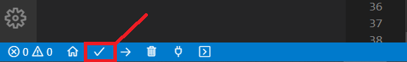 Go to the ESP IP address followed by /update and upload the new firmware as shown previously.
Next, we’ll see how to upload the files to the filesystem.
Go to the ESP IP address followed by /update and upload the new firmware as shown previously.
Next, we’ll see how to upload the files to the filesystem.
Update Filesystem
Under the project folder create a folder called data and paste the following HTML, CSS and JavaScript files (click on the links to download the files): HTML file: index.html CSS file: style.css JavaScript file: script.js After building the filesystem image, you should have a spiffs.bin file in the following path (or similar):
.pio/build/esp32doit-devkit-v1/
After building the filesystem image, you should have a spiffs.bin file in the following path (or similar):
.pio/build/esp32doit-devkit-v1/ That’s that file that you should upload to update the filesystem.
Go to your ESP IP address followed by/update.
Make sure you have the
After successfully uploading, click the
To see the web server working, you can connect 4 LEDs to your ESP32 on GPIOS: 2, 4, 12 and 14.
You should be able to control those outputs from the web server.
If you need to update something on your project, you just need to go to your ESP32 IP address followed by /update.
Congratulations! You’ve successfully uploaded files to the ESP32 filesystem using ElegantOTA.
That’s that file that you should upload to update the filesystem.
Go to your ESP IP address followed by/update.
Make sure you have the
After successfully uploading, click the
To see the web server working, you can connect 4 LEDs to your ESP32 on GPIOS: 2, 4, 12 and 14.
You should be able to control those outputs from the web server.
If you need to update something on your project, you just need to go to your ESP32 IP address followed by /update.
Congratulations! You’ve successfully uploaded files to the ESP32 filesystem using ElegantOTA.
Watch the Video Demonstration
Wrapping Up
In this tutorial, you’ve learned how to add OTA capabilities to your Async Web Servers using the AsyncElegantOTA library .
This library is super simple to use and allows you to upload new firmware or files to the filesystem effortlessly using a web page.
In our opinion, the AsyncElegantOTA library is one of the best options to handle OTA web updates.
We hope you’ve found this tutorial useful.
Learn everything you need to know about building web servers with the ESP32:
ESP32 Over-the-air (OTA) Programming – Web Updater Arduino IDE
Quick guide that shows how to do over-the-air (OTA) programming with the ESP32 using the OTA Web Updater in Arduino IDE.The OTA Web Updater allows you to update/upload new code to your ESP32 using a browser, without the need to make a serial connection between the ESP32 and your computer. OTA programming is useful when you need to update code to ESP32 boards that are not easily accessible.
The example we’ll show here works when the ESP32 and your browser are on your local network.
The only disadvantage of the OTA Web Updater is that you have to add the code for OTA in every sketch you upload, so that you’re able to use OTA in the future.
OTA programming is useful when you need to update code to ESP32 boards that are not easily accessible.
The example we’ll show here works when the ESP32 and your browser are on your local network.
The only disadvantage of the OTA Web Updater is that you have to add the code for OTA in every sketch you upload, so that you’re able to use OTA in the future.
How does OTA Web Updater Work?
The first sketch should be uploaded via serial port.
This sketch should contain the code to create the OTA Web Updater, so that you are able to upload code later using your browser.
The OTA Web Updater sketch creates a web server you can access to upload a new sketch via web browser.
Then, you need to implement OTA routines in every sketch you upload, so that you’re able to do the next updates/uploads over-the-air.
If you upload a code without a OTA routine you’ll no longer be able to access the web server and upload a new sketch over-the-air.
Prerequisites
Before proceeding with this tutorial you should have the ESP32 add-on installed in your Arduino IDE.
Follow one of the next tutorials to install the ESP32 on the Arduino IDE, if you haven’t already.
Installing the ESP32 Board in Arduino IDE (Windows instructions)
Installing the ESP32 Board in Arduino IDE (Mac and Linux instructions)
ESP32 OTA Web Updater
When you install the ESP32 add-on for the Arduino IDE, it will automatically install the ArduinoOTA library.
Go to  The following code should load.
/*
* OTAWebUpdater.ino Example from ArduinoOTA Library
* Rui Santos
* Complete Project Details https://randomnerdtutorials.com
*/
#include <WiFi.h>
#include <WiFiClient.h>
#include <WebServer.h>
#include <ESPmDNS.h>
#include <Update.h>
const char* host = "esp32";
const char* ssid = "REPLACE_WITH_YOUR_SSID";
const char* password = "REPLACE_WITH_YOUR_PASSWORD";
WebServer server(80);
/*
* Login page
*/
const char* loginIndex =
"<form name='loginForm'>"
"<table width='20%' bgcolor='A09F9F' align='center'>"
"<tr>"
"<td colspan=2>"
"<center><font size=4><b>ESP32 Login Page</b></font></center>"
"<br>"
"</td>"
"<br>"
"<br>"
"</tr>"
"<td>Username:</td>"
"<td><input type='text' size=25 name='userid'><br></td>"
"</tr>"
"<br>"
"<br>"
"<tr>"
"<td>Password:</td>"
"<td><input type='Password' size=25 name='pwd'><br></td>"
"<br>"
"<br>"
"</tr>"
"<tr>"
"<td><input type='submit' onclick='check(this.form)' value='Login'></td>"
"</tr>"
"</table>"
"</form>"
"<script>"
"function check(form)"
"{"
"if(form.userid.value=='admin' && form.pwd.value=='admin')"
"{"
"window.open('/serverIndex')"
"}"
"else"
"{"
" alert('Error Password or Username')/*displays error message*/"
"}"
"}"
"</script>";
/*
* Server Index Page
*/
const char* serverIndex =
"<script src='https://ajax.googleapis.com/ajax/libs/jquery/3.2.1/jquery.min.js'></script>"
"<form method='POST' action='#' enctype='multipart/form-data' id='upload_form'>"
"<input type='file' name='update'>"
"<input type='submit' value='Update'>"
"</form>"
"<div id='prg'>progress: 0%</div>"
"<script>"
"$('form').submit(function(e){"
"e.preventDefault();"
"var form = $('#upload_form')[0];"
"var data = new FormData(form);"
" $.ajax({"
"url: '/update',"
"type: 'POST',"
"data: data,"
"contentType: false,"
"processData:false,"
"xhr: function() {"
"var xhr = new window.XMLHttpRequest();"
"xhr.upload.addEventListener('progress', function(evt) {"
"if (evt.lengthComputable) {"
"var per = evt.loaded / evt.total;"
"$('#prg').html('progress: ' + Math.round(per*100) + '%');"
"}"
"}, false);"
"return xhr;"
"},"
"success:function(d, s) {"
"console.log('success!')"
"},"
"error: function (a, b, c) {"
"}"
"});"
"});"
"</script>";
/*
* setup function
*/
void setup(void) {
Serial.begin(115200);
// Connect to WiFi network
WiFi.begin(ssid, password);
Serial.println("");
// Wait for connection
while (WiFi.status() != WL_CONNECTED) {
delay(500);
Serial.print(".");
}
Serial.println("");
Serial.print("Connected to ");
Serial.println(ssid);
Serial.print("IP address: ");
Serial.println(WiFi.localIP());
/*use mdns for host name resolution*/
if (!MDNS.begin(host)) { //http://esp32.local
Serial.println("Error setting up MDNS responder!");
while (1) {
delay(1000);
}
}
Serial.println("mDNS responder started");
/*return index page which is stored in serverIndex */
server.on("/", HTTP_GET, []() {
server.sendHeader("Connection", "close");
server.send(200, "text/html", loginIndex);
});
server.on("/serverIndex", HTTP_GET, []() {
server.sendHeader("Connection", "close");
server.send(200, "text/html", serverIndex);
});
/*handling uploading firmware file */
server.on("/update", HTTP_POST, []() {
server.sendHeader("Connection", "close");
server.send(200, "text/plain", (Update.hasError()) ? "FAIL" : "OK");
ESP.restart();
}, []() {
HTTPUpload& upload = server.upload();
if (upload.status == UPLOAD_FILE_START) {
Serial.printf("Update: %s\n", upload.filename.c_str());
if (!Update.begin(UPDATE_SIZE_UNKNOWN)) { //start with max available size
Update.printError(Serial);
}
} else if (upload.status == UPLOAD_FILE_WRITE) {
/* flashing firmware to ESP*/
if (Update.write(upload.buf, upload.currentSize) != upload.currentSize) {
Update.printError(Serial);
}
} else if (upload.status == UPLOAD_FILE_END) {
if (Update.end(true)) { //true to set the size to the current progress
Serial.printf("Update Success: %u\nRebooting...\n", upload.totalSize);
} else {
Update.printError(Serial);
}
}
});
server.begin();
}
void loop(void) {
server.handleClient();
delay(1);
}
View raw code
You should change the following lines on the code to include your own network credentials:
const char* ssid = "";
const char* password = "";
The OTAWebUpdater example for the ESP32 creates an asynchronous web server where you can upload new code to your board without the need for a serial connection.
Upload the previous code to your ESP32 board.
Don’t forget to enter your network credentials and select the right board and serial port.
After uploading the code, open the Serial Monitor at a baud rate of 115200, press the ESP32 enable button, and you should get the ESP32 IP address:
The following code should load.
/*
* OTAWebUpdater.ino Example from ArduinoOTA Library
* Rui Santos
* Complete Project Details https://randomnerdtutorials.com
*/
#include <WiFi.h>
#include <WiFiClient.h>
#include <WebServer.h>
#include <ESPmDNS.h>
#include <Update.h>
const char* host = "esp32";
const char* ssid = "REPLACE_WITH_YOUR_SSID";
const char* password = "REPLACE_WITH_YOUR_PASSWORD";
WebServer server(80);
/*
* Login page
*/
const char* loginIndex =
"<form name='loginForm'>"
"<table width='20%' bgcolor='A09F9F' align='center'>"
"<tr>"
"<td colspan=2>"
"<center><font size=4><b>ESP32 Login Page</b></font></center>"
"<br>"
"</td>"
"<br>"
"<br>"
"</tr>"
"<td>Username:</td>"
"<td><input type='text' size=25 name='userid'><br></td>"
"</tr>"
"<br>"
"<br>"
"<tr>"
"<td>Password:</td>"
"<td><input type='Password' size=25 name='pwd'><br></td>"
"<br>"
"<br>"
"</tr>"
"<tr>"
"<td><input type='submit' onclick='check(this.form)' value='Login'></td>"
"</tr>"
"</table>"
"</form>"
"<script>"
"function check(form)"
"{"
"if(form.userid.value=='admin' && form.pwd.value=='admin')"
"{"
"window.open('/serverIndex')"
"}"
"else"
"{"
" alert('Error Password or Username')/*displays error message*/"
"}"
"}"
"</script>";
/*
* Server Index Page
*/
const char* serverIndex =
"<script src='https://ajax.googleapis.com/ajax/libs/jquery/3.2.1/jquery.min.js'></script>"
"<form method='POST' action='#' enctype='multipart/form-data' id='upload_form'>"
"<input type='file' name='update'>"
"<input type='submit' value='Update'>"
"</form>"
"<div id='prg'>progress: 0%</div>"
"<script>"
"$('form').submit(function(e){"
"e.preventDefault();"
"var form = $('#upload_form')[0];"
"var data = new FormData(form);"
" $.ajax({"
"url: '/update',"
"type: 'POST',"
"data: data,"
"contentType: false,"
"processData:false,"
"xhr: function() {"
"var xhr = new window.XMLHttpRequest();"
"xhr.upload.addEventListener('progress', function(evt) {"
"if (evt.lengthComputable) {"
"var per = evt.loaded / evt.total;"
"$('#prg').html('progress: ' + Math.round(per*100) + '%');"
"}"
"}, false);"
"return xhr;"
"},"
"success:function(d, s) {"
"console.log('success!')"
"},"
"error: function (a, b, c) {"
"}"
"});"
"});"
"</script>";
/*
* setup function
*/
void setup(void) {
Serial.begin(115200);
// Connect to WiFi network
WiFi.begin(ssid, password);
Serial.println("");
// Wait for connection
while (WiFi.status() != WL_CONNECTED) {
delay(500);
Serial.print(".");
}
Serial.println("");
Serial.print("Connected to ");
Serial.println(ssid);
Serial.print("IP address: ");
Serial.println(WiFi.localIP());
/*use mdns for host name resolution*/
if (!MDNS.begin(host)) { //http://esp32.local
Serial.println("Error setting up MDNS responder!");
while (1) {
delay(1000);
}
}
Serial.println("mDNS responder started");
/*return index page which is stored in serverIndex */
server.on("/", HTTP_GET, []() {
server.sendHeader("Connection", "close");
server.send(200, "text/html", loginIndex);
});
server.on("/serverIndex", HTTP_GET, []() {
server.sendHeader("Connection", "close");
server.send(200, "text/html", serverIndex);
});
/*handling uploading firmware file */
server.on("/update", HTTP_POST, []() {
server.sendHeader("Connection", "close");
server.send(200, "text/plain", (Update.hasError()) ? "FAIL" : "OK");
ESP.restart();
}, []() {
HTTPUpload& upload = server.upload();
if (upload.status == UPLOAD_FILE_START) {
Serial.printf("Update: %s\n", upload.filename.c_str());
if (!Update.begin(UPDATE_SIZE_UNKNOWN)) { //start with max available size
Update.printError(Serial);
}
} else if (upload.status == UPLOAD_FILE_WRITE) {
/* flashing firmware to ESP*/
if (Update.write(upload.buf, upload.currentSize) != upload.currentSize) {
Update.printError(Serial);
}
} else if (upload.status == UPLOAD_FILE_END) {
if (Update.end(true)) { //true to set the size to the current progress
Serial.printf("Update Success: %u\nRebooting...\n", upload.totalSize);
} else {
Update.printError(Serial);
}
}
});
server.begin();
}
void loop(void) {
server.handleClient();
delay(1);
}
View raw code
You should change the following lines on the code to include your own network credentials:
const char* ssid = "";
const char* password = "";
The OTAWebUpdater example for the ESP32 creates an asynchronous web server where you can upload new code to your board without the need for a serial connection.
Upload the previous code to your ESP32 board.
Don’t forget to enter your network credentials and select the right board and serial port.
After uploading the code, open the Serial Monitor at a baud rate of 115200, press the ESP32 enable button, and you should get the ESP32 IP address:
 Now, you can upload code to your ESP32 over-the-air using a browser on your local network.
To test the OTA Web Updater you can disconnect the ESP32 from your computer and power it using a power bank, for example (this is optional, we’re suggesting this to mimic a situation in which the ESP32 is not connected to your computer).
Now, you can upload code to your ESP32 over-the-air using a browser on your local network.
To test the OTA Web Updater you can disconnect the ESP32 from your computer and power it using a power bank, for example (this is optional, we’re suggesting this to mimic a situation in which the ESP32 is not connected to your computer).
Update New Code using OTA Web Updater
Open a browser in your network and enter the ESP32 IP address.
You should get the following:
 Enter the username and the password:

Preparing the New Sketch
When uploading a new sketch over-the-air, you need to keep in mind that you need to add code for OTA in your new sketch, so that you canalways overwrite any sketch with a new one in the future.
So, we recommend that you modify theOTAWebUpdater sketch to include your own code.
For learning purposes let’s upload a new code that blinks an LED (without delay).
Copy the following code to your Arduino IDE.
/*
* Rui Santos
* Complete Project Details https://randomnerdtutorials.com
*/
#include <WiFi.h>
#include <WiFiClient.h>
#include <WebServer.h>
#include <ESPmDNS.h>
#include <Update.h>
const char* host = "esp32";
const char* ssid = "REPLACE_WITH_YOUR_SSID";
const char* password = "REPLACE_WITH_YOUR_PASSWORD";
//variabls to blink without delay:
const int led = 2;
unsigned long previousMillis = 0; // will store last time LED was updated
const long interval = 1000; // interval at which to blink (milliseconds)
int ledState = LOW; // ledState used to set the LED
WebServer server(80);
/*
* Login page
*/
const char* loginIndex =
"<form name='loginForm'>"
"<table width='20%' bgcolor='A09F9F' align='center'>"
"<tr>"
"<td colspan=2>"
"<center><font size=4><b>ESP32 Login Page</b></font></center>"
"<br>"
"</td>"
"<br>"
"<br>"
"</tr>"
"<td>Username:</td>"
"<td><input type='text' size=25 name='userid'><br></td>"
"</tr>"
"<br>"
"<br>"
"<tr>"
"<td>Password:</td>"
"<td><input type='Password' size=25 name='pwd'><br></td>"
"<br>"
"<br>"
"</tr>"
"<tr>"
"<td><input type='submit' onclick='check(this.form)' value='Login'></td>"
"</tr>"
"</table>"
"</form>"
"<script>"
"function check(form)"
"{"
"if(form.userid.value=='admin' && form.pwd.value=='admin')"
"{"
"window.open('/serverIndex')"
"}"
"else"
"{"
" alert('Error Password or Username')/*displays error message*/"
"}"
"}"
"</script>";
/*
* Server Index Page
*/
const char* serverIndex =
"<script src='https://ajax.googleapis.com/ajax/libs/jquery/3.2.1/jquery.min.js'></script>"
"<form method='POST' action='#' enctype='multipart/form-data' id='upload_form'>"
"<input type='file' name='update'>"
"<input type='submit' value='Update'>"
"</form>"
"<div id='prg'>progress: 0%</div>"
"<script>"
"$('form').submit(function(e){"
"e.preventDefault();"
"var form = $('#upload_form')[0];"
"var data = new FormData(form);"
" $.ajax({"
"url: '/update',"
"type: 'POST',"
"data: data,"
"contentType: false,"
"processData:false,"
"xhr: function() {"
"var xhr = new window.XMLHttpRequest();"
"xhr.upload.addEventListener('progress', function(evt) {"
"if (evt.lengthComputable) {"
"var per = evt.loaded / evt.total;"
"$('#prg').html('progress: ' + Math.round(per*100) + '%');"
"}"
"}, false);"
"return xhr;"
"},"
"success:function(d, s) {"
"console.log('success!')"
"},"
"error: function (a, b, c) {"
"}"
"});"
"});"
"</script>";
/*
* setup function
*/
void setup(void) {
pinMode(led, OUTPUT);
Serial.begin(115200);
// Connect to WiFi network
WiFi.begin(ssid, password);
Serial.println("");
// Wait for connection
while (WiFi.status() != WL_CONNECTED) {
delay(500);
Serial.print(".");
}
Serial.println("");
Serial.print("Connected to ");
Serial.println(ssid);
Serial.print("IP address: ");
Serial.println(WiFi.localIP());
/*use mdns for host name resolution*/
if (!MDNS.begin(host)) { //http://esp32.local
Serial.println("Error setting up MDNS responder!");
while (1) {
delay(1000);
}
}
Serial.println("mDNS responder started");
/*return index page which is stored in serverIndex */
server.on("/", HTTP_GET, []() {
server.sendHeader("Connection", "close");
server.send(200, "text/html", loginIndex);
});
server.on("/serverIndex", HTTP_GET, []() {
server.sendHeader("Connection", "close");
server.send(200, "text/html", serverIndex);
});
/*handling uploading firmware file */
server.on("/update", HTTP_POST, []() {
server.sendHeader("Connection", "close");
server.send(200, "text/plain", (Update.hasError()) ? "FAIL" : "OK");
ESP.restart();
}, []() {
HTTPUpload& upload = server.upload();
if (upload.status == UPLOAD_FILE_START) {
Serial.printf("Update: %s\n", upload.filename.c_str());
if (!Update.begin(UPDATE_SIZE_UNKNOWN)) { //start with max available size
Update.printError(Serial);
}
} else if (upload.status == UPLOAD_FILE_WRITE) {
/* flashing firmware to ESP*/
if (Update.write(upload.buf, upload.currentSize) != upload.currentSize) {
Update.printError(Serial);
}
} else if (upload.status == UPLOAD_FILE_END) {
if (Update.end(true)) { //true to set the size to the current progress
Serial.printf("Update Success: %u\nRebooting...\n", upload.totalSize);
} else {
Update.printError(Serial);
}
}
});
server.begin();
}
void loop(void) {
server.handleClient();
delay(1);
//loop to blink without delay
unsigned long currentMillis = millis();
if (currentMillis - previousMillis >= interval) {
// save the last time you blinked the LED
previousMillis = currentMillis;
// if the LED is off turn it on and vice-versa:
ledState = not(ledState);
// set the LED with the ledState of the variable:
digitalWrite(led, ledState);
}
}
View raw code
As you can see, we’ve added the “blink without delay” code to the OTAWebUpdater code, so that we’re able to make updates later on.
After copying the code to your Arduino IDE, you should generate a .bin file.
Generate a .bin file in Arduino IDE
Save your sketch as LED_Web_Updater. To generate a .bin file from your sketch, go to A new file on the folder sketch should be created.
Go to
A new file on the folder sketch should be created.
Go to 
Upload a new sketch over-the-air to the ESP32
In your browser, on the ESP32 OTA Web Updater page, click the The ESP32 built-in LED should be blinking.
 Congratulations! You’ve uploaded a new code to your ESP32 over-the-air.
Wrapping Up
Over-the-air updates are useful to upload new code to your ESP32 board when it is not easily accessible.
The OTA Web Updater code creates a web server that you can access to upload new code to your ESP32 board using a web browser on your local network.
We hope you’ve found this article interesting.
If you like ESP32 you may also like:
SMART HOME with Raspberry Pi, ESP32, ESP8266 [eBook]
ESP32 Pinout Reference: Which GPIO pins should you use?
The ESP32 chip comes with 48 pins with multiple functions. Not all pins are exposed in all ESP32 development boards, and some pins cannot be used. There are many questions on how to use the ESP32 GPIOs. What pins should you use? What pins should you avoid using in your projects? This post aims to be a simple and easy-to-follow reference guide for the ESP32 GPIOs. The figure below illustrates the ESP-WROOM-32 pinout. You can use it as a reference if you’re using an

ESP32 Peripherals
The ESP32 peripherals include:
18 Analog-to-Digital Converter (ADC) channels
3 SPI interfaces
3 UART interfaces
2 I2C interfaces
16 PWM output channels
2 Digital-to-Analog Converters (DAC)
2 I2S interfaces
10Capacitive sensing GPIOs
The ADC (analog to digital converter) and DAC (digital to analog converter) features are assigned to specific static pins.
However, you can decide which pins are UART, I2C, SPI, PWM, etc – you just need to assign them in the code.
This is possible due to the ESP32 chip’s multiplexing feature.
Although you can define the pins properties on the software, there are pins assigned by default as shown in the following figure (this is an example for the ESP32 DEVKIT V1 DOIT board with 36 pins – the pin location can change depending on the manufacturer).
Additionally, there are pins with specific features that make them suitable or not for a particular project.
The following table shows what pins are best to use as inputs, outputs and which ones you need to be cautious.
The pins highlighted in green are OK to use.
The ones highlighted in yellow are OK to use, but you need to pay attention because they may have an unexpected behavior mainly at boot.
The pins highlighted in red are not recommended to use as inputs or outputs.
| pulled up | OK | outputs PWM signal at boot, must be LOW to enter flashing mode | |
| TX pin | OK | debug output at boot | |
| OK | OK | connected to on-board LED, must be left floating or LOW to enter flashing mode | |
| OK | RX pin | HIGH at boot | |
| OK | OK | ||
| OK | OK | outputs PWM signal at boot, strapping pin | |
| x | x | connected to the integrated SPI flash | |
| x | x | connected to the integrated SPI flash | |
| x | x | connected to the integrated SPI flash | |
| x | x | connected to the integrated SPI flash | |
| x | x | connected to the integrated SPI flash | |
| x | x | connected to the integrated SPI flash | |
| OK | OK | boot fails if pulled high, strapping pin | |
| OK | OK | ||
| OK | OK | outputs PWM signal at boot | |
| OK | OK | outputs PWM signal at boot, strapping pin | |
| OK | OK | ||
| OK | OK | ||
| OK | OK | ||
| OK | OK | ||
| OK | OK | ||
| OK | OK | ||
| OK | OK | ||
| OK | OK | ||
| OK | OK | ||
| OK | OK | ||
| OK | OK | ||
| OK | OK | ||
| OK | input only | ||
| OK | input only | ||
| OK | input only | ||
| OK | input only |
Input only pins
GPIOs 34 to 39 are GPIs – input only pins. These pins don’t have internal pull-up or pull-down resistors. They can’t be used as outputs, so use these pins only as inputs: GPIO 34 GPIO 35 GPIO 36 GPIO 39SPI flash integrated on the ESP-WROOM-32
GPIO 6 to GPIO 11 are exposed in some ESP32 development boards. However, these pins are connected to the integrated SPI flash on the ESP-WROOM-32 chip and are not recommended for other uses. So, don’t use these pins in your projects: GPIO 6 (SCK/CLK) GPIO 7 (SDO/SD0) GPIO 8 (SDI/SD1) GPIO 9 (SHD/SD2) GPIO 10 (SWP/SD3) GPIO 11 (CSC/CMD)Capacitive touch GPIOs
The ESP32 has 10 internal capacitive touch sensors. These can sense variations in anything that holds an electrical charge, like the human skin. So they can detect variations induced when touching the GPIOs with a finger. These pins can be easily integrated into capacitive pads and replace mechanical buttons. The capacitive touch pins can also be used to wake up the ESP32 from deep sleep . Those internal touch sensors are connected to these GPIOs: T0 (GPIO 4) T1 (GPIO 0) T2 (GPIO 2) T3 (GPIO 15) T4 (GPIO 13) T5 (GPIO 12) T6 (GPIO 14) T7 (GPIO 27) T8 (GPIO 33) T9 (GPIO 32)Analog to Digital Converter (ADC)
The ESP32 has 18 x 12 bits ADC input channels (while the ESP8266 only has 1x 10 bits ADC ).These are the GPIOs that can be used as ADC and respective channels: ADC1_CH0 (GPIO 36) ADC1_CH2(GPIO 37) ADC1_CH2 (GPIO 38) ADC1_CH3 (GPIO 39) ADC1_CH4 (GPIO 32) ADC1_CH5 (GPIO 33) ADC1_CH6 (GPIO 34) ADC1_CH7 (GPIO 35) ADC2_CH0 (GPIO 4) ADC2_CH2(GPIO 0) ADC2_CH2 (GPIO 2) ADC2_CH3 (GPIO 15) ADC2_CH4 (GPIO 13) ADC2_CH5 (GPIO 12) ADC2_CH6 (GPIO 14) ADC2_CH7 (GPIO 27) ADC2_CH8 (GPIO 25) ADC2_CH9 (GPIO 26)
View source
Digital to Analog Converter (DAC)
There are 2 x 8 bits DAC channels on the ESP32 to convert digital signals into analog voltage signal outputs. These are the DAC channels: DAC1 (GPIO25) DAC2 (GPIO26)RTC GPIOs
There is RTC GPIO support on the ESP32. The GPIOs routed to the RTC low-power subsystem can be used when the ESP32 is in deep sleep. These RTC GPIOs can be used to wake up the ESP32 from deep sleep when the Ultra Low Power (ULP) co-processor is running. The following GPIOs can be used as an external wake up source . RTC_GPIO0 (GPIO36) RTC_GPIO3 (GPIO39) RTC_GPIO4 (GPIO34) RTC_GPIO5 (GPIO35) RTC_GPIO6 (GPIO25) RTC_GPIO7 (GPIO26) RTC_GPIO8 (GPIO33) RTC_GPIO9 (GPIO32) RTC_GPIO10 (GPIO4) RTC_GPIO11 (GPIO0) RTC_GPIO12 (GPIO2) RTC_GPIO13 (GPIO15) RTC_GPIO14 (GPIO13) RTC_GPIO15 (GPIO12) RTC_GPIO16 (GPIO14) RTC_GPIO17 (GPIO27)PWM
The ESP32 LED PWM controller has 16 independent channels that can be configured to generate PWM signals with different properties. All pins that can act as outputs can be used as PWM pins (GPIOs 34 to 39 can’t generate PWM). To set a PWM signal, you need to define these parameters in the code: Signal’s frequency; Duty cycle; PWM channel; GPIO where you want to output the signal.I2C
The ESP32 has two I2C channels and any pin can be set as SDA or SCL. When using the ESP32 with the Arduino IDE, the default I2C pins are: GPIO 21 (SDA) GPIO 22 (SCL) If you want to use other pins when using the wire library, you just need to call: Wire.begin(SDA, SCL);SPI
By default, the pin mapping for SPI is:| GPIO 23 | GPIO 19 | GPIO 18 | GPIO 5 | |
| GPIO 13 | GPIO 12 | GPIO 14 | GPIO 15 |
Interrupts
All GPIOs can be configured as interrupts.Strapping Pins
The ESP32 chip has the following strapping pins: GPIO 0 (must be LOW to enter boot mode) GPIO 2 (must be floating or LOW during boot) GPIO 4 GPIO 5 (must be HIGH during boot) GPIO 12 (must be LOW during boot) GPIO 15 (must be HIGH during boot) These are used to put the ESP32 into bootloader or flashing mode. On most development boards with built-in USB/Serial, you don’t need to worry about the state of these pins. The board puts the pins in the right state for flashing or boot mode. More information on the ESP32 Boot Mode Selection can be found here . However, if you have peripherals connected to those pins, you may have trouble trying to upload new code, flashing the ESP32 with new firmware, or resetting the board. If you have some peripherals connected to the strapping pins and you are getting trouble uploading code or flashing the ESP32, it may be because those peripherals are preventing the ESP32 from entering the right mode. Read the Boot Mode Selection documentation to guide you in the right direction. After resetting, flashing, or booting, those pins work as expected.Pins HIGH at Boot
Some GPIOs change their state to HIGH or output PWM signals at boot or reset. This means that if you have outputs connected to these GPIOs you may get unexpected results when the ESP32 resets or boots. GPIO 1 GPIO 3 GPIO 5 GPIO 6 to GPIO 11 (connected to the ESP32 integrated SPI flash memory – not recommended to use). GPIO 14 GPIO 15Enable (EN)
Enable (EN) is the 3.3V regulator’s enable pin. It’s pulled up, so connect to ground to disable the 3.3V regulator. This means that you can use this pin connected to a pushbutton to restart your ESP32, for example.GPIO current drawn
The absolute maximum current drawn per GPIO is 40mA according to the “Recommended Operating Conditions” section in the ESP32 datasheet.ESP32 Built-In Hall Effect Sensor
The ESP32 also features a built-in hall effect sensor that detects changes in the magnetic field in its surroundings.Wrapping Up
We hope you’ve found thisreference guide for the ESP32 GPIOs useful.
If you have more tips about the ESP32 GPIOs, please share by writing a comment down below.
If you’re just getting started with the ESP32, we have some great content to get started:
ESP32 with PIR Motion Sensor using Interrupts and Timers
This tutorial shows how to detect motion with the ESP32 using a PIR motion sensor. In this example, when motion is detected (an interrupt is triggered), the ESP32 starts a timer and turns an LED on for a predefined number of seconds. When the timer finishes counting down, the LED is automatically turned off. With this example we’ll also explore two important concepts: interrupts and timers.
Before proceeding with this tutorial you should have the ESP32 add-on installed in your Arduino IDE.
Follow one of the following tutorials to install the ESP32 on the Arduino IDE, if you haven’t already.
Installing the ESP32 Board in Arduino IDE (Windows instructions)
Installing the ESP32 Board in Arduino IDE (Mac and Linux instructions)
With this example we’ll also explore two important concepts: interrupts and timers.
Before proceeding with this tutorial you should have the ESP32 add-on installed in your Arduino IDE.
Follow one of the following tutorials to install the ESP32 on the Arduino IDE, if you haven’t already.
Installing the ESP32 Board in Arduino IDE (Windows instructions)
Installing the ESP32 Board in Arduino IDE (Mac and Linux instructions)
Watch the Video Tutorial and Project Demo
This tutorial is available in video format (watch below) and in written format (continue reading).
Parts Required
To follow this tutorial you need the following parts
ESP32 DOIT DEVKIT V1 Board – read ESP32 Development Boards Review and Comparison
Mini PIR motion sensor (AM312) or PIR motion sensor (HC-SR501)
5mm LED
330 Ohm resistor
Jumper wires
Breadboard
You can use the preceding links or go directly to MakerAdvisor.com/tools to find all the parts for your projects at the best price!
Introducing Interrupts
To trigger an event with a PIR motion sensor, you use interrupts.
Interrupts are useful for making things happen automatically in microcontroller programs, and can help solve timing problems.
With interrupts you don’t need to constantly check the current value of a pin.
With interrupts, when a change is detected, an event is triggered (a function is called).
To set an interrupt in the Arduino IDE, you use the 
Introducing Timers
In this example we’ll also introduce timers.
We want the LED to stay on for a predetermined number of seconds after motion is detected.
Instead of using a delay() function that blocks your code and doesn’t allow you to do anything else for a determined number of seconds, we should use a timer.

The delay() function
You should be familiar with the delay() function as it is widely used. This function is pretty straightforward to use. It accepts a single int number as an argument. This number represents the time in milliseconds the program has to wait until moving on to the next line of code. delay(time in milliseconds) When you do delay(1000) your program stops on that line for 1 second. delay() is a blocking function. Blocking functions prevent a program from doing anything else until that particular task is completed. If you need multiple tasks to occur at the same time, you cannot use delay(). For most projects you should avoid using delays and use timers instead.The millis() function
Using a function called millis() you can return the number of milliseconds that have passed since the program first started. millis() Why is that function useful? Because by using some math, you can easily verify how much time has passed without blocking your code.Blinking an LED with millis()
The following snippet of code shows how you can use the millis() function to create a blink LED project. It turns an LED on for 1000 milliseconds, and then turns it off. /********* Rui Santos Complete project details at https://randomnerdtutorials.com *********/ // constants won't change. Used here to set a pin number : const int ledPin = 26; // the number of the LED pin // Variables will change : int ledState = LOW; // ledState used to set the LED // Generally, you should use "unsigned long" for variables that hold time // The value will quickly become too large for an int to store unsigned long previousMillis = 0; // will store last time LED was updated // constants won't change : const long interval = 1000; // interval at which to blink (milliseconds) void setup() { // set the digital pin as output: pinMode(ledPin, OUTPUT); } void loop() { // here is where you'd put code that needs to be running all the time. // check to see if it's time to blink the LED; that is, if the // difference between the current time and last time you blinked // the LED is bigger than the interval at which you want to // blink the LED. unsigned long currentMillis = millis(); if (currentMillis - previousMillis >= interval) { // save the last time you blinked the LED previousMillis = currentMillis; // if the LED is off turn it on and vice-versa: if (ledState == LOW) { ledState = HIGH; } else { ledState = LOW; } // set the LED with the ledState of the variable: digitalWrite(ledPin, ledState); } } View raw codeHow the code works
Let’s take a closer look at this blink sketch that works without a delay() function (it uses the millis() function instead). Basically, this code subtracts the previous recorded time (previousMillis) from the current time (currentMillis). If the remainder is greater than the interval (in this case, 1000 milliseconds), the program updates the previousMillis variable to the current time, and either turns the LED on or off. if (currentMillis - previousMillis >= interval) { // save the last time you blinked the LED previousMillis = currentMillis; (...) Because this snippet is non-blocking, any code that’s located outside of that first if statement should work normally. You should now be able to understand that you can add other tasks to your loop() function and your code will still be blinking the LED every one second. You can upload this code to your ESP32 and assemble the following schematic diagram to test it and modify the number of milliseconds to see how it works.
ESP32 with PIR Motion Sensor
After understanding these concepts: interrupts and timers, let’s continue with the project.
Schematic
The circuit we’ll build is easy to assemble, we’ll be using an LED with a resistor. The LED is connected to GPIO 26. We’ll be using the Mini AM312 PIR Motion Sensor that operates at 3.3V. It will be connected to GPIO 27. Simply follow the next schematic diagram.

Uploading the Code
After wiring the circuit as shown in the schematic diagram, copy the code provided to your Arduino IDE. You can upload the code as it is, or you can modify the number of seconds the LED is lit after detecting motion. Simply change the timeSeconds variable with the number of seconds you want. /********* Rui Santos Complete project details at https://randomnerdtutorials.com *********/ #define timeSeconds 10 // Set GPIOs for LED and PIR Motion Sensor const int led = 26; const int motionSensor = 27; // Timer: Auxiliary variables unsigned long now = millis(); unsigned long lastTrigger = 0; boolean startTimer = false; boolean motion = false; // Checks if motion was detected, sets LED HIGH and starts a timer void IRAM_ATTR detectsMovement() { digitalWrite(led, HIGH); startTimer = true; lastTrigger = millis(); } void setup() { // Serial port for debugging purposes Serial.begin(115200); // PIR Motion Sensor mode INPUT_PULLUP pinMode(motionSensor, INPUT_PULLUP); // Set motionSensor pin as interrupt, assign interrupt function and set RISING mode attachInterrupt(digitalPinToInterrupt(motionSensor), detectsMovement, RISING); // Set LED to LOW pinMode(led, OUTPUT); digitalWrite(led, LOW); } void loop() { // Current time now = millis(); if((digitalRead(led) == HIGH) && (motion == false)) { Serial.println("MOTION DETECTED!!!"); motion = true; } // Turn off the LED after the number of seconds defined in the timeSeconds variable if(startTimer && (now - lastTrigger > (timeSeconds*1000))) { Serial.println("Motion stopped..."); digitalWrite(led, LOW); startTimer = false; motion = false; } } View raw codeHow the Code Works
Let’s take a look at the code. Start by assigning two GPIO pins to the led and motionSensor variables. // Set GPIOs for LED and PIR Motion Sensor const int led = 26; const int motionSensor = 27; Then, create variables that will allow you set a timer to turn the LED off after motion is detected. // Timer: Auxiliar variables long now = millis(); long lastTrigger = 0; boolean startTimer = false; The now variable holds the current time. The lastTrigger variable holds the time when the PIR sensor detects motion. The startTimer is a boolean variable that starts the timer when motion is detected.setup()
In the setup(), start by initializing the Serial port at 115200 baud rate. Serial.begin(115200); Set the PIR Motion sensor as an INPUT PULLUP. pinMode(motionSensor, INPUT_PULLUP); To set the PIR sensor pin as an interrupt, use the attachInterrupt() function as described earlier. attachInterrupt(digitalPinToInterrupt(motionSensor), detectsMovement, RISING); The pin that will detect motion is GPIO 27 and it will call the function detectsMovement() on RISING mode. The LED is an OUTPUT whose state starts at LOW. pinMode(led, OUTPUT); digitalWrite(led, LOW);loop()
The loop() function is constantly running over and over again. In every loop, the now variable is updated with the current time. now = millis(); Nothing else is done in the loop(). But, when motion is detected, the detectsMovement() function is called because we’ve set an interrupt previously on the setup(). The detectsMovement() function prints a message in the Serial Monitor, turns the LED on, sets the startTimer boolean variable to true and updates the lastTrigger variable with the current time. void IRAM_ATTR detectsMovement() { Serial.println("MOTION DETECTED!!!"); digitalWrite(led, HIGH); startTimer = true; lastTrigger = millis(); }Demonstration
Upload the code to your ESP32 board.
Make sure you have the right board and COM port selected.
Open the Serial Monitor at a baud rate of 115200.
Move your hand in front of the PIR sensor.
The LED should turn on, and a message is printed in the Serial Monitor saying “MOTION DETECTED!!!”.
After 10 seconds the LED should turn off.

Wrapping Up
To wrap up, interrupts are used to detect a change in the GPIO state without the need to constantly read the current GPIO value.
With interrupts, when a change is detected, a function is triggered.
You’ve also learned how to set a simple timer that allows you to check if a predefined number of seconds have passed without having to block your code.
We have other tutorials related with ESP32 that you may also like:
ESP32 Web Server – Arduino IDE
ESP32 Data Logging Temperature to MicroSD Card
How to Use I2C LCD with ESP32 on Arduino IDE
ESP32 vs ESP8266 – Pros and Cons
This is an excerpt from our course: Learn ESP32 with Arduino IDE .
If you like ESP32 and you want to learn more, we recommend enrolling in Learn ESP32 with Arduino IDE course .
ESP32 Plot Sensor Readings in Charts (Multiple Series)
This project shows how to build a web server with the ESP32 to plot sensor readings in charts with multiple series. As an example, we’ll plot sensor readings from four different DS18B20 temperature sensors on the same chart. You can modify the project to plot any other data. To build the charts, we’ll use the Highcharts JavaScript library. We have a similar tutorial for the ESP8266 NodeMCU board:
ESP8266 NodeMCU Plot Sensor Readings in Charts (Multiple Series)
We have a similar tutorial for the ESP8266 NodeMCU board:
ESP8266 NodeMCU Plot Sensor Readings in Charts (Multiple Series)
Project Overview
This project will build a web server with the ESP32 that displays temperature readings from four DS18B20 temperature sensors on the same chart—chart with multiple series.
The chart displays a maximum of 40 data points for each series, and new readings are added every 30 seconds.
You can change these values in your code.

DS18B20 Temperature Sensor
The DS18B20 temperature sensor is a one-wire digital temperature sensor. This means that it just requires one data line to communicate with your microcontroller.
Each sensor has a unique 64-bit serial number, which means you can connect multiple sensors to the same GPIO—as we’ll do in this tutorial.
Learn more about the DS18B20 temperature sensor:
ESP32 DS18B20 Temperature Sensor with Arduino IDE (Single, Multiple, Web Server)
ESP32 with Multiple DS18B20 Temperature Sensors
Server-Sent Events
The readings are updated automatically on the web page using Server-Sent Events (SSE). To learn more about SSE, you can read:
ESP32 Web Server using Server-Sent Events (Update Sensor Readings Automatically)
To learn more about SSE, you can read:
ESP32 Web Server using Server-Sent Events (Update Sensor Readings Automatically)
Files Saved on the Filesystem
To keep our project better organized and easier to understand, we’ll save the HTML, CSS, and JavaScript files to build the web page on the board’s filesystem (SPIFFS). Learn more about building a web server with files saved on the filesystem: ESP32 Web Server using SPIFFS (SPI Flash File System)Prerequisites
Make sure you check all the prerequisites in this section before continuing with the project.
1.Install ESP32 Board in Arduino IDE
We’ll program the ESP32 using Arduino IDE. So, you must have the ESP32 add-on installed. Follow the next tutorial if you haven’t already: Installing ESP32 Board in Arduino IDE (Windows, Mac OS X, Linux) If you want to use VS Code with the PlatformIO extension, follow the next tutorial instead to learn how to program the ESP32: Getting Started with VS Code and PlatformIO IDE for ESP32 and ESP8266 (Windows, Mac OS X, Linux Ubuntu)2.Filesystem Uploader Plugin
To upload the HTML, CSS, and JavaScript files to the ESP32 flash memory (SPIFFS), we’ll use a plugin for Arduino IDE:3.Installing Libraries
To build this project, you need to install the following libraries: OneWire (by Paul Stoffregen) (Arduino Library Manager); DallasTemperature (Arduino Library Manager); Arduino_JSON library by Arduino version 0.1.0 (Arduino Library Manager) ESPAsyncWebServer (.zip folder); AsyncTCP (.zip folder). You can install the first two libraries using the Arduino Library Manager. Go toInstalling Libraries (VS Code + PlatformIO)
If you’re programming the ESP32 using PlatformIO, you should add the following lines on the platformio.ini file to include the libraries (also change the Serial Monitor speed to 115200): monitor_speed = 115200 lib_deps = ESP Async WebServer arduino-libraries/Arduino_JSON @ 0.1.0 milesburton/DallasTemperature@^3.9.1 paulstoffregen/OneWire@^2.3.5Parts Required
To follow this tutorial you need the following parts:
ESP32 (read Best ESP32 development boards )
4x DS18B20 temperature sensor (one or multiple sensors) – waterproof version
4.7k Ohm resistor
Jumper wires
Breadboard
If you don’t have four DS18B20 sensors, you can use three or two.
Alternatively, you can also use other sensors (you need to modify the code) or data from any other source (for example, sensor readings received via MQTT, ESP-NOW, or random values—to experiment with this project…)
Schematic Diagram
Wire four DS18B20 sensors to your board.
 Recommended reading: ESP32 Pinout Reference: Which GPIO pins should you use?
Getting the DS18B20 Sensors’ Addresses
Each DS18B20 temperature sensor has an assigned serial number. First, you need to find that number to label each sensor accordingly. You need to do this so that later you know from which sensor you’re reading the temperature. Upload the following code to the ESP32. Make sure you have the right board and COM port selected. /* * Rui Santos * Complete Project Details https://randomnerdtutorials.com */ #include <OneWire.h> // Based on the OneWire library example OneWire ds(4); //data wire connected to GPIO 4 void setup(void) { Serial.begin(115200); } void loop(void) { byte i; byte addr[8]; if (!ds.search(addr)) { Serial.println(" No more addresses."); Serial.println(); ds.reset_search(); delay(250); return; } Serial.print(" ROM ="); for (i = 0; i < 8; i++) { Serial.write(' '); Serial.print(addr[i], HEX); } } View raw code Wire just one sensor at a time to find its address (or successively add a new sensor) so that you’re able to identify each one by its address. Then, you can add a physical label to each sensor. Open the Serial Monitor at a baud rate of 115200, press the on-board RST/EN button and you should get something as follows (but with different addresses): Untick the “
Organizing Your Files
To keep the project organized and make it easier to understand, we’ll create four files to build the web server:
 You should save the HTML, CSS, and JavaScript files inside a folder called
HTML File
Copy the following to the index.html file. <!-- Complete project details: https://randomnerdtutorials.com/esp32-plot-readings-charts-multiple/ --> <!DOCTYPE html> <html> <head> <title>ESP IOT DASHBOARD</title> <meta name="viewport" content="width=device-width, initial-scale=1"> <link rel="stylesheet" type="text/css" href="style.css"> <script src="https://code.highcharts.com/highcharts.js"></script> </head> <body> <div> <h1>ESP WEB SERVER CHARTS</h2> </div> <div> <div> <div> <p>Temperature Chart</p> <div></div> </div> </div> </div> <script src="script.js"></script> </body> </html> View raw code The HTML file for this project is very simple. It includes the JavaScript Highcharts library in the head of the HTML file: <script src="https://code.highcharts.com/highcharts.js"></script> There is a <div> section with the id chart-temperature where we’ll render our chart later on. <div></div>CSS File
Copy the following styles to your style.css file.
/* Complete project details: https://randomnerdtutorials.com/esp32-plot-readings-charts-multiple/ */
html {
font-family: Arial, Helvetica, sans-serif;
display: inline-block;
text-align: center;
}
h2{
font-size: 1.8rem;
color: white;
}
p {
font-size: 1.4rem;
}
.topnav {
overflow: hidden;
background-color: #0A1128;
}
body {
margin: 0;
}
.content {
padding: 5%;
}
.card-grid {
max-width: 1200px;
margin: 0 auto;
display: grid;
grid-gap: 2rem;
grid-template-columns: repeat(auto-fit, minmax(200px, 1fr));
}
.card {
background-color: white;
box-shadow: 2px 2px 12px 1px rgba(140,140,140,.5);
}
.card-title {
font-size: 1.2rem;
font-weight: bold;
color: #034078
}
.chart-container {
padding-right: 5%;
padding-left: 5%;
}
View raw code
JavaScript File (creating the charts)
Copy the following to thescript.jsfile.
Here’s a list of what this code does:
initializing the event source protocol;
adding an event listener for the new_readings event;
creating the chart;
getting the latest sensor readings from the new_readings event and plot them in the chart;
making an HTTP GET request for the current sensor readings when you access the web page for the first time.
// Complete project details: https://randomnerdtutorials.com/esp32-plot-readings-charts-multiple/
// Get current sensor readings when the page loads
window.addEventListener('load', getReadings);
// Create Temperature Chart
var chartT = new Highcharts.Chart({
chart:{
renderTo:'chart-temperature'
},
series: [
{
name: 'Temperature #1',
type: 'line',
color: '#101D42',
marker: {
symbol: 'circle',
radius: 3,
fillColor: '#101D42',
}
},
{
name: 'Temperature #2',
type: 'line',
color: '#00A6A6',
marker: {
symbol: 'square',
radius: 3,
fillColor: '#00A6A6',
}
},
{
name: 'Temperature #3',
type: 'line',
color: '#8B2635',
marker: {
symbol: 'triangle',
radius: 3,
fillColor: '#8B2635',
}
},
{
name: 'Temperature #4',
type: 'line',
color: '#71B48D',
marker: {
symbol: 'triangle-down',
radius: 3,
fillColor: '#71B48D',
}
},
],
title: {
text: undefined
},
xAxis: {
type: 'datetime',
dateTimeLabelFormats: { second: '%H:%M:%S' }
},
yAxis: {
title: {
text: 'Temperature Celsius Degrees'
}
},
credits: {
enabled: false
}
});
//Plot temperature in the temperature chart
function plotTemperature(jsonValue) {
var keys = Object.keys(jsonValue);
console.log(keys);
console.log(keys.length);
for (var i = 0; i < keys.length; i++){
var x = (new Date()).getTime();
console.log(x);
const key = keys[i];
var y = Number(jsonValue[key]);
console.log(y);
if(chartT.series[i].data.length > 40) {
chartT.series[i].addPoint([x, y], true, true, true);
} else {
chartT.series[i].addPoint([x, y], true, false, true);
}
}
}
// Function to get current readings on the webpage when it loads for the first time
function getReadings(){
var xhr = new XMLHttpRequest();
xhr.onreadystatechange = function() {
if (this.readyState == 4 && this.status == 200) {
var myObj = JSON.parse(this.responseText);
console.log(myObj);
plotTemperature(myObj);
}
};
xhr.open("GET", "/readings", true);
xhr.send();
}
if (!!window.EventSource) {
var source = new EventSource('/events');
source.addEventListener('open', function(e) {
console.log("Events Connected");
}, false);
source.addEventListener('error', function(e) {
if (e.target.readyState != EventSource.OPEN) {
console.log("Events Disconnected");
}
}, false);
source.addEventListener('message', function(e) {
console.log("message", e.data);
}, false);
source.addEventListener('new_readings', function(e) {
console.log("new_readings", e.data);
var myObj = JSON.parse(e.data);
console.log(myObj);
plotTemperature(myObj);
}, false);
}
View raw code
Get Readings
When you access the web page for the first time, we’ll request the server to get the current sensor readings. Otherwise, we would have to wait for new sensor readings to arrive (via Server-Sent Events), which can take some time depending on the interval that you set on the server. Add an event listener that calls the getReadings function when the web page loads. // Get current sensor readings when the page loads window.addEventListener('load', getReadings); The window object represents an open window in a browser. The addEventListener() method sets up a function to be called when a certain event happens. In this case, we’ll call the getReadings function when the page loads (‘load’) to get the current sensor readings. Now, let’s take a look at the getReadings function. Create a new XMLHttpRequest object. Then, send a GET request to the server on the /readings URL using the open() and send() methods. function getReadings() { var xhr = new XMLHttpRequest(); xhr.open("GET", "/readings", true); xhr.send(); } When we send that request, the ESP will send a response with the required information. So, we need to handle what happens when we receive the response. We’ll use the onreadystatechange property that defines a function to be executed when the readyState property changes. The readyState property holds the status of the XMLHttpRequest. The response of the request is ready when the readyState is 4, and the status is 200. readyState = 4 means that the request finished and the response is ready; status = 200 means “OK” So, the request should look something like this: function getStates(){ var xhr = new XMLHttpRequest(); xhr.onreadystatechange = function() { if (this.readyState == 4 && this.status == 200) { … DO WHATEVER YOU WANT WITH THE RESPONSE … } }; xhr.open("GET", "/states", true); xhr.send(); } The response sent by the ESP is the following text in JSON format. { "sensor1" : "25", "sensor2" : "21", "sensor3" : "22", "sensor4" : "23" } We need to convert the JSON string into a JSON object using the parse() method. The result is saved on the myObj variable. var myObj = JSON.parse(this.responseText); The myObj varible is a JSON object that contains all the temperature readings. We want to plot those readings on the same chart. For that, we’ve created a function called plotTemperature() that plots the temperatures stored in a JSON object on a chart. plotTemperature(myObj); Here’s the complete getReadings() function. function getReadings(){ var xhr = new XMLHttpRequest(); xhr.onreadystatechange = function() { if (this.readyState == 4 && this.status == 200) { var myObj = JSON.parse(this.responseText); console.log(myObj); plotTemperature(myObj); } }; xhr.open("GET", "/readings", true); xhr.send(); }Creating the Chart
The following lines create the charts with multiple series. // Create Temperature Chart var chartT = new Highcharts.Chart({ chart:{ renderTo:'chart-temperature' }, series: [ { name: 'Temperature #1', type: 'line', color: '#101D42', marker: { symbol: 'circle', radius: 3, fillColor: '#101D42', } }, { name: 'Temperature #2', type: 'line', color: '#00A6A6', marker: { symbol: 'square', radius: 3, fillColor: '#00A6A6', } }, { name: 'Temperature #3', type: 'line', color: '#8B2635', marker: { symbol: 'triangle', radius: 3, fillColor: '#8B2635', } }, { name: 'Temperature #4', type: 'line', color: '#71B48D', marker: { symbol: 'triangle-down', radius: 3, fillColor: '#71B48D', } }, ], title: { text: undefined }, xAxis: { type: 'datetime', dateTimeLabelFormats: { second: '%H:%M:%S' } }, yAxis: { title: { text: 'Temperature Celsius Degrees' } }, credits: { enabled: false } }); To create a new chart, use the new Highcharts.Chart() method and pass as argument the chart properties. var chartT = new Highcharts.Chart({ In the next line, define where you want to put the chart. In our example, we want to place it in the HTML element with the chart-temperature id—see the . chart:{ renderTo:'chart-temperature' }, Then, define the options for the series. The following lines create the first series: series: [ { name: 'Temperature #1', type: 'line', color: '#101D42', marker: { symbol: 'circle', radius: 3, fillColor: '#101D42', } The name property defines the series name. The type property defines the type of chart—in this case, we want to build a line chart. The color refers to the color of the line—you can change it to whatever color you desire. Next, define the marker properties. You can choose from several default symbols—square, circle, diamond, triangle, triangle-down. You can also create your own symbols. The radius refers to the size of the marker, and the fillColor refers to the color of the marker. There are other properties you can use to customize the marker— learn more . marker: { symbol: 'circle', radius: 3, fillColor: '#101D42', } Creating the other series is similar, but we’ve chosen different names, markers and colors. There are many other options you can use to customize your series— check the documentation about plotOptions . You can also define the chart title—in this case, as we’ve already defined a title for the chart in a heading of the HTML file, we will not set the title here. The title is displayed by default, so we must set it to undefined. title: { text: undefined }, Define the properties for the X axis—this is the axis where we’ll display data and time. Check more options to customize the X axis . xAxis: { type: 'datetime', dateTimeLabelFormats: { second: '%H:%M:%S' } }, We set the title for the y axis. See all available properties for the y axis . yAxis: { title: { text: 'Temperature Celsius Degrees' } }Time Zone
If, for some reason, after building the project, the charts are not showing the right time zone, add the following lines to the JavaScript file after the second line: Highcharts.setOptions({ time: { timezoneOffset: -60 //Add your time zone offset here in minutes } }); The charts will show the time in UTC. If you want it to display in your timezone, you must set the useUTC parameter (which is a time parameter) as false: time:{ useUTC: false }, So, add that when creating the chart as follows: var chart = new Highcharts.Chart({ time:{ useUTC: false }, (…) To learn more about this property, check this link on the documentation: https://api.highcharts.com/highcharts/time.useUTC Finally, set the credits option to false to hide the credits of the Highcharts library. credits: { enabled: false }Plot Temperatures
We’ve created the plotTemperature() function that accepts as an argument a JSON object with the temperature readings we want to plot. //Plot temperature in the temperature chart function plotTemperature(jsonValue) { var keys = Object.keys(jsonValue); console.log(keys); console.log(keys.length); for (var i = 0; i < keys.length; i++){ var x = (new Date()).getTime(); console.log(x); const key = keys[i]; var y = Number(jsonValue[key]); console.log(y); if(chartT.series[i].data.length > 40) { chartT.series[i].addPoint([x, y], true, true, true); } else { chartT.series[i].addPoint([x, y], true, false, true); } } } First, we get the keys of our JSON object and save them on the keys variable. This allows us to go through all the keys in the object. var keys = Object.keys(jsonValue); The keys variable will be an array with all the keys in the JSON object. In our case: ["sensor1", "sensor2", "sensor3", "sensor4"] This works if you have a JSON object with a different number of keys or with different keys. Then, we’ll go through all the keys (keys.length()) to plot each of its value in the chart. The x value for the chart is the timestamp. var x = (new Date()).getTime() The key variable holds the current key in the loop. The first time we go through the loop, the key variable is “sensor1”. const key = keys[i]; Then, we get the value of the key (jsonValue[key]) and save it as a number in the y variable. Our chart has multiple series (index starts at 0). We can access the first series in thetemperature chart using: chartT.series[0], which corresponds to chartT.series[i] the first time we go through the loop. First, we check the series data length: If the series has more than 40 points: append and shift a new point; Or if the series has less than 40 points: append a new point. To add a new point use the addPoint() method that accepts the following arguments: The value to be plotted. If it is a single number, a point with that y value is
appended to the series. If it is an array, it will be interpreted as x and y values. In our case, we pass an array with the x and y values; Redraw option (boolean): set to true to redraw the chart after the point is added. Shift option (boolean): If true, a point is shifted off the start of the series as one is appended to the end. When the chart length is bigger than 40, we set the shift option to true. withEvent option (boolean): Used internally to fire the series addPoint event—learn more here . So, to add a point to the chart, we use the next lines: if(chartT.series[i].data.length > 40) { chartT.series[i].addPoint([x, y], true, true, true); } else { chartT.series[i].addPoint([x, y], true, false, true); }
Handle events
Plot the readings on the charts when the client receives the readings on the new_readings event. Create a new EventSource object and specify the URL of the page sending the updates. In our case, it’s /events. if (!!window.EventSource) { var source = new EventSource('/events'); Once you’ve instantiated an event source, you can start listening for messages from the server with addEventListener(). These are the default event listeners, as shown here in the AsyncWebServer documentation . source.addEventListener('open', function(e) { console.log("Events Connected"); }, false); source.addEventListener('error', function(e) { if (e.target.readyState != EventSource.OPEN) { console.log("Events Disconnected"); } }, false); source.addEventListener('message', function(e) { console.log("message", e.data); }, false); Then, add the event listener for new_readings. source.addEventListener('new_readings', function(e) { When new readings are available, the ESP32 sends an event (new_readings) to the client. The following lines handle what happens when the browser receives that event. source.addEventListener('new_readings', function(e) { console.log("new_readings", e.data); var myObj = JSON.parse(e.data); console.log(myObj); plotTemperature(myObj); }, false); Basically, print the new readings on the browser console, convert the data into a JSON object and plot the readings on the chart by calling the plotTemperature() function.Arduino Sketch
Copy the following code to your Arduino IDE or to the main.cpp file if you’re using PlatformIO.
/*********
Rui Santos
Complete instructions at https://RandomNerdTutorials.com/esp32-plot-readings-charts-multiple/
Permission is hereby granted, free of charge, to any person obtaining a copy of this software and associated documentation files.
The above copyright notice and this permission notice shall be included in all copies or substantial portions of the Software.
*********/
#include <Arduino.h>
#include <WiFi.h>
#include <AsyncTCP.h>
#include <ESPAsyncWebServer.h>
#include "SPIFFS.h"
#include <Arduino_JSON.h>
#include <OneWire.h>
#include <DallasTemperature.h>
// Replace with your network credentials
const char* ssid = "REPLACE_WITH_YOUR_SSID";
const char* password = "REPLACE_WITH_YOUR_PASSWORD";
// Create AsyncWebServer object on port 80
AsyncWebServer server(80);
// Create an Event Source on /events
AsyncEventSource events("/events");
// Json Variable to Hold Sensor Readings
JSONVar readings;
// Timer variables
unsigned long lastTime = 0;
unsigned long timerDelay = 30000;
// GPIO where the DS18B20 sensors are connected to
const int oneWireBus = 4;
// Setup a oneWire instance to communicate with OneWire devices (DS18B20)
OneWire oneWire(oneWireBus);
// Pass our oneWire reference to Dallas Temperature sensor
DallasTemperature sensors(&oneWire);
// Address of each sensor
DeviceAddress sensor3 = { 0x28, 0xFF, 0xA0, 0x11, 0x33, 0x17, 0x3, 0x96 };
DeviceAddress sensor1 = { 0x28, 0xFF, 0xB4, 0x6, 0x33, 0x17, 0x3, 0x4B };
DeviceAddress sensor2 = { 0x28, 0xFF, 0x43, 0xF5, 0x32, 0x18, 0x2, 0xA8 };
DeviceAddress sensor4 = { 0x28, 0xFF, 0x11, 0x28, 0x33, 0x18, 0x1, 0x6B };
// Get Sensor Readings and return JSON object
String getSensorReadings(){
sensors.requestTemperatures();
readings["sensor1"] = String(sensors.getTempC(sensor1));
readings["sensor2"] = String(sensors.getTempC(sensor2));
readings["sensor3"] = String(sensors.getTempC(sensor3));
readings["sensor4"] = String(sensors.getTempC(sensor4));
String jsonString = JSON.stringify(readings);
return jsonString;
}
// Initialize SPIFFS
void initSPIFFS() {
if (!SPIFFS.begin()) {
Serial.println("An error has occurred while mounting SPIFFS");
}
else{
Serial.println("SPIFFS mounted successfully");
}
}
// Initialize WiFi
void initWiFi() {
WiFi.mode(WIFI_STA);
WiFi.begin(ssid, password);
Serial.print("Connecting to WiFi ..");
while (WiFi.status() != WL_CONNECTED) {
Serial.print('.');
delay(1000);
}
Serial.println(WiFi.localIP());
}
void setup() {
// Serial port for debugging purposes
Serial.begin(115200);
initWiFi();
initSPIFFS();
// Web Server Root URL
server.on("/", HTTP_GET, [](AsyncWebServerRequest *request){
request->send(SPIFFS, "/index.html", "text/html");
});
server.serveStatic("/", SPIFFS, "/");
// Request for the latest sensor readings
server.on("/readings", HTTP_GET, [](AsyncWebServerRequest *request){
String json = getSensorReadings();
request->send(200, "application/json", json);
json = String();
});
events.onConnect([](AsyncEventSourceClient *client){
if(client->lastId()){
Serial.printf("Client reconnected! Last message ID that it got is: %u\n", client->lastId());
}
// send event with message "hello!", id current millis
// and set reconnect delay to 1 second
client->send("hello!", NULL, millis(), 10000);
});
server.addHandler(&events);
// Start server
server.begin();
}
void loop() {
if ((millis() - lastTime) > timerDelay) {
// Send Events to the client with the Sensor Readings Every 10 seconds
events.send("ping",NULL,millis());
events.send(getSensorReadings().c_str(),"new_readings" ,millis());
lastTime = millis();
}
}
View raw code
How the code works
Let’s take a look at the code and see how it works to send readings to the client using server-sent events.Including Libraries
The OneWire and DallasTemperature libraries are needed to interface with the DS18B20 temperature sensors. #include <OneWire.h> #include <DallasTemperature.h> The WiFi, ESPAsyncWebServer and AsyncTCP libraries are used to create the web server. #include <Arduino.h> #include <WiFi.h> #include <AsyncTCP.h> #include <ESPAsyncWebServer.h> The HTML, CSS, and JavaScript files to build the web page are saved on the ESP32 filesystem (SPIFFS). So, we also need to include the SPIFFS library. #include "SPIFFS.h" You also need to include the Arduino_JSON library to make it easier to handle JSON strings. #include <Arduino_JSON.h>Network Credentials
Insert your network credentials in the following variables, so that the ESP32 can connect to your local network using Wi-Fi. const char* ssid = "REPLACE_WITH_YOUR_SSID"; const char* password = "REPLACE_WITH_YOUR_PASSWORD";AsyncWebServer and AsyncEventSource
Create an AsyncWebServer object on port 80. AsyncWebServer server(80); The following line creates a new event source on /events. AsyncEventSource events("/events");Declaring Variables
The readings variable is a JSON variable to hold the sensor readings in JSON format. JSONVar readings; The lastTime and the timerDelay variables will be used to update sensor readings every X number of seconds. As an example, we’ll get new sensor readings every 30 seconds (30000 milliseconds). You can change that delay time in the timerDelay variable. // Timer variables unsigned long lastTime = 0; unsigned long timerDelay = 30000;DS18B20 Sensors
The DS18B20 temperature sensors are connected to GPIO 4. // GPIO where the DS18B20 sensors are connected to const int oneWireBus = 4; Setup a oneWire instance to communicate with OneWire devices (DS18B20): OneWire oneWire(oneWireBus); Pass our oneWire reference to Dallas Temperature sensor DallasTemperature sensors(&oneWire); Insert the addresses of your DS18B20 Sensors in the following lines ( if you don’t have the addresses of your sensors): // Address of each sensor DeviceAddress sensor3 = { 0x28, 0xFF, 0xA0, 0x11, 0x33, 0x17, 0x3, 0x96 }; DeviceAddress sensor1 = { 0x28, 0xFF, 0xB4, 0x6, 0x33, 0x17, 0x3, 0x4B }; DeviceAddress sensor2 = { 0x28, 0xFF, 0x43, 0xF5, 0x32, 0x18, 0x2, 0xA8 }; DeviceAddress sensor4 = { 0x28, 0xFF, 0x11, 0x28, 0x33, 0x18, 0x1, 0x6B };Get DS18B20 Readings
To get readings from the DS18B20 temperature sensors, first, you need to call the requesTemperatures() method on the sensors object. Then, use the getTempC() function and pass as argument the address of the sensor you want to get the temperature—this gets the temperature in celsius degrees.Initialize SPIFFS
The initSPIFFS() function initializes the SPIFFS filesystem: // Initialize SPIFFS void initSPIFFS() { if (!SPIFFS.begin()) { Serial.println("An error has occurred while mounting SPIFFS"); } else{ Serial.println("SPIFFS mounted successfully"); } }Intialize WiFi
The initWiFi() function initializes Wi-Fi and prints the IP address on the Serial Monitor. // Initialize WiFi void initWiFi() { WiFi.mode(WIFI_STA); WiFi.begin(ssid, password); Serial.print("Connecting to WiFi .."); while (WiFi.status() != WL_CONNECTED) { Serial.print('.'); delay(1000); } Serial.println(WiFi.localIP()); }setup()
In the setup(), initialize the Serial Monitor, Wi-Fi and filesystem. Serial.begin(115200); initWiFi(); initSPIFFS();Handle Requests
When you access the ESP32 IP address on the root / URL, send the text that is stored on the index.html file to build the web page. server.on("/", HTTP_GET, [](AsyncWebServerRequest *request){ request->send(SPIFFS, "/index.html", "text/html"); }); Serve the other static files requested by the client (style.css and script.js). server.serveStatic("/", SPIFFS, "/"); Send the JSON string with the current sensor readings when you receive a request on the /readings URL. // Request for the latest sensor readings server.on("/readings", HTTP_GET, [](AsyncWebServerRequest *request){ String json = getSensorReadings(); request->send(200, "application/json", json); json = String(); }); The json variable holds the return from the getSensorReadings() function. To send a JSON string as response, the send() method accepts as first argument the response code (200), the second is the content type (“application/json”) and finally the content (json variable).Server Event Source
Set up the event source on the server. events.onConnect([](AsyncEventSourceClient *client){ if(client->lastId()){ Serial.printf("Client reconnected! Last message ID that it got is: %u\n", client->lastId()); } // send event with message "hello!", id current millis // and set reconnect delay to 1 second client->send("hello!", NULL, millis(), 10000); }); server.addHandler(&events); Finally, start the server. server.begin();loop()
In the loop(), send events to the browser with the newest sensor readings to update the web page every 30 seconds. if ((millis() - lastTime) > timerDelay) { // Send Events to the client with the Sensor Readings Every 10 seconds events.send("ping",NULL,millis()); events.send(getSensorReadings().c_str(),"new_readings" ,millis()); lastTime = millis(); } Use the send() method on the events object and pass as an argument the content you want to send and the name of the event. In this case, we want to send the JSON string returned by the getSensorReadings() function. The name of the events is new_readings.Uploading Code and Files
After inserting your network credentials, save the code.
Go to
Inside that folder you should save the HTML, CSS and JavaScript files.
Then, upload the code to your ESP32 board.
Make sure you have the right board and COM port selected.
Also, make sure you’ve added your networks credentials and the sensors’ addresses to the code.
After uploading the code, you need to upload the files.
Go to
When everything is successfully uploaded, open the Serial Monitor at a baud rate of 115200.
Press the ESP32 EN/RST button, and it should print the ESP32 IP address.
Demonstration
Open your browser and type the ESP32 IP address.
You should get access to the web page that shows the sensor readings.
Wait some time until it gathers some data points.
 You can select a point to see its value and timestamp.

Wrapping Up
In this tutorial you’ve learned how to create charts with multiple series to display temperature from multiple DS18B20 sensors.
You can modify this project to create as many charts and series as you want and plot data from any other sensors or sources.
ESP32: Send Pushover Notifications (Arduino IDE)
In this guide, you’ll learn how to send ESP32 notifications to Pushover. Pushover is a notification service that integrates with many applications. You can send push notifications to all of your devices and multiple users. You can manage your notifications with levels of priority, set silent hours, and set different sounds depending on the notification. New to the ESP32? Start here: Getting Started with the ESP32 Development Board .
Introducing Pushover
Pushover Pricing
You have aInstalling Pushover App
You can install the Pushover app on your computer, tablet, and smartphone. It is compatible with Windows, MacOS, and Linux, and with Android and iOS. Download the app into your smartphone and create an account to get started. After creating your account, you’ll have a free 30-day trial period.
 After that, you’ll need to go to your email to verify your account.
Getting Pushover API Key and User Key
To send notifications to Pushover with the ESP32, we need to get an API key and the user (receiver) key. For this step, we recommend logging in to your pushover account on your computer browser. Login here: https://pushover.net/login . You’ll get access to your Pushover dashboard. At the top right corner, there’s the
  Give a name and description(optional) to the API Token.
You can also add an icon to that.
We added an icon of an ESP32.
So, when we receive a notification, it will be accompanied by the ESP32 icon.
Finally, create the application.
Give a name and description(optional) to the API Token.
You can also add an icon to that.
We added an icon of an ESP32.
So, when we receive a notification, it will be accompanied by the ESP32 icon.
Finally, create the application.
 Now, the application will show up on your dashboard under the Your Applications section.
 Click on the application name to get its API token.
On that menu, you can also check how many notifications you have sent with that API token.
Save the API token because you’ll need it later.
Click on the application name to get its API token.
On that menu, you can also check how many notifications you have sent with that API token.
Save the API token because you’ll need it later.
 Now that you have the user key and API token, you can start sending ESP32 notifications with Pushover.
Pushover Notifications with the ESP32 – Example Sketch
Sending Pushover notifications with the ESP32 is very straightforward thanks to its API. You canread Pushover’s API documentation here . You simply need to POST an HTTPS request with the ESP32 with the right parameters to the API endpoint: https://api.pushover.net/1/messages.json. You must pass the following parameters: token: your application’s API token user: your user key or user group key message: the notification content You can also pass other optional parameters: attachment: an image attachment to send with the message. device: the name of the device you want to receive the notification. html: set to 1 to enable HTML parsing. priority: set the notification priority level: a value of -2, -1, 0 (default), 1, or 2. sound: the name of a supported sound to override your default sound choice—values can be pushover, bike, bugle, cashregister, classical, cosmic, etc ( check all available sound options here ). You can even upload your own sounds to your Pushover dashboard. timestamp: a Unix timestamp of a time to display instead of when our API received the request. title: your message’s title, otherwise your app’s name is used. url: a supplementary URL to show with your message (documentation). url_title: a title for the URL specified as the url parameter, otherwise just the URL is shown. For more information about all the parameters, please check Pushover’s API documentation . The code below shows how to send Pushover notifications with the ESP32 using an HTTPS POST request. Before uploading the code to your board you need to insert your SSID and password, . /* Rui Santos Complete project details at https://RandomNerdTutorials.com/esp32-pushover-notifications-arduino/ Permission is hereby granted, free of charge, to any person obtaining a copy of this software and associated documentation files. The above copyright notice and this permission notice shall be included in all copies or substantial portions of the Software. */ #include <WiFi.h> #include <HTTPClient.h> #include <WiFiClientSecure.h> #include <ArduinoJson.h> const char* ssid = "REPLACE_WITH_YOUR_SSID"; const char* password = "REPLACE_WITH_YOUR_PASSWORD"; const char* apiToken = "API_TOKEN"; const char* userToken = "USER_TOKEN"; //Pushover API endpoint const char* pushoverApiEndpoint = "https://api.pushover.net/1/messages.json"; //Pushover root certificate (valid from 11/10/2006 to 15/01/2038) const char *PUSHOVER_ROOT_CA = "-----BEGIN CERTIFICATE-----\n" "MIIDjjCCAnagAwIBAgIQAzrx5qcRqaC7KGSxHQn65TANBgkqhkiG9w0BAQsFADBh\n" "MQswCQYDVQQGEwJVUzEVMBMGA1UEChMMRGlnaUNlcnQgSW5jMRkwFwYDVQQLExB3\n" "d3cuZGlnaWNlcnQuY29tMSAwHgYDVQQDExdEaWdpQ2VydCBHbG9iYWwgUm9vdCBH\n" "MjAeFw0xMzA4MDExMjAwMDBaFw0zODAxMTUxMjAwMDBaMGExCzAJBgNVBAYTAlVT\n" "MRUwEwYDVQQKEwxEaWdpQ2VydCBJbmMxGTAXBgNVBAsTEHd3dy5kaWdpY2VydC5j\n" "b20xIDAeBgNVBAMTF0RpZ2lDZXJ0IEdsb2JhbCBSb290IEcyMIIBIjANBgkqhkiG\n" "9w0BAQEFAAOCAQ8AMIIBCgKCAQEAuzfNNNx7a8myaJCtSnX/RrohCgiN9RlUyfuI\n" "2/Ou8jqJkTx65qsGGmvPrC3oXgkkRLpimn7Wo6h+4FR1IAWsULecYxpsMNzaHxmx\n" "1x7e/dfgy5SDN67sH0NO3Xss0r0upS/kqbitOtSZpLYl6ZtrAGCSYP9PIUkY92eQ\n" "q2EGnI/yuum06ZIya7XzV+hdG82MHauVBJVJ8zUtluNJbd134/tJS7SsVQepj5Wz\n" "tCO7TG1F8PapspUwtP1MVYwnSlcUfIKdzXOS0xZKBgyMUNGPHgm+F6HmIcr9g+UQ\n" "vIOlCsRnKPZzFBQ9RnbDhxSJITRNrw9FDKZJobq7nMWxM4MphQIDAQABo0IwQDAP\n" "BgNVHRMBAf8EBTADAQH/MA4GA1UdDwEB/wQEAwIBhjAdBgNVHQ4EFgQUTiJUIBiV\n" "5uNu5g/6+rkS7QYXjzkwDQYJKoZIhvcNAQELBQADggEBAGBnKJRvDkhj6zHd6mcY\n" "1Yl9PMWLSn/pvtsrF9+wX3N3KjITOYFnQoQj8kVnNeyIv/iPsGEMNKSuIEyExtv4\n" "NeF22d+mQrvHRAiGfzZ0JFrabA0UWTW98kndth/Jsw1HKj2ZL7tcu7XUIOGZX1NG\n" "Fdtom/DzMNU+MeKNhJ7jitralj41E6Vf8PlwUHBHQRFXGU7Aj64GxJUTFy8bJZ91\n" "8rGOmaFvE7FBcf6IKshPECBV1/MUReXgRPTqh5Uykw7+U0b6LJ3/iyK5S9kJRaTe\n" "pLiaWN0bfVKfjllDiIGknibVb63dDcY3fe0Dkhvld1927jyNxF1WW6LZZm6zNTfl\n" "MrY=\n" "-----END CERTIFICATE-----\n"; void setup() { Serial.begin(115200); WiFi.begin(ssid, password); while (WiFi.status() != WL_CONNECTED) { delay(1000); Serial.println("Connecting to WiFi..."); } Serial.println("Connected to WiFi"); //Make HTTPS POST request to send notification if (WiFi.status() == WL_CONNECTED) { // Create a JSON object with notification details // Check the API parameters: https://pushover.net/api StaticJsonDocument<512> notification; notification["token"] = apiToken; //required notification["user"] = userToken; //required notification["message"] = "Hello from ESP32"; //required notification["title"] = "ESP32 Notification"; //optional notification["url"] = ""; //optional notification["url_title"] = ""; //optional notification["html"] = ""; //optional notification["priority"] = ""; //optional notification["sound"] = "cosmic"; //optional notification["timestamp"] = ""; //optional // Serialize the JSON object to a string String jsonStringNotification; serializeJson(notification, jsonStringNotification); // Create a WiFiClientSecure object WiFiClientSecure client; // Set the certificate client.setCACert(PUSHOVER_ROOT_CA); // Create an HTTPClient object HTTPClient https; // Specify the target URL https.begin(client, pushoverApiEndpoint); // Add headers https.addHeader("Content-Type", "application/json"); // Send the POST request with the JSON data int httpResponseCode = https.POST(jsonStringNotification); // Check the response if (httpResponseCode > 0) { Serial.printf("HTTP response code: %d\n", httpResponseCode); String response = https.getString(); Serial.println("Response:"); Serial.println(response); } else { Serial.printf("HTTP response code: %d\n", httpResponseCode); } // Close the connection https.end(); } } void loop() { } View raw codeHow the Code Works
Continue reading the learn how the code works, or skip to the .Include Libraries
You start by including the required libraries. The WiFi library to connect the ESP32 to your network, so that it can connect to the internet. The HTTPClient and WiFiClientSecure libraries will be used to make secure HTTP POST requests, and we’ll use the ArduinoJSON library to create a JSON string to send all the required parameters on the body of the HTTP POST request. #include <WiFi.h> #include <HTTPClient.h> #include <WiFiClientSecure.h> #include <ArduinoJson.h>Network Credentials
Insert your network credentials in the following variables. const char* ssid = "REPLACE_WITH_YOUR_SSID"; const char* password = "REPLACE_WITH_YOUR_PASSWORD";API Token and User Token
Insert the API token and user token on the following variables: const char* apiToken = "API_TOKEN"; const char* userToken = "USER_TOKEN";API Endpoint
Then, we set the API endpoint URL where we’ll make the requests. According to the documentation, it is as follows: const char* pushoverApiEndpoint = "https://api.pushover.net/1/messages.json";SSL Certificate
To make secure HTTPS requests, we need the pushover’s website TLS certificate. We’re using the root certificate. It is valid until 2031. To learn how to get a website’s TLS certificate, you can read this: Getting a Server’s Certificate using Google Chrome . const char *PUSHOVER_ROOT_CA = "-----BEGIN CERTIFICATE-----\n" "MIIDrzCCApegAwIBAgIQCDvgVpBCRrGhdWrJWZHHSjANBgkqhkiG9w0BAQUFADBh\n" "MQswCQYDVQQGEwJVUzEVMBMGA1UEChMMRGlnaUNlcnQgSW5jMRkwFwYDVQQLExB3\n" "d3cuZGlnaWNlcnQuY29tMSAwHgYDVQQDExdEaWdpQ2VydCBHbG9iYWwgUm9vdCBD\n" "QTAeFw0wNjExMTAwMDAwMDBaFw0zMTExMTAwMDAwMDBaMGExCzAJBgNVBAYTAlVT\n" "MRUwEwYDVQQKEwxEaWdpQ2VydCBJbmMxGTAXBgNVBAsTEHd3dy5kaWdpY2VydC5j\n" "b20xIDAeBgNVBAMTF0RpZ2lDZXJ0IEdsb2JhbCBSb290IENBMIIBIjANBgkqhkiG\n" "9w0BAQEFAAOCAQ8AMIIBCgKCAQEA4jvhEXLeqKTTo1eqUKKPC3eQyaKl7hLOllsB\n" "CSDMAZOnTjC3U/dDxGkAV53ijSLdhwZAAIEJzs4bg7/fzTtxRuLWZscFs3YnFo97\n" "nh6Vfe63SKMI2tavegw5BmV/Sl0fvBf4q77uKNd0f3p4mVmFaG5cIzJLv07A6Fpt\n" "43C/dxC//AH2hdmoRBBYMql1GNXRor5H4idq9Joz+EkIYIvUX7Q6hL+hqkpMfT7P\n" "T19sdl6gSzeRntwi5m3OFBqOasv+zbMUZBfHWymeMr/y7vrTC0LUq7dBMtoM1O/4\n" "gdW7jVg/tRvoSSiicNoxBN33shbyTApOB6jtSj1etX+jkMOvJwIDAQABo2MwYTAO\n" "BgNVHQ8BAf8EBAMCAYYwDwYDVR0TAQH/BAUwAwEB/zAdBgNVHQ4EFgQUA95QNVbR\n" "TLtm8KPiGxvDl7I90VUwHwYDVR0jBBgwFoAUA95QNVbRTLtm8KPiGxvDl7I90VUw\n" "DQYJKoZIhvcNAQEFBQADggEBAMucN6pIExIK+t1EnE9SsPTfrgT1eXkIoyQY/Esr\n" "hMAtudXH/vTBH1jLuG2cenTnmCmrEbXjcKChzUyImZOMkXDiqw8cvpOp/2PV5Adg\n" "06O/nVsJ8dWO41P0jmP6P6fbtGbfYmbW0W5BjfIttep3Sp+dWOIrWcBAI+0tKIJF\n" "PnlUkiaY4IBIqDfv8NZ5YBberOgOzW6sRBc4L0na4UU+Krk2U886UAb3LujEV0ls\n" "YSEY1QSteDwsOoBrp+uvFRTp2InBuThs4pFsiv9kuXclVzDAGySj4dzp30d8tbQk\n" "CAUw7C29C79Fv1C5qfPrmAESrciIxpg0X40KPMbp1ZWVbd4=\n" "-----END CERTIFICATE-----\n";Connect to Wi-Fi
In the setup(), start by connecting the ESP32 to your network: Serial.begin(115200); WiFi.begin(ssid, password); while (WiFi.status() != WL_CONNECTED) { delay(1000); Serial.println("Connecting to WiFi..."); } Serial.println("Connected to WiFi"); Learn more about ESP32 Wi-Fi functions: ESP32 Useful Wi-Fi Library Functions (Arduino IDE) .Setting Notification Parameters
After making sure we are connected to Wi-Fi, we create a JSON object called notification with the required parameters and some of the optional parameters. The required parameters are the API token, user token and the message. StaticJsonDocument<512> notification; notification["token"] = apiToken; //required notification["user"] = userToken; //required notification["message"] = "Hello from ESP32"; //required notification["title"] = "ESP32 Notification"; //optional notification["url"] = ""; //optional notification["url_title"] = ""; //optional notification["html"] = ""; //optional notification["priority"] = ""; //optional notification["sound"] = "cosmic"; //optional notification["timestamp"] = ""; //optional As you can see, the message is set on the following line: notification["message"] = "Hello from ESP32"; //required You can change the message to whatever it’s useful for your application. We also set the message title on the following line: notification["title"] = "ESP32 Notification"; //optional After getting all the parameters in a JSON object, we convert it to a String so that we can send it in the body of the HTTP POST request. String jsonStringNotification; serializeJson(notification, jsonStringNotification);HTTPS POST Request
Now, we can finally make the HTTPS POST request. Learn more about secure HTTPS requests with the ESP32: ESP32 HTTPS Requests (Arduino IDE) . Learn more about HTTP POST requests with the ESP32: ESP32 HTTP POST Requests . Create a WiFiClientSecure object called client. WiFiClientSecure client; Set a secure client with the certificate using the setCACert() method: client.setCACert(PUSHOVER_ROOT_CA); Then, create an HTTPClient instance called https. HTTPClient https; Initialize the https client on the host specified using the begin() method. In this case, we’re making a request on the API endpoint. https.begin(client, pushoverApiEndpoint); Then, add the HTTP POST headers—we need to specify that we’re going to send the data as a JSON string in the request body. // Add headers https.addHeader("Content-Type", "application/json"); Finally, we can send the POST request with the JSON data. // Send the POST request with the JSON data int httpResponseCode = https.POST(jsonStringNotification); After making the request, we can check the server response. This is useful to know if the request succeeded or if there were any problems during the request or with the request body. To get the server response, we simply need to use the getString() method on the https object. if (httpResponseCode > 0) { Serial.printf("HTTP response code: %d\n", httpResponseCode); String response = https.getString(); Serial.println("Response:"); Serial.println(response); } else { Serial.printf("HTTP response code: %d\n", httpResponseCode); } Finally, close the HTTPS connection using the end() method: https.end(); This example sends a notification in the setup() when the ESP32 first runs. So, the loop() is empty. The idea is that you use this example in your own application. For example, to send a notification when motion is detected, when a sensor reading is above or below a certain threshold, to send sensor readings or GPIO states regularly, and many other possibilities in the home automation and IoT fields.Demonstration
After inserting the SSID, password, user key, and API key, you can upload the code to your board. After uploading, open the Serial Monitor at a baud rate of 115200. Press the ESP32 RST button so that it starts running the code. You should get a success message (response code: 200) on your Serial Monitor. And you should receive the notification on your smartphone.
 You can click on the message to open it.

Pushover Settings
On your device, you can adjust the settings for your notifications. Click on the (…) icon at the top right corner. You’ll get a page as shown below. You can set quiet hours and other settings like volume and sound for critical alerts, add custom sounds, and more.
Wrapping Up
Pushover is a notification service that you can use to receive notifications from different apps and services in the same place.
You can manage your notifications in terms of priority, set silence hours, and even set different sounds depending on the notification received.
In this tutorial, you learned how to send ESP32 notifications to Pushover using Pushover’s API.
Using the Pushover app is not free, but you have a 30-day free trial.
If you decide that it is useful for your projects, you can have access to the app with a one-time payment fee of just 5$.
If you’re using an ESP8266 board, we have a similar tutorial:
Pushover Notifications with the ESP8266 (NodeMCU)
We hope you found this tutorial useful.
We have other articles and projects showing how to send other notification methods like email, WhatsApp, and Telegram messages and SMS:
7 Different Ways to Send Notifications with the ESP32
ESP32 Send Emails using an SMTP Server: HTML, Text, and Attachments (Arduino IDE)
ESP32: Send Messages to WhatsApp
Telegram: Control ESP32/ESP8266 Outputs (Arduino IDE)
Telegram: Request ESP32/ESP8266 Sensor Readings (Arduino IDE)
Send SMS with the ESP32 (Twilio)
We hope you find this tutorial useful.
Learn more about the ESP32 with our resources:
Learn ESP32 with Arduino IDE
Build Web Servers with ESP32 and ESP8266
Firebase Web App with ESP32 and ESP8266
Free ESP32 Projects and Tutorials
ESP32 PWM with Arduino IDE (Analog Output)
In this tutorial we’ll show you how to generate PWM signals with the ESP32 using Arduino IDE. As an example we’ll build a simple circuit that dims an LED using the LED PWM controller of the ESP32. We’ll also show you how you can get the same PWM signal on different GPIOs at the same time. Before proceeding with this tutorial you should have the ESP32 add-on installed in your Arduino IDE.
Follow one of the following tutorials to install the ESP32 on the Arduino IDE, if you haven’t already.
Installing the ESP32 Board in Arduino IDE (Windows instructions)
Installing the ESP32 Board in Arduino IDE (Mac and Linux instructions)
We also recommend taking a look at the following resources:
Getting Started with ESP32 Dev Module
ESP32 Pinout Reference: Which GPIO pins should you use?
Before proceeding with this tutorial you should have the ESP32 add-on installed in your Arduino IDE.
Follow one of the following tutorials to install the ESP32 on the Arduino IDE, if you haven’t already.
Installing the ESP32 Board in Arduino IDE (Windows instructions)
Installing the ESP32 Board in Arduino IDE (Mac and Linux instructions)
We also recommend taking a look at the following resources:
Getting Started with ESP32 Dev Module
ESP32 Pinout Reference: Which GPIO pins should you use?
Watch the Video Tutorial
This tutorial is available in video format (watch below) and in written format (continue reading).
Parts Required
To follow this tutorial you need these parts:
ESP32 DOIT DEVKIT V1 Board – read best ESP32 development boards
3x 5mm LED
3x 330 Ohm resistor
Breadboard
Jumper wires
ESP32 LED PWM Controller
The ESP32 has a LED PWM controller with 16 independent channels that can be configured to generate PWM signals with different properties.
Here’s the steps you’ll have to follow to dim an LED with PWM using the Arduino IDE:
Dimming an LED
Let’s see a simple example to see how to use the ESP32 LED PWM controller using the Arduino IDE.
Schematic
Wire an LED to your ESP32 as in the following schematic diagram. The LED should be connected to GPIO 16. (This schematic uses the ESP32 DEVKIT V1 module version with 30 GPIOs – if you’re using another model, please check the pinout for the board you’re using.)
Code
Open your Arduino IDE and copy the following code. // the number of the LED pin const int ledPin = 16; // 16 corresponds to GPIO16 // setting PWM properties const int freq = 5000; const int ledChannel = 0; const int resolution = 8; void setup(){ // configure LED PWM functionalitites ledcSetup(ledChannel, freq, resolution); // attach the channel to the GPIO to be controlled ledcAttachPin(ledPin, ledChannel); } void loop(){ // increase the LED brightness for(int dutyCycle = 0; dutyCycle <= 255; dutyCycle++){ // changing the LED brightness with PWM ledcWrite(ledChannel, dutyCycle); delay(15); } // decrease the LED brightness for(int dutyCycle = 255; dutyCycle >= 0; dutyCycle--){ // changing the LED brightness with PWM ledcWrite(ledChannel, dutyCycle); delay(15); } } View raw code You start by defining the pin the LED is attached to. In this case the LED is attached to GPIO 16. const int ledPin = 16; // 16 corresponds to GPIO16 Then, you set the PWM signal properties. You define a frequency of 5000 Hz, choose channel 0 to generate the signal, and set a resolution of 8 bits. You can choose other properties, different than these, to generate different PWM signals. const int freq = 5000; const int ledChannel = 0; const int resolution = 8; In the setup(), you need to configure LED PWM with the properties you’ve defined earlier by using the ledcSetup() function that accepts as arguments, the ledChannel, the frequency, and the resolution, as follows: ledcSetup(ledChannel, freq, resolution); Next, you need to choose the GPIO you’ll get the signal from. For that use the ledcAttachPin() function that accepts as arguments the GPIO where you want to get the signal, and the channel that is generating the signal. In this example, we’ll get the signal in the ledPin GPIO, that corresponds to GPIO 16. The channel that generates the signal is the ledChannel, that corresponds to channel 0. ledcAttachPin(ledPin, ledChannel); In the loop, you’ll vary the duty cycle between 0 and 255 to increase the LED brightness. for(int dutyCycle = 0; dutyCycle <= 255; dutyCycle++){ // changing the LED brightness with PWM ledcWrite(ledChannel, dutyCycle); delay(15); } And then, between 255 and 0 to decrease the brightness. for(int dutyCycle = 255; dutyCycle >= 0; dutyCycle--){ // changing the LED brightness with PWM ledcWrite(ledChannel, dutyCycle); delay(15); } To set the brightness of the LED, you just need to use the ledcWrite() function that accepts as arguments the channel that is generating the signal, and the duty cycle. ledcWrite(ledChannel, dutyCycle); As we’re using 8-bit resolution, the duty cycle will be controlled using a value from 0 to 255. Note that in the ledcWrite() function we use the channel that is generating the signal, and not the GPIO.Testing the Example
Upload the code to your ESP32. Make sure you have the right board and COM port selected. Look at your circuit. You should have a dimmer LED that increases and decreases brightness.
Getting the Same Signal on Different GPIOs
You can get the same signal from the same channel in different GPIOs.
To achieve that, you just need to attach those GPIOs to the same channel on the setup().
Let’s modify the previous example to dim 3 LEDs using the same PWM signal from the same channel.
Schematic
Add two more LEDs to your circuit by following the next schematic diagram: (This schematic uses the ESP32 DEVKIT V1 module version with 30 GPIOs – if you’re using another model, please check the pinout for the board you’re using.)
Code
Copy the following code to your Arduino IDE.
// the number of the LED pin
const int ledPin = 16; // 16 corresponds to GPIO16
const int ledPin2 = 17; // 17 corresponds to GPIO17
const int ledPin3 = 5; // 5 corresponds to GPIO5
// setting PWM properties
const int freq = 5000;
const int ledChannel = 0;
const int resolution = 8;
void setup(){
// configure LED PWM functionalitites
ledcSetup(ledChannel, freq, resolution);
// attach the channel to the GPIO to be controlled
ledcAttachPin(ledPin, ledChannel);
ledcAttachPin(ledPin2, ledChannel);
ledcAttachPin(ledPin3, ledChannel);
}
void loop(){
// increase the LED brightness
for(int dutyCycle = 0; dutyCycle <= 255; dutyCycle++){
// changing the LED brightness with PWM
ledcWrite(ledChannel, dutyCycle);
delay(15);
}
// decrease the LED brightness
for(int dutyCycle = 255; dutyCycle >= 0; dutyCycle--){
// changing the LED brightness with PWM
ledcWrite(ledChannel, dutyCycle);
delay(15);
}
}
View raw code
This is the same code as the previous one but with some modifications.
We’ve defined two more variables for two new LEDs, that refer to GPIO 17 and GPIO 5.
const int ledPin2 = 17; // 17 corresponds to GPIO17
const int ledPin3 = 5; // 5 corresponds to GPIO5
Then, in the setup(), we’ve added the following lines to assign both GPIOs to channel 0.
This means that we’ll get the same signal, that is being generated on channel 0, on both GPIOs.
ledcAttachPin(ledPin2, ledChannel);
ledcAttachPin(ledPin3, ledChannel);
Testing the Project
Upload the new sketch to your ESP32. Make sure you have the right board and COM port selected. Now, take a look at your circuit: All GPIOs are outputting the same PWM signal.
So, all three LEDs increase and decrease the brightness simultaneously, resulting in a synchronized effect.
All GPIOs are outputting the same PWM signal.
So, all three LEDs increase and decrease the brightness simultaneously, resulting in a synchronized effect.

Wrapping Up
In summary, in this post you’ve learned how to use the LED PWM controller of the ESP32 with the Arduino IDE to dim an LED.
The concepts learned can be used to control other outputs with PWM by setting the right properties to the signal.
We have other tutorials related with ESP32 that you may also like:
ESP32 Web Server – Arduino IDE
ESP32 Data Logging Temperature to MicroSD Card
ESP32 Web Server with BME280 – Mini Weather Station
ESP32 vs ESP8266 – Pros and Cons
This is an excerpt from our course: Learn ESP32 with Arduino IDE .
If you like ESP32 and you want to learn more, we recommend enrolling in Learn ESP32 with Arduino IDE course .
SMART HOME with Raspberry Pi, ESP32, ESP8266 [eBook]
ESP32 with RCWL-0516 Microwave Radar Proximity Sensor (Arduino IDE)
In this guide, you’ll learn how to use the RCWL-0516 Microwave Radar Proximity sensor to detect motion with the ESP32. We’ll show you how to wire the sensor to the ESP32 board and we’ll write an Arduino sketch to detect when motion is detected. The RCWL-0516 is a great alternative to the popular PIR motion sensor. We have a similar tutorial for the ESP8266 board: ESP8266 NodeMCU with RCWL-0516 Microwave Radar Proximity Sensor (Arduino IDE) .
Throughout this tutorial, we’ll cover the following contents:
We have a similar tutorial for the ESP8266 board: ESP8266 NodeMCU with RCWL-0516 Microwave Radar Proximity Sensor (Arduino IDE) .
Throughout this tutorial, we’ll cover the following contents:
Introducing the RCWL-0516 Microwave Radar Proximity Sensor
 The RCWL-0516 is a small, inexpensive sensor that uses microwave radar to detect the presence of moving objects.
The sensor works by emitting a beam of microwaves and then detecting the Doppler shift in the reflected waves as objects move past.
Usually, these sensors are sold as a pack of five and don’t come with header pins.
So, you may need to get header pins separately and then solder them yourself.
The RCWL-0516 is a small, inexpensive sensor that uses microwave radar to detect the presence of moving objects.
The sensor works by emitting a beam of microwaves and then detecting the Doppler shift in the reflected waves as objects move past.
Usually, these sensors are sold as a pack of five and don’t come with header pins.
So, you may need to get header pins separately and then solder them yourself.

Where to Buy?
You can check the following link on Maker Advisor and compare the price in different stores. RCWL-0516 Microwave Radar Proximity SensorHow does it work?
The RCWL-0516 sensor has a built-in oscillator that generates a microwave signal at a frequency of 3.18 GHz. The sensor then sends out this signal in a 360-degree pattern. When an object moves within the sensor’s range, the reflected waves are picked up by the sensor’s receiver. The receiver then measures the frequency of the reflected waves and compares it to the frequency of the original signal. If the frequency of the reflected waves has changed, the sensor knows that an object has moved. The RCWL-0516 sensor has a single output pin that goes HIGH when it detects movement. It outputs LOW when no motion is detected.RCWL-0516 Sensor Features
The RCWL-0516 has a detection range of up to 7 meters and can detect objects moving at speeds of up to 2 meters per second. It also has a built-in adjustable delay time, which can be used to prevent the sensor from triggering repeatedly on the same object. Note: even though it mentions a detection range of up to 7 meters, I couldn’t get those results with my setup.
However, I got very good feedback from some of our readers about this sensor.
Here’s a summary of some of the key features of the RCWL-0516 sensor:
Uses microwave radar to detect moving objects
Detection range of up to 7 meters
Can detect objects moving at speeds of up to 2 meters per second
Built-in adjustable delay time
Low power consumption
Inexpensive
Note: even though it mentions a detection range of up to 7 meters, I couldn’t get those results with my setup.
However, I got very good feedback from some of our readers about this sensor.
Here’s a summary of some of the key features of the RCWL-0516 sensor:
Uses microwave radar to detect moving objects
Detection range of up to 7 meters
Can detect objects moving at speeds of up to 2 meters per second
Built-in adjustable delay time
Low power consumption
Inexpensive
Optional Light Depend Resistor (LDR) Sensor
The sensor comes with the option to solder a light-depend resistor (light sensor) if you want your sensor to operate just in dark conditions, for example. You can get the output of the LDR sensor on the LDR pin. Alternatively, you can also connect the LDR to the CDS pin. When the output of the LDR is bigger than 0.7V, the OUT pin will output a HIGH signal when motion is detected.
If motion is detected but the output of the LDR is smaller than 0.7V, the output will be LOW.
This means that when attaching an LDR, the sensor will only sense motion when it’s dark.
When the output of the LDR is bigger than 0.7V, the OUT pin will output a HIGH signal when motion is detected.
If motion is detected but the output of the LDR is smaller than 0.7V, the output will be LOW.
This means that when attaching an LDR, the sensor will only sense motion when it’s dark.
 You can adjust the sensitivity of the LDR, by connecting a resistor on the R-CDS pads (see the following section), or by adding a pull-up resistor externally in parallel with the CDS pin.
In my case, I added a pull-up 22KOhm resistor to the LDR pin so that it could detect motion when there is low light.
Without the resistor, not even in very dark conditions I had a positive output.
You might need to try with different resistance values to see which one works best for your scenario.
You can adjust the sensitivity of the LDR, by connecting a resistor on the R-CDS pads (see the following section), or by adding a pull-up resistor externally in parallel with the CDS pin.
In my case, I added a pull-up 22KOhm resistor to the LDR pin so that it could detect motion when there is low light.
Without the resistor, not even in very dark conditions I had a positive output.
You might need to try with different resistance values to see which one works best for your scenario.
Adjustment components
 At the back of the sensor, there are three pads for additional SMD components (0805 dimensions):
The following information was taken from this GitHub page .
At the back of the sensor, there are three pads for additional SMD components (0805 dimensions):
The following information was taken from this GitHub page .
RCWL-0516 Microwave Radar Proximity Sensor Pinout
The RCWL-0516 microwave radar proximity sensor has five pins:
| 3.3V power output (not to power the sensor) | |
| ground pin | |
| output pin (goes HIGH when motion is detected) | |
| input voltage to power the sensor (4V to 28V) | |
| light-dependent resistor output |
Microwave Radar Proximity Sensor vs PIR Motion Sensor
 The microwave radar proximity sensor is many times used as an alternative to the PIR motion sensor, depending on the project application.
The following table compares both sensors:
The microwave radar proximity sensor is many times used as an alternative to the PIR motion sensor, depending on the project application.
The following table compares both sensors:
| RCWL-0516 Microwave Radar | PIR Motion Sensor | |
| Active Sensor (emits microwave signals and detects reflections). | Passive Sensor (detects infrared radiation emitted by objects). | |
| Longer range, typically up to 7+ meters. | Shorter range, typically a few meters, depending on the model. | |
| Can sense through non-metallic materials. | Obstructed by certain materials (e.g., glass) | |
| Highly sensitive, may give false positives. | Not so sensitive, may miss subtle movements. Only detects living things that emit heat. | |
| Broad coverage with wide radar pattern. | Narrow field of view. |
Connecting the RCWL-0516 Microwave Radar Proximity Sensor to the ESP32
Follow the next table or schematic diagram to wire the RCWL-0516 microwave radar proximity sensor to the ESP32:| 3V3 | don’t connect |
| GND | GND |
| OUT | GPIO15 (or any other GPIO of your choice) |
| VIN | VIN (or a voltage between 4 and 28V) |
| CDS | don’t connect |

ESP32 with the RCWL-0516 Sensor – Arduino Sketch
Copy the following code to your Arduino IDE. This example is very straightforward. It simply reads the output of the sensor and prints in the Serial Monitor when motion is detected and lights up the built-in LED of the ESP32 accordingly (the LED is on when motion is detected). Alternatively, you may also use interrupts and timers to detect motion. You can use a similar code to the one we use in the following tutorial (you just need to adjust the GPIO numbers): ESP32 with PIR Motion Sensor using Interrupts and Timers . /* Rui Santos Complete project details at https://RandomNerdTutorials.com/esp32-rcwl-0516-arduino/ Permission is hereby granted, free of charge, to any person obtaining a copy of this software and associated documentation files. The above copyright notice and this permission notice shall be included in all copies or substantial portions of the Software. */ int led = 2; // the pin that the LED is attached to int sensor = 15; // the pin that the sensor is attached to int state = LOW; // by default, no motion detected int val = 0; // variable to store the sensor status (value) void setup() { pinMode(led, OUTPUT); // initalize LED as an output pinMode(sensor, INPUT); // initialize sensor as an input Serial.begin(115200); // initialize serial } void loop(){ val = digitalRead(sensor); // read sensor value if (val == HIGH) { // check if the sensor is HIGH digitalWrite(led, HIGH); // turn LED ON if (state == LOW) { Serial.println("Motion detected!"); state = HIGH; // update variable state to HIGH } } else { digitalWrite(led, LOW); // turn LED OFF if (state == HIGH){ Serial.println("Motion stopped!"); state = LOW; // update variable state to LOW } } } View raw codeHow the code works
Start by defining the pins for the LED and for the output pin of the sensor.
To simplify we’re using the ESP32 built-in LED that is connected to GPIO2, but you can also connect a physical LED to any other GPIO, just change the code accordingly.
int led = 2; // the pin that the LED is atteched to
We’re connecting the output of the sensor to GPIO 15, but you can use any other pin.
int sensor = 15; // the pin that the sensor is atteched to
Then, initialize some variables.
The state variable stores the current state of the output pin of the sensor and it is initially set to LOW.
int state = LOW; // by default, no motion detected
The val variable will store the status (value) of the sensor’s digital output, either HIGH or LOW.
int val = 0; // variable to store the sensor status (value)
Basically, val is used to temporarily store the real-time output value of the sensor, while state is used to keep track of whether motion has been detected or not over time.
In the setup(), set the LED as an output and the sensor as an input.
Also initialize the Serial Monitor at a baud rate of 115200.
void setup() {
pinMode(led, OUTPUT); // initalize LED as an output
pinMode(sensor, INPUT); // initialize sensor as an input
Serial.begin(115200); // initialize serial
}
In the loop(), we start by reading the sensor’s digital output (HIGH or LOW) and store it in the val variable.
val = digitalRead(sensor); // read sensor value
If the sensor’s output is HIGH (motion detected), the LED turns on.
if (val == HIGH) { // check if the sensor is HIGH
digitalWrite(led, HIGH); // turn LED ON
Then, we check if the previous status was LOW.
If so, it means the state has changed and that motion have been detected.
We print a message in the Serial Monitor and change the state variable to HIGH.
if (state == LOW) {
Serial.println("Motion detected!");
state = HIGH; // update variable state to HIGH
}
If the sensor’s output is LOW (no motion detected), we turn the LED off.
else {
digitalWrite(led, LOW); // turn LED OFF
If the previous state was HIGH and, if now the state is LOW, it means motion has stopped, and we can set the state variable to LOW.
if (state == HIGH){
Serial.println("Motion stopped!");
state = LOW; // update variable state to LOW
}
Demonstration
Upload the code to your ESP32 board and open the Serial Monitor.
Reset your board.
 Wave your hand in front of the motion sensor.
You should get a “Motion detected” message followed by a “Motion stopped” message after two seconds.
Additionally, the on-board LED will light up when motion is detected.
Wave your hand in front of the motion sensor.
You should get a “Motion detected” message followed by a “Motion stopped” message after two seconds.
Additionally, the on-board LED will light up when motion is detected.
 If you have an LDR attached, you’ll need to decrease the luminosity to get positive results.

Wrapping Up
In this tutorial, you learned how to use the RCWL-0516 microwave radar proximity sensor to detect motion in your surroundings.
The RCWL-0516 might be a good alternative to the PIR motion sensor depending on your project requirements.
We hope you found this tutorial useful.
If you want to try a PIR motion sensor instead, read this tutorial: ESP32 with PIR Motion Sensor .
We have tutorials for more than different 25 sensors and modules with the ESP32.
Check out the following link:
ESP32: 26 Free Guides for Sensors and Modules
Do you want to learn more about the ESP32? Check out all our Resources:
Learn ESP32 with Arduino IDE (eBook)
Build Web Servers with ESP32 and ESP8266 (eBook)
Firebase Web App with ESP32 and ESP8266 (eBook)
SMART HOME with Raspberry Pi, ESP32, and ESP8266
Free ESP32 Projects and Tutorials…
ESP32 Relay Module – Control AC Appliances (Web Server)
Using a relay with the ESP32 is a great way to control AC household appliances remotely. This tutorial explains how to control a relay module with the ESP32. We’ll take a look at how a relay module works, how to connect the relay to the ESP32 and build a web server to control a relay remotely (or as many relays as you want). Learn how to control a relay module with ESP8266 board:
 Watch the Video Tutorial
Watch the following video tutorial or keep reading this page for the written instructions and all the resources.
Introducing Relays
A relay is an electrically operated switch and like any other switch, it that can be turned on or off, letting the current go through or not.
It can be controlled with low voltages, like the 3.3V provided by the ESP32 GPIOs and allows us to control high voltages like 12V, 24V or mains voltage (230V in Europe and 120V in the US).
1, 2, 4, 8, 16 Channels Relay Modules
There are different relay modules with a different number of channels. You can find relay modules with one, two, four, eight and even sixteen channels. The number of channels determines the number of outputs we’ll be able to control. There are relay modules whose electromagnet can be powered by 5V and with 3.3V.
Both can be used with the ESP32 – you can either use the VIN pin (that provides 5V) or the 3.3V pin.
Additionally, some come with built-in optocoupler that add an extra “layer” of protection, optically isolating the ESP32 from the relay circuit.
There are relay modules whose electromagnet can be powered by 5V and with 3.3V.
Both can be used with the ESP32 – you can either use the VIN pin (that provides 5V) or the 3.3V pin.
Additionally, some come with built-in optocoupler that add an extra “layer” of protection, optically isolating the ESP32 from the relay circuit.
Relay Pinout
For demonstration purposes, let’s take a look at the pinout of a 2-channel relay module.
Using a relay module with a different number of channels is similar.
 On the left side, there are two sets of three sockets to connect high voltages, and the pins on the right side (low-voltage) connect to the ESP32 GPIOs.
Mains Voltage Connections
 The relay module shown in the previous photo has two connectors, each with three sockets: common (COM), Normally Closed (NC), and Normally Open (NO).
Control Pins
 The low-voltage side has a set of four pins and a set of three pins.
The first set consists of VCC and GND to power up the module, and input 1 (IN1) and input 2 (IN2) to control the bottom and top relays, respectively.
If your relay module only has one channel, you’ll have just one IN pin.
If you have four channels, you’ll have four IN pins, and so on.
The signal you send to the IN pins, determines whether the relay is active or not.
The relay is triggered when the input goes below about 2V.
This means that you’ll have the following scenarios:
The low-voltage side has a set of four pins and a set of three pins.
The first set consists of VCC and GND to power up the module, and input 1 (IN1) and input 2 (IN2) to control the bottom and top relays, respectively.
If your relay module only has one channel, you’ll have just one IN pin.
If you have four channels, you’ll have four IN pins, and so on.
The signal you send to the IN pins, determines whether the relay is active or not.
The relay is triggered when the input goes below about 2V.
This means that you’ll have the following scenarios:
Power Supply Selection
 The second set of pins consists of GND, VCC, and JD-VCC pins.
The JD-VCC pin powers the electromagnet of the relay.
Notice that the module has a jumper cap connecting the VCC and JD-VCC pins; the one shown here is yellow, but yours may be a different color.
With the jumper cap on, the VCC and JD-VCC pins are connected.
That means the relay electromagnet is directly powered from the ESP32 power pin, so the relay module and the ESP32 circuits are not physically isolated from each other.
Without the jumper cap, you need to provide an independent power source to power up the relay’s electromagnet through the JD-VCC pin.
That configuration physically isolates the relays from the ESP32 with the module’s built-in optocoupler, which prevents damage to the ESP32 in case of electrical spikes.
The second set of pins consists of GND, VCC, and JD-VCC pins.
The JD-VCC pin powers the electromagnet of the relay.
Notice that the module has a jumper cap connecting the VCC and JD-VCC pins; the one shown here is yellow, but yours may be a different color.
With the jumper cap on, the VCC and JD-VCC pins are connected.
That means the relay electromagnet is directly powered from the ESP32 power pin, so the relay module and the ESP32 circuits are not physically isolated from each other.
Without the jumper cap, you need to provide an independent power source to power up the relay’s electromagnet through the JD-VCC pin.
That configuration physically isolates the relays from the ESP32 with the module’s built-in optocoupler, which prevents damage to the ESP32 in case of electrical spikes.
Wiring a Relay Module to the ESP32
Connect the relay module to the ESP32 as shown in the following diagram.
The diagram shows wiring for a 2-channel relay module, wiring a different number of channels is similar.
 In this example, we’re controlling a lamp.
We just want to light up the lamp occasionally, so it is better to use a normally open configuration.
We’re connecting the IN1 pin to GPIO 26, you can use any other suitable GPIO.
See ESP32 GPIO Reference Guide .
In this example, we’re controlling a lamp.
We just want to light up the lamp occasionally, so it is better to use a normally open configuration.
We’re connecting the IN1 pin to GPIO 26, you can use any other suitable GPIO.
See ESP32 GPIO Reference Guide .
Controlling a Relay Module with the ESP32 – Arduino Sketch
The code to control a relay with the ESP32 is as simple as controlling an LED or any other output.
In this example, as we’re using a normally open configuration, we need to send a LOW signal to let the current flow, and a HIGH signal to stop the current flow.
 The following code will light up your lamp for 10 seconds and turn it off for another 10 seconds.
/*********
Rui Santos
Complete project details at https://RandomNerdTutorials.com/esp32-relay-module-ac-web-server/
The above copyright notice and this permission notice shall be included in all
copies or substantial portions of the Software.
*********/
const int relay = 26;
void setup() {
Serial.begin(115200);
pinMode(relay, OUTPUT);
}
void loop() {
// Normally Open configuration, send LOW signal to let current flow
// (if you're usong Normally Closed configuration send HIGH signal)
digitalWrite(relay, LOW);
Serial.println("Current Flowing");
delay(5000);
// Normally Open configuration, send HIGH signal stop current flow
// (if you're usong Normally Closed configuration send LOW signal)
digitalWrite(relay, HIGH);
Serial.println("Current not Flowing");
delay(5000);
}
View raw code
The following code will light up your lamp for 10 seconds and turn it off for another 10 seconds.
/*********
Rui Santos
Complete project details at https://RandomNerdTutorials.com/esp32-relay-module-ac-web-server/
The above copyright notice and this permission notice shall be included in all
copies or substantial portions of the Software.
*********/
const int relay = 26;
void setup() {
Serial.begin(115200);
pinMode(relay, OUTPUT);
}
void loop() {
// Normally Open configuration, send LOW signal to let current flow
// (if you're usong Normally Closed configuration send HIGH signal)
digitalWrite(relay, LOW);
Serial.println("Current Flowing");
delay(5000);
// Normally Open configuration, send HIGH signal stop current flow
// (if you're usong Normally Closed configuration send LOW signal)
digitalWrite(relay, HIGH);
Serial.println("Current not Flowing");
delay(5000);
}
View raw code
How the Code Works
Define the pin the relay IN pin is connected to. const int relay = 26; In the setup(), define the relay as an output. pinMode(relay, OUTPUT); In the loop(), send a LOW signal to let the current flow and light up the lamp. digitalWrite(relay, LOW); If you’re using a normally closed configuration, send a HIGH signal to light up the lamp. Then, wait 5 seconds. delay(5000); Stop the current flow by sending a HIGH signal to the relay pin. If you’re using a normally closed configuration, send a LOW signal to stop the current flow. digitalWrite(relay, HIGH);Control Multiple Relays with ESP32 Web Server
 In this section, we’ve created a web server example that allows you to control as many relays as you want via web server whether they are configured as normally opened or as normally closed.
You just need to change a few lines of code to define the number of relays you want to control and the pin assignment.
To build this web server, we use the ESPAsyncWebServer library .
In this section, we’ve created a web server example that allows you to control as many relays as you want via web server whether they are configured as normally opened or as normally closed.
You just need to change a few lines of code to define the number of relays you want to control and the pin assignment.
To build this web server, we use the ESPAsyncWebServer library .
Define Relay Configuration
Modify the following variable to indicate whether you’re using your relays in normally open (NO) or normally closed (NC) configuration. Set the RELAY_NO variable to true for normally open os set to false for normally closed. #define RELAY_NO trueDefine Number of Relays (Channels)
You can define the number of relays you want to control on the NUM_RELAYS variable. For demonstration purposes, we’re setting it to 5. #define NUM_RELAYS 5Define Relays Pin Assignment
In the following array variable you can define the ESP32 GPIOs that will control the relays: int relayGPIOs[NUM_RELAYS] = {2, 26, 27, 25, 33}; The number of relays set on the NUM_RELAYS variable needs to match the number of GPIOs assigned in the relayGPIOs array.Network Credentials
Insert your network credentials in the following variables. const char* ssid = "REPLACE_WITH_YOUR_SSID"; const char* password = "REPLACE_WITH_YOUR_PASSWORD";Wiring 8 Channel Relay to ESP32
For demonstration purposes, we’re controlling 5 relay channels.
Wire the ESP32 to the relay module as shown in the next schematic diagram.

Demonstration
After making the necessary changes, upload the code to your ESP32.
Open the Serial Monitor at a baud rate of 115200 and press the ESP32 EN button to get its IP address.
Then, open a browser in your local network and type the ESP32 IP address to get access to the web server.
You should get something as follows with as many buttons as the number of relays you’ve defined in your code.
 Now, you can use the buttons to control your relays remotely using your smartphone.
Enclosure for Safety
For a final project, make sure you place your relay module and ESP inside an enclosure to avoid any AC pins exposed.
Wrapping Up
Using relays with the ESP32 is a great way to control AC household appliances remotely.
You can also read our other Guide to control a Relay Module with ESP32 Save Data Permanently using Preferences Library
This guide shows how to save data permanently on the ESP32 flash memory using the Preferences.h library. The data held in the flash memory persists across resets or power failures. Using the Preferences.h library is useful to save data like network credentials, API keys, threshold values, or even the last state of a GPIO. You’ll learn how to save and read data from flash memory. In this tutorial, we’ll cover the following topics:
;
;
;
;
;
In this tutorial, we’ll cover the following topics:
;
;
;
;
;
Preferences.h Library
In a previous tutorial , we recommended using the EEPROM library to save data on flash memory.
However, the EEPROM library is deprecated in favor of the Preferences.h library.
This library is “installed” automatically when you install the ESP32 boards in your Arduino IDE.
The Preferences.h library is preferably used to store variable values through key:value pairs.
Saving data permanently can be important to:
remember the last state of a variable;
save settings;
save how many times an appliance was activated;
or any other data type you need to save permanently.
If, instead of variables, you need to save files on the ESP32, we recommend using the filesystem (SPIFFS) instead.
To learn how to save files in the ESP32 filesystem, you can read one of the following tutorials:
Install ESP32 Filesystem Uploader in Arduino IDE
ESP32 with VS Code and PlatformIO: Upload Files to Filesystem (SPIFFS)
Save Data Using Preferences.h Library
The data saved using preferences is structured like this:
namespace {
key:value
}
You can save different keys on the same namespace, for example:
namespace {
key1: value1
key2: value2
}
In a practical example, this configuration could be used to save your network credentials:
credentials {
ssid: "your_ssid"
pass: "your_pass"
}
In the preceding example, credentials is the namespace, and ssid and pass are the keys.
You can also have multiple namespaces with the same key (but each key with its value):
namespace1{
key:value1
}
namespace2{
key:value2
}
When using the Preferences.h library, you should define the data type you want to save.
Later, if you want to read that data, you must know the saved data type.
In other words, the data type of writing and reading should be the same.
You can save the following data types using Preferences.h: char, Uchar, short, Ushort, int, Uint, long, Ulong, long64, Ulong64, float, double, bool, string and bytes.
For more information, you can access the Preferences.cpp file here .
Preferences.h Library Useful Functions
To use the Preferences.h library to store data, first you need to include it in your sketch:
#include <Preferences.h>
Then, you must initiate an instance of the Preferences library.
You can call it preferences, for example:
Preferences preferences;
After this, you can use the following methods to handle data using the Preferences.h library.
Start Preferences
The begin() method opens a “storage space” with a defined namespace. The false argument means that we’ll use it in read/write mode. Use true to open or create the namespace in read-only mode. preferences.begin("my-app", false); In this case, the namespace name is my-app.Clear Preferences
Use clear() to clear all preferences under the opened namespace (it doesn’t delete the namespace): preferences.clear();Remove Key
Remove a key from the opened namespace: preferences.remove(key);Close Preferences
Use the end() method to close the preferences under the opened namespace: preferences.end();Put a Key Value (Save a value)
You should use different methods depending on the variable type you want to save.| putChar(const char* key, int8_t value) | |
| putUChar(const char* key, int8_t value) | |
| putShort(const char* key, int16_t value) | |
| putUShort(const char* key, uint16_t value) | |
| putInt(const char* key, int32_t value) | |
| putUInt(const char* key, uint32_t value) | |
| putLong(const char* key, int32_t value) | |
| putULong(const char* key, uint32_t value) | |
| putLong64(const char* key, int64_t value) | |
| putULong64(const char* key, uint64_t value) | |
| putFloat(const char* key, const float_t value) | |
| putDouble(const char* key, const double_t value) | |
| putBool(const char* key, const bool value) | |
| putString(const char* key, const String value) | |
| putBytes(const char* key, const void* value, size_t len) |
Get a Key Value (Read Value)
Similarly, you should use different methods depending on the variable type you want to get.| getChar(const char* key, const int8_t defaultValue) | |
| getUChar(const char* key, const uint8_t defaultValue) | |
| getShort(const char* key, const int16_t defaultValue | |
| getUShort(const char* key, const uint16_t defaultValue) | |
| getInt(const char* key, const int32_t defaultValue) | |
| getUInt(const char* key, const uint32_t defaultValue) | |
| getLong(const char* key, const int32_t defaultValue) | |
| getULong(const char* key, const uint32_t defaultValue) | |
| getLong64(const char* key, const int64_t defaultValue) | |
| gettULong64(const char* key, const uint64_t defaultValue) | |
| getFloat(const char* key, const float_t defaultValue) | |
| getDouble(const char* key, const double_t defaultValue) | |
| getBool(const char* key, const bool defaultValue) | |
| getString(const char* key, const String defaultValue) | |
| getString(const char* key, char* value, const size_t maxLen) | |
| getBytes(const char* key, void * buf, size_t maxLen) |
Remove a Namespace
In the Arduino implementation of Preferences, there is no method of completely removing a namespace. As a result, over the course of several projects, the ESP32 non-volatile storage (nvs) Preferences partition may become full. To completely erase and reformat the NVS memory used by Preferences, create a sketch that contains: #include <nvs_flash.h> void setup() { nvs_flash_erase(); // erase the NVS partition and... nvs_flash_init(); // initialize the NVS partition. while(true); } void loop() { } You should download a new sketch to your board immediately after running the above, or it will reformat the NVS partition every time it is powered up.Preferences.h – Save key:value Pairs
For a simple example on how to save and get data using Preferences.h, in your Arduino IDE, go to
How the Code Works
This example uses the functions we’ve seen in the previous sections. First, include the Preferences.h library. #include <Preferences.h> Then, create an instance of the library called preferences. Preferences preferences; In the setup(), initialize the Serial Monitor at a baud rate of 115200. Serial.begin(115200); Create a “storage space” in the flash memory called my-app in read/write mode. You can give it any other name. preferences.begin("my-app", false); Get the value of the counter key saved on preferences. If it doesn’t find any value, it returns 0 by default (which happens when this code runs for the first time). unsigned int counter = preferences.getUInt("counter", 0); The counter variable is increased one unit every time the ESP runs: counter++; Print the value of the counter variable: Serial.printf("Current counter value: %u\n", counter); Store the new value on the “counter” key: preferences.putUInt("counter", counter); Close the Preferences. preferences.end(); Finally, restart the ESP32 board: ESP.restart();ESP32 – Save/Read Network Credentials using the Preferences.h Library
The Preferences.h library is many times used to save your network credentials permanently on the flash memory. This way, you don’t have to hard code the credentials in every sketch that involves connecting the ESP32 to the internet. In this section, we’ll show you two simple sketches that might be useful in your projects: To learn more about ESP32 Wi-Fi related functions, read the following article: ESP32 Useful Wi-Fi Library Functions (Arduino IDE)Save Network Credentials using Preferences.h
The following sketch saves your network credentials permanently on the ESP32 flash memory using Preferences.h. /* Rui Santos Complete project details at https://RandomNerdTutorials.com/esp32-save-data-permanently-preferences/ Permission is hereby granted, free of charge, to any person obtaining a copy of this software and associated documentation files. The above copyright notice and this permission notice shall be included in all copies or substantial portions of the Software. */ #include <Preferences.h> Preferences preferences; const char* ssid = "REPLACE_WITH_YOUR_SSID"; const char* password = "REPLACE_WITH_YOUR_PASSWORD"; void setup() { Serial.begin(115200); Serial.println(); preferences.begin("credentials", false); preferences.putString("ssid", ssid); preferences.putString("password", password); Serial.println("Network Credentials Saved using Preferences"); preferences.end(); } void loop() { } View raw code Don’t forget to insert your network credentials in the following variables: const char* ssid = "REPLACE_WITH_YOUR_SSID"; const char* password = "REPLACE_WITH_YOUR_PASSWORD";How the Code Works
Let’s take a quick look at the relevant parts of the code for this example. In the setup(), create a new storage space on the flash memory with the credentials namespace. preferences.begin("credentials", false); Then, create a key called ssid that saves your SSID value (ssid variable) – use the putString() method. preferences.putString("ssid", ssid); Add another key called password to save the password value (password variable): preferences.putString("password", password); So, your data is structured in this way: credentials{ ssid: your_ssid password: your_password } Upload the code to your board and this is what you should get on the Serial Monitor: In the following example, we’ll show you how to read the network credentials from preferences and use them to connect the ESP32 to your network.
Connect to Wi-Fi with Network Credentials Saved on Preferences
The following sketch gets the network credentials’ values and connects to your network using those credentials. /* Rui Santos Complete project details at https://RandomNerdTutorials.com/esp32-save-data-permanently-preferences/ Permission is hereby granted, free of charge, to any person obtaining a copy of this software and associated documentation files. The above copyright notice and this permission notice shall be included in all copies or substantial portions of the Software. */ #include <Preferences.h> #include "WiFi.h" Preferences preferences; String ssid; String password; void setup() { Serial.begin(115200); Serial.println(); preferences.begin("credentials", false); ssid = preferences.getString("ssid", ""); password = preferences.getString("password", ""); if (ssid == "" || password == ""){ Serial.println("No values saved for ssid or password"); } else { // Connect to Wi-Fi WiFi.mode(WIFI_STA); WiFi.begin(ssid.c_str(), password.c_str()); Serial.print("Connecting to WiFi .."); while (WiFi.status() != WL_CONNECTED) { Serial.print('.'); delay(1000); } Serial.println(WiFi.localIP()); } } void loop() { // put your main code here, to run repeatedly: } View raw codeHow the Code Works
Let’s take a quick look at the relevant parts of the code for this example. Open the credentials namespace: preferences.begin("credentials", false); Get the SSID and password values using the getString() method. You need to use the key name that you used to save the variables, in this case, ssid and password keys: ssid = preferences.getString("ssid", ""); password = preferences.getString("password", ""); As a second argument to the getString() function, we passed an empty String. This is the returned value in case there aren’t ssid or password keys saved on preferences. If that’s the case, we print a message indicating that there aren’t any saved values: if (ssid == "" || password == ""){ Serial.println("No values saved for ssid or password"); } Otherwise, we connect to Wi-Fi using the SSID and password saved on preferences. else { // Connect to Wi-Fi WiFi.mode(WIFI_STA); WiFi.begin(ssid.c_str(), password.c_str()); Serial.print("Connecting to WiFi .."); while (WiFi.status() != WL_CONNECTED) { Serial.print('.'); delay(1000); } Serial.println(WiFi.localIP()); } Upload this code to your board after the previous one (to ensure that you have the credentials saved). If everything goes as expected, this is what you should get on your Serial Monitor.
Remember Last GPIO State After RESET
Another application of the Preferences.h library is to save the last state of an output. For example, imagine the following scenario: You’re controlling an output with the ESP32; You set your output to turn on; The ESP32 suddenly loses power; When the power comes back on, the output stays off – because it didn’t keep its last state. You don’t want this to happen.
You want the ESP32 to remember what was happening before losing power and return to the last state.
To solve this problem, you can save the lamp’s state in the flash memory.
Then, you need to add a condition at the beginning of your sketch to check the last lamp state and turn the lamp on or off accordingly.
The following figure shows what we’re going to do:
You don’t want this to happen.
You want the ESP32 to remember what was happening before losing power and return to the last state.
To solve this problem, you can save the lamp’s state in the flash memory.
Then, you need to add a condition at the beginning of your sketch to check the last lamp state and turn the lamp on or off accordingly.
The following figure shows what we’re going to do:
 We’ll show you an example using an LED and a pushbutton.
The pushbutton controls the LED state.
The LED keeps its state between resets.
This means that if the LED is lit when you remove power, it will be lit when it gets powered again.
We’ll show you an example using an LED and a pushbutton.
The pushbutton controls the LED state.
The LED keeps its state between resets.
This means that if the LED is lit when you remove power, it will be lit when it gets powered again.
Schematic Diagram
Wire a pushbutton and an LED to the ESP32 as shown in the following schematic diagram.
Recommended reading: ESP32 Pinout Reference: Which GPIO pins should you use?
Code
This is a debounce code that changes the LED state every time you press the pushbutton.
But there’s something special about this code – it remembers the last LED state, even after resetting or removing power from the ESP32.
This is possible because we save the led state on Preferences whenever it changes.
/*
Rui Santos
Complete project details at https://RandomNerdTutorials.com/esp32-save-data-permanently-preferences/
Permission is hereby granted, free of charge, to any person obtaining a copy
of this software and associated documentation files.
The above copyright notice and this permission notice shall be included in all
copies or substantial portions of the Software.
*/
#include <Preferences.h>
Preferences preferences;
const int buttonPin = 4;
const int ledPin = 5;
bool ledState;
bool buttonState;
int lastButtonState = LOW;
unsigned long lastDebounceTime = 0; // the last time the output pin was toggled
unsigned long debounceDelay = 50; // the debounce time; increase if the output flickers
void setup() {
Serial.begin(115200);
//Create a namespace called "gpio"
preferences.begin("gpio", false);
pinMode(buttonPin, INPUT);
pinMode(ledPin, OUTPUT);
// read the last LED state from flash memory
ledState = preferences.getBool("state", false);
Serial.printf("LED state before reset: %d \n", ledState);
// set the LED to the last stored state
digitalWrite(ledPin, ledState);
}
void loop() {
int reading = digitalRead(buttonPin);
if (reading != lastButtonState) {
lastDebounceTime = millis();
}
if ((millis() - lastDebounceTime) > debounceDelay) {
if (reading != buttonState) {
buttonState = reading;
if (buttonState == HIGH) {
ledState = !ledState;
}
}
}
lastButtonState = reading;
if (digitalRead(ledPin)!= ledState) {
Serial.println("State changed");
// change the LED state
digitalWrite(ledPin, ledState);
// save the LED state in flash memory
preferences.putBool("state", ledState);
Serial.printf("State saved: %d \n", ledState);
}
}
View raw code
How the Code Works
Let’s take a quick look at the relevant parts of code for this example. In the setup(), start by creating a section in the flash memory to save the GPIO state. In this example, we’ve called it gpio. preferences.begin("gpio", false); Get the GPIO state saved on Preferences on the state key. It is a boolean variable, so use the getBool() function. If there isn’t any state key yet (which happens when the ESP32 first runs), return false (the LED will be off). ledState = preferences.getBool("state", false); Print the state and set the LED to the right state: Serial.printf("LED state before reset: %d \n", ledState); // set the LED to the last stored state digitalWrite(ledPin, ledState); Finally, in the loop() update the state key on Preferences whenever there’s a change. // save the LED state in flash memory preferences.putBool("state", ledState); Serial.printf("State saved: %d \n", ledState);Demonstration
Upload the code to your board and wire the circuit. Open the Serial Monitor at a baud rate of 115200 and press the on-board RST button. Press the pushbutton to change the LED state and then remove power or press the RST button.
When the ESP32 restarts, it will read the last state saved on Preferences and set the LED to that state.
It also prints a message on the Serial Monitor whenever there’s a change on the GPIO state.

Wrapping Up
In this tutorial, you’ve learned how to save data permanently on the ESP32 flash memory using the Preferences.h library.
This library is handy to save key:value pairs.
Data held on the flash memory remains there even after resetting the ESP32 or removing power.
If you need to store bigger amounts of data or files, you should use the ESP32 filesystem (SPIFFS) or a microSD card instead:
Install ESP32 Filesystem Uploader in Arduino IDE
ESP32 with VS Code and PlatformIO: Upload Files to Filesystem (SPIFFS)
ESP32 Data Logging Temperature to MicroSD Card
We hope you’ve found this tutorial useful.
Learn more about the ESP32 with our resources:
Learn ESP32 with Arduino IDE
Build Web Servers with ESP32 and ESP8266
More ESP32 Projects and Tutorials…
SMART HOME with Raspberry Pi, ESP32, ESP8266 [eBook]
ESP32 Send Emails using an SMTP Server: HTML, Text, and Attachments (Arduino IDE)
Learn how to send emails with the ESP32 using an SMTP Server. We’ll show you how to send a simple email with HTML or raw text and how to send attachments like images and files (.txt). The ESP32 board will be programmed using Arduino IDE. Updated 24 June 2023
In this tutorial, we cover the following topics:
We have a similar tutorial for the ESP8266 board: ESP8266 NodeMCU Send Emails using an SMTP Server: HTML, Text, and Attachments (Arduino)
Updated 24 June 2023
In this tutorial, we cover the following topics:
We have a similar tutorial for the ESP8266 board: ESP8266 NodeMCU Send Emails using an SMTP Server: HTML, Text, and Attachments (Arduino)
Introducing SMTP Servers
ESP Mail Client Library
To send emails with the ESP32 , we’ll use the ESP-Mail-Client library . This library allows the ESP32 to send and receive emails with or without attachments via SMTP and IMAP servers. In this tutorial, we’ll use SMTP to send an email with and without attachments. As an example, we’ll send an image (.png) and a text (.txt) file. The files sent via email can be saved in the ESP32 Filesystem (SPIFFS, LittleFS, or FatFs) or a microSD card (not covered in this tutorial).
Sender Email (New Account)
We recommend creating a new email account to send the emails to your main personal email address.
Create a Sender Email Account
Create a new email account for sending emails with the ESP32. If you want to use a Gmail account, go to this link to create a new one.
Create an App Password
You need to create an app password so that the ESP32 is able to send emails using your Gmail account. An App Password is a 16-digit passcode that gives a less secure app or device permission to access your Google Account. Learn more about sign-in with app passwords here . An app password can only be used with accounts that have
In the Select app field, choose
Now, you should have an app password that you’ll use on the ESP32 code to send the emails.
If you’re using another email provider, check how to create an app password.
You should be able to find the instructions with a quick google search “Gmail SMTP Server Settings
If you’re using a Gmail account, these are the SMTP Server details: SMTP Server:Outlook SMTP Server Settings
For Outlook accounts, these are the SMTP Server settings: SMTP Server:Live or Hotmail SMTP Server Settings
For Live or Hotmail accounts, these are the SMTP Server settings: SMTP Server:Send an Email with HTML or Raw Text with ESP32 (Arduino IDE)
The following code sends an email via SMTP Server with HTML or raw text. For demonstration purposes, the ESP32 sends an email once when it boots. Then, you should be able to modify the code and integrate it into your own projects. Don’t upload the code yet, you need to make some modifications to make it work for you. /* Rui Santos Complete project details at: - ESP32: https://RandomNerdTutorials.com/esp32-send-email-smtp-server-arduino-ide/ - ESP8266: https://RandomNerdTutorials.com/esp8266-nodemcu-send-email-smtp-server-arduino/ Permission is hereby granted, free of charge, to any person obtaining a copy of this software and associated documentation files. The above copyright notice and this permission notice shall be included in all copies or substantial portions of the Software. Example adapted from: https://github.com/mobizt/ESP-Mail-Client */ #include <Arduino.h> #if defined(ESP32) #include <WiFi.h> #elif defined(ESP8266) #include <ESP8266WiFi.h> #endif #include <ESP_Mail_Client.h> #define WIFI_SSID "REPLACE_WITH_YOUR_SSID" #define WIFI_PASSWORD "REPLACE_WITH_YOUR_PASSWORD" /** The smtp host name e.g. smtp.gmail.com for GMail or smtp.office365.com for Outlook or smtp.mail.yahoo.com */ #define SMTP_HOST "smtp.gmail.com" #define SMTP_PORT 465 /* The sign in credentials */ #define AUTHOR_EMAIL " [emailprotected] " #define AUTHOR_PASSWORD "YOUR_EMAIL_APP_PASS" /* Recipient's email*/ #define RECIPIENT_EMAIL " [emailprotected] " /* Declare the global used SMTPSession object for SMTP transport */ SMTPSession smtp; /* Callback function to get the Email sending status */ void smtpCallback(SMTP_Status status); void setup(){ Serial.begin(115200); Serial.println(); WiFi.begin(WIFI_SSID, WIFI_PASSWORD); Serial.print("Connecting to Wi-Fi"); while (WiFi.status() != WL_CONNECTED){ Serial.print("."); delay(300); } Serial.println(); Serial.print("Connected with IP: "); Serial.println(WiFi.localIP()); Serial.println(); /* Set the network reconnection option */ MailClient.networkReconnect(true); /** Enable the debug via Serial port * 0 for no debugging * 1 for basic level debugging * * Debug port can be changed via ESP_MAIL_DEFAULT_DEBUG_PORT in ESP_Mail_FS.h */ smtp.debug(1); /* Set the callback function to get the sending results */ smtp.callback(smtpCallback); /* Declare the Session_Config for user defined session credentials */ Session_Config config; /* Set the session config */ config.server.host_name = SMTP_HOST; config.server.port = SMTP_PORT; config.login.email = AUTHOR_EMAIL; config.login.password = AUTHOR_PASSWORD; config.login.user_domain = ""; /* Set the NTP config time For times east of the Prime Meridian use 0-12 For times west of the Prime Meridian add 12 to the offset. Ex. American/Denver GMT would be -6. 6 + 12 = 18 See https://en.wikipedia.org/wiki/Time_zone for a list of the GMT/UTC timezone offsets */ config.time.ntp_server = F("pool.ntp.org,time.nist.gov"); config.time.gmt_offset = 3; config.time.day_light_offset = 0; /* Declare the message class */ SMTP_Message message; /* Set the message headers */ message.sender.name = F("ESP"); message.sender.email = AUTHOR_EMAIL; message.subject = F("ESP Test Email"); message.addRecipient(F("Sara"), RECIPIENT_EMAIL); /*Send HTML message*/ /*String htmlMsg = "<div style=\"color:#2f4468;\"><h1>Hello World!</h2><p>- Sent from ESP board</p></div>"; message.html.content = htmlMsg.c_str(); message.html.content = htmlMsg.c_str(); message.text.charSet = "us-ascii"; message.html.transfer_encoding = Content_Transfer_Encoding::enc_7bit;*/ //Send raw text message String textMsg = "Hello World! - Sent from ESP board"; message.text.content = textMsg.c_str(); message.text.charSet = "us-ascii"; message.text.transfer_encoding = Content_Transfer_Encoding::enc_7bit; message.priority = esp_mail_smtp_priority::esp_mail_smtp_priority_low; message.response.notify = esp_mail_smtp_notify_success | esp_mail_smtp_notify_failure | esp_mail_smtp_notify_delay; /* Connect to the server */ if (!smtp.connect(&config)){ ESP_MAIL_PRINTF("Connection error, Status Code: %d, Error Code: %d, Reason: %s", smtp.statusCode(), smtp.errorCode(), smtp.errorReason().c_str()); return; } if (!smtp.isLoggedIn()){ Serial.println("\nNot yet logged in."); } else{ if (smtp.isAuthenticated()) Serial.println("\nSuccessfully logged in."); else Serial.println("\nConnected with no Auth."); } /* Start sending Email and close the session */ if (!MailClient.sendMail(&smtp, &message)) ESP_MAIL_PRINTF("Error, Status Code: %d, Error Code: %d, Reason: %s", smtp.statusCode(), smtp.errorCode(), smtp.errorReason().c_str()); } void loop(){ } /* Callback function to get the Email sending status */ void smtpCallback(SMTP_Status status){ /* Print the current status */ Serial.println(status.info()); /* Print the sending result */ if (status.success()){ // ESP_MAIL_PRINTF used in the examples is for format printing via debug Serial port // that works for all supported Arduino platform SDKs e.g. AVR, SAMD, ESP32 and ESP8266. // In ESP8266 and ESP32, you can use Serial.printf directly. Serial.println("----------------"); ESP_MAIL_PRINTF("Message sent success: %d\n", status.completedCount()); ESP_MAIL_PRINTF("Message sent failed: %d\n", status.failedCount()); Serial.println("----------------\n"); for (size_t i = 0; i < smtp.sendingResult.size(); i++) { /* Get the result item */ SMTP_Result result = smtp.sendingResult.getItem(i); // In case, ESP32, ESP8266 and SAMD device, the timestamp get from result.timestamp should be valid if // your device time was synched with NTP server. // Other devices may show invalid timestamp as the device time was not set i.e. it will show Jan 1, 1970. // You can call smtp.setSystemTime(xxx) to set device time manually. Where xxx is timestamp (seconds since Jan 1, 1970) ESP_MAIL_PRINTF("Message No: %d\n", i + 1); ESP_MAIL_PRINTF("Status: %s\n", result.completed ? "success" : "failed"); ESP_MAIL_PRINTF("Date/Time: %s\n", MailClient.Time.getDateTimeString(result.timestamp, "%B %d, %Y %H:%M:%S").c_str()); ESP_MAIL_PRINTF("Recipient: %s\n", result.recipients.c_str()); ESP_MAIL_PRINTF("Subject: %s\n", result.subject.c_str()); } Serial.println("----------------\n"); // You need to clear sending result as the memory usage will grow up. smtp.sendingResult.clear(); } } View raw code You need to insert your network credentials as well as set the sender email, SMTP Server details, recipient, and message.How the Code Works
This code is adapted from an example provided by the library.
The example is well commented so that you understand what each line of code does.
Let’s just take a look at the relevant parts that you need or may need to change.
First, insert your network credentials in the following lines:
#define WIFI_SSID "REPLACE_WITH_YOUR_SSID"
#define WIFI_PASSWORD "REPLACE_WITH_YOUR_PASSWORD"
Insert your SMTP server settings.
If you’re using a Gmail account to send the emails, these are the settings:
#define SMTP_HOST "smtp.gmail.com"
#define SMTP_PORT 465
Insert the sender email login credentials (complete email and app password you created previously).
#define AUTHOR_EMAIL " [emailprotected] "
#define AUTHOR_PASSWORD "YOUR_EMAIL_PASS"
Insert the recipient email:
#define RECIPIENT_EMAIL " [emailprotected] "
You may need to adjust the gmt_offset variable depending on your location so that the email is timestamped with the right time.
config.time.ntp_server = F("pool.ntp.org,time.nist.gov");
config.time.gmt_offset = 3;
config.time.day_light_offset = 0;
Set the message headers in the following lines in the setup()—sender name, sender email, email subject, and the recipient name and email:
/* Set the message headers */
message.sender.name = F("ESP");
message.sender.email = AUTHOR_EMAIL;
message.subject = F("ESP Test Email");
message.addRecipient(F("Sara"), RECIPIENT_EMAIL);
In the following lines, set the content of the message (raw text) in the textMsg variable:
//Send raw text message
String textMsg = "Hello World - Sent from ESP board";
message.text.content = textMsg.c_str();
message.text.charSet = "us-ascii";
message.text.transfer_encoding = Content_Transfer_Encoding::enc_7bit;
If you want to send HTML text instead, uncomment the following lines— you should insert your HTML text in the htmlMsg variable.
/*Send HTML message*/
/*String htmlMsg = "<div style=\"color:#2f4468;\"><h1>Hello World!</h2><p>- Sent from ESP board</p></div>";
message.html.content = htmlMsg.c_str();
message.html.content = htmlMsg.c_str();
message.text.charSet = "us-ascii";
message.html.transfer_encoding = Content_Transfer_Encoding::enc_7bit;*/
Finally, the following lines send the message:
if (!MailClient.sendMail(&smtp, &message))
Serial.println("Error sending Email, " + smtp.errorReason());
Demonstration
Upload the code to your ESP32. After uploading, open the Serial Monitor at a baud rate of 115200. Press the ESP32 Reset button. If everything went as expected you should get a similar message in the Serial Monitor. Check your email account.
You should have received an email from your ESP32 board.
Check your email account.
You should have received an email from your ESP32 board.
 If you set the option to send a message with HTML text, this is what the message looks like:
 If you’ve enabled the raw text message, this is the email that you should receive.

Send Attachments via Email with ESP32 (Arduino IDE)
In this section, we’ll show you how to send attachments in your emails sent by the ESP32. We’ll show you how to send .txt files or pictures. This can be useful to send a .txt file with sensor readings from the past few hours or to send a photo captured by an ESP32-CAM . For this tutorial, the files to be sent should be saved on the ESP32 filesystem (LittleFS).Upload files to LittleFS
To send files via email, these should be saved on the ESP32 filesystem or on a microSD card. We’ll upload a picture and a .txt file to the ESP32 LittleFS filesystem using the ESP32 Filesystem Uploader plugin for Arduino IDE . Follow the next tutorial to install the plugin if you don’t have it installed yet: Install ESP32 Filesystem Uploader in Arduino IDE (LittleFS and SPIFFS support) Create a new Arduino sketch and save it. Go to Your folder structure should look as follows (
 After moving the files to the
Then, select
After moving the files to the
Then, select  You should get a success message on the debugging window.
If the files were successfully uploaded, move on to the next section.
You should get a success message on the debugging window.
If the files were successfully uploaded, move on to the next section.

Code
The following code sends an email with a .txt file and a picture attached. Before uploading the code, make sure you insert your sender email settings and your recipient email. /* Rui Santos Complete project details at: - ESP32: https://RandomNerdTutorials.com/esp32-send-email-smtp-server-arduino-ide/ - ESP8266: https://RandomNerdTutorials.com/esp8266-nodemcu-send-email-smtp-server-arduino/ Permission is hereby granted, free of charge, to any person obtaining a copy of this software and associated documentation files. The above copyright notice and this permission notice shall be included in all copies or substantial portions of the Software. Example adapted K. Suwatchai (Mobizt): https://github.com/mobizt/ESP-Mail-Client Copyright (c) 2021 mobizt */ // To use send Email for Gmail to port 465 (SSL), less secure app option should be enabled. https://myaccount.google.com/lesssecureapps?pli=1 #include <Arduino.h> #if defined(ESP32) #include <WiFi.h> #elif defined(ESP8266) #include <ESP8266WiFi.h> #endif #include <ESP_Mail_Client.h> #define WIFI_SSID "REPLACE_WITH_YOUR_SSID" #define WIFI_PASSWORD "REPLACE_WITH_YOUR_PASSWORD" #define SMTP_HOST "smtp.gmail.com" /** The smtp port e.g. * 25 or esp_mail_smtp_port_25 * 465 or esp_mail_smtp_port_465 * 587 or esp_mail_smtp_port_587 */ #define SMTP_PORT 465 /* The sign in credentials */ #define AUTHOR_EMAIL " [emailprotected] " #define AUTHOR_PASSWORD "YOUR_EMAIL_APP_PASS" /* Recipient's email*/ #define RECIPIENT_EMAIL " [emailprotected] " /* The SMTP Session object used for Email sending */ SMTPSession smtp; /* Callback function to get the Email sending status */ void smtpCallback(SMTP_Status status); void setup(){ Serial.begin(115200); Serial.println(); Serial.print("Connecting to AP"); WiFi.begin(WIFI_SSID, WIFI_PASSWORD); while (WiFi.status() != WL_CONNECTED){ Serial.print("."); delay(200); } Serial.println(""); Serial.println("WiFi connected."); Serial.println("IP address: "); Serial.println(WiFi.localIP()); Serial.println(); // Init filesystem ESP_MAIL_DEFAULT_FLASH_FS.begin(); /** Enable the debug via Serial port * none debug or 0 * basic debug or 1 */ smtp.debug(1); /* Set the callback function to get the sending results */ smtp.callback(smtpCallback); /* Declare the Session_Config for user defined session credentials */ Session_Config config; /* Set the session config */ config.server.host_name = SMTP_HOST; config.server.port = SMTP_PORT; config.login.email = AUTHOR_EMAIL; config.login.password = AUTHOR_PASSWORD; config.login.user_domain = "mydomain.net"; /* Set the NTP config time For times east of the Prime Meridian use 0-12 For times west of the Prime Meridian add 12 to the offset. Ex. American/Denver GMT would be -6. 6 + 12 = 18 See https://en.wikipedia.org/wiki/Time_zone for a list of the GMT/UTC timezone offsets */ config.time.ntp_server = F("pool.ntp.org,time.nist.gov"); config.time.gmt_offset = 3; config.time.day_light_offset = 0; /* Declare the message class */ SMTP_Message message; /* Enable the chunked data transfer with pipelining for large message if server supported */ message.enable.chunking = true; /* Set the message headers */ message.sender.name = "ESP Mail"; message.sender.email = AUTHOR_EMAIL; message.subject = F("Test sending Email with attachments and inline images from Flash"); message.addRecipient(F("Sara"), RECIPIENT_EMAIL); /** Two alternative content versions are sending in this example e.g. plain text and html */ String htmlMsg = "This message contains attachments: image and text file."; message.html.content = htmlMsg.c_str(); message.html.charSet = "utf-8"; message.html.transfer_encoding = Content_Transfer_Encoding::enc_qp; message.priority = esp_mail_smtp_priority::esp_mail_smtp_priority_normal; message.response.notify = esp_mail_smtp_notify_success | esp_mail_smtp_notify_failure | esp_mail_smtp_notify_delay; /* The attachment data item */ SMTP_Attachment att; /** Set the attachment info e.g. * file name, MIME type, file path, file storage type, * transfer encoding and content encoding */ att.descr.filename = "image.png"; att.descr.mime = "image/png"; //binary data att.file.path = "/image.png"; att.file.storage_type = esp_mail_file_storage_type_flash; att.descr.transfer_encoding = Content_Transfer_Encoding::enc_base64; /* Add attachment to the message */ message.addAttachment(att); message.resetAttachItem(att); att.descr.filename = "text_file.txt"; att.descr.mime = "text/plain"; att.file.path = "/text_file.txt"; att.file.storage_type = esp_mail_file_storage_type_flash; att.descr.transfer_encoding = Content_Transfer_Encoding::enc_base64; /* Add attachment to the message */ message.addAttachment(att); /* Connect to server with the session config */ if (!smtp.connect(&config)){ ESP_MAIL_PRINTF("Connection error, Status Code: %d, Error Code: %d, Reason: %s", smtp.statusCode(), smtp.errorCode(), smtp.errorReason().c_str()); return; } if (!smtp.isLoggedIn()){ Serial.println("\nNot yet logged in."); } else{ if (smtp.isAuthenticated()) Serial.println("\nSuccessfully logged in."); else Serial.println("\nConnected with no Auth."); } /* Start sending the Email and close the session */ if (!MailClient.sendMail(&smtp, &message, true)) Serial.println("Error sending Email, " + smtp.errorReason()); } void loop(){ } /* Callback function to get the Email sending status */ void smtpCallback(SMTP_Status status){ /* Print the current status */ Serial.println(status.info()); /* Print the sending result */ if (status.success()){ Serial.println("----------------"); ESP_MAIL_PRINTF("Message sent success: %d\n", status.completedCount()); ESP_MAIL_PRINTF("Message sent failled: %d\n", status.failedCount()); Serial.println("----------------\n"); struct tm dt; for (size_t i = 0; i < smtp.sendingResult.size(); i++){ /* Get the result item */ SMTP_Result result = smtp.sendingResult.getItem(i); time_t ts = (time_t)result.timestamp; localtime_r(&ts, &dt); ESP_MAIL_PRINTF("Message No: %d\n", i + 1); ESP_MAIL_PRINTF("Status: %s\n", result.completed ? "success" : "failed"); ESP_MAIL_PRINTF("Date/Time: %d/%d/%d %d:%d:%d\n", dt.tm_year + 1900, dt.tm_mon + 1, dt.tm_mday, dt.tm_hour, dt.tm_min, dt.tm_sec); ESP_MAIL_PRINTF("Recipient: %s\n", result.recipients.c_str()); ESP_MAIL_PRINTF("Subject: %s\n", result.subject.c_str()); } Serial.println("----------------\n"); // You need to clear sending result as the memory usage will grow up. smtp.sendingResult.clear(); } } View raw codeHow the code works
This code is very similar to the previous one, so we’ll just take a look at the relevant parts to send attachments. In the setup(), you initialize the filesystem using the ESP Mail Client library method. The default filesystem set in the library for the ESP32 is LittleFS (you can change the default in the library file ESP_Mail_FS.h). // Init filesystem ESP_MAIL_DEFAULT_FLASH_FS.begin(); You need to create an attachment as follows: /* The attachment data item */ SMTP_Attachment att; Then, add the attachment details: filename, MIME type, file path, file storage type, and transfer encoding. In the following lines, we’re sending the image file. att.descr.filename = "image.png"; att.descr.mime = "image/png"; att.file.path = "/image.png"; att.file.storage_type = esp_mail_file_storage_type_flash; att.descr.transfer_encoding = Content_Transfer_Encoding::enc_base64; Finally, add the attachment to the message: message.addAttachment(att); If you want to send more attachments, you need to call the following line before adding the next attachment: message.resetAttachItem(att); Then, enter the details of the other attachment (text file): att.descr.filename = "text_file.txt"; att.descr.mime = "text/plain"; att.file.path = "/text_file.txt"; att.file.storage_type = esp_mail_file_storage_type_flash; att.descr.transfer_encoding = Content_Transfer_Encoding::enc_base64; And add this attachment to the message: message.addAttachment(att); Finally, you just need to send the message as you did with the previous example: if (!MailClient.sendMail(&smtp, &message, true)) Serial.println("Error sending Email, " + smtp.errorReason());Demonstration
After uploading the code, open the Serial Monitor at a baud rate of 115200 and press the on-board EN/RESET button. If everything goes smoothly, you should get a similar message on the Serial Monitor. Check the recipient’s email address.
You should have a new email with two attachments.
Check the recipient’s email address.
You should have a new email with two attachments.

Wrapping Up
In this tutorial you’ve learned how to send emails with the ESP32 using an SMTP Server.
For this method to work, the ESP32 should have access to the internet.
If you don’t want to use an SMTP Server, you can also write a PHP script to send email notifications with the ESP32 or ESP8266 board .
You’ve learned how to send a simple email with text and with attachments.
When using attachments, these should be saved on the ESP32 filesystem (LittleFS) or on a microSD card (not covered in this tutorial).
The examples presented show how to send a single email when the ESP32 boots.
The idea is to modify the code and include it in your own projects.
For example, it can be useful to send a .txt file with the sensor readings, send a photo captured with the ESP32-CAM, use deep sleep to wake up your board every hour and send an email with data, etc.
We hope you’ve found this tutorial interesting.
To learn more about the ESP32, take a look at our resources:
Learn ESP32 with Arduino IDE
Build Web Servers with ESP32 and ESP8266 eBook
MicroPython Programming with ESP32 and ESP8266
More ESP32 resources…
ESP32: Send Messages to WhatsApp
In this guide, you’ll learn how to send messages to your WhatsApp account with the ESP32. This can be useful to receive notifications from the ESP32 with sensor readings, alert messages when a sensor reading is above or below a certain threshold, when motion is detected, and many other applications. We’ll program the ESP32 using Arduino IDE and to send the messages we’ll use a free API called CallMeBot . We have a similar tutorial for the ESP8266 board:
ESP8266 NodeMCU: Send Messages to WhatsApp
We have a similar tutorial for the ESP8266 board:
ESP8266 NodeMCU: Send Messages to WhatsApp
Introducing WhatsApp
CallMeBot WhatsApp API
To send messages to your WhatsApp account with the ESP32, we’ll use a free API service called CallMeBot service. You can learn more about CallMeBot at the following link: https://www.callmebot.com/ Basically, it works as a gateway that allows you to send a message to yourself. This can be useful to send alert messages from the ESP32. All the information about how to send messages using the API, can be found here .Getting the CallMeBot API KEY
Before starting using the API, you need to get the CallmeBot WhatsApp API key.
Follow the next instructions ( check this link for the instructions on the official website).
Add the phone number
CallMeBot API
To send a message using the CallMeBot API you need to make a POST request to the following URL (but using your information):
https://api.callmebot.com/whatsapp.php?phone=Installing the URLEncode Library
As we’ve seen previously, the message to be sent needs to be URL encoded.
URL encoding converts characters into a format that can be transmitted over the Internet.
URLs can only be sent over the Internet using theASCII character-set.
This will allow us to include characters like , a, o, à, ü in our messages.
You can learn more about URL encoding here .
You can encode the message yourself, or you can use a library, which is much simpler.
We’ll use the UrlEncode library that can be installed on your Arduino IDE.
Go to 
Sending Messages to WhatsApp – ESP32 Code
The following example code sends a message to your WhatsApp account when the ESP32 first boots.
This is a simple example to show you how to send messages.
After understanding how it works, the idea is to incorporate it into your own projects.
/*
Rui Santos
Complete project details at https://RandomNerdTutorials.com/esp32-send-messages-whatsapp/
Permission is hereby granted, free of charge, to any person obtaining a copy
of this software and associated documentation files.
The above copyright notice and this permission notice shall be included in all
copies or substantial portions of the Software.
*/
#include <WiFi.h>
#include <HTTPClient.h>
#include <UrlEncode.h>
const char* ssid = "REPLACE_WITH_YOUR_SSID";
const char* password = "REPLACE_WITH_YOUR_PASSWORD";
// +international_country_code + phone number
// Portugal +351, example: +351912345678
String phoneNumber = "REPLACE_WITH_YOUR_PHONE_NUMBER";
String apiKey = "REPLACE_WITH_API_KEY";
void sendMessage(String message){
// Data to send with HTTP POST
String url = "https://api.callmebot.com/whatsapp.php?phone=" + phoneNumber + "&apikey=" + apiKey + "&text=" + urlEncode(message);
HTTPClient http;
http.begin(url);
// Specify content-type header
http.addHeader("Content-Type", "application/x-www-form-urlencoded");
// Send HTTP POST request
int httpResponseCode = http.POST(url);
if (httpResponseCode == 200){
Serial.print("Message sent successfully");
}
else{
Serial.println("Error sending the message");
Serial.print("HTTP response code: ");
Serial.println(httpResponseCode);
}
// Free resources
http.end();
}
void setup() {
Serial.begin(115200);
WiFi.begin(ssid, password);
Serial.println("Connecting");
while(WiFi.status() != WL_CONNECTED) {
delay(500);
Serial.print(".");
}
Serial.println("");
Serial.print("Connected to WiFi network with IP Address: ");
Serial.println(WiFi.localIP());
// Send Message to WhatsAPP
sendMessage("Hello from ESP32!");
}
void loop() {
}
View raw code
How the Code Works
Sending a message to WhatsApp using the CallMeBot API is very straightforward.
You just need to make an HTTP POST request.
First, include the necessary libraries:
#include <WiFi.h>
#include <HTTPClient.h>
#include <UrlEncode.h>
Insert your network credentials on the following variables:
const char* ssid = "REPLACE_WITH_YOUR_SSID";
const char* password = "REPLACE_WITH_YOUR_PASSWORD";
Insert your phone number and API key.
The phone number should be in international format (including the + sign).
String phoneNumber = "REPLACE_WITH_YOUR_PHONE_NUMBER";
String apiKey = "REPLACE_WITH_YOUR_API_KEY";
sendMessage()
We create a function called sendMessage() that you can call later to send messages to WhatsApp. This function accepts as an argument the message you want to send. void sendMessage(String message){ Inside the function, we prepare the URL for the request with your information, phone number, API key, and message. As we’ve seen previously, the message needs to be URL encoded. We’ve included the UrlEncode library to do that. It contains a function called urlEncode() that encodes whatever message we pass as argument (urlEncode(message)). String url = "https://api.callmebot.com/whatsapp.php?phone=" + phoneNumber + "&apikey=" + apiKey + "&text=" + urlEncode(message); Create and start an HTTPClient on that URL: HTTPClient http; http.begin(url); Specify the content type: // Specify content-type header http.addHeader("Content-Type", "application/x-www-form-urlencoded"); Finally, send the HTTP post request. The following line sends the request and saves the response code: int httpResponseCode = http.POST(url); If the response code is 200, it means the post request was successful. Otherwise, something went wrong. // Send HTTP POST request int httpResponseCode = http.POST(url); if (httpResponseCode == 200){ Serial.print("Message sent successfully"); } else{ Serial.println("Error sending the message"); Serial.print("HTTP response code: "); Serial.println(httpResponseCode); } Finally, free up the resources: // Free resources http.end();setup()
In the setup(), initialize the Serial Monitor for debugging purposes. Serial.begin(115200); Connect to your local network and print the board IP address. WiFi.begin(ssid, password); Serial.println("Connecting"); while(WiFi.status() != WL_CONNECTED) { delay(500); Serial.print("."); } Serial.println(""); Serial.print("Connected to WiFi network with IP Address: "); Serial.println(WiFi.localIP()); Then, we can send a message to WhatsApp by simply calling the sendMessage() function. In this case, we’re sending the message Hello from ESP32! // Send Message to WhatsAPP sendMessage("Hello from ESP32!");Demonstration
After inserting your network credentials, phone number and API key, you can upload the code to your board.
After uploading, open the Serial Monitor at a baud rate of 115200 and press the board RST button.
It should successfully connect to your network and send the message to WhatsApp.
 Go to your WhatsApp account.
After a few seconds, you should receive the ESP32 message.
Go to your WhatsApp account.
After a few seconds, you should receive the ESP32 message.

Wrapping Up
In this tutorial, you learned how to use the CallMeBot API with the ESP32 to send messages to your WhatsApp account.
This can be useful to send sensor readings regularly to your inbox, send a notification when motion is detected, send an alert message when a sensor reading is above or below a certain threshold, and many other applications.
We also have tutorials for other types of messages (email and Telegram messages):
ESP32 Send Emails using an SMTP Server: HTML, Text, and Attachments (Arduino IDE)
Telegram: Control ESP32/ESP8266 Outputs (Arduino IDE)
Telegram: Request ESP32/ESP8266 Sensor Readings (Arduino IDE)
ESP32 Door Status Monitor with Telegram Notifications
We hope you find this tutorial useful.
Learn more about the ESP32 with our resources:
Learn ESP32 with Arduino IDE
Build Web Servers with ESP32 and ESP8266
Firebase Web App with ESP32 and ESP8266
Free ESP32 Projects and Tutorials
ESP32 Servo Motor Web Server with Arduino IDE
In this tutorial, you’ll learn how to build a web server with the ESP32 that controls the shaft’s position of a servo motor using a slider. First, we’ll take a quick look at how to control a servo with the ESP32, and then we’ll build the web server. Updated 24 January, 2024
Parts Required
To follow this tutorial, you need the following parts_
ESP32 DOIT DEVKIT V1 Board – read ESP32 Development Boards Review and Comparison
Micro Servo Motor – S0009/S90 or Servo Motor – S0003
Jumper wires
Connecting the Servo Motor to the ESP32
Servo motors have three wires: power, ground, and signal.
The power is usually red, the GND is black or brown, and the signal wire is usually yellow, orange, or white.

| Power | Red |
| GND | Black, or brown |
| Signal | Yellow, orange, or white |
 But if you’re using more than one servo or a different model, you’ll probably need to power up your servos using an external power supply.
If you’re using a small servo like the S0009, you need to connect:
GND -> ESP32 GND pin;
Power -> ESP32 VIN pin;
Signal -> GPIO 13 (or any PWM pin).
But if you’re using more than one servo or a different model, you’ll probably need to power up your servos using an external power supply.
If you’re using a small servo like the S0009, you need to connect:
GND -> ESP32 GND pin;
Power -> ESP32 VIN pin;
Signal -> GPIO 13 (or any PWM pin).
Schematic
In our examples, we’ll connect the signal wire to GPIO 13.
So, you can follow the next schematic diagram to wire your servo motor.
 (This schematic uses the ESP32 DEVKIT V1 module version with 36 GPIOs – if you’re using another model, please check the pinout for the board you’re using.)
How to Control a Servo Motor?
You can position the servo’s shaft at different angles from 0 to 180o.
Servos are controlled using a pulse width modulation (PWM) signal.
The duty cycle of the PWM signal sent to the motor will determine the shaft’s position.
 To control the motor you can simply use the PWM capabilities of the ESP32 by sending a 50Hz signal with the appropriate pulse width.
Or you can use a library to make this task much simpler.
To control the motor you can simply use the PWM capabilities of the ESP32 by sending a 50Hz signal with the appropriate pulse width.
Or you can use a library to make this task much simpler.

Preparing the Arduino IDE
Before proceeding make sure you have installed the ESP32 boards in your Arduino IDE and the ServoESP32 Library.
ESP32 with Arduino IDE
We’ll program the ESP32 using Arduino IDE. So, make sure you have the ESP32 add-on installed. Follow the next tutorial if you haven’t already: Install the ESP32 Board in Arduino IDE 1.8.x Install the ESP32 Board in Arduino IDE 2 Alternatively, you may also want to program the ESP32 using VS Code and the platformIO extension: Getting Started with VS Code and PlatformIO IDE for ESP32 and ESP8266Installing the ServoESP32 Library
The ServoESP32 Library makes it easier to control a servo motor with your ESP32 using the Arduino IDE.Follow the next steps to install the library in the Arduino IDE: Go to Sketch > Include Library > Manage Libraries… Search forTesting an Example
After installing the library, go to your Arduino IDE.
Make sure you have the ESP32 board selected, and then, go to Understanding the code
This sketch rotates the servo 180 degrees to one side, and 180 degrees to the other. Let’s see how it works. First, you need to include the Servo library: #include <Servo.h> Define the pin connected to the servo data pin. In this case, we’re connecting to GPIO 13, but you can use any other suitable pins. static const int servoPin = 13; Learn more about the ESP32 GPIOs: ESP32 Pinout Reference: Which GPIO pins should you use? Then, you need to create a Servo object. In this case, it is called servo1. Servo servo1;setup()
In the setup(), you initialize a serial communication for debugging purposes and attach GPIO 13 to the servo object. void setup() { Serial.begin(115200); servo1.attach(servoPin); }loop()
In the loop(), we change the motor’s shaft position from 0 to 180 degrees, and then from 180 to 0 degrees. To set the shaft to a particular position, you just need to use the write() method on the Servoobject. You pass as an argument, an integer number with the position in degrees. myservo.write(pos);Testing the Sketch
Upload the code to your ESP32. After uploading the code, you should see the motor’s shaft rotating to one side and then, to the other.


Creating the ESP32 Web Server
Now that you know how to control a servo with the ESP32, let’s create the web server to control it.The web server we’ll build:
It contains a slider from 0 to 180, that you can adjust to control the servo’s shaft position;
The current slider value is automatically updated on the web page without the need to refresh it.
For this, we use AJAX to send HTTP requests to the ESP32 in the background;
Refreshing the web page doesn’t change the slider value, or the shaft position.

Creating the HTML Page
Let’s start by taking a look at the HTML text the ESP32 needs to send to your browser.
<!DOCTYPE html>
<html>
<head>
<meta name="viewport" content="width=device-width, initial-scale=1">
<link rel="icon" href="data:,">
<style>
body {
text-align: center;
font-family: "Trebuchet MS", Arial;
margin-left:auto;
margin-right:auto;
}
.slider {
width: 300px;
}
</style>
<script src="https://ajax.googleapis.com/ajax/libs/jquery/3.3.1/jquery.min.js"></script>
</head>
<body>
<h1>ESP32 with Servo</h2>
<p>Position: <span></span></p>
<input type="range" min="0" max="180" onchange="servo(this.value)"/>
<script>
var slider = document.getElementById("servoSlider");
var servoP = document.getElementById("servoPos");
servoP.innerHTML = slider.value;
slider.oninput = function() {
slider.value = this.value;
servoP.innerHTML = this.value;
}
$.ajaxSetup({timeout:1000});
function servo(pos) {
$.get("/?value=" + pos + "&");
{Connection: close};
}
</script>
</body>
</html>
View raw code
Creating a Slider
The HTML page for this project involves creating a slider. To create a slider in HTML you use the <input> tag. The <input> tag specifies a field where the user can enter data. There are a wide variety of input types. To define a slider, use the “Adding JavaScript to the HTML File
Next, you need to add some JavaScript code to your HTML file using the <script> and </script> tags. This snippet of the code updates the web page with the current slider position: var slider = document.getElementById("servoSlider"); var servoP = document.getElementById("servoPos"); servoP.innerHTML = slider.value; slider.oninput = function() { slider.value = this.value; servoP.innerHTML = this.value; } And the next lines make an HTTP GET request on the ESP IP address in this specific URL path /?value=[SLIDER_POSITION]&. $.ajaxSetup({timeout:1000}); function servo(pos) { $.get("/?value=" + pos + "&"); } For example, when the slider is atCode
Now, we need to include the previous HTML text in the sketch and rotate the servo accordingly.
This next sketch does precisely that.
Copy the following code to your Arduino IDE, but don’t upload it yet.
First, we’ll take a quick look at how it works.
/*********
Rui Santos
Complete project details at https://randomnerdtutorials.com
*********/
#include <WiFi.h>
#include <Servo.h>
Servo myservo; // create servo object to control a servo
// twelve servo objects can be created on most boards
// GPIO the servo is attached to
static const int servoPin = 13;
// Replace with your network credentials
const char* ssid = "REPLACE_WITH_YOUR_SSID";
const char* password = "REPLACE_WITH_YOUR_PASSWORD";
// Set web server port number to 80
WiFiServer server(80);
// Variable to store the HTTP request
String header;
// Decode HTTP GET value
String valueString = String(5);
int pos1 = 0;
int pos2 = 0;
// Current time
unsigned long currentTime = millis();
// Previous time
unsigned long previousTime = 0;
// Define timeout time in milliseconds (example: 2000ms = 2s)
const long timeoutTime = 2000;
void setup() {
Serial.begin(115200);
myservo.attach(servoPin); // attaches the servo on the servoPin to the servo object
// Connect to Wi-Fi network with SSID and password
Serial.print("Connecting to ");
Serial.println(ssid);
WiFi.begin(ssid, password);
while (WiFi.status() != WL_CONNECTED) {
delay(500);
Serial.print(".");
}
// Print local IP address and start web server
Serial.println("");
Serial.println("WiFi connected.");
Serial.println("IP address: ");
Serial.println(WiFi.localIP());
server.begin();
}
void loop(){
WiFiClient client = server.available(); // Listen for incoming clients
if (client) { // If a new client connects,
currentTime = millis();
previousTime = currentTime;
Serial.println("New Client."); // print a message out in the serial port
String currentLine = ""; // make a String to hold incoming data from the client
while (client.connected() && currentTime - previousTime <= timeoutTime) { // loop while the client's connected
currentTime = millis();
if (client.available()) { // if there's bytes to read from the client,
char c = client.read(); // read a byte, then
Serial.write(c); // print it out the serial monitor
header += c;
if (c == '\n') { // if the byte is a newline character
// if the current line is blank, you got two newline characters in a row.
// that's the end of the client HTTP request, so send a response:
if (currentLine.length() == 0) {
// HTTP headers always start with a response code (e.g.
HTTP/1.1 200 OK)
// and a content-type so the client knows what's coming, then a blank line:
client.println("HTTP/1.1 200 OK");
client.println("Content-type:text/html");
client.println("Connection: close");
client.println();
// Display the HTML web page
client.println("<!DOCTYPE html><html>");
client.println("<head><meta name=\"viewport\" content=\"width=device-width, initial-scale=1\">");
client.println("<link rel=\"icon\" href=\"data:,\">");
// CSS to style the on/off buttons
// Feel free to change the background-color and font-size attributes to fit your preferences
client.println("<style>body { text-align: center; font-family: \"Trebuchet MS\", Arial; margin-left:auto; margin-right:auto;}");
client.println(".slider { width: 300px; }</style>");
client.println("<script src=\"https://ajax.googleapis.com/ajax/libs/jquery/3.3.1/jquery.min.js\"></script>");
// Web Page
client.println("</head><body><h1>ESP32 with Servo</h2>");
client.println("<p>Position: <span id=\"servoPos\"></span></p>");
client.println("<input type=\"range\" min=\"0\" max=\"180\" class=\"slider\" id=\"servoSlider\" onchange=\"servo(this.value)\" value=\""+valueString+"\"/>");
client.println("<script>var slider = document.getElementById(\"servoSlider\");");
client.println("var servoP = document.getElementById(\"servoPos\"); servoP.innerHTML = slider.value;");
client.println("slider.oninput = function() { slider.value = this.value; servoP.innerHTML = this.value; }");
client.println("$.ajaxSetup({timeout:1000}); function servo(pos) { ");
client.println("$.get(\"/?value=\" + pos + \"&\"); {Connection: close};}</script>");
client.println("</body></html>");
//GET /?value=180& HTTP/1.1
if(header.indexOf("GET /?value=")>=0) {
pos1 = header.indexOf('=');
pos2 = header.indexOf('&');
valueString = header.substring(pos1+1, pos2);
//Rotate the servo
myservo.write(valueString.toInt());
Serial.println(valueString);
}
// The HTTP response ends with another blank line
client.println();
// Break out of the while loop
break;
} else { // if you got a newline, then clear currentLine
currentLine = "";
}
} else if (c != '\r') { // if you got anything else but a carriage return character,
currentLine += c; // add it to the end of the currentLine
}
}
}
// Clear the header variable
header = "";
// Close the connection
client.stop();
Serial.println("Client disconnected.");
Serial.println("");
}
}
View raw code
How the Code Works
First, we include the Servo library and create a Servo object called myservo.
#include <Servo.h>
Servo myservo; // create servo object to control a servo
We also create a variable to hold the GPIO number the servo is connected to.
In this case, GPIO13.
const int servoPin = 13;
Don’t forget that you need to modify the following two lines to include your network credentials.
const char* ssid = "REPLACE_WITH_YOUR_SSID";
const char* password = "REPLACE_WITH_YOUR_PASSWORD";
Then, create variables that will be used to extract the slider position from the HTTP request.
// Decode HTTP GET value
String valueString = String(5);
int pos1 = 0;
int pos2 = 0;
setup()
In the setup(), you need to attach the servo to the GPIO it is connected to, with myservo.attach(). myservo.attach(servoPin); // attaches the servo on the servoPin to the servo objectloop()
The first part of the loop()creates the web server and sends the HTML text to display the web page. We use the same method we’ve used in this web server project . The following part of the code retrieves the slider value from the HTTP request. //GET /?value=180& HTTP/1.1 if(header.indexOf("GET /?value=")>=0) { pos1 = header.indexOf('='); pos2 = header.indexOf('&'); valueString = header.substring(pos1+1, pos2); When you move the slider, you make an HTTP request on the following URL, that contains the slider position between the = and & signs. http://your-esp-ip-address/?value=Testing the Web Server
Now you can upload the code to your ESP32 – make sure you have the right board and COM port selected. Also don’t forget to modify the code to include your network credentials. After uploading the code, open the Serial Monitor at a baud rate of 115200. Press the ESP32 EN/RST button to restart the board, and copy the ESP32 IP address that shows up on the Serial Monitor. Open your browser, paste the ESP IP address, and you should see the web page you created previously.
Move the slider to control the servo motor.
Open your browser, paste the ESP IP address, and you should see the web page you created previously.
Move the slider to control the servo motor.
 In the Serial Monitor, you can also see the HTTP requests you’re sending to the ESP32 when you move the slider.
 Experiment with your web server for a while to see if it’s working properly.
Watch the Video Tutorial and Project Demo
This guide is available in video format (watch below) and in written format (continue reading).
Wrapping Up
In summary, in this tutorial, you’ve learned how to control a servo motor with the ESP32 and how to create a web server with a slider to control its position.
This is just an example of how to control a servo motor.
Instead of a slider, you can use a text input field, several buttons with predefined angles, or any other suitable input fields.
This is an excerpt from our course: Learn ESP32 with Arduino IDE .
If you like ESP32 and want to learn more about it, we recommend enrolling in Learn ESP32 with Arduino IDE course .
We have tutorials on how to interface other motors with the ESP32:
ESP32 with ESP32 Setting a Custom Hostname (Arduino IDE)
By default, the hostname of the ESP32 is espressif. In this guide, you’ll learn how to set a custom hostname for your board. To set a custom hostname for your board, call WiFi.setHostname(YOUR_NEW_HOSTNAME); before WiFi.begin();
Setting an ESP32 Hostname
The default ESP32 hostname is espressif.
 There is a method provided by the WiFi.h library that allows you to set a custom hostname.
First, start by defining your new hostname.
For example:
String hostname = "ESP32 Node Temperature";
Then, call the WiFi.setHostname() function before calling WiFi.begin().
You also need to call WiFi.config() as shown below:
WiFi.config(INADDR_NONE, INADDR_NONE, INADDR_NONE, INADDR_NONE);
WiFi.setHostname(hostname.c_str()); //define hostname
You can copy the complete example below:
/*
Rui Santos
Complete project details at https://RandomNerdTutorials.com/esp32-set-custom-hostname-arduino/
Permission is hereby granted, free of charge, to any person obtaining a copy
of this software and associated documentation files.
The above copyright notice and this permission notice shall be included in all
copies or substantial portions of the Software.
*/
#include <WiFi.h>
// Replace with your network credentials (STATION)
const char* ssid = "REPLACE_WITH_YOUR_SSID";
const char* password = "REPLACE_WITH_YOUR_PASSWORD";
String hostname = "ESP32 Node Temperature";
void initWiFi() {
WiFi.mode(WIFI_STA);
WiFi.config(INADDR_NONE, INADDR_NONE, INADDR_NONE, INADDR_NONE);
WiFi.setHostname(hostname.c_str()); //define hostname
//wifi_station_set_hostname( hostname.c_str() );
WiFi.begin(ssid, password);
Serial.print("Connecting to WiFi ..");
while (WiFi.status() != WL_CONNECTED) {
Serial.print('.');
delay(1000);
}
Serial.println(WiFi.localIP());
}
void setup() {
Serial.begin(115200);
initWiFi();
Serial.print("RRSI: ");
Serial.println(WiFi.RSSI());
}
void loop() {
// put your main code here, to run repeatedly:
}
View raw code
You can use this previous snippet of code in your projects to set a custom hostname for the ESP32.
There is a method provided by the WiFi.h library that allows you to set a custom hostname.
First, start by defining your new hostname.
For example:
String hostname = "ESP32 Node Temperature";
Then, call the WiFi.setHostname() function before calling WiFi.begin().
You also need to call WiFi.config() as shown below:
WiFi.config(INADDR_NONE, INADDR_NONE, INADDR_NONE, INADDR_NONE);
WiFi.setHostname(hostname.c_str()); //define hostname
You can copy the complete example below:
/*
Rui Santos
Complete project details at https://RandomNerdTutorials.com/esp32-set-custom-hostname-arduino/
Permission is hereby granted, free of charge, to any person obtaining a copy
of this software and associated documentation files.
The above copyright notice and this permission notice shall be included in all
copies or substantial portions of the Software.
*/
#include <WiFi.h>
// Replace with your network credentials (STATION)
const char* ssid = "REPLACE_WITH_YOUR_SSID";
const char* password = "REPLACE_WITH_YOUR_PASSWORD";
String hostname = "ESP32 Node Temperature";
void initWiFi() {
WiFi.mode(WIFI_STA);
WiFi.config(INADDR_NONE, INADDR_NONE, INADDR_NONE, INADDR_NONE);
WiFi.setHostname(hostname.c_str()); //define hostname
//wifi_station_set_hostname( hostname.c_str() );
WiFi.begin(ssid, password);
Serial.print("Connecting to WiFi ..");
while (WiFi.status() != WL_CONNECTED) {
Serial.print('.');
delay(1000);
}
Serial.println(WiFi.localIP());
}
void setup() {
Serial.begin(115200);
initWiFi();
Serial.print("RRSI: ");
Serial.println(WiFi.RSSI());
}
void loop() {
// put your main code here, to run repeatedly:
}
View raw code
You can use this previous snippet of code in your projects to set a custom hostname for the ESP32.

Wrapping Up
In this tutorial, you’ve learned how to set up a custom hostname for your ESP32.
This can be useful to identify the devices connected to your network easily.
For example, if you have multiple ESP32 boards connected simultaneously, it will be easier to identify them if they have a custom hostname.
For more Wi-Fi related functions, we recommend reading the following tutorial:
ESP32 Useful Wi-Fi Library Functions (Arduino IDE)
We hope you’ve found this tutorial useful.
Learn more about the ESP32 with our resources:
Learn ESP32 with Arduino IDE
Build Web Servers with ESP32 and ESP8266
More ESP32 Projects and Tutorials…
SMART HOME with Raspberry Pi, ESP32, ESP8266 [eBook]
ESP32 Publish Data to Cloud without Wi-Fi (TTGO T-Call ESP32 SIM800L)
This project shows how to connect the TTGO T-Call ESP32 SIM800L board to the Internet using a SIM card data plan and publish data to the cloud without using Wi-Fi. We’ll program this board with Arduino IDE.
Watch the Video Tutorial
You can watch the video tutorial or continue reading for the complete project instructions.
Introducing the TTGO T-Call ESP32 SIM800L
The TTGO T-Call is a new ESP32 development board that combines a SIM800L GSM/GPRS module.
You can get if for approximately $11 .
Besides Wi-Fi and Bluetooth, you can communicate with this ESP32 board using SMS or phone calls and you can connect it to the internet using your SIM card data plan.
This is great for IoT projects that don’t have access to a nearby router.
The package includes some header pins, a battery connector, and an external antenna that you should connect to your board.
However, we had some issues with that antenna, so we decided to switch to another type of antenna and all the problems were solved.
The following figure shows the new antenna.
Project Overview
The idea of this project is to publish sensor data from anywhere to any cloud service that you want.
The ESP32 doesn’t need to have access to a router via Wi-Fi, because we’ll connect to the internet using a SIM card data plan.
 In a previous project , we’ve created our own server domain with a database to plot sensor readings in charts that you can access from anywhere in the world.
In this project, we’ll publish sensor readings to that server.
You can publish your sensor readings to any other service, like ThingSpeak, IFTTT, etc…
If you want to follow this exact project, you should follow that previous tutorial first to prepare your own server domain.
Then, upload the code provided in this project to your ESP32 board.
In summary, here’s how the project works:
The T-Call ESP32 SIM800L board is in deep sleep mode.
It wakes up and connects to the internet using your SIM card data plan.
It publishes the sensor readings to the server and goes back to sleep.
In our example, the sleep time is 60 minutes, but you can easily change it in the code.
We’ll be using a BME280 senso r, but you should be able to use any other sensor that best suits your needs.
In a previous project , we’ve created our own server domain with a database to plot sensor readings in charts that you can access from anywhere in the world.
In this project, we’ll publish sensor readings to that server.
You can publish your sensor readings to any other service, like ThingSpeak, IFTTT, etc…
If you want to follow this exact project, you should follow that previous tutorial first to prepare your own server domain.
Then, upload the code provided in this project to your ESP32 board.
In summary, here’s how the project works:
The T-Call ESP32 SIM800L board is in deep sleep mode.
It wakes up and connects to the internet using your SIM card data plan.
It publishes the sensor readings to the server and goes back to sleep.
In our example, the sleep time is 60 minutes, but you can easily change it in the code.
We’ll be using a BME280 senso r, but you should be able to use any other sensor that best suits your needs.
Hosting Provider
If you don’t have a hosting account, I recommend signing up for Bluehost , because they can handle all the project requirements. If you don’t have a hosting account, I would appreciate if you sign up for Bluehost using my link. Which doesn’t cost you anything extra and helps support our work. Get Hosting and Domain Name with BluehostPrerequisites
1.ESP32 add-on Arduino IDE
We’ll program the ESP32 using Arduino IDE. So, you need to have the ESP32 add-on installed in your Arduino IDE. Follow the next tutorial, if you haven’t already. Installing the ESP32 Board in Arduino IDE (Windows, Mac OS X, Linux)2.Preparing your Server Domain
In this project we’ll show you how to publish data to any cloud service. We’ll be using our own server domain with a database to publish all the data, but you can use any other service like ThingSpeak, IFTTT, etc… If you want to follow this exact project, you should follow the next tutorial to prepare your own server domain. Visualize Your Sensor Readings from Anywhere in the World (ESP32 + MySQL + PHP)3.SIM Card with data plan
To use the TTGO T-Call ESP32 SIM800L board, you need a nano SIM card with a data plan. We recommend using a SIM card with a prepaid or monthly plan, so that you know exactly how much you’ll spend.4.APN Details
To connect your SIM card to the internet, you need to have your phone plan provider APN details. You need the domain name, username and a password. In my case, I’m using vodafone Portugal. If you search for5.Libraries
You need to install these libraries to proceed with this project: Adafruit_BME280 , Adafruit_Sensor and TinyGSM . Follow the next instructions to install these libraries.Installing the Adafruit BME280 Library
Open your Arduino IDE and go to
Installing the Adafruit Sensor Library
To use the BME280 library, you also need to install the Adafruit_Sensor library . Follow the next steps to install the library in your Arduino IDE: Go to
Installing the TinyGSM Library
In the Arduino IDE Library Manager search for
After installing the libraries, restart your Arduino IDE.
Parts Required
To build this project, you need the following parts:
Schematic Diagram
Wire the BME280 to the T-Call ESP32 SIM800L board as shown in the following schematic diagram.
 We’re connecting the SDA pin to GPIO 18 and the SCL pin to GPIO 19.
We’re not using the default I2C GPIOs because they are being used by the battery power management IC of the T-Call ESP32 SIM800L board.
We’re connecting the SDA pin to GPIO 18 and the SCL pin to GPIO 19.
We’re not using the default I2C GPIOs because they are being used by the battery power management IC of the T-Call ESP32 SIM800L board.
Code
Copy the following code to your Arduino IDE but don’t upload it yet.
First, you need to make some modifications to make it work.
/*
Rui Santos
Complete project details at https://RandomNerdTutorials.com/esp32-sim800l-publish-data-to-cloud/
Permission is hereby granted, free of charge, to any person obtaining a copy
of this software and associated documentation files.
The above copyright notice and this permission notice shall be included in all
copies or substantial portions of the Software.
*/
// Your GPRS credentials (leave empty, if not needed)
const char apn[] = ""; // APN (example: internet.vodafone.pt) use https://wiki.apnchanger.org
const char gprsUser[] = ""; // GPRS User
const char gprsPass[] = ""; // GPRS Password
// SIM card PIN (leave empty, if not defined)
const char simPIN[] = "";
// Server details
// The server variable can be just a domain name or it can have a subdomain.
It depends on the service you are using
const char server[] = "example.com"; // domain name: example.com, maker.ifttt.com, etc
const char resource[] = "/post-data.php"; // resource path, for example: /post-data.php
const int port = 80; // server port number
// Keep this API Key value to be compatible with the PHP code provided in the project page.
// If you change the apiKeyValue value, the PHP file /post-data.php also needs to have the same key
String apiKeyValue = "tPmAT5Ab3j7F9";
// TTGO T-Call pins
#define MODEM_RST 5
#define MODEM_PWKEY 4
#define MODEM_POWER_ON 23
#define MODEM_TX 27
#define MODEM_RX 26
#define I2C_SDA 21
#define I2C_SCL 22
// BME280 pins
#define I2C_SDA_2 18
#define I2C_SCL_2 19
// Set serial for debug console (to Serial Monitor, default speed 115200)
#define SerialMon Serial
// Set serial for AT commands (to SIM800 module)
#define SerialAT Serial1
// Configure TinyGSM library
#define TINY_GSM_MODEM_SIM800 // Modem is SIM800
#define TINY_GSM_RX_BUFFER 1024 // Set RX buffer to 1Kb
// Define the serial console for debug prints, if needed
//#define DUMP_AT_COMMANDS
#include <Wire.h>
#include <TinyGsmClient.h>
#ifdef DUMP_AT_COMMANDS
#include <StreamDebugger.h>
StreamDebugger debugger(SerialAT, SerialMon);
TinyGsm modem(debugger);
#else
TinyGsm modem(SerialAT);
#endif
#include <Adafruit_Sensor.h>
#include <Adafruit_BME280.h>
// I2C for SIM800 (to keep it running when powered from battery)
TwoWire I2CPower = TwoWire(0);
// I2C for BME280 sensor
TwoWire I2CBME = TwoWire(1);
Adafruit_BME280 bme;
// TinyGSM Client for Internet connection
TinyGsmClient client(modem);
#define uS_TO_S_FACTOR 1000000UL /* Conversion factor for micro seconds to seconds */
#define TIME_TO_SLEEP 3600 /* Time ESP32 will go to sleep (in seconds) 3600 seconds = 1 hour */
#define IP5306_ADDR 0x75
#define IP5306_REG_SYS_CTL0 0x00
bool setPowerBoostKeepOn(int en){
I2CPower.beginTransmission(IP5306_ADDR);
I2CPower.write(IP5306_REG_SYS_CTL0);
if (en) {
I2CPower.write(0x37); // Set bit1: 1 enable 0 disable boost keep on
} else {
I2CPower.write(0x35); // 0x37 is default reg value
}
return I2CPower.endTransmission() == 0;
}
void setup() {
// Set serial monitor debugging window baud rate to 115200
SerialMon.begin(115200);
// Start I2C communication
I2CPower.begin(I2C_SDA, I2C_SCL, 400000);
I2CBME.begin(I2C_SDA_2, I2C_SCL_2, 400000);
// Keep power when running from battery
bool isOk = setPowerBoostKeepOn(1);
SerialMon.println(String("IP5306 KeepOn ") + (isOk ? "OK" : "FAIL"));
// Set modem reset, enable, power pins
pinMode(MODEM_PWKEY, OUTPUT);
pinMode(MODEM_RST, OUTPUT);
pinMode(MODEM_POWER_ON, OUTPUT);
digitalWrite(MODEM_PWKEY, LOW);
digitalWrite(MODEM_RST, HIGH);
digitalWrite(MODEM_POWER_ON, HIGH);
// Set GSM module baud rate and UART pins
SerialAT.begin(115200, SERIAL_8N1, MODEM_RX, MODEM_TX);
delay(3000);
// Restart SIM800 module, it takes quite some time
// To skip it, call init() instead of restart()
SerialMon.println("Initializing modem...");
modem.restart();
// use modem.init() if you don't need the complete restart
// Unlock your SIM card with a PIN if needed
if (strlen(simPIN) && modem.getSimStatus() != 3 ) {
modem.simUnlock(simPIN);
}
// You might need to change the BME280 I2C address, in our case it's 0x76
if (!bme.begin(0x76, &I2CBME)) {
Serial.println("Could not find a valid BME280 sensor, check wiring!");
while (1);
}
// Configure the wake up source as timer wake up
esp_sleep_enable_timer_wakeup(TIME_TO_SLEEP * uS_TO_S_FACTOR);
}
void loop() {
SerialMon.print("Connecting to APN: ");
SerialMon.print(apn);
if (!modem.gprsConnect(apn, gprsUser, gprsPass)) {
SerialMon.println(" fail");
}
else {
SerialMon.println(" OK");
SerialMon.print("Connecting to ");
SerialMon.print(server);
if (!client.connect(server, port)) {
SerialMon.println(" fail");
}
else {
SerialMon.println(" OK");
// Making an HTTP POST request
SerialMon.println("Performing HTTP POST request...");
// Prepare your HTTP POST request data (Temperature in Celsius degrees)
String httpRequestData = "api_key=" + apiKeyValue + "&value1=" + String(bme.readTemperature())
+ "&value2=" + String(bme.readHumidity()) + "&value3=" + String(bme.readPressure()/100.0F) + "";
// Prepare your HTTP POST request data (Temperature in Fahrenheit degrees)
//String httpRequestData = "api_key=" + apiKeyValue + "&value1=" + String(1.8 * bme.readTemperature() + 32)
// + "&value2=" + String(bme.readHumidity()) + "&value3=" + String(bme.readPressure()/100.0F) + "";
// You can comment the httpRequestData variable above
// then, use the httpRequestData variable below (for testing purposes without the BME280 sensor)
//String httpRequestData = "api_key=tPmAT5Ab3j7F9&value1=24.75&value2=49.54&value3=1005.14";
client.print(String("POST ") + resource + " HTTP/1.1\r\n");
client.print(String("Host: ") + server + "\r\n");
client.println("Connection: close");
client.println("Content-Type: application/x-www-form-urlencoded");
client.print("Content-Length: ");
client.println(httpRequestData.length());
client.println();
client.println(httpRequestData);
unsigned long timeout = millis();
while (client.connected() && millis() - timeout < 10000L) {
// Print available data (HTTP response from server)
while (client.available()) {
char c = client.read();
SerialMon.print(c);
timeout = millis();
}
}
SerialMon.println();
// Close client and disconnect
client.stop();
SerialMon.println(F("Server disconnected"));
modem.gprsDisconnect();
SerialMon.println(F("GPRS disconnected"));
}
}
// Put ESP32 into deep sleep mode (with timer wake up)
esp_deep_sleep_start();
}
View raw code
Before uploading the code, you need to insert your APN details, SIM card PIN (if applicable) and your server domain.
How the Code Works
Insert your GPRS APN credentials in the following variables:
const char apn[] = ""; // APN (example: internet.vodafone.pt) use https://wiki.apnchanger.org
const char gprsUser[] = ""; // GPRS User
const char gprsPass[] = ""; // GPRS Password
In our case, the APN is internet.vodafone.pt.
Yours should be different.
We’ve explained previous in this tutorial how to get your APN details.
Enter your SIM card PIN if applicable:
const char simPIN[] = "";
You also need to type the server details in the following variables.
It can be your own server domain or any other server that you want to publish data to.
const char server[] = "example.com"; // domain name: example.com, maker.ifttt.com, etc
const char resource[] = "/post-data.php"; // resource path, for example: /post-data.php
const int port = 80; // server port number
If you’re using your own server domain as we’re doing in this tutorial, you also need an API key.
In this case, the apiKeyValue is just a random string that you can modify.
It’s used for security reasons, so only anyone that knows your API key can publish data to your database.
The code is heavily commented so that you understand the purpose of each line of code.
The following lines define the pins used by the SIM800L module:
#define MODEM_RST 5
#define MODEM_PWKEY 4
#define MODEM_POWER_ON 23
#define MODEM_TX 27
#define MODEM_RX 26
#define I2C_SDA 21
#define I2C_SCL 22
Define the BME280 I2C pins.
In this example we’re not using the default pins because they are already being used by the battery power management IC of the T-Call ESP32 SIM800L board.
So, we’re using GPIO 18 and GPIO 19.
#define I2C_SDA_2 18
#define I2C_SCL_2 19
Define a serial communication for the Serial Monitor and another to communicate with the SIM800L module:
// Set serial for debug console (to Serial Monitor, default speed 115200)
#define SerialMon Serial
// Set serial for AT commands (to SIM800 module)
#define SerialAT Serial1
Configure the TinyGSM library to work with the SIM800L module.
// Configure TinyGSM library
#define TINY_GSM_MODEM_SIM800 // Modem is SIM800
#define TINY_GSM_RX_BUFFER 1024 // Set RX buffer to 1Kb
Include the following libraries to communicate with the SIM800L.
#include <Wire.h>
#include <TinyGsmClient.h>
And these libraries to use the BME280 sensor:
#include <Adafruit_Sensor.h>
#include <Adafruit_BME280.h>
Instantiate an I2C communication for the SIM800L.
TwoWire I2CPower = TwoWire(0);
And another I2C communication for the BME280 sensor.
TwoWire I2CBME = TwoWire(1);
Adafruit_BME280 bme;
Initialize a TinyGSMClient for internet connection.
TinyGsmClient client(modem);
Define the deep sleep time in the TIME_TO_SLEEP variable in seconds.
#define uS_TO_S_FACTOR 1000000 /* Conversion factor for micro seconds to seconds */
#define TIME_TO_SLEEP 3600 /* Time ESP32 will go to sleep (in seconds) 3600 seconds = 1 hour */
In the setup(), initialize the Serial Monitor at a baud rate of 115200:
SerialMon.begin(115200);
Start the I2C communication for the SIM800L module and for the BME280 sensor module:
I2CPower.begin(I2C_SDA, I2C_SCL, 400000);
I2CBME.begin(I2C_SDA_2, I2C_SCL_2, 400000);
Setup the SIM800L pins in a proper state to operate:
pinMode(MODEM_PWKEY, OUTPUT);
pinMode(MODEM_RST, OUTPUT);
pinMode(MODEM_POWER_ON, OUTPUT);
digitalWrite(MODEM_PWKEY, LOW);
digitalWrite(MODEM_RST, HIGH);
digitalWrite(MODEM_POWER_ON, HIGH);
Initialize a serial communication with the SIM800L module
SerialAT.begin(115200, SERIAL_8N1, MODEM_RX, MODEM_TX);
Initialize the SIM800L module and unlock the SIM card PIN if needed
SerialMon.println("Initializing modem...");
modem.restart();
// use modem.init() if you don't need the complete restart
// Unlock your SIM card with a PIN if needed
if (strlen(simPIN) && modem.getSimStatus() != 3 ) {
modem.simUnlock(simPIN);
}
Initialize the BME280 sensor module:
if (!bme.begin(0x76, &I2CBME)) {
Serial.println("Could not find a valid BME280 sensor, check wiring!");
while (1);
}
Configure deep sleep as a wake up source:
esp_sleep_enable_timer_wakeup(TIME_TO_SLEEP * uS_TO_S_FACTOR);
Upload the Code
After inserting all the necessary details, you can upload the code to your board.
To upload code to your board, go to
Demonstration
Open the Serial Monitor at baud rate of 115200 and press the board RST button.
First, the module initializes and then it tries to connect to the internet.
Please note that this can take some time (in some cases it took almost 1 minute to complete the request).
After connecting to the internet, it will connect to your server to make the HTTP POST request.
Finally, it disconnects from the server, disconnects the internet and goes to sleep.
 In this example, it publishes new sensor readings every 60 minutes, but for testing purposes you can use a shorter delay.
Then, open a browser and type your server domain on the
In this example, it publishes new sensor readings every 60 minutes, but for testing purposes you can use a shorter delay.
Then, open a browser and type your server domain on the 
Troubleshooting
If at this point, you can’t make your module connect to the internet, it can be caused by one of the following reasons:
The APN credentials might not be correct;
The antenna might not be working properly.
In our case, we had to replace the antenna;
You might need to go outside to get a better signal coverage;
Or you might not be supplying enough current to the module.
If you’re connecting the module to your computer using a USB hub without external power supply, it might not provide enough current to operate.
Wrapping Up
We hope you liked this project.
In our opinion, the T-Call SIM800 ESP32 board can be very useful for IoT projects that don’t have access to a nearby router via Wi-Fi.
You can connect your board to the internet quite easily using a SIM card data plan.
We’ll be publishing more projects about this board soon (like sending SMS notifications, request data via SMS, etc.) so, stay tuned!
You may also like:
$11 TTGO T-Call ESP32 with SIM800L GSM/GPRS (in-depth review)
ESP32/ESP8266 Insert Data into MySQL Database using PHP and Arduino IDE
ESP32/ESP8266 Plot Sensor Readings in Real Time Charts – Web Server
ESP32 Web Server with BME280 – Advanced Weather Station
Learn more about the ESP32 with our resources:
Learn ESP32 with Arduino IDE (Course)
MicroPython Programming with ESP32 and ESP8266 (eBook)
More ESP32 Projects and Tutorials
ESP32 SIM800L: Send Text Messages (SMS Alert) with Sensor Readings
In this project we’re going to create an SMS notification system with the T-Call ESP32 SIM800L module that sends an SMS when sensor readings are above or below a certain threshold. In this example, we’ll use a DS18B20 temperature sensor , and we’ll send a text message when the temperature is above 28oC.
Once the temperature has decreased below the threshold, we’ll send another SMS alert.
To send an SMS with the T-Call ESP32 SIM800L module, you just need to use modem.sendSMS(SMS_TARGET, smsMessage) after initializing a modem object for the SIM800L module (using the TinyGSM library).
In this example, we’ll use a DS18B20 temperature sensor , and we’ll send a text message when the temperature is above 28oC.
Once the temperature has decreased below the threshold, we’ll send another SMS alert.
To send an SMS with the T-Call ESP32 SIM800L module, you just need to use modem.sendSMS(SMS_TARGET, smsMessage) after initializing a modem object for the SIM800L module (using the TinyGSM library).
Watch the Video Tutorial
You can watch the video tutorial or continue reading for the complete project instructions.
Project Overview
This tutorial is divided into two sections:
 The ESP32 gets new temperature readings every 5 seconds
It checks if the temperature is above the threshold value
If it’s above the threshold value, it sends an alert SMS with the current temperature value
When the temperature goes below the threshold, it sends another alert
The ESP32 sends only one SMS every time the temperature readings cross the threshold value
You can modify this project for your specific case.
For example, you may want to put the ESP32 in deep sleep mode and send an SMS every hour with the current temperature readings, etc.
The ESP32 gets new temperature readings every 5 seconds
It checks if the temperature is above the threshold value
If it’s above the threshold value, it sends an alert SMS with the current temperature value
When the temperature goes below the threshold, it sends another alert
The ESP32 sends only one SMS every time the temperature readings cross the threshold value
You can modify this project for your specific case.
For example, you may want to put the ESP32 in deep sleep mode and send an SMS every hour with the current temperature readings, etc.
TTGO T-Call ESP32 SIM800L
The TTGO T-Call is a new ESP32 development board that combines a SIM800L GSM/GPRS module. You can get if for approximately $11 .
 Besides Wi-Fi and Bluetooth, you can communicate with this ESP32 board using SMS, phone calls or you can connect it to the internet.
In this tutorial, you’ll learn how to send an SMS notification.
For a complete overview of this board, you can read the following article: $11 TTGO T-Call ESP32 with SIM800L GSM/GPRS (Overview)
Besides Wi-Fi and Bluetooth, you can communicate with this ESP32 board using SMS, phone calls or you can connect it to the internet.
In this tutorial, you’ll learn how to send an SMS notification.
For a complete overview of this board, you can read the following article: $11 TTGO T-Call ESP32 with SIM800L GSM/GPRS (Overview)
Prerequisites
1.ESP32 add-on Arduino IDE
We’ll program the ESP32 using Arduino IDE. So, you need to have the ESP32 add-on installed in your Arduino IDE. Follow the next tutorial, if you haven’t already. Installing the ESP32 Board in Arduino IDE (Windows, Mac OS X, Linux)2.Prepaid SIM Card (SMS plan)
To use the TTGO T-Call ESP32 SIM800L board, you need a nano SIM card. We recommend using a SIM card with a prepaid or monthly plan, so that you know exactly how much you’ll spend.
3.Libraries
For this project ,you also need to install the TinyGSM library to interface with the SIM800L module and the One Wire library by Paul Stoffregen and the Dallas Temperature library to get readings from the DS18B20 temperature sensor.Installing the TinyGSM Library
Open your Arduino IDE and go to
Installing DS18B20 Libraries
In the Arduino IDE Library Manager, type “
Then, search for “
After installing the libraries, restart your Arduino IDE.
Parts Required
 To follow this tutorial you need the following parts:
Send SMS with T-Call ESP32 SIM800L
In this section, we’ll show you how to send an SMS with the T-Call ESP32 SIM800L board.
Let’s build a simple example that sends an “How the Code Works
Insert you SIM card PIN in the following variable. If it’s not defined, you can leave this variable empty. // SIM card PIN (leave empty, if not defined) const char simPIN[] = ""; Then, add the phone number you want to send the SMS to. The number should be in international format, otherwise, it won’t work: (plus sign) and country code, for Portugal +351, followed by phone number. Example for Portugal +351XXXXXXXXX #define SMS_TARGET "+351XXXXXXXXXXXX" Configure the TinyGSM library to work with the SIM800L modem: #define TINY_GSM_MODEM_SIM800 // Modem is SIM800 #define TINY_GSM_RX_BUFFER 1024 // Set RX buffer to 1Kb Include the following libraries: #include <Wire.h> #include <TinyGsmClient.h> The following lines define the pins used by the SIM800L module: #define MODEM_RST 5 #define MODEM_PWKEY 4 #define MODEM_POWER_ON 23 #define MODEM_TX 27 #define MODEM_RX 26 #define I2C_SDA 21 #define I2C_SCL 22 Initialize a serial communication to interact with the Serial Monitor and another to interact with the SIM800L module. // Set serial for debug console (to Serial Monitor, default speed 115200) #define SerialMon Serial // Set serial for AT commands (to SIM800 module) #define SerialAT Serial1 In the setup(), initialize the Serial Monitor. SerialMon.begin(115200); Setup the SIM800L pins in a proper state to operate: pinMode(MODEM_PWKEY, OUTPUT); pinMode(MODEM_RST, OUTPUT); pinMode(MODEM_POWER_ON, OUTPUT); digitalWrite(MODEM_PWKEY, LOW); digitalWrite(MODEM_RST, HIGH); digitalWrite(MODEM_POWER_ON, HIGH); Initialize a serial communication with the SIM800L module: SerialAT.begin(115200, SERIAL_8N1, MODEM_RX, MODEM_TX); Initialize the SIM800L module and unlock the SIM card PIN if needed. SerialMon.println("Initializing modem..."); modem.restart(); // use modem.init() if you don't need the complete restart // Unlock your SIM card with a PIN if needed if (strlen(simPIN) && modem.getSimStatus() != 3 ) { modem.simUnlock(simPIN); } To send an SMS, you just need to use the sendSMS() method on the modem object and pass as arguments the recipient’s phone number and the message. modem.sendSMS(SMS_TARGET, smsMessage); In this case, the message is “Demonstration
With the nano SIM card inserted in the module, upload the code to your T-Call ESP32 SIM800L board . Go to
 After a few seconds, you should receive an SMS on the recipient’s phone number.

Troubleshooting
If at this point, you don’t receive an SMS, it can be caused by one of the following reasons:This module only works if 2G is supported in your country; The phone number might have a typo or it’s not properly formatted with the plus (+) sign and country code; The antenna might not be working properly. In our case, we’ve replaced the antenna with this one ; You might need to go outside to get better signal coverage; Or you might not be supplying enough current to the module. If you’re connecting the module to your computer using a USB hub, it might not provide enough current to operate.
ESP32 SMS Notification System
In this section, we’ll show you how to build an SMS notification system that sends a text message when the sensor readings cross a predetermined threshold temperature value.
Schematic Diagram
Before proceeding, connect the DS18B20 temperature sensor to the T-Call ESP32 SIM800L board as shown in the following schematic diagram. We’re connecting the DS18B20 data pin to GPIO 13.
Code
Copy the following code to your Arduino IDE. Insert the recipient’s phone number and set the threshold value. Then, you can upload the code to the T-Call ESP32 SIM800L board. /* Rui Santos Complete project details at https://RandomNerdTutorials.com/esp32-sim800l-send-text-messages-sms/ Permission is hereby granted, free of charge, to any person obtaining a copy of this software and associated documentation files. The above copyright notice and this permission notice shall be included in all copies or substantial portions of the Software. */ // SIM card PIN (leave empty, if not defined) const char simPIN[] = ""; // Your phone number to send SMS: + (plus sign) and country code, for Portugal +351, followed by phone number // SMS_TARGET Example for Portugal +351XXXXXXXXX #define SMS_TARGET "+351XXXXXXXXX" // Define your temperature Threshold (in this case it's 28.0 degrees Celsius) float temperatureThreshold = 28.0; // Flag variable to keep track if alert SMS was sent or not bool smsSent = false; // Configure TinyGSM library #define TINY_GSM_MODEM_SIM800 // Modem is SIM800 #define TINY_GSM_RX_BUFFER 1024 // Set RX buffer to 1Kb #include <Wire.h> #include <TinyGsmClient.h> #include <OneWire.h> #include <DallasTemperature.h> // GPIO where the DS18B20 is connected to const int oneWireBus = 13; // Setup a oneWire instance to communicate with any OneWire devices OneWire oneWire(oneWireBus); // Pass our oneWire reference to Dallas Temperature sensor DallasTemperature sensors(&oneWire); // TTGO T-Call pins #define MODEM_RST 5 #define MODEM_PWKEY 4 #define MODEM_POWER_ON 23 #define MODEM_TX 27 #define MODEM_RX 26 #define I2C_SDA 21 #define I2C_SCL 22 // Set serial for debug console (to Serial Monitor, default speed 115200) #define SerialMon Serial // Set serial for AT commands (to SIM800 module) #define SerialAT Serial1 // Define the serial console for debug prints, if needed //#define DUMP_AT_COMMANDS #ifdef DUMP_AT_COMMANDS #include <StreamDebugger.h> StreamDebugger debugger(SerialAT, SerialMon); TinyGsm modem(debugger); #else TinyGsm modem(SerialAT); #endif #define IP5306_ADDR 0x75 #define IP5306_REG_SYS_CTL0 0x00 bool setPowerBoostKeepOn(int en){ Wire.beginTransmission(IP5306_ADDR); Wire.write(IP5306_REG_SYS_CTL0); if (en) { Wire.write(0x37); // Set bit1: 1 enable 0 disable boost keep on } else { Wire.write(0x35); // 0x37 is default reg value } return Wire.endTransmission() == 0; } void setup() { // Set console baud rate SerialMon.begin(115200); // Keep power when running from battery Wire.begin(I2C_SDA, I2C_SCL); bool isOk = setPowerBoostKeepOn(1); SerialMon.println(String("IP5306 KeepOn ") + (isOk ? "OK" : "FAIL")); // Set modem reset, enable, power pins pinMode(MODEM_PWKEY, OUTPUT); pinMode(MODEM_RST, OUTPUT); pinMode(MODEM_POWER_ON, OUTPUT); digitalWrite(MODEM_PWKEY, LOW); digitalWrite(MODEM_RST, HIGH); digitalWrite(MODEM_POWER_ON, HIGH); // Set GSM module baud rate and UART pins SerialAT.begin(115200, SERIAL_8N1, MODEM_RX, MODEM_TX); delay(3000); // Restart SIM800 module, it takes quite some time // To skip it, call init() instead of restart() SerialMon.println("Initializing modem..."); modem.restart(); // use modem.init() if you don't need the complete restart // Unlock your SIM card with a PIN if needed if (strlen(simPIN) && modem.getSimStatus() != 3 ) { modem.simUnlock(simPIN); } // Start the DS18B20 sensor sensors.begin(); } void loop() { sensors.requestTemperatures(); // Temperature in Celsius degrees float temperature = sensors.getTempCByIndex(0); SerialMon.print(temperature); SerialMon.println("*C"); // Temperature in Fahrenheit degrees /*float temperature = sensors.getTempFByIndex(0); SerialMon.print(temperature); SerialMon.println("*F");*/ // Check if temperature is above threshold and if it needs to send the SMS alert if((temperature > temperatureThreshold) && !smsSent){ String smsMessage = String("Temperature above threshold: ") + String(temperature) + String("C"); if(modem.sendSMS(SMS_TARGET, smsMessage)){ SerialMon.println(smsMessage); smsSent = true; } else{ SerialMon.println("SMS failed to send"); } } // Check if temperature is below threshold and if it needs to send the SMS alert else if((temperature < temperatureThreshold) && smsSent){ String smsMessage = String("Temperature below threshold: ") + String(temperature) + String("C"); if(modem.sendSMS(SMS_TARGET, smsMessage)){ SerialMon.println(smsMessage); smsSent = false; } else{ SerialMon.println("SMS failed to send"); } } delay(5000); } View raw codeHow the Code Works
In the previous example, we’ve already explained how to initialize the SIM800L and all the required configurations. So, let’s skip to the relevant parts for this project. First, type your SIM card PIN. If it’s not defined, you can leave this variable empty. const char simPIN[] = ""; Then, add the phone number you want to send the SMS to. The number should be in international format, otherwise it won’t work. #define SMS_TARGET "+351XXXXXXXXXXX" Define your temperature threshold. We’ve set it to 28 degrees Celsius. float temperatureThreshold = 28.0; Create a variable to keep track if an SMS was sent or not. bool smsSent = false; The temperature sensor is connected to GPIO 13, but you can use any other GPIO. const int oneWireBus = 13;Upload the Code
After inserting the recipient’s phone number and SIM card pin code, upload the sketch to your ESP32. Go to When the temperature goes below the threshold, I’ll receive another SMS.

Wrapping Up
With this project you’ve learned how to send SMS with the T-Call ESP32 SIM800L module .
Now, you can use this project in a real application and leave it sending SMS notifications when the threshold value is reached or send SMS with sensor readings every hour, for example.
To make this project battery powered, I recommend using deep sleep mode and wake up the ESP32 every hour to check the current temperature, because if you use the code in this project it will drain your battery quickly.
Other articles/projects with the T-Call ESP32 SIM800L board:
ESP32 Publish Data to Cloud without Wi-Fi (TTGO T-Call ESP32 SIM800L)
TTGO T-Call ESP32 with SIM800L GSM/GPRS (in-depth review)
Learn more about the ESP32 with our resources:
Learn ESP32 with Arduino IDE (Course)
MicroPython Programming with ESP32 and ESP8266 (eBook)
More ESP32 Projects and Tutorials
ESP32 SPI Communication: Set Pins, Multiple SPI Bus Interfaces, and Peripherals (Arduino IDE)
This is a simple guide about SPI communication protocol with the ESP32 using Arduino IDE. We’ll take a look at the ESP32 SPI pins, how to connect SPI devices, define custom SPI pins, how to use multiple SPI devices, and much more. This tutorial focus on programming the ESP32 using the Arduino core, so before proceeding, you should have the ESP32 add-on installed in your Arduino IDE.
Follow the next tutorial to install the ESP32 on the Arduino IDE, if you haven’t already.
Installing the ESP32 Board in Arduino IDE (Windows, Mac OS X, and Linux instructions)
Alternatively, you can also use VS Code with the PlatformIO extension to program your boards using the Arduino core:
Getting Started with VS Code and PlatformIO IDE for ESP32 and ESP8266 (Windows, Mac OS X, Linux Ubuntu)
This tutorial focus on programming the ESP32 using the Arduino core, so before proceeding, you should have the ESP32 add-on installed in your Arduino IDE.
Follow the next tutorial to install the ESP32 on the Arduino IDE, if you haven’t already.
Installing the ESP32 Board in Arduino IDE (Windows, Mac OS X, and Linux instructions)
Alternatively, you can also use VS Code with the PlatformIO extension to program your boards using the Arduino core:
Getting Started with VS Code and PlatformIO IDE for ESP32 and ESP8266 (Windows, Mac OS X, Linux Ubuntu)
Introducing ESP32 SPI Communication Protocol
SPI stands for You can have only one master, which will be a microcontroller (the ESP32), but you can have multiple slaves.
A slave can be a sensor, a display, a microSD card, etc., or another microcontroller.
This means you can have an ESP32 connected to multiple sensors, but the same sensor can’t be connected to multiple ESP32 boards simultaneously.
You can have only one master, which will be a microcontroller (the ESP32), but you can have multiple slaves.
A slave can be a sensor, a display, a microSD card, etc., or another microcontroller.
This means you can have an ESP32 connected to multiple sensors, but the same sensor can’t be connected to multiple ESP32 boards simultaneously.
SPI Interface
For SPI communication you need four lines:ESP32 SPI Peripherals
The ESP32 integrates 4 SPI peripherals: SPI0, SPI1, SPI2 (commonly referred to asESP32 Default SPI Pins
Many ESP32 boards come with default SPI pins pre-assigned. The pin mapping for most boards is as follows:| GPIO 23 | GPIO 19 | GPIO 18 | GPIO 5 | |
| GPIO 13 | GPIO 12 | GPIO 14 | GPIO 15 |
Finding your ESP32 Board’s Default SPI Pins
If you’re not sure about your board’s default SPI pins, you can upload the following code to find out. /* Rui Santos Complete project details at https://RandomNerdTutorials.com/esp32-spi-communication-arduino/ Permission is hereby granted, free of charge, to any person obtaining a copy of this software and associated documentation files. The above copyright notice and this permission notice shall be included in all copies or substantial portions of the Software. */ //Find the default SPI pins for your board //Make sure you have the right board selected in Tools > Boards void setup() { // put your setup code here, to run once: Serial.begin(115200); Serial.print("MOSI: "); Serial.println(MOSI); Serial.print("MISO: "); Serial.println(MISO); Serial.print("SCK: "); Serial.println(SCK); Serial.print("SS: "); Serial.println(SS); } void loop() { // put your main code here, to run repeatedly: } View raw code
Using Custom ESP32 SPI Pins
When using libraries to interface with your SPI peripherals, it’s usually simple to use custom SPI pins because you can pass them as arguments to the library constructor. For example, take a quick look at the following example that interfaces with a BME280 sensor using the Adafruit_BME280 library. /* Rui Santos Complete project details at https://RandomNerdTutorials.com/esp32-spi-communication-arduino/ Based on the Adafruit_BME280_Library example: https://github.com/adafruit/Adafruit_BME280_Library/blob/master/examples/bme280test/bme280test.ino Permission is hereby granted, free of charge, to any person obtaining a copy of this software and associated documentation files. The above copyright notice and this permission notice shall be included in all copies or substantial portions of the Software. */ #include <Wire.h> #include <Adafruit_Sensor.h> #include <Adafruit_BME280.h> #include <SPI.h> #define BME_SCK 25 #define BME_MISO 32 #define BME_MOSI 26 #define BME_CS 33 #define SEALEVELPRESSURE_HPA (1013.25) //Adafruit_BME280 bme; // I2C //Adafruit_BME280 bme(BME_CS); // hardware SPI Adafruit_BME280 bme(BME_CS, BME_MOSI, BME_MISO, BME_SCK); // software SPI unsigned long delayTime; void setup() { Serial.begin(9600); Serial.println(F("BME280 test")); bool status; // default settings // (you can also pass in a Wire library object like &Wire2) status = bme.begin(); if (!status) { Serial.println("Could not find a valid BME280 sensor, check wiring!"); while (1); } Serial.println("-- Default Test --"); delayTime = 1000; Serial.println(); } void loop() { printValues(); delay(delayTime); } void printValues() { Serial.print("Temperature = "); Serial.print(bme.readTemperature()); Serial.println(" *C"); // Convert temperature to Fahrenheit /*Serial.print("Temperature = "); Serial.print(1.8 * bme.readTemperature() + 32); Serial.println(" *F");*/ Serial.print("Pressure = "); Serial.print(bme.readPressure() / 100.0F); Serial.println(" hPa"); Serial.print("Approx. Altitude = "); Serial.print(bme.readAltitude(SEALEVELPRESSURE_HPA)); Serial.println(" m"); Serial.print("Humidity = "); Serial.print(bme.readHumidity()); Serial.println(" %"); Serial.println(); } View raw code You can easily pass your custom SPI pins to the library constructor. Adafruit_BME280 bme(BME_CS, BME_MOSI, BME_MISO, BME_SCK); In that case, I was using the following SPI pins (not default) and everything worked as expected: #define BME_SCK 25 #define BME_MISO 32 #define BME_MOSI 26 #define BME_CS 33 If you’re not using a library, or the library you’re using doesn’t accept the pins in the library constructor, you may need to initialize the SPI bus yourself. In that case, you would need to call the SPI.begin() method on the setup() and pass the SPI pins as arguments: SPI.begin(SCK, MISO, MOSI, SS); You can see an example of this scenario in this tutorial , in which we initialize an SPI LoRa transceiver that is connected to custom SPI pins. Or this example showing how to use custom SPI pins with a microSD card module .ESP32 with Multiple SPI Devices
As we’ve seen previously, you can use two different SPI buses on the ESP32 and each bus can connect up to three different peripherals. This means that we can connect up to six SPI devices to the ESP32. If you need to use more, you can use an SPI multiplexer.Multiple SPI Devices (same bus, different CS pin)
To connect multiple SPI devices, you can use the same SPI bus as long as each peripheral uses a different CS pin. To select the peripheral you want to communicate with, you should set its CS pin to LOW.
For example, imagine you have peripheral 1 and peripheral 2.
To read from peripheral 1, make sure its CS pin is set to LOW (here represented as CS_1):
digitalWrite(CS_1, LOW); // enable CS pin to read from peripheral 1
/*
use any SPI functions to communicate with peripheral 1
*/
Then, at same point, you’ll want to read from peripheral 2.
You should disable peripheral 1 CS pin by setting it to HIGH, and enable peripheral 2 CS pin by setting it to LOW:
digitalWrite(CS_1, HIGH); // disable CS pin from peripheral 1
digitalWrite(CS_2, LOW); // enable CS pin to read from peripheral 2
/*
use any SPI functions to communicate with peripheral 2
*/
To select the peripheral you want to communicate with, you should set its CS pin to LOW.
For example, imagine you have peripheral 1 and peripheral 2.
To read from peripheral 1, make sure its CS pin is set to LOW (here represented as CS_1):
digitalWrite(CS_1, LOW); // enable CS pin to read from peripheral 1
/*
use any SPI functions to communicate with peripheral 1
*/
Then, at same point, you’ll want to read from peripheral 2.
You should disable peripheral 1 CS pin by setting it to HIGH, and enable peripheral 2 CS pin by setting it to LOW:
digitalWrite(CS_1, HIGH); // disable CS pin from peripheral 1
digitalWrite(CS_2, LOW); // enable CS pin to read from peripheral 2
/*
use any SPI functions to communicate with peripheral 2
*/
ESP32 Using Two SPI Bus Interfaces (Use HSPI and VSPI simultaneously)
To communicate with multiple SPI peripherals simultaneously, you can use the ESP32 two SPI buses (HSPI and VSPI). You can use the default HSPI and VSPI pins or use custom pins. Briefly, to use HSPI and VSPI simultaneously, you just need to.
Wrapping Up
This article was a quick and simple guide showing you how to use SPI communication with the ESP32 using the Arduino core—with the ESP32 acting as a controller (master).
In summary, the ESP32 has four SPI buses, but only two can be used to control peripherals, the HSPI and VSPI.
Most ESP32 have pre-assigned HSPI and VSPI GPIOs, but you can always change the pin assignment in the code.
You can use the HSPI and VSPI buses simultaneously to drive multiple SPI peripherals, or you can use multiple peripherals on the same bus as long as their CS pin is connected to a different GPIO.
We didn’t dive deeply into examples, because each sensor, library, and case scenario is different.
But, now you should have a better idea of how to interface one or multiple SPI devices with the ESP32.
For more detailed information about the SPI Master driver on the ESP32, you can check the espressif official documentation .
We didn’t cover setting the ESP32 as an SPI slave, but you can check these examples .
We hope you find this tutorial useful.
We have a similar article, but about I2C communication protocol.
Check it out on the following link:
ESP32 I2C Communication: Set Pins, Multiple Bus Interfaces and Peripherals (Arduino IDE)
Learn more about the ESP32 with our resources:
Learn ESP32 with Arduino IDE
Build Web Servers with ESP32 and ESP8266
Firebase Web App with ESP32 and ESP8266
Free ESP32 Projects and Tutorials
ESP32 Static/Fixed IP Address
This tutorial shows how to set a static/fixed IP address for your ESP32 board. If you’re running a web server or Wi-Fi client with your ESP32 and every time you restart your board, it has a new IP address, you can follow this tutorial to assign a static/fixed IP address.
Static/Fixed IP Address Sketch
To show you how to fix your ESP32 IP address, we’ll use the ESP32 Web Sever code as an example.
By the end of our explanation you should be able to fix your IP address regardless of the web server or Wi-Fi project you’re building.
Copy the code below to your Arduino IDE, but don’t upload it yet.
You need to make some changes to make it work for you.
Setting Your Network Credentials
You need to modify the following lines with your network credentials: SSID and password. // Replace with your network credentials const char* ssid = "REPLACE_WITH_YOUR_SSID"; const char* password = "REPLACE_WITH_YOUR_PASSWORD";Setting your Static IP Address
Then, outside the setup() and loop() functions, you define the following variables with your own static IP address and corresponding gateway IP address. By default, the next code assigns the IP addresssetup()
In the setup() you need to call the WiFi.config() method to assign the configurations to your ESP32. // Configures static IP address if (!WiFi.config(local_IP, gateway, subnet, primaryDNS, secondaryDNS)) { Serial.println("STA Failed to configure"); }Testing
After uploading the code to your board, open the Arduino IDE Serial Monitor at the baud rate 115200, restart your ESP32 board and the IP address defined earlier should be assigned to your board. As you can see, it prints the IP address
 Assigning IP Address with MAC Address
If you’ve tried to assign a fixed IP address to the ESP32 using the previous example and it doesn’t work, we recommend assigning an IP address directly in your router settings through the ESP32 MAC Address .
Add your network credentials (SSID and password).
Then, upload the next code to your ESP32:
/*********
Rui Santos
Complete project details at https://randomnerdtutorials.com
*********/
// Load Wi-Fi library
#include <WiFi.h>
// Replace with your network credentials
const char* ssid = "REPLACE_WITH_YOUR_SSID";
const char* password = "REPLACE_WITH_YOUR_PASSWORD";
// Set web server port number to 80
WiFiServer server(80);
void setup() {
Serial.begin(115200);
// Connect to Wi-Fi network with SSID and password
Serial.print("Connecting to ");
Serial.println(ssid);
WiFi.begin(ssid, password);
while (WiFi.status() != WL_CONNECTED) {
delay(500);
Serial.print(".");
}
// Print local IP address and start web server
Serial.println("");
Serial.println("WiFi connected.");
Serial.println("IP address: ");
Serial.println(WiFi.localIP());
server.begin();
// Print ESP MAC Address
Serial.println("MAC address: ");
Serial.println(WiFi.macAddress());
}
void loop() {
// put your main code here, to run repeatedly:
}
View raw code
In the setup(), after connecting to your network, it prints the ESP32 MAC Address in the Serial Monitor:
// Print ESP MAC Address
Serial.println("MAC address: ");
Serial.println(WiFi.macAddress());
 In our case, the ESP32 MAC Address is
 Router Settings
If you login into your router admin page, there should be a page/menu where you can assign an IP address to a network device. Each router has different menus and configurations. So, we can’t provide instructions on how do to it for all the routers available. We recommend Googling “Wrapping Up
After following this tutorial you should be able to assign a fixed/static IP address to your ESP32.
We hope you’ve found this tutorial useful.
If you like ESP32, you may also like:
ESP32 Neopixel Status Indicator and Sensor PCB Shield with Wi-Fi Manager
In this project, we’ll create a status indicator PCB shield for the ESP32 featuring two rows of addressable RGB neopixel LEDs, a BME280 sensor, and a pushbutton. We’ll program the board to display a web server with the BME280 sensor readings and show the temperature and humidity range on the LEDs (like two progress bars). We’ll also set up a Wi-Fi Manager —the LEDs indicate whether it is already connected to a Wi-Fi network or if it is set in access point mode. The Wi-Fi Manager allows you to connect the ESP32 boards to different Access Points (networks) without having to hard-code network credentials (SSID and password) and upload new code to the board.
Your ESP will automatically join the last saved network or set up an Access Point that you can use to configure the network credentials.
By following this project, you’ll learn more about the following concepts:
Controlling two addressable RGB LED “strips” individually with the ESP32;
Build a Web Server with the ESP32 using Server-sent Events (SSE);
Handle HTML input fields to save data on your board (SSID and password);
Save variables permanently using files on the filesystem;
Build your own Wi-Fi Manager using the ESPAsyncWebServer library;
Switch between station mode and access point mode;
And much more…
To better understand how this project works, we recommend taking a look at the following tutorials:
Input Data on HTML Form ESP32/ESP8266 Web Server using Arduino IDE
How to Set an ESP32 Access Point (AP) for Web Server
ESP32 Static/Fixed IP Address
ESP32 Web Server using Server-Sent Events (Update Sensor Readings Automatically)
The Wi-Fi Manager allows you to connect the ESP32 boards to different Access Points (networks) without having to hard-code network credentials (SSID and password) and upload new code to the board.
Your ESP will automatically join the last saved network or set up an Access Point that you can use to configure the network credentials.
By following this project, you’ll learn more about the following concepts:
Controlling two addressable RGB LED “strips” individually with the ESP32;
Build a Web Server with the ESP32 using Server-sent Events (SSE);
Handle HTML input fields to save data on your board (SSID and password);
Save variables permanently using files on the filesystem;
Build your own Wi-Fi Manager using the ESPAsyncWebServer library;
Switch between station mode and access point mode;
And much more…
To better understand how this project works, we recommend taking a look at the following tutorials:
Input Data on HTML Form ESP32/ESP8266 Web Server using Arduino IDE
How to Set an ESP32 Access Point (AP) for Web Server
ESP32 Static/Fixed IP Address
ESP32 Web Server using Server-Sent Events (Update Sensor Readings Automatically)
Watch the Video Tutorial
Resources
You can find all the resources needed to build this project in the links below (or you can visit the GitHub projectpage ): ESP32 Code (Arduino IDE) Gerber files EasyEDA project to edit the PCBProject Overview
Before going straight to the project, let’s take a look at the PCB Shield features (hardware and software).
PCB Shield Features
The shield is designed with some headers pins to stack the ESP32 board. For this reason, if you want to build and use our PCB, you need to get the same ESP32 development board. We’re using the ESP32 DEVKIT DOIT V1 board (the model with If you want to follow this project and have a different ESP32 model, you can assemble the circuit on a breadboard, or you can modify the PCB layout and wiring to match the pinout of your ESP32 board.
Throughout this project, we provide all the necessary files if you need to modify the PCB.
Additionally, you can follow this project by assembling the circuit on a breadboard if you don’t want to build a PCB shield.
The shield consists of:
BME280 temperature, humidity, and pressure sensor;
Pushbutton;
Two rows of 5 addressable RGB LEDs (WS2812B).
If you want to follow this project and have a different ESP32 model, you can assemble the circuit on a breadboard, or you can modify the PCB layout and wiring to match the pinout of your ESP32 board.
Throughout this project, we provide all the necessary files if you need to modify the PCB.
Additionally, you can follow this project by assembling the circuit on a breadboard if you don’t want to build a PCB shield.
The shield consists of:
BME280 temperature, humidity, and pressure sensor;
Pushbutton;
Two rows of 5 addressable RGB LEDs (WS2812B).
 If you replicate this project on a breadboard, instead of individual WS2812B addressable RGB LEDs, you can use addressable RGB LED strips .
PCB Shield Pin Assignment
The following table shows the pin assignment for each component on the shield:| BME280 | GPIO 21 (SDA), GPIO 22 (SCL) |
| Pushbutton | GPIO 18 |
| Addressable RGB LEDs (row 1) | GPIO 27 |
| Addressable RGB LEDs (row 2) | GPIO 32 |
PCB Software Features
You can program the shield in several different ways. We’ll program the ESP32 to have the following features:

 When the board is in Access Point mode (Wi-Fi Manager), all LEDs are lit in red.
When the board is in station mode (Web Server with sensor readings), all LEDs are temporarily lit in green/teal color before showing the temperature and humidity range.
When the board is in Access Point mode (Wi-Fi Manager), all LEDs are lit in red.
When the board is in station mode (Web Server with sensor readings), all LEDs are temporarily lit in green/teal color before showing the temperature and humidity range.

Testing the Circuit on a Breadboard
Before designing and building the PCB, it’s important to test the circuit on a breadboard.
If you don’t want to make a PCB, you can still follow this project by assembling the circuit on a breadboard.
Parts Required
To assemble the circuit on a breadboard you need the following parts (the parts for the PCB are shown in a later section): DOIT ESP32 DEVKIT V1 Board – read Best ESP32 Development Boards BME280 (4 pins) 2x WS2812B Addressable RGB LED Strips Pushbutton * 10k Ohm resistor Breadboard Jumper wires After gathering all the parts, assemble the circuit by following the next schematic diagram: *We ended up not using the pushbutton for this particular project, so, it is not necessary to include it in your circuit.
Designing the PCB
To design the circuit and PCB, we used EasyEDA ,a browser-based software, to design PCBs.
If you want to customize your PCB, you need to upload the following files:
EasyEDA project files to edit the PCB
I’m not an expert in PCB design.
However, designing simple PCBs like the one we’re using in this tutorial is straightforward.
Designing the circuit works like in any other circuit software tool, you place some components, and you wire them together.
Then, you assign each component to a footprint.
Ordering the PCBs at PCBWay
This project is sponsored by PCBWay.
PCBWay is a full feature Printed Circuit Board manufacturing service.
Turn your DIY breadboard circuits into professional PCBs – get 10 boards for approximately $5 + shipping (which will vary depending on your country).
Once you have your Gerber files, you can order the PCB.
Follow the next steps.
1.
Download the Gerber files –
3.
PCBWay can grab all the PCB details and automatically fills them for you.
Use the “Quick-order PCB (Autofill parameters)”.
4.
Press the “+ Add Gerber file” button to upload the provided Gerber files.
And that’s it.
You can also use the OnlineGerberViewer to check if your PCB is looking as it should.
Unboxing the PCBs
After approximately one week using the DHL shipping method, I received the PCBs at my office.
 As usual, everything comes well packed, and the PCBs are really high-quality.
The letters on the silkscreen are really well-printed and easy to read.
We’re really satisfied with the PCBWay service.
Here are some other projects we’ve built using the PCBWay service:
ESP32-CAM with Telegram: Take Photos, Control Outputs, Request Sensor Readings and Motion Notifications
ESP32 IoT Shield PCB with Dashboard for Outputs and Sensors
As usual, everything comes well packed, and the PCBs are really high-quality.
The letters on the silkscreen are really well-printed and easy to read.
We’re really satisfied with the PCBWay service.
Here are some other projects we’ve built using the PCBWay service:
ESP32-CAM with Telegram: Take Photos, Control Outputs, Request Sensor Readings and Motion Notifications
ESP32 IoT Shield PCB with Dashboard for Outputs and Sensors
Soldering the Components
In our PCB, we’ve used SMD LEDs, SMD resistors, and SMD capacitors.
These can be a bit difficult to solder, but the PCB looks much better.
If you’ve never soldered SMD before, we recommend watching a few videos to learn how it’s done.
You can also get an SMD DIY soldering kit to practice a bit.
Here’s a list of all the components needed to assemble the PCB:
 DOIT ESP32 DEVKIT V1 Board (
Start by soldering the SMD components.
Then, solder the header pins.
And finally, solder the other components or use header pins if you don’t want to connect the components permanently.
Here’s how the ESP32 Shield looks like after assembling all the parts.
DOIT ESP32 DEVKIT V1 Board (
Start by soldering the SMD components.
Then, solder the header pins.
And finally, solder the other components or use header pins if you don’t want to connect the components permanently.
Here’s how the ESP32 Shield looks like after assembling all the parts.
 The ESP32 board should stack perfectly on the header pins on the other side of the PCB.

Programming the Shield
As mentioned previously, we’ll program the board to have the following features:
 When the ESP first starts, it tries to read the ssid.txt, pass.txt, and ip.txt files (
Prerequisites
We’ll program the ESP32 board using Arduino IDE. So make sure you have the ESP32 board add-on installed. Installing ESP32 Board in Arduino IDE (Windows, Mac OS X, and Linux) If you want to program the ESP32/ESP8266 using VS Code + PlatformIO, follow the next tutorial: Getting Started with VS Code and PlatformIO IDE for ESP32 and ESP8266 (Windows, Mac OS X, Linux Ubuntu)Installing Libraries (Arduino IDE)
For this project, you need to install all these libraries in your Arduino IDE. Adafruit Neopixel (Arduino Library Manager) Adafruit_BME280 library (Arduino Library Manager) Adafruit_Sensor library (Arduino Library Manager) Arduino_JSON library by Arduino version 0.1.0 (Arduino Library Manager) ESPAsyncWebServer (.zip folder) AsyncTCP (.zip folder) You can install the first four libraries using the Arduino Library Manager. Go toInstalling Libraries (VS Code + PlatformIO)
If you’re programming the ESP32 using PlatformIO, you should include the libraries on the platformio.ini file like this: [env:esp32doit-devkit-v1] platform = espressif32 board = esp32doit-devkit-v1 framework = arduino monitor_speed = 115200 lib_deps = adafruit/Adafruit NeoPixel @ ^1.7.0 adafruit/Adafruit Unified Sensor @ ^1.1.4 adafruit/Adafruit BME280 Library @ ^2.1.2 arduino-libraries/Arduino_JSON @ 0.1.0Filesystem Uploader
Before proceeding, you need to have the ESP32 Uploader Plugin installed in your Arduino IDE. Follow the next tutorial before proceeding: Install ESP32 Filesystem Uploader in Arduino IDE If you’re using VS Code with PlatformIO, follow the next tutorial to learn how to upload files to the filesystem: ESP32 with VS Code and PlatformIO: Upload Files to Filesystem (SPIFFS)Organizing your Files
To keep the project organized and make it easier to understand, we’ll create five different files to build the web server: You should save the HTML, CSS, and JavaScript files inside a folder called
Creating the HTML Files
For this project, you need two HTML files. One to build the main page that displays the sensor readings (index.html) and another to build the Wi-Fi Manager page (wifimanager.html).index.html
Copy the following to the index.html file. <!DOCTYPE html> <html> <head> <title>ESP IOT DASHBOARD</title> <meta name="viewport" content="width=device-width, initial-scale=1"> <link rel="stylesheet" href="https://use.fontawesome.com/releases/v5.7.2/css/all.css" integrity="sha384-fnmOCqbTlWIlj8LyTjo7mOUStjsKC4pOpQbqyi7RrhN7udi9RwhKkMHpvLbHG9Sr" crossorigin="anonymous"> <link rel="stylesheet" type="text/css" href="style.css"> </head> <body> <div> <h1>ESP WEB SERVER SENSOR READINGS</h2> </div> <div> <div> <div> <p>BME280 Sensor Readings</p> <p> <table> <tr> <th>READING</th> <th>VALUE</th> </tr> <tr> <td>Temperature</td> <td><span></span> °C</td> </tr> <tr> <td>Humidity</td> <td><span></span> %</td> </tr> <tr> <td>Pressure</td> <td><span></span> hPa</td> </tr> </table> </p> <p>Last update: <span></span></p> </div> </div> </div> <script src="script.js"></script> </body> </html> View raw code This file creates a table to display the sensor readings. Here’s the paragraph that displays the table: <p> <table> <tr> <th>READING</th> <th>VALUE</th> </tr> <tr> <td>Temperature</td> <td><span></span> °C</td> </tr> <tr> <td>Humidity</td> <td><span></span> %</td> </tr> <tr> <td>Pressure</td> <td><span></span> hPa</td> </tr> </table> </p> To create a table in HTML, start with the <table> and </table> tags. This encloses the entire table. To create a row, use the <tr> and </tr> tags. The table is defined with a series of rows. Use the <tr></tr> pair to enclose each row of data. The table heading is defined using the <th> and </th> tags, and each table cell is defined using the <td> and </td> tags. Notice that the cells to display the sensor readings have <span> tags with specific ids to manipulate them later using JavaScript to insert the updated readings. For example, the cell for the temperature value has the id temp. <td><span></span> °C</td> Finally, there’s a paragraph to display the last time the readings were updated: <p>Last update: <span></span></p> There’s a <span> tag with the update-time id. This will be used later to insert the date and time using JavaScript.wifimanager.html
Copy the following to the wifimanager.html file. <!DOCTYPE html> <html> <head> <title>ESP Wi-Fi Manager</title> <meta name="viewport" content="width=device-width, initial-scale=1"> <link rel="icon" href="data:,"> <link rel="stylesheet" href="https://use.fontawesome.com/releases/v5.7.2/css/all.css" integrity="sha384-fnmOCqbTlWIlj8LyTjo7mOUStjsKC4pOpQbqyi7RrhN7udi9RwhKkMHpvLbHG9Sr" crossorigin="anonymous"> <link rel="stylesheet" type="text/css" href="style.css"> </head> <body> <div> <h1>ESP Wi-Fi Manager</h2> </div> <div> <div> <div> <form action="/" method="POST"> <p> <label for="ssid">SSID</label> <input type="text" id ="ssid" name="ssid"><br> <label for="pass">Password</label> <input type="text" id ="pass" name="pass"><br> <label for="ip">IP Address</label> <input type="text" id ="ip" name="ip" value="192.168.1.200"> <input type ="submit" value ="Submit"> </p> </form> </div> </div> </div> <script src="script.js"></script> </body> </html> View raw code This file creates an HTML form to insert the SSID and password of the network you want the ESP32 to join. You can also insert the IP address that you want your ESP32 to have. The following image shows the Wi-Fi Manager web page— three input fields and a submit button.
We want to send the submitted values on the input fields to the server when we click on the Submit button.
Here’s the HTML form with the three input fields:
<form action="/" method="POST">
<p>
<label for="ssid">SSID</label>
<input type="text" id ="ssid" name="ssid"><br>
<label for="pass">Password</label>
<input type="text" id ="pass" name="pass"><br>
<label for="ip">IP Address</label>
<input type="text" id ="ip" name="ip" value="192.168.1.200">
<input type ="submit" value ="Submit">
</p>
</form>
This is the input field for the SSID:
<label for="ssid">SSID</label>
<input type="text" id ="ssid" name="ssid"><br>
The input field for the password:
<label for="pass">Password</label>
<input type="text" id ="pass" name="pass"><br>
The HTML form contains different form elements.
All the form elements are enclosed inside this <form> tag.
It contains controls (the input fields) and labels for those controls.
Additionally, the <form> tag must include the action attribute that specifies what you want to do when the form is submitted (it redirects to the / root URL, so that we remain on the same page).
In our case, we want to send that data to the server (ESP32) when the user clicks the Creating the CSS File
Copy the following styles to your style.css file. html { font-family: Arial, Helvetica, sans-serif; display: inline-block; text-align: center; } h2{ font-size: 1.8rem; color: white; } p { font-size: 1.4rem; } .topnav { overflow: hidden; background-color: #0A1128; } body { margin: 0; } .content { padding: 50px; } .card-grid { max-width: 800px; margin: 0 auto; display: grid; grid-gap: 2rem; grid-template-columns: repeat(auto-fit, minmax(200px, 1fr)); } .card { background-color: white; box-shadow: 2px 2px 12px 1px rgba(140,140,140,.5); } .card-title { font-size: 1.2rem; font-weight: bold; color: #034078 } th, td { text-align: center; padding: 8px; } tr:nth-child(even) { background-color: #f2f2f2 } tr:hover { background-color: #ddd; } th { background-color: #50b8b4; color: white; } table { margin: 0 auto; width: 90% } .update-time { font-size: 0.8rem; color:#1282A2; } View raw code This file styles the previous web pages.Creating the JavaScript File
Copy the following to the script.js file. // Get current sensor readings when the page loads window.addEventListener('load', getReadings); //Function to add date and time of last update function updateDateTime() { var currentdate = new Date(); var datetime = currentdate.getDate() + "/" + (currentdate.getMonth()+1) + "/" + currentdate.getFullYear() + " at " + currentdate.getHours() + ":" + currentdate.getMinutes() + ":" + currentdate.getSeconds(); document.getElementById("update-time").innerHTML = datetime; console.log(datetime); } // Function to get current readings on the webpage when it loads for the first time function getReadings() { var xhr = new XMLHttpRequest(); xhr.onreadystatechange = function() { if (this.readyState == 4 && this.status == 200) { var myObj = JSON.parse(this.responseText); console.log(myObj); document.getElementById("temp").innerHTML = myObj.temperature; document.getElementById("hum").innerHTML = myObj.humidity; document.getElementById("pres").innerHTML = myObj.pressure; updateDateTime(); } }; xhr.open("GET", "/readings", true); xhr.send(); } // Create an Event Source to listen for events if (!!window.EventSource) { var source = new EventSource('/events'); source.addEventListener('open', function(e) { console.log("Events Connected"); }, false); source.addEventListener('error', function(e) { if (e.target.readyState != EventSource.OPEN) { console.log("Events Disconnected"); } }, false); source.addEventListener('new_readings', function(e) { console.log("new_readings", e.data); var obj = JSON.parse(e.data); document.getElementById("temp").innerHTML = obj.temperature; document.getElementById("hum").innerHTML = obj.humidity; document.getElementById("pres").innerHTML = obj.pressure; updateDateTime(); }, false); } View raw code This JavaScript handles the events sent by the server and updates the sensor readings on the corresponding places. It also requests date and time whenever a new reading is available. This file also makes a request to the latest sensor readings when you open a connection with the server. Let’s take a click look at the JavaScript file and see how it works.Get Readings
When you access the web page for the first time, it makes a request to the server to get the current sensor readings. Otherwise, we would have to wait for new sensor readings to arrive (via Server-Sent Events), which can take some time depending on the interval that you set on the server. Add an event listener that calls the getReadings function when the web page loads. window.addEventListener('load', getReadings); The window object represents an open window in a browser. The addEventListener() method sets up a function to be called when a certain event happens. In this case, we’ll call the getReadings function when the pages loads (‘load’) to get the current sensor readings.updateDateTime() function
The updateDateTime() function gets the current date and time and places it in the HTML element with the update-time id. function updateDateTime() { var currentdate = new Date(); var datetime = currentdate.getDate() + "/" + (currentdate.getMonth()+1) + "/" + currentdate.getFullYear() + " at " + currentdate.getHours() + ":" + currentdate.getMinutes() + ":" + currentdate.getSeconds(); document.getElementById("update-time").innerHTML = datetime; console.log(datetime); }getReadings() function
Now, let’s take a look at the getReadings function. It sends a GET request to the server on the /readings URL and handles the response—a JSON string containing the sensor readings. It also places the temperature, humidity and pressure values on the HTML elements with the corresponding ids. function getReadings() { var xhr = new XMLHttpRequest(); xhr.onreadystatechange = function() { if (this.readyState == 4 && this.status == 200) { var myObj = JSON.parse(this.responseText); console.log(myObj); document.getElementById("temp").innerHTML = myObj.temperature; document.getElementById("hum").innerHTML = myObj.humidity; document.getElementById("pres").innerHTML = myObj.pressure; updateDateTime(); } }; xhr.open("GET", "/readings", true); xhr.send(); }Handle Events
Now, we need to handle the events sent by the server (Server-Sent Events). Create a newEventSourceobject and specify the URL of the page sending the updates. In our case, it’s/events. if (!!window.EventSource) { var source = new EventSource('/events'); Once you’ve instantiated an event source, you can start listening for messages from the server withaddEventListener(). These are the default event listeners, as shown in the AsyncWebServer documentation . source.addEventListener('open', function(e) { console.log("Events Connected"); }, false); source.addEventListener('error', function(e) { if (e.target.readyState != EventSource.OPEN) { console.log("Events Disconnected"); } }, false); Then, add an event listener for the ‘new_readings’ event. source.addEventListener('new_readings', function(e) { console.log("new_readings", e.data); var obj = JSON.parse(e.data); document.getElementById("temp").innerHTML = obj.temperature; document.getElementById("hum").innerHTML = obj.humidity; document.getElementById("pres").innerHTML = obj.pressure; updateDateTime(); }, false); When new readings are available, the ESP sends an event (‘new_readings’) to the client with a JSON string that contains the sensor readings. The following line prints the content of the message on the console: console.log("new_readings", e.data); Then, convert the data into a JSON object with the parse() method and save it in the obj variable. var obj = JSON.parse(e.data); The JSON string comes in the following format: { "temperature" : "25", "humidity" : "50", "pressure" : "1015" } You can get the temperature with obj.temperature, the humidity with obj.humidity and the pressure with obj.pressure. The following lines put the received data into the elements with the corresponding ids (temp,hum and pres) on the web page. document.getElementById("temp").innerHTML = obj.temperature; document.getElementById("hum").innerHTML = obj.humidity; document.getElementById("pres").innerHTML = obj.pressure;Arduino Sketch
Copy the following code to your Arduino IDE or to the main.cpp file if your using PlatformIO. /********* Rui Santos Complete instructions at https://RandomNerdTutorials.com/esp32-status-indicator-sensor-pcb/ Permission is hereby granted, free of charge, to any person obtaining a copy of this software and associated documentation files. The above copyright notice and this permission notice shall be included in all copies or substantial portions of the Software. *********/ #include <Arduino.h> #include <Adafruit_NeoPixel.h> #include <WiFi.h> #include <AsyncTCP.h> #include <ESPAsyncWebServer.h> #include "SPIFFS.h" #include <Arduino_JSON.h> #include <Adafruit_BME280.h> #include <Adafruit_Sensor.h> // Create AsyncWebServer object on port 80 AsyncWebServer server(80); // Create an Event Source on /events AsyncEventSource events("/events"); // Search for parameter in HTTP POST request const char* PARAM_INPUT_1 = "ssid"; const char* PARAM_INPUT_2 = "pass"; const char* PARAM_INPUT_3 = "ip"; //Variables to save values from HTML form String ssid; String pass; String ip; // File paths to save input values permanently const char* ssidPath = "/ssid.txt"; const char* passPath = "/pass.txt"; const char* ipPath = "/ip.txt"; IPAddress localIP; //IPAddress localIP(192, 168, 1, 200); // hardcoded // Set your Gateway IP address IPAddress gateway(192, 168, 1, 1); IPAddress subnet(255, 255, 0, 0); // Timer variables (check wifi) unsigned long previousMillis = 0; const long interval = 10000; // interval to wait for Wi-Fi connection (milliseconds) // WS2812B Addressable RGB LEDs #define STRIP_1_PIN 27 // GPIO the LEDs are connected to #define STRIP_2_PIN 32 // GPIO the LEDs are connected to #define LED_COUNT 5 // Number of LEDs #define BRIGHTNESS 50 // NeoPixel brightness, 0 (min) to 255 (max) Adafruit_NeoPixel strip1(LED_COUNT, STRIP_1_PIN, NEO_GRB + NEO_KHZ800); Adafruit_NeoPixel strip2(LED_COUNT, STRIP_2_PIN, NEO_GRB + NEO_KHZ800); // Create a sensor object Adafruit_BME280 bme; // BME280 connect to ESP32 I2C (GPIO 21 = SDA, GPIO 22 = SCL) //Variables to hold sensor readings float temp; float hum; float pres; // Json Variable to Hold Sensor Readings JSONVar readings; // Timer variables (get sensor readings) unsigned long lastTime = 0; unsigned long timerDelay = 30000; //-----------------FUNCTIONS TO HANDLE SENSOR READINGS-----------------// // Init BME280 void initBME(){ if (!bme.begin(0x76)) { Serial.println("Could not find a valid BME280 sensor, check wiring!"); while (1); } } // Get Sensor Readings void getSensorReadings(){ temp = bme.readTemperature(); hum = bme.readHumidity(); pres= bme.readPressure()/100.0F; } // Return JSON String from sensor Readings String getJSONReadings(){ readings["temperature"] = String(temp); readings["humidity"] = String(hum); readings["pressure"] = String(pres); String jsonString = JSON.stringify(readings); return jsonString; } //Update RGB LED colors accordingly to temp and hum values void updateColors(){ strip1.clear(); strip2.clear(); //Number of lit LEDs (temperature) int tempLEDs; if (temp<=0){ tempLEDs = 1; } else if (temp>0 && temp<=10){ tempLEDs = 2; } else if (temp>10 && temp<=20){ tempLEDs = 3; } else if (temp>20 && temp<=30){ tempLEDs = 4; } else{ tempLEDs = 5; } //Turn on LEDs for temperature for(int i=0; i<tempLEDs; i++) { strip1.setPixelColor(i, strip1.Color(255, 165, 0)); strip1.show(); } //Number of lit LEDs (humidity) int humLEDs = map(hum, 0, 100, 1, LED_COUNT); //Turn on LEDs for humidity for(int i=0; i<humLEDs; i++) { // For each pixel... strip2.setPixelColor(i, strip2.Color(25, 140, 200)); strip2.show(); } } //-----------------FUNCTIONS TO HANDLE SPIFFS AND FILES-----------------// // Initialize SPIFFS void initSPIFFS() { if (!SPIFFS.begin(true)) { Serial.println("An error has occurred while mounting SPIFFS"); } else{ Serial.println("SPIFFS mounted successfully"); } } // Read File from SPIFFS String readFile(fs::FS &fs, const char * path){ Serial.printf("Reading file: %s\r\n", path); File file = fs.open(path); if(!file || file.isDirectory()){ Serial.println("- failed to open file for reading"); return String(); } String fileContent; while(file.available()){ fileContent = file.readStringUntil('\n'); break; } return fileContent; } // Write file to SPIFFS void writeFile(fs::FS &fs, const char * path, const char * message){ Serial.printf("Writing file: %s\r\n", path); File file = fs.open(path, FILE_WRITE); if(!file){ Serial.println("- failed to open file for writing"); return; } if(file.print(message)){ Serial.println("- file written"); } else { Serial.println("- frite failed"); } } // Initialize WiFi bool initWiFi() { if(ssid=="" || ip==""){ Serial.println("Undefined SSID or IP address."); return false; } WiFi.mode(WIFI_STA); localIP.fromString(ip.c_str()); if (!WiFi.config(localIP, gateway, subnet)){ Serial.println("STA Failed to configure"); return false; } WiFi.begin(ssid.c_str(), pass.c_str()); Serial.println("Connecting to WiFi..."); unsigned long currentMillis = millis(); previousMillis = currentMillis; while(WiFi.status() != WL_CONNECTED) { currentMillis = millis(); if (currentMillis - previousMillis >= interval) { Serial.println("Failed to connect."); return false; } } Serial.println(WiFi.localIP()); return true; } void setup() { // Serial port for debugging purposes Serial.begin(115200); // Initialize strips strip1.begin(); strip2.begin(); // Set brightness strip1.setBrightness(BRIGHTNESS); strip2.setBrightness(BRIGHTNESS); // Init BME280 senspr initBME(); // Init SPIFFS initSPIFFS(); // Load values saved in SPIFFS ssid = readFile(SPIFFS, ssidPath); pass = readFile(SPIFFS, passPath); ip = readFile(SPIFFS, ipPath); /*Serial.println(ssid); Serial.println(pass); Serial.println(ip);*/ if(initWiFi()) { // If ESP32 inits successfully in station mode light up all pixels in a teal color for(int i=0; i<LED_COUNT; i++) { // For each pixel... strip1.setPixelColor(i, strip1.Color(0, 255, 128)); strip2.setPixelColor(i, strip2.Color(0, 255, 128)); strip1.show(); // Send the updated pixel colors to the hardware. strip2.show(); // Send the updated pixel colors to the hardware. } //Handle the Web Server in Station Mode // Route for root / web page server.on("/", HTTP_GET, [](AsyncWebServerRequest *request) { request->send(SPIFFS, "/index.html", "text/html"); }); server.serveStatic("/", SPIFFS, "/"); // Request for the latest sensor readings server.on("/readings", HTTP_GET, [](AsyncWebServerRequest *request){ getSensorReadings(); String json = getJSONReadings(); request->send(200, "application/json", json); json = String(); }); events.onConnect([](AsyncEventSourceClient *client){ if(client->lastId()){ Serial.printf("Client reconnected! Last message ID that it got is: %u\n", client->lastId()); } }); server.addHandler(&events); server.begin(); } else { // else initialize the ESP32 in Access Point mode // light up all pixels in a red color for(int i=0; i<LED_COUNT; i++) { // For each pixel... strip1.setPixelColor(i, strip1.Color(255, 0, 0)); strip2.setPixelColor(i, strip2.Color(255, 0, 0)); //strip1.setPixelColor(i, strip1.Color(128, 0, 21)); //strip2.setPixelColor(i, strip2.Color(128, 0, 21)); strip1.show(); // Send the updated pixel colors to the hardware. strip2.show(); // Send the updated pixel colors to the hardware. } // Set Access Point Serial.println("Setting AP (Access Point)"); // NULL sets an open Access Point WiFi.softAP("ESP-WIFI-MANAGER", NULL); IPAddress IP = WiFi.softAPIP(); Serial.print("AP IP address: "); Serial.println(IP); // Web Server Root URL For WiFi Manager Web Page server.on("/", HTTP_GET, [](AsyncWebServerRequest *request){ request->send(SPIFFS, "/wifimanager.html", "text/html"); }); server.serveStatic("/", SPIFFS, "/"); // Get the parameters submited on the form server.on("/", HTTP_POST, [](AsyncWebServerRequest *request) { int params = request->params(); for(int i=0;i<params;i++){ AsyncWebParameter* p = request->getParam(i); if(p->isPost()){ // HTTP POST ssid value if (p->name() == PARAM_INPUT_1) { ssid = p->value().c_str(); Serial.print("SSID set to: "); Serial.println(ssid); // Write file to save value writeFile(SPIFFS, ssidPath, ssid.c_str()); } // HTTP POST pass value if (p->name() == PARAM_INPUT_2) { pass = p->value().c_str(); Serial.print("Password set to: "); Serial.println(pass); // Write file to save value writeFile(SPIFFS, passPath, pass.c_str()); } // HTTP POST ip value if (p->name() == PARAM_INPUT_3) { ip = p->value().c_str(); Serial.print("IP Address set to: "); Serial.println(ip); // Write file to save value writeFile(SPIFFS, ipPath, ip.c_str()); } //Serial.printf("POST[%s]: %s\n", p->name().c_str(), p->value().c_str()); } } request->send(200, "text/plain", "Done. ESP will restart, connect to your router and go to IP address: " + ip); delay(3000); // After saving the parameters, restart the ESP32 ESP.restart(); }); server.begin(); } } void loop() { // If the ESP32 is set successfully in station mode... if (WiFi.status() == WL_CONNECTED) { //...Send Events to the client with sensor readins and update colors every 30 seconds if (millis() - lastTime > timerDelay) { getSensorReadings(); updateColors(); String message = getJSONReadings(); events.send(message.c_str(),"new_readings" ,millis()); lastTime = millis(); } } } View raw codeHow the Code Works
Let’s take a look at the code and see how it works. First, include all the necessary libraries: #include <Arduino.h> #include <Adafruit_NeoPixel.h> #include <WiFi.h> #include <AsyncTCP.h> #include <ESPAsyncWebServer.h> #include "SPIFFS.h" #include <Arduino_JSON.h> #include <Adafruit_BME280.h> The following variables are used to search for the SSID, password, and IP address on the HTTP POST request made when the form is submitted. // Search for parameter in HTTP POST request const char* PARAM_INPUT_1 = "ssid"; const char* PARAM_INPUT_2 = "pass"; const char* PARAM_INPUT_3 = "ip"; The ssid, pass, and ip variables save the values of the SSID, password, and IP address submitted on the form. // Variables to save values from HTML form String ssid; String pass; String ip; The SSID, password, and IP address, when submitted, are saved in files on the ESP filesystem. The following variables refer to the path of those files. // File paths to save input values permanently const char* ssidPath = "/ssid.txt"; const char* passPath = "/pass.txt"; const char* ipPath = "/ip.txt"; The station IP address is submitted on the Wi-Fi Manager form. However, you need to set the gateway and subnet in your code: IPAddress localIP; //IPAddress localIP(192, 168, 1, 200); // hardcoded // Set your Gateway IP address IPAddress gateway(192, 168, 1, 1); IPAddress subnet(255, 255, 0, 0);WS2812B Settings
Define the pins that control the RGB LEDs. In this case, we have two individual rows connected to GPIOs 27 and 32. #define STRIP_1_PIN 27 // GPIO the LEDs are connected to #define STRIP_2_PIN 32 // GPIO the LEDs are connected to Define the number of LEDs and the brightness. You can change the brightness if you want. #define LED_COUNT 5 // Number of LEDs #define BRIGHTNESS 20 // NeoPixel brightness, 0 (min) to 255 (max) Finally, initialize two Adafruit_Neopixel objects to control each strip: strip1 (temperature) and strip2 (humidity): Adafruit_NeoPixel strip1(LED_COUNT, STRIP_1_PIN, NEO_GRB + NEO_KHZ800); Adafruit_NeoPixel strip2(LED_COUNT, STRIP_2_PIN, NEO_GRB + NEO_KHZ800);initBME()
The initBME() function initializes the BME280 sensor on the ESP32 default I2C pins: void initBME(){ if (!bme.begin(0x76)) { Serial.println("Could not find a valid BME280 sensor, check wiring!"); while (1); } } Learn more about the BME280 sensor: ESP32 with BME280 Sensor using Arduino IDE (Pressure, Temperature, Humidity) .getSensorReadings()
The getSensorReadings() functions gets temperature, humidity, and pressure from the BME280 sensor and saves the values on the temp, hum, and pres variables. // Get Sensor Readings void getSensorReadings(){ temp = bme.readTemperature(); hum = bme.readHumidity(); pres= bme.readPressure()/100.0F; }getJSONReadings()
The getJSONReadings() function returns a JSON string from the current temperature, humidity, and pressure values. // Return JSON String from sensor Readings String getJSONReadings(){ readings["temperature"] = String(temp); readings["humidity"] = String(hum); readings["pressure"] = String(pres); String jsonString = JSON.stringify(readings); return jsonString; }updateColors()
The updateColors() function lights up the RGB LEDs accordingly to the temperature and humidity values range. First, you need to clear the strips using the clear() method: strip1.clear(); strip2.clear(); We need to determine how many LEDs we want to light up, taking into account the temperature and humidity values. We save the number of LEDs to lighten up on the tempLEDs and humLEDs variables. For the temperature, if the temperature is equal to or smaller than zero degrees Celsius, we light up one LED: if (temp<=0){ tempLEDs = 1; } Here are the other ranges: 0<temperature=<10 –> 2 LEDs 10<temperature=<20 –> 3 LEDs 20<temperature=<30 –> 4 LEDs 30<temperature–> 5 LEDs //Number of lit LEDs (temperature) int tempLEDs; if (temp<=0){ tempLEDs = 1; } else if (temp>0 && temp<=10){ tempLEDs = 2; } else if (temp>10 && temp<=20){ tempLEDs = 3; } else if (temp>20 && temp<=30){ tempLEDs = 4; } else{ tempLEDs = 5; } After determining how many LEDs should be lit, we need to actually light up those LEDs. To light up an LED, we can use the setPixelColor() method on the strip1 object followed by the show() method. We need a for loop to light all LEDs. //Turn on LEDs for temperature for(int i=0; i<tempLEDs; i++) { strip1.setPixelColor(i, strip1.Color(255, 165, 0)); strip1.show(); } We follow a similar procedure for the humidity. First, determine how many LEDs should be lit: //Number of lit LEDs (humidity) int humLEDs = map(hum, 0, 100, 1, LED_COUNT); And finally, light up the humidity LEDs (strip2): for(int i=0; i<humLEDs; i++) { // For each pixel... strip2.setPixelColor(i, strip2.Color(25, 140, 200)); strip2.show(); }initSPIFFS()
This function initializes the ESP32 SPIFFS filesystem. In this project we save the HTML, CSS and JavaScript files to build the web server pages on the filesystem. We also have the .txt files to save the SSID, password and IP address. void initSPIFFS() { if (!SPIFFS.begin(true)) { Serial.println("An error has occurred while mounting SPIFFS"); } else{ Serial.println("SPIFFS mounted successfully"); } }readFile()
The readFile() function reads and returns the content of a file. String readFile(fs::FS &fs, const char * path){ Serial.printf("Reading file: %s\r\n", path); File file = fs.open(path); if(!file || file.isDirectory()){ Serial.println("- failed to open file for reading"); return String(); } String fileContent; while(file.available()){ fileContent = file.readStringUntil('\n'); break; } return fileContent; }writeFile()
The writeFile() functions writes content to a file. void writeFile(fs::FS &fs, const char * path, const char * message){ Serial.printf("Writing file: %s\r\n", path); File file = fs.open(path, FILE_WRITE); if(!file){ Serial.println("- failed to open file for writing"); return; } if(file.print(message)){ Serial.println("- file written"); } else { Serial.println("- frite failed"); } }initWiFi()
The initWiFi() function returns a boolean value (either true or false) indicating if the ESP board connected successfully to a network. First, it checks if the ssid and ip variables are empty. If they are, it won’t be able to connect to a network, so it returns false. if(ssid=="" || ip==""){ Serial.println("Undefined SSID or IP address."); return false; } If that’s not the case, we’ll try to connect to the network using the SSID and password saved on the ssid and pass variables and set the IP address. WiFi.mode(WIFI_STA); localIP.fromString(ip.c_str()); if (!WiFi.config(localIP, gateway, subnet)){ Serial.println("STA Failed to configure"); return false; } WiFi.begin(ssid.c_str(), pass.c_str()); Serial.println("Connecting to WiFi..."); If after 10 seconds (interval variable) , it is not able to connect to Wi-Fi, it will return false. unsigned long currentMillis = millis(); previousMillis = currentMillis; while(WiFi.status() != WL_CONNECTED) { currentMillis = millis(); if (currentMillis - previousMillis >= interval) { Serial.println("Failed to connect."); return false; } } Serial.println(WiFi.localIP()); If none of the previous conditions are met, it means that the ESP successfully connected to the network in station mode (returns true). return true;setup()
In the setup(), initialize the Serial Monitor. Serial.begin(115200); Initialize the rows of addressable RGB LEDs (strips): // Initialize strips strip1.begin(); strip2.begin(); Set the strips’ brightness. You can change the brightness on the BRIGTHNESS variable. // Set brightness strip1.setBrightness(BRIGHTNESS); strip2.setBrightness(BRIGHTNESS); Call the initBME() function to initialize the sensor: // Init BME280 senspr initBME(); Initialize the filesystem: // Init SPIFFS initSPIFFS(); Read the files to get the previously saved SSID, password and IP address. // Load values saved in SPIFFS ssid = readFile(SPIFFS, ssidPath); pass = readFile(SPIFFS, passPath); ip = readFile(SPIFFS, ipPath); If the ESP connects successfully in station mode (initWiFi() function returns true): if(initWiFi()) { Light up all LEDs in a teal color, so that we know that the ESP32 successfully connected to a Wi-Fi network: // If ESP32 inits successfully in station mode light up all pixels in a teal color for(int i=0; i<LED_COUNT; i++) { // For each pixel... strip1.setPixelColor(i, strip1.Color(0, 255, 128)); strip2.setPixelColor(i, strip2.Color(0, 255, 128)); strip1.show(); // Send the updated pixel colors to the hardware. strip2.show(); // Send the updated pixel colors to the hardware. } Then, we can set the commands to handle the web server requests. Send the index.html file, when you access the root URL: //Handle the Web Server in Station Mode // Route for root / web page server.on("/", HTTP_GET, [](AsyncWebServerRequest *request) { request->send(SPIFFS, "/index.html", "text/html"); }); Send the CSS and JavaScript files requested by the HTML file (that are also saved in SPIFFS): server.serveStatic("/", SPIFFS, "/"); When you access the web server page for the first time, it makes a request to the server on the /readings URL asking for the latest sensor readings. When that happens, send the JSON string with the readings: // Request for the latest sensor readings server.on("/readings", HTTP_GET, [](AsyncWebServerRequest *request){ getSensorReadings(); String json = getJSONReadings(); request->send(200, "application/json", json); json = String(); }); Set up the server-sent events on the server: events.onConnect([](AsyncEventSourceClient *client){ if(client->lastId()){ Serial.printf("Client reconnected! Last message ID that it got is: %u\n", client->lastId()); } }); server.addHandler(&events); Finally, start the server: server.begin(); If the ESP32 can’t connect to a Wi-Fi network, the initWiFi() function returns false. In this case, light up all the LEDs in a red color, so that we know the ESP32 will be in access point mode: for(int i=0; i<LED_COUNT; i++) { // For each pixel... strip1.setPixelColor(i, strip1.Color(128, 0, 21)); strip2.setPixelColor(i, strip2.Color(128, 0, 21)); strip1.show(); // Send the updated pixel colors to the hardware. strip2.show(); // Send the updated pixel colors to the hardware. } Set up the ESP will as an access point: // Set Access Point Serial.println("Setting AP (Access Point)"); // NULL sets an open Access Point WiFi.softAP("ESP-WIFI-MANAGER", NULL); IPAddress IP = WiFi.softAPIP(); Serial.print("AP IP address: "); Serial.println(IP); To set an access point, we use the softAP() method and pass as arguments the name for the access point and the password. We want the access point to be open, so we set the password to NULL. You can add a password if you want. To learn more about setting up an Access Point, read the following tutorial: How to Set an ESP32 Access Point (AP) for Web Server When you access the Access Point, it shows the web page to enter the network credentials on the form. So, the ESP must send the wifimanager.html file when it receives a request on the root / URL. // Web Server Root URL For WiFi Manager Web Page server.on("/", HTTP_GET, [](AsyncWebServerRequest *request){ request->send(SPIFFS, "/wifimanager.html", "text/html"); }); We must also handle what happens when the form is submitted via HTTP POST request. The following lines save the submitted values on the ssid, pass, and ip variables and save those variables on the corresponding files. // Get the parameters submited on the form server.on("/", HTTP_POST, [](AsyncWebServerRequest *request) { int params = request->params(); for(int i=0;i<params;i++){ AsyncWebParameter* p = request->getParam(i); if(p->isPost()){ // HTTP POST ssid value if (p->name() == PARAM_INPUT_1) { ssid = p->value().c_str(); Serial.print("SSID set to: "); Serial.println(ssid); // Write file to save value writeFile(SPIFFS, ssidPath, ssid.c_str()); } // HTTP POST pass value if (p->name() == PARAM_INPUT_2) { pass = p->value().c_str(); Serial.print("Password set to: "); Serial.println(pass); // Write file to save value writeFile(SPIFFS, passPath, pass.c_str()); } // HTTP POST ip value if (p->name() == PARAM_INPUT_3) { ip = p->value().c_str(); Serial.print("IP Address set to: "); Serial.println(ip); // Write file to save value writeFile(SPIFFS, ipPath, ip.c_str()); } //Serial.printf("POST[%s]: %s\n", p->name().c_str(), p->value().c_str()); } } After submitting the form, send a response with some text, so that we know that the ESP received the form details: request->send(200, "text/plain", "Done. ESP will restart, connect to your router and go to IP address: " + ip); After three seconds, restart the ESP board with ESP.restart(): delay(3000); // After saving the parameters, restart the ESP32 ESP.restart(); After restarting, the board will have the SSID and password saved on the files, and it will successfully initialize in station mode.loop()
In the loop(), check if the ESP32 is successfully connected to a wi-fi station: if (WiFi.status() == WL_CONNECTED) { If it is, do the following every 30 seconds (timerDelay variable): get the latest sensor readings: call the getSensorReadings() function; update the RGB LED colors to match the temperature and humidity values: call the updateColors() functions; send an event to the browser with the latest sensor readings in JSON format. if (millis() - lastTime > timerDelay) { getSensorReadings(); updateColors(); String message = getJSONReadings(); events.send(message.c_str(),"new_readings" ,millis()); lastTime = millis(); }Demonstration
After successfully uploading all files, you can open the Serial Monitor.
If it is running the code for the first time, it will try to read the ssid.txt, pass.txt, and ip.txt files and it won’t succeed because those files weren’t created yet.
So, it will start an Access Point.
 All the LEDs on the shield will be lit in red, indicating that the board is set as an access point.
 On your computer or smartphone, go to your network settings and connect to the
  Then, open your browser and go to 192.168.4.1.
The Wi-Fi Manager web page should open.
Enter your network credentials: SSID and Password and an available IP address on your local network.
After that, you’ll be redirected to the following page:
Then, open your browser and go to 192.168.4.1.
The Wi-Fi Manager web page should open.
Enter your network credentials: SSID and Password and an available IP address on your local network.
After that, you’ll be redirected to the following page:
 At the same time, the ESP should print the following in the Serial Monitor indicating that the parameters you’ve inserted were successfully saved on the corresponding files:
 After a few seconds, the ESP will restart.
And if you’ve inserted the right SSID and password it will start in station mode:
After a few seconds, the ESP will restart.
And if you’ve inserted the right SSID and password it will start in station mode:
 All the LEDs on the shield will be lit in a teal color for 30 seconds.
 This time, open a browser on your local network and insert the ESP IP address.
You should get access to the web page that displays the sensor readings:
The LEDs on the shield will light up accordingly to the temperature and humidity range.
This time, open a browser on your local network and insert the ESP IP address.
You should get access to the web page that displays the sensor readings:
The LEDs on the shield will light up accordingly to the temperature and humidity range.

Wrapping Up
In this tutorial, you’ve learned how to create a shield for the ESP32 with a BME280 sensor, two rows of addressable RGB LEDs, and a pushbutton.
You’ve also learned how to set up a Wi-Fi Manager for your web server projects.
With the Wi-Fi Manager, you can easily connect your ESP web servers to different networks without having to hard-code network credentials.
You can apply the Wi-Fi Manager to any web server project.
If you like this tutorial, we have other similar projects that include building and designing PCBs:
ESP32 Weather Station Interface PCB Shield (Temperature, Humidity, Pressure, Date and Time)
ESP32-CAM with Telegram: Take Photos, Control Outputs, Request Sensor Readings and Motion Notifications
ESP32 IoT Shield PCB with Dashboard for Outputs and Sensors
Build an All-in-One ESP32 Weather Station Shield
Build a Multisensor Shield for ESP8266
EXTREME POWER SAVING with Microcontroller External Wake Up: Latching Power PCB
Learn more about the ESP32 with our resources:
SMART HOME with Raspberry Pi, ESP32, ESP8266 [eBook]
ESP32 with Stepper Motor (28BYJ-48 and ULN2003 Motor Driver)
In this guide, you’ll learn how to control a stepper motor with the ESP32. We’ll use the 28BYJ-48 unipolar stepper motor with the ULN2003 motor driver. The ESP32 board will be programmed using Arduino IDE. We have a similar tutorial for the ESP8266 board: ESP8266 NodeMCU with Stepper Motor (28BYJ-48 and ULN2003 Motor Driver)
We have tutorials for other motors with the ESP32:
ESP32 with
We have a similar tutorial for the ESP8266 board: ESP8266 NodeMCU with Stepper Motor (28BYJ-48 and ULN2003 Motor Driver)
We have tutorials for other motors with the ESP32:
ESP32 with Parts Required
To follow this tutorial, you need the following parts:
28BYJ-48 Stepper Motor
ULN2003 Motor Driver
ESP32 (read Best ESP32 Development Boards )
Jumper Wires
5V Power Supply
Introducing Stepper Motors
A stepper motor is a brushless DC electric motor that divides a full rotation into a number of steps.
It moves one step at a time, and each step is the same size.
This allows us to rotate the motor by a precise angle to a precise position.
The stepper motor can rotate clockwise or counterclockwise.
The following picture shows two 28BYJ-48 stepper motors.
 Stepper motors are made of internal coils that make the motor shaft move in steps in one direction or the other when current is applied to the coils in a specific way.
There are two types of stepper motors: unipolar and bipolar stepper motors.
In this article, we won’t detail how the stepper motors are made and how they work internally.
To learn in more detail how they work and the differences between each type of stepper motor, we recommend reading this article by the DroneBotWorkshop blog .
Stepper motors are made of internal coils that make the motor shaft move in steps in one direction or the other when current is applied to the coils in a specific way.
There are two types of stepper motors: unipolar and bipolar stepper motors.
In this article, we won’t detail how the stepper motors are made and how they work internally.
To learn in more detail how they work and the differences between each type of stepper motor, we recommend reading this article by the DroneBotWorkshop blog .
28BYJ-48 Stepper Motor
There are several stepper motors with different specifications. This tutorial will cover the widely used
28BYJ-48 Stepper Motor Features
Features of the stepper motor (for more details, consult the datasheet): Rated voltage: 5V DC Number of phases: 4 Speed variation ratio: 1/64 Stride angle: 5.625o/64 Frequency: 100Hz The 28BYJ-48 stepper motor has a total of four coils. One end of the coils is connected to 5V, which corresponds to the motor’s red wire. The other end of the coils corresponds to the wires with blue, pink, yellow, and orange color. Energizing the coils in a logical sequence makes the motor move one step in one direction or the other. The 28BYJ-48 Stepper Motor has a stride angle of 5.625°/64 in half-step mode.
This means that the motor has a step angle of 5.625o—so it needs 360o/5.625o = 64 steps in half-step mode.
In full-step mode: 64/2 = 32 steps to complete one rotation.
However, the output shaft is driven via a 64:1 gear ratio.
This means that the shaft (visible outside the motor) will complete a rotation if the motor inside rotates 64 times.
This means that the motor will have to move 32×64 = 2048 steps for the shaft to complete one full rotation.
This means that you’ll have a precision of 360o/2048 steps = 0.18o/step.
So, in summary:
Total steps per revolution = 2048 steps
Step angle = 0.18o/step
If you’re using a different stepper motor, please consult the datasheet.
The 28BYJ-48 Stepper Motor has a stride angle of 5.625°/64 in half-step mode.
This means that the motor has a step angle of 5.625o—so it needs 360o/5.625o = 64 steps in half-step mode.
In full-step mode: 64/2 = 32 steps to complete one rotation.
However, the output shaft is driven via a 64:1 gear ratio.
This means that the shaft (visible outside the motor) will complete a rotation if the motor inside rotates 64 times.
This means that the motor will have to move 32×64 = 2048 steps for the shaft to complete one full rotation.
This means that you’ll have a precision of 360o/2048 steps = 0.18o/step.
So, in summary:
Total steps per revolution = 2048 steps
Step angle = 0.18o/step
If you’re using a different stepper motor, please consult the datasheet.
ULN2003 Motor Driver
To interface the stepper motor with the ESP32, we’ll use the ULN2003 motor driver, as shown in the figure below.
The 28BYJ-48 stepper motor is many times sold together with the ULN2003 motor driver.
 The module comes with a connector that makes it easy and simple to connect the motor to the module.
It has four input pins to control the coils that make the stepper motor move.
The four LEDs provide a visual interface of the coils’ state.
The module comes with a connector that makes it easy and simple to connect the motor to the module.
It has four input pins to control the coils that make the stepper motor move.
The four LEDs provide a visual interface of the coils’ state.
 There are pins to connect VCC and GND, and a jumper cap that acts as an ON/OFF switch to power the stepper motor—if you remove the jumper, there is no power reaching the motor.
You can use those pins to wire a physical switch.
There are pins to connect VCC and GND, and a jumper cap that acts as an ON/OFF switch to power the stepper motor—if you remove the jumper, there is no power reaching the motor.
You can use those pins to wire a physical switch.
ULN2003 Motor Driver Pinout
The following table shows the module pinout:| IN1 | Control the motor: connect to a microcontroller digital pin |
| IN2 | Control the motor: connect to a microcontroller digital pin |
| IN3 | Control the motor: connect to a microcontroller digital pin |
| IN4 | Control the motor: connect to a microcontroller digital pin |
| VCC | Powers the motor |
| GND | Common GND |
| Motor connector | Connect the motor connector |
Wire Stepper Motor to the ESP32
In this section, we’ll connect the stepper motor to the ESP32 via the ULN2003 motor driver.
We’ll connect IN1, IN2, IN3, and IN4 to GPIOs 19, 18, 5, and 17.
You can use any other suitable digital pins (check our ESP32 pinout reference guide ).
You can follow the next schematic diagram.

| IN1 | GPIO 19 |
| IN2 | GPIO 18 |
| IN3 | GPIO 5 |
| IN4 | GPIO 17 |
Control Stepper Motor with the ESP32 – Code
There are different ways to control stepper motors with a microcontroller.
We’ll use the Arduino built-in Stepper.h library.
This library provides an easy way to move the motor by a defined number of steps.
Copy the following code to your Arduino IDE.
/*
Rui Santos
Complete project details at https://RandomNerdTutorials.com/esp32-stepper-motor-28byj-48-uln2003/
Permission is hereby granted, free of charge, to any person obtaining a copy
of this software and associated documentation files.
The above copyright notice and this permission notice shall be included in all
copies or substantial portions of the Software.
Based on Stepper Motor Control - one revolution by Tom Igoe
*/
#include <Stepper.h>
const int stepsPerRevolution = 2048; // change this to fit the number of steps per revolution
// ULN2003 Motor Driver Pins
#define IN1 19
#define IN2 18
#define IN3 5
#define IN4 17
// initialize the stepper library
Stepper myStepper(stepsPerRevolution, IN1, IN3, IN2, IN4);
void setup() {
// set the speed at 5 rpm
myStepper.setSpeed(5);
// initialize the serial port
Serial.begin(115200);
}
void loop() {
// step one revolution in one direction:
Serial.println("clockwise");
myStepper.step(stepsPerRevolution);
delay(1000);
// step one revolution in the other direction:
Serial.println("counterclockwise");
myStepper.step(-stepsPerRevolution);
delay(1000);
}
View raw code
We adapted this code from the examples provided by the Stepper library (How the Code Works
First, include the Stepper.h library. #include <Stepper.h> Define the steps per revolution of your stepper motor—in our case, it’s 2048: const int stepsPerRevolution = 2048; // change this to fit the number of steps per revolution Define the motor input pins. In this example, we’re connecting to GPIOs 19, 18, 5, and 17, but you can use any other suitable GPIOs. #define IN1 19 #define IN2 18 #define IN3 5 #define IN4 17 Initialize an instance of the stepper library called myStepper. Pass as arguments the steps per revolution and the input pins. In the case of the 28BYJ-48 stepper motor, the order of the pins is IN1, IN3, IN2, IN4—it might be different for your motor. Stepper myStepper(stepsPerRevolution, IN1, IN3, IN2, IN4); In the setup(), set the stepper speed using the setSpeed method. The stepper speed is in rpm. myStepper.setSpeed(5); Initialize the Serial Monitor at a baud rate of 115200. Serial.begin(115200); In the loop(), we’ll rotate the stepper motor clockwise and counterclockwise. You can use the step() method on the myStepper object. Pass as an argument the number of steps you want to take. For a full rotation (revolution), you need 2048 steps (stepsPerRevolution variable). myStepper.step(stepsPerRevolution); To rotate the motor counterclockwise, you need to pass the number of steps with the minus “–” sign. myStepper.step(-stepsPerRevolution);Demonstration
Upload the code to your board.
After uploading, the motor will make one clockwise rotation and a counterclockwise rotation over and over again.
You can watch a quick video demonstration:
Other Libraries
Using the Stepper.h library is one of the easiest ways to control a stepper motor.
However, if you want more control over your stepper motor, there are libraries with more functions like the AccelStepper library .
This library is well documented, with all the methods described in great detail.
It provides several examples that are compatible with the ESP32.
Just make sure you initialize a stepper object with the right pins:
AccelStepper stepper (AccelStepper::FULL4WIRE, 19, 5, 18, 17);
This library allows you to control the motors in a non-blocking way and allows you to control more than one motor at a time.
But this is a subject for another tutorial.
Controlling a Stepper Motor Remotely
Learn how to control a stepper motor remotely with the ESP32 using a web server.
Take a look at the following tutorials:
ESP32 Web Server: Control Stepper Motor (HTML Form)
ESP32 Web Server: Control Stepper Motor (WebSocket)
Wrapping Up
This tutorial was a getting-started guide for stepper motors with the ESP32.
Stepper motors move one step at a time and allow you to position the motor shaft at a specific angle.
One of the easiest ways to control the stepper motor is to use the built-in Arduino Stepper library.
This library provides an easy way to rotate the motor clockwise or counterclockwise a determined number of steps.
If you want more control over your stepper motor, we recommend the AccelStepper library.
We hope you find this tutorial useful.
Learn more about the ESP32 with our resources:
ESP32 with TDS Sensor (Water Quality Sensor)
In this guide, you’ll learn how to use a TDS meter (Total Dissolved Solids) with the ESP32. A TDS meter indicates the total dissolved solids like salts, minerals, and metals, in a solution. This parameter can be used to give you an idea of water quality and compare water from different sources. One of the main applications of a TDS meter is aquarium water quality monitoring. We’ll use the TDS meter from keystudio and show you a simple example to measure TDS in ppm units using Arduino IDE.
In this tutorial, we’ll cover the following topics
We’ll use the TDS meter from keystudio and show you a simple example to measure TDS in ppm units using Arduino IDE.
In this tutorial, we’ll cover the following topics
Introducing the TDS Meter
A TDS meter measures the number of total dissolved solids like salts, minerals, and metals in the water. As the number of dissolved solids in the water increases, the conductivity of the water increases, and that allow us to calculate the total dissolved solids in ppm (mg/L). Although this is a good indicator to monitor the quality of the water,
 Features and Specifications
This tutorial refers to the TDS Meter V1.0 from keystudio. Here are the sensor parameters:Where to Buy TDS Sensor?
You can check the TDS sensor on Maker Advisorto find the best price:
TDS Sensor
Interfacing the TDS Meter with the ESP32
The TDS meter outputs an analog signal that can be measured using an ADC pin on the ESP32. You can check the ESP32 ADC pins here . Wire the sensor as in the following table:| GND | GND |
| VCC | 3.3V |
| Data | GPIO 27 (or any other ESP32 ADC pin ) |
Reading TDS (water quality) with the ESP32 – Code
As we mentioned previously, the sensor outputs an analog signal that can be converted to TDS in ppm. We’re using the code provided by the sensor documentation with some modifications. To get more accurate results, you’ll probably need to calibrate your sensor against a solution with a known TDS value.
Also, take into account the non-linearity of the ESP32 ADC when it comes to low and high values.
However, these adjustments might be not needed if you are not concerned about specific values but about a qualitative value of TDS.
Upload the following code to your ESP32.
// Original source code: https://wiki.keyestudio.com/KS0429_keyestudio_TDS_Meter_V1.0#Test_Code
// Project details: https://RandomNerdTutorials.com/esp32-tds-water-quality-sensor/
#define TdsSensorPin 27
#define VREF 3.3 // analog reference voltage(Volt) of the ADC
#define SCOUNT 30 // sum of sample point
int analogBuffer[SCOUNT]; // store the analog value in the array, read from ADC
int analogBufferTemp[SCOUNT];
int analogBufferIndex = 0;
int copyIndex = 0;
float averageVoltage = 0;
float tdsValue = 0;
float temperature = 25; // current temperature for compensation
// median filtering algorithm
int getMedianNum(int bArray[], int iFilterLen){
int bTab[iFilterLen];
for (byte i = 0; i<iFilterLen; i++)
bTab[i] = bArray[i];
int i, j, bTemp;
for (j = 0; j < iFilterLen - 1; j++) {
for (i = 0; i < iFilterLen - j - 1; i++) {
if (bTab[i] > bTab[i + 1]) {
bTemp = bTab[i];
bTab[i] = bTab[i + 1];
bTab[i + 1] = bTemp;
}
}
}
if ((iFilterLen & 1) > 0){
bTemp = bTab[(iFilterLen - 1) / 2];
}
else {
bTemp = (bTab[iFilterLen / 2] + bTab[iFilterLen / 2 - 1]) / 2;
}
return bTemp;
}
void setup(){
Serial.begin(115200);
pinMode(TdsSensorPin,INPUT);
}
void loop(){
static unsigned long analogSampleTimepoint = millis();
if(millis()-analogSampleTimepoint > 40U){ //every 40 milliseconds,read the analog value from the ADC
analogSampleTimepoint = millis();
analogBuffer[analogBufferIndex] = analogRead(TdsSensorPin); //read the analog value and store into the buffer
analogBufferIndex++;
if(analogBufferIndex == SCOUNT){
analogBufferIndex = 0;
}
}
static unsigned long printTimepoint = millis();
if(millis()-printTimepoint > 800U){
printTimepoint = millis();
for(copyIndex=0; copyIndex<SCOUNT; copyIndex++){
analogBufferTemp[copyIndex] = analogBuffer[copyIndex];
// read the analog value more stable by the median filtering algorithm, and convert to voltage value
averageVoltage = getMedianNum(analogBufferTemp,SCOUNT) * (float)VREF / 4096.0;
//temperature compensation formula: fFinalResult(25^C) = fFinalResult(current)/(1.0+0.02*(fTP-25.0));
float compensationCoefficient = 1.0+0.02*(temperature-25.0);
//temperature compensation
float compensationVoltage=averageVoltage/compensationCoefficient;
//convert voltage value to tds value
tdsValue=(133.42*compensationVoltage*compensationVoltage*compensationVoltage - 255.86*compensationVoltage*compensationVoltage + 857.39*compensationVoltage)*0.5;
//Serial.print("voltage:");
//Serial.print(averageVoltage,2);
//Serial.print("V ");
Serial.print("TDS Value:");
Serial.print(tdsValue,0);
Serial.println("ppm");
}
}
}
View raw code
To get more accurate results, you’ll probably need to calibrate your sensor against a solution with a known TDS value.
Also, take into account the non-linearity of the ESP32 ADC when it comes to low and high values.
However, these adjustments might be not needed if you are not concerned about specific values but about a qualitative value of TDS.
Upload the following code to your ESP32.
// Original source code: https://wiki.keyestudio.com/KS0429_keyestudio_TDS_Meter_V1.0#Test_Code
// Project details: https://RandomNerdTutorials.com/esp32-tds-water-quality-sensor/
#define TdsSensorPin 27
#define VREF 3.3 // analog reference voltage(Volt) of the ADC
#define SCOUNT 30 // sum of sample point
int analogBuffer[SCOUNT]; // store the analog value in the array, read from ADC
int analogBufferTemp[SCOUNT];
int analogBufferIndex = 0;
int copyIndex = 0;
float averageVoltage = 0;
float tdsValue = 0;
float temperature = 25; // current temperature for compensation
// median filtering algorithm
int getMedianNum(int bArray[], int iFilterLen){
int bTab[iFilterLen];
for (byte i = 0; i<iFilterLen; i++)
bTab[i] = bArray[i];
int i, j, bTemp;
for (j = 0; j < iFilterLen - 1; j++) {
for (i = 0; i < iFilterLen - j - 1; i++) {
if (bTab[i] > bTab[i + 1]) {
bTemp = bTab[i];
bTab[i] = bTab[i + 1];
bTab[i + 1] = bTemp;
}
}
}
if ((iFilterLen & 1) > 0){
bTemp = bTab[(iFilterLen - 1) / 2];
}
else {
bTemp = (bTab[iFilterLen / 2] + bTab[iFilterLen / 2 - 1]) / 2;
}
return bTemp;
}
void setup(){
Serial.begin(115200);
pinMode(TdsSensorPin,INPUT);
}
void loop(){
static unsigned long analogSampleTimepoint = millis();
if(millis()-analogSampleTimepoint > 40U){ //every 40 milliseconds,read the analog value from the ADC
analogSampleTimepoint = millis();
analogBuffer[analogBufferIndex] = analogRead(TdsSensorPin); //read the analog value and store into the buffer
analogBufferIndex++;
if(analogBufferIndex == SCOUNT){
analogBufferIndex = 0;
}
}
static unsigned long printTimepoint = millis();
if(millis()-printTimepoint > 800U){
printTimepoint = millis();
for(copyIndex=0; copyIndex<SCOUNT; copyIndex++){
analogBufferTemp[copyIndex] = analogBuffer[copyIndex];
// read the analog value more stable by the median filtering algorithm, and convert to voltage value
averageVoltage = getMedianNum(analogBufferTemp,SCOUNT) * (float)VREF / 4096.0;
//temperature compensation formula: fFinalResult(25^C) = fFinalResult(current)/(1.0+0.02*(fTP-25.0));
float compensationCoefficient = 1.0+0.02*(temperature-25.0);
//temperature compensation
float compensationVoltage=averageVoltage/compensationCoefficient;
//convert voltage value to tds value
tdsValue=(133.42*compensationVoltage*compensationVoltage*compensationVoltage - 255.86*compensationVoltage*compensationVoltage + 857.39*compensationVoltage)*0.5;
//Serial.print("voltage:");
//Serial.print(averageVoltage,2);
//Serial.print("V ");
Serial.print("TDS Value:");
Serial.print(tdsValue,0);
Serial.println("ppm");
}
}
}
View raw code
How the Code Works
Let’s take a quick look at the code.
You can also skip right away to the section.
The TdsSensorPin variable saves the GPIO where you want to get the readings.
We chose GPIO27, but you can use any other ADC pin.
#define TdsSensorPin 27
Then, insert the analog voltage reference for the ADC.
For the ESP32 is 3.3V, for an Arduino, for example, it is 5V.
#define VREF 3.3 // analog reference voltage(Volt) of the ADC
Before getting a measurement value, we’ll apply a median filtering algorithm to get a more stable value.
The SCOUNT variable refers to the number of samples we’ll filter before getting an actual value.
#define SCOUNT 30 // sum of sample point
Then, we need some arrays to store the readings as well as some index variables that will allow us to go through the arrays.
int analogBuffer[SCOUNT]; // store the analog value in the array, read from ADC
int analogBufferTemp[SCOUNT];
int analogBufferIndex = 0;
int copyIndex = 0;
Initialize the averageVoltage variable and tsdValue as float variables.
float averageVoltage = 0;
float tdsValue = 0;
The temperature variable saves the current temperature value.
The temperature influences the readings, so there is an algorithm that compensates for fluctuations in temperature.
In this example, the reference temperature is 25oC, but you can change it depending on your environment.
For more accurate results, you can add a temperature sensor and get the actual temperature at the time of reading the sensor.
float temperature = 25; // current temperature for compensation
The following function will be used to get a stable TDS value from an array of readings.
// median filtering algorithm
int getMedianNum(int bArray[], int iFilterLen){
int bTab[iFilterLen];
for (byte i = 0; i<iFilterLen; i++)
bTab[i] = bArray[i];
int i, j, bTemp;
for (j = 0; j < iFilterLen - 1; j++) {
for (i = 0; i < iFilterLen - j - 1; i++) {
if (bTab[i] > bTab[i + 1]) {
bTemp = bTab[i];
bTab[i] = bTab[i + 1];
bTab[i + 1] = bTemp;
}
}
}
if ((iFilterLen & 1) > 0){
bTemp = bTab[(iFilterLen - 1) / 2];
}
else {
bTemp = (bTab[iFilterLen / 2] + bTab[iFilterLen / 2 - 1]) / 2;
}
return bTemp;
}
In the setup(), initialize the Serial Monitor at a baud rate of 115200.
Serial.begin(115200);
Set the TDS sensor pin as an input.
pinMode(TdsSensorPin,INPUT);
In the loop(), get new TDS readings every 40 milliseconds and save them in the buffer:
static unsigned long analogSampleTimepoint = millis();
if(millis()-analogSampleTimepoint > 40U){ //every 40 milliseconds,read the analog value from the ADC
analogSampleTimepoint = millis();
analogBuffer[analogBufferIndex] = analogRead(TdsSensorPin); //read the analog value and store into the buffer
analogBufferIndex++;
if(analogBufferIndex == SCOUNT){
analogBufferIndex = 0;
}
}
Every 800 milliseconds, it gets the latest readings and gets the average voltage by using the filtering algorithm created before:
static unsigned long printTimepoint = millis();
if(millis()-printTimepoint > 800U){
printTimepoint = millis();
for(copyIndex=0; copyIndex<SCOUNT; copyIndex++){
analogBufferTemp[copyIndex] = analogBuffer[copyIndex];
// read the analog value more stable by the median filtering algorithm, and convert to voltage value
averageVoltage = getMedianNum(analogBufferTemp,SCOUNT) * (float)VREF / 4096.0;
Then, it calculates a temperature compensation coefficient and calculates the TDS value taking that value into account:
//temperature compensation formula: fFinalResult(25^C) = fFinalResult(current)/(1.0+0.02*(fTP-25.0));
float compensationCoefficient = 1.0+0.02*(temperature-25.0);
//temperature compensation
float compensationVoltage=averageVoltage/compensationCoefficient;
//convert voltage value to tds value
tdsValue=(133.42*compensationVoltage*compensationVoltage*compensationVoltage - 255.86*compensationVoltage*compensationVoltage + 857.39*compensationVoltage)*0.5;
Finally, it prints the TDS value in ppm:
Serial.print("TDS Value:");
Serial.print(tdsValue,0);
Serial.println("ppm");
Demonstration
After copying the code to the Arduino IDE, upload the code to your board. Don’t forget to select the right board in It will show a value of 0 if the probe is not submerged.
Put the probe on a solution to check its TDS.
You can try with tap water and add some salt to see if the values increase.
It will show a value of 0 if the probe is not submerged.
Put the probe on a solution to check its TDS.
You can try with tap water and add some salt to see if the values increase.
 I measured the TDS value for tap water in my house, and I got a value of around 100ppm, which is a good value for drinking water.
I also tested tea, and the TDS value increased to about 230ppm, which seems a reasonable value.
Finally, I also measured the TDS value of bottled water and I got a value of 0ppm.
I’m not sure if this value is correct because the water is advertised as mineral water, so the minerals dissolved in the water should account for a TDS value.
I think this value can be explained due to the non-linearity of the ESP32 ADC pins for small voltage values.
Do you have one of these sensors? What values did you get for bottled water?
I measured the TDS value for tap water in my house, and I got a value of around 100ppm, which is a good value for drinking water.
I also tested tea, and the TDS value increased to about 230ppm, which seems a reasonable value.
Finally, I also measured the TDS value of bottled water and I got a value of 0ppm.
I’m not sure if this value is correct because the water is advertised as mineral water, so the minerals dissolved in the water should account for a TDS value.
I think this value can be explained due to the non-linearity of the ESP32 ADC pins for small voltage values.
Do you have one of these sensors? What values did you get for bottled water?
Wrapping Up
A TDS meter can measure the total dissolved solids in a solution.
It can be used as an indicator of water quality and allows you to characterize the water.
The meter returns the TDS value in ppm (parts per million—mg/L).
The TDS value has many applications but it cannot be used by itself to determine if the water is drinkable or not.
A great application of this type of sensor is an aquarium water quality monitor.
You can use this sensor alongside a waterproof DS18B20 temperature sensor to monitor your fish tank, for example.
Are you interested in an Aquarium Water Quality Monitor? I was thinking about creating a web app to monitor and control your aquarium temperature and water quality and additionally, also be able to control a pump via an output pin of the ESP32.
What do you think?
We hope you found this tutorial useful.
We have tutorials for other popular sensors that you may like:
ESP32 with DS18B20:ESP32 Publish Sensor Readings to ThingSpeak (easiest way)
In this guide, you’ll learn how to send sensor readings with the ESP32 to ThingSpeak. For demonstration purposes, we’ll use a BME280 sensor , but you can easily modify the examples to use any other sensor. The ESP32 board will be programmed using the Arduino core. ThingSpeak allows you to publish your sensor readings to their website and plot them in charts with timestamps.
Then, you can access your readings from anywhere in the world.
We have a similar tutorial for the ESP8266 board: ESP8266 NodeMCU Publish Sensor Readings to ThingSpeak (easiest way)
ThingSpeak allows you to publish your sensor readings to their website and plot them in charts with timestamps.
Then, you can access your readings from anywhere in the world.
We have a similar tutorial for the ESP8266 board: ESP8266 NodeMCU Publish Sensor Readings to ThingSpeak (easiest way)
Project Overview
There are many ways to send sensor readings to ThingSpeak.
In this tutorial, we’ll use one of the easiest ways—using the thingspeak-arduino library .
This library provides methods to easily publish sensor readings to single fields or multiple fields.
You can check the library examples on its GitHub page.
To exemplify, we’ll use the BME280 sensor, but you can use any other sensor (you need to modify the code).
Recommended reading: ESP32 with BME280 Sensor using Arduino IDE (Pressure, Temperature, Humidity) .
We’ll cover how to publish to a and how to publish to .
Preparing Arduino IDE
For this tutorial we’ll program the ESP32 using the Arduino core.
So, make sure you have the ESP32 add-on installed in your Arduino IDE:
Installing the ESP32 Board in Arduino IDE (Windows, Mac OS X, Linux)
If you want to program the ESP32 using VS Code with the PlatformIO extension, follow the next tutorial instead:
Getting Started with VS Code and PlatformIO IDE for ESP32 and ESP8266
Installing the ThingSpeak Library
To send sensor readings to ThingSpeak, we’ll use the thingspeak-arduino library. You can install this library through the Arduino Library Manager. Go to
Installing BME280 Libraries
As mentioned previously, we’ll publish sensor readings from a BME280 sensor. So, you also need to install the libraries to interface with the BME280 sensor. Adafruit_BME280 library Adafruit_Sensor library You can install the libraries using the Arduino Library Manager. Go toInstalling Libraries (VS Code + PlatformIO)
If you’re using VS Code with the PlatformIO extension, copy the following to the platformio.ini file to include the libraries. lib_deps = mathworks/ThingSpeak@^2.0.0 adafruit/Adafruit Unified Sensor @ ^1.1.4 adafruit/Adafruit BME280 Library @ ^2.1.2Building the Circuit
To exemplify how to send data to ThingSpeak, we’ll send sensor readings from a BME280 sensor.
So, you need to wire a BME280 sensor to your ESP32.
Parts Required
To complete this tutorial you need the following parts: BME280 sensor module ESP32 (read Best ESP32 development boards ) Breadboard Jumper wiresSchematic Diagram
We’re going to use I2C communication with the BME280 sensor module. For that, wire the sensor to the default ESP32SCL (GPIO 22)andSDA (GPIO 21)pins, as shown in the following schematic diagram.
Recommended reading: ESP32 Pinout Reference: Which GPIO pins should you use?
ThingSpeak – Getting Started
Go to ThingSpeak an click the “Creating New Channel
After your account is ready, sign in, open the “ Press the “New Channel” button to create a new channel.
Type a name for your channel and add a description.
In this example, we’ll just publish temperature.
If you want to publish multiple readings (like humidity and pressure), you can enable more fields as you’ll see later in this tutorial.
Press the “New Channel” button to create a new channel.
Type a name for your channel and add a description.
In this example, we’ll just publish temperature.
If you want to publish multiple readings (like humidity and pressure), you can enable more fields as you’ll see later in this tutorial.
 Click the
Customizing Chart
The chart can be customized, go to your You can give a title to your chart, customize the background color, x and y axis, and much more.
 When you’re done, press the “
API Key
To send values from the ESP32 to ThingSpeak, you need the Write API Key. Open the “tab and copy the Write API Key to a safe place because you’ll need it in a moment.

ESP32 Publish Sensor Readings to ThingSpeak – Code
Copy the following code to your Arduino IDE (or to the main.cpp file if you’re using PlatformIO).
/*
Adapted from WriteSingleField Example from ThingSpeak Library (Mathworks)
Rui Santos
Complete project details at https://RandomNerdTutorials.com/esp32-thingspeak-publish-arduino/
Permission is hereby granted, free of charge, to any person obtaining a copy
of this software and associated documentation files.
The above copyright notice and this permission notice shall be included in all
copies or substantial portions of the Software.
*/
#include <WiFi.h>
#include "ThingSpeak.h"
#include <Adafruit_BME280.h>
#include <Adafruit_Sensor.h>
const char* ssid = "REPLACE_WITH_YOUR_SSID"; // your network SSID (name)
const char* password = "REPLACE_WITH_YOUR_PASSWORD"; // your network password
WiFiClient client;
unsigned long myChannelNumber = X;
const char * myWriteAPIKey = "XXXXXXXXXXXXXXXX";
// Timer variables
unsigned long lastTime = 0;
unsigned long timerDelay = 30000;
// Variable to hold temperature readings
float temperatureC;
//uncomment if you want to get temperature in Fahrenheit
//float temperatureF;
// Create a sensor object
Adafruit_BME280 bme; //BME280 connect to ESP32 I2C (GPIO 21 = SDA, GPIO 22 = SCL)
void initBME(){
if (!bme.begin(0x76)) {
Serial.println("Could not find a valid BME280 sensor, check wiring!");
while (1);
}
}
void setup() {
Serial.begin(115200); //Initialize serial
initBME();
WiFi.mode(WIFI_STA);
ThingSpeak.begin(client); // Initialize ThingSpeak
}
void loop() {
if ((millis() - lastTime) > timerDelay) {
// Connect or reconnect to WiFi
if(WiFi.status() != WL_CONNECTED){
Serial.print("Attempting to connect");
while(WiFi.status() != WL_CONNECTED){
WiFi.begin(ssid, password);
delay(5000);
}
Serial.println("\nConnected.");
}
// Get a new temperature reading
temperatureC = bme.readTemperature();
Serial.print("Temperature (oC): ");
Serial.println(temperatureC);
//uncomment if you want to get temperature in Fahrenheit
/*temperatureF = 1.8 * bme.readTemperature() + 32;
Serial.print("Temperature (oC): ");
Serial.println(temperatureF);*/
// Write to ThingSpeak.
There are up to 8 fields in a channel, allowing you to store up to 8 different
// pieces of information in a channel.
Here, we write to field 1.
int x = ThingSpeak.writeField(myChannelNumber, 1, temperatureC, myWriteAPIKey);
//uncomment if you want to get temperature in Fahrenheit
//int x = ThingSpeak.writeField(myChannelNumber, 1, temperatureF, myWriteAPIKey);
if(x == 200){
Serial.println("Channel update successful.");
}
else{
Serial.println("Problem updating channel.
HTTP error code " + String(x));
}
lastTime = millis();
}
}
View raw code
To make the code work, you need to insert your network credentials in the following variables:
const char* ssid = "REPLACE_WITH_YOUR_SSID";
const char* password = "REPLACE_WITH_YOUR_PASSWORD";
You need to insert the number of the channel that you’re publishing to.
If you only have one channel created in ThingSpeak, the channel number is 1.
Otherwise, you can see the number of the channel on the How the Code Works
First, you need to include the necessary libraries. #include <WiFi.h> #include "ThingSpeak.h" #include <Adafruit_BME280.h> #include <Adafruit_Sensor.h> Insert your network credentials in the following variables: const char* ssid = "REPLACE_WITH_YOUR_SSID"; const char* password = "REPLACE_WITH_YOUR_PASSWORD"; Create a Wi-Fi client to connect to ThingSpeak. WiFiClient client; Insert your channel number as well as your write API key: unsigned long myChannelNumber = 1; const char * myWriteAPIKey = "XXXXXXXXXXXXXXXX"; In the timerDelay variable insert how frequently you want to publish readings. In this case, we’re publishing readings every 30 seconds (30000 milliseconds). You can change this delay time if you want. unsigned long lastTime = 0; unsigned long timerDelay = 30000; The temperatureC variable holds the temperature value in Celsius degrees. float temperatureC; If you want to get the temperature in Fahrenheit degrees, uncomment the following line. //float temperatureF; Create an Adafruit_BME280 object called bme on the default ESP32 pins. Adafruit_BME280 bme; //BME280 connect to ESP32 I2C (GPIO 21 = SDA, GPIO 22 = SCL) The initBME() function initializes the BME280 sensor. void initBME(){ if (!bme.begin(0x76)) { Serial.println("Could not find a valid BME280 sensor, check wiring!"); while (1); } } In the setup(), initialize the Serial Monitor: Serial.begin(115200); //Initialize serial Initialize the BME280 sensor. initBME(); Set the ESP32 as a Wi-Fi station: WiFi.mode(WIFI_STA); Initialize ThingSpeak: ThingSpeak.begin(client); // Initialize ThingSpeak In the loop(), connect or reconnect to Wi-Fi in case the connection was lost: // Connect or reconnect to WiFi if(WiFi.status() != WL_CONNECTED){ Serial.print("Attempting to connect"); while(WiFi.status() != WL_CONNECTED){ WiFi.begin(ssid, password); delay(5000); } Serial.println("\nConnected."); } Get a new temperature reading and print it in the Serial Monitor: temperatureC = bme.readTemperature(); Uncomment the following lines if you want to get the temperature in Fahrenheit degrees. /*temperatureF = 1.8 * bme.readTemperature() + 32; Serial.print("Temperature (oC): "); Serial.println(temperatureF);*/ Finally, write to ThingSpeak. You can use the writeField() method that accepts as arguments: the channel number; the field number (in our case, we just have one field); the value you want to publish (temperatureC or temperatureF); your write API key. This function returns the code 200 if it has succeeded in publishing the readings. int x = ThingSpeak.writeField(myChannelNumber, 1, temperatureC, myWriteAPIKey); if(x == 200){ Serial.println("Channel update successful."); } else{ Serial.println("Problem updating channel. HTTP error code " + String(x)); } If you want to publish your readings in Fahrenheit degrees, uncomment the following line in the code: //int x = ThingSpeak.writeField(myChannelNumber, 1, temperatureF, myWriteAPIKey);Demonstration
After inserting your network credentials, channel number and API key, upload the code to your board. Open the Serial Monitor at a baud rate of 115200, and press the on-board RST button. After 30 seconds, it should connect to Wi-Fi and start publishing the readings to ThingSpeak. Go to your ThingSpeak account to the channel you’ve just created, and you’ll see the temperature readings being published and plotted on the chart.
 Now, you can get access to those readings from anywhere in the world by accessing your ThingSpeak account.
Sending Multiple Fields (Temperature, Humidity, and Pressure)
In this section, you’ll learn how to send multiple fields—this is sending more than one value at a time—we’ll send temperature, humidity, and pressure readings.Enable Multiple Fields – ThingSpeak
First, you need to create more fields in your ThingSpeak account. This is simple. You need to go to your Finally, save the channel—click the
Now, if you go to the
Finally, save the channel—click the
Now, if you go to the ESP32 Write Multiple Fields to ThingSpeak – Code
The following code sends multiple fields to ThingSpeak (temperature, humidity, and pressure from the BME280 sensor). /* Adapted from Example from ThingSpeak Library (Mathworks) Rui Santos Complete project details at https://RandomNerdTutorials.com/esp32-thingspeak-publish-arduino/ Permission is hereby granted, free of charge, to any person obtaining a copy of this software and associated documentation files. The above copyright notice and this permission notice shall be included in all copies or substantial portions of the Software. */ #include <WiFi.h> #include "ThingSpeak.h" #include <Adafruit_BME280.h> #include <Adafruit_Sensor.h> const char* ssid = "REPLACE_WITH_YOUR_SSID"; // your network SSID (name) const char* password = "REPLACE_WITH_YOUR_PASSWORD"; // your network password WiFiClient client; unsigned long myChannelNumber = X; const char * myWriteAPIKey = "XXXXXXXXXXXXXXXX"; // Timer variables unsigned long lastTime = 0; unsigned long timerDelay = 30000; // Variable to hold temperature readings float temperatureC; float humidity; float pressure; //uncomment if you want to get temperature in Fahrenheit //float temperatureF; // Create a sensor object Adafruit_BME280 bme; //BME280 connect to ESP32 I2C (GPIO 21 = SDA, GPIO 22 = SCL) void initBME(){ if (!bme.begin(0x76)) { Serial.println("Could not find a valid BME280 sensor, check wiring!"); while (1); } } void setup() { Serial.begin(115200); //Initialize serial initBME(); WiFi.mode(WIFI_STA); ThingSpeak.begin(client); // Initialize ThingSpeak } void loop() { if ((millis() - lastTime) > timerDelay) { // Connect or reconnect to WiFi if(WiFi.status() != WL_CONNECTED){ Serial.print("Attempting to connect"); while(WiFi.status() != WL_CONNECTED){ WiFi.begin(ssid, password); delay(5000); } Serial.println("\nConnected."); } // Get a new temperature reading temperatureC = bme.readTemperature(); Serial.print("Temperature (oC): "); Serial.println(temperatureC); humidity = bme.readHumidity(); Serial.print("Humidity (%): "); Serial.println(humidity); pressure = bme.readPressure() / 100.0F; Serial.print("Pressure (hPa): "); Serial.println(pressure); //uncomment if you want to get temperature in Fahrenheit /*temperatureF = 1.8 * bme.readTemperature() + 32; Serial.print("Temperature (oC): "); Serial.println(temperatureF);*/ // set the fields with the values ThingSpeak.setField(1, temperatureC); //ThingSpeak.setField(1, temperatureF); ThingSpeak.setField(2, humidity); ThingSpeak.setField(3, pressure); // Write to ThingSpeak. There are up to 8 fields in a channel, allowing you to store up to 8 different // pieces of information in a channel. Here, we write to field 1. int x = ThingSpeak.writeFields(myChannelNumber, myWriteAPIKey); if(x == 200){ Serial.println("Channel update successful."); } else{ Serial.println("Problem updating channel. HTTP error code " + String(x)); } lastTime = millis(); } } View raw code This code is very similar to the previous one, but sends multiple fields. Let’s take a look at the relevant parts for this example. Frist, create variables to hold the sensor readings: float temperatureC; float humidity; float pressure; In the loop(), get new temperature, humidity and pressure readings: // Get a new temperature reading temperatureC = bme.readTemperature(); Serial.print("Temperature (oC): "); Serial.println(temperatureC); humidity = bme.readHumidity(); Serial.print("Humidity (%): "); Serial.println(humidity); pressure = bme.readPressure() / 100.0F; Serial.print("Pressure (hPa): "); Serial.println(pressure); You need to assign a value to each field. If you’ve created the fields as we did, the first field corresponds to the temperature, the second to the humidity, and the third to the pressure. The following lines assign the corresponding values to each field using the setField() method—it accepts as arguments the field number and the value: // set the fields with the values ThingSpeak.setField(1, temperatureC); //ThingSpeak.setField(1, temperatureC); ThingSpeak.setField(2, humidity); ThingSpeak.setField(3, pressure); Finally, use the writeFields() method and set as arguments the channel number and the write API key: int x = ThingSpeak.writeFields(myChannelNumber, myWriteAPIKey);Demonstration
Upload the previous code to your board—don’t forget to insert your network credentials, Write API Key and channel number. After uploading, it should connect successfully and send the readigns: If you go to your ThingSpeak account, under
Wrapping Up
In this tutorial you’ve learned how to publish readings from a BME280 sensor to ThingSpeak using the ESP32 and the thingspeak-arduino library.
You can change the examples to send readings from any other sensors or data from any other source.
We have tutorials for the most popular sensors:
ESP32 with SMART HOME with Raspberry Pi, ESP32, ESP8266 [eBook]
ESP32 Timer Wake Up from Deep Sleep
This tutorial shows how to put the ESP32 in deep sleep mode and wake it up with a timer after a predetermined amount of time. The ESP32 will be programmed with Arduino IDE. To learn more about deep sleep and other wake up sources, you can follow the next tutorials:
Writing a Deep Sleep Sketch
To write a sketch to put your ESP32 into deep sleep mode, and then wake it up, you need to: First, configure the wake up sources. This means configure what will wake up the ESP32. You can use one or combine more than one wake up source. In this article, we’ll show you how to use the timer wake up. You can decide what peripherals to shut down or keep on during deep sleep. However, by default, the ESP32 automatically powers down the peripherals that are not needed with the wake up source you define. Finally, you use the esp_deep_sleep_start() function to put your ESP32 into deep sleep mode.Timer Wake Up
The ESP32 can go into deep sleep mode, and then wake up at predefined periods of time.
This feature is specially useful if you are running projects that require time stamping or daily tasks, while maintaining low power consumption.
The ESP32 RTC controller has a built-in timer you can use to wake up the ESP32 after a predefined amount of time.
Enable Timer Wake Up
Enabling the ESP32 to wake up after a predefined amount of time is very straightforward. In the Arduino IDE, you just have to specify the sleep time in microseconds in the following function: esp_sleep_enable_timer_wakeup(time_in_us)Code
To program the ESP32 we’ll use Arduino IDE. So, you need to make sure you have the ESP32 add-on installed. Follow one of the next tutorials to install the ESP32 add-on, if you haven’t already: Install ESP32 in Arduino IDE ( Windows , Mac OS X , Linux ) Let’s see how deep sleep with timer wake up works using an example from the library. Open your Arduino IDE, and go toDefine the Sleep Time
These first two lines of code define the period of time the ESP32 will be sleeping. #define uS_TO_S_FACTOR 1000000 /* Conversion factor for micro seconds to seconds */ #define TIME_TO_SLEEP 5 /* Time ESP32 will go to sleep (in seconds) */ This example uses a conversion factor from microseconds to seconds, so that you can set the sleep time in the TIME_TO_SLEEP variable in seconds. In this case, the example will put the ESP32 into deep sleep mode for 5 seconds.Save Data on RTC Memories
With the ESP32, you can save data on the RTC memories. The ESP32 has 8kB SRAM on the RTC part, called RTC fast memory. The data saved here is not erased during deep sleep. However, it is erased when you press the reset button (the button labeled EN on the ESP32 board). To save data on the RTC memory, you just have to add RTC_DATA_ATTR before a variable definition. The example saves the bootCount variable on the RTC memory. This variable will count how many times the ESP32 has woken up from deep sleep. RTC_DATA_ATTR int bootCount = 0;Wake Up Reason
Then, the code defines the print_wakeup_reason() function, that prints the reason by which the ESP32 has been awaken from sleep. void print_wakeup_reason(){ esp_sleep_wakeup_cause_t wakeup_reason; wakeup_reason = esp_sleep_get_wakeup_cause(); switch(wakeup_reason){ case ESP_SLEEP_WAKEUP_EXT0 : Serial.println("Wakeup caused by external signal using RTC_IO"); break; case ESP_SLEEP_WAKEUP_EXT1 : Serial.println("Wakeup caused by external signal using RTC_CNTL"); break; case ESP_SLEEP_WAKEUP_TIMER : Serial.println("Wakeup caused by timer"); break; case ESP_SLEEP_WAKEUP_TOUCHPAD : Serial.println("Wakeup caused by touchpad"); break; case ESP_SLEEP_WAKEUP_ULP : Serial.println("Wakeup caused by ULP program"); break; default : Serial.printf("Wakeup was not caused by deep sleep: %d\n",wakeup_reason); break; } }The setup()
In the setup() is where you should put your code. In deep sleep, the sketch never reaches the loop() statement. So, you need to write all the sketch in the setup(). This example starts by initializing the serial communication at a baud rate of 115200. Serial.begin(115200); Then, the bootCount variable is increased by one in every reboot, and that number is printed in the serial monitor. ++bootCount; Serial.println("Boot number: " + String(bootCount)); Then, the code calls the print_wakeup_reason() function, but you can call any function you want to perform a desired task. For example, you may want to wake up your ESP32 once a day to read a value from a sensor. Next, the code defines the wake up source by using the following function: esp_sleep_enable_timer_wakeup(time_in_us) This function accepts as argument the time to sleep in microseconds as we’ve seen previously. In our case, we have the following: esp_sleep_enable_timer_wakeup(TIME_TO_SLEEP * uS_TO_S_FACTOR); Then, after all the tasks are performed, the ESP32 goes to sleep by calling the following function: esp_deep_sleep_start()The loop()
The loop() section is empty, because the ESP32 will go to sleep before reaching this part of the code. So, you need to write all your sketch in the setup().Testing the Timer Wake Up
Upload the example sketch to your ESP32. Make sure you have the right board and COM port selected. Open the Serial Monitor at a baud rate of 115200.
Every 5 seconds, the ESP32 wakes up, prints a message on the serial monitor, and goes to deep sleep again.
Every time the ESP32 wakes up, the bootCount variable increases.
It also prints the wake up reason as shown in the figure below.
However, notice that if you press the EN button on the ESP32 board, it resets the boot count to 1 again.
Wrapping Up
We hope you’ve found this tutorial useful.
Now, you can modify the example provided, and instead of printing a message you can make your ESP32 do any other task.
The timer wake up is useful to perform periodic tasks with the ESP32 without draining much power, as we do in the following projects:
ESP32 Data Logging Temperature to MicroSD Card
ESP32 Publish Sensor Readings to Google Sheets
Finally, we also have a tutorial about deep sleep with the ESP8266 that you might be interested in: ESP8266 Deep Sleep with Arduino IDE .
This is an excerpt from our course: Learn ESP32 with Arduino IDE .
If you like ESP32 and you want to learn more, we recommend enrolling in Learn ESP32 with Arduino IDE course .
SMART HOME with Raspberry Pi, ESP32, ESP8266 [eBook]
ESP32 Capacitive Touch Sensor Pins with Arduino IDE
This article shows how to use the ESP32 touch pins with Arduino IDE. The ESP32 touch pins can sense variations in anything that holds an electrical charge. They are often used to wake up the ESP32 from deep sleep . To read the value of the ESP32 touch pins, use the touchRead(GPIO) function, that accepts as argument, the GPIO you want to read.
Watch the Video Tutorial
You can watch the video tutorial or keep reading this page for the written instructions.
Introducing the ESP32 Touch Sensor
The ESP32 has 10 capacitive touch GPIOs.
These GPIOs can sense variations in anything that holds an electrical charge, like the human skin.
So they can detect variations induced when touching the GPIOs with a finger.
These pins can be easily integrated into capacitive pads, and replace mechanical buttons.
Additionally, the touch pins can also be used as a wake up source when the ESP32 is in deep sleep .
Take a look at your board pinout to locate the 10 different touch sensors – the touch sensitive pins are highlighted in pink color.
 Learn more about the ESP32 GPIOs: ESP32 Pinout Reference .
You can see that touch sensor 0 corresponds to GPIO 4, touch sensor 2 to GPIO 2, and so on.
Learn more about the ESP32 GPIOs: ESP32 Pinout Reference .
You can see that touch sensor 0 corresponds to GPIO 4, touch sensor 2 to GPIO 2, and so on.
touchRead()
Reading the touch sensor is straightforward.
In the Arduino IDE, you use the touchRead() function, that accepts as argument, the GPIO you want to read.
touchRead(GPIO);
Code – Reading the Touch Sensor
We’ll program the ESP32 using Arduino IDE, so make sure you have the ESP32 add-on installed before proceeding:
Testing the sketch example
Connect a jumper wire to GPIO 4. You will touch the metal part of this wire so that it senses the touch. In the Arduino IDE window, go to You can also use the serial plotter to better see the values.
Close the serial monitor, go to
You can also use the serial plotter to better see the values.
Close the serial monitor, go to
Touch Sensitive LED
You can use this feature to control outputs.
In this example, we’ll build a simple touch controlled LED circuit.
When you touch the GPIO with your finger, the LED lights up.
For this example, you need the following parts:
ESP32 DOIT DEVKIT V1 Board (read Best ESP32 Development Boards )
5mm LED
330 Ohm resistor
Breadboard
Jumper wires
Finding the threshold value
Grab a piece of aluminium foil, cut a small square, and wrap it around the wire as shown in the following figure. With the previous code running, go back to the serial monitor.
Now, touch the aluminium foil, and you’ll see the values changing again.
With the previous code running, go back to the serial monitor.
Now, touch the aluminium foil, and you’ll see the values changing again.
 In our case, when we’re not touching the pin, the normal value is above 70.
And when we touch the aluminum foil it drops to some value below 10.
So, we can set a threshold value, and when the reading goes below that value, an LED lights up.
A good threshold value in this case is 20, for example.
In our case, when we’re not touching the pin, the normal value is above 70.
And when we touch the aluminum foil it drops to some value below 10.
So, we can set a threshold value, and when the reading goes below that value, an LED lights up.
A good threshold value in this case is 20, for example.
Schematic
Add an LED to your circuit by following the next schematic diagram. In this case, we’re connecting the LED to GPIO 16.
Code
Copy the following code to your Arduino IDE. // set pin numbers const int touchPin = 4; const int ledPin = 16; // change with your threshold value const int threshold = 20; // variable for storing the touch pin value int touchValue; void setup(){ Serial.begin(115200); delay(1000); // give me time to bring up serial monitor // initialize the LED pin as an output: pinMode (ledPin, OUTPUT); } void loop(){ // read the state of the pushbutton value: touchValue = touchRead(touchPin); Serial.print(touchValue); // check if the touchValue is below the threshold // if it is, set ledPin to HIGH if(touchValue < threshold){ // turn LED on digitalWrite(ledPin, HIGH); Serial.println(" - LED on"); } else{ // turn LED off digitalWrite(ledPin, LOW); Serial.println(" - LED off"); } delay(500); } View raw code This code reads the touch value from the pin we’ve defined, and lights up an LED when the value is below the threshold. This means that when you place your finger in the aluminium pad, the LED lights up.Testing the Project
Upload the sketch to your ESP32. Now, test your circuit. Touch the aluminum foil and see the LED lighting up.
Wrapping Up
In this tutorial you’ve learned how to use the ESP32 touch pins.
In summary:
The ESP32 has 10 capacitive touch GPIOs.
When you touch a touch-sensitive GPIO, the value read by the sensor drops.
You can set a threshold value to make something happen when it detects touch.
The ESP32 touch pins can be used to wake up the ESP32 from deep sleep.
We hope you’ve found this tutorial interesting.
If you want to learn more about the ESP32, enroll in our course: Learn ESP32 with Arduino IDE .
You might also want to take a look at our free ESP32 projects and tutorials .
ESP32 Touch Wake Up from Deep Sleep
This guide shows how to wake up the ESP32 from deep sleep using the touch sensitive pins. The ESP32 will be programmed using Arduino IDE. The ESP32 can be awake from deep sleep using several wake up sources: timer, external wake up and touch wake up.
This article shows how to use touch wake up.
To learn more about deep sleep and other wake up sources, you can follow the next tutorials:
The ESP32 can be awake from deep sleep using several wake up sources: timer, external wake up and touch wake up.
This article shows how to use touch wake up.
To learn more about deep sleep and other wake up sources, you can follow the next tutorials:
Writing a Deep Sleep Sketch
To write a sketch to put your ESP32 into deep sleep mode, and then wake it up, you need to:
First, configure the wake up sources.
This means configure what will wake up the ESP32.
You can use one or combine more than one wake up source.
This tutorial covers how to use the touch pins as a wake up source.
You can decide what peripherals to shut down or keep on during deep sleep.
However, by default, the ESP32 automatically powers down the peripherals that are not needed with the wake up source you define.
Finally, you use the esp_deep_sleep_start() function to put your ESP32 into deep sleep mode.
Touch Wake Up
The ESP32 has 10 capacitive touch GPIOs.
These GPIOs can sense variations in anything that holds an electrical charge, like the human skin.
So they can detect variations induced when touching the GPIOs with a finger.
These ESP32 touch pins can be used to wake up the ESP32 from deep sleep.
Touch Pins
The ESP32 touch pins are highlighted in pin color in the following diagram.
You can see that touch sensor 0 corresponds to GPIO 4, touch sensor 2 to GPIO 2, and so on.
Enable Touch Wake Up
Enabling the ESP32 to wake up using a touchpin is simple. In the Arduino IDE, you need to use the following function: esp_sleep_enable_touchpad_wakeup()Code – Touch Wake Up
To program the ESP32 we’ll use Arduino IDE. So, you need to make sure you have the ESP32 add-on installed. Follow the right tutorial to install the ESP32 add-on, if you haven’t already: Install ESP32 in Arduino IDE ( Windows , Mac OS X , Linux ) Let’s see how touch wake up works using an example from the library. Open your Arduino IDE, and go toSetting the Threshold
The first thing you need to do is setting a threshold value for the touch pins. In this case we’re setting the Threshold to 40. You may need to change the threshold value depending on your project. #define Threshold 40 When you touch a touch-sensitive GPIO, the value read by the sensor decreases. So, you can set a threshold value that makes something happen when touch is detected. The threshold value set here means that when the value read by the touch-sensitive GPIO is below 40, the ESP32 should wake up. You can adjust that value accordingly to the desired sensitivity.Attach Interrupts
You need to attach interrupts to the touch sensitive pins. When touch is detected on a specified GPIO, a callback function is executed. For example, take a look at the following line: //Setup interrupt on Touch Pad 3 (GPIO15) touchAttachInterrupt(T3, callback, Threshold); When the value read on T3 (GPIO 15) is lower than the value set on the Threshold variable, the ESP32 wakes up and the callback function is executed.The callback() function will only be executed if the ESP32 is awake. If the ESP32 is asleep and you touch T3, the ESP will wake up – the callback() function won’t be executed if you just press and release the touch pin; If the ESP32 is awake and you touch T3, the callback function will be executed. So, if you want to execute the callback() function when you wake up the ESP32, you need to hold the touch on that pin for a while, until the function is executed. In this case the callback() function is empty. void callback(){ //placeholder callback function } If you want to wake up the ESP32 using different touch pins, you just have to attach interrupts to those pins. Next, you need to use the esp_sleep_enable_touchpad_wakeup() function to set the touch pins as a wake up source. //Configure Touchpad as wakeup source esp_sleep_enable_touchpad_wakeup()
Schematic
To test this example, wire a cable to GPIO 15, as shown in the schematic below.
(This schematic uses the ESP32 DEVKIT V1 module version with 30 GPIOs – if you’re using another model, please check the pinout for the board you’re using.)
Testing the Example
Upload the code to your ESP32, and open the Serial Monitor at a baud rate of 115200.
The ESP32 goes into deep sleep mode.
You can wake it up by touching the wire connected to Touch Pin 3.
When you touch the pin, the ESP32 displays on the Serial Monitor: the boot number, the wake up cause, and which touch-sensitive GPIO caused the wake up.
Wrapping Up
In this article we’ve shown you how to wake up the ESP32 using the touch-sensitive GPIOs.
When touch is detected on a specified GPIO, the ESP32 wakes up and runs a callback function.
After that, it goes back to sleep.
You can learn more about deep sleep with the ESP32 with our complete guide: ESP32 Deep Sleep with Arduino IDE and Wake Up Sources .
If you like ESP32, you may also like the following resources:
SMART HOME with Raspberry Pi, ESP32, ESP8266 [eBook]
ESP32 Troubleshooting Guide
The ESP32 has a few common problems,speciallywhen you are trying to upload new sketches or install the ESP32 add-on on the Arduino IDE. This guide is dedicated to the ESP32 when programmed with Arduino IDE. Here, we provide a compilationwithsome of the mostcommon problems with the ESP32 and how to fix them.
See https://www.espressif.com/en/products/modules for full details. So, to avoid getting issues with your ESP32, we recommend searching for the ones labeled ESP32-WROOM-32E.
1.
How do I install the ESP32 add-on for the Arduino IDE?
There’s an add-on for the Arduino IDE that allows you to program the ESP32 using the Arduino IDE and its programming language.
Follow one of the next Units to prepare your Arduino IDE to work with the ESP32 in your operating system:
2.
I can’t see the ESP32 boards in the Arduino IDE Tools menu (Windows PC)
If you still don’t see the boards in the Arduino IDE, make sure you click on the small arrow (highlighted in the figure below) to scroll all the way down through the boards:
 If at this moment you can’t find your ESP32 board name, we recommend repeating the installation process from scratch.
3.
C:\\Users\\ User\\Documents \\Arduino\\ hardware\\ espressif\\ esp32/tools /xtensa-esp32-elf /bin/ xtensa-esp32- elf-g++”: file does not exist
After installing the ESP32 add-on, if you open the Arduino IDE and it fails to compile code to your ESP32 board, we recommend re-running the Arduino IDE ESP32 add-on intallation.
4.
A fatal error occurred: “Failed to connect to ESP32: Timed out…Connecting…”
When you try to upload a new sketch to your ESP32 and it fails to connect to your board, it means that your ESP32 is not in flashing/uploading mode.
Having the right board name and COM por selected, follow these steps:
Hold-down the “ Press the “
After you see the“
Press the “
After you see the“ After that, you should see the “
5.
Error compiling WiFiScan sketch
If you try to upload the ESP32 And it fails to compile with a similar error message:
In function ‘void setup()’:
ScanNetworks:52: error: ‘class WiFiClass’ has no member named ‘firmwareVersion’
String fv = WiFi.firmwareVersion();
It looks like your Arduino IDE is compiling the WiFi library for the Arduino board (instead of using the ESP32 WiFi library).
And it fails to compile with a similar error message:
In function ‘void setup()’:
ScanNetworks:52: error: ‘class WiFiClass’ has no member named ‘firmwareVersion’
String fv = WiFi.firmwareVersion();
It looks like your Arduino IDE is compiling the WiFi library for the Arduino board (instead of using the ESP32 WiFi library).
6.COM Port not found/not available
If you plug your ESP32 board to your computer, but you can’t find the ESP32 Port available in your Arduino IDE (it’s grayed out):
It might be one of these two problems:
 Go to Google and search for your particular chip to find the drivers and install them in your operating system.
 You can download the CP2102 drivers on the Silicon Labs website.
 After they are installed, restart the Arduino IDE and you should see the COM port in the Tools menu.
7.
Arduino IDE Serial Monitor “doesn’t work”
If the ESP32 is only printing weird text or gibberish messages in your Arduino IDE Serial Monitor, make sure you have the right COM port selected and set the right baud rate as shown below.
In most examples, we’re using 115200 baud rate.

8.
Error: “Brownout detector was triggered”
When you open your Arduino IDE Serial monitor and the error message “Brownout detector was triggered” is constantly being printed over and over again.
It means that there’s some sort of hardware problem.
It’s often related to one of the following issues:
Poor quality USB cable;
USB cable is too long;
Board with some defect (bad solder joints);
Bad computer USB port;
Or not enough power provided by the computer USB port.
9.
I can’t make the ESP32 add-on work with Arduino IDE
If you’ve followed all the troubleshooting tips and the ESP32 add-on doesn’t work with the Arduino IDE, we recommend experimenting programming the ESP32 with Atom text editor and PlatformIO IDE.
Follow this post: Wrapping Up
We hope you’ve found this guide useful.
If you encounter any other issues, please post them in comments belowand we’ll try to help you solve your problem.
We have other tutorials with ESP32 that you might like:
ESP32 with Multiple DS18B20 Temperature Sensors
ESP32 Data Logging Temperature to MicroSD Card
ESP32 with DC Motor and L298N Motor Driver – Control Speed and Direction
We hope you’ve found this tutorial useful.If you like ESP32 and you want to learn more, we recommend enrolling in ESP32 Useful Wi-Fi Library Functions (Arduino IDE)
This article is a compilation of useful Wi-Fi functions for the ESP32. We’ll cover the following topics: scan Wi-Fi networks, connect to a Wi-Fi network, get Wi-Fi connection strength, check connection status, reconnect to the network after a connection is lost, Wi-Fi status, Wi-Fi modes, get the ESP32 IP address, set a fixed IP address and more. This is not a novelty. There are plenty of examples of how to handle Wi-Fi with the ESP32. However, we thought it would be useful to compile some of the most used and practical Wi-Fi functions for the ESP32.
Table of Contents
Here’s a list of what will be covered in this tutorial (you can click on the links to go to the corresponding section):
: station, access point and both (station + access point);
;
;
;
;
;
;
;
;
;
;
.
Including the Wi-Fi Library
The first thing you need to do to use the ESP32 Wi-Fi functionalities is to include the WiFi.h library in your code, as follows:
#include <WiFi.h>
This library is automatically “installed” when you install the ESP32 add-on in your Arduino IDE.
If you don’t have the ESP32 installed, you can follow the next tutorial:
Installing the ESP32 Board in Arduino IDE (Windows, Mac OS X, Linux)
If you prefer to use VS Code + PaltformIO , you just need to start a new project with an ESP32 board to be able to use the WiFi.h library and its functions.
ESP32 Wi-Fi Modes
The ESP32 board can act as Wi-Fi Station, Access Point or both. To set the Wi-Fi mode, use WiFi.mode() and set the desired mode as argument:| WiFi.mode(WIFI_STA) | station mode: the ESP32 connects to an access point |
| WiFi.mode(WIFI_AP) | access point mode: stations can connect to the ESP32 |
| WiFi.mode(WIFI_AP_STA) | access point and a station connected to another access point |
Wi-Fi Station
When the ESP32 is set as a Wi-Fi station, it can connect to other networks (like your router). In this scenario, the router assigns a unique IP address to your ESP board. You can communicate with the ESP using other devices (stations) that are also connected to the same network by referring to the ESP unique IP address. The router is connected to the internet, so we can request information from the internet using the ESP32 board like data from APIs (weather data, for example), publish data to online platforms, use icons and images from the internet or include JavaScript libraries to build web server pages.
Set the ESP32 as a Station and Connect to Wi-Fi Network
Go to “” to learn how to set the ESP32 as station and connect it to a network. In some cases, this might not be the best configuration – when you don’t have a network nearby and want you still want to connect to the ESP to control it. In this scenario, you must set your ESP board as an access point.Access Point
When you set your ESP32 board as an access point, you can be connected using any device with Wi-Fi capabilities without connecting to your router. When you set the ESP32 as an access point, you create its own Wi-Fi network, and nearby Wi-Fi devices (stations) can connect to it, like your smartphone or computer. So, you don’t need to be connected to a router to control it. This can be also useful if you want to have several ESP32 devices talking to each other without the need for a router. Because the ESP32 doesn’t connect further to a wired network like your router, it is called soft-AP (soft Access Point).
This means that if you try to load libraries or use firmware from the internet, it will not work.
It also doesn’t work if you make HTTP requests to services on the internet to publish sensor readings to the cloud or use services on the internet (like sending an email, for example).
Because the ESP32 doesn’t connect further to a wired network like your router, it is called soft-AP (soft Access Point).
This means that if you try to load libraries or use firmware from the internet, it will not work.
It also doesn’t work if you make HTTP requests to services on the internet to publish sensor readings to the cloud or use services on the internet (like sending an email, for example).
Set the ESP32 as an Access Point
To set the ESP32 as an access point, set the Wi-Fi mode to access point: WiFi.mode(WIFI_AP) And then, use the softAP() method as follows: WiFi.softAP(ssid, password); ssid is the name you want to give to the ESP32 access point, and the password variable is the password for the access point. If you don’t want to set a password, set it to NULL. There are also other optional parameters you can pass to the softAP() method. Here are all the parameters: WiFi.softAP(const char* ssid, const char* password, int channel, int ssid_hidden, int max_connection) ssid: name for the access point – maximum of 63 characters; password:Wi-Fi Station + Access Point
The ESP32 can be set as a Wi-Fi station and access point simultaneously. Set its mode to WIFI_AP_STA. WiFi.mode(WIFI_AP_STA);Scan Wi-Fi Networks
The ESP32 can scan nearby Wi-Fi networks within its Wi-Fi range. In your Arduino IDE, go to This can be useful to check if the Wi-Fi network you’re trying to connect is within the range of your board or other applications.
Your Wi-Fi project may not often work because it may not be able to connect to your router due to insufficient Wi-Fi strength.
Here’s the example:
/*
Example from WiFi > WiFiScan
Complete details at https://RandomNerdTutorials.com/esp32-useful-wi-fi-functions-arduino/
*/
#include "WiFi.h"
void setup() {
Serial.begin(115200);
// Set WiFi to station mode and disconnect from an AP if it was previously connected
WiFi.mode(WIFI_STA);
WiFi.disconnect();
delay(100);
Serial.println("Setup done");
}
void loop() {
Serial.println("scan start");
// WiFi.scanNetworks will return the number of networks found
int n = WiFi.scanNetworks();
Serial.println("scan done");
if (n == 0) {
Serial.println("no networks found");
} else {
Serial.print(n);
Serial.println(" networks found");
for (int i = 0; i < n; ++i) {
// Print SSID and RSSI for each network found
Serial.print(i + 1);
Serial.print(": ");
Serial.print(WiFi.SSID(i));
Serial.print(" (");
Serial.print(WiFi.RSSI(i));
Serial.print(")");
Serial.println((WiFi.encryptionType(i) == WIFI_AUTH_OPEN)?" ":"*");
delay(10);
}
}
Serial.println("");
// Wait a bit before scanning again
delay(5000);
}
View raw code
You can upload it to your board and check the available networks as well as the RSSI (received signal strength indicator).
WiFi.scanNetworks() returns the number of networks found.
int n = WiFi.scanNetworks();
After the scanning, you can access the parameters about each network.
WiFi.SSID() prints the SSID for a specific network:
Serial.print(WiFi.SSID(i));
WiFi.RSSI() returns the RSSI of that network.
RSSI stands for
This can be useful to check if the Wi-Fi network you’re trying to connect is within the range of your board or other applications.
Your Wi-Fi project may not often work because it may not be able to connect to your router due to insufficient Wi-Fi strength.
Here’s the example:
/*
Example from WiFi > WiFiScan
Complete details at https://RandomNerdTutorials.com/esp32-useful-wi-fi-functions-arduino/
*/
#include "WiFi.h"
void setup() {
Serial.begin(115200);
// Set WiFi to station mode and disconnect from an AP if it was previously connected
WiFi.mode(WIFI_STA);
WiFi.disconnect();
delay(100);
Serial.println("Setup done");
}
void loop() {
Serial.println("scan start");
// WiFi.scanNetworks will return the number of networks found
int n = WiFi.scanNetworks();
Serial.println("scan done");
if (n == 0) {
Serial.println("no networks found");
} else {
Serial.print(n);
Serial.println(" networks found");
for (int i = 0; i < n; ++i) {
// Print SSID and RSSI for each network found
Serial.print(i + 1);
Serial.print(": ");
Serial.print(WiFi.SSID(i));
Serial.print(" (");
Serial.print(WiFi.RSSI(i));
Serial.print(")");
Serial.println((WiFi.encryptionType(i) == WIFI_AUTH_OPEN)?" ":"*");
delay(10);
}
}
Serial.println("");
// Wait a bit before scanning again
delay(5000);
}
View raw code
You can upload it to your board and check the available networks as well as the RSSI (received signal strength indicator).
WiFi.scanNetworks() returns the number of networks found.
int n = WiFi.scanNetworks();
After the scanning, you can access the parameters about each network.
WiFi.SSID() prints the SSID for a specific network:
Serial.print(WiFi.SSID(i));
WiFi.RSSI() returns the RSSI of that network.
RSSI stands for 
Connect to a Wi-Fi Network
To connect the ESP32 to a specific Wi-Fi network, you must know its SSID and password. Additionally, that network must be within the ESP32 Wi-Fi range (to check that, you can use the previous example to scan Wi-Fi networks). You can use the following function to connect the ESP32 to a Wi-Fi network initWiFi(): void initWiFi() { WiFi.mode(WIFI_STA); WiFi.begin(ssid, password); Serial.print("Connecting to WiFi .."); while (WiFi.status() != WL_CONNECTED) { Serial.print('.'); delay(1000); } Serial.println(WiFi.localIP()); } The ssid and password variables hold the SSID and password of the network you want to connect to. // Replace with your network credentials const char* ssid = "REPLACE_WITH_YOUR_SSID"; const char* password = "REPLACE_WITH_YOUR_PASSWORD"; Then, you simply need to call the initWiFi() function in your setup().Get Wi-Fi Connection Status
To get the status of the Wi-Fi connection, you can use WiFi.status(). This returns one of the following values that correspond to the constants on the table:| 0 | WL_IDLE_STATUS | temporary status assigned whenWiFi.begin()is called |
| 1 | WL_NO_SSID_AVAIL | when no SSID are available |
| 2 | WL_SCAN_COMPLETED | scan networks is completed |
| 3 | WL_CONNECTED | when connected to a WiFi network |
| 4 | WL_CONNECT_FAILED | when the connection fails for all the attempts |
| 5 | WL_CONNECTION_LOST | when the connection is lost |
| 6 | WL_DISCONNECTED | when disconnected from a network |
Get WiFi Connection Strength
To get the WiFi connection strength, you can simply call WiFi.RSSI() after a WiFi connection. Here’s an example: /* Complete details at https://RandomNerdTutorials.com/esp32-useful-wi-fi-functions-arduino/ */ #include <WiFi.h> // Replace with your network credentials (STATION) const char* ssid = "REPLACE_WITH_YOUR_SSID"; const char* password = "REPLACE_WITH_YOUR_PASSWORD"; void initWiFi() { WiFi.mode(WIFI_STA); WiFi.begin(ssid, password); Serial.print("Connecting to WiFi .."); while (WiFi.status() != WL_CONNECTED) { Serial.print('.'); delay(1000); } Serial.println(WiFi.localIP()); } void setup() { Serial.begin(115200); initWiFi(); Serial.print("RRSI: "); Serial.println(WiFi.RSSI()); } void loop() { // put your main code here, to run repeatedly: } View raw code Insert your network credentials and upload the code. Open the Serial Monitor and press the ESP32 on-board RST button. It will connect to your network and print the RSSI (received signal strength indicator). A lower absolute value means a strongest Wi-Fi connection.
Get ESP32 IP Address
When the ESP32 is set as a Wi-Fi station, it can connect to other networks (like your router). In this scenario, the router assigns a unique IP address to your ESP32 board. To get your board’s IP address, you need to call WiFi.localIP() after establishing a connection with your network. Serial.println(WiFi.localIP());Set a Static ESP32 IP Address
Instead of getting a randomly assigned IP address, you can set an available IP address of your preference to the ESP32 using WiFi.config(). Outside the setup() and loop() functions, define the following variables with your own static IP address and corresponding gateway IP address. By default, the following code assigns the IP address 192.168.1.184 that works in the gateway 192.168.1.1. // Set your Static IP address IPAddress local_IP(192, 168, 1, 184); // Set your Gateway IP address IPAddress gateway(192, 168, 1, 1); IPAddress subnet(255, 255, 0, 0); IPAddress primaryDNS(8, 8, 8, 8); // optional IPAddress secondaryDNS(8, 8, 4, 4); // optional Then, in the setup() you need to call the WiFi.config() method to assign the configurations to your ESP32. // Configures static IP address if (!WiFi.config(local_IP, gateway, subnet, primaryDNS, secondaryDNS)) { Serial.println("STA Failed to configure"); } The primaryDNS and secondaryDNS parameters are optional and you can remove them. We recommend reading the following tutorial to learn how to set a static IP address: ESP32 Static/Fixed IP AddressDisconnect from Wi-Fi Network
To disconnect from a previously connected Wi-Fi network, use WiFi.disconnect(): WiFi.disconnect()
Reconnect to Wi-Fi Network After Lost Connection
To reconnect to Wi-Fi after a connection is lost, you can use WiFi.reconnect() to try to reconnect to the previously connected access point: WiFi.reconnect() Or, you can call WiFi.disconnect() followed by WiFi.begin(ssid,password). WiFi.disconnect(); WiFi.begin(ssid, password); Alternatively, you can also try to restart the ESP32 with ESP.restart() when the connection is lost. You can add something like the snippet below to your loop() that checks once in a while if the board is connected. unsigned long currentMillis = millis(); // if WiFi is down, try reconnecting if ((WiFi.status() != WL_CONNECTED) && (currentMillis - previousMillis >=interval)) { Serial.print(millis()); Serial.println("Reconnecting to WiFi..."); WiFi.disconnect(); WiFi.reconnect(); previousMillis = currentMillis; } Don’t forget to declare the previousMillis and interval variables. The interval corresponds to the period of time between each check in milliseconds (for example 30 seconds): unsigned long previousMillis = 0; unsigned long interval = 30000; Here’s a complete example. /* Rui Santos Complete project details at https://RandomNerdTutorials.com/solved-reconnect-esp32-to-wifi/ Permission is hereby granted, free of charge, to any person obtaining a copy of this software and associated documentation files. The above copyright notice and this permission notice shall be included in all copies or substantial portions of the Software. */ #include <WiFi.h> // Replace with your network credentials (STATION) const char* ssid = "REPLACE_WITH_YOUR_SSID"; const char* password = "REPLACE_WITH_YOUR_PASSWORD"; unsigned long previousMillis = 0; unsigned long interval = 30000; void initWiFi() { WiFi.mode(WIFI_STA); WiFi.begin(ssid, password); Serial.print("Connecting to WiFi .."); while (WiFi.status() != WL_CONNECTED) { Serial.print('.'); delay(1000); } Serial.println(WiFi.localIP()); } void setup() { Serial.begin(115200); initWiFi(); Serial.print("RSSI: "); Serial.println(WiFi.RSSI()); } void loop() { unsigned long currentMillis = millis(); // if WiFi is down, try reconnecting every CHECK_WIFI_TIME seconds if ((WiFi.status() != WL_CONNECTED) && (currentMillis - previousMillis >=interval)) { Serial.print(millis()); Serial.println("Reconnecting to WiFi..."); WiFi.disconnect(); WiFi.reconnect(); previousMillis = currentMillis; } } View raw code This example shows how to connect to a network and checks every 30 seconds if it is still connected. If it isn’t, it disconnects and tries to reconnect again. You can read our guide: [SOLVED] Reconnect ESP32 to Wi-Fi Network After Lost Connection . Alternatively, you can also use WiFi Events to detect that the connection was lost and call a function to handle what to do when that happens (see the next section).ESP32 Wi-Fi Events
The ESP32 can handle all the following Wi-Fi events (check the source code ):| 0 | ARDUINO_EVENT_WIFI_READY | ESP32 Wi-Fi ready |
| 1 | ARDUINO_EVENT_WIFI_SCAN_DONE | ESP32 finishes scanning AP |
| 2 | ARDUINO_EVENT_WIFI_STA_START | ESP32 station start |
| 3 | ARDUINO_EVENT_WIFI_STA_STOP | ESP32 station stop |
| 4 | ARDUINO_EVENT_WIFI_STA_CONNECTED | ESP32 station connected to AP |
| 5 | ARDUINO_EVENT_WIFI_STA_DISCONNECTED | ESP32 station disconnected from AP |
| 6 | ARDUINO_EVENT_WIFI_STA_AUTHMODE_CHANGE | the auth mode of AP connected by ESP32 station changed |
| 7 | ARDUINO_EVENT_WIFI_STA_GOT_IP | ESP32 station got IP from connected AP |
| 8 | ARDUINO_EVENT_WIFI_STA_LOST_IP | ESP32 station lost IP and the IP is reset to 0 |
| 9 | ARDUINO_EVENT_WPS_ER_SUCCESS | ESP32 station wps succeeds in enrollee mode |
| 10 | ARDUINO_EVENT_WPS_ER_FAILED | ESP32 station wps fails in enrollee mode |
| 11 | ARDUINO_EVENT_WPS_ER_TIMEOUT | ESP32 station wps timeout in enrollee mode |
| 12 | ARDUINO_EVENT_WPS_ER_PIN | ESP32 station wps pin code in enrollee mode |
| 13 | ARDUINO_EVENT_WIFI_AP_START | ESP32 soft-AP start |
| 14 | ARDUINO_EVENT_WIFI_AP_STOP | ESP32 soft-AP stop |
| 15 | ARDUINO_EVENT_WIFI_AP_STACONNECTED | a station connected to ESP32 soft-AP |
| 16 | ARDUINO_EVENT_WIFI_AP_STADISCONNECTED | a station disconnected from ESP32 soft-AP |
| 17 | ARDUINO_EVENT_WIFI_AP_STAIPASSIGNED | ESP32 soft-AP assign an IP to a connected station |
| 18 | ARDUINO_EVENT_WIFI_AP_PROBEREQRECVED | Receive probe request packet in soft-AP interface |
| 19 | ARDUINO_EVENT_WIFI_AP_GOT_IP6 | ESP32 access point v6IP addr is preferred |
| 19 | ARDUINO_EVENT_WIFI_STA_GOT_IP6 | ESP32 station v6IP addr is preferred |
| 19 | ARDUINO_EVENT_ETH_GOT_IP6 | Ethernet IPv6 is preferred |
| 20 | ARDUINO_EVENT_ETH_START | ESP32 ethernet start |
| 21 | ARDUINO_EVENT_ETH_STOP | ESP32 ethernet stop |
| 22 | ARDUINO_EVENT_ETH_CONNECTED | ESP32 ethernet phy link up |
| 23 | ARDUINO_EVENT_ETH_DISCONNECTED | ESP32 ethernet phy link down |
| 24 | ARDUINO_EVENT_ETH_GOT_IP | ESP32 ethernet got IP from connected AP |
| 25 | ARDUINO_EVENT_MAX |
Reconnect to Wi-Fi Network After Lost Connection (Wi-Fi Events)
Wi-Fi events can be useful to detect that a connection was lost and try to reconnect right after (use the SYSTEM_EVENT_AP_STADISCONNECTED event). Here’s a sample code: /* Rui Santos Complete project details at https://RandomNerdTutorials.com/solved-reconnect-esp32-to-wifi/ Permission is hereby granted, free of charge, to any person obtaining a copy of this software and associated documentation files. The above copyright notice and this permission notice shall be included in all copies or substantial portions of the Software. */ #include <WiFi.h> const char* ssid = "REPLACE_WITH_YOUR_SSID"; const char* password = "REPLACE_WITH_YOUR_PASSWORD"; void WiFiStationConnected(WiFiEvent_t event, WiFiEventInfo_t info){ Serial.println("Connected to AP successfully!"); } void WiFiGotIP(WiFiEvent_t event, WiFiEventInfo_t info){ Serial.println("WiFi connected"); Serial.println("IP address: "); Serial.println(WiFi.localIP()); } void WiFiStationDisconnected(WiFiEvent_t event, WiFiEventInfo_t info){ Serial.println("Disconnected from WiFi access point"); Serial.print("WiFi lost connection. Reason: "); Serial.println(info.wifi_sta_disconnected.reason); Serial.println("Trying to Reconnect"); WiFi.begin(ssid, password); } void setup(){ Serial.begin(115200); // delete old config WiFi.disconnect(true); delay(1000); WiFi.onEvent(WiFiStationConnected, WiFiEvent_t::ARDUINO_EVENT_WIFI_STA_CONNECTED); WiFi.onEvent(WiFiGotIP, WiFiEvent_t::ARDUINO_EVENT_WIFI_STA_GOT_IP); WiFi.onEvent(WiFiStationDisconnected, WiFiEvent_t::ARDUINO_EVENT_WIFI_STA_DISCONNECTED); /* Remove WiFi event Serial.print("WiFi Event ID: "); Serial.println(eventID); WiFi.removeEvent(eventID);*/ WiFi.begin(ssid, password); Serial.println(); Serial.println(); Serial.println("Wait for WiFi... "); } void loop(){ delay(1000); } View raw codeHow it Works?
In this example we’ve added three Wi-Fi events: when the ESP32 connects, when it gets an IP address, and when it disconnects: ARDUINO_EVENT_WIFI_STA_CONNECTED, ARDUINO_EVENT_WIFI_STA_GOT_IP, ARDUINO_EVENT_WIFI_STA_DISCONNECTED. When the ESP32 station connects to the access point (ARDUINO_EVENT_WIFI_STA_CONNECTED event), the WiFiStationConnected() function will be called: WiFi.onEvent(WiFiStationConnected, WiFiEvent_t::ARDUINO_EVENT_WIFI_STA_CONNECTED); The WiFiStationConnected() function simply prints that the ESP32 connected to an access point (for example, your router) successfully. However, you can modify the function to do any other task (like light up an LED to indicate that it is successfully connected to the network). void WiFiStationConnected(WiFiEvent_t event, WiFiEventInfo_t info){ Serial.println("Connected to AP successfully!"); } When the ESP32 gets its IP address, the WiFiGotIP() function runs. WiFi.onEvent(WiFiGotIP, WiFiEvent_t::ARDUINO_EVENT_WIFI_STA_GOT_IP); That function simply prints the IP address on the Serial Monitor. void WiFiGotIP(WiFiEvent_t event, WiFiEventInfo_t info){ Serial.println("WiFi connected"); Serial.println("IP address: "); Serial.println(WiFi.localIP()); } When the ESP32 loses the connection with the access point (ARDUINO_EVENT_WIFI_STA_DISCONNECTED), the WiFiStationDisconnected() function is called. WiFi.onEvent(WiFiStationDisconnected, WiFiEvent_t::ARDUINO_EVENT_WIFI_STA_DISCONNECTED); That function prints a message indicating that the connection was lost and tries to reconnect: void WiFiStationDisconnected(WiFiEvent_t event, WiFiEventInfo_t info){ Serial.println("Disconnected from WiFi access point"); Serial.print("WiFi lost connection. Reason: "); Serial.println(info.wifi_sta_disconnected.reason); Serial.println("Trying to Reconnect"); WiFi.begin(ssid, password); }ESP32 WiFiMulti
The ESP32 WiFiMulti allows you to register multiple networks (SSID/password combinations). The ESP32 will connect to the Wi-Fi network with the strongest signal (RSSI). If the connection is lost, it will connect to the next network on the list. This requires that you include the WiFiMulti.h library (you don’t need to install it, it comes by default with the ESP32 package). To learn how to use WiFiMulti, read the following tutorial: ESP32 WiFiMulti: Connect to the Strongest Wi-Fi Network (from a list of networks)Change ESP32 Hostname
To set a custom hostname for your board, call WiFi.setHostname(YOUR_NEW_HOSTNAME); before WiFi.begin(); The default ESP32 hostname is espressif.
There is a method provided by the WiFi.h library that allows you to set a custom hostname.
First, start by defining your new hostname.
For example:
String hostname = "ESP32 Node Temperature";
Then, call the WiFi.setHostname() function before calling WiFi.begin().
You also need to call WiFi.config() as shown below:
WiFi.config(INADDR_NONE, INADDR_NONE, INADDR_NONE, INADDR_NONE);
WiFi.setHostname(hostname.c_str()); //define hostname
You can copy the complete example below:
/*
Rui Santos
Complete project details at https://RandomNerdTutorials.com/esp32-set-custom-hostname-arduino/
Permission is hereby granted, free of charge, to any person obtaining a copy
of this software and associated documentation files.
The above copyright notice and this permission notice shall be included in all
copies or substantial portions of the Software.
*/
#include <WiFi.h>
// Replace with your network credentials (STATION)
const char* ssid = "REPLACE_WITH_YOUR_SSID";
const char* password = "REPLACE_WITH_YOUR_PASSWORD";
String hostname = "ESP32 Node Temperature";
void initWiFi() {
WiFi.mode(WIFI_STA);
WiFi.config(INADDR_NONE, INADDR_NONE, INADDR_NONE, INADDR_NONE);
WiFi.setHostname(hostname.c_str()); //define hostname
//wifi_station_set_hostname( hostname.c_str() );
WiFi.begin(ssid, password);
Serial.print("Connecting to WiFi ..");
while (WiFi.status() != WL_CONNECTED) {
Serial.print('.');
delay(1000);
}
Serial.println(WiFi.localIP());
}
void setup() {
Serial.begin(115200);
initWiFi();
Serial.print("RRSI: ");
Serial.println(WiFi.RSSI());
}
void loop() {
// put your main code here, to run repeatedly:
}
View raw code
You can use this previous snippet of code in your projects to set a custom hostname for the ESP32.
Wrapping Up
This article was a compilation of some of the most used and useful ESP32 Wi-Fi functions.
Although there are plenty of examples of using the ESP32 Wi-Fi capabilities, there is little documentation explaining how to use the Wi-Fi functions with the ESP32 using Arduino IDE.
So, we’ve decided to put together this guide to make it easier to use ESP32 Wi-Fi-related functions in your projects.
If you have other suggestions, you can share them in the comments section.
We hope you’ve found this tutorial useful.
Learn more about the ESP32 with our resources:
Learn ESP32 with Arduino IDE
Build Web Servers with ESP32 and ESP8266
More ESP32 Projects and Tutorials…
SMART HOME with Raspberry Pi, ESP32, ESP8266 [eBook]
ESP32 with VS Code and PlatformIO: Upload Files to Filesystem (SPIFFS)
Learn how to upload files to the ESP32 board filesystem (SPIFFS) using VS Code with the PlatformIO IDE extension (quick and easy). Using the filesystem with the ESP32 can be useful to save HTML, CSS and JavaScript files to build a web server instead of having to write everything inside the Arduino sketch. If you’re using Arduino IDE follow this tutorial instead: Install ESP32 Filesystem Uploader in Arduino IDE .
Introducing SPIFFS
The ESP32 contains a Serial Peripheral Interface Flash File System (SPIFFS).
SPIFFS is a lightweight filesystem created for microcontrollers with a flash chip, which are connected by SPI bus, like the ESP32 flash memory.
SPIFFS lets you access the flash memory like you would do in a normal filesystem in your computer, but simpler and more limited.
You can read, write, close, and delete files.
SPIFFS doesn’t support directories, so everything is saved on a flat structure.
Using SPIFFS with the ESP32 board is specially useful to:
Create configuration files with settings;
Save data permanently;
Create files to save small amounts of data instead of using a microSD card;
Save HTML, CSS and JavaScript files to build a web server;
Save images, figures and icons;
And much more.
Upload Files to ESP32 SPIFFS
The files you want to upload to the ESP32 filesystem should be placed in a folder called data under the project folder.
For you to understand how everything works, we’ll upload a .txt file with some random text.
You can upload any other file type.
If you’re not familiar with VS Code + PlatformIO, follow the next tutorial first:
Getting Started with VS Code and PlatformIO IDE for ESP32 and ESP8266
Creating a data Folder
Create a folder called data inside your project folder. This can be done on VS Code.With your mouse, select the project folder you’re working on. Click on the
 Then, select the newly created data folder and create the files you want to upload by clicking on the
  Write some random text inside that .txt file.
The data folder should be under the project folder and the files you want to upload should be inside the data folder.
Otherwise, it won’t work.
Write some random text inside that .txt file.
The data folder should be under the project folder and the files you want to upload should be inside the data folder.
Otherwise, it won’t work.

Uploading Filesystem Image
After creating and saving the file or files you want to upload under the data folder, follow the next steps: Click the PIO icon at the left side bar. The project tasks should open. Select
connections (Serial Monitor) with your board. After a while, you should get a success message.

Troubleshooting
Here’s some common mistakes:Could not open port “COMX” Access is denied.
 This error means that you have a serial connection opened with your board in VS Code or in any other program.
Close any program that might be using the board serial port, and make sure you close all serial connections in VS Code (click on the recycle bin icon on the terminal console).
This error means that you have a serial connection opened with your board in VS Code or in any other program.
Close any program that might be using the board serial port, and make sure you close all serial connections in VS Code (click on the recycle bin icon on the terminal console).

Timed out waiting for packet header error
 If you start seeing a lot of dots on the debugging window and the filesystem image fails to upload, you need to press the on-board boot button once you start seeing the dots.
To solve this issue permanently, read the following article:
[SOLVED] Failed to connect to ESP32: Timed out waiting for packet header
If you start seeing a lot of dots on the debugging window and the filesystem image fails to upload, you need to press the on-board boot button once you start seeing the dots.
To solve this issue permanently, read the following article:
[SOLVED] Failed to connect to ESP32: Timed out waiting for packet header
Testing
Now, let’s just check if the file was actually saved into the ESP32 filesystem.
Copy the following code to the main.cpp file and upload it to your board.
/*********
Rui Santos
Complete project details at https://RandomNerdTutorials.com/esp32-vs-code-platformio-spiffs/
*********/
#include <Arduino.h>
#include "SPIFFS.h"
void setup() {
Serial.begin(9600);
if(!SPIFFS.begin(true)){
Serial.println("An Error has occurred while mounting SPIFFS");
return;
}
File file = SPIFFS.open("/text.txt");
if(!file){
Serial.println("Failed to open file for reading");
return;
}
Serial.println("File Content:");
while(file.available()){
Serial.write(file.read());
}
file.close();
}
void loop() {
}
View raw code
You may need to change the following line depending on the name of your file.
File file = SPIFFS.open("/text.txt");
Open the Serial Monitor and it should print the content of your file.
 You’ve successfully uploaded files to the ESP32 filesystem (SPIFFS) using VS Code + PlatformIO.
Wrapping Up
With this tutorial you’ve learned how to upload files to the ESP32 filesystem (SPIFFS) using VS Code + PlatformIO.
It is quick and easy.
This can be specially useful to upload HTML, CSS and JavaScript files to build web server projects with the ESP32 boards.
We have a similar tutorial for the ESP8266 NodeMCU: ESP8266 NodeMCU with VS Code and PlatformIO: Upload Files to Filesystem (LittleFS)
Learn more about the ESP32 with our resources:
SMART HOME with Raspberry Pi, ESP32, ESP8266 [eBook]
ESP32 Weather Station Interface PCB Shield (Temperature, Humidity, Pressure, Date and Time)
In this project, you’ll learn how to build a Weather Station Interface PCB Shield for the ESP32 development board. The PCB features a BME280 temperature, humidity and pressure sensor, a light dependent resistor, a pushbutton, an OLED display and multiple WS2812B addressable RGB LEDs. The OLED displays the sensor readings and the LEDs produce different lighting effects to what is shown in the OLED. It also displays date and time.
Watch the Video Tutorial
This project is available in video format and in written format.
You can watch the video below or you can scroll down for the written instructions.
Resources
You can find all the resources needed to build this project in the links below (or you can visit the GitHub project page): ESP32 Code (Arduino IDE) Gerber files EasyEDA project to edit the PCBProject Overview

Weather Station PCB Hardware Features
The shield is designed with some headers pins to stack the ESP32 board. For this reason, if you want to build and use our PCB, you need to get the same ESP32 development board. We’re using the ESP32 DEVKIT DOIT V1 board (the model with If you want to follow this project and you have a different ESP32 model, you can assemble the circuit on a breadboard or you can modify the PCB layout and wiring to match the pinout of your ESP32 board.
Throughout this project, we provide all the necessary files, if you need to modify the PCB.
The shield consists of:
BME280 temperature, humidity and pressure sensor;
LDR (light dependent resistor – luminosity sensor);
0.96 inch I2C OLED Display;
Pushbutton;
12 WS2812B addressable RGB LEDs;
If you’re going to replicate this project on a breadboard, instead of individual WS2812B addressable RGB LEDs, you can use an addressable RGB LED strip or an addressable RGB LED ring with the same number of LEDs (12).
If you want to follow this project and you have a different ESP32 model, you can assemble the circuit on a breadboard or you can modify the PCB layout and wiring to match the pinout of your ESP32 board.
Throughout this project, we provide all the necessary files, if you need to modify the PCB.
The shield consists of:
BME280 temperature, humidity and pressure sensor;
LDR (light dependent resistor – luminosity sensor);
0.96 inch I2C OLED Display;
Pushbutton;
12 WS2812B addressable RGB LEDs;
If you’re going to replicate this project on a breadboard, instead of individual WS2812B addressable RGB LEDs, you can use an addressable RGB LED strip or an addressable RGB LED ring with the same number of LEDs (12).
Weather Station PCB Pin Assignment
The following table shows the pin assignment for each component on the shield:| BME280 | GPIO 21 (SDA), GPIO 22 (SCL) |
| OLED Display | GPIO 21 (SDA), GPIO 22 (SCL) |
| Light Dependent Resistor (LDR) | GPIO 33 |
| Pushbutton | GPIO 18 |
| Addressable RGB LEDs | GPIO 27 |
Weather Station PCB Software Features
There are endless ways to program the same circuit to get different outcomes with different functionalities and features.
In this particular project we’ll program the PCB as follows:
 The OLED displays five different screens:
Current date and time;
Temperature
Humidity
Pressure
Luminosity
Each screen is shown for 15 seconds before going to the next one.
Alternatively, you can press the pushbutton to change screens.
In each screen the WS2812B addressable RGB LEDs show a different pattern:
On the date and time screen, the RGB LEDs display a rainbow effect;
On the other screens, the RGB LEDs work like a gauge.
For example, 100% humidity lights up all LEDs, 50% humidify lights up half of the number of LEDs.
The color of the LEDs is different for each screen: green for the temperature, blue for the humidity, purple for pressure and yellow for luminosity.
The OLED displays five different screens:
Current date and time;
Temperature
Humidity
Pressure
Luminosity
Each screen is shown for 15 seconds before going to the next one.
Alternatively, you can press the pushbutton to change screens.
In each screen the WS2812B addressable RGB LEDs show a different pattern:
On the date and time screen, the RGB LEDs display a rainbow effect;
On the other screens, the RGB LEDs work like a gauge.
For example, 100% humidity lights up all LEDs, 50% humidify lights up half of the number of LEDs.
The color of the LEDs is different for each screen: green for the temperature, blue for the humidity, purple for pressure and yellow for luminosity.

Testing the Circuit on a Breadboard
Before designing and building the PCB, it’s important to test the circuit on a breadboard. If you don’t want to make a PCB, you can still follow this project by assembling the circuit on a breadboard.
Parts Required
To assemble the circuit on a breadboard you need the following parts (the parts for the actual PCB are shown in a later section): DOIT ESP32 DEVKIT V1 Board – read Best ESP32 Development Boards BME280 (4 pins) I2C OLED Display (4 pins) Light dependent resistor Pushbutton 2x 10k Ohm resistor Breadboard Jumper wires After gathering all the parts, assemble the circuit by following the next schematic diagram:
Designing the PCB
To design the circuit and PCB, we usedEasyEDA which is a browser based software to design PCBs.
If you want to customize your PCB, you just need to upload the following files:
EasyEDA project files to edit the PCB
Designing the circuit works like in any other circuit software tool, you place some components and you wire them together.
Then, you assign each component to a footprint.
 Having the parts assigned, place each component.
When you’re happy with the layout, make all the connections and route your PCB.
Having the parts assigned, place each component.
When you’re happy with the layout, make all the connections and route your PCB.
 Save your project and export the Gerber files.
Ordering the PCBs at PCBWay
This project is sponsored by PCBWay.
PCBWay is a full feature Printed Circuit Board manufacturing service.
Turn your DIY breadboard circuits into professional PCBs – get 10 boards for approximately $5 + shipping (which will vary depending on your country).
Once you have your Gerber files, you can order the PCB.
Follow the next steps.
1.
Download the Gerber files –
3.
PCBWay can grab all the PCB details and automatically fills them for you.
Use the “Quick-order PCB (Autofill parameters)”.
4.
Press the “+ Add Gerber file” button to upload the provided Gerber files.
And that’s it.
You can also use the OnlineGerberViewer to check if your PCB is looking as it should.
 If you aren’t in a hurry, you can use the China Post shipping method to lower your cost significantly.
In our opinion, we think they overestimate the China Post shipping time.
You can increase your PCB order quantity and change the solder mask color.
I’ve ordered the Blue color.
If you aren’t in a hurry, you can use the China Post shipping method to lower your cost significantly.
In our opinion, we think they overestimate the China Post shipping time.
You can increase your PCB order quantity and change the solder mask color.
I’ve ordered the Blue color.
 Once you’re ready, you can order the PCBs by clicking “Save to Cart” and complete your order.
Unboxing
After approximately one week using the DHL shipping method, I received the PCBs at my office.
 As usual, everything comes well packed, and the PCBs are really high-quality.
The letters on the silkscreen are really well-printed and easy to read.
Additionally, the solder sticks easily to the pads.
We’re really satisfied with the PCBWay service.
Here’s some other projects we’ve built using the PCBWay service:
ESP32-CAM with Telegram: Take Photos, Control Outputs, Request Sensor Readings and Motion Notifications
ESP32 IoT Shield PCB with Dashboard for Outputs and Sensors
As usual, everything comes well packed, and the PCBs are really high-quality.
The letters on the silkscreen are really well-printed and easy to read.
Additionally, the solder sticks easily to the pads.
We’re really satisfied with the PCBWay service.
Here’s some other projects we’ve built using the PCBWay service:
ESP32-CAM with Telegram: Take Photos, Control Outputs, Request Sensor Readings and Motion Notifications
ESP32 IoT Shield PCB with Dashboard for Outputs and Sensors
Soldering the Components
The next step is soldering the components to the PCB.
I’ve used SMD LEDs, SMD resistors and SMD capacitors.
These can be a bit difficult to solder, but the PCB looks much better.
If you’ve never soldered SMD before, we recommend watching a few videos to learn how it’s done.
You can also get an SMD DIY soldering Kit to practice a bit.
Here’s a list of all the components needed to assemble the PCB:
 DOIT ESP32 DEVKIT V1 Board (
Read our review about the TS80 Soldering Iron: TS80 Soldering Iron Review – Best Portable Soldering Iron .
Start by soldering the SMD components.
Then, solder the header pins.
And finally, solder the other components or use header pins if you don’t want to connect the components permanently.
Here’s how the ESP32 Shield looks like after assembling all the parts.
DOIT ESP32 DEVKIT V1 Board (
Read our review about the TS80 Soldering Iron: TS80 Soldering Iron Review – Best Portable Soldering Iron .
Start by soldering the SMD components.
Then, solder the header pins.
And finally, solder the other components or use header pins if you don’t want to connect the components permanently.
Here’s how the ESP32 Shield looks like after assembling all the parts.
 The ESP32 board should stack perfectly on the header pins on the other side of the PCB.
Programming the Weather Station Interface PCB
The code for this project displays sensors readings on different screens on the OLED display as well as date and time.
The addressable RGB LEDs show different colors and animations accordingly to what is displayed on the screen.
You can program the PCB in any way that is more suitable for you.
We’ll program the ESP32 board using Arduino IDE.
So make sure you have the ESP32 board add-on installed.
Installing ESP32 Board in Arduino IDE (Windows, Mac OS X, and Linux)
If you want to program the ESP32/ESP8266 using VS Code + PlatformIO, follow the next tutorial:
Getting Started with VS Code and PlatformIO IDE for ESP32 and ESP8266 (Windows, Mac OS X, Linux Ubuntu)
Installing Libraries (Arduino IDE)
For this project, you need to install all these libraries in your Arduino IDE. Adafruit Neopixel Adafruit GFX Adafruit SSD1306 Adafruit_BME280 library Adafruit_Sensor library All these libraries can be installed using the Arduino IDE library manager. Just go toInstalling Libraries (VS Code + PlatformIO)
If you’re programming the ESP32 using PlatformIO, you should include the libraries on the platformio.ini file like this: [env:esp32doit-devkit-v1] platform = espressif32 board = esp32doit-devkit-v1 framework = arduino monitor_speed = 115200 lib_deps = adafruit/Adafruit NeoPixel @ ^1.7.0 adafruit/Adafruit SSD1306 @ ^2.4.1 adafruit/Adafruit Unified Sensor @ ^1.1.4 adafruit/Adafruit BME280 Library @ ^2.1.2 adafruit/Adafruit GFX Library @ ^1.10.3 adafruit/Adafruit BusIO @ ^1.6.0Code
Copy the following code to your Arduino IDE or to the main.cpp file if your using PlatformIO. /* Rui Santos Complete project details at https://RandomNerdTutorials.com/esp32-weather-station-pcb/ Permission is hereby granted, free of charge, to any person obtaining a copy of this software and associated documentation files. The above copyright notice and this permission notice shall be included in all copies or substantial portions of the Software. */ #include <Arduino.h> #include <Adafruit_NeoPixel.h> #include <Wire.h> #include <Adafruit_GFX.h> #include <Adafruit_SSD1306.h> #include <Adafruit_Sensor.h> #include <Adafruit_BME280.h> #include <WiFi.h> #include <time.h> // Insert your network credentials const char* ssid = "REPLACE_WITH_YOUR_SSID"; const char* password = "REPLACE_WITH_YOUR_PASSWORD"; // NTP Server Details const char* ntpServer = "pool.ntp.org"; const long gmtOffset_sec = 0; const int daylightOffset_sec = 3600; // OLED Display #define SCREEN_WIDTH 128 // OLED display width, in pixels #define SCREEN_HEIGHT 64 // OLED display height, in pixels #define I2Cdisplay_SDA 21 #define I2Cdisplay_SCL 22 TwoWire I2Cdisplay = TwoWire(1); Adafruit_SSD1306 display(SCREEN_WIDTH, SCREEN_HEIGHT, &I2Cdisplay, -1); // WS2812B Addressable RGB LEDs #define LED_PIN 27 // GPIO the LEDs are connected to #define LED_COUNT 12 // Number of LEDs Adafruit_NeoPixel strip(LED_COUNT, LED_PIN, NEO_GRB + NEO_KHZ800); // BME280 #define I2C_SDA 21 #define I2C_SCL 22 TwoWire I2CBME = TwoWire(0); Adafruit_BME280 bme; // LDR (Light Dependent Resistor) #define ldr 33 // Pushbutton #define buttonPin 18 int buttonState; // current reading from the input pin int lastButtonState = LOW; // previous reading from the input pin unsigned long lastDebounceTime = 0; // the last time the output pin was toggled unsigned long debounceDelay = 50; // the debounce time; increase if the output flickers // Screens int displayScreenNum = 0; int displayScreenNumMax = 4; unsigned long lastTimer = 0; unsigned long timerDelay = 15000; unsigned char temperature_icon[] ={ 0b00000001, 0b11000000, // ### 0b00000011, 0b11100000, // ##### 0b00000111, 0b00100000, // ### # 0b00000111, 0b11100000, // ###### 0b00000111, 0b00100000, // ### # 0b00000111, 0b11100000, // ###### 0b00000111, 0b00100000, // ### # 0b00000111, 0b11100000, // ###### 0b00000111, 0b00100000, // ### # 0b00001111, 0b11110000, // ######## 0b00011111, 0b11111000, // ########## 0b00011111, 0b11111000, // ########## 0b00011111, 0b11111000, // ########## 0b00011111, 0b11111000, // ########## 0b00001111, 0b11110000, // ######## 0b00000111, 0b11100000, // ###### }; unsigned char humidity_icon[] ={ 0b00000000, 0b00000000, // 0b00000001, 0b10000000, // ## 0b00000011, 0b11000000, // #### 0b00000111, 0b11100000, // ###### 0b00001111, 0b11110000, // ######## 0b00001111, 0b11110000, // ######## 0b00011111, 0b11111000, // ########## 0b00011111, 0b11011000, // ####### ## 0b00111111, 0b10011100, // ####### ### 0b00111111, 0b10011100, // ####### ### 0b00111111, 0b00011100, // ###### ### 0b00011110, 0b00111000, // #### ### 0b00011111, 0b11111000, // ########## 0b00001111, 0b11110000, // ######## 0b00000011, 0b11000000, // #### 0b00000000, 0b00000000, // }; unsigned char arrow_down_icon[] ={ 0b00001111, 0b11110000, // ######## 0b00011111, 0b11111000, // ########## 0b00011111, 0b11111000, // ########## 0b00011100, 0b00111000, // ### ### 0b00011100, 0b00111000, // ### ### 0b00011100, 0b00111000, // ### ### 0b01111100, 0b00111110, // ##### ##### 0b11111100, 0b00111111, // ###### ###### 0b11111100, 0b00111111, // ###### ###### 0b01111000, 0b00011110, // #### #### 0b00111100, 0b00111100, // #### #### 0b00011110, 0b01111000, // #### #### 0b00001111, 0b11110000, // ######## 0b00000111, 0b11100000, // ###### 0b00000011, 0b11000000, // #### 0b00000001, 0b10000000, // ## }; unsigned char sun_icon[] ={ 0b00000000, 0b00000000, // 0b00100000, 0b10000010, // # # # 0b00010000, 0b10000100, // # # # 0b00001000, 0b00001000, // # # 0b00000001, 0b11000000, // ### 0b00000111, 0b11110000, // ####### 0b00000111, 0b11110000, // ####### 0b00001111, 0b11111000, // ######### 0b01101111, 0b11111011, // ## ######### ## 0b00001111, 0b11111000, // ######### 0b00000111, 0b11110000, // ####### 0b00000111, 0b11110000, // ####### 0b00010001, 0b11000100, // # ### # 0b00100000, 0b00000010, // # # 0b01000000, 0b10000001, // # # # 0b00000000, 0b10000000, // # }; // Clear the LEDs void colorWipe(uint32_t color, int wait, int numNeoPixels) { for(int i=0; i<numNeoPixels; i++) { // For each pixel in strip... strip.setPixelColor(i, color); // Set pixel's color (in RAM) strip.show(); // Update strip to match delay(wait); // Pause for a moment } } // Rainbow cycle along all LEDs. Pass delay time (in ms) between frames. void rainbow(int wait) { long firstPixelHue = 256; for(int i=0; i<strip.numPixels(); i++) { // For each pixel in strip... int pixelHue = firstPixelHue + (i * 65536L / strip.numPixels()); strip.setPixelColor(i, strip.gamma32(strip.ColorHSV(pixelHue))); } strip.show(); // Update strip with new contents delay(wait); // Pause for a moment } // Create display marker for each screen void displayIndicator(int displayNumber) { int xCoordinates[5] = {44, 54, 64, 74, 84}; for (int i =0; i<5; i++) { if (i == displayNumber) { display.fillCircle(xCoordinates[i], 60, 2, WHITE); } else { display.drawCircle(xCoordinates[i], 60, 2, WHITE); } } } //SCREEN NUMBER 0: DATE AND TIME void displayLocalTime(){ struct tm timeinfo; if(!getLocalTime(&timeinfo)){ Serial.println("Failed to obtain time"); } Serial.println(&timeinfo, "%A, %B %d %Y %H:%M:%S"); //GET DATE //Get full weekday name char weekDay[10]; strftime(weekDay, sizeof(weekDay), "%a", &timeinfo); //Get day of month char dayMonth[4]; strftime(dayMonth, sizeof(dayMonth), "%d", &timeinfo); //Get abbreviated month name char monthName[5]; strftime(monthName, sizeof(monthName), "%b", &timeinfo); //Get year char year[6]; strftime(year, sizeof(year), "%Y", &timeinfo); //GET TIME //Get hour (12 hour format) /*char hour[4]; strftime(hour, sizeof(hour), "%I", &timeinfo);*/ //Get hour (24 hour format) char hour[4]; strftime(hour, sizeof(hour), "%H", &timeinfo); //Get minute char minute[4]; strftime(minute, sizeof(minute), "%M", &timeinfo); //Display Date and Time on OLED display display.clearDisplay(); display.setTextColor(WHITE); display.setTextSize(3); display.setCursor(19,5); display.print(hour); display.print(":"); display.print(minute); display.setTextSize(1); display.setCursor(16,40); display.print(weekDay); display.print(", "); display.print(dayMonth); display.print(" "); display.print(monthName); display.print(" "); display.print(year); displayIndicator(displayScreenNum); display.display(); rainbow(10); } // SCREEN NUMBER 1: TEMPERATURE void displayTemperature(){ display.clearDisplay(); display.setTextSize(2); display.drawBitmap(15, 5, temperature_icon, 16, 16 ,1); display.setCursor(35, 5); float temperature = bme.readTemperature(); display.print(temperature); display.cp437(true); display.setTextSize(1); display.print(" "); display.write(167); display.print("C"); display.setCursor(0, 34); display.setTextSize(1); display.print("Humidity: "); display.print(bme.readHumidity()); display.print(" %"); display.setCursor(0, 44); display.setTextSize(1); display.print("Pressure: "); display.print(bme.readPressure()/100.0F); display.print(" hpa"); displayIndicator(displayScreenNum); display.display(); int temperaturePer = map(temperature, -5, 36, 0, LED_COUNT-1); colorWipe(strip.Color(0, 255, 0), 50, temperaturePer); } // SCREEN NUMBER 2: HUMIDITY void displayHumidity(){ display.clearDisplay(); display.setTextSize(2); display.drawBitmap(15, 5, humidity_icon, 16, 16 ,1); display.setCursor(35, 5); float humidity = bme.readHumidity(); display.print(humidity); display.print(" %"); display.setCursor(0, 34); display.setTextSize(1); display.print("Temperature: "); display.print(bme.readTemperature()); display.cp437(true); display.print(" "); display.write(167); display.print("C"); display.setCursor(0, 44); display.setTextSize(1); display.print("Pressure: "); display.print(bme.readPressure()/100.0F); display.print(" hpa"); displayIndicator(displayScreenNum); display.display(); int humidityPer = map(humidity, 0, 100, 0, LED_COUNT-1); colorWipe(strip.Color(0, 0, 255), 50, humidityPer); } // SCREEN NUMBER 3: PRESSURE void displayPressure(){ display.clearDisplay(); display.setTextSize(2); display.drawBitmap(0, 5, arrow_down_icon, 16, 16 ,1); display.setCursor(20, 5); display.print(bme.readPressure()/100.0F); display.setTextSize(1); display.print(" hpa"); display.setCursor(0, 34); display.setTextSize(1); display.print("Temperature: "); display.print(bme.readTemperature()); display.cp437(true); display.print(" "); display.write(167); display.print("C"); display.setCursor(0, 44); display.setTextSize(1); display.print("Humidity: "); display.print(bme.readHumidity()); display.print(" hpa"); displayIndicator(displayScreenNum); display.display(); colorWipe(strip.Color(255, 0, 255), 50, 12); } // SCREEN NUMBER 4: LUMINOSITY void displayLDR(){ display.clearDisplay(); display.setTextSize(2); display.drawBitmap(33, 5, sun_icon, 16, 16 ,1); display.setCursor(53, 5); int ldrReading = map(analogRead(ldr), 0, 4095, 100, 0); display.print(ldrReading); display.print(" %"); display.setTextSize(1); display.setCursor(0, 34); display.print("Temperature: "); display.print(bme.readTemperature()); display.print(" "); display.cp437(true); display.write(167); display.print("C"); display.setCursor(0, 44); display.setTextSize(1); display.print("Humidity: "); display.print(bme.readHumidity()); display.print(" %"); display.setCursor(0, 44); displayIndicator(displayScreenNum); display.display(); int ldrReadingPer = map(ldrReading, 0, 100, 0, LED_COUNT-1); colorWipe(strip.Color(255, 255, 0), 50, ldrReadingPer); } // Display the right screen accordingly to the displayScreenNum void updateScreen() { colorWipe(strip.Color(0, 0, 0), 1, LED_COUNT); if (displayScreenNum == 0){ displayLocalTime(); } else if (displayScreenNum == 1) { displayTemperature(); } else if (displayScreenNum ==2){ displayHumidity(); } else if (displayScreenNum==3){ displayPressure(); } else { displayLDR(); } } void setup() { Serial.begin(115200); // Initialize the pushbutton pin as an input pinMode(buttonPin, INPUT); I2CBME.begin(I2C_SDA, I2C_SCL, 100000); I2Cdisplay.begin(I2Cdisplay_SDA, I2Cdisplay_SCL, 100000); // Initialize OLED Display if(!display.begin(SSD1306_SWITCHCAPVCC, 0x3C)) { Serial.println(F("SSD1306 allocation failed")); for(;;); } display.clearDisplay(); display.setTextColor(WHITE); // Initialize BME280 bool status = bme.begin(0x76, &I2CBME); if (!status) { Serial.println("Could not find a valid BME280 sensor, check wiring!"); while (1); } // Initialize WS2812B LEDs strip.begin(); // INITIALIZE NeoPixel strip object (REQUIRED) strip.show(); // Turn OFF all pixels ASAP strip.setBrightness(50); // Set BRIGHTNESS to about 1/5 (max = 255) // Connect to Wi-Fi Serial.print("Connecting to "); Serial.println(ssid); WiFi.begin(ssid, password); while (WiFi.status() != WL_CONNECTED) { delay(500); Serial.print("."); } Serial.println(""); Serial.println("WiFi connected."); // Init and get the time configTime(gmtOffset_sec, daylightOffset_sec, ntpServer); } void loop() { // read the state of the switch into a local variable int reading = digitalRead(buttonPin); // Change screen when the pushbutton is pressed if (reading != lastButtonState) { lastDebounceTime = millis(); } if ((millis() - lastDebounceTime) > debounceDelay) { if (reading != buttonState) { buttonState = reading; if (buttonState == HIGH) { updateScreen(); Serial.println(displayScreenNum); if(displayScreenNum < displayScreenNumMax) { displayScreenNum++; } else { displayScreenNum = 0; } lastTimer = millis(); } } } lastButtonState = reading; // Change screen every 15 seconds (timerDelay variable) if ((millis() - lastTimer) > timerDelay) { updateScreen(); Serial.println(displayScreenNum); if(displayScreenNum < displayScreenNumMax) { displayScreenNum++; } else { displayScreenNum = 0; } lastTimer = millis(); } } View raw code We get date and time from an NTP server. So, the ESP32 needs to connect to the internet. Insert your network credentials on the following variables and the code will work straight away. const char* ssid = "REPLACE_WITH_YOUR_SSID"; const char* password = "REPLACE_WITH_YOUR_PASSWORD";How the Code Works
Read this section if you want to learn how the code works, or skip to thenext section. This code is quite long, but simple. If you want to fully understand how it works, you may need to take a look at the following tutorials: ESP32 NTP Client-Server: Get Date and Time (Arduino IDE) ESP32 OLED Display with Arduino IDE ESP32/ESP8266: DHT Temperature and Humidity Readings in OLED Display ESP32 with BME280 Sensor using Arduino IDE (Pressure, Temperature, Humidity) Guide for WS2812B Addressable RGB LED Strip with ArduinoIncluding Libraries
First, you need to include the necessary libraries. #include <Arduino.h> #include <Adafruit_NeoPixel.h> #include <Wire.h> #include <Adafruit_GFX.h> #include <Adafruit_SSD1306.h> #include <Adafruit_Sensor.h> #include <Adafruit_BME280.h> #include <WiFi.h> #include <time.h>Network Credentials
Insert your network credentials in the following lines so that the ESP32 can connect to your network to request date and time from an NTP server. const char* ssid = "REPLACE_WITH_YOUR_SSID"; const char* password = "REPLACE_WITH_YOUR_PASSWORD";NTP Server
Then, you need to define the following variables to configure and get time from an NTP server: ntpServer, gmtOffset_sec and daylightOffset_sec. We’ll request the time from pool.ntp.org, which is a cluster of timeservers that anyone can use to request the time. const char* ntpServer = "pool.ntp.org";OLED Display
The SCREEN_WIDTH and SCREEN_HEIGHT variables define the dimensions of the OLED display in pixels. We’re using a 0.96inch OLED display: 128 x 64 pixels. #define SCREEN_WIDTH 128 // OLED display width, in pixels #define SCREEN_HEIGHT 64 // OLED display height, in pixels The OLED display is connected to GPIO 22 (SCL) and GPIO 21 (SDA). #define I2Cdisplay_SDA 21 #define I2Cdisplay_SCL 22 TwoWire I2Cdisplay = TwoWire(1); Initialize a display object with the width and height defined earlier with I2C communication protocol (&I2Cdisplay). Adafruit_SSD1306 display(SCREEN_WIDTH, SCREEN_HEIGHT, &I2Cdisplay, -1);WS2812B Addressable RGB LEDS
You need to define the GPIO that the RGB LEDs are connected to. Addressable RGB LEDs communicate with the ESP32 using One Wire protocol. So, all LEDs can be controlled by the same GPIO. In this case, they are connected to GPIO 27. #define LED_PIN 27 The LED_COUNT variable saves the number of addressable RGB LEDs we want to control. In this case, it’s 12. #define LED_COUNT 12 Create an Adafruit_NeoPixel object called strip to control the addressable RGB LEDs. Adafruit_NeoPixel strip(LED_COUNT, LED_PIN, NEO_GRB + NEO_KHZ800);BME280 Sensor
Create an Adafruit_BME280 object called bme on the default ESP32 pins. #define I2C_SDA 21 #define I2C_SCL 22 TwoWire I2CBME = TwoWire(0); Adafruit_BME280 bme;LDR
Define the GPIO the LDR is connected to. const int ldr = 33; // LDR (Light Dependent Resistor)Pushbutton
Define the GPIO the pushbutton is connected to. #define buttonPin 18 The following variables are used to handle the pushbutton. int buttonState; // current reading from the input pin int lastButtonState = LOW; // previous reading from the input pin unsigned long lastDebounceTime = 0; // the last time the output pin was toggled unsigned long debounceDelay = 50; // the debounce time; increase if the output flickersOLED Screens
As mentioned previously, the OLED will display five different screens. Each screen is numbered from 0 to 4. The displayScreenNum variable holds the screen number that must be displayed on the OLED – it starts at zero. The displayNumMax holds the maximum number of screens. int displayScreenNum = 0; int displayScreenNumMax = 4; The next variables will be used to handle the timer to display each screen for 15 seconds. You can change the display screen period on the timerDelay variable. unsigned long lastTimer = 0; unsigned long timerDelay = 15000;Icons
In each screen, the OLED displays an icon related with the reading it is showing. In the temperature screen it displays a thermometer (temperature_icon), in the humidity screen a teardrop (humidity_icon), in the pressure screen a arrow (arrow_down_icon) and in the luminosity screen a sun (sun_icon). We need to include those icons in the code. These icons are 16×16 pixels. unsigned char temperature_icon[] ={ 0b00000001, 0b11000000, // ### 0b00000011, 0b11100000, // ##### 0b00000111, 0b00100000, // ### # 0b00000111, 0b11100000, // ###### 0b00000111, 0b00100000, // ### # 0b00000111, 0b11100000, // ###### 0b00000111, 0b00100000, // ### # 0b00000111, 0b11100000, // ###### 0b00000111, 0b00100000, // ### # 0b00001111, 0b11110000, // ######## 0b00011111, 0b11111000, // ########## 0b00011111, 0b11111000, // ########## 0b00011111, 0b11111000, // ########## 0b00011111, 0b11111000, // ########## 0b00001111, 0b11110000, // ######## 0b00000111, 0b11100000, // ###### }; unsigned char humidity_icon[] ={ 0b00000000, 0b00000000, // 0b00000001, 0b10000000, // ## 0b00000011, 0b11000000, // #### 0b00000111, 0b11100000, // ###### 0b00001111, 0b11110000, // ######## 0b00001111, 0b11110000, // ######## 0b00011111, 0b11111000, // ########## 0b00011111, 0b11011000, // ####### ## 0b00111111, 0b10011100, // ####### ### 0b00111111, 0b10011100, // ####### ### 0b00111111, 0b00011100, // ###### ### 0b00011110, 0b00111000, // #### ### 0b00011111, 0b11111000, // ########## 0b00001111, 0b11110000, // ######## 0b00000011, 0b11000000, // #### 0b00000000, 0b00000000, // }; unsigned char arrow_down_icon[] ={ 0b00001111, 0b11110000, // ######## 0b00011111, 0b11111000, // ########## 0b00011111, 0b11111000, // ########## 0b00011100, 0b00111000, // ### ### 0b00011100, 0b00111000, // ### ### 0b00011100, 0b00111000, // ### ### 0b01111100, 0b00111110, // ##### ##### 0b11111100, 0b00111111, // ###### ###### 0b11111100, 0b00111111, // ###### ###### 0b01111000, 0b00011110, // #### #### 0b00111100, 0b00111100, // #### #### 0b00011110, 0b01111000, // #### #### 0b00001111, 0b11110000, // ######## 0b00000111, 0b11100000, // ###### 0b00000011, 0b11000000, // #### 0b00000001, 0b10000000, // ## }; unsigned char sun_icon[] ={ 0b00000000, 0b00000000, // 0b00100000, 0b10000010, // # # # 0b00010000, 0b10000100, // # # # 0b00001000, 0b00001000, // # # 0b00000001, 0b11000000, // ### 0b00000111, 0b11110000, // ####### 0b00000111, 0b11110000, // ####### 0b00001111, 0b11111000, // ######### 0b01101111, 0b11111011, // ## ######### ## 0b00001111, 0b11111000, // ######### 0b00000111, 0b11110000, // ####### 0b00000111, 0b11110000, // ####### 0b00010001, 0b11000100, // # ### # 0b00100000, 0b00000010, // # # 0b01000000, 0b10000001, // # # # 0b00000000, 0b10000000, // # }; To learn more about how to display icons, we recommend reading our OLED guide: ESP32 OLED Display with Arduino IDE .colorWipe() and rainbow() functions
The colorWipe() and rainbow() functions are used to control the addresable RGB LEDs. The colorWipe() is used to light up or clear specific LEDs. void colorWipe(uint32_t color, int wait, int numNeoPixels) { for(int i=0; i<numNeoPixels; i++) { // For each pixel in strip... strip.setPixelColor(i, color); // Set pixel's color (in RAM) strip.show(); // Update strip to match delay(wait); // Pause for a moment } } The rainbow() function, as the name suggests, displays a rainbow effect. // Rainbow cycle along all LEDs. Pass delay time (in ms) between frames. void rainbow(int wait) { long firstPixelHue = 256; for(int i=0; i<strip.numPixels(); i++) { // For each pixel in strip... int pixelHue = firstPixelHue + (i * 65536L / strip.numPixels()); strip.setPixelColor(i, strip.gamma32(strip.ColorHSV(pixelHue))); } strip.show(); // Update strip with new contents delay(wait); // Pause for a moment } You can learn more about these and other functions to control the strip by taking a look at the Neopixel Library’s examples .displayIndicator() function
The displayIndicator() creates five little circles at the bottom of the display accordingly to the screen that is being displayed at the moment. // Create display marker for each screen void displayIndicator(int displayNumber) { int xCoordinates[5] = {44, 54, 64, 74, 84}; for (int i =0; i<5; i++) { if (i == displayNumber) { display.fillCircle(xCoordinates[i], 60, 2, WHITE); } else { display.drawCircle(xCoordinates[i], 60, 2, WHITE); } } } The drawCircle(x, y, radius, color) function creates a circle. The fillCircle(x, y, radius, color) creates a filled circle. We’re placing the center of the circles on the following x coordinates: 44, 54, 64, 74 and 84. int xCoordinates[5] = {44, 54, 64, 74, 84}; We draw a filled circle for the current display and a “empty” circle for the other displays: if (i == displayNumber) { display.fillCircle(xCoordinates[i], 60, 2, WHITE); } else { display.drawCircle(xCoordinates[i], 60, 2, WHITE); }Screen Number 0: Date and Time
The first screen that shows up on the OLED displays date and time. That’s what the displayLocalTime() function does. It also displays a rainbow effect on the addressable RGB LEDs. //SCREEN NUMBER 0: DATE AND TIME void displayLocalTime(){ struct tm timeinfo; if(!getLocalTime(&timeinfo)){ Serial.println("Failed to obtain time"); } Serial.println(&timeinfo, "%A, %B %d %Y %H:%M:%S"); //GET DATE //Get full weekday name char weekDay[10]; strftime(weekDay, sizeof(weekDay), "%a", &timeinfo); //Get day of month char dayMonth[4]; strftime(dayMonth, sizeof(dayMonth), "%d", &timeinfo); //Get abbreviated month name char monthName[5]; strftime(monthName, sizeof(monthName), "%b", &timeinfo); //Get year char year[6]; strftime(year, sizeof(year), "%Y", &timeinfo); //GET TIME //Get hour (12 hour format) /*char hour[4]; strftime(hour, sizeof(hour), "%I", &timeinfo);*/ //Get hour (24 hour format) char hour[4]; strftime(hour, sizeof(hour), "%H", &timeinfo); //Get minute char minute[4]; strftime(minute, sizeof(minute), "%M", &timeinfo); //Display Date and Time on OLED display display.clearDisplay(); display.setTextColor(WHITE); display.setTextSize(3); display.setCursor(19,5); display.print(hour); display.print(":"); display.print(minute); display.setTextSize(1); display.setCursor(16,40); display.print(weekDay); display.print(", "); display.print(dayMonth); display.print(" "); display.print(monthName); display.print(" "); display.print(year); displayIndicator(displayScreenNum); display.display(); rainbow(10); } Learn more about getting date and time from an NTP server with the ESP32: ESP32 NTP Client-Server: Get Date and Time (Arduino IDE)Screen Number 1: Temperature
The second screen displays temperature. That’s done by calling the displayTemperature() function. This function also lights up the LEDs in a green color accordingly to the temperature value. // SCREEN NUMBER 1: TEMPERATURE void displayTemperature(){ display.clearDisplay(); display.setTextSize(2); display.drawBitmap(15, 5, temperature_icon, 16, 16 ,1); display.setCursor(35, 5); float temperature = bme.readTemperature(); display.print(temperature); display.cp437(true); display.setTextSize(1); display.print(" "); display.write(167); display.print("C"); display.setCursor(0, 34); display.setTextSize(1); display.print("Humidity: "); display.print(bme.readHumidity()); display.print(" %"); display.setCursor(0, 44); display.setTextSize(1); display.print("Pressure: "); display.print(bme.readPressure()/100.0F); display.print(" hpa"); displayIndicator(displayScreenNum); display.display(); int temperaturePer = map(temperature, -5, 36, 0, LED_COUNT-1); colorWipe(strip.Color(0, 255, 0), 50, temperaturePer); }Screen Number 2: Humidity
The displayHumidity() function is similar to the displayTemperature() function but displays the humidity value. // SCREEN NUMBER 2: HUMIDITY void displayHumidity(){ display.clearDisplay(); display.setTextSize(2); display.drawBitmap(15, 5, humidity_icon, 16, 16 ,1); display.setCursor(35, 5); float humidity = bme.readHumidity(); display.print(humidity); display.print(" %"); display.setCursor(0, 34); display.setTextSize(1); display.print("Temperature: "); display.print(bme.readTemperature()); display.cp437(true); display.print(" "); display.write(167); display.print("C"); display.setCursor(0, 44); display.setTextSize(1); display.print("Pressure: "); display.print(bme.readPressure()/100.0F); display.print(" hpa"); displayIndicator(displayScreenNum); display.display(); int humidityPer = map(humidity, 0, 100, 0, LED_COUNT-1); colorWipe(strip.Color(0, 0, 255), 50, humidityPer); }Screen Number 3: Pressure
The displayPressure() function is similar to the two previous functions, but display the pressure value. // SCREEN NUMBER 3: PRESSURE void displayPressure(){ display.clearDisplay(); display.setTextSize(2); display.drawBitmap(0, 5, arrow_down_icon, 16, 16 ,1); display.setCursor(20, 5); display.print(bme.readPressure()/100.0F); display.setTextSize(1); display.print(" hpa"); display.setCursor(0, 34); display.setTextSize(1); display.print("Temperature: "); display.print(bme.readTemperature()); display.cp437(true); display.print(" "); display.write(167); display.print("C"); display.setCursor(0, 44); display.setTextSize(1); display.print("Humidity: "); display.print(bme.readHumidity()); display.print(" hpa"); displayIndicator(displayScreenNum); display.display(); colorWipe(strip.Color(255, 0, 255), 50, 12); }Screen Number 4: Luminosity
Finally, the last screen displays the luminosity (displayLDR() function). void displayLDR(){ display.clearDisplay(); display.setTextSize(2); display.drawBitmap(33, 5, sun_icon, 16, 16 ,1); display.setCursor(53, 5); int ldrReading = map(analogRead(ldr), 0, 4095, 100, 0); display.print(ldrReading); display.print(" %"); display.setTextSize(1); display.setCursor(0, 34); display.print("Temperature: "); display.print(bme.readTemperature()); display.print(" "); display.cp437(true); display.write(167); display.print("C"); display.setCursor(0, 44); display.setTextSize(1); display.print("Humidity: "); display.print(bme.readHumidity()); display.print(" %"); display.setCursor(0, 44); displayIndicator(displayScreenNum); display.display(); int ldrReadingPer = map(ldrReading, 0, 100, 0, LED_COUNT-1); colorWipe(strip.Color(255, 255, 0), 50, ldrReadingPer); }updateScreen() function
The updateScreen() function calls the right functions accordingly to the screen we want to display: void updateScreen() { colorWipe(strip.Color(0, 0, 0), 1, LED_COUNT); if (displayScreenNum == 0){ displayLocalTime(); } else if (displayScreenNum == 1) { displayTemperature(); } else if (displayScreenNum ==2){ displayHumidity(); } else if (displayScreenNum==3){ displayPressure(); } else { displayLDR(); } }setup()
Set the button as an input. pinMode(buttonPin, INPUT); Initialize the OLED display. if(!display.begin(SSD1306_SWITCHCAPVCC, 0x3C)) { Serial.println(F("SSD1306 allocation failed")); for(;;); } Initialize the BME280 sensor: if (!bme.begin(0x76)) { Serial.println("Could not find a valid BME280 sensor, check wiring!"); while (1); } When the ESP32 first starts, we want to clear the OLED display. We also set the text color to white. display.clearDisplay(); display.setTextColor(WHITE); Initialize the WS2812B LEDs and set their brightness. You can change the brightness to any other value that best suits your enviroment. strip.begin(); // INITIALIZE NeoPixel strip object (REQUIRED) strip.show(); // Turn OFF all pixels ASAP strip.setBrightness(50); // Set BRIGHTNESS to about 1/5 (max = 255) Initialize Wi-Fi and connect the ESP32 to your local network, so that the ESP32 can connect to the NTP server to get date and time. // Connect to Wi-Fi Serial.print("Connecting to "); Serial.println(ssid); WiFi.begin(ssid, password); while (WiFi.status() != WL_CONNECTED) { delay(500); Serial.print("."); } Serial.println(""); Serial.println("WiFi connected."); Configure the NTP Server with the settings defined earlier. configTime(gmtOffset_sec, daylightOffset_sec, ntpServer); printLocalTime();loop()
In the loop(), the following lines change the screen (displayScreenNum) every time the pushbutton is pressed. // read the state of the switch into a local variable int reading = digitalRead(buttonPin); // Change screen when the pushbutton is pressed if (reading != lastButtonState) { lastDebounceTime = millis(); } if ((millis() - lastDebounceTime) > debounceDelay) { if (reading != buttonState) { buttonState = reading; if (buttonState == HIGH) { updateScreen(); Serial.println(displayScreenNum); if(displayScreenNum < displayScreenNumMax) { displayScreenNum++; } else { displayScreenNum = 0; } lastTimer = millis(); } } } lastButtonState = reading; The next lines change between screens every 15 seconds (timerDelay). if ((millis() - lastTimer) > timerDelay) { updateScreen(); Serial.println(displayScreenNum); if(displayScreenNum < displayScreenNumMax) { displayScreenNum++; } else { displayScreenNum = 0; } lastTimer = millis(); }Demonstration
After uploading the code to the board, press the on-board RESET button so that the ESP32 starts running the code.
For a complete demonstration, we recommend watching the following video.
Wrapping Up
We hope you’ve found this project interesting and you’re able to build it yourself.
You can use PCBWay service and you’ll get a high quality PCB for your projects.
You can program the ESP32 with other code suitable for your needs.
You can also edit the gerber files and add other features to the PCB or other sensors.
We have other similar projects that include building and designing PCBs that you may like:
ESP32-CAM with Telegram: Take Photos, Control Outputs, Request Sensor Readings and Motion Notifications
ESP32 IoT Shield PCB with Dashboard for Outputs and Sensors
Build an All-in-One ESP32 Weather Station Shield
Build a Multisensor Shield for ESP8266
EXTREME POWER SAVING with Microcontroller External Wake Up: Latching Power PCB
Learn more about the ESP32 with our resources:
SMART HOME with Raspberry Pi, ESP32, ESP8266 [eBook]
ESP32 Web Bluetooth (BLE): Getting Started Guide
This guide provides a beginner-friendly introduction to using Web Bluetooth with the ESP32. We’ll explain what Web Bluetooth is and walk you through creating a web application for interacting with an ESP32 Bluetooth Low Energy (BLE) device. Within the web app, you’ll be able to control the ESP32 GPIOs and retrieve values sent by the ESP32 through writing to and reading from its BLE characteristics.
Table of Contents
Throughout this tutorial, we’ll cover the following:
Introducing Web Bluetooth
Web Bluetooth (also sometimes referred to as Web BLE) is a technology that allows you to connect and control BLE-enabled devices, like the ESP32, directly from your web browser using JavaScript. With Web BLE, you can create web applications that interact with your ESP32 devices via Bluetooth, enabling you to control GPIO pins, exchange data, and manage your devices remotely through a web interface (this means any device that supports a web browser like your computer or smartphone).
One of the key advantages of Web BLE is its cross-platform compatibility.
Unlike traditional mobile apps developed for Android or iOS, Web BLE applications are web-based and can run on any device with a modern web browser that supports Web BLE.
This cross-platform compatibility removes the need for users to download and install dedicated mobile apps, simplifying the user experience and reducing development efforts.
This means you can use a smartphone, tablet, or desktop computer to connect and control ESP32 devices using a Web BLE application.
The Web Bluetooth API is still under development, but it is generally considered to be stable and usable.
It has been implemented in Chrome, Edge, Opera, and Firefox, and it is supported on Android and Windows.Bluetooth Low Energy Introduction – Basic Concepts
Before proceeding, it’s important to get familiar with some basic BLE concepts. We also recommend that you take a quick look at our BLE getting started guides and tutorials: Getting Started with ESP32 Bluetooth Low Energy (BLE) on Arduino IDE ESP32 BLE Server and Client (Bluetooth Low Energy)BLE Peripheral and Controller (Central Device)
When using Bluetooth Low Energy (BLE), it’s important to understand the roles of BLE Peripheral and BLE Controller (also referred to as the Central Device). In our particular example, the ESP32 takes the role of the BLE Peripheral, serving as the device that provides data or services.
Your smartphone or computer acts as the BLE Controller, managing the connection and communication with the ESP32.
In our particular example, the ESP32 takes the role of the BLE Peripheral, serving as the device that provides data or services.
Your smartphone or computer acts as the BLE Controller, managing the connection and communication with the ESP32.
BLE Server and Client
With Bluetooth Low Energy, there are two types of devices: the server and the client. The ESP32 can act either as a client or as a server. But, in our particular example, it will act as a server, exposing its GATT structure containing data. The BLE Server acts as a provider of data or services, while the BLE Client consumes or uses these services. The server advertises its existence, so it can be found by other devices and contains data that the client can read or interact with.
The client scans the nearby devices, and when it finds the server it is looking for, it establishes a connection and can interact with that device by reading or writing on its characteristics.
The server advertises its existence, so it can be found by other devices and contains data that the client can read or interact with.
The client scans the nearby devices, and when it finds the server it is looking for, it establishes a connection and can interact with that device by reading or writing on its characteristics.
GATT
GATT, which stands for Generic Attribute Profile, is a fundamental concept in Bluetooth Low Energy (BLE) technology. Essentially, it serves as a blueprint for how BLE devices communicate with each other. Think of it as a structured language that two BLE devices use to exchange information seamlessly.
UUID
A UUID is a unique digital identifier used in BLE and GATT to distinguish and locate services, characteristics, and descriptors. It’s like a distinct label that ensures every component in a Bluetooth device has a unique name. Each service, characteristic, and descriptor has a UUID (Universally Unique Identifier). A UUID is a unique 128-bit (16 bytes) number. For example:Project Overview
Now that you’re more familiar with BLE concepts, let’s go through a quick overview of the project we’ll build. The ESP32 will act as a BLE Peripheral/BLE Server that advertises its existence. Your computer, smartphone, or tablet will act as a BLE Controller/Client that interacts with the ESP32 device. The ESP32 GATT structure will have one service with two characteristics.
One characteristic (let’s call it sensor characteristic) will be the place to save a value that changes over time (like sensor readings).
The other characteristic (let’s call it LED characteristic) will be the place to save the state of a GPIO.
By changing the value of that characteristic, we’ll be able to control an LED connected to that GPIO.
The ESP32 will write a new value to the sensor characteristic periodically.
Your browser will connect to the ESP32 Bluetooth device and will receive notifications whenever the value changes and will display the new value on the web page (see Fetched Value in the picture below).
The ESP32 GATT structure will have one service with two characteristics.
One characteristic (let’s call it sensor characteristic) will be the place to save a value that changes over time (like sensor readings).
The other characteristic (let’s call it LED characteristic) will be the place to save the state of a GPIO.
By changing the value of that characteristic, we’ll be able to control an LED connected to that GPIO.
The ESP32 will write a new value to the sensor characteristic periodically.
Your browser will connect to the ESP32 Bluetooth device and will receive notifications whenever the value changes and will display the new value on the web page (see Fetched Value in the picture below).
 Additionally, your browser will also connect to the LED characteristic and will change its value (see the ON and OFF buttons above).
The ESP32 checks that the value of that characteristic changed, and it will change the state of the GPIO accordingly, turning the LED either on or off.
Additionally, your browser will also connect to the LED characteristic and will change its value (see the ON and OFF buttons above).
The ESP32 checks that the value of that characteristic changed, and it will change the state of the GPIO accordingly, turning the LED either on or off.
ESP32 BLE Device – Arduino Code
The following code turns the ESP32 into a BLE device with one service and two characteristics as we’ve mentioned previously. Upload the following code to your board, and it will work straight away. /* Rui Santos Complete project details at https://RandomNerdTutorials.com/esp32-web-bluetooth/ Permission is hereby granted, free of charge, to any person obtaining a copy of this software and associated documentation files. The above copyright notice and this permission notice shall be included in all copies or substantial portions of the Software. */ #include <BLEDevice.h> #include <BLEServer.h> #include <BLEUtils.h> #include <BLE2902.h> BLEServer* pServer = NULL; BLECharacteristic* pSensorCharacteristic = NULL; BLECharacteristic* pLedCharacteristic = NULL; bool deviceConnected = false; bool oldDeviceConnected = false; uint32_t value = 0; const int ledPin = 2; // Use the appropriate GPIO pin for your setup // See the following for generating UUIDs: // https://www.uuidgenerator.net/ #define SERVICE_UUID "19b10000-e8f2-537e-4f6c-d104768a1214" #define SENSOR_CHARACTERISTIC_UUID "19b10001-e8f2-537e-4f6c-d104768a1214" #define LED_CHARACTERISTIC_UUID "19b10002-e8f2-537e-4f6c-d104768a1214" class MyServerCallbacks: public BLEServerCallbacks { void onConnect(BLEServer* pServer) { deviceConnected = true; }; void onDisconnect(BLEServer* pServer) { deviceConnected = false; } }; class MyCharacteristicCallbacks : public BLECharacteristicCallbacks { void onWrite(BLECharacteristic* pLedCharacteristic) { std::string value = pLedCharacteristic->getValue(); if (value.length() > 0) { Serial.print("Characteristic event, written: "); Serial.println(static_cast<int>(value[0])); // Print the integer value int receivedValue = static_cast<int>(value[0]); if (receivedValue == 1) { digitalWrite(ledPin, HIGH); } else { digitalWrite(ledPin, LOW); } } } }; void setup() { Serial.begin(115200); pinMode(ledPin, OUTPUT); // Create the BLE Device BLEDevice::init("ESP32"); // Create the BLE Server pServer = BLEDevice::createServer(); pServer->setCallbacks(new MyServerCallbacks()); // Create the BLE Service BLEService *pService = pServer->createService(SERVICE_UUID); // Create a BLE Characteristic pSensorCharacteristic = pService->createCharacteristic( SENSOR_CHARACTERISTIC_UUID, BLECharacteristic::PROPERTY_READ | BLECharacteristic::PROPERTY_WRITE | BLECharacteristic::PROPERTY_NOTIFY | BLECharacteristic::PROPERTY_INDICATE ); // Create the ON button Characteristic pLedCharacteristic = pService->createCharacteristic( LED_CHARACTERISTIC_UUID, BLECharacteristic::PROPERTY_WRITE ); // Register the callback for the ON button characteristic pLedCharacteristic->setCallbacks(new MyCharacteristicCallbacks()); // https://www.bluetooth.com/specifications/gatt/viewer?attributeXmlFile=org.bluetooth.descriptor.gatt.client_characteristic_configuration.xml // Create a BLE Descriptor pSensorCharacteristic->addDescriptor(new BLE2902()); pLedCharacteristic->addDescriptor(new BLE2902()); // Start the service pService->start(); // Start advertising BLEAdvertising *pAdvertising = BLEDevice::getAdvertising(); pAdvertising->addServiceUUID(SERVICE_UUID); pAdvertising->setScanResponse(false); pAdvertising->setMinPreferred(0x0); // set value to 0x00 to not advertise this parameter BLEDevice::startAdvertising(); Serial.println("Waiting a client connection to notify..."); } void loop() { // notify changed value if (deviceConnected) { pSensorCharacteristic->setValue(String(value).c_str()); pSensorCharacteristic->notify(); value++; Serial.print("New value notified: "); Serial.println(value); delay(3000); // bluetooth stack will go into congestion, if too many packets are sent, in 6 hours test i was able to go as low as 3ms } // disconnecting if (!deviceConnected && oldDeviceConnected) { Serial.println("Device disconnected."); delay(500); // give the bluetooth stack the chance to get things ready pServer->startAdvertising(); // restart advertising Serial.println("Start advertising"); oldDeviceConnected = deviceConnected; } // connecting if (deviceConnected && !oldDeviceConnected) { // do stuff here on connecting oldDeviceConnected = deviceConnected; Serial.println("Device Connected"); } } View raw code This is one of the simplest BLE code examples that turn the ESP32 into a BLE device that writes and listens to changes on characteristics. If you understand how this code works, you can easily modify it to serve more complex projects with more characteristics and services. We recommend continuing reading to learn how the code works.How the Code Works
In summary, this code sets up a BLE server with two characteristics—one for reading sensor data and another for controlling an LED.
When a BLE client connects, it can read sensor data and send commands (write on the characteristic) to turn the LED on or off.
The code also handles device connection and disconnection events.
Including Libraries
First, you need to import the following libraries to deal with Bluetooth. #include <BLEDevice.h> #include <BLEServer.h> #include <BLEUtils.h> #include <BLE2902.h>Creating Global Variables
Then you create some global variables to use later in your code. BLEServer* pServer = NULL; BLECharacteristic* pSensorCharacteristic = NULL; BLECharacteristic* pLedCharacteristic = NULL; bool deviceConnected = false; bool oldDeviceConnected = false; uint32_t value = 0; const int ledPin = 2; // Use the appropriate GPIO pin for your setup pServer: Pointer to the BLEServer object. pSensorCharacteristic: Pointer to the BLECharacteristic for reading the sensor value. pLedCharacteristic: Pointer to the BLECharacteristic for controlling an LED. deviceConnected: A boolean variable to track whether a BLE device is connected. oldDeviceConnected: A boolean variable to track the previous connection status. value: An integer variable used to store and send sensor values. ledPin: The GPIO pin number to which an LED is connected.UUID Definitions
Then, you set the UUIDs for the Service and Characteristics. Those UUIDs were created using the uuidgenerator website . You can generate your own UUIDs for your application, but for this example, we recommend using the same UUIDs we’re using. #define SERVICE_UUID "19b10000-e8f2-537e-4f6c-d104768a1214" #define SENSOR_CHARACTERISTIC_UUID "19b10001-e8f2-537e-4f6c-d104768a1214" #define LED_CHARACTERISTIC_UUID "19b10002-e8f2-537e-4f6c-d104768a1214"BLE Server and Callbacks
Then, you create several callback functions. The MyServerCallbacks defines a callback function for device connection and disconnection events. In this case, we change the value of the deviceConnected variable to true or false depending on the connection state. class MyServerCallbacks: public BLEServerCallbacks { void onConnect(BLEServer* pServer) { deviceConnected = true; }; void onDisconnect(BLEServer* pServer) { deviceConnected = false; } }; The MyCharacteristicCallbacks defines a callback function to read the value of a characteristic when it changes. In our code, we’ll set this callback function for the LED_CHARACTERISTIC to detect when the value of the characteristic has changed. We’ll turn the LED on and off accordingly to the value of that characteristic. class MyCharacteristicCallbacks : public BLECharacteristicCallbacks { void onWrite(BLECharacteristic* onCharacteristic) { std::string value = onCharacteristic->getValue(); if (value.length() > 0) { Serial.print("Characteristic event, written: "); Serial.println(static_cast<int>(value[0])); // Print the integer value int receivedValue = static_cast<int>(value[0]); if (receivedValue == 1) { digitalWrite(ledPin, HIGH); } else { digitalWrite(ledPin, LOW); } } } };setup()
In the setup(), initialize serial communication for debugging. Serial.begin(115200); Set the ledPin as an output. pinMode(ledPin, OUTPUT); Initialize the ESP32 as BLE device called ESP32. You can call it any other name, but for this project we recommend using this name to be compatible with the app we’ll build later on. Then, create a BLE server and set its callbacks for connection and disconnection. // Create the BLE Server pServer = BLEDevice::createServer(); pServer->setCallbacks(new MyServerCallbacks()); Create a BLE service with the UUID we’ve defined earlier. // Create the BLE Service BLEService *pService = pServer->createService(SERVICE_UUID); Create a BLE characteristic (inside the service we just created) for sensor values and set its properties (read, write, notify, indicate). // Create a BLE Characteristic pSensorCharacteristic = pService->createCharacteristic( SENSOR_CHARACTERISTIC_UUID, BLECharacteristic::PROPERTY_READ | BLECharacteristic::PROPERTY_WRITE | BLECharacteristic::PROPERTY_NOTIFY | BLECharacteristic::PROPERTY_INDICATE ); Create a BLE characteristic for the LED characteristic and set its property (write). // Create the ON button Characteristic pLedCharacteristic = pService->createCharacteristic( LED_CHARACTERISTIC_UUID, BLECharacteristic::PROPERTY_WRITE ); Register the callback for the LED characteristic, so that we detect when a new value was written on that characteristic. pLedCharacteristic->setCallbacks(new MyCharacteristicCallbacks()); Add BLE descriptors (BLE2902) to both characteristics.loop()
In the loop(), if a BLE device is connected (deviceConnected is true), it updates the sensor value, notifies the client, and increments the value. if (deviceConnected) { pSensorCharacteristic->setValue(String(value).c_str()); pSensorCharacteristic->notify(); value++; Serial.print("New value notified: "); Serial.println(value); delay(3000); // bluetooth stack will go into congestion, if too many packets are sent, in 6 hours test i was able to go as low as 3ms } If a device disconnects and oldDeviceConnected is true, it restarts advertising and logs a message.If a device connects and oldDeviceConnected is false, it logs a message (you can add your own logic here for actions to be taken on connection). // disconnecting if (!deviceConnected && oldDeviceConnected) { Serial.println("Device disconnected."); delay(500); // give the bluetooth stack the chance to get things ready pServer->startAdvertising(); // restart advertising Serial.println("Start advertising"); oldDeviceConnected = deviceConnected; } // connecting if (deviceConnected && !oldDeviceConnected) { // do stuff here on connecting oldDeviceConnected = deviceConnected; Serial.println("Device Connected"); }
Uploading the Code
Upload the code to your ESP32 board.
After uploading, open the Serial Monitor and restart your board.
You’ll see that it initialized the BLE service and is waiting for a connection from a client.
 Now that you’ve set the ESP32 as a BLE Client, we’ll create the web app so that we can interact with the ESP32 via Bluetooth using our web browser.
Alternatively, you can use our web app by going to this URL:
https://ruisantosdotme.github.io/esp32-web-ble
Connect to your ESP32 BLE device and see the values sent by the ESP32 being displayed on the interface and control the ESP32 on-board LED with the ON and OFF buttons.
If you want to learn how to build the web app, continue reading.
Now that you’ve set the ESP32 as a BLE Client, we’ll create the web app so that we can interact with the ESP32 via Bluetooth using our web browser.
Alternatively, you can use our web app by going to this URL:
https://ruisantosdotme.github.io/esp32-web-ble
Connect to your ESP32 BLE device and see the values sent by the ESP32 being displayed on the interface and control the ESP32 on-board LED with the ON and OFF buttons.
If you want to learn how to build the web app, continue reading.
Creating the Web BLE App
Create an HTML file called index.html with the following code (it contains both the HTML to build the web page and Javascript to handle Web Bluetooth). <!-- Rui Santos Complete project details at https://RandomNerdTutorials.com/esp32-web-bluetooth/ Permission is hereby granted, free of charge, to any person obtaining a copy of this software and associated documentation files. The above copyright notice and this permission notice shall be included in all copies or substantial portions of the Software. --> <!DOCTYPE html> <html> <head> <title>ESP32 Web BLE App</title> <meta name="viewport" content="width=device-width, initial-scale=1"> <link rel="icon" type="image/png" href=""> </head> <body> <h1>ESP32 Web BLE Application</h2> <button>Connect to BLE Device</button> <button>Disconnect BLE Device</button> <p>BLE state: <strong><span>Disconnected</span></strong></p> <h2>Fetched Value</h2> <p><span>NaN</span></p> <p>Last reading: <span></span></p> <h2>Control GPIO 2</h2> <button>ON</button> <button>OFF</button> <p>Last value sent: <span></span></p> <p><a href="https://randomnerdtutorials.com/">Created by RandomNerdTutorials.com</a></p> <p><a href="https://RandomNerdTutorials.com/esp32-web-bluetooth/">Read the full project here.</a></p> </body> <script> // DOM Elements const connectButton = document.getElementById('connectBleButton'); const disconnectButton = document.getElementById('disconnectBleButton'); const onButton = document.getElementById('onButton'); const offButton = document.getElementById('offButton'); const retrievedValue = document.getElementById('valueContainer'); const latestValueSent = document.getElementById('valueSent'); const bleStateContainer = document.getElementById('bleState'); const timestampContainer = document.getElementById('timestamp'); //Define BLE Device Specs var deviceName ='ESP32'; var bleService = '19b10000-e8f2-537e-4f6c-d104768a1214'; var ledCharacteristic = '19b10002-e8f2-537e-4f6c-d104768a1214'; var sensorCharacteristic= '19b10001-e8f2-537e-4f6c-d104768a1214'; //Global Variables to Handle Bluetooth var bleServer; var bleServiceFound; var sensorCharacteristicFound; // Connect Button (search for BLE Devices only if BLE is available) connectButton.addEventListener('click', (event) => { if (isWebBluetoothEnabled()){ connectToDevice(); } }); // Disconnect Button disconnectButton.addEventListener('click', disconnectDevice); // Write to the ESP32 LED Characteristic onButton.addEventListener('click', () => writeOnCharacteristic(1)); offButton.addEventListener('click', () => writeOnCharacteristic(0)); // Check if BLE is available in your Browser function isWebBluetoothEnabled() { if (!navigator.bluetooth) { console.log("Web Bluetooth API is not available in this browser!"); bleStateContainer.innerHTML = "Web Bluetooth API is not available in this browser!"; return false } console.log('Web Bluetooth API supported in this browser.'); return true } // Connect to BLE Device and Enable Notifications function connectToDevice(){ console.log('Initializing Bluetooth...'); navigator.bluetooth.requestDevice({ filters: [{name: deviceName}], optionalServices: [bleService] }) .then(device => { console.log('Device Selected:', device.name); bleStateContainer.innerHTML = 'Connected to device ' + device.name; bleStateContainer.style.color = "#24af37"; device.addEventListener('gattservicedisconnected', onDisconnected); return device.gatt.connect(); }) .then(gattServer =>{ bleServer = gattServer; console.log("Connected to GATT Server"); return bleServer.getPrimaryService(bleService); }) .then(service => { bleServiceFound = service; console.log("Service discovered:", service.uuid); return service.getCharacteristic(sensorCharacteristic); }) .then(characteristic => { console.log("Characteristic discovered:", characteristic.uuid); sensorCharacteristicFound = characteristic; characteristic.addEventListener('characteristicvaluechanged', handleCharacteristicChange); characteristic.startNotifications(); console.log("Notifications Started."); return characteristic.readValue(); }) .then(value => { console.log("Read value: ", value); const decodedValue = new TextDecoder().decode(value); console.log("Decoded value: ", decodedValue); retrievedValue.innerHTML = decodedValue; }) .catch(error => { console.log('Error: ', error); }) } function onDisconnected(event){ console.log('Device Disconnected:', event.target.device.name); bleStateContainer.innerHTML = "Device disconnected"; bleStateContainer.style.color = "#d13a30"; connectToDevice(); } function handleCharacteristicChange(event){ const newValueReceived = new TextDecoder().decode(event.target.value); console.log("Characteristic value changed: ", newValueReceived); retrievedValue.innerHTML = newValueReceived; timestampContainer.innerHTML = getDateTime(); } function writeOnCharacteristic(value){ if (bleServer && bleServer.connected) { bleServiceFound.getCharacteristic(ledCharacteristic) .then(characteristic => { console.log("Found the LED characteristic: ", characteristic.uuid); const data = new Uint8Array([value]); return characteristic.writeValue(data); }) .then(() => { latestValueSent.innerHTML = value; console.log("Value written to LEDcharacteristic:", value); }) .catch(error => { console.error("Error writing to the LED characteristic: ", error); }); } else { console.error ("Bluetooth is not connected. Cannot write to characteristic.") window.alert("Bluetooth is not connected. Cannot write to characteristic. \n Connect to BLE first!") } } function disconnectDevice() { console.log("Disconnect Device."); if (bleServer && bleServer.connected) { if (sensorCharacteristicFound) { sensorCharacteristicFound.stopNotifications() .then(() => { console.log("Notifications Stopped"); return bleServer.disconnect(); }) .then(() => { console.log("Device Disconnected"); bleStateContainer.innerHTML = "Device Disconnected"; bleStateContainer.style.color = "#d13a30"; }) .catch(error => { console.log("An error occurred:", error); }); } else { console.log("No characteristic found to disconnect."); } } else { // Throw an error if Bluetooth is not connected console.error("Bluetooth is not connected."); window.alert("Bluetooth is not connected.") } } function getDateTime() { var currentdate = new Date(); var day = ("00" + currentdate.getDate()).slice(-2); // Convert day to string and slice var month = ("00" + (currentdate.getMonth() + 1)).slice(-2); var year = currentdate.getFullYear(); var hours = ("00" + currentdate.getHours()).slice(-2); var minutes = ("00" + currentdate.getMinutes()).slice(-2); var seconds = ("00" + currentdate.getSeconds()).slice(-2); var datetime = day + "/" + month + "/" + year + " at " + hours + ":" + minutes + ":" + seconds; return datetime; } </script> </html> View raw codeHow does it Work?
This HTML and JavaScript code represents a web application that allows you to connect to an ESP32 device over Bluetooth Low Energy (BLE).
The application provides a user interface to interact with the ESP32, including reading values and controlling an LED.
Let’s break down the code and understand how it works.
Below you can see the application we’ll build (on the right with CSS, and on the left without CSS).


HTML Page
First, we create a simple HTML page. We first create two buttons: one to connect the browser to BLE devices and another to disconnect. <button> Connect to BLE Device</button> <button> Disconnect BLE Device</button> Then, we have a paragraph that will then display the BLE connection state. <p>BLE state: <strong><span>Disconnected</span></strong></p> Then, we have a section to display the value written by the ESP32 on the sensor value characteristic. <h2>Fetched Value</h2> <p><span>NaN</span></p> We’ll also display the timestamp of when the value was received in the following paragraph. <p>Last reading: <span></span></p> Finally, we have a section with two buttons. One to write 1 on the LED characteristic (to turn it on) and another to write 0 on the LED characteristic (to turn it off). <button>ON</button> <button>OFF</button> We also have a paragraph to display the last value that was sent to control the LED. <p>Last value sent: <span></span></p>JavaScript – Web BLE
Next, inside the <script></script> tags, we have the Javascript code responsible for handling the buttons and connecting to the ESP32 via Bluetooth and interacting with its characteristics.
DOM Elements
First, we select the HTML elements and assign them to a variable name for easier manipulation along the code. const connectButton = document.getElementById('connectBleButton'); const disconnectButton = document.getElementById('disconnectBleButton'); const onButton = document.getElementById('onButton'); const offButton = document.getElementById('offButton'); const retrievedValue = document.getElementById('valueContainer'); const latestValueSent = document.getElementById('valueSent'); const bleStateContainer = document.getElementById('bleState'); const timestampContainer = document.getElementById('timestamp');BLE Device Specifications
Then, we add the BLE Device specifications we want to connect to. We already set up the ESP32 as a BLE server. So, we can set its specs here, the name, the UUID of the service, and the UUIDs of the characteristics we want to interact with—these should be the same you’ve set on your Arduino code. //Define BLE Device Specs var deviceName ='ESP32'; var bleService = '19b10000-e8f2-537e-4f6c-d104768a1214'; var ledCharacteristic = '19b10002-e8f2-537e-4f6c-d104768a1214'; var sensorCharacteristic= '19b10001-e8f2-537e-4f6c-d104768a1214';Defining Global Variables
Then, we create some global variables to handle Bluetooth communication and device discovery later on in our code. var bleServer; var bleServiceFound; var sensorCharacteristicFound;Assigning Events to Buttons
Then, we add event listeners to the buttons to trigger actions when they are clicked.Connect To BLE Device Button
The Connect To BLE Device button will trigger the connectToDevice() function. But first, we check if the Web BLE Javascript API is available in your browser before proceeding and we display a message on the bleStateContainer in case Web BLE is not supported. // Connect Button (search for BLE Devices only if BLE is available) connectButton.addEventListener('click', (event) => { if (isWebBluetoothEnabled()){ connectToDevice(); } }); To check if the Web Bluetooth is enabled in your browser, we created a function called isWebBluetoothEnabled(). The method that checks if Web BLE is enabled is nagivator.bluetooth. // Check if BLE is available in your Browser function isWebBluetoothEnabled() { if (!navigator.bluetooth) { console.log("Web Bluetooth API is not available in this browser!"); bleStateContainer.innerHTML = "Web Bluetooth API is not available in this browser/device!"; return false } console.log('Web Bluetooth API supported in this browser.'); return true }Disconnect BLE Device Button
The Disconnect BLE Device Button will call the disconnectDevice function. // Disconnect Button disconnectButton.addEventListener('click', disconnectDevice);ON and OFF Buttons
The on and off buttons will trigger the writeOnCharacteristic function. In case of the ON button, we’ll pass a 1 as a parameter, and in case of the OFF button, we’ll pass 0 as a parameter. // Write to the ESP32 LED Characteristic onButton.addEventListener('click', () => writeOnCharacteristic(1)); offButton.addEventListener('click', () => writeOnCharacteristic(0));Connecting to BLE Device and search Services and Characteristics
The connectToDevice() function is triggered when you click on the Connect to BLE Device button. This function searches for our specific BLE Device, its Service and Characteristics. function connectToDevice(){ The following lines of code search for BLE Devices with the name and Service that we’ve defined. There are other filters you can define to search for BLE devices, or you can opt to not add any filters and return all the BLE devices found. navigator.bluetooth.requestDevice({ filters: [{name: deviceName}], optionalServices: [bleService] }) Once we’ve connected to your device, we display on the HTML interface that we are now connected to our device. We also add an event listener to our device, in case it disconnects (it will call the onDisconnected function). .then(device => { console.log('Device Selected:', device.name); bleStateContainer.innerHTML = 'Connected to device ' + device.name; bleStateContainer.style.color = "#24af37"; device.addEventListener('gattservicedisconnected', onDisconnected); return device.gatt.connect(); }) From the device, we can get our GATT server (the hierarchical structure that stores data in BLE protocol). We save our GATT server on our bleServer global variable. From the GATTT server, we can get the service with the UUID we’ve defined at the beginning of the code, bleService. .then(gattServer =>{ bleServer = gattServer; console.log("Connected to GATT Server"); return bleServer.getPrimaryService(bleService); }) Once we’ve found our service, we save it on the global variable bleServiceFound, and get the sensor characteristic from the service. .then(service => { bleServiceFound = service; console.log("Service discovered:", service.uuid); return service.getCharacteristic(sensorCharacteristic); }) Now that we’ve found our sensor characteristic, we assigned it to the global sensorCharacteristicFound variable. We add an event listener to our characteristic to handle what happens when the characteristic value changes—we call the handleCharacteristicChange function. We also start notifications on that characteristic. Finally, we return the current value written on the characteristic. .then(characteristic => { console.log("Characteristic discovered:", characteristic.uuid); sensorCharacteristicFound = characteristic; characteristic.addEventListener('characteristicvaluechanged', handleCharacteristicChange); characteristic.startNotifications(); console.log("Notifications Started."); return characteristic.readValue(); }) Next, we display the value read from the characteristic on the corresponding HTML element. .then(value => { console.log("Read value: ", value); const decodedValue = new TextDecoder().decode(value); console.log("Decoded value: ", decodedValue); retrievedValue.innerHTML = decodedValue; })Handle Characteristic Change
The handleCharacteristicChange() function will be called when the sensor characteristic value changes. That function gets the new value written on the characteristic and places it on the corresponding HTML element. Additionally, we also get the date and time to display when was the last time that the characteristic value has changed. function handleCharacteristicChange(event){ const newValueReceived = new TextDecoder().decode(event.target.value); console.log("Characteristic value changed: ", newValueReceived); retrievedValue.innerHTML = newValueReceived; timestampContainer.innerHTML = getDateTime(); }Write on Characteristics
When you click on the ON or OFF buttons, the writeOnCharacteristicfunction will be called. That function first checks if we are connected to the BLE server. If we are, it gets the LED characteristic from the BLE Service we’ve found previously, and it writes the value we’ve passed as an argument on the characteristic. if (bleServer && bleServer.connected) { bleServiceFound.getCharacteristic(ledCharacteristic) .then(characteristic => { console.log("Found the LED characteristic: ", characteristic.uuid); const data = new Uint8Array([value]); return characteristic.writeValue(data); }) If we’re successful in writing to the characteristic, we update the last value written on the HTML interface. .then(() => { latestValueSent.innerHTML = value; console.log("Value written to LEDcharacteristic:", value); }) In case we try to write to the characteristic without being connected to BLE first, we’ll create a pop-up window informing that we need to connect to BLE first. } else { console.error ("Bluetooth is not connected. Cannot write to characteristic.") window.alert("Bluetooth is not connected. Cannot write to characteristic. \n Connect to BLE first!") }Disconnect BLE Device
When you click on the Disconnect BLE Device button, the disconnectDevice() function is called. This function first checks if we’re connected to the server. Then, we stop the notifications on the sensorCharacteristic and we disconnect from the GATT server. Additionally, we also display some messages on the HTML interface and a pop-up window in case Bluetooth is not connected. function disconnectDevice() { console.log("Disconnect Device."); if (bleServer && bleServer.connected) { if (sensorCharacteristicFound) { sensorCharacteristicFound.stopNotifications() .then(() => { console.log("Notifications Stopped"); return bleServer.disconnect(); }) .then(() => { console.log("Device Disconnected"); bleStateContainer.innerHTML = "Device Disconnected"; bleStateContainer.style.color = "#d13a30"; }) .catch(error => { console.log("An error occurred:", error); }); } else { console.log("No characteristic found to disconnect."); } } else { // Throw an error if Bluetooth is not connected console.error("Bluetooth is not connected."); window.alert("Bluetooth is not connected.") } }Testing the Web BLE App
Save your index.html file and drag it to your browser.
The following page will open.
 With the ESP32 running the code we’ve provided previously, let’s test the web app.
Start by clicking on the Connect to BLE Device button.
A window will pop up and you should see the ESP32 BLE Device.
Connect to that device.
With the ESP32 running the code we’ve provided previously, let’s test the web app.
Start by clicking on the Connect to BLE Device button.
A window will pop up and you should see the ESP32 BLE Device.
Connect to that device.
 You’ll see that the BLE Status will change to connected and you’ll start receiving the values written by the ESP32 on the sensor characteristic.
 Simultaneously, you should get the following messages on the Arduino Serial Monitor showing that the connection was successful and the values being written on the sensor characteristic.
 Getting back to the app, if you click the ON and OFF buttons you’ll be able to control the ESP32 LED on and off.
 On the Serial Monitor, you’ll see that it detects the changes in the LED characteristic value.
 Consequently, it will control the ESP32 onboard LED according to the value written on that characteristic.


Styling the Web BLE App
To make your web interface look better, we’ll add some CSS.
index.html
Copy the following to your index.html file. This is the same HTML we provided previously, but we added some CSS classes to style the web page. <!-- Rui Santos Complete project details at https://RandomNerdTutorials.com/esp32-web-bluetooth/ Permission is hereby granted, free of charge, to any person obtaining a copy of this software and associated documentation files. The above copyright notice and this permission notice shall be included in all copies or substantial portions of the Software. --> <!DOCTYPE html> <html> <head> <title>ESP32 Web BLE App</title> <meta name="viewport" content="width=device-width, initial-scale=1"> <link rel="stylesheet" type="text/css" href="style.css"> <meta charset="UTF-8"> </head> <body> <div> <h1>ESP32 Web BLE Application</h2> </div> <div> <div> <div> <p> <button> Connect to BLE Device</button> <button> Disconnect BLE Device</button> </p> <p>BLE state: <strong><span>Disconnected</span></strong></p> </div> </div> <div> <div> <h2>Fetched Value</h2> <p><span>NaN</span></p> <p>Last reading: <span></span></p> </div> <div> <h2>Control GPIO 2</h2> <button>ON</button> <button>OFF</button> <p>Last value sent: <span></span></p> </div> </div> </div> <div> <p><a href="https://randomnerdtutorials.com/">Created by RandomNerdTutorials.com</a></p> <p><a href="https://RandomNerdTutorials.com/esp32-web-bluetooth/">Read the full project here.</a></p> </div> </body> <script> // DOM Elements const connectButton = document.getElementById('connectBleButton'); const disconnectButton = document.getElementById('disconnectBleButton'); const onButton = document.getElementById('onButton'); const offButton = document.getElementById('offButton'); const retrievedValue = document.getElementById('valueContainer'); const latestValueSent = document.getElementById('valueSent'); const bleStateContainer = document.getElementById('bleState'); const timestampContainer = document.getElementById('timestamp'); //Define BLE Device Specs var deviceName ='ESP32'; var bleService = '19b10000-e8f2-537e-4f6c-d104768a1214'; var ledCharacteristic = '19b10002-e8f2-537e-4f6c-d104768a1214'; var sensorCharacteristic= '19b10001-e8f2-537e-4f6c-d104768a1214'; //Global Variables to Handle Bluetooth var bleServer; var bleServiceFound; var sensorCharacteristicFound; // Connect Button (search for BLE Devices only if BLE is available) connectButton.addEventListener('click', (event) => { if (isWebBluetoothEnabled()){ connectToDevice(); } }); // Disconnect Button disconnectButton.addEventListener('click', disconnectDevice); // Write to the ESP32 LED Characteristic onButton.addEventListener('click', () => writeOnCharacteristic(1)); offButton.addEventListener('click', () => writeOnCharacteristic(0)); // Check if BLE is available in your Browser function isWebBluetoothEnabled() { if (!navigator.bluetooth) { console.log('Web Bluetooth API is not available in this browser!'); bleStateContainer.innerHTML = "Web Bluetooth API is not available in this browser/device!"; return false } console.log('Web Bluetooth API supported in this browser.'); return true } // Connect to BLE Device and Enable Notifications function connectToDevice(){ console.log('Initializing Bluetooth...'); navigator.bluetooth.requestDevice({ filters: [{name: deviceName}], optionalServices: [bleService] }) .then(device => { console.log('Device Selected:', device.name); bleStateContainer.innerHTML = 'Connected to device ' + device.name; bleStateContainer.style.color = "#24af37"; device.addEventListener('gattservicedisconnected', onDisconnected); return device.gatt.connect(); }) .then(gattServer =>{ bleServer = gattServer; console.log("Connected to GATT Server"); return bleServer.getPrimaryService(bleService); }) .then(service => { bleServiceFound = service; console.log("Service discovered:", service.uuid); return service.getCharacteristic(sensorCharacteristic); }) .then(characteristic => { console.log("Characteristic discovered:", characteristic.uuid); sensorCharacteristicFound = characteristic; characteristic.addEventListener('characteristicvaluechanged', handleCharacteristicChange); characteristic.startNotifications(); console.log("Notifications Started."); return characteristic.readValue(); }) .then(value => { console.log("Read value: ", value); const decodedValue = new TextDecoder().decode(value); console.log("Decoded value: ", decodedValue); retrievedValue.innerHTML = decodedValue; }) .catch(error => { console.log('Error: ', error); }) } function onDisconnected(event){ console.log('Device Disconnected:', event.target.device.name); bleStateContainer.innerHTML = "Device disconnected"; bleStateContainer.style.color = "#d13a30"; connectToDevice(); } function handleCharacteristicChange(event){ const newValueReceived = new TextDecoder().decode(event.target.value); console.log("Characteristic value changed: ", newValueReceived); retrievedValue.innerHTML = newValueReceived; timestampContainer.innerHTML = getDateTime(); } function writeOnCharacteristic(value){ if (bleServer && bleServer.connected) { bleServiceFound.getCharacteristic(ledCharacteristic) .then(characteristic => { console.log("Found the LED characteristic: ", characteristic.uuid); const data = new Uint8Array([value]); return characteristic.writeValue(data); }) .then(() => { latestValueSent.innerHTML = value; console.log("Value written to LEDcharacteristic:", value); }) .catch(error => { console.error("Error writing to the LED characteristic: ", error); }); } else { console.error ("Bluetooth is not connected. Cannot write to characteristic.") window.alert("Bluetooth is not connected. Cannot write to characteristic. \n Connect to BLE first!") } } function disconnectDevice() { console.log("Disconnect Device."); if (bleServer && bleServer.connected) { if (sensorCharacteristicFound) { sensorCharacteristicFound.stopNotifications() .then(() => { console.log("Notifications Stopped"); return bleServer.disconnect(); }) .then(() => { console.log("Device Disconnected"); bleStateContainer.innerHTML = "Device Disconnected"; bleStateContainer.style.color = "#d13a30"; }) .catch(error => { console.log("An error occurred:", error); }); } else { console.log("No characteristic found to disconnect."); } } else { // Throw an error if Bluetooth is not connected console.error("Bluetooth is not connected."); window.alert("Bluetooth is not connected.") } } function getDateTime() { var currentdate = new Date(); var day = ("00" + currentdate.getDate()).slice(-2); // Convert day to string and slice var month = ("00" + (currentdate.getMonth() + 1)).slice(-2); var year = currentdate.getFullYear(); var hours = ("00" + currentdate.getHours()).slice(-2); var minutes = ("00" + currentdate.getMinutes()).slice(-2); var seconds = ("00" + currentdate.getSeconds()).slice(-2); var datetime = day + "/" + month + "/" + year + " at " + hours + ":" + minutes + ":" + seconds; return datetime; } </script> </html> View raw codestyle.css
On theDemonstration
After creating all the required files in the same folder, open the index.html file on your web browser.
This is what the application will look like.
It works exactly the same way as we’ve seen previously, but it looks much better.
Taking it Further – Hosting your Web BLE App
At the moment, you can only connect to the ESP32 via BLE by opening the index.html file on the web browser of your computer. If you want to open it on your smartphone or any other device you would need to copy that file to the device and then, open it on the web browser. This is not very convenient. The best way to have access to your web app on any device is to host your files on a server. To work with BLE, the files need to be served via HTTPS. To host our web app, we’ll use GitHub pages. If you don’t have a GitHub account, create one before proceeding. 1. On your account dashboard, click on the 2.
The following page will load.
Give a name to your repository, and make sure it is set to
2.
The following page will load.
Give a name to your repository, and make sure it is set to  3.
Then, click on
3.
Then, click on  4.
Then, click on
4.
Then, click on  5.
Then, go to
5.
Then, go to  After submitting, wait a few minutes for the web page to be available.
Your web app will be in the following domain:
YOUR_GITHUB_USERNAME.github.io/YOUR_REPOSITORY_NAME
In my case, it is available on the following domain:
https://ruisantosdotme.github.io/esp32-web-ble/
After submitting, wait a few minutes for the web page to be available.
Your web app will be in the following domain:
YOUR_GITHUB_USERNAME.github.io/YOUR_REPOSITORY_NAME
In my case, it is available on the following domain:
https://ruisantosdotme.github.io/esp32-web-ble/
Demonstration
Now, you can access your Web BLE App on any device (that supports Web BLE) with a web browser by going to that URL.
Then, you can connect to the ESP32 via BLE using that device and read and write on its characteristics.
 Now you can access the Web App on your smartphone or tablet and control your ESP32 BLE Device from there.
Wrapping Up
In this tutorial, you learned about the Web BLE technology.
In simple terms, it is a JavaScript API that allows us to create web apps to interact with BLE devices from any web browser that supports Web BLE.
You learned how to set the ESP32 as a BLE device with a Service and Characteristics and you create a web application to interact with the ESP32 characteristics.
This way, we are now able to control the ESP32 via BLE using our browser.
We hope you’ve found this tutorial useful and that it helped you start into this relatively new technology.
We have other ESP32 tutorials related to Bluetooth that you may like:
Getting Started with ESP32 Bluetooth Low Energy (BLE) on Arduino IDE
ESP32 BLE Server and Client (Bluetooth Low Energy)
ESP32 Bluetooth Classic with Arduino IDE – Getting Started
ESP32 BLE Peripheral (Server): Environmental Sensing Service
Do you want to learn more about the ESP32? Check out all our Resources:
Learn ESP32 with Arduino IDE (eBook)
Build Web Servers with ESP32 and ESP8266 (eBook)
Firebase Web App with ESP32 and ESP8266 (eBook)
SMART HOME with Raspberry Pi, ESP32, and ESP8266
Free ESP32 Projects and Tutorials…
ESP32 Web Server – Arduino IDE
In this project you’ll create a standalone web server with an ESP32 that controls outputs (two LEDs) using the Arduino IDE programming environment.The web server is mobile responsive and can be accessed with any device that as a browser on the local network. We’ll show you how to create the web server and how the code works step-by-step. If you want to learn more about the ESP32, read Getting Started Guide with ESP32 .
Watch the Video Tutorial
This tutorial is available in video format (watch below) and in written format (continue reading this page).
Project Overview
Before going straight to the project, it is important to outline what our web server will do, so that it is easier to follow the steps later on.
The web server you’ll build controls two LEDs connected to the ESP32 GPIO 26 and GPIO 27;
You can access the ESP32 web server by typing the ESP32 IP address on a browser in the local network;
By clicking the buttons on your web server you can instantly change the state of each LED.
This is just a simple example to illustrate how to build a web server that controls outputs, the idea is to replace those LEDs with a relay , or any other electronic components you want.
Installing the ESP32 board in Arduino IDE
There’s an add-on for the Arduino IDE that allows you to program the ESP32 using the Arduino IDE and its programming language.
Follow one of the following tutorials to prepare your Arduino IDE:
Parts Required
For this tutorial you’ll need the following parts:
ESP32 development board – read ESP32 Development Boards Review and Comparison
2x 5mm LED
2x 330 Ohm resistor
Breadboard
Jumper wires
You can use the preceding links or go directly to MakerAdvisor.com/tools to find all the parts for your projects at the best price!
Schematic
Start by building the circuit.
Connect two LEDs to the ESP32 as shown in the following schematic diagram – one LED connected to GPIO 26, and the other to GPIO 27.
ESP32 Web Server Code
Here we provide the code that creates the ESP32 web server.
Copy the following code to your Arduino IDE, but don’t upload it yet.You need to make some changes to make it work for you.
/*********
Rui Santos
Complete project details at https://randomnerdtutorials.com
*********/
// Load Wi-Fi library
#include <WiFi.h>
// Replace with your network credentials
const char* ssid = "REPLACE_WITH_YOUR_SSID";
const char* password = "REPLACE_WITH_YOUR_PASSWORD";
// Set web server port number to 80
WiFiServer server(80);
// Variable to store the HTTP request
String header;
// Auxiliar variables to store the current output state
String output26State = "off";
String output27State = "off";
// Assign output variables to GPIO pins
const int output26 = 26;
const int output27 = 27;
// Current time
unsigned long currentTime = millis();
// Previous time
unsigned long previousTime = 0;
// Define timeout time in milliseconds (example: 2000ms = 2s)
const long timeoutTime = 2000;
void setup() {
Serial.begin(115200);
// Initialize the output variables as outputs
pinMode(output26, OUTPUT);
pinMode(output27, OUTPUT);
// Set outputs to LOW
digitalWrite(output26, LOW);
digitalWrite(output27, LOW);
// Connect to Wi-Fi network with SSID and password
Serial.print("Connecting to ");
Serial.println(ssid);
WiFi.begin(ssid, password);
while (WiFi.status() != WL_CONNECTED) {
delay(500);
Serial.print(".");
}
// Print local IP address and start web server
Serial.println("");
Serial.println("WiFi connected.");
Serial.println("IP address: ");
Serial.println(WiFi.localIP());
server.begin();
}
void loop(){
WiFiClient client = server.available(); // Listen for incoming clients
if (client) { // If a new client connects,
currentTime = millis();
previousTime = currentTime;
Serial.println("New Client."); // print a message out in the serial port
String currentLine = ""; // make a String to hold incoming data from the client
while (client.connected() && currentTime - previousTime <= timeoutTime) { // loop while the client's connected
currentTime = millis();
if (client.available()) { // if there's bytes to read from the client,
char c = client.read(); // read a byte, then
Serial.write(c); // print it out the serial monitor
header += c;
if (c == '\n') { // if the byte is a newline character
// if the current line is blank, you got two newline characters in a row.
// that's the end of the client HTTP request, so send a response:
if (currentLine.length() == 0) {
// HTTP headers always start with a response code (e.g.
HTTP/1.1 200 OK)
// and a content-type so the client knows what's coming, then a blank line:
client.println("HTTP/1.1 200 OK");
client.println("Content-type:text/html");
client.println("Connection: close");
client.println();
// turns the GPIOs on and off
if (header.indexOf("GET /26/on") >= 0) {
Serial.println("GPIO 26 on");
output26State = "on";
digitalWrite(output26, HIGH);
} else if (header.indexOf("GET /26/off") >= 0) {
Serial.println("GPIO 26 off");
output26State = "off";
digitalWrite(output26, LOW);
} else if (header.indexOf("GET /27/on") >= 0) {
Serial.println("GPIO 27 on");
output27State = "on";
digitalWrite(output27, HIGH);
} else if (header.indexOf("GET /27/off") >= 0) {
Serial.println("GPIO 27 off");
output27State = "off";
digitalWrite(output27, LOW);
}
// Display the HTML web page
client.println("<!DOCTYPE html><html>");
client.println("<head><meta name=\"viewport\" content=\"width=device-width, initial-scale=1\">");
client.println("<link rel=\"icon\" href=\"data:,\">");
// CSS to style the on/off buttons
// Feel free to change the background-color and font-size attributes to fit your preferences
client.println("<style>html { font-family: Helvetica; display: inline-block; margin: 0px auto; text-align: center;}");
client.println(".button { background-color: #4CAF50; border: none; color: white; padding: 16px 40px;");
client.println("text-decoration: none; font-size: 30px; margin: 2px; cursor: pointer;}");
client.println(".button2 {background-color: #555555;}</style></head>");
// Web Page Heading
client.println("<body><h1>ESP32 Web Server</h2>");
// Display current state, and ON/OFF buttons for GPIO 26
client.println("<p>GPIO 26 - State " + output26State + "</p>");
// If the output26State is off, it displays the ON button
if (output26State=="off") {
client.println("<p><a href=\"/26/on\"><button class=\"button\">ON</button></a></p>");
} else {
client.println("<p><a href=\"/26/off\"><button class=\"button button2\">OFF</button></a></p>");
}
// Display current state, and ON/OFF buttons for GPIO 27
client.println("<p>GPIO 27 - State " + output27State + "</p>");
// If the output27State is off, it displays the ON button
if (output27State=="off") {
client.println("<p><a href=\"/27/on\"><button class=\"button\">ON</button></a></p>");
} else {
client.println("<p><a href=\"/27/off\"><button class=\"button button2\">OFF</button></a></p>");
}
client.println("</body></html>");
// The HTTP response ends with another blank line
client.println();
// Break out of the while loop
break;
} else { // if you got a newline, then clear currentLine
currentLine = "";
}
} else if (c != '\r') { // if you got anything else but a carriage return character,
currentLine += c; // add it to the end of the currentLine
}
}
}
// Clear the header variable
header = "";
// Close the connection
client.stop();
Serial.println("Client disconnected.");
Serial.println("");
}
}
View raw code
Setting Your Network Credentials
You need to modify the followinglines with your network credentials: SSID and password. The code is well commented on where you should make the changes. // Replace with your network credentials const char* ssid = "REPLACE_WITH_YOUR_SSID"; const char* password = "REPLACE_WITH_YOUR_PASSWORD";Uploading the Code
Now, you can upload the code and and the web server will work straight away. Follow the next steps to upload code to the ESP32: 3) Select the COM port in
 4) Press the
5) Wait for the “
4) Press the
5) Wait for the “
Finding the ESP IP Address
After uploading the code, open the Serial Monitor at a baud rate of 115200.
Press the ESP32 EN button (reset).The ESP32 connects to Wi-Fi, and outputs the ESP IP address on the Serial Monitor.
Copy that IP address, because you need it to access the ESP32 web server.

Accessing the Web Server
To access the web server, open your browser, paste the ESP32 IP address, and you’ll see the following page.
In our case it is  If you take a look at the Serial Monitor, you can see what’s happening on the background.
The ESP receives an HTTP request from a new client (in this case, your browser).
If you take a look at the Serial Monitor, you can see what’s happening on the background.
The ESP receives an HTTP request from a new client (in this case, your browser).
 You can also see other information about the HTTP request.
Testing the Web Server
Now you can test if your web server is working properly.
Click the buttons to control the LEDs.
 At the same time, you can take a look at the Serial Monitor to see what’s going on in the background.
For example, when you click the button to turn GPIO 26 ON, ESP32 receives a request on the
At the same time, you can take a look at the Serial Monitor to see what’s going on in the background.
For example, when you click the button to turn GPIO 26 ON, ESP32 receives a request on the  When the ESP32 receives that request, it turns the LED attached to GPIO 26 ON and updates its state on the web page.
 The button for GPIO 27 works in a similar way.
Test that it is working properly.
The button for GPIO 27 works in a similar way.
Test that it is working properly.
How the Code Works
In this section will take a closer look at the code to see how it works.
The first thing you need to do is to include the WiFi library.
#include <WiFi.h>
As mentioned previously, you need to insert your ssid and password in the following lines inside the double quotes.
const char* ssid = "";
const char* password = "";
Then, you set your web server to port 80.
WiFiServer server(80);
The following line creates a variable to store the header of the HTTP request:
String header;
Next, you create auxiliar variables to store the current state of your outputs.
If you want to add more outputs and save its state, you need to create more variables.
String output26State = "off";
String output27State = "off";
You also need to assign a GPIO to each of your outputs.
Here we are using GPIO 26 and GPIO 27.
You can use any other suitable GPIOs.
const int output26 = 26;
const int output27 = 27;
setup()
Now, let’s go into the setup().First, we start a serial communication at a baud rate of 115200 for debugging purposes. Serial.begin(115200); You also define your GPIOs as OUTPUTs and set them to LOW. // Initialize the output variables as outputs pinMode(output26, OUTPUT); pinMode(output27, OUTPUT); // Set outputs to LOW digitalWrite(output26, LOW); digitalWrite(output27, LOW); The following lines begin the Wi-Fi connection with WiFi.begin(ssid, password), wait for a successful connection and print the ESP IP address in the Serial Monitor. // Connect to Wi-Fi network with SSID and password Serial.print("Connecting to "); Serial.println(ssid); WiFi.begin(ssid, password); while (WiFi.status() != WL_CONNECTED) { delay(500); Serial.print("."); } // Print local IP address and start web server Serial.println(""); Serial.println("WiFi connected."); Serial.println("IP address: "); Serial.println(WiFi.localIP()); server.begin();loop()
In the loop() we program what happens when a new client establishes a connection with the web server. The ESP32 is always listening for incoming clients with the following line: WiFiClient client = server.available(); // Listen for incoming clients When a request is received from a client, we’ll save the incoming data. The while loop that follows will be running as long as the client stays connected. We don’t recommend changing the following part of the code unless you know exactly what you are doing. if (client) { // If a new client connects, Serial.println("New Client."); // print a message out in the serial port String currentLine = ""; // make a String to hold incoming data from the client while (client.connected()) { // loop while the client's connected if (client.available()) { // if there's bytes to read from the client, char c = client.read(); // read a byte, then Serial.write(c); // print it out the serial monitor header += c; if (c == '\n') { // if the byte is a newline character // if the current line is blank, you got two newline characters in a row. / that's the end of the client HTTP request, so send a response: if (currentLine.length() == 0) { // HTTP headers always start with a response code (e.g. HTTP/1.1 200 OK) // and a content-type so the client knows what's coming, then a blank line: client.println("HTTP/1.1 200 OK"); client.println("Content-type:text/html"); client.println("Connection: close"); client.println(); The next section of if and else statements checks which button was pressed in your web page, and controls the outputs accordingly. As we’ve seen previously, we make a request on different URLs depending on the button pressed. // turns the GPIOs on and off if (header.indexOf("GET /26/on") >= 0) { Serial.println("GPIO 26 on"); output26State = "on"; digitalWrite(output26, HIGH); } else if (header.indexOf("GET /26/off") >= 0) { Serial.println("GPIO 26 off"); output26State = "off"; digitalWrite(output26, LOW); } else if (header.indexOf("GET /27/on") >= 0) { Serial.println("GPIO 27 on"); output27State = "on"; digitalWrite(output27, HIGH); } else if (header.indexOf("GET /27/off") >= 0) { Serial.println("GPIO 27 off"); output27State = "off"; digitalWrite(output27, LOW); } For example, if you’ve press the GPIO 26 ON button, the ESP32 receives a request on theDisplaying the HTML web page
The next thing you need to do, is creating the web page. The ESP32 will be sending a response to your browser with some HTML code to build the web page. The web page is sent to the client using this expressing client.println(). You should enter what you want to send to the client as an argument. The first thing we should send is always the following line, that indicates that we are sending HTML. <!DOCTYPE HTML><html> Then, the following line makes the web page responsive in any web browser. client.println("<head><meta name=\"viewport\" content=\"width=device-width, initial-scale=1\">"); client.println("<link rel=\"icon\" href=\"data:,\">");Styling the Web Page
Next, we have some CSS text to style the buttons and the web page appearance. We choose the Helvetica font, define the content to be displayed as a block and aligned at the center. client.println("<style>html { font-family: Helvetica; display: inline-block; margin: 0px auto; text-align: center;}"); We style our buttons with the #4CAF50 color, without border, text in white color, and with this padding: 16px 40px. We also set the text-decoration to none, define the font size, the margin, and the cursor to a pointer. client.println(".button { background-color: #4CAF50; border: none; color: white; padding: 16px 40px;"); client.println("text-decoration: none; font-size: 30px; margin: 2px; cursor: pointer;}"); We also define the style for a second button, with all the properties of the button we’ve defined earlier, but with a different color. This will be the style for the off button. client.println(".button2 {background-color: #555555;}</style></head>");Setting the Web Page First Heading
In the next line you can set the first heading of your web page. Here we have “Displaying the Buttons and Corresponding State
Then, you write a paragraph to display the GPIO 26 current state. As you can see we use the output26State variable, so that the state updates instantly when this variable changes. client.println("<p>GPIO 26 - State " + output26State + "</p>"); Then, we display the on or the off button, depending on the current state of the GPIO. If the current state of the GPIO is off, we show the ON button, if not, we display the OFF button. if (output26State=="off") { client.println("<p><a href=\"/26/on\"><button class=\"button\">ON</button></a></p>"); } else { client.println("<p><a href=\"/26/off\"><button class=\"button button2\">OFF</button></a></p>"); } We use the same procedure for GPIO 27.Closing the Connection
Finally, when the response ends, we clear the header variable, and stop the connection with the client with client.stop(). // Clear the header variable header = ""; // Close the connection client.stop();Wrapping Up
In this tutorial we’ve shown you how to build a web server with the ESP32.
We’ve shown you a simple example that controls two LEDs, but the idea is to replace those LEDs with a relay, or any other output you want to control.
For more projects with ESP32, check the following tutorials:
Build an All-in-One ESP32 Weather Station Shield
ESP32 Servo Motor Web Server
Getting Started with ESP32 Bluetooth Low Energy (BLE)
More ESP32 tutorials
This is an excerpt from our course: Learn ESP32 with Arduino IDE .
If you like ESP32 and you want to learn more, we recommend enrolling in Learn ESP32 with Arduino IDE course .
SMART HOME with Raspberry Pi, ESP32, ESP8266 [eBook]
ESP32 Web Server: Display Sensor Readings in Gauges
Learn how to build a web server with the ESP32 to display sensor readings in gauges. As an example, we’ll display temperature and humidity from a BME280 sensor in two different gauges: linear and radial. You can easily modify the project to plot any other data. To build the gauges, we’ll use the canvas-gauges JavaScript library. We have a similar tutorial for the ESP8266 board: Web Server – Display Sensor Readings in Gauges
Project Overview
This project will build a web server with the ESP32 that displays temperature and humidity readings from a BME280 sensor .
We’ll create a linear gauge that looks like a thermometer to display the temperature, and a radial gauge to display the humidity.

Server-Sent Events
The readings are updated automatically on the web page using Server-Sent Events (SSE). To learn more about SSE, you can read:
ESP32 Web Server using Server-Sent Events (Update Sensor Readings Automatically)
To learn more about SSE, you can read:
ESP32 Web Server using Server-Sent Events (Update Sensor Readings Automatically)
Files Saved on the Filesystem
To keep our project better organized and easier to understand, we’ll save the HTML, CSS, and JavaScript files to build the web page on the board’s filesystem (SPIFFS). Learn more about building a web server with files saved on the filesystem: ESP32 Web Server using SPIFFS (SPI Flash File System)Prerequisites
Make sure you check all the prerequisites in this section before continuing with the project.
1.Install ESP32 Board in Arduino IDE
We’ll program the ESP32 using Arduino IDE. So, you must have the ESP32 add-on installed. Follow the next tutorial if you haven’t already: Installing ESP32 Board in Arduino IDE (Windows, Mac OS X, Linux) If you want to use VS Code with the PlatformIO extension, follow the next tutorial instead to learn how to program the ESP32: Getting Started with VS Code and PlatformIO IDE for ESP32 and ESP8266 (Windows, Mac OS X, Linux Ubuntu)2.Filesystem Uploader Plugin
To upload the HTML, CSS, and JavaScript files to the ESP32 flash memory (SPIFFS), we’ll use a plugin for Arduino IDE:3.Installing Libraries
To build this project, you need to install the following libraries: Adafruit_BME280 (Arduino Library Manager) Adafruit_Sensor library (Arduino Library Manager) Arduino_JSON library by Arduino version 0.1.0 (Arduino Library Manager) ESPAsyncWebServer (.zip folder); AsyncTCP (.zip folder). You can install the first three libraries using the Arduino Library Manager. Go toInstalling Libraries (VS Code + PlatformIO)
If you’re programming the ESP32 using PlatformIO, you should add the following lines to the platformio.ini file to include the libraries (also change the Serial Monitor speed to 115200): monitor_speed = 115200 lib_deps = ESP Async WebServer arduino-libraries/Arduino_JSON @ 0.1.0 adafruit/Adafruit BME280 Library @ ^2.1.0 adafruit/Adafruit Unified Sensor @ ^1.1.4Parts Required
To follow this tutorial you need the following parts:
ESP32 (read Best ESP32 development boards )
BME280 Sensor
Jumper wires
Breadboard
You can use any other sensor, or display any other values that are useful for your project.
If you don’t have the sensor, you can also experiment with random values to learn how the project works.
Schematic Diagram
We’ll send temperature and humidity readings from a BME280 sensor.
We’re going to use I2C communication with the BME280 sensor module.
For that, wire the sensor to the default ESP32SCL (GPIO 22)andSDA (GPIO 21)pins, as shown in the following schematic diagram.
Recommended reading: ESP32 Pinout Reference: Which GPIO pins should you use?
Organizing Your Files
To keep the project organized and make it easier to understand, we’ll create four files to build the web server:
You should save the HTML, CSS, and JavaScript files inside a folder calledHTML File
Copy the following to the index.html file. <!DOCTYPE html> <html> <head> <title>ESP IOT DASHBOARD</title> <meta name="viewport" content="width=device-width, initial-scale=1"> <link rel="stylesheet" type="text/css" href="style.css"> <script src="http://cdn.rawgit.com/Mikhus/canvas-gauges/gh-pages/download/2.1.7/all/gauge.min.js"></script> </head> <body> <div> <h1>ESP WEB SERVER GAUGES</h2> </div> <div> <div> <div> <p>Temperature</p> <canvas></canvas> </div> <div> <p>Humidity</p> <canvas></canvas> </div> </div> </div> <script src="script.js"></script> </body> </html> View raw code The HTML file for this project is very simple. It includes the JavaScript canvas-gauges library in the head of the HTML file: <script src="https://cdn.rawgit.com/Mikhus/canvas-gauges/gh-pages/download/2.1.7/all/gauge.min.js"></script> There is a <canvas> tag with the id gauge-temperature where we’ll render the temperature gauge later on. <canvas></canvas> There is also another <canvas> tag with the id gauge-humidity, where we’ll render the humidity gauge later on. <canvas></canvas>CSS File
Copy the following styles to your style.css file.
It styles the web page with simple colors and styles.
html {
font-family: Arial, Helvetica, sans-serif;
display: inline-block;
text-align: center;
}
h2{
font-size: 1.8rem;
color: white;
}
p {
font-size: 1.4rem;
}
.topnav {
overflow: hidden;
background-color: #0A1128;
}
body {
margin: 0;
}
.content {
padding: 5%;
}
.card-grid {
max-width: 1200px;
margin: 0 auto;
display: grid;
grid-gap: 2rem;
grid-template-columns: repeat(auto-fit, minmax(200px, 1fr));
}
.card {
background-color: white;
box-shadow: 2px 2px 12px 1px rgba(140,140,140,.5);
}
.card-title {
font-size: 1.2rem;
font-weight: bold;
color: #034078
}
View raw code
JavaScript File (creating the gauges)
Copy the following to the script.js file.
// Get current sensor readings when the page loads
window.addEventListener('load', getReadings);
// Create Temperature Gauge
var gaugeTemp = new LinearGauge({
renderTo: 'gauge-temperature',
width: 120,
height: 400,
units: "Temperature C",
minValue: 0,
startAngle: 90,
ticksAngle: 180,
maxValue: 40,
colorValueBoxRect: "#049faa",
colorValueBoxRectEnd: "#049faa",
colorValueBoxBackground: "#f1fbfc",
valueDec: 2,
valueInt: 2,
majorTicks: [
"0",
"5",
"10",
"15",
"20",
"25",
"30",
"35",
"40"
],
minorTicks: 4,
strokeTicks: true,
highlights: [
{
"from": 30,
"to": 40,
"color": "rgba(200, 50, 50, .75)"
}
],
colorPlate: "#fff",
colorBarProgress: "#CC2936",
colorBarProgressEnd: "#049faa",
borderShadowWidth: 0,
borders: false,
needleType: "arrow",
needleWidth: 2,
needleCircleSize: 7,
needleCircleOuter: true,
needleCircleInner: false,
animationDuration: 1500,
animationRule: "linear",
barWidth: 10,
}).draw();
// Create Humidity Gauge
var gaugeHum = new RadialGauge({
renderTo: 'gauge-humidity',
width: 300,
height: 300,
units: "Humidity (%)",
minValue: 0,
maxValue: 100,
colorValueBoxRect: "#049faa",
colorValueBoxRectEnd: "#049faa",
colorValueBoxBackground: "#f1fbfc",
valueInt: 2,
majorTicks: [
"0",
"20",
"40",
"60",
"80",
"100"
],
minorTicks: 4,
strokeTicks: true,
highlights: [
{
"from": 80,
"to": 100,
"color": "#03C0C1"
}
],
colorPlate: "#fff",
borderShadowWidth: 0,
borders: false,
needleType: "line",
colorNeedle: "#007F80",
colorNeedleEnd: "#007F80",
needleWidth: 2,
needleCircleSize: 3,
colorNeedleCircleOuter: "#007F80",
needleCircleOuter: true,
needleCircleInner: false,
animationDuration: 1500,
animationRule: "linear"
}).draw();
// Function to get current readings on the webpage when it loads for the first time
function getReadings(){
var xhr = new XMLHttpRequest();
xhr.onreadystatechange = function() {
if (this.readyState == 4 && this.status == 200) {
var myObj = JSON.parse(this.responseText);
console.log(myObj);
var temp = myObj.temperature;
var hum = myObj.humidity;
gaugeTemp.value = temp;
gaugeHum.value = hum;
}
};
xhr.open("GET", "/readings", true);
xhr.send();
}
if (!!window.EventSource) {
var source = new EventSource('/events');
source.addEventListener('open', function(e) {
console.log("Events Connected");
}, false);
source.addEventListener('error', function(e) {
if (e.target.readyState != EventSource.OPEN) {
console.log("Events Disconnected");
}
}, false);
source.addEventListener('message', function(e) {
console.log("message", e.data);
}, false);
source.addEventListener('new_readings', function(e) {
console.log("new_readings", e.data);
var myObj = JSON.parse(e.data);
console.log(myObj);
gaugeTemp.value = myObj.temperature;
gaugeHum.value = myObj.humidity;
}, false);
}
View raw code
Here’s a summary of what this code does:
initializing the event source protocol;
adding an event listener for the new_readings event;
creating the gauges;
getting the latest sensor readings from the new_readings event and display them in the corresponding gauges;
making an HTTP GET request for the current sensor readings when you access the web page for the first time.
Get Readings
When you access the web page for the first time, we’ll request the server to get the current sensor readings. Otherwise, we would have to wait for new sensor readings to arrive (via Server-Sent Events), which can take some time depending on the interval that you set on the server. Add an event listener that calls the getReadings function when the web page loads. // Get current sensor readings when the page loads window.addEventListener('load', getReadings); The window object represents an open window in a browser. The addEventListener() method sets up a function to be called when a certain event happens. In this case, we’ll call the getReadings function when the page loads (‘load’) to get the current sensor readings. Now, let’s take a look at the getReadings function. Create a new XMLHttpRequest object. Then, send a GET request to the server on the /readings URL using the open() and send() methods. function getReadings() { var xhr = new XMLHttpRequest(); xhr.open("GET", "/readings", true); xhr.send(); } When we send that request, the ESP will send a response with the required information. So, we need to handle what happens when we receive the response. We’ll use the onreadystatechange property that defines a function to be executed when the readyState property changes. The readyState property holds the status of the XMLHttpRequest. The response of the request is ready when the readyState is 4, and the status is 200. readyState = 4 means that the request finished and the response is ready; status = 200 means “OK” So, the request should look something like this: function getStates(){ var xhr = new XMLHttpRequest(); xhr.onreadystatechange = function() { if (this.readyState == 4 && this.status == 200) { … DO WHATEVER YOU WANT WITH THE RESPONSE … } }; xhr.open("GET", "/states", true); xhr.send(); } The response sent by the ESP is the following text in JSON format (those are just arbitrary values). { "temperature" : "25.02", "humidity" : "64.01", } We need to convert the JSON string into a JSON object using the parse() method. The result is saved on the myObj variable. var myObj = JSON.parse(this.responseText); The myObj variable is a JSON object that contains the temperature and humidity readings. We want to update the gauges values with the corresponding readings. Updating the value of a gauge is straightforward. For example, our temperature gauge is called gaugeTemp (as we’ll see later on), to update a value, we can simply call: gaugeTemp.value = NEW_VALUE. In our case, the new value is the temperature reading saved on the myObj JSON object. gaugeTemp.value = myObj.temperature; It is similar for the humidity (our humidity gauge is called gaugeHum). gaugeHum.value = myObj.humidity; Here’s the complete getReadings() function. function getReadings(){ var xhr = new XMLHttpRequest(); xhr.onreadystatechange = function() { if (this.readyState == 4 && this.status == 200) { var myObj = JSON.parse(this.responseText); console.log(myObj); var temp = myObj.temperature; var hum = myObj.humidity; gaugeTemp.value = temp; gaugeHum.value = hum; } }; xhr.open("GET", "/readings", true); xhr.send(); }Creating the Gauges
The canvas-charts library allows you to build linear and radial gauges to display your readings. It provides several examples, and it is very simple to use. We recommend taking a look at the documentation and exploring all the gauges functionalities: Canvas-Gauges User Guide ConfigurationTemperature Gauge
The following lines create the gauge to display the temperature. // Create Temperature Gauge var gaugeTemp = new LinearGauge({ renderTo: 'gauge-temperature', width: 120, height: 400, units: "Temperature C", minValue: 0, startAngle: 90, ticksAngle: 180, maxValue: 40, colorValueBoxRect: "#049faa", colorValueBoxRectEnd: "#049faa", colorValueBoxBackground: "#f1fbfc", valueDec: 2, valueInt: 2, majorTicks: [ "0", "5", "10", "15", "20", "25", "30", "35", "40" ], minorTicks: 4, strokeTicks: true, highlights: [ { "from": 30, "to": 40, "color": "rgba(200, 50, 50, .75)" } ], colorPlate: "#fff", colorBarProgress: "#CC2936", colorBarProgressEnd: "#049faa", borderShadowWidth: 0, borders: false, needleType: "arrow", needleWidth: 2, needleCircleSize: 7, needleCircleOuter: true, needleCircleInner: false, animationDuration: 1500, animationRule: "linear", barWidth: 10, }).draw(); To create a new linear gauge, use the new LinearGauge() method and pass as an argument the properties of the gauge. var gaugeTemp = new LinearGauge({ In the next line, define where you want to put the chart (it must be a <canvas> element). In our example, we want to place it in the <canvas> HTML element with the gauge-temperature id—see the . renderTo: 'gauge-temperature', Then, we define other properties to customize our gauge. The names are self-explanatory, but we recommend taking a look at all possible configurations and changing the gauge to meet your needs. In the end, you need to apply the draw() method to actually display the gauge on the canvas. }).draw(); Special attention that if you need to change the gauge range, you need to change the minValue and maxValue properties: minValue: 0, maxValue: 40, You also need to adjust the majorTicks values for the values displayed on the axis. majorTicks: [ "0", "5", "10", "15", "20", "25", "30", "35", "40" ],Humidity Gauge
Creating the humidity gauge is similar, but we use the new RadialGauge() function instead and it is rendered to the <canvas> with the gauge-humidity id. Notice that we apply the draw() method on the gauge so that it is drawn on the canvas. // Create Humidity Gauge var gaugeHum = new RadialGauge({ renderTo: 'gauge-humidity', width: 300, height: 300, units: "Humidity (%)", minValue: 0, maxValue: 100, colorValueBoxRect: "#049faa", colorValueBoxRectEnd: "#049faa", colorValueBoxBackground: "#f1fbfc", valueInt: 2, majorTicks: [ "0", "20", "40", "60", "80", "100" ], minorTicks: 4, strokeTicks: true, highlights: [ { "from": 80, "to": 100, "color": "#03C0C1" } ], colorPlate: "#fff", borderShadowWidth: 0, borders: false, needleType: "line", colorNeedle: "#007F80", colorNeedleEnd: "#007F80", needleWidth: 2, needleCircleSize: 3, colorNeedleCircleOuter: "#007F80", needleCircleOuter: true, needleCircleInner: false, animationDuration: 1500, animationRule: "linear" }).draw();Handle events
Update the readings on the gauge when the client receives the readings on the new_readings event Create a new EventSource object and specify the URL of the page sending the updates. In our case, it’s /events. if (!!window.EventSource) { var source = new EventSource('/events'); Once you’ve instantiated an event source, you can start listening for messages from the server with addEventListener(). These are the default event listeners, as shown here in the AsyncWebServer documentation . source.addEventListener('open', function(e) { console.log("Events Connected"); }, false); source.addEventListener('error', function(e) { if (e.target.readyState != EventSource.OPEN) { console.log("Events Disconnected"); } }, false); source.addEventListener('message', function(e) { console.log("message", e.data); }, false); Then, add the event listener for new_readings. source.addEventListener('new_readings', function(e) { When new readings are available, the ESP32 sends an event (new_readings) to the client. The following lines handle what happens when the browser receives that event. source.addEventListener('new_readings', function(e) { console.log("new_readings", e.data); var myObj = JSON.parse(e.data); console.log(myObj); gaugeTemp.value = myObj.temperature; gaugeHum.value = myObj.humidity; }, false); Basically, print the new readings on the browser console, convert the data into a JSON object and display the readings on the corresponding gauges.Arduino Sketch
Copy the following code to your Arduino IDE or to the main.cpp file if you’re using PlatformIO.
You can also download all the files here .
/*********
Rui Santos
Complete instructions at https://RandomNerdTutorials.com/esp32-web-server-gauges/
Permission is hereby granted, free of charge, to any person obtaining a copy of this software and associated documentation files.
The above copyright notice and this permission notice shall be included in all copies or substantial portions of the Software.
*********/
#include <Arduino.h>
#include <WiFi.h>
#include <AsyncTCP.h>
#include <ESPAsyncWebServer.h>
#include "SPIFFS.h"
#include <Arduino_JSON.h>
#include <Adafruit_BME280.h>
#include <Adafruit_Sensor.h>
// Replace with your network credentials
const char* ssid = "REPLACE_WITH_YOUR_SSID";
const char* password = "REPLACE_WITH_YOUR_PASSWORD";
// Create AsyncWebServer object on port 80
AsyncWebServer server(80);
// Create an Event Source on /events
AsyncEventSource events("/events");
// Json Variable to Hold Sensor Readings
JSONVar readings;
// Timer variables
unsigned long lastTime = 0;
unsigned long timerDelay = 10000;
// Create a sensor object
Adafruit_BME280 bme; // BME280 connect to ESP32 I2C (GPIO 21 = SDA, GPIO 22 = SCL)
// Init BME280
void initBME(){
if (!bme.begin(0x76)) {
Serial.println("Could not find a valid BME280 sensor, check wiring!");
while (1);
}
}
// Get Sensor Readings and return JSON object
String getSensorReadings(){
readings["temperature"] = String(bme.readTemperature());
readings["humidity"] = String(bme.readHumidity());
String jsonString = JSON.stringify(readings);
return jsonString;
}
// Initialize SPIFFS
void initSPIFFS() {
if (!SPIFFS.begin()) {
Serial.println("An error has occurred while mounting SPIFFS");
}
Serial.println("SPIFFS mounted successfully");
}
// Initialize WiFi
void initWiFi() {
WiFi.mode(WIFI_STA);
WiFi.begin(ssid, password);
Serial.print("Connecting to WiFi ..");
while (WiFi.status() != WL_CONNECTED) {
Serial.print('.');
delay(1000);
}
Serial.println(WiFi.localIP());
}
void setup() {
// Serial port for debugging purposes
Serial.begin(115200);
initBME();
initWiFi();
initSPIFFS();
// Web Server Root URL
server.on("/", HTTP_GET, [](AsyncWebServerRequest *request){
request->send(SPIFFS, "/index.html", "text/html");
});
server.serveStatic("/", SPIFFS, "/");
// Request for the latest sensor readings
server.on("/readings", HTTP_GET, [](AsyncWebServerRequest *request){
String json = getSensorReadings();
request->send(200, "application/json", json);
json = String();
});
events.onConnect([](AsyncEventSourceClient *client){
if(client->lastId()){
Serial.printf("Client reconnected! Last message ID that it got is: %u\n", client->lastId());
}
// send event with message "hello!", id current millis
// and set reconnect delay to 1 second
client->send("hello!", NULL, millis(), 10000);
});
server.addHandler(&events);
// Start server
server.begin();
}
void loop() {
if ((millis() - lastTime) > timerDelay) {
// Send Events to the client with the Sensor Readings Every 10 seconds
events.send("ping",NULL,millis());
events.send(getSensorReadings().c_str(),"new_readings" ,millis());
lastTime = millis();
}
}
View raw code
How the code works
Let’s take a look at the code and see how it works to send readings to the client using server-sent events.Including Libraries
The Adafruit_Sensor and Adafruit_BME280 libraries are needed to interface with the BME280 sensor. #include <Adafruit_BME280.h> #include <Adafruit_Sensor.h> The WiFi, ESPAsyncWebServer, and AsyncTCP libraries are used to create the web server. #include <WiFi.h> #include <AsyncTCP.h> #include <ESPAsyncWebServer.h> We’ll use SPIFFS to save the files to build the web server. #include "SPIFFS.h" You also need to include the Arduino_JSON library to make it easier to handle JSON strings. #include <Arduino_JSON.h>Network Credentials
Insert your network credentials in the following variables, so that the ESP32 can connect to your local network using Wi-Fi. const char* ssid = "REPLACE_WITH_YOUR_SSID"; const char* password = "REPLACE_WITH_YOUR_PASSWORD";AsyncWebServer and AsyncEventSource
Create an AsyncWebServer object on port 80. AsyncWebServer server(80); The following line creates a new event source on /events. AsyncEventSource events("/events");Declaring Variables
The readings variable is a JSON variable to hold the sensor readings in JSON format. JSONVar readings; The lastTime and the timerDelay variables will be used to update sensor readings every X number of seconds. As an example, we’ll get new sensor readings every 30 seconds (30000 milliseconds). You can change that delay time in the timerDelay variable. unsigned long lastTime = 0; unsigned long timerDelay = 30000; Create an Adafruit_BME280 object called bme on the default ESP I2C pins. Adafruit_BME280 bme;Initialize BME280 Sensor
The following function can be called to initialize the BME280 sensor. // Init BME280 void initBME(){ if (!bme.begin(0x76)) { Serial.println("Could not find a valid BME280 sensor, check wiring!"); while (1); } }Get BME280 Readings
To get temperature and humidity from the BME280 temperature, use the following methods on the bme object: bme.readTemperature() bme.readHumidity() The getSensorReadings() function gets the sensor readings and saves them on the readings JSON array. // Get Sensor Readings and return JSON object String getSensorReadings(){ readings["temperature"] = String(bme.readTemperature()); readings["humidity"] = String(bme.readHumidity()); String jsonString = JSON.stringify(readings); return jsonString; } The readings array is then converted into a JSON string variable using the stringify() method and saved on the jsonString variable. The function returns the jsonString variable with the current sensor readings. The JSON string has the following format (the values are just arbitrary numbers for explanation purposes). { "temperature" : "25", "humidity" : "50" }setup()
In the setup(), initialize the Serial Monitor, Wi-Fi, filesystem, and the BME280 sensor. void setup() { // Serial port for debugging purposes Serial.begin(115200); initBME(); initWiFi(); initSPIFFS();Handle Requests
When you access the ESP32 IP address on the root / URL, send the text that is stored on the index.html file to build the web page. server.on("/", HTTP_GET, [](AsyncWebServerRequest *request){ request->send(SPIFFS, "/index.html", "text/html"); }); Serve the other static files requested by the client (style.css and script.js). server.serveStatic("/", SPIFFS, "/"); Send the JSON string with the current sensor readings when you receive a request on the /readings URL. // Request for the latest sensor readings server.on("/readings", HTTP_GET, [](AsyncWebServerRequest *request){ String json = getSensorReadings(); request->send(200, "application/json", json); json = String(); }); The json variable holds the return from the getSensorReadings() function. To send a JSON string as response, the send() method accepts as first argument the response code (200), the second is the content type (“application/json”) and finally the content (json variable).Server Event Source
Set up the event source on the server. events.onConnect([](AsyncEventSourceClient *client){ if(client->lastId()){ Serial.printf("Client reconnected! Last message ID that it got is: %u\n", client->lastId()); } // send event with message "hello!", id current millis // and set reconnect delay to 1 second client->send("hello!", NULL, millis(), 10000); }); server.addHandler(&events); Finally, start the server. server.begin();loop()
In the loop(), send events to the browser with the newest sensor readings to update the web page every 30 seconds. events.send("ping",NULL,millis()); events.send(getSensorReadings().c_str(),"new_readings" ,millis()); Use the send() method on the events object and pass as an argument the content you want to send and the name of the event. In this case, we want to send the JSON string returned by the getSensorReadings() function. The send() method accepts a variable of type char, so we need to use the c_str() method to convert the variable. The name of the events is new_readings. Usually, we also send a ping message every X number of seconds. That line is not mandatory. It is used to check on the client side that the server is alive. events.send("ping",NULL,millis());Uploading Code and Files
After inserting your network credentials, save the code.
Go to
Inside that folder, you should save the HTML, CSS, and JavaScript files.
Then, upload the code to your ESP32 board.
Make sure you have the right board and COM port selected.
Also, make sure you’ve added your network credentials.
After uploading the code, you need to upload the files.
Go to
When everything is successfully uploaded, open the Serial Monitor at a baud rate of 115200.
Press the ESP32 EN/RST button, and it should print the ESP32 IP address.
Demonstration
Open your browser and type the ESP32 IP address.
You should get access to the web page that shows the gauges with the latest sensor readings.
 You can also check your gauges using your smartphone (the web page is mobile responsive).

Wrapping Up
In this tutorial you’ve learned how to create a web server to display sensor readings in linear and radial gauges.
As an example, we displayed temperature and humidity from a BME280 sensor.
You can use those gauges to display any other values that may make sense for your project.
ESP32 Web Server Hosting Files from MicroSD Card
In this tutorial, you’ll learn how to build an ESP32 web server to serve files from a microSD card using a microSD card module that communicates using SPI protocol. You’ll learn how to serve your HTML, CSS, JavaScript files, images, and other assets saved on the microSD card. This can be especially useful if your files are too big to fit on the filesystem (SPIFFS), or it can also be more convenient depending on your project. To build the web server, we’ll use the ESPAsyncWebServer library. If you want to build a web server with files from SPIFFS, follow the next tutorial instead:
ESP32 Web Server using SPIFFS (SPI Flash File System)
If you want to build a web server with files from SPIFFS, follow the next tutorial instead:
ESP32 Web Server using SPIFFS (SPI Flash File System)
Project Overview
To show you how to build a web server with files from a microSD card, we’ll build a simple HTML page that displays some text formatted with CSS.
The following image shows the web page we’ll serve:
The web server is built using the ESPAsyncWebServer library ;
The HTML, CSS, and favicon files are saved on the microSD card;
The microSD card communicates with the ESP32 via SPI communication protocol;
When the client makes a request to the ESP32, it serves the files saved on the microSD card;
You can apply what you’ll learn here to any web server project that you are working on.
MicroSD Card Module
There are different microSD card modules compatible with the ESP32.
We’re using the microSD card module sown in the following figure – it communicates using SPI communication protocol.
You can use any other microSD card module with an SPI interface.
Where to Buy?
You can click the link below to check different stores where you can get the microSD card module: MicroSD card module
MicroSD Card Module Pinout
The microSD card module communicates using SPI communication protocol. We’ll use the default ESP32 SPI pins as shown in the following table:| 3V3 | 3.3V |
| CS | GPIO 5 |
| MOSI | GPIO 23 |
| CLK | GPIO 18 |
| MISO | GPIO 19 |
| GND | GND |
Preparing the MicroSD Card
Before proceeding with the tutorial, make sure you
After formatting the microSD card, you can paste the files used to build the web server there.
HTML File
Create a file called index.html with the following content: <!DOCTYPE HTML><html> <head> <meta name="viewport" content="width=device-width, initial-scale=1"> <link rel="stylesheet" type="text/css" href="style.css"> <title>ESP Web Server</title> </head> <body> <h1>Hello World!</h2> <p>This page was built with files from a microSD card.</p> </body> </html> View raw codeCSS File
Create a file called style.css with the following content: html { font-family: Arial; text-align: center; } body { max-width: 400px; margin:0px auto; } View raw codeCopy Files to MicroSD Card
After having all files prepared, open the microSD card directory and paste the files.
Parts Required
For this tutorial you need the following parts:
ESP32 (read Best ESP32 development boards )
MicroSD card module
MicroSD card
Breadboard
Jumper wires
Schematic Diagram
Wire the microSD card module to the ESP32 as shown in the following schematic diagram.
We’re using the default ESP32 SPI pins.
Code
Copy the following code to your Arduino IDE.
/*
Rui Santos
Complete project details at https://RandomNerdTutorials.com/esp32-web-server-microsd-card/
Permission is hereby granted, free of charge, to any person obtaining a copy
of this software and associated documentation files.
The above copyright notice and this permission notice shall be included in all
copies or substantial portions of the Software.
*/
#include <Arduino.h>
#include <WiFi.h>
#include <AsyncTCP.h>
#include <ESPAsyncWebServer.h>
#include "FS.h"
#include "SD.h"
#include "SPI.h"
// Replace with your network credentials
const char* ssid = "REPLACE_WITH_YOUR_SSID";
const char* password = "REPLACE_WITH_YOUR_PASSWORD";
// Create AsyncWebServer object on port 80
AsyncWebServer server(80);
void initSDCard(){
if(!SD.begin()){
Serial.println("Card Mount Failed");
return;
}
uint8_t cardType = SD.cardType();
if(cardType == CARD_NONE){
Serial.println("No SD card attached");
return;
}
Serial.print("SD Card Type: ");
if(cardType == CARD_MMC){
Serial.println("MMC");
} else if(cardType == CARD_SD){
Serial.println("SDSC");
} else if(cardType == CARD_SDHC){
Serial.println("SDHC");
} else {
Serial.println("UNKNOWN");
}
uint64_t cardSize = SD.cardSize() / (1024 * 1024);
Serial.printf("SD Card Size: %lluMB\n", cardSize);
}
void initWiFi() {
WiFi.mode(WIFI_STA);
WiFi.begin(ssid, password);
Serial.print("Connecting to WiFi ..");
while (WiFi.status() != WL_CONNECTED) {
Serial.print('.');
delay(1000);
}
Serial.println(WiFi.localIP());
}
void setup() {
Serial.begin(115200);
initWiFi();
initSDCard();
server.on("/", HTTP_GET, [](AsyncWebServerRequest *request){
request->send(SD, "/index.html", "text/html");
});
server.serveStatic("/", SD, "/");
server.begin();
}
void loop() {
}
View raw code
Insert your network credentials in the following variables and the code should work straight away:
// Replace with your network credentials
const char* ssid = "REPLACE_WITH_YOUR_SSID";
const char* password = "REPLACE_WITH_YOUR_PASSWORD";
How the Code Works
We’ve covered how to build a web server with the ESP32 in previous tutorials .
So, we’ll just take a look at the relevant parts for this tutorial.
Libraries
First, make sure you include the FS.h, SD.h and SPI.h libraries to be able to communicate with the microSD card and handle files. #include "FS.h" #include "SD.h" #include "SPI.h"Initialize MicroSD Card
The initSDCard() function initializes the microSD card on the default SPI pins. void initSDCard(){ if(!SD.begin()){ Serial.println("Card Mount Failed"); return; } uint8_t cardType = SD.cardType(); if(cardType == CARD_NONE){ Serial.println("No SD card attached"); return; } Serial.print("SD Card Type: "); if(cardType == CARD_MMC){ Serial.println("MMC"); } else if(cardType == CARD_SD){ Serial.println("SDSC"); } else if(cardType == CARD_SDHC){ Serial.println("SDHC"); } else { Serial.println("UNKNOWN"); } uint64_t cardSize = SD.cardSize() / (1024 * 1024); Serial.printf("SD Card Size: %lluMB\n", cardSize); } Then, you need to call this function in the setup(): initSDCard();Serve Files From microSD Card
When you access the ESP32 IP address on the root (/) URL, send the HTML file saved on the microSD card. server.on("/", HTTP_GET, [](AsyncWebServerRequest *request){ request->send(SD, "/index.html", "text/html"); }); The first argument of the send() function is the filesystem where the files are saved. In this case, it is saved in the SD card (SD). The second argument is the path where the file is located /index.html). The third argument refers to the content type (text/html). When the HTML file loads on your browser, it will request the CSS and the favicon files. These are static files saved on the same directory (SD). We can add the following line to serve static files in a directory when requested by the root URL. server.serveStatic("/", SD, "/"); If your web server needs to handle more routes, you can add them to the setup(). Don’t forget to set SD as the first argument to the send() function. This way, it will look for the files in the microSD card. It’s as simple as this. This can be applied to any other web server project.Demonstration
After uploading the code, open the Serial Monitor at a baud rate of 115200.
Press the on-board RST button.
You should get something similar on the Serial Monitor: the ESP32 IP address and information about the microSD card.
Open a browser on your local network and paste the ESP32 IP address.
It will load the following web page with the files saved on the microSD card.
Wrapping Up
In this tutorial, you’ve learned how to build a web server with the ESP32 with files saved on the microSD card.
Instead of writing the HTML, CSS, and JavaScript text directly on the Arduino sketch, you can save them on separate files on a microSD card.
This can also be useful to store other data that you might want to display on your web server.
If you don’t have a microSD card module, you can save the files on the ESP32 filesystem (SPIFFS) if they fit.
You might also like:
ESP32 Data Logging Temperature to MicroSD Card
We hope you’ve found this tutorial useful.
Learn more about the ESP32 with our resources:
Learn ESP32 with Arduino IDE
Build Web Servers with ESP32 and ESP8266
More ESP32 Projects and Tutorials…
SMART HOME with Raspberry Pi, ESP32, ESP8266 [eBook]
ESP32 Web Server using Server-Sent Events (Update Sensor Readings Automatically)
This tutorial shows how to use Server-Sent Events (SSE) in an ESP32 Web Server programmed with Arduino IDE. SSE allows the browser to receive automatic updates from a server via HTTP connection. This is useful to send updated sensor readings to the browser, for example. Whenever a new reading is available, the ESP32 sends it to the client and the web page can be updated automatically without the need to make additional requests. As an example, we’ll build a web server that displays sensor readings from a BME280 temperature, humidity and pressure sensor.
To learn more about the BME280, read our guide:
ESP32 with BME280 Sensor using Arduino IDE (Pressure, Temperature, Humidity)
We also have a similar Server-Sent Events guide for the ESP8266 .
As an example, we’ll build a web server that displays sensor readings from a BME280 temperature, humidity and pressure sensor.
To learn more about the BME280, read our guide:
ESP32 with BME280 Sensor using Arduino IDE (Pressure, Temperature, Humidity)
We also have a similar Server-Sent Events guide for the ESP8266 .
Introducing Server-Sent Events (SSE)
Server-Sent Events (SSE) allows the client to receive automatic updates from a server via HTTP connection.
 The client initiates the SSE connection and the server uses the event source protocol to send updates to the client.
The client will receive updates from the server, but it can’t send any data to the server after the initial handshake.
This is useful to send updated sensor readings to the browser.
Whenever a new reading is available, the ESP32 sends it to the client and the web page can be updated automatically without the need for further requests.Instead of sensor readings, you can send any data that might be useful for your project like GPIO states, notifications when motion is detected, etc.
The client initiates the SSE connection and the server uses the event source protocol to send updates to the client.
The client will receive updates from the server, but it can’t send any data to the server after the initial handshake.
This is useful to send updated sensor readings to the browser.
Whenever a new reading is available, the ESP32 sends it to the client and the web page can be updated automatically without the need for further requests.Instead of sensor readings, you can send any data that might be useful for your project like GPIO states, notifications when motion is detected, etc.
Project Overview
Here’s the web page we’ll build for this project.
 The ESP32 web server displays three cards with BME280 temperature, humidity and pressure readings;
The ESP32 gets new readings from the sensor every 30 seconds;
Whenever a new reading is available, the board (server) sends it to the client using server-sent events;
The client receives the data and updates the web page accordingly;
This allows the web page to be updated automatically whenever new readings are available.
The ESP32 web server displays three cards with BME280 temperature, humidity and pressure readings;
The ESP32 gets new readings from the sensor every 30 seconds;
Whenever a new reading is available, the board (server) sends it to the client using server-sent events;
The client receives the data and updates the web page accordingly;
This allows the web page to be updated automatically whenever new readings are available.
How it Works?
The following diagram summarizes how Server-Sent Events work to update the web page. The client initiates the SSE connection and the server uses the event source protocol on the /events URL to send updates to the client;
The ESP32 gets new sensor readings;
It sends the readings as events with the following names to the client: ‘temperature’, ‘humidity’ and ‘pressure’;
The client has event listeners for the events sent by the server and receives the updated sensor readings on those events;
It updates the web page with the newest readings.
The client initiates the SSE connection and the server uses the event source protocol on the /events URL to send updates to the client;
The ESP32 gets new sensor readings;
It sends the readings as events with the following names to the client: ‘temperature’, ‘humidity’ and ‘pressure’;
The client has event listeners for the events sent by the server and receives the updated sensor readings on those events;
It updates the web page with the newest readings.
Preparing Arduino IDE
We’ll program the ESP32 board using Arduino IDE, so make sure you have it installed in your Arduino IDE.
Installing the ESP32 Board in Arduino IDE (Windows, Mac OS X, Linux)
Installing Libraries – Async Web Server
To build the web server we’ll use the ESPAsyncWebServer library. This library needs the AsyncTCP library to work properly. Click the links below to download the libraries. ESPAsyncWebServer AsyncTCP These libraries aren’t available to install through the Arduino Library Manager, so you need to copy the library files to the Arduino Installation Libraries folder. Alternatively, in your Arduino IDE, you can go toInstalling Libraries – BME280 Sensor
To get readings from the BME280 sensor module, we’ll use the Adafruit_BME280 library . You also need to install the Adafruit_Sensor library . Follow the next steps to install the libraries in your Arduino IDE: 1. Open your Arduino IDE and go to
To use the BME280 library, you also need to install the Adafruit Unified Sensor .
Follow the next steps to install the library in your Arduino IDE:
3.
Search for “
After installing the libraries, restart your Arduino IDE.
To learn more about the BME280 sensor, read our guide: ESP32 with BME280 Sensor using Arduino IDE (Pressure, Temperature, Humidity) .
Building the Circuit
To exemplify how to use server-sent events with the ESP32, we’ll send sensor readings from a BME280 sensor to the browser.
So, you need to wire a BME280 sensor to your ESP32.
Parts Required
To complete this tutorial you need the following parts: BME280 sensor module ESP32 (read Best ESP32 development boards ) Breadboard Jumper wiresSchematic Diagram
We’re going to use I2C communication with the BME280 sensor module. For that, wire the sensor to the default ESP32SCL (GPIO 22)andSDA (GPIO 21)pins, as shown in the following schematic diagram.
Recommended reading: ESP32 Pinout Reference: Which GPIO pins should you use?
Code for ESP32 Web Server using Server-Sent Events (SSE)
Copy the following code to your Arduino IDE.
/*********
Rui Santos
Complete project details at https://RandomNerdTutorials.com/esp32-web-server-sent-events-sse/
Permission is hereby granted, free of charge, to any person obtaining a copy
of this software and associated documentation files.
The above copyright notice and this permission notice shall be included in all
copies or substantial portions of the Software.
*********/
#include <WiFi.h>
#include <AsyncTCP.h>
#include <ESPAsyncWebServer.h>
#include <Adafruit_BME280.h>
#include <Adafruit_Sensor.h>
// Replace with your network credentials
const char* ssid = "REPLACE_WITH_YOUR_SSID";
const char* password = "REPLACE_WITH_YOUR_PASSWORD";
// Create AsyncWebServer object on port 80
AsyncWebServer server(80);
// Create an Event Source on /events
AsyncEventSource events("/events");
// Timer variables
unsigned long lastTime = 0;
unsigned long timerDelay = 30000;
// Create a sensor object
Adafruit_BME280 bme; // BME280 connect to ESP32 I2C (GPIO 21 = SDA, GPIO 22 = SCL)
float temperature;
float humidity;
float pressure;
// Init BME280
void initBME(){
if (!bme.begin(0x76)) {
Serial.println("Could not find a valid BME280 sensor, check wiring!");
while (1);
}
}
void getSensorReadings(){
temperature = bme.readTemperature();
// Convert temperature to Fahrenheit
//temperature = 1.8 * bme.readTemperature() + 32;
humidity = bme.readHumidity();
pressure = bme.readPressure()/ 100.0F;
}
// Initialize WiFi
void initWiFi() {
WiFi.mode(WIFI_STA);
WiFi.begin(ssid, password);
Serial.print("Connecting to WiFi ..");
while (WiFi.status() != WL_CONNECTED) {
Serial.print('.');
delay(1000);
}
Serial.println(WiFi.localIP());
}
String processor(const String& var){
getSensorReadings();
//Serial.println(var);
if(var == "TEMPERATURE"){
return String(temperature);
}
else if(var == "HUMIDITY"){
return String(humidity);
}
else if(var == "PRESSURE"){
return String(pressure);
}
return String();
}
const char index_html[] PROGMEM = R"rawliteral(
<!DOCTYPE HTML><html>
<head>
<title>ESP Web Server</title>
<meta name="viewport" content="width=device-width, initial-scale=1">
<link rel="stylesheet" href="https://use.fontawesome.com/releases/v5.7.2/css/all.css" integrity="sha384-fnmOCqbTlWIlj8LyTjo7mOUStjsKC4pOpQbqyi7RrhN7udi9RwhKkMHpvLbHG9Sr" crossorigin="anonymous">
<link rel="icon" href="data:,">
<style>
html {font-family: Arial; display: inline-block; text-align: center;}
p { font-size: 1.2rem;}
body { margin: 0;}
.topnav { overflow: hidden; background-color: #50B8B4; color: white; font-size: 1rem; }
.content { padding: 20px; }
.card { background-color: white; box-shadow: 2px 2px 12px 1px rgba(140,140,140,.5); }
.cards { max-width: 800px; margin: 0 auto; display: grid; grid-gap: 2rem; grid-template-columns: repeat(auto-fit, minmax(200px, 1fr)); }
.reading { font-size: 1.4rem; }
</style>
</head>
<body>
<div>
<h1>BME280 WEB SERVER (SSE)</h2>
</div>
<div>
<div>
<div>
<p><i></i> TEMPERATURE</p><p><span><span>%TEMPERATURE%</span> °C</span></p>
</div>
<div>
<p><i></i> HUMIDITY</p><p><span><span>%HUMIDITY%</span> %</span></p>
</div>
<div>
<p><i></i> PRESSURE</p><p><span><span>%PRESSURE%</span> hPa</span></p>
</div>
</div>
</div>
<script>
if (!!window.EventSource) {
var source = new EventSource('/events');
source.addEventListener('open', function(e) {
console.log("Events Connected");
}, false);
source.addEventListener('error', function(e) {
if (e.target.readyState != EventSource.OPEN) {
console.log("Events Disconnected");
}
}, false);
source.addEventListener('message', function(e) {
console.log("message", e.data);
}, false);
source.addEventListener('temperature', function(e) {
console.log("temperature", e.data);
document.getElementById("temp").innerHTML = e.data;
}, false);
source.addEventListener('humidity', function(e) {
console.log("humidity", e.data);
document.getElementById("hum").innerHTML = e.data;
}, false);
source.addEventListener('pressure', function(e) {
console.log("pressure", e.data);
document.getElementById("pres").innerHTML = e.data;
}, false);
}
</script>
</body>
</html>)rawliteral";
void setup() {
Serial.begin(115200);
initWiFi();
initBME();
// Handle Web Server
server.on("/", HTTP_GET, [](AsyncWebServerRequest *request){
request->send_P(200, "text/html", index_html, processor);
});
// Handle Web Server Events
events.onConnect([](AsyncEventSourceClient *client){
if(client->lastId()){
Serial.printf("Client reconnected! Last message ID that it got is: %u\n", client->lastId());
}
// send event with message "hello!", id current millis
// and set reconnect delay to 1 second
client->send("hello!", NULL, millis(), 10000);
});
server.addHandler(&events);
server.begin();
}
void loop() {
if ((millis() - lastTime) > timerDelay) {
getSensorReadings();
Serial.printf("Temperature = %.2f oC \n", temperature);
Serial.printf("Humidity = %.2f \n", humidity);
Serial.printf("Pressure = %.2f hPa \n", pressure);
Serial.println();
// Send Events to the Web Client with the Sensor Readings
events.send("ping",NULL,millis());
events.send(String(temperature).c_str(),"temperature",millis());
events.send(String(humidity).c_str(),"humidity",millis());
events.send(String(pressure).c_str(),"pressure",millis());
lastTime = millis();
}
}
View raw code
Insert your network credentials in the following variables and the code will work straight away.
const char* ssid = "REPLACE_WITH_YOUR_SSID";
const char* password = "REPLACE_WITH_YOUR_PASSWORD";
How the Code Works
Continue reading to learn how the code works or skip to thesection.
Including Libraries
The Adafruit_Sensor and Adafruit_BME280 libraries are needed to interface with the BME280 sensor. #include <Adafruit_BME280.h> #include <Adafruit_Sensor.h> The WiFi, ESPAsyncWebServer and AsyncTCP libraries are used to create the web server. #include <WiFi.h> #include "ESPAsyncWebServer.h"Network Credentials
Insert your network credentials in the following variables, so that the ESP32 can connect to your local network using Wi-Fi. const char* ssid = "REPLACE_WITH_YOUR_SSID"; const char* password = "REPLACE_WITH_YOUR_PASSWORD";AsyncWebServer and AsyncEventSource
Create an AsyncWebServer object on port 80. AsyncWebServer server(80); The following line creates a new event source on /events. AsyncEventSource events("/events");Declaring Variables
The lastTime and the timerDelay variables will be used to update sensor readings every X number of seconds. As an example, we’ll get new sensor readings every 30 seconds (30000 milliseconds). You can change that delay time in the timerDelay variable. unsigned long lastTime = 0; unsigned long timerDelay = 30000; Create an Adafruit_BME280 object called bme on the default ESP32 I2C pins. Adafruit_BME280 bme; The temperature, humidity and pressure float variables will be used to hold BME280 sensor readings. float temperature; float humidity; float pressure;Initialize BME280
The following function can be called to initialize the BME280 sensor. void initBME(){ if (!bme.begin(0x76)) { Serial.println("Could not find a valid BME280 sensor, check wiring!"); while (1); } }Get BME280 Readings
The getSensorReading() function gets temperature, humidity and pressure readings from the BME280 sensor and saves them on the temperature, humidity and pressure variables. void getSensorReadings(){ temperature = bme.readTemperature(); // Convert temperature to Fahrenheit //temperature = 1.8 * bme.readTemperature() + 32; humidity = bme.readHumidity(); pressure = bme.readPressure()/ 100.0F; }Initialize Wi-Fi
The following function sets the ESP32 as a Wi-Fi station and connects to your router using the ssid and password defined earlier. void initWiFi() { WiFi.mode(WIFI_STA); WiFi.begin(ssid, password); Serial.print("Connecting to WiFi .."); while (WiFi.status() != WL_CONNECTED) { Serial.print('.'); delay(1000); } Serial.println(WiFi.localIP()); }Processor
The processor() function replaces any placeholders on the HTML text used to build the web page with the current sensor readings before sending it to the browser. String processor(const String& var){ getSensorReadings(); //Serial.println(var); if(var == "TEMPERATURE"){ return String(temperature); } else if(var == "HUMIDITY"){ return String(humidity); } else if(var == "PRESSURE"){ return String(pressure); } } This allows us to display the current sensor readings on the web page when you access it for the first time. Otherwise, you would see a blank space until new readings were available (which can take some time depending on the delay time you’ve defined on the code).Building the Web Page
The index_html variable contains all the HTML, CSS and JavaScript to build the web page.CSS
Between the <style> </style> tags we include the styles to style the web page using CSS. Feel free to change it to make the web page look as you wish. We won’t explain how the CSS for this web page works because it is not relevant for this tutorial. <style> html { font-family: Arial; display: inline-block; text-align: center; } p { font-size: 1.2rem; } body { margin: 0; } .topnav { overflow: hidden; background-color: #50B8B4; color: white; font-size: 1rem; } .content { padding: 20px; } .card { background-color: white; box-shadow: 2px 2px 12px 1px rgba(140,140,140,.5); } .cards { max-width: 800px; margin: 0 auto; display: grid; grid-gap: 2rem; grid-template-columns: repeat(auto-fit, minmax(200px, 1fr)); } .reading { font-size: 1.4rem; } </style>HTML
Between the <body> </body> tags we add the web page content that is visible to the user. <body> <div> <h1>BME280 WEB SERVER (SSE)</h2> </div> <div> <div> <div> <p><i></i> TEMPERATURE</p> <p><span><span>%TEMPERATURE%</span> °C</span></p> </div> <div> <p><i></i> HUMIDITY</p> <p><span><span>%HUMIDITY%</span> %</span></p> </div> <div> <p><i></i> PRESSURE</p><p><span><span>%PRESSURE%</span> hPa</span></p> </div> </div> </div> There’s a heading 1 with the content “BME280 WEB SERVER (SSE)”. That’s the text that shows up on the top bar. Feel free to modify that text. <h1>BME280 WEB SERVER (SSE)</h2> Then, we display the sensor readings in separated div tags. Let’s take a quick look at the paragraphs that displays the temperature: <p><i></i> TEMPERATURE</p> <p><span><span>%TEMPERATURE%</span> °C</span></p> The first paragraph simply displays the “TEMPERATURE” text. We define the color and also an icon. On the second paragraph, you can see that the %TEMPERATURE% placeholder is surrounded by <span id=”temp”> </span> tags. The HTML id attribute is used to specify a unique id for an HTML element. It is used to point to a specific style or it can be used by JavaScript to access and manipulate the element with that specific id. That’s what we’re going to do. For instance, when the client receives a new event with the latest temperature reading, it updates the HTML element with the id “temp” with the new reading. A similar process is done to update the other readings.JavaScript – EventSource
The JavaScript goes between the <script> </script> tags. It is responsible for initializing an EventSource connection with the server and handle the events received from the server. <script> if (!!window.EventSource) { var source = new EventSource('/events'); source.addEventListener('open', function(e) { console.log("Events Connected"); }, false); source.addEventListener('error', function(e) { if (e.target.readyState != EventSource.OPEN) { console.log("Events Disconnected"); } }, false); source.addEventListener('message', function(e) { console.log("message", e.data); }, false); source.addEventListener('temperature', function(e) { console.log("temperature", e.data); document.getElementById("temp").innerHTML = e.data; }, false); source.addEventListener('humidity', function(e) { console.log("humidity", e.data); document.getElementById("hum").innerHTML = e.data; }, false); source.addEventListener('pressure', function(e) { console.log("pressure", e.data); document.getElementById("pres").innerHTML = e.data; }, false); } </script> Let’s take a look at how this works.Handle Events
Create a new EventSource object and specify the URL of the page sending the updates. In our case, it’s /events. if (!!window.EventSource) { var source = new EventSource('/events'); Once you’ve instantiated an event source, you can start listening for messages from the server with addEventListener(). These are the default event listeners, as shown here in the AsyncWebServer documentation . source.addEventListener('open', function(e) { console.log("Events Connected"); }, false); source.addEventListener('error', function(e) { if (e.target.readyState != EventSource.OPEN) { console.log("Events Disconnected"); } }, false); source.addEventListener('message', function(e) { console.log("message", e.data); }, false); Then, add the event listener for “temperature”. source.addEventListener('temperature', function(e) { When a new temperature reading is available, the ESP32 sends an event (“temperature”) to the client. The following lines handle what happens when the browser receives that event. console.log("temperature", e.data); document.getElementById("temp").innerHTML = e.data; Basically, print the new readings on the browser console, and put the received data into the element with the corresponding id (“temp“) on the web page. A similar processor is done for humidity and pressure. source.addEventListener('humidity', function(e) { console.log("humidity", e.data); document.getElementById("hum").innerHTML = e.data; }, false); source.addEventListener('pressure', function(e) { console.log("pressure", e.data); document.getElementById("pres").innerHTML = e.data; }, false); source.addEventListener('gas', function(e) { console.log("gas", e.data); document.getElementById("gas").innerHTML = e.data; }, false);setup()
In the setup(), initialize the Serial Monitor, initialize Wi-Fi and the BME280 sensor. Serial.begin(115200); initWiFi(); initBME();Handle Requests
When you access the ESP32 IP address on the root/ URL, send the text that is stored on the index_html variable to build the web page and pass the processor as argument, so that all placeholders are replaced with the latest sensor readings. server.on("/", HTTP_GET, [](AsyncWebServerRequest *request){ request->send_P(200, "text/html", index_html, processor); });Server Event Source
Set up the event source on the server. // Handle Web Server Events events.onConnect([](AsyncEventSourceClient *client){ if(client->lastId()){ Serial.printf("Client reconnected! Last message ID that it got is: %u\n", client->lastId()); } // send event with message "hello!", id current millis // and set reconnect delay to 1 second client->send("hello!", NULL, millis(), 10000); }); server.addHandler(&events); Finally, start the server. server.begin();loop()
In the loop(), get new sensor readings: getSensorReadings(); Print the new readings in the Serial Monitor. Serial.printf("Temperature = %.2f oC \n", temperature); Serial.printf("Humidity = %.2f % \n", humidity); Serial.printf("Pressure = %.2f hPa \n", pressure); Serial.println(); Finally, send events to the browser with the newest sensor readings to update the web page. // Send Events to the Web Server with the Sensor Readings events.send("ping",NULL,millis()); events.send(String(temperature).c_str(),"temperature",millis()); events.send(String(humidity).c_str(),"humidity",millis()); events.send(String(pressure).c_str(),"pressure",millis());Demonstration
After inserting your network credentials on the ssid and password variables, you can upload the code to your board. Don’t forget to check if you have the right board and COM port selected. After uploading the code, open the Serial Monitor at a baud rate of 115200 and press the on-board EN/RST button. The ESP IP address should be printed. Open a browser on your local network and insert the ESP32 IP address.
You should get access to the web page to monitor the sensor readings.
The readings are updated automatically every 30 seconds.
At the same time, you should get new sensor readings on the Serial Monitor as shown in the previous print screen.
Additionally, you can check if the client is receiving the events.
On your browser, open the console by pressing
Open a browser on your local network and insert the ESP32 IP address.
You should get access to the web page to monitor the sensor readings.
The readings are updated automatically every 30 seconds.
At the same time, you should get new sensor readings on the Serial Monitor as shown in the previous print screen.
Additionally, you can check if the client is receiving the events.
On your browser, open the console by pressing 
Wrapping Up
In this tutorial you’ve learned how to use Server-Sent Events with the ESP32.
Server-Sent Events allow a web page (client) to get updates from a server.
This can be used to automatically display new sensor readings on the web server page when they are available.
We have a similar tutorial but using the BME680 environmental sensor.
You can check the tutorial on the following link:
ESP32 Web Server with BME680 – Weather Station (Arduino IDE)
Instead of Server-Sent Events, you can also use the WebSocket protocol to keep the web page updated.
Take a look at the following tutorial to learn how to set up a WebSocket server with the ESP32:
ESP32 WebSocket Server: Control Outputs (Arduino IDE)
Learn more about the ESP32 with our resources:
Learn ESP32 with Arduino IDE
MicroPython Programming with ESP32 and ESP8266
More ESP32 Projects and Guides…
SMART HOME with Raspberry Pi, ESP32, ESP8266 [eBook]
ESP32 Web Server with Slider: Control LED Brightness (PWM)
This tutorial shows how to build an ESP32 web server with a slider to control the LED brightness. You’ll learn how to add a slider to your web server projects, get its value and save it in a variable that the ESP32 can use. We’ll use that value to control the duty cycle of a PWM signal and change the brightness of an LED. Instead of an LED you can control a servo motor, for example. Additionally, you can also modify the code in this tutorial to add slider to your projects to set a threshold value or any other value that you need to use in your code.
Project Overview
 The ESP32 hosts a web server that displays a web page with a slider;
When you move the slider, you make an HTTP request to the ESP32 with the new slider value;
The HTTP request comes in the following format: GET/slider?value=SLIDERVALUE, in which SLIDERVALUE is a number between 0 and 255.
You can modify your slider to include any other range;
From the HTTP request, the ESP32 gets the current value of the slider;
The ESP32 adjusts the PWM duty cycle accordingly to the slider value;
This can be useful to control the brightness of an LED (as we’ll do in this example), a servo motor, setting up a threshold value or other applications.
The ESP32 hosts a web server that displays a web page with a slider;
When you move the slider, you make an HTTP request to the ESP32 with the new slider value;
The HTTP request comes in the following format: GET/slider?value=SLIDERVALUE, in which SLIDERVALUE is a number between 0 and 255.
You can modify your slider to include any other range;
From the HTTP request, the ESP32 gets the current value of the slider;
The ESP32 adjusts the PWM duty cycle accordingly to the slider value;
This can be useful to control the brightness of an LED (as we’ll do in this example), a servo motor, setting up a threshold value or other applications.
Prerequisites
Before proceeding with this project, make sure you check the following prerequisites.
Arduino IDE
We’ll program the ESP32 boards using Arduino IDE, so before proceeding with this tutorial, make sure you have the ESP32 board installed in your Arduino IDE. Installing ESP32 Board in Arduino IDE (Windows, Mac OS X, and Linux)Async Web Server Libraries
We’ll build the web server using the following libraries: ESPAsyncWebServer AsyncTCP These libraries aren’t available to install through the Arduino Library Manager, so you need to copy the library files to the Arduino Installation Libraries folder. Alternatively, in your Arduino IDE, you can go toCode
The following code controls the brightness of the ESP32 built-in LED using a slider on a web server.
In other words, you can change the PWM duty cycle with a slider.
This can be useful to control the LED brightness or control a servo motor, for example.
Copy the code to your Arduino IDE.
Insert your network credentials and the code will work straight way.
/*********
Rui Santos
Complete project details at https://RandomNerdTutorials.com/esp32-web-server-slider-pwm/
Permission is hereby granted, free of charge, to any person obtaining a copy
of this software and associated documentation files.
The above copyright notice and this permission notice shall be included in all
copies or substantial portions of the Software.
*********/
// Import required libraries
#include <WiFi.h>
#include <AsyncTCP.h>
#include <ESPAsyncWebServer.h>
// Replace with your network credentials
const char* ssid = "REPLACE_WITH_YOUR_SSID";
const char* password = "REPLACE_WITH_YOUR_PASSWORD";
const int output = 2;
String sliderValue = "0";
// setting PWM properties
const int freq = 5000;
const int ledChannel = 0;
const int resolution = 8;
const char* PARAM_INPUT = "value";
// Create AsyncWebServer object on port 80
AsyncWebServer server(80);
const char index_html[] PROGMEM = R"rawliteral(
<!DOCTYPE HTML><html>
<head>
<meta name="viewport" content="width=device-width, initial-scale=1">
<title>ESP Web Server</title>
<style>
html {font-family: Arial; display: inline-block; text-align: center;}
h2 {font-size: 2.3rem;}
p {font-size: 1.9rem;}
body {max-width: 400px; margin:0px auto; padding-bottom: 25px;}
.slider { -webkit-appearance: none; margin: 14px; width: 360px; height: 25px; background: #FFD65C;
outline: none; -webkit-transition: .2s; transition: opacity .2s;}
.slider::-webkit-slider-thumb {-webkit-appearance: none; appearance: none; width: 35px; height: 35px; background: #003249; cursor: pointer;}
.slider::-moz-range-thumb { width: 35px; height: 35px; background: #003249; cursor: pointer; }
</style>
</head>
<body>
<h2>ESP Web Server</h2>
<p><span>%SLIDERVALUE%</span></p>
<p><input type="range" onchange="updateSliderPWM(this)" min="0" max="255" value="%SLIDERVALUE%" step="1"></p>
<script>
function updateSliderPWM(element) {
var sliderValue = document.getElementById("pwmSlider").value;
document.getElementById("textSliderValue").innerHTML = sliderValue;
console.log(sliderValue);
var xhr = new XMLHttpRequest();
xhr.open("GET", "/slider?value="+sliderValue, true);
xhr.send();
}
</script>
</body>
</html>
)rawliteral";
// Replaces placeholder with button section in your web page
String processor(const String& var){
//Serial.println(var);
if (var == "SLIDERVALUE"){
return sliderValue;
}
return String();
}
void setup(){
// Serial port for debugging purposes
Serial.begin(115200);
// configure LED PWM functionalitites
ledcSetup(ledChannel, freq, resolution);
// attach the channel to the GPIO to be controlled
ledcAttachPin(output, ledChannel);
ledcWrite(ledChannel, sliderValue.toInt());
// Connect to Wi-Fi
WiFi.begin(ssid, password);
while (WiFi.status() != WL_CONNECTED) {
delay(1000);
Serial.println("Connecting to WiFi..");
}
// Print ESP Local IP Address
Serial.println(WiFi.localIP());
// Route for root / web page
server.on("/", HTTP_GET, [](AsyncWebServerRequest *request){
request->send_P(200, "text/html", index_html, processor);
});
// Send a GET request to <ESP_IP>/slider?value=<inputMessage>
server.on("/slider", HTTP_GET, [] (AsyncWebServerRequest *request) {
String inputMessage;
// GET input1 value on <ESP_IP>/slider?value=<inputMessage>
if (request->hasParam(PARAM_INPUT)) {
inputMessage = request->getParam(PARAM_INPUT)->value();
sliderValue = inputMessage;
ledcWrite(ledChannel, sliderValue.toInt());
}
else {
inputMessage = "No message sent";
}
Serial.println(inputMessage);
request->send(200, "text/plain", "OK");
});
// Start server
server.begin();
}
void loop() {
}
View raw code
How the Code Works
Continue reading to learn how the code works or skip to the next section.
Importing libraries
First, import the required libraries. The WiFi, ESPAsyncWebServer and the ESPAsyncTCP are needed to build the web server. #include <WiFi.h> #include <AsyncTCP.h> #include <ESPAsyncWebServer.h>Setting your network credentials
Insert your network credentials in the following variables, so that the ESP32 can connect to your local network. const char* ssid = "REPLACE_WITH_YOUR_SSID"; const char* password = "REPLACE_WITH_YOUR_PASSWORD";Variables definition
We’ll control the brightness of the ESP32 built-in LED. The built-in LED corresponds to GPIO 2. Save the GPIO we want to control on the output variable. The sliderValue variable will hold the slider value. At start, it is set to zero. String sliderValue = "0";Set PWM Properties
The following lines define the PWM properties to control the LED. // setting PWM properties const int freq = 5000; const int ledChannel = 0; const int resolution = 8; We’ll use 8-bit resolution, which means you can control the LED brightness using a value from 0 to 255. To learn more about PWM properties with the ESP32, read our guide: ESP32 PWM with Arduino IDE (Analog Output) .Input Parameters
The PARAM_INPUT variable will be used to “search” for the slider value on the request received by the ESP32 when the slider is moved. (Remember: the ESP32 will receive a request like this GET/slider?value=SLIDERVALUE) const char* PARAM_INPUT = "value"; It will search for value on the URL and get the value assigned to it.Building the Web Page
Let’s now proceed to the web server page. The web page for this project is pretty simple.
It contains one heading, one paragraph and one input of type range.
Let’s see how the web page is created.
All the HTML text with styles included is stored in the index_html variable.
Now we’ll go through the HTML text and see what each part does.
The following <meta> tag makes your web page responsive in any browser.
<meta name="viewport" content="width=device-width, initial-scale=1">
Between the <title> </title> tags goes the title of our web server.
The title is the text that shows up on the web browser tab.
The web page for this project is pretty simple.
It contains one heading, one paragraph and one input of type range.
Let’s see how the web page is created.
All the HTML text with styles included is stored in the index_html variable.
Now we’ll go through the HTML text and see what each part does.
The following <meta> tag makes your web page responsive in any browser.
<meta name="viewport" content="width=device-width, initial-scale=1">
Between the <title> </title> tags goes the title of our web server.
The title is the text that shows up on the web browser tab.
Styles
Between the <style></style> tags, we add some CSS to style the web page. <style> html {font-family: Arial; display: inline-block; text-align: center;} h2 {font-size: 2.3rem;} p {font-size: 1.9rem;} body {max-width: 400px; margin:0px auto; padding-bottom: 25px;} .slider { -webkit-appearance: none; margin: 14px; width: 360px; height: 25px; background: #FFD65C; outline: none; -webkit-transition: .2s; transition: opacity .2s;} .slider::-webkit-slider-thumb {-webkit-appearance: none; appearance: none; width: 35px; height: 35px; background: #003249; cursor: pointer;} .slider::-moz-range-thumb { width: 35px; height: 35px; background: #003249; cursor: pointer; } </style> Basically, we’re setting the HTML page to display the text with Arial font in block without margin, and aligned at the center. html {font-family: Arial; display: inline-block; text-align: center;} The following lines set the font size for the heading (h2) and paragraph (p). h2 {font-size: 2.3rem;} p {font-size: 1.9rem;} Set the HTML body properties. body {max-width: 400px; margin:0px auto; padding-bottom: 25px;} The following lines customize the slider: .slider { -webkit-appearance: none; margin: 14px; width: 360px; height: 25px; background: #FFD65C; outline: none; -webkit-transition: .2s; transition: opacity .2s;} .slider::-webkit-slider-thumb {-webkit-appearance: none; appearance: none; width: 35px; height: 35px; background: #003249; cursor: pointer;} .slider::-moz-range-thumb { width: 35px; height: 35px; background: #003249; cursor: pointer; }HTML Body
Inside the <body></body> tags is where we add the web page content. The <h2></h2> tags add a heading to the web page. In this case, the “ESP Web Server” text, but you can add any other text. <h2>ESP Web Server</h2> The first paragraph will contain the current slider value. That particular HTML tag has the id textSliderValue assign to it, so that we can reference it later. <p><span>%SLIDERVALUE%</span></p> The %SLIDERVALUE% is a placeholder for the slider value. This will be replaced by the ESP32 by an actual value when it sends it to the browser. This is useful to show the current value when you access the browser for the first time.Creating a Slider
To create a slider in HTML you use the <input> tag. The <input> tag specifies a field where the user can enter data. There are a wide variety of input types. To define a slider, use the “Adding JavaScript to the HTML File
Next, you need to add some JavaScript code to your HTML file using the <script> and </script> tags. You need to add the updateSliderPWM() function that will make a request to the ESP32 with the current slider value. <script> function updateSliderPWM(element) { var sliderValue = document.getElementById("pwmSlider").value; document.getElementById("textSliderValue").innerHTML = sliderValue; console.log(sliderValue); var xhr = new XMLHttpRequest(); xhr.open("GET", "/slider?value="+sliderValue, true); xhr.send(); } </script> This next line gets the current slider value by its id and saves it in the sliderValue JavaScript variable. Previously, we’ve assigned the id of the slider to pwmSlider. So, we get it as follows: var sliderValue = document.getElementById("pwmSlider").value; After that, we set the slider label (whose id is textSliderValue) to the value saved on the sliderValue variable. Finally, make an HTTP GET request . var xhr = new XMLHttpRequest(); xhr.open("GET", "/slider?value="+sliderValue, true); xhr.send(); For example, when the slider is atProcessor
Now, we need to create the processor() function, that will replace the placeholders in our HTML text with the current slider value when you access it for the first time in a browser. // Replaces placeholder with button section in your web page String processor(const String& var){ //Serial.println(var); if (var == "SLIDERVALUE"){ return sliderValue; } return String(); } When the web page is requested, we check if the HTML has any placeholders. If it finds thesetup()
In the setup(), initialize the Serial Monitor for debugging purposes. Serial.begin(115200); Configure the LED PWM properties defined earlier. ledcSetup(ledChannel, freq, resolution); Attach the channel to the GPIO you want to control. ledcAttachPin(output, ledChannel); Set the duty cycle of the PWM signal to the value saved on the sliderValue (when the ESP32 starts, it is set to 0). ledcWrite(ledChannel, sliderValue.toInt()); Connect to your local network and print the ESP32 IP address. // Connect to Wi-Fi WiFi.begin(ssid, password); while (WiFi.status() != WL_CONNECTED) { delay(1000); Serial.println("Connecting to WiFi.."); } // Print ESP Local IP Address Serial.println(WiFi.localIP());Handle Requests
Finally, add the next lines of code to handle the web server. // Route for root / web page server.on("/", HTTP_GET, [](AsyncWebServerRequest *request){ request->send_P(200, "text/html", index_html, processor); }); // Send a GET request to <ESP_IP>/slider?value=<inputMessage> server.on("/slider", HTTP_GET, [] (AsyncWebServerRequest *request) { String inputMessage; // GET input1 value on <ESP_IP>/slider?value=<inputMessage> if (request->hasParam(PARAM_INPUT)) { inputMessage = request->getParam(PARAM_INPUT)->value(); sliderValue = inputMessage; ledcWrite(ledChannel, sliderValue.toInt()); } else { inputMessage = "No message sent"; } Serial.println(inputMessage); request->send(200, "text/plain", "OK"); }); When we make a request on the root URL, we send the HTML text that is stored on the index_html variable. We also need to pass the processorfunction, that will replace all the placeholders with the right values. // Route for root / web page server.on("/", HTTP_GET, [](AsyncWebServerRequest *request){ request->send_P(200, "text/html", index_html, processor); }); We need another handler that will save the current slider value and set he LED brightness accordingly. server.on("/slider", HTTP_GET, [] (AsyncWebServerRequest *request) { String inputMessage; // GET input1 value on <ESP_IP>/slider?value=<inputMessage> if (request->hasParam(PARAM_INPUT)) { inputMessage = request->getParam(PARAM_INPUT)->value(); sliderValue = inputMessage; ledcWrite(ledChannel, sliderValue.toInt()); } else { inputMessage = "No message sent"; } Serial.println(inputMessage); request->send(200, "text/plain", "OK"); }); Basically, we get the slider value on the following lines: if (request->hasParam(PARAM_INPUT)) { inputMessage = request->getParam(PARAM_INPUT)->value(); sliderValue = inputMessage; Then, update the LED brightness (PWM duty cycle) using the ledcWrite() function that accepts as arguments the channel you want to control and the value. ledcWrite(ledChannel, sliderValue.toInt()); Lastly, start the server. server.begin(); Because this is an asynchronous web server, we don’t need to write anything in the loop(). void loop(){ } That’s pretty much how the code works.Upload the Code
Now, upload the code to your ESP32.
Make sure you have the right board and COM port selected.
After uploading, open the Serial Monitor at a baud rate of 115200.
Press the ESP32 reset button.
The ESP32 IP address should be printed in the serial monitor.

Web Server Demonstration
Open a browser and type the ESP32 IP address.
Your web server should display the slider and its current value.
 Move the slider and see the ESP32 built-in LED increasing and decreasing its brightness.
Wrapping Up
With this tutorial you’ve learned how to add a slider to your web server projects and get and save its value on a variable that the ESP32 can use.
As an example, we’re controlling a PWM signal to control the brightness of an LED.
Instead of an LED, you can control a servo motor, for example.
Additionally, the slider may also be used to set up a threshold or any other value that you need to be set up and then be used by the ESP32 to decide on something.
If you’re using an ESP8266 board, read ESP8266 NodeMCU Web Server with Slider Control LED Brightness (PWM) .
We hope you’ve found this project useful.
You may also like the following tutorials:
ESP32 Async Web Server – Control Outputs
ESP Web Server – Control Outputs with Timer
ESP32 DHT11/DHT22 Web Server – Temperature and Humidity
Learn more about the ESP32 with our resources:
ESP32 Web Server using SPIFFS (SPI Flash File System)
In this tutorial we’ll show you how to build a web server that serves HTML and CSS files stored on the ESP32 filesystem. Instead of having to write the HTML and CSS text into the Arduino sketch, we’ll create separated HTML and CSS files. For demonstration purposes, the web server we’ll build controls an ESP32 output, but it can be easily adapted for other purposes like displaying sensor readings.
ESP32Filesystem Uploader Plugin
To follow this tutorial you should have the ESP32Filesystem Uploader plugin installed in your Arduino IDE.
If you haven’t, follow the next tutorial to install it first:
Install ESP32 Filesystem Uploader on Arduino IDE
Project Overview
Before going straight to the project, it’s important to outline what our web server will do, so that it is easier to understand.
 The web server you’ll build controls an LED connected to the ESP32 GPIO 2.
This is the ESP32 on-board LED.
You can control any other GPIO;
The web server page shows two buttons: ON and OFF – to turn GPIO 2 on and off;
The web server page also shows the current GPIO state.
The following figure shows a simplified diagram to demonstrate how everything works.
The web server you’ll build controls an LED connected to the ESP32 GPIO 2.
This is the ESP32 on-board LED.
You can control any other GPIO;
The web server page shows two buttons: ON and OFF – to turn GPIO 2 on and off;
The web server page also shows the current GPIO state.
The following figure shows a simplified diagram to demonstrate how everything works.
 The ESP32 runs a web server code based on the ESPAsyncWebServer library ;
The HTML and CSS files are stored on the ESP32 SPIFFS (Serial Peripheral Interface Flash File System);
When you make a request on a specific URL using your browser, the ESP32 responds with the requested files;
When you click the ON button, you are redirected to the root URL followed by
The ESP32 runs a web server code based on the ESPAsyncWebServer library ;
The HTML and CSS files are stored on the ESP32 SPIFFS (Serial Peripheral Interface Flash File System);
When you make a request on a specific URL using your browser, the ESP32 responds with the requested files;
When you click the ON button, you are redirected to the root URL followed by Installing Libraries
In most of our projects we’ve created the HTML and CSS files for the web server as a String directly on the Arduino sketch.
With SPIFFS, you can write the HTML and CSS in separated files and save them on the ESP32 filesystem.
One of the easiest ways to build a web server using files from the filesystem is by using the ESPAsyncWebServer library.
The ESPAsyncWebServer library is well documented on its GitHub page.
For more information about that library, check the following link:
https://github.com/me-no-dev/ESPAsyncWebServer
Organizing your Files
To build the web server you need three different files.
The Arduino sketch, the HTML file and the CSS file.
The HTML and CSS files should be saved inside a folder called 
Creating the HTML File
The HTML for this project is very simple.
We just need to create a heading for the web page, a paragraph to display the GPIO state and two buttons.
Create an index.htmlfile with the following content or download all the project files here :
<!DOCTYPE html>
<html>
<head>
<title>ESP32 Web Server</title>
<meta name="viewport" content="width=device-width, initial-scale=1">
<link rel="icon" href="data:,">
<link rel="stylesheet" type="text/css" href="style.css">
</head>
<body>
<h1>ESP32 Web Server</h2>
<p>GPIO state: <strong> %STATE%</strong></p>
<p><a href="/on"><button>ON</button></a></p>
<p><a href="/off"><button>OFF</button></a></p>
</body>
</html>
View raw code
Because we’re using CSS and HTML in different files, we need to reference the CSS file on the HTML text.
The following line should be added between the <head> </head> tags:
<link rel="stylesheet" type="text/css" href="style.css">
The <link> tag tells the HTML file that you’re using an external style sheet to format how the page looks.
The Creating the CSS file
Create the style.css file with the following content or download all the project files here :
html {
font-family: Helvetica;
display: inline-block;
margin: 0px auto;
text-align: center;
}
h1{
color: #0F3376;
padding: 2vh;
}
p{
font-size: 1.5rem;
}
.button {
display: inline-block;
background-color: #008CBA;
border: none;
border-radius: 4px;
color: white;
padding: 16px 40px;
text-decoration: none;
font-size: 30px;
margin: 2px;
cursor: pointer;
}
.button2 {
background-color: #f44336;
}
View raw code
This is just a basic CSS file to set the font size, style and color of the buttons and align the page.
We won’t explain how CSS works.
A good place to learn about CSS is the W3Schools website .
Arduino Sketch
Copy the following code to the Arduino IDE or download all the project files here .
Then, you need to type your network credentials (SSID and password) to make it work.
/*********
Rui Santos
Complete project details at https://randomnerdtutorials.com
*********/
// Import required libraries
#include "WiFi.h"
#include "ESPAsyncWebServer.h"
#include "SPIFFS.h"
// Replace with your network credentials
const char* ssid = "REPLACE_WITH_YOUR_SSID";
const char* password = "REPLACE_WITH_YOUR_PASSWORD";
// Set LED GPIO
const int ledPin = 2;
// Stores LED state
String ledState;
// Create AsyncWebServer object on port 80
AsyncWebServer server(80);
// Replaces placeholder with LED state value
String processor(const String& var){
Serial.println(var);
if(var == "STATE"){
if(digitalRead(ledPin)){
ledState = "ON";
}
else{
ledState = "OFF";
}
Serial.print(ledState);
return ledState;
}
return String();
}
void setup(){
// Serial port for debugging purposes
Serial.begin(115200);
pinMode(ledPin, OUTPUT);
// Initialize SPIFFS
if(!SPIFFS.begin(true)){
Serial.println("An Error has occurred while mounting SPIFFS");
return;
}
// Connect to Wi-Fi
WiFi.begin(ssid, password);
while (WiFi.status() != WL_CONNECTED) {
delay(1000);
Serial.println("Connecting to WiFi..");
}
// Print ESP32 Local IP Address
Serial.println(WiFi.localIP());
// Route for root / web page
server.on("/", HTTP_GET, [](AsyncWebServerRequest *request){
request->send(SPIFFS, "/index.html", String(), false, processor);
});
// Route to load style.css file
server.on("/style.css", HTTP_GET, [](AsyncWebServerRequest *request){
request->send(SPIFFS, "/style.css", "text/css");
});
// Route to set GPIO to HIGH
server.on("/on", HTTP_GET, [](AsyncWebServerRequest *request){
digitalWrite(ledPin, HIGH);
request->send(SPIFFS, "/index.html", String(), false, processor);
});
// Route to set GPIO to LOW
server.on("/off", HTTP_GET, [](AsyncWebServerRequest *request){
digitalWrite(ledPin, LOW);
request->send(SPIFFS, "/index.html", String(), false, processor);
});
// Start server
server.begin();
}
void loop(){
}
View raw code
How the Code Works
First, include the necessary libraries: #include "WiFi.h" #include "ESPAsyncWebServer.h" #include "SPIFFS.h" You need to type your network credentials in the following variables: const char* ssid = "REPLACE_WITH_YOUR_SSID"; const char* password = "REPLACE_WITH_YOUR_PASSWORD"; Next, create a variable that refers to GPIO 2 called ledPin, and a String variable to hold the led state: ledState. const int ledPin = 2; String ledState; Create an AsynWebServer object called server that is listening on port 80. AsyncWebServer server(80);processor()
The processor() function is what will attribute a value to the placeholder we’ve created on the HTML file. It accepts as argument the placeholder and should return a String that will replace the placeholder. The processor() function should have the following structure: String processor(const String& var){ Serial.println(var); if(var == "STATE"){ if(digitalRead(ledPin)){ ledState = "ON"; } else{ ledState = "OFF"; } Serial.print(ledState); return ledState; } return String(); } This function first checks if the placeholder is the STATE we’ve created on the HTML file. if(var == "STATE"){ If it is, then, accordingly to the LED state, we set the ledState variable to either ON or OFF. if(digitalRead(ledPin)){ ledState = "ON"; } else{ ledState = "OFF"; } Finally, we return the ledState variable. This replaces the placeholder with the ledState string value. return ledState;setup()
In the setup(), start by initializing the Serial Monitor and setting the GPIO as an output. Serial.begin(115200); pinMode(ledPin, OUTPUT); Initialize SPIFFS: if(!SPIFFS.begin(true)){ Serial.println("An Error has occurred while mounting SPIFFS"); return; }Uploading Code and Files
Save the code as Async_ESP32_Web_Server or download all the project files here .
Go to
After uploading the code, you need to upload the files.
Go to
When everything is successfully uploaded, open the Serial Monitor at a baud rate of 115200.
Press the ESP32 “
Demonstration
Open your browser and type the ESP32 IP address.
Press the ON and OFF buttons to control the ESP32 on-board LED.
Also, check that the GPIO state is being updated correctly.

Wrapping Up
Using SPI Flash File System (SPIFFS) is specially useful to store HTML and CSS files to serve to a client – instead of having to write all the code inside the Arduino sketch.
The ESPAsyncWebServer library allows you to build a web server by running a specific function in response to a specific request.
You can also add placeholders to the HTML file that can be replaced with variables – like sensor readings, or GPIO states, for example.
If you liked this project, you may also like:
ESP32 Web Server with BME280 – Mini Weather Station
ESP32 Web Server – Arduino IDE
Getting Started with MicroPython on ESP32 and ESP8266
This is an excerpt from our course: SMART HOME with Raspberry Pi, ESP32, ESP8266 [eBook]
ESP32 Web Server (WebSocket) with Multiple Sliders: Control LEDs Brightness (PWM)
This tutorial shows how to build an ESP32 web server that displays a web page with multiple sliders. The sliders control the duty cycle of different PWM channels to control the brightness of multiple LEDs. Instead of LEDs, you can use this project to control DC motors or other actuators that require a PWM signal. The communication between the clients and the ESP32 is done using WebSocket protocol. Additionally, whenever there’s a change, all clients update their slider values simultaneously. You can also modify the code presented in this tutorial to add sliders to your projects to set threshold values or any other values you need to use in your code.
For this project, the ESP32 board will be programmed using the Arduino core.
You can either use the Arduino IDE , VS Code with PlatformIO , or any other suitable IDE.
To better understand how this project works, we recommend taking a look at the following tutorials:
ESP32 PWM with Arduino IDE (Analog Output)
ESP32 WebSocket Server: Control Outputs (Arduino IDE)
ESP32 Web Server with Slider: Control LED Brightness (PWM) *
* This project shows how to build a web server with one slider, but it uses HTTP requests—in this tutorial, we’ll use WebSocket protocol.
We have a similar tutorial for the ESP8266 NodeMCU board:
ESP8266 NodeMCU Web Server (WebSocket) with Multiple Sliders: Control LEDs Brightness (PWM)
You can also modify the code presented in this tutorial to add sliders to your projects to set threshold values or any other values you need to use in your code.
For this project, the ESP32 board will be programmed using the Arduino core.
You can either use the Arduino IDE , VS Code with PlatformIO , or any other suitable IDE.
To better understand how this project works, we recommend taking a look at the following tutorials:
ESP32 PWM with Arduino IDE (Analog Output)
ESP32 WebSocket Server: Control Outputs (Arduino IDE)
ESP32 Web Server with Slider: Control LED Brightness (PWM) *
* This project shows how to build a web server with one slider, but it uses HTTP requests—in this tutorial, we’ll use WebSocket protocol.
We have a similar tutorial for the ESP8266 NodeMCU board:
ESP8266 NodeMCU Web Server (WebSocket) with Multiple Sliders: Control LEDs Brightness (PWM)
Project Overview
The following image shows the web page we’ll build for this project:
 The web page contains three cards;
Each card has a paragraph to display the card title (
The web page contains three cards;
Each card has a paragraph to display the card title (How it Works?
The ESP hosts a web server that displays a web page with three sliders; When you set a new position for a slider, the client sends the slider number and slider value to the server via WebSocket protocol. For example, if you set slider number 3 to position number 40, it would send this message 3s40 to the server. The server (ESP) receives the slider number and corresponding value and adjusts the PWM duty cycle accordingly.
Additionally, it also notifies all the other clients with the new current slider values—this allows us to have all clients updated almost instantaneously.
The server (ESP) receives the slider number and corresponding value and adjusts the PWM duty cycle accordingly.
Additionally, it also notifies all the other clients with the new current slider values—this allows us to have all clients updated almost instantaneously.
 The ESP32 outputs the PWM signal with the corresponding duty cycle to control the LED brightness.
A duty cycle of 0% means the LED is completely off, a duty cycle of 50% means the LED is half lit, and a duty cycle of 100% means the LED is lit;
The ESP32 outputs the PWM signal with the corresponding duty cycle to control the LED brightness.
A duty cycle of 0% means the LED is completely off, a duty cycle of 50% means the LED is half lit, and a duty cycle of 100% means the LED is lit;
 Whenever you open a new web browser window (this is when a new client connects), it will send a message to the ESP32 (also through WebSocket protocol) with the message getValues.
When the ESP32 gets this message, it sends the current slider values.
This way, whenever you open a new tab, it always shows the current and updated values.
Whenever you open a new web browser window (this is when a new client connects), it will send a message to the ESP32 (also through WebSocket protocol) with the message getValues.
When the ESP32 gets this message, it sends the current slider values.
This way, whenever you open a new tab, it always shows the current and updated values.

Prerequisites
Before proceeding with this tutorial, make sure you check all the following prerequisites.
1) Parts Required
To follow this project you need: ESP32 Board – read ESP32 Development Boards Review and Comparison 3x LEDs 3x 220Ohm resistors Breadboard Jumper wires You don’t need three LEDs to test this project, you can simply see the results in the Serial Monitor or use other actuators that required a PWM signal to operate.2) Arduino IDE and ESP32 Boards Add-on
We’ll program the ESP32 using Arduino IDE. So, you must have the ESP32 add-on installed. Follow the next tutorial if you haven’t already: Installing ESP32 Board in Arduino IDE (Windows, Mac OS X, Linux) If you want to use VS Code with the PlatformIO extension, follow the next tutorial instead to learn how to program the ESP32: Getting Started with VS Code and PlatformIO IDE for ESP32 and ESP8266 (Windows, Mac OS X, Linux Ubuntu)3) Filesystem Uploader Plugin
To upload the HTML, CSS, and JavaScript files needed to build this project to the ESP32 flash memory (SPIFFS), we’ll use a plugin for Arduino IDE:4) Libraries
To build this project, you need to install the following libraries: Arduino_JSON library by Arduino version 0.1.0 (Arduino Library Manager) ESPAsyncWebServer (.zip folder); AsyncTCP (.zip folder). You can install the first library using the Arduino Library Manager. Go toInstalling Libraries (VS Code + PlatformIO)
If you’re programming the ESP32 using PlatformIO, you should add the following lines to the platformio.ini file to include the libraries (also change the Serial Monitor speed to 115200): monitor_speed = 115200 lib_deps = ESP Async WebServer arduino-libraries/Arduino_JSON @ 0.1.0Schematic Diagram
Wire three LEDs to the ESP32.
We’re using GPIOs 12, 13, and 14.
You can use any other suitable GPIOs.
 Recommended reading: ESP32 Pinout Reference: Which GPIO pins should you use?
Organizing Your Files
To keep the project organized and make it easier to understand, we’ll create four files to build the web server:
You should save the HTML, CSS, and JavaScript files inside a folder calledHTML File
Copy the following to the index.html file. <!-- Complete project details: https://randomnerdtutorials.com/esp32-web-server-websocket-sliders/ --> <!DOCTYPE html> <html> <head> <title>ESP IOT DASHBOARD</title> <meta name="viewport" content="width=device-width, initial-scale=1"> <link rel="stylesheet" type="text/css" href="style.css"> </head> <body> <div> <h1>Multiple Sliders</h2> </div> <div> <div> <div> <p>Fader 1</p> <p> <input type="range" onchange="updateSliderPWM(this)" min="0" max="100" step="1" value ="0"> </p> <p>Brightness: <span></span> %</p> </div> <div> <p> Fader 2</p> <p> <input type="range" onchange="updateSliderPWM(this)" min="0" max="100" step="1" value ="0"> </p> <p>Brightness: <span></span> %</p> </div> <div> <p> Fader 3</p> <p> <input type="range" onchange="updateSliderPWM(this)" min="0" max="100" step="1" value ="0"> </p> <p>Brightness: <span></span> %</p> </div> </div> </div> <script src="script.js"></script> </body> </html> View raw code Let’s take a quick look at the most relevant parts of the HTML file.Creating a Slider
The following tags create the card for the first slider (Fader 1). <div> <p>Fader 1</p> <p> <input type="range" onchange="updateSliderPWM(this)" min="0" max="100" step="1" value ="0"> </p> <p>Brightness: <span></span> %</p> </div> The first paragraph displays a title for the card (Fader 1). You can change the text to whatever you want. <p>Fader 1</p> To create a slider in HTML you use the <input> tag. The <input> tag specifies a field where the user can enter data. There are a wide variety of input types. To define a slider, use the type attribute with the range value. In a slider, you also need to define the minimum and the maximum range using the min and max attributes (in this case, 0 and 100, respectively). You also need to define other attributes like: the step attribute specifies the interval between valid numbers. In our case, we set it to 1; the class to style the slider (class=”slider”); the id so that we can manipulate the slider value using JavaScript (id=”slider1″); the onchange attribute to call a function (updateSliderPWM(this)) when you set a new position for the slider. This function (defined in the JavaScript file) sends the current slider value via the WebSocket protocol to the client. The this keyword refers to the HTML slider element. The slider is inside a paragraph with the switch class name. So, here are the tags that actually create the slider. <p> <input type="range" onchange="updateSliderPWM(this)" min="0" max="100" step="1" value ="0"> </p> Finally, there’s a paragraph with a <span> tag, so that we can insert the current slider value in that paragraph by referring to its id (id=”sliderValue1″). <p>Brightness: <span></span> %</p>Creating More Sliders
To create more sliders, you need to copy all the HTML tags that create the complete card. First, however, you need to consider that you need a unique id for each slider and slider value. In our case, we have three sliders with the following ids: slider1, slider2, slider3, and three placeholders for the slider value with the following ids: sliderValue1, sliderValue2, sliderValue3. For example, here’s the card for slider number 2. <div> <p> Fader 2</p> <p> <input type="range" onchange="updateSliderPWM(this)" min="0" max="100" step="1" value ="0"> </p> <p>Brightness: <span></span> %</p> </div>CSS File
Copy the following to the style.css file. /* Complete project details: https://randomnerdtutorials.com/esp32-web-server-websocket-sliders/ */ html { font-family: Arial, Helvetica, sans-serif; display: inline-block; text-align: center; } h2{ font-size: 1.8rem; color: white; } p { font-size: 1.4rem; } .topnav { overflow: hidden; background-color: #0A1128; } body { margin: 0; } .content { padding: 30px; } .card-grid { max-width: 700px; margin: 0 auto; display: grid; grid-gap: 2rem; grid-template-columns: repeat(auto-fit, minmax(200px, 1fr)); } .card { background-color: white; box-shadow: 2px 2px 12px 1px rgba(140,140,140,.5); } .card-title { font-size: 1.2rem; font-weight: bold; color: #034078 } .state { font-size: 1.2rem; color:#1282A2; } .slider { -webkit-appearance: none; margin: 0 auto; width: 100%; height: 15px; border-radius: 10px; background: #FFD65C; outline: none; } .slider::-webkit-slider-thumb { -webkit-appearance: none; appearance: none; width: 30px; height: 30px; border-radius: 50%; background: #034078; cursor: pointer; } .slider::-moz-range-thumb { width: 30px; height: 30px; border-radius: 50% ; background: #034078; cursor: pointer; } .switch { padding-left: 5%; padding-right: 5%; } View raw code Let’s take a quick look at the relevant parts of the CSS file that style the slider. In this example, we need to use the vendor prefixes for the appearance attribute. .slider { -webkit-appearance: none; margin: 0 auto; width: 100%; height: 15px; border-radius: 10px; background: #FFD65C; outline: none; } .slider::-webkit-slider-thumb { -webkit-appearance: none; appearance: none; width: 30px; height: 30px; border-radius: 50%; background: #034078; cursor: pointer; } .slider::-moz-range-thumb { width: 30px; height: 30px; border-radius: 50% ; background: #034078; cursor: pointer; } .switch { padding-left: 5%; padding-right: 5%; }JavaScript File
Copy the following to the script.js file. // Complete project details: https://randomnerdtutorials.com/esp32-web-server-websocket-sliders/ var gateway = `ws://${window.location.hostname}/ws`; var websocket; window.addEventListener('load', onload); function onload(event) { initWebSocket(); } function getValues(){ websocket.send("getValues"); } function initWebSocket() { console.log('Trying to open a WebSocket connection…'); websocket = new WebSocket(gateway); websocket.onopen = onOpen; websocket.onclose = onClose; websocket.onmessage = onMessage; } function onOpen(event) { console.log('Connection opened'); getValues(); } function onClose(event) { console.log('Connection closed'); setTimeout(initWebSocket, 2000); } function updateSliderPWM(element) { var sliderNumber = element.id.charAt(element.id.length-1); var sliderValue = document.getElementById(element.id).value; document.getElementById("sliderValue"+sliderNumber).innerHTML = sliderValue; console.log(sliderValue); websocket.send(sliderNumber+"s"+sliderValue.toString()); } function onMessage(event) { console.log(event.data); var myObj = JSON.parse(event.data); var keys = Object.keys(myObj); for (var i = 0; i < keys.length; i++){ var key = keys[i]; document.getElementById(key).innerHTML = myObj[key]; document.getElementById("slider"+ (i+1).toString()).value = myObj[key]; } } View raw code Here’s a list of what this code does: initializes a WebSocket connection with the server; sends a message to the server to get the current slider values; uses the response to update the slider values on the web page; handles data exchange through the WebSocket protocol. Let’s take a look at this JavaScript code to see how it works. The gateway is the entry point to the WebSocket interface. window.location.hostname gets the current page address (the web server IP address). var gateway = ws://${window.location.hostname}/ws; Create a new global variable called websocket. var websocket; Add an event listener that will call the onload function when the web page loads. window.addEventListener('load', onload); The onload() function calls the initWebSocket() function to initialize a WebSocket connection with the server. function onload(event) { initWebSocket(); } The initWebSocket() function initializes a WebSocket connection on the gateway defined earlier. We also assign several callback functions for when the WebSocket connection is opened, closed, or when a message is received. function initWebSocket() { console.log('Trying to open a WebSocket connection…'); websocket = new WebSocket(gateway); websocket.onopen = onOpen; websocket.onclose = onClose; websocket.onmessage = onMessage; } Note that when the websocket connection in open, we’ll call the getValues function. function onOpen(event) { console.log('Connection opened'); getValues(); } The getValues() function sends a message to the server getValues to get the current value of all sliders. Then, we must handle what happens when we receive that message on the server side (ESP32). function getStates(){ websocket.send("getValues"); } We handle the messages received via websocket protocol on the onMessage() function. function onMessage(event) { console.log(event.data); var myObj = JSON.parse(event.data); var keys = Object.keys(myObj); for (var i = 0; i < keys.length; i++){ var key = keys[i]; document.getElementById(key).innerHTML = myObj[key]; document.getElementById("slider"+ (i+1).toString()).value = myObj[key]; } } The server sends the states in JSON format, for example: { sliderValue1 : 20; sliderValue2: 50; sliderValue3: 0; } The onMessage() function simply goes through all the values and places them on the corresponding places on the HTML page. The updateSliderPWM() function runs when you move the sliders. function updateSliderPWM(element) { var sliderNumber = element.id.charAt(element.id.length-1); var sliderValue = document.getElementById(element.id).value; document.getElementById("sliderValue"+sliderNumber).innerHTML = sliderValue; console.log(sliderValue); websocket.send(sliderNumber+"s"+sliderValue.toString()); } This function gets the value from the slider and updates the corresponding paragraph with the right value. This function also sends a message to the server so that the ESP32 updates the LED brightness. websocket.send(sliderNumber+"s"+sliderValue.toString()); The message is sent in the following format: slidernumberArduino Sketch
Copy the following code to your Arduino IDE or to the main.cpp file if you’re using PlatformIO. /* Rui Santos Complete project details at https://RandomNerdTutorials.com/esp32-web-server-websocket-sliders/ Permission is hereby granted, free of charge, to any person obtaining a copy of this software and associated documentation files. The above copyright notice and this permission notice shall be included in all copies or substantial portions of the Software. */ #include <Arduino.h> #include <WiFi.h> #include <AsyncTCP.h> #include <ESPAsyncWebServer.h> #include "SPIFFS.h" #include <Arduino_JSON.h> // Replace with your network credentials const char* ssid = "REPLACE_WITH_YOUR_SSID"; const char* password = "REPLACE_WITH_YOUR_PASSWORD"; // Create AsyncWebServer object on port 80 AsyncWebServer server(80); // Create a WebSocket object AsyncWebSocket ws("/ws"); // Set LED GPIO const int ledPin1 = 12; const int ledPin2 = 13; const int ledPin3 = 14; String message = ""; String sliderValue1 = "0"; String sliderValue2 = "0"; String sliderValue3 = "0"; int dutyCycle1; int dutyCycle2; int dutyCycle3; // setting PWM properties const int freq = 5000; const int ledChannel1 = 0; const int ledChannel2 = 1; const int ledChannel3 = 2; const int resolution = 8; //Json Variable to Hold Slider Values JSONVar sliderValues; //Get Slider Values String getSliderValues(){ sliderValues["sliderValue1"] = String(sliderValue1); sliderValues["sliderValue2"] = String(sliderValue2); sliderValues["sliderValue3"] = String(sliderValue3); String jsonString = JSON.stringify(sliderValues); return jsonString; } // Initialize SPIFFS void initFS() { if (!SPIFFS.begin()) { Serial.println("An error has occurred while mounting SPIFFS"); } else{ Serial.println("SPIFFS mounted successfully"); } } // Initialize WiFi void initWiFi() { WiFi.mode(WIFI_STA); WiFi.begin(ssid, password); Serial.print("Connecting to WiFi .."); while (WiFi.status() != WL_CONNECTED) { Serial.print('.'); delay(1000); } Serial.println(WiFi.localIP()); } void notifyClients(String sliderValues) { ws.textAll(sliderValues); } void handleWebSocketMessage(void *arg, uint8_t *data, size_t len) { AwsFrameInfo *info = (AwsFrameInfo*)arg; if (info->final && info->index == 0 && info->len == len && info->opcode == WS_TEXT) { data[len] = 0; message = (char*)data; if (message.indexOf("1s") >= 0) { sliderValue1 = message.substring(2); dutyCycle1 = map(sliderValue1.toInt(), 0, 100, 0, 255); Serial.println(dutyCycle1); Serial.print(getSliderValues()); notifyClients(getSliderValues()); } if (message.indexOf("2s") >= 0) { sliderValue2 = message.substring(2); dutyCycle2 = map(sliderValue2.toInt(), 0, 100, 0, 255); Serial.println(dutyCycle2); Serial.print(getSliderValues()); notifyClients(getSliderValues()); } if (message.indexOf("3s") >= 0) { sliderValue3 = message.substring(2); dutyCycle3 = map(sliderValue3.toInt(), 0, 100, 0, 255); Serial.println(dutyCycle3); Serial.print(getSliderValues()); notifyClients(getSliderValues()); } if (strcmp((char*)data, "getValues") == 0) { notifyClients(getSliderValues()); } } } void onEvent(AsyncWebSocket *server, AsyncWebSocketClient *client, AwsEventType type, void *arg, uint8_t *data, size_t len) { switch (type) { case WS_EVT_CONNECT: Serial.printf("WebSocket client #%u connected from %s\n", client->id(), client->remoteIP().toString().c_str()); break; case WS_EVT_DISCONNECT: Serial.printf("WebSocket client #%u disconnected\n", client->id()); break; case WS_EVT_DATA: handleWebSocketMessage(arg, data, len); break; case WS_EVT_PONG: case WS_EVT_ERROR: break; } } void initWebSocket() { ws.onEvent(onEvent); server.addHandler(&ws); } void setup() { Serial.begin(115200); pinMode(ledPin1, OUTPUT); pinMode(ledPin2, OUTPUT); pinMode(ledPin3, OUTPUT); initFS(); initWiFi(); // configure LED PWM functionalitites ledcSetup(ledChannel1, freq, resolution); ledcSetup(ledChannel2, freq, resolution); ledcSetup(ledChannel3, freq, resolution); // attach the channel to the GPIO to be controlled ledcAttachPin(ledPin1, ledChannel1); ledcAttachPin(ledPin2, ledChannel2); ledcAttachPin(ledPin3, ledChannel3); initWebSocket(); // Web Server Root URL server.on("/", HTTP_GET, [](AsyncWebServerRequest *request){ request->send(SPIFFS, "/index.html", "text/html"); }); server.serveStatic("/", SPIFFS, "/"); // Start server server.begin(); } void loop() { ledcWrite(ledChannel1, dutyCycle1); ledcWrite(ledChannel2, dutyCycle2); ledcWrite(ledChannel3, dutyCycle3); ws.cleanupClients(); } View raw codeHow the Code Works
Let’s take a quick look at the relevant parts for this project. To better understand how the code works, we recommend following this tutorial about WebSocket protocol with the ESP32 and this tutorial about PWM with the ESP32 . Insert your network credentials in the following variables to connect the ESP32 to your local network: const char* ssid = "REPLACE_WITH_YOUR_SSID"; const char* password = "REPLACE_WITH_YOUR_PASSWORD"; The getSliderValues() function creates a JSON string with the current slider values. String getSliderValues(){ sliderValues["sliderValue1"] = String(sliderValue1); sliderValues["sliderValue2"] = String(sliderValue2); sliderValues["sliderValue3"] = String(sliderValue3); String jsonString = JSON.stringify(sliderValues); return jsonString; } The notifyClients() function notifies all clients with the current slider values. Calling this function is what allows us to notify changes in all clients whenever you set a new position for a slider. void notifyClients(String sliderValues) { ws.textAll(sliderValues); } The handleWebSocketMessage(), as the name suggests, handles what happens when the server receives a message from the client via WebSocket protocol. We’ve seen in the JavaScript file, that the server can receive the getValues message or a message with the slider number and the slider value. When it receives the getValues message, it sends the current slider values. if (strcmp((char*)data, "getValues") == 0) { notifyClients(getSliderValues()); } If it receives another message, we check to which slider corresponds the message and update the corresponding duty cycle value. Finally, we notify all clients that a change occurred. Here’s an example for slider 1: if (message.indexOf("1s") >= 0) { sliderValue1 = message.substring(2); dutyCycle1 = map(sliderValue1.toInt(), 0, 100, 0, 255); Serial.println(dutyCycle1); Serial.print(getSliderValues()); notifyClients(getSliderValues()); } In the loop(), we update the duty cycle of the PWM channels to adjust the brightness of the LEDs. void loop() { ledcWrite(ledChannel1, dutyCycle1); ledcWrite(ledChannel2, dutyCycle2); ledcWrite(ledChannel3, dutyCycle3); ws.cleanupClients(); }Upload Code and Files
After inserting your network credentials, save the code.
Go to
Inside that folder you should save the HTML, CSS and JavaScript files.
Then, upload the code to your ESP32 board.
Make sure you have the right board and COM port selected.
Also, make sure you’ve added your network credentials.
After uploading the code, you need to upload the files.
Go to
When everything is successfully uploaded, open the Serial Monitor at a baud rate of 115200.
Press the ESP32 EN/RST button, and it should print the ESP32 IP address.
Demonstration
Open a browser on your local network and paste the ESP32 IP address.
You should get access to the web server page to control the brightness of the LEDs.
 Move the sliders to control the brightness of the LEDs.
 Open several tabs or connect to the web server using another device, and notice that the slider values update almost instantaneously whenever there’s a change.
You can watch the video demonstration:
Open several tabs or connect to the web server using another device, and notice that the slider values update almost instantaneously whenever there’s a change.
You can watch the video demonstration:
Wrapping Up
In this tutorial, you’ve learned how to build a web server with the ESP32 that serves a web page with multiple sliders.
The sliders allow you to control the brightness of LEDs connected to the ESP32.
In addition, we’ve used the WebSocket protocol to communicate between the ESP32 and the clients.
We hope you had learned a lot from this tutorial.
Let us know in the comments below if you successfully followed this tutorial and got the project working.
To learn more about building web servers with the ESP32, we really recommend taking a look at our eBook:
SMART HOME with Raspberry Pi, ESP32, ESP8266 [eBook]
ESP32 Web Server with BME280 – Advanced Weather Station
In this tutorial you’re going to learn how to create a web server with the ESP32 to display readings from the BME280 sensor module. The BME280 sensor measures temperature, humidity, and pressure. So, you can easily build a mini and compact weather station and monitor the measurements using your ESP32 web server. That’s what we’re going to do in this project.
Before proceeding with this tutorial you should have the ESP32 add-on installed in your Arduino IDE.
Follow one of the following tutorials to install the ESP32 on the Arduino IDE, if you haven’t already.
Installing the ESP32 Board in Arduino IDE (Windows, Mac OS X, and Linux instructions)
Watch the Video Tutorial
This tutorial is available in video format (watch below) and in written format (continue reading).
Parts Required
To follow this tutorial you need the following parts:
ESP32 DOIT DEVKIT V1 Board – read ESP32 Development Boards Review and Comparison
BME280 sensor module
Breadboard
Jumper wires
Introducing the BME280 Sensor Module
The BME280 sensor module reads temperature, humidity, and pressure.
Because pressure changes with altitude, you can also estimate altitude.
There are several versions of this sensor module, but we’re using the one shown in the figure below.
 The sensor can communicate using either SPI or I2C communication protocols (there are modules of this sensor that just communicate with I2C, these just come with four pins).
To use SPI communication protocol, you use the following pins:
SCK – this is the SPI Clock pin
SDO– MISO
SDI– MOSI
CS– Chip Select
To use I2C communication protocol, the sensor uses the following pins:
SCK– this is also the SCL pin
SDI– this is also the SDA pin
The sensor can communicate using either SPI or I2C communication protocols (there are modules of this sensor that just communicate with I2C, these just come with four pins).
To use SPI communication protocol, you use the following pins:
SCK – this is the SPI Clock pin
SDO– MISO
SDI– MOSI
CS– Chip Select
To use I2C communication protocol, the sensor uses the following pins:
SCK– this is also the SCL pin
SDI– this is also the SDA pin
Schematic
We’re going to use I2C communication with the BME280 sensor module.
For that, wire the sensor to the ESP32 SDA and SCL pins, as shown in the following schematic diagram.
 (This schematic uses the ESP32 DEVKIT V1 module version with 36 GPIOs – if you’re using another model, please check the pinout for the board you’re using.)
Installing the BME280 library
To take readings from the BME280 sensor module we’ll use the Adafruit_BME280 library .
Follow the next steps to install the library in your Arduino IDE:
Open your Arduino IDE and go to
Installing the Adafruit_Sensor library
To use the BME280 library, you also need to install the Adafruit_Sensor library .
Follow the next steps to install the library in your Arduino IDE:
Go to After installing the libraries, restart your Arduino IDE.
Reading Temperature, Humidity, and Pressure
To get familiar with the BME280 sensor, we’re going to use an example sketch from the library to see how to read temperature, humidity, and pressure.
 After installing the BME280 library, and the Adafruit_Sensor library, open the Arduino IDE and, go to
 Libraries
The code starts by including the needed libraries #include <Wire.h> #include <Adafruit_Sensor.h> #include <Adafruit_BME280.h>SPI communication
As we’re going to use I2C communication you can comment the following lines: /*#include <SPI.h> #define BME_SCK 18 #define BME_MISO 19 #define BME_MOSI 23 #define BME_CS 5*/| HSPI | GPIO 13 | GPIO 12 | GPIO 14 | GPIO 15 |
| VSPI | GPIO 23 | GPIO 19 | GPIO 18 | GPIO 5 |
Sea level pressure
A variable called SEALEVELPRESSURE_HPA is created. #define SEALEVELPRESSURE_HPA (1013.25) This saves the pressure at the sea level in hectopascal (is equivalent to milibar). This variable is used to estimate the altitude for a given pressure by comparing it with the sea level pressure. This example uses the default value, but for more accurate results, replace the value with the current sea level pressure at your location.I2C
This example uses I2C communication by default. As you can see, you just need to create an Adafruit_BME280 object called bme. Adafruit_BME280 bme; // I2C If you would like to use SPI, you need to comment this previous line and uncomment one of the following lines depending on whether you’re using hardware or software SPI. //Adafruit_BME280 bme(BME_CS); // hardware SPI //Adafruit_BME280 bme(BME_CS, BME_MOSI, BME_MISO, BME_SCK); // software SPIsetup()
In the setup() you start a serial communication Serial.begin(9600); And the sensor is initialized: status = bme.begin(0x76); if (!status) { Serial.println("Could not find a valid BME280 sensor, check wiring!"); while (1); }Printing values
In the loop(), the printValues() function reads the values from the BME280 and prints the results in the Serial Monitor. void loop() { printValues(); delay(delayTime); } Reading temperature, humidity, pressure, and estimate altitude is as simple as using:
Creating a Table in HTML
As you’ve seen in the beginning of the post, we’re displaying the readings in a web page with a table served by the ESP32.
So, we need to write HTML text to build a table.
To create a table in HTML you use the <table> and </table> tags.
To create a row you use the <tr> and </tr> tags.
The table heading is defined using the <th> and </th> tags, and each table cell is defined using the <td>and </td> tags.
To create a table for our readings, you use the following html text:
<table>
<tr>
<th>MEASUREMENT</th>
<th>VALUE</th>
</tr>
<tr>
<td>Temp.
Celsius</td>
<td>--- *C</td>
</tr>
<tr>
<td>Temp.
Fahrenheit</td>
<td>--- *F</td>
</tr>
<tr>
<td>Pressure</td>
<td>--- hPa</td>
</tr>
<tr>
<td>Approx.
Altitude</td>
<td>--- meters</td></tr>
<tr>
<td>Humidity</td>
<td>--- %</td>
</tr>
</table>
We create the header of the table with a cell called MEASUREMENT, and another called VALUE.
Then, we create six rows to display each of the readings using the <tr> and </tr> tags.
Inside each row, we create two cells, using the <td> and </td> tags, one with the name of the measurement, and another to hold the measurement value.
The three dashes “—” should then be replaced with the actual measurements from the BME sensor.
You can save this text as table.html, drag the file into your browser and see what you have.
The previous HTML text creates the following table.
 The table doesn’t have any styles applied.
You can use CSS to style the table with your own preferences.
You may found this link useful: CSS Styling Tables .
The table doesn’t have any styles applied.
You can use CSS to style the table with your own preferences.
You may found this link useful: CSS Styling Tables .
Creating the Web Server
Now that you know how to take readings from the sensor, and how to build a table to display the results, it’s time to build the web server.
If you’ve followed other ESP32 tutorials, you should be familiar with the majority of the code.
If not, take a look at the ESP32 Web Server Tutorial .
Copy the following code to your Arduino IDE.
Don’t upload it yet.
First, you need to include your SSID and password.
/*********
Rui Santos
Complete project details at https://randomnerdtutorials.com
*********/
// Load Wi-Fi library
#include <WiFi.h>
#include <Wire.h>
#include <Adafruit_BME280.h>
#include <Adafruit_Sensor.h>
//uncomment the following lines if you're using SPI
/*#include <SPI.h>
#define BME_SCK 18
#define BME_MISO 19
#define BME_MOSI 23
#define BME_CS 5*/
#define SEALEVELPRESSURE_HPA (1013.25)
Adafruit_BME280 bme; // I2C
//Adafruit_BME280 bme(BME_CS); // hardware SPI
//Adafruit_BME280 bme(BME_CS, BME_MOSI, BME_MISO, BME_SCK); // software SPI
// Replace with your network credentials
const char* ssid = "REPLACE_WITH_YOUR_SSID";
const char* password = "REPLACE_WITH_YOUR_PASSWORD";
// Set web server port number to 80
WiFiServer server(80);
// Variable to store the HTTP request
String header;
// Current time
unsigned long currentTime = millis();
// Previous time
unsigned long previousTime = 0;
// Define timeout time in milliseconds (example: 2000ms = 2s)
const long timeoutTime = 2000;
void setup() {
Serial.begin(115200);
bool status;
// default settings
// (you can also pass in a Wire library object like &Wire2)
//status = bme.begin();
if (!bme.begin(0x76)) {
Serial.println("Could not find a valid BME280 sensor, check wiring!");
while (1);
}
// Connect to Wi-Fi network with SSID and password
Serial.print("Connecting to ");
Serial.println(ssid);
WiFi.begin(ssid, password);
while (WiFi.status() != WL_CONNECTED) {
delay(500);
Serial.print(".");
}
// Print local IP address and start web server
Serial.println("");
Serial.println("WiFi connected.");
Serial.println("IP address: ");
Serial.println(WiFi.localIP());
server.begin();
}
void loop(){
WiFiClient client = server.available(); // Listen for incoming clients
if (client) { // If a new client connects,
currentTime = millis();
previousTime = currentTime;
Serial.println("New Client."); // print a message out in the serial port
String currentLine = ""; // make a String to hold incoming data from the client
while (client.connected() && currentTime - previousTime <= timeoutTime) { // loop while the client's connected
currentTime = millis();
if (client.available()) { // if there's bytes to read from the client,
char c = client.read(); // read a byte, then
Serial.write(c); // print it out the serial monitor
header += c;
if (c == '\n') { // if the byte is a newline character
// if the current line is blank, you got two newline characters in a row.
// that's the end of the client HTTP request, so send a response:
if (currentLine.length() == 0) {
// HTTP headers always start with a response code (e.g.
HTTP/1.1 200 OK)
// and a content-type so the client knows what's coming, then a blank line:
client.println("HTTP/1.1 200 OK");
client.println("Content-type:text/html");
client.println("Connection: close");
client.println();
// Display the HTML web page
client.println("<!DOCTYPE html><html>");
client.println("<head><meta name=\"viewport\" content=\"width=device-width, initial-scale=1\">");
client.println("<link rel=\"icon\" href=\"data:,\">");
// CSS to style the table
client.println("<style>body { text-align: center; font-family: \"Trebuchet MS\", Arial;}");
client.println("table { border-collapse: collapse; width:35%; margin-left:auto; margin-right:auto; }");
client.println("th { padding: 12px; background-color: #0043af; color: white; }");
client.println("tr { border: 1px solid #ddd; padding: 12px; }");
client.println("tr:hover { background-color: #bcbcbc; }");
client.println("td { border: none; padding: 12px; }");
client.println(".sensor { color:white; font-weight: bold; background-color: #bcbcbc; padding: 1px; }");
// Web Page Heading
client.println("</style></head><body><h1>ESP32 with BME280</h2>");
client.println("<table><tr><th>MEASUREMENT</th><th>VALUE</th></tr>");
client.println("<tr><td>Temp.
Celsius</td><td><span class=\"sensor\">");
client.println(bme.readTemperature());
client.println(" *C</span></td></tr>");
client.println("<tr><td>Temp.
Fahrenheit</td><td><span class=\"sensor\">");
client.println(1.8 * bme.readTemperature() + 32);
client.println(" *F</span></td></tr>");
client.println("<tr><td>Pressure</td><td><span class=\"sensor\">");
client.println(bme.readPressure() / 100.0F);
client.println(" hPa</span></td></tr>");
client.println("<tr><td>Approx.
Altitude</td><td><span class=\"sensor\">");
client.println(bme.readAltitude(SEALEVELPRESSURE_HPA));
client.println(" m</span></td></tr>");
client.println("<tr><td>Humidity</td><td><span class=\"sensor\">");
client.println(bme.readHumidity());
client.println(" %</span></td></tr>");
client.println("</body></html>");
// The HTTP response ends with another blank line
client.println();
// Break out of the while loop
break;
} else { // if you got a newline, then clear currentLine
currentLine = "";
}
} else if (c != '\r') { // if you got anything else but a carriage return character,
currentLine += c; // add it to the end of the currentLine
}
}
}
// Clear the header variable
header = "";
// Close the connection
client.stop();
Serial.println("Client disconnected.");
Serial.println("");
}
}
View raw code
Modify the following lines to include your SSID and password between the double quotes.
const char* ssid = "";
const char* password = "";
Then, check that you have the right board and COM port selected, and upload the code to your ESP32.
After uploading, open the Serial Monitor at a baud rate of 115200, and copy the ESP32 IP address.
 Open your browser, paste the IP address, and you should see the latest sensor readings.
To update the readings, you just need to refresh the web page.
Open your browser, paste the IP address, and you should see the latest sensor readings.
To update the readings, you just need to refresh the web page.

How the Code Works
This sketch is very similar with the sketch used in the ESP32 Web Server Tutorial .
First, you include the WiFi library and the needed libraries to read from the BME280 sensor.
// Load Wi-Fi library
#include <WiFi.h>
#include <Wire.h>
#include <Adafruit_BME280.h>
#include <Adafruit_Sensor.h>
The next line defines a variable to save the pressure at the sea level.
For more accurate altitude estimation, replace the value with the current sea level pressure at your location.
#define SEALEVELPRESSURE_HPA (1013.25)
In the following line you create an Adafruit_BME280 object called bme that by default establishes a communication with the sensor using I2C.
Adafruit_BME280 bme; // I2C
As mentioned previously, you need to insert your ssid and password in the following lines inside the double quotes.
const char* ssid = "";
const char* password = "";
Then, you set your web server to port 80.
// Set web server port number to 80
WiFiServer server(80);
The following line creates a variable to store the header of the HTTP request:
String header;
setup()
In the setup(), we start a serial communication at a baud rate of 115200 for debugging purposes. Serial.begin(115200); You check that the BME280 sensor was successfully initialized. if (!bme.begin(0x76)) { Serial.println("Could not find a valid BME280 sensor, check wiring!"); while (1); The following lines begin the Wi-Fi connection with WiFi.begin(ssid, password), wait for a successful connection and print the ESP IP address in the Serial Monitor. // Connect to Wi-Fi network with SSID and password Serial.print("Connecting to "); Serial.println(ssid); WiFi.begin(ssid, password); while (WiFi.status() != WL_CONNECTED) { delay(500); Serial.print("."); } // Print local IP address and start web server Serial.println(""); Serial.println("WiFi connected."); Serial.println("IP address: "); Serial.println(WiFi.localIP()); server.begin();loop()
In the loop(), we program what happens when a new client establishes a connection with the web server. The ESP is always listening for incoming clients with this line: WiFiClient client = server.available(); // Listen for incoming clients When a request is received from a client, we’ll save the incoming data. Thewhile loop that follows will be running as long as the client stays connected. We don’t recommend changing the following part of the code unless you know exactly what you are doing. if (client) { // If a new client connects, Serial.println("New Client."); // print a message out in the serial port String currentLine = ""; // make a String to hold incoming data from the client while (client.connected()) { // loop while the client's connected if (client.available()) { // if there's bytes to read from the client, char c = client.read(); // read a byte, then Serial.write(c); // print it out the serial monitor header += c; if (c == '\n') { // if the byte is a newline character // if the current line is blank, you got two newline characters in a row. // that's the end of the client HTTP request, so send a response: if (currentLine.length() == 0) { // HTTP headers always start with a response code (e.g. HTTP/1.1 200 OK) // and a content-type so the client knows what's coming, then a blank line: client.println("HTTP/1.1 200 OK"); client.println("Content-type:text/html"); client.println("Connection: close"); client.println();Displaying the HTML web page
The next thing you need to do is sending a response to the client with the HTML text to build the web page. The web page is sent to the client using this expression client.println(). You should enter what you want to send to the client as an argument. The following code snippet sends the web page to display the sensor readings in a table. client.println("<!DOCTYPE html><html>"); client.println("<head><meta name=\"viewport\" content=\"width=device-width, initial-scale=1\">"); client.println("<link rel=\"icon\" href=\"data:,\">"); // CSS to style the on/off buttons // Feel free to change the background-color and font-size attributes to fit your preferences client.println("<style>body { text-align: center; font-family: \"Trebuchet MS\", Arial;}"); client.println("table { border-collapse: collapse; width:35%; margin-left:auto; margin-right:auto; }"); client.println("th { padding: 12px; background-color: #0043af; color: white; }"); client.println("tr { border: 1px solid #ddd; padding: 12px; }"); client.println("tr:hover { background-color: #bcbcbc; }"); client.println("td { border: none; padding: 12px; }"); client.println(".sensor { color:white; font-weight: bold; background-color: #bcbcbc; padding: 1px; }"); // Web Page Heading client.println("</style></head><body><h1>ESP32 with BME280</h2>"); client.println("<table><tr><th>MEASUREMENT</th><th>VALUE</th></tr>"); client.println("<tr><td>Temp. Celsius</td><td><span class=\"sensor\">"); client.println(bme.readTemperature()); client.println(" *C</span></td></tr>"); client.println("<tr><td>Temp. Fahrenheit</td><td><span class=\"sensor\">"); client.println(1.8 * bme.readTemperature() + 32); client.println(" *F</span></td></tr>"); client.println("<tr><td>Pressure</td><td><span class=\"sensor\">"); client.println(bme.readPressure() / 100.0F); client.println(" hPa</span></td></tr>"); client.println("<tr><td>Approx. Altitude</td><td><span class=\"sensor\">"); client.println(bme.readAltitude(SEALEVELPRESSURE_HPA)); client.println(" m</span></td></tr>"); client.println("<tr><td>Humidity</td><td><span class=\"sensor\">"); client.println(bme.readHumidity()); client.println(" %</span></td></tr>"); client.println("</body></html>");Displaying the Sensor Readings
To display the sensor readings on the table, we just need to send them between the corresponding <td> and </td> tags. For example, to display the temperature: client.println("<tr><td>Temp. Celsius</td><td><span class=\"sensor\">"); client.println(bme.readTemperature()); client.println(" *C</span></td></tr>");Closing the Connection
Finally, when the response ends, we clear the header variable, and stop the connection with the client with client.stop(). // Clear the header variable header = ""; // Close the connection client.stop();Wrapping Up
In summary, in this project you’ve learned how to read temperature, humidity, pressure, and estimate altitude using the BME280 sensor module.
You also learned how to build a web server that displays a table with sensor readings.
You can easily modify this project to display data from any other sensor.
 If you like this project you may also like the following tutorials:
Build an All-in-One ESP32 Weather Station Shield
ESP32 Publish Sensor Readings to Google Sheets (ESP8266 Compatible)
ESP32 Data Logging Temperature to MicroSD Card
ESP32 with Multiple DS18B20 Temperature Sensors
This is an excerpt from our course: Learn ESP32 with Arduino IDE .
If you like ESP32 and you want to learn more, we recommend enrolling in Learn ESP32 with Arduino IDE course .
If you like this project you may also like the following tutorials:
Build an All-in-One ESP32 Weather Station Shield
ESP32 Publish Sensor Readings to Google Sheets (ESP8266 Compatible)
ESP32 Data Logging Temperature to MicroSD Card
ESP32 with Multiple DS18B20 Temperature Sensors
This is an excerpt from our course: Learn ESP32 with Arduino IDE .
If you like ESP32 and you want to learn more, we recommend enrolling in Learn ESP32 with Arduino IDE course .
ESP32 WebSerial: Web-based Remote Serial Monitor
In this guide, you’ll learn how to create and use a web-based “Serial Monitor” for your ESP32 projects using the WebSerial library. This creates a web-based interface to output debugging messages, as you would do with a regular serial monitor. You can also send messages from the web-based serial monitor to the ESP32. We have a similar tutorial for the ESP8266 board: ESP8266 NodeMCU WebSerial Web-based Remote Serial Monitor
Web-based Serial Monitor
In most of your ESP32 projects, you use the serial monitor to output debugging messages that help you better understand what’s happening with the microcontroller.
You create a Serial communication between your board and your computer, and then you can visualize the messages using the serial monitor.
However, when your board is not connected to your computer, you can’t see the debugging messages.
A workaround for this issue is to use a web-based serial monitor—the ESP32 hosts a web server that serves a page to visualize the messages as you would with the “regular” serial monitor.
The WebSerial web page also allows you to send data from the web page to your board.
 For this tutorial, we’ll use the WebSerial library .
If you like this library and you’ll use it in your projects, consider supporting the developer’s work .
For this tutorial, we’ll use the WebSerial library .
If you like this library and you’ll use it in your projects, consider supporting the developer’s work .
WebSerial Features
List of WebSerial features: Works on WebSockets; Realtime logging; Any number of serial monitors can be opened on the browser; Uses AsyncWebserver for better performance.WebSerial Functions
Using WebSerial is similar to use the serial monitor. Its main functions are print() and println(): print(): prints the data on the web-based serial monitor without newline character (on the same line); println(): prints the data on the web-based serial monitor with a newline character (on the next line);Installing the WebSerial Library
For this project, we’ll use the WebSerial.h library .
To install the library:
In your Arduino IDE, go to  You also need to install the ESPAsyncWebServer and the AsyncTCP libraries.
Click the following links to download the libraries’ files.
ESPAsyncWebServer
AsyncTCP
To install these libraries, click on the previous links to download the libraries’ files.
Then, in your Arduino IDE, go to
You also need to install the ESPAsyncWebServer and the AsyncTCP libraries.
Click the following links to download the libraries’ files.
ESPAsyncWebServer
AsyncTCP
To install these libraries, click on the previous links to download the libraries’ files.
Then, in your Arduino IDE, go to ESP32 WebSerial Example
The library provides a simple example about creating the Web Serial Monitor to output and receive messages.
We’ve modified the example a bit to make it more interactive.
This example prints Hello! to the web-based serial monitor every two seconds.
Additionally, you can send messages from the web-based serial monitor to the board.
You can send the message ON to light up the board’s built-in LED or the message OFF to turn it off.
/*
Rui Santos
Complete project details at https://RandomNerdTutorials.com/esp32-webserial-library/
This sketch is based on the WebSerial library example: ESP32_Demo
https://github.com/ayushsharma82/WebSerial
*/
#include <Arduino.h>
#include <WiFi.h>
#include <AsyncTCP.h>
#include <ESPAsyncWebServer.h>
#include <WebSerial.h>
#define LED 2
AsyncWebServer server(80);
const char* ssid = "REPLACE_WITH_YOUR_SSID"; // Your WiFi SSID
const char* password = "REPLACE_WITH_YOUR_PASSWORD"; // Your WiFi Password
void recvMsg(uint8_t *data, size_t len){
WebSerial.println("Received Data...");
String d = "";
for(int i=0; i < len; i++){
d += char(data[i]);
}
WebSerial.println(d);
if (d == "ON"){
digitalWrite(LED, HIGH);
}
if (d=="OFF"){
digitalWrite(LED, LOW);
}
}
void setup() {
Serial.begin(115200);
pinMode(LED, OUTPUT);
WiFi.mode(WIFI_STA);
WiFi.begin(ssid, password);
if (WiFi.waitForConnectResult() != WL_CONNECTED) {
Serial.printf("WiFi Failed!\n");
return;
}
Serial.print("IP Address: ");
Serial.println(WiFi.localIP());
// WebSerial is accessible at "<IP Address>/webserial" in browser
WebSerial.begin(&server);
WebSerial.msgCallback(recvMsg);
server.begin();
}
void loop() {
WebSerial.println("Hello!");
delay(2000);
}
View raw code
Before uploading the code to your board, don’t forget to insert your network credentials.
In this example, the ESP32 is in station mode.
This example also works in access point mode.
To learn how to set up your ESP32 as an access point, read:
How to Set an ESP32 Access Point (AP) for Web Server
How the Code Works
Continue reading to learn how the code works or skip to the . First, you need to include the required libraries for WebSerial. The WiFi.h library is needed to connect the ESP32 to a Wi-Fi network. #include <WiFi.h> The WebSerial library uses the AsyncTCP and the ESPAsyncWebServer libraries to create the web-based serial monitor. #include <AsyncTCP.h> #include <ESPAsyncWebServer.h> Finally, the WebSerial library provides easy methods to build the web-based serial monitor. #include <WebSerial.h> Create a variable called LED for the built-in LED on GPIO 2. #define LED 2 Initialize an AsyncWebServer object on port 80 to set up the web server. AsyncWebServer server(80); Insert your network credentials in the following variables: const char* ssid = "REPLACE_WITH_YOUR_SSID"; // Your WiFi SSID const char* password = "REPLACE_WITH_YOUR_PASSWORD"; // Your WiFi PasswordHandling Received Messages
The following function receives incoming messages sent from the web-based serial monitor. The message is saved on the d variable. Then, it is printed on the web serial monitor using WebSerial.println(d). void recvMsg(uint8_t *data, size_t len){ WebSerial.println("Received Data..."); String d = ""; for(int i=0; i < len; i++){ d += char(data[i]); } WebSerial.println(d); Next, we check if the content of the d variable is ON or OFF and light up the LED accordingly. if (d == "ON"){ digitalWrite(LED, HIGH); } if (d=="OFF"){ digitalWrite(LED, LOW); }setup()
In the setup(), set the LED as an OUTPUT. pinMode(LED, OUTPUT); Connect your board to your local network: WiFi.mode(WIFI_STA); WiFi.begin(ssid, password); if (WiFi.waitForConnectResult() != WL_CONNECTED) { Serial.printf("WiFi Failed!\n"); return; } Serial.print("IP Address: "); Serial.println(WiFi.localIP()); Initialize the web-based serial monitor with the begin() method on the WebSerial object. This function accepts as an argument an AsyncWebServer object. WebSerial.begin(&server); Register the recvMsg() as a callback function using the msgCallback() method on the WebSerial object. The recvMsg() function will run whenever you send a message from the monitor to the board. WebSerial.msgCallback(recvMsg); Finally, initialize the server. server.begin(); It is just after calling this line that the web-based serial monitor will start working.loop()
In the loop(), print the Hello! message every 2000 milliseconds (2 seconds) using the println() function on the WebSerial object. void loop() { WebSerial.println("Hello!"); delay(2000); }Demonstration
After inserting your network credentials, you can upload the code to your board. After uploading, open the “regular” serial monitor at a baud rate of 115200. The board’s IP address will be printed. Now, open a browser on your local network and type the ESP IP address followed by /webserial.
For example, in my case:
192.168.1.85/
Now, open a browser on your local network and type the ESP IP address followed by /webserial.
For example, in my case:
192.168.1.85/ As you can see, it is printing Hello! every two seconds.
Additionally, you can send commands to the ESP32.
All the commands that you send are printed back on the web serial monitor.
You can send the ON and OFF commands to control the built-in LED.
This was just a simple example showing how you can use the WebSerial library to create a web-based serial monitor to send and receive data.
Now, you can easily add a web-based serial monitor to any of your projects using the WebSerial library .
As you can see, it is printing Hello! every two seconds.
Additionally, you can send commands to the ESP32.
All the commands that you send are printed back on the web serial monitor.
You can send the ON and OFF commands to control the built-in LED.
This was just a simple example showing how you can use the WebSerial library to create a web-based serial monitor to send and receive data.
Now, you can easily add a web-based serial monitor to any of your projects using the WebSerial library .
Wrapping Up
In this quick tutorial, you learned how to create a web-based serial monitor.
This is especially useful if your project is not connected to your computer via Serial communication and you still want to visualize debugging messages.
The communication between the web-based serial monitor and the ESP32 uses WebSocket protocol.
We hope you find this tutorial useful.
We have other web server tutorials you may like:
ESP32 Web Server using Server-Sent Events (Update Sensor Readings Automatically)
ESP32 WebSocket Server: Control Outputs (Arduino IDE)
ESP32 OTA (Over-the-Air) Updates – AsyncElegantOTA using Arduino IDE
Learn more about the ESP32 with our resources:
SMART HOME with Raspberry Pi, ESP32, ESP8266 [eBook]
ESP32 WebSocket Server: Control Outputs (Arduino IDE)
In this tutorial you’ll learn how to build a web server with the ESP32 using WebSocket communication protocol. As an example, we’ll show you how to build a web page to control the ESP32 outputs remotely. The output state is displayed on the web page and it updates automatically in all clients. The ESP32 will be programmed using Arduino IDE and the ESPAsyncWebServer.
We also have a similar WebSocket guide for the ESP8266 .
If you’ve been following some of our previous web server projects like this one , you may have noticed that if you have several tabs (in the same or on different devices) opened at the same time, the state doesn’t update in all tabs automatically unless you refresh the web page.
To solve this issue, we can use WebSocket protocol – all clients can be notified when a change occurs and update the web page accordingly.
This tutorial was based on a project created and documented by one of our readers (Stéphane Calderoni).
You can read his excellent tutorial here .
The ESP32 will be programmed using Arduino IDE and the ESPAsyncWebServer.
We also have a similar WebSocket guide for the ESP8266 .
If you’ve been following some of our previous web server projects like this one , you may have noticed that if you have several tabs (in the same or on different devices) opened at the same time, the state doesn’t update in all tabs automatically unless you refresh the web page.
To solve this issue, we can use WebSocket protocol – all clients can be notified when a change occurs and update the web page accordingly.
This tutorial was based on a project created and documented by one of our readers (Stéphane Calderoni).
You can read his excellent tutorial here .
Introducing WebSocket
A WebSocket is a persistent connection between a client and a server that allows bidirectional communication between both parties using a TCP connection.
This means you can send data from the client to the server and from the server to the client at any given time.
 The client establishes a WebSocket connection with the server through a process known as WebSocket handshake.
The handshake starts with an HTTP request/response, allowing servers to handle HTTP connections as well as WebSocket connections on the same port.
Once the connection is established, the client and the server can send WebSocket data in full duplex mode.
Using the WebSockets protocol, the server (ESP32 board) can send information to the client or to all clients without being requested.
This also allows us to send information to the web browser when a change occurs.
This change can be something that happened on the web page (you clicked a button) or something that happened on the ESP32 side like pressing a physical button on a circuit.
The client establishes a WebSocket connection with the server through a process known as WebSocket handshake.
The handshake starts with an HTTP request/response, allowing servers to handle HTTP connections as well as WebSocket connections on the same port.
Once the connection is established, the client and the server can send WebSocket data in full duplex mode.
Using the WebSockets protocol, the server (ESP32 board) can send information to the client or to all clients without being requested.
This also allows us to send information to the web browser when a change occurs.
This change can be something that happened on the web page (you clicked a button) or something that happened on the ESP32 side like pressing a physical button on a circuit.
Project Overview
Here’s the web page we’ll build for this project.
 The ESP32 web server displays a web page with a button to toggle the state of GPIO 2;
For simplicity, we’re controlling GPIO 2 – the on-board LED.
You can use this example to control any other GPIO;
The interface shows the current GPIO state.
Whenever a change occurs on the GPIO state, the interface is updated instantaneously;
The GPIO state is updated automatically in all clients.
This means that if you have several web browser tabs opened on the same device or on different devices, they are all updated at the same time.
The ESP32 web server displays a web page with a button to toggle the state of GPIO 2;
For simplicity, we’re controlling GPIO 2 – the on-board LED.
You can use this example to control any other GPIO;
The interface shows the current GPIO state.
Whenever a change occurs on the GPIO state, the interface is updated instantaneously;
The GPIO state is updated automatically in all clients.
This means that if you have several web browser tabs opened on the same device or on different devices, they are all updated at the same time.
How it Works?
The following image describes what happens when click on the “Toggle” button. Here’s what happens when you click on the “Toggle” button:
Click on the “Toggle” button;
The client (your browser) sends data via WebSocket protocol with the “toggle” message;
The ESP32 (server) receives this message, so it knows it should toggle the LED state.
If the LED was previously off, turn it on;
Then, it sends data with the new LED state to all clients also through WebSocket protocol;
The clients receive the message and update the led state on the web page accordingly.
This allows us to update all clients almost instantaneously when a change happens.
Here’s what happens when you click on the “Toggle” button:
Click on the “Toggle” button;
The client (your browser) sends data via WebSocket protocol with the “toggle” message;
The ESP32 (server) receives this message, so it knows it should toggle the LED state.
If the LED was previously off, turn it on;
Then, it sends data with the new LED state to all clients also through WebSocket protocol;
The clients receive the message and update the led state on the web page accordingly.
This allows us to update all clients almost instantaneously when a change happens.
Preparing Arduino IDE
We’ll program the ESP32 board using Arduino IDE, so make sure you have it installed in your Arduino IDE.
Installing the ESP32 Board in Arduino IDE (Windows, Mac OS X, Linux)
Installing Libraries – Async Web Server
To build the web server we’ll use the ESPAsyncWebServer library. This library needs the AsyncTCP library to work properly. Click the links below to download the libraries. ESPAsyncWebServer AsyncTCP These libraries aren’t available to install through the Arduino Library Manager, so you need to copy the library files to the Arduino Installation Libraries folder. Alternatively, in your Arduino IDE, you can go toCode for ESP32 WebSocket Server
Copy the following code to your Arduino IDE.
/*********
Rui Santos
Complete project details at https://RandomNerdTutorials.com/esp32-websocket-server-arduino/
The above copyright notice and this permission notice shall be included in all
copies or substantial portions of the Software.
*********/
// Import required libraries
#include <WiFi.h>
#include <AsyncTCP.h>
#include <ESPAsyncWebServer.h>
// Replace with your network credentials
const char* ssid = "REPLACE_WITH_YOUR_SSID";
const char* password = "REPLACE_WITH_YOUR_PASSWORD";
bool ledState = 0;
const int ledPin = 2;
// Create AsyncWebServer object on port 80
AsyncWebServer server(80);
AsyncWebSocket ws("/ws");
const char index_html[] PROGMEM = R"rawliteral(
<!DOCTYPE HTML><html>
<head>
<title>ESP Web Server</title>
<meta name="viewport" content="width=device-width, initial-scale=1">
<link rel="icon" href="data:,">
<style>
html {
font-family: Arial, Helvetica, sans-serif;
text-align: center;
}
h2{
font-size: 1.8rem;
color: white;
}
h2{
font-size: 1.5rem;
font-weight: bold;
color: #143642;
}
.topnav {
overflow: hidden;
background-color: #143642;
}
body {
margin: 0;
}
.content {
padding: 30px;
max-width: 600px;
margin: 0 auto;
}
.card {
background-color: #F8F7F9;;
box-shadow: 2px 2px 12px 1px rgba(140,140,140,.5);
padding-top:10px;
padding-bottom:20px;
}
.button {
padding: 15px 50px;
font-size: 24px;
text-align: center;
outline: none;
color: #fff;
background-color: #0f8b8d;
border: none;
border-radius: 5px;
-webkit-touch-callout: none;
-webkit-user-select: none;
-khtml-user-select: none;
-moz-user-select: none;
-ms-user-select: none;
user-select: none;
-webkit-tap-highlight-color: rgba(0,0,0,0);
}
/*.button:hover {background-color: #0f8b8d}*/
.button:active {
background-color: #0f8b8d;
box-shadow: 2 2px #CDCDCD;
transform: translateY(2px);
}
.state {
font-size: 1.5rem;
color:#8c8c8c;
font-weight: bold;
}
</style>
<title>ESP Web Server</title>
<meta name="viewport" content="width=device-width, initial-scale=1">
<link rel="icon" href="data:,">
</head>
<body>
<div>
<h1>ESP WebSocket Server</h2>
</div>
<div>
<div>
<h2>Output - GPIO 2</h2>
<p>state: <span>%STATE%</span></p>
<p><button>Toggle</button></p>
</div>
</div>
<script>
var gateway = `ws://${window.location.hostname}/ws`;
var websocket;
window.addEventListener('load', onLoad);
function initWebSocket() {
console.log('Trying to open a WebSocket connection...');
websocket = new WebSocket(gateway);
websocket.onopen = onOpen;
websocket.onclose = onClose;
websocket.onmessage = onMessage; // <-- add this line
}
function onOpen(event) {
console.log('Connection opened');
}
function onClose(event) {
console.log('Connection closed');
setTimeout(initWebSocket, 2000);
}
function onMessage(event) {
var state;
if (event.data == "1"){
state = "ON";
}
else{
state = "OFF";
}
document.getElementById('state').innerHTML = state;
}
function onLoad(event) {
initWebSocket();
initButton();
}
function initButton() {
document.getElementById('button').addEventListener('click', toggle);
}
function toggle(){
websocket.send('toggle');
}
</script>
</body>
</html>
)rawliteral";
void notifyClients() {
ws.textAll(String(ledState));
}
void handleWebSocketMessage(void *arg, uint8_t *data, size_t len) {
AwsFrameInfo *info = (AwsFrameInfo*)arg;
if (info->final && info->index == 0 && info->len == len && info->opcode == WS_TEXT) {
data[len] = 0;
if (strcmp((char*)data, "toggle") == 0) {
ledState = !ledState;
notifyClients();
}
}
}
void onEvent(AsyncWebSocket *server, AsyncWebSocketClient *client, AwsEventType type,
void *arg, uint8_t *data, size_t len) {
switch (type) {
case WS_EVT_CONNECT:
Serial.printf("WebSocket client #%u connected from %s\n", client->id(), client->remoteIP().toString().c_str());
break;
case WS_EVT_DISCONNECT:
Serial.printf("WebSocket client #%u disconnected\n", client->id());
break;
case WS_EVT_DATA:
handleWebSocketMessage(arg, data, len);
break;
case WS_EVT_PONG:
case WS_EVT_ERROR:
break;
}
}
void initWebSocket() {
ws.onEvent(onEvent);
server.addHandler(&ws);
}
String processor(const String& var){
Serial.println(var);
if(var == "STATE"){
if (ledState){
return "ON";
}
else{
return "OFF";
}
}
return String();
}
void setup(){
// Serial port for debugging purposes
Serial.begin(115200);
pinMode(ledPin, OUTPUT);
digitalWrite(ledPin, LOW);
// Connect to Wi-Fi
WiFi.begin(ssid, password);
while (WiFi.status() != WL_CONNECTED) {
delay(1000);
Serial.println("Connecting to WiFi..");
}
// Print ESP Local IP Address
Serial.println(WiFi.localIP());
initWebSocket();
// Route for root / web page
server.on("/", HTTP_GET, [](AsyncWebServerRequest *request){
request->send_P(200, "text/html", index_html, processor);
});
// Start server
server.begin();
}
void loop() {
ws.cleanupClients();
digitalWrite(ledPin, ledState);
}
View raw code
Insert your network credentials in the following variables and the code will work straight away.
const char* ssid = "REPLACE_WITH_YOUR_SSID";
const char* password = "REPLACE_WITH_YOUR_PASSWORD";
How the Code Works
Continue reading to learn how the code works or skip to the section.
Importing Libraries
Import the necessary libraries to build the web server. #include <WiFi.h> #include <AsyncTCP.h> #include <ESPAsyncWebServer.h>Network Credentials
Insert your network credentials in the following variables: const char* ssid = "REPLACE_WITH_YOUR_SSID"; const char* password = "REPLACE_WITH_YOUR_PASSWORD";GPIO Output
Create a variable called ledState to hold the GPIO state and a variable called ledPin that refers to the GPIO you want to control. In this case, we’ll control the on-board LED (that is connected to GPIO 2). bool ledState = 0; const int ledPin = 2;AsyncWebServer and AsyncWebSocket
Create an AsyncWebServer object on port 80. AsyncWebServer server(80); The ESPAsyncWebServer library includes a WebSocket plugin that makes it easy to handle WebSocket connections. Create an AsyncWebSocket object called ws to handle the connections on the /ws path. AsyncWebSocket ws("/ws");Building the Web Page
The index_html variable contains the HTML, CSS and JavaScript needed to build and style the web page and handle client-server interactions using WebSocket protocol.CSS
Between the <style> </style> tags we include the styles to style the web page using CSS. Feel free to change it to make the web page look as you wish. We won’t explain how the CSS for this web page works because it is not relevant for this WebSocket tutorial. <style> html { font-family: Arial, Helvetica, sans-serif; text-align: center; } h2{ font-size: 1.8rem; color: white; } h2 { font-size: 1.5rem; font-weight: bold; color: #143642; } .topnav { overflow: hidden; background-color: #143642; } body { margin: 0; } .content { padding: 30px; max-width: 600px; margin: 0 auto; } .card { background-color: #F8F7F9;; box-shadow: 2px 2px 12px 1px rgba(140,140,140,.5); padding-top:10px; padding-bottom:20px; } .button { padding: 15px 50px; font-size: 24px; text-align: center; outline: none; color: #fff; background-color: #0f8b8d; border: none; border-radius: 5px; -webkit-touch-callout: none; -webkit-user-select: none; -khtml-user-select: none; -moz-user-select: none; -ms-user-select: none; user-select: none; -webkit-tap-highlight-color: rgba(0,0,0,0); } .button:active { background-color: #0f8b8d; box-shadow: 2 2px #CDCDCD; transform: translateY(2px); } .state { font-size: 1.5rem; color:#8c8c8c; font-weight: bold; } </style>HTML
Between the <body> </body> tags we add the web page content that is visible to the user. <div> <h1>ESP WebSocket Server</h2> </div> <div> <div> <h2>Output - GPIO 2</h2> <p>state: <span>%STATE%</span></p> <p><button>Toggle</button></p> </div> </div> There’s a heading 1 with the text “ESP WebSocket Server”. Feel free to modify that text. <h1>ESP WebSocket Server</h2> Then, there’s a heading 2 with the “Output – GPIO 2” text. <h2>Output - GPIO 2</h2> After that, we have a paragraph that displays the current GPIO state. <p>state: <span>%STATE%</span></p> The %STATE% is a placeholder for the GPIO state. It will be replaced with the current value by the ESP32 at the time of sending the web page. The placeholders on the HTML text should go between % signs. This means that this %STATE% text is like a variable that will then be replaced with the actual value. After sending the web page to the client, the state needs to change dynamically whenever there’s a change in the GPIO state. We’ll receive that information via WebSocket protocol. Then, JavaScript handles what to do with the information received to update the state accordingly. To be able to handle that text using JavaScript, the text must have an id that we can reference. In this case the id is state ( <span id=”state”>). Finally, there’s a paragraph with the button to toggle the GPIO state. <p><button>Toggle</button></p> Note that we’ve given an id to the button ( id=”button”).JavaScript – Handling WebSockets
The JavaScript goes between the <script> </script> tags. It is responsible for initializing a WebSocket connection with the server as soon the web interface is fully loaded in the browser and handling data exchange through WebSockets. <script> var gateway = `ws://${window.location.hostname}/ws`; var websocket; function initWebSocket() { console.log('Trying to open a WebSocket connection...'); websocket = new WebSocket(gateway); websocket.onopen = onOpen; websocket.onclose = onClose; websocket.onmessage = onMessage; // <-- add this line } function onOpen(event) { console.log('Connection opened'); } function onClose(event) { console.log('Connection closed'); setTimeout(initWebSocket, 2000); } function onMessage(event) { var state; if (event.data == "1"){ state = "ON"; } else{ state = "OFF"; } document.getElementById('state').innerHTML = state; } window.addEventListener('load', onLoad); function onLoad(event) { initWebSocket(); initButton(); } function initButton() { document.getElementById('button').addEventListener('click', toggle); } function toggle(){ websocket.send('toggle'); } </script> Let’s take a look at how this works. The gateway is the entry point to the WebSocket interface. var gateway = `ws://${window.location.hostname}/ws`; window.location.hostname gets the current page address (the web server IP address). Create a new global variable called websocket. var websocket; Add an event listener that will call the onload function when the web page loads. window.addEventListener('load', onload); The onload() function calls the initWebSocket() function to initialize a WebSocket connection with the server and the initButton() function to add event listeners to the buttons. function onload(event) { initWebSocket(); initButton(); } The initWebSocket() function initializes a WebSocket connection on the gateway defined earlier. We also assign several callback functions for when the WebSocket connection is opened, closed or when a message is received. function initWebSocket() { console.log('Trying to open a WebSocket connection…'); websocket = new WebSocket(gateway); websocket.onopen = onOpen; websocket.onclose = onClose; websocket.onmessage = onMessage; } When the connection is opened, we simply print a message in the console and send a message saying “hi”. The ESP32 receives that message, so we know that the connection was initialized. function onOpen(event) { console.log('Connection opened'); websocket.send('hi'); } If for some reason the web socket connection is closed, we call the initWebSocket() function again after 2000 milliseconds (2 seconds). function onClose(event) { console.log('Connection closed'); setTimeout(initWebSocket, 2000); } The setTimeout() method calls a function or evaluates an expression after a specified number of milliseconds. Finally, we need to handle what happens when we receive a new message. The server (your ESP board) will either send a “1” or a “0” message. Accordingly to the received message, we want to display an “ON” or a “OFF” message on the paragraph that displays the state. Remember that <span> tag with id=”state”? We’ll get that element and set its value to ON or OFF. function onMessage(event) { var state; if (event.data == "1"){ state = "ON"; } else{ state = "OFF"; } document.getElementById('state').innerHTML = state; } The initButton() function gets the button by its id (button) and adds an event listener of type ‘click’. function initButton() { document.getElementById('button').addEventListener('click', toggle); } This means that when you click the button, the toggle function is called. The toggle function sends a message using the WebSocket connection with the ‘toggle’ text. function toggle(){ websocket.send('toggle'); } Then, the ESP32 should handle what happens when it receives this message – toggle the current GPIO state.Handling WebSockets – Server
Previously, you’ve seen how to handle the WebSocket connection on the client side (browser). Now, let’s take a look on how to handle it on the server side.Notify All Clients
The notifyClients() function notifies all clients with a message containing whatever you pass as a argument. In this case, we’ll want to notify all clients of the current LED state whenever there’s a change. void notifyClients() { ws.textAll(String(ledState)); } The AsyncWebSocket class provides a textAll() method for sending the same message to all clients that are connected to the server at the same time.Handle WebSocket Messages
The handleWebSocketMessage() function is a callback function that will run whenever we receive new data from the clients via WebSocket protocol. void handleWebSocketMessage(void *arg, uint8_t *data, size_t len) { AwsFrameInfo *info = (AwsFrameInfo*)arg; if (info->final && info->index == 0 && info->len == len && info->opcode == WS_TEXT) { data[len] = 0; if (strcmp((char*)data, "toggle") == 0) { ledState = !ledState; notifyClients(); } } } If we receive the “toggle” message, we toggle the value of the ledState variable. Additionally, we notify all clients by calling the notifyClients() function. This way, all clients are notified of the change and update the interface accordingly. if (strcmp((char*)data, "toggle") == 0) { ledState = !ledState; notifyClients(); }Configure the WebSocket server
Now we need to configure an event listener to handle the different asynchronous steps of the WebSocket protocol. This event handler can be implemented by defining the onEvent() as follows: void onEvent(AsyncWebSocket *server, AsyncWebSocketClient *client, AwsEventType type, void *arg, uint8_t *data, size_t len) { switch (type) { case WS_EVT_CONNECT: Serial.printf("WebSocket client #%u connected from %s\n", client->id(), client->remoteIP().toString().c_str()); break; case WS_EVT_DISCONNECT: Serial.printf("WebSocket client #%u disconnected\n", client->id()); break; case WS_EVT_DATA: handleWebSocketMessage(arg, data, len); break; case WS_EVT_PONG: case WS_EVT_ERROR: break; } } The type argument represents the event that occurs. It can take the following values: WS_EVT_CONNECT when a client has logged in; WS_EVT_DISCONNECT when a client has logged out; WS_EVT_DATA when a data packet is received from the client; WS_EVT_PONG in response to a ping request; WS_EVT_ERROR when an error is received from the client.Initialize WebSocket
Finally, the initWebSocket() function initializes the WebSocket protocol. void initWebSocket() { ws.onEvent(onEvent); server.addHandler(&ws); }processor()
The processor() function is responsible for searching for placeholders on the HTML text and replace them with whatever we want before sending the web page to the browser. In our case, we’ll replace the %STATE% placeholder with ON if the ledState is 1. Otherwise, replace it with OFF. String processor(const String& var){ Serial.println(var); if(var == "STATE"){ if (ledState){ return "ON"; } else{ return "OFF"; } } }setup()
In the setup(), initialize the Serial Monitor for debugging purposes. Serial.begin(115200); Set up the ledPin as an OUTPUT and set it to LOW when the program first starts. pinMode(ledPin, OUTPUT); digitalWrite(ledPin, LOW); Initialize Wi-Fi and print the ESP32 IP address on the Serial Monitor. WiFi.begin(ssid, password); while (WiFi.status() != WL_CONNECTED) { delay(1000); Serial.println("Connecting to WiFi.."); } // Print ESP Local IP Address Serial.println(WiFi.localIP()); Initialize WebSocket protocol by calling the initWebSocket() function created previously. initWebSocket();Handle Requests
Serve the text saved on the index_html variable when you receive a request on the rootloop()
The LED will be physically controlled on the loop(). void loop() { ws.cleanupClients(); digitalWrite(ledPin, ledState); } Note that we all call the cleanupClients() method. Here’s why (explanation from the ESPAsyncWebServer library GitHub page): Browsers sometimes do not correctly close the WebSocket connection, even when the close() function is called in JavaScript. This will eventually exhaust the web server’s resources and will cause the server to crash. Periodically calling the cleanupClients() function from the main loop()limits the number of clients by closing the oldest client when the maximum number of clients has been exceeded. This can be called every cycle, however, if you wish to use less power, then calling as infrequently as once per second is sufficient.Demonstration
After inserting your network credentials on the ssid and password variables, you can upload the code to your board. Don’t forget to check if you have the right board and COM port selected. After uploading the code, open the Serial Monitor at a baud rate of 115200 and press the on-board EN/RST button. The ESP IP address should be printed. Open a browser on your local network and insert the ESP32 IP address. You should get access to the web page to control the output.
Click on the button to toggle the LED.
You can open several web browser tabs at the same time or access the web server from different devices and the LED state will be update automatically in all clients whenever there’s a change.
Wrapping Up
In this tutorial you’ve learned how to set up a WebSocket server with the ESP32.
The WebSocket protocol allows a full duplex communication between the client and the server.
After initializing, the server and the client can exchange data at any given time.
This is very useful because the server can send data to the client whenever something happens.
For example, you can add a physical button to this setup that when pressed notifies all clients to update the web interface.
In this example, we’ve shown you how to control one GPIO of the ESP32.
You can use this method to control more GPIOs.
You can also use the WebSocket protocol to send sensor readings or notifications at any given time.
We hope you’ve found this tutorial useful.
We intend to create more tutorials and examples using the WebSocket protocol.
So, stay tuned.
Learn more about the ESP32 with our resources:
Learn ESP32 with Arduino IDE
MicroPython Programming with ESP32 and ESP8266
More ESP32 Projects and Guides…
SMART HOME with Raspberry Pi, ESP32, ESP8266 [eBook]
ESP32 WebSocket Server: Display Sensor Readings
In this guide, you’ll learn how to create a WebSocket server with the ESP32 to display sensor readings on a web page. Whenever the ESP32 has new readings available, the web page is updated automatically without the need to manually refresh it. To learn more about building web servers with the ESP32 from scratch, check out our eBook: Build Web Servers with the ESP32 and ESP8266 .
Throughout this tutorial, we’ll cover the following main topics:
We have a similar tutorial for the ESP8266 board: ESP8266 NodeMCU WebSocket Server: Display Sensor Readings
To learn more about building web servers with the ESP32 from scratch, check out our eBook: Build Web Servers with the ESP32 and ESP8266 .
Throughout this tutorial, we’ll cover the following main topics:
We have a similar tutorial for the ESP8266 board: ESP8266 NodeMCU WebSocket Server: Display Sensor Readings
Introducing WebSocket Protocol
A WebSocket is a persistent connection between a client and a server that allows bidirectional communication between both parties using a TCP connection. This means you can send data from the client to the server and from the server to the client at any given time.
The client establishes a WebSocket connection with the server through a process known as WebSocket handshake.
The handshake starts with an HTTP request/response, allowing servers to handle HTTP connections as well as WebSocket connections on the same port.
Once the connection is established, the client and the server can send WebSocket data in full duplex mode.
Using the WebSockets protocol, the server (ESP32 board) can send information to the client or to all clients without being requested.
This also allows us to send information to the web browser when a change occurs.
This change can be something that happened on the web page (you clicked a button) or something that happened on the ESP32 side like pressing a physical button on a circuit, or new sensor readings available.
Learn how to control the ESP32 outputs via WebSocket protocol: ESP32 WebSocket Server: Control Outputs (Arduino IDE) .
Project Overview
Here’s the web page we’ll build for this project.
 We’ll create a web page that displays temperature, humidity, and pressure.
The web page displays the latest sensor readings when you open or refresh the web page.
The sensor readings update automatically whenever there’s a new reading available on the ESP32 without the need to refresh the webpage.
The web server works perfectly on multiple clients (multiple web browser tabs on the same device or different devices).
We’ll create a web page that displays temperature, humidity, and pressure.
The web page displays the latest sensor readings when you open or refresh the web page.
The sensor readings update automatically whenever there’s a new reading available on the ESP32 without the need to refresh the webpage.
The web server works perfectly on multiple clients (multiple web browser tabs on the same device or different devices).
How does it work?
The ESP hosts a web server that displays a web page with three cards for the sensor readings. When you open the webpage, it sends a message (getReadings) to the ESP via WebSocket protocol. The server (ESP) receives that message. When that happens, it gets new readings from the sensors and sends them back to the client (web browser), also via web socket protocol. This way, whenever you open a new tab, it always shows the current and updated values. Every 30 seconds, the ESP gets new readings and sends them to all connected clients (all web browser tabs opened) via WebSocket protocol.
The client receives that message and displays the readings on the web page.
Every 30 seconds, the ESP gets new readings and sends them to all connected clients (all web browser tabs opened) via WebSocket protocol.
The client receives that message and displays the readings on the web page.

1) Parts Required
To follow this project you need: ESP32 Board – read ESP32 Development Boards Review and Comparison BME280 sensor module – check the BME280 getting started guide with the ESP32 Breadboard Jumper wires For this example, we’ll use a BME280 sensor, but you can use any other sensor you’re familiar with.2) Arduino IDE and ESP32 Boards Add-on
We’ll program the ESP32 using Arduino IDE. So, you must have the ESP32 add-on installed. Follow the next tutorial if you haven’t already: Installing ESP32 Board in Arduino IDE (Windows, Mac OS X, Linux) If you want to use VS Code with the PlatformIO extension, follow the next tutorial instead to learn how to program the ESP32: Getting Started with VS Code and PlatformIO IDE for ESP32 and ESP8266 (Windows, Mac OS X, Linux Ubuntu)3) Filesystem Uploader Plugin
To upload the HTML, CSS, and JavaScript files needed to build this project to the ESP32 flash memory (SPIFFS), we’ll use a plugin for Arduino IDE:4) Libraries
To build this project, you need to install the following libraries: Arduino_JSON library by Arduino version 0.1.0 (Arduino Library Manager) Adafruit_BME280 (Arduino Library Manager) ESPAsyncWebServer (.zip folder) AsyncTCP (.zip folder) You can install the first two libraries using the Arduino Library Manager. Go toInstalling Libraries (VS Code + PlatformIO)
If you’re programming the ESP32 using PlatformIO, you should add the following lines to the platformio.ini file to include the libraries (also change the Serial Monitor speed to 115200): platform = [emailprotected] board = esp32doit-devkit-v1 framework = arduino monitor_speed = 115200 lib_deps = ESP Async WebServer arduino-libraries/Arduino_JSON @ 0.1.0 adafruit/Adafruit BME280 Library @ ^2.1.0 adafruit/Adafruit Unified Sensor @ ^1.1.4Building the Circuit
To exemplify how to display sensor readings on a web server with the ESP32, we’ll send sensor readings from a BME280 sensor to the browser.
So, you need to wire a BME280 sensor to your ESP32.
You can also use any other sensor you’re familiar with.
Schematic Diagram
We’re going to use I2C communication with the BME280 sensor module. For that, wire the sensor to the default ESP32SCL (GPIO 22)andSDA (GPIO 21)pins, as shown in the following schematic diagram.
Recommended reading: ESP32 Pinout Reference: Which GPIO pins should you use?
Organizing Your Files
To keep the project organized and make it easier to understand, we’ll create four files to build the web server: Arduino sketch: to get the sensor readings and handle the web server; index.html: to define the content of the web page to display the sensor readings; style.css: to style the web page; script.js: to program the behavior of the web page—handle what happens when you open the web page and display the readings received via WebSocket protocol.
You should save the HTML, CSS, and JavaScript files inside a folder calledHTML File
Copy the following to the index.html file. <!DOCTYPE html> <html> <head> <title>ESP IOT DASHBOARD</title> <meta name="viewport" content="width=device-width, initial-scale=1"> <link rel="stylesheet" type="text/css" href="style.css"> </head> <body> <div> <h1>SENSOR READINGS (WEBSOCKET)</h2> </div> <div> <div> <div> <p><i></i> Temperature</p> <p><span></span> °C</p> </div> <div> <p> Humidity</p> <p><span></span> %</p> </div> <div> <p> Pressure</p> <p><span></span> hpa</p> </div> </div> </div> <script src="script.js"></script> </body> </html> View raw code We won’t go into much detail about the content of the HTML file. Just the relevant parts. The following lines display a card for the temperature. <div> <p><i></i> Temperature</p> <p><span></span> °C</p> </div> The temperature will show up in the following paragraph between the <span> tags. Notice that you need a unique id for that HTML tag so that later we know how to refer to this HTML element. In this case, the unique id is temperature. <span></span> We do a similar procedure for the humidity and pressure. The unique ids for the HTML elements where we’ll display the humidity and pressure are humidity and pressure. <div> <p> Humidity</p> <p><span></span> %</p> </div> <div> <p> Pressure</p> <p><span></span> hpa</p> </div>CSS File
Copy the following to the style.css file. Feel free to change it to make the web page look as you wish. We won’t explain how the CSS for this web page works because it is not relevant for this tutorial. html { font-family: Arial, Helvetica, sans-serif; display: inline-block; text-align: center; } h2{ font-size: 1.8rem; color: white; } .topnav { overflow: hidden; background-color: #0A1128; } body { margin: 0; } .content { padding: 50px; } .card-grid { max-width: 800px; margin: 0 auto; display: grid; grid-gap: 2rem; grid-template-columns: repeat(auto-fit, minmax(200px, 1fr)); } .card { background-color: white; box-shadow: 2px 2px 12px 1px rgba(140,140,140,.5); } .card-title { font-size: 1.2rem; font-weight: bold; color: #034078 } .reading { font-size: 1.2rem; color: #1282A2; } View raw codeJavaScript File
Copy the following to the script.js file. var gateway = `ws://${window.location.hostname}/ws`; var websocket; // Init web socket when the page loads window.addEventListener('load', onload); function onload(event) { initWebSocket(); } function getReadings(){ websocket.send("getReadings"); } function initWebSocket() { console.log('Trying to open a WebSocket connection…'); websocket = new WebSocket(gateway); websocket.onopen = onOpen; websocket.onclose = onClose; websocket.onmessage = onMessage; } // When websocket is established, call the getReadings() function function onOpen(event) { console.log('Connection opened'); getReadings(); } function onClose(event) { console.log('Connection closed'); setTimeout(initWebSocket, 2000); } // Function that receives the message from the ESP32 with the readings function onMessage(event) { console.log(event.data); var myObj = JSON.parse(event.data); var keys = Object.keys(myObj); for (var i = 0; i < keys.length; i++){ var key = keys[i]; document.getElementById(key).innerHTML = myObj[key]; } } View raw code Here’s a list of what this code does: initializes a WebSocket connection with the server; sends a message to the server to get the current sensor readings; uses the response to update the sensor readings on the web page; handles data exchange through the WebSocket protocol. Let’s take a look at this JavaScript code to see how it works. The gateway is the entry point to the WebSocket interface. window.location.hostname gets the current page address (the web server IP address). var gateway = ws://${window.location.hostname}/ws; Create a new global variable called websocket. var websocket; Add an event listener that will call the onload function when the web page loads. window.addEventListener('load', onload); The onload() function calls the initWebSocket() function to initialize a WebSocket connection with the server. function onload(event) { initWebSocket(); } The initWebSocket() function initializes a WebSocket connection on the gateway defined earlier. We also assign several callback functions for when the WebSocket connection is opened, closed, or when a message is received. function initWebSocket() { console.log('Trying to open a WebSocket connection…'); websocket = new WebSocket(gateway); websocket.onopen = onOpen; websocket.onclose = onClose; websocket.onmessage = onMessage; } Note that when the WebSocket connection is open, we’ll call the getReadings function. function onOpen(event) { console.log('Connection opened'); getReadings(); } The getReadings() function sends a message to the server getReadings to get the current sensor readings. Then, we must handle what happens when we receive that message on the server side (ESP32). function getReadings(){ websocket.send("getReadings"); } We handle the messages received via WebSocket protocol on the onMessage() function. // Function that receives the message from the ESP32 with the readings function onMessage(event) { console.log(event.data); var myObj = JSON.parse(event.data); var keys = Object.keys(myObj); for (var i = 0; i < keys.length; i++){ var key = keys[i]; document.getElementById(key).innerHTML = myObj[key]; } } The server sends the readings in JSON format, for example: { temperature: 20; humidity: 50; pressure: 1023; } The onMessage() function simply goes through all the key values (temperature, humidity, and pressure) and places them in the corresponding places on the HTML page. In this case, the keys have the same name as the ids we’ve defined on the HTML page. So, we can simply do something like this: for (var i = 0; i < keys.length; i++){ var key = keys[i]; document.getElementById(key).innerHTML = myObj[key]; }Code for ESP32 WebSocket Server (Sensor Readings)
Copy the following code to your Arduino IDE. /********* Rui Santos Complete instructions at https://RandomNerdTutorials.com/esp32-websocket-server-sensor/ Permission is hereby granted, free of charge, to any person obtaining a copy of this software and associated documentation files. The above copyright notice and this permission notice shall be included in all copies or substantial portions of the Software. *********/ #include <Arduino.h> #include <WiFi.h> #include <AsyncTCP.h> #include <ESPAsyncWebServer.h> #include "SPIFFS.h" #include <Arduino_JSON.h> #include <Adafruit_BME280.h> #include <Adafruit_Sensor.h> // Replace with your network credentials const char* ssid = "REPLACE_WITH_YOUR_SSID"; const char* password = "REPLACE_WITH_YOUR_PASSWORD"; // Create AsyncWebServer object on port 80 AsyncWebServer server(80); // Create a WebSocket object AsyncWebSocket ws("/ws"); // Json Variable to Hold Sensor Readings JSONVar readings; // Timer variables unsigned long lastTime = 0; unsigned long timerDelay = 30000; // Create a sensor object Adafruit_BME280 bme; // Init BME280 void initBME(){ if (!bme.begin(0x76)) { Serial.println("Could not find a valid BME280 sensor, check wiring!"); while (1); } } // Get Sensor Readings and return JSON object String getSensorReadings(){ readings["temperature"] = String(bme.readTemperature()); readings["humidity"] = String(bme.readHumidity()); readings["pressure"] = String(bme.readPressure()/100.0F); String jsonString = JSON.stringify(readings); return jsonString; } // Initialize SPIFFS void initSPIFFS() { if (!SPIFFS.begin(true)) { Serial.println("An error has occurred while mounting SPIFFS"); } Serial.println("SPIFFS mounted successfully"); } // Initialize WiFi void initWiFi() { WiFi.mode(WIFI_STA); WiFi.begin(ssid, password); Serial.print("Connecting to WiFi .."); while (WiFi.status() != WL_CONNECTED) { Serial.print('.'); delay(1000); } Serial.println(WiFi.localIP()); } void notifyClients(String sensorReadings) { ws.textAll(sensorReadings); } void handleWebSocketMessage(void *arg, uint8_t *data, size_t len) { AwsFrameInfo *info = (AwsFrameInfo*)arg; if (info->final && info->index == 0 && info->len == len && info->opcode == WS_TEXT) { //data[len] = 0; //String message = (char*)data; // Check if the message is "getReadings" //if (strcmp((char*)data, "getReadings") == 0) { //if it is, send current sensor readings String sensorReadings = getSensorReadings(); Serial.print(sensorReadings); notifyClients(sensorReadings); //} } } void onEvent(AsyncWebSocket *server, AsyncWebSocketClient *client, AwsEventType type, void *arg, uint8_t *data, size_t len) { switch (type) { case WS_EVT_CONNECT: Serial.printf("WebSocket client #%u connected from %s\n", client->id(), client->remoteIP().toString().c_str()); break; case WS_EVT_DISCONNECT: Serial.printf("WebSocket client #%u disconnected\n", client->id()); break; case WS_EVT_DATA: handleWebSocketMessage(arg, data, len); break; case WS_EVT_PONG: case WS_EVT_ERROR: break; } } void initWebSocket() { ws.onEvent(onEvent); server.addHandler(&ws); } void setup() { Serial.begin(115200); initBME(); initWiFi(); initSPIFFS(); initWebSocket(); // Web Server Root URL server.on("/", HTTP_GET, [](AsyncWebServerRequest *request) { request->send(SPIFFS, "/index.html", "text/html"); }); server.serveStatic("/", SPIFFS, "/"); // Start server server.begin(); } void loop() { if ((millis() - lastTime) > timerDelay) { String sensorReadings = getSensorReadings(); Serial.print(sensorReadings); notifyClients(sensorReadings); lastTime = millis(); } ws.cleanupClients(); } View raw codeHow the Code Works
Continue reading to learn how the code works, or skip to the section.Including Libraries
The Adafruit_Sensor and Adafruit_BME280 libraries are needed to interface with the BME280 sensor. #include <Adafruit_BME280.h> #include <Adafruit_Sensor.h> The WiFi, ESPAsyncWebServer and AsyncTCP libraries are used to create the web server. #include <WiFi.h> #include <AsyncTCP.h> #include <ESPAsyncWebServer.h> We’ll save the HTML, CSS, and JavaScript files on the ESP32 filesystem, so we also need to include the SPIFFS.h library. #include "SPIFFS.h" To create JSON objects, we’ll use the Arduino_JSON library. #include <Arduino_JSON.h>Network Credentials
Insert your network credentials in the following variables, so that the ESP32 can connect to your local network using Wi-Fi. const char* ssid = "REPLACE_WITH_YOUR_SSID"; const char* password = "REPLACE_WITH_YOUR_PASSWORD";AsyncWebServer and AsyncWebSocket
Create an AsyncWebServer object on port 80. AsyncWebServer server(80); The following line creates a new websocket object on /ws. // Create a WebSocket object AsyncWebSocket ws("/ws");Timer Variables
The following variables are used to create timers in our code. In our case, we’ll send sensor readings to the client via WebSocket protocol every 30000 milliseconds (30 seconds). You can change the timerDelay variable to any other value that makes sense for your project. // Timer variables unsigned long lastTime = 0; unsigned long timerDelay = 30000;Initializing the BME280 Sensor
The following line creates an Adafruit_BME280 object to refer to the sensor called bme. // Create a sensor object Adafruit_BME280 bme; The initBME() function initializes the sensor. It will be called later in the setup(). // Init BME280 void initBME(){ if (!bme.begin(0x76)) { Serial.println("Could not find a valid BME280 sensor, check wiring!"); while (1); } }Getting Sensor Readings (JSON String)
The getSensoreadings() function creates a JSON string with the current sensor readings. // Get Sensor Readings and return JSON object String getSensorReadings(){ readings["temperature"] = String(bme.readTemperature()); readings["humidity"] = String(bme.readHumidity()); readings["pressure"] = String(bme.readPressure()/100.0F); String jsonString = JSON.stringify(readings); return jsonString; }Initializing the Filesystem
The initSPIFFS() function initializes SPIFFS, the ESP32 filesystem we’re using in this project to save the HTML, CSS, and Javascript files. // Initialize SPIFFS void initSPIFFS() { if (!SPIFFS.begin(true)) { Serial.println("An error has occurred while mounting SPIFFS"); } Serial.println("SPIFFS mounted successfully"); }Initializing Wi-Fi
The following function initializes Wi-Fi and connects to your network using the credentials you used previously. This function will be called later in the setup(). // Initialize WiFi void initWiFi() { WiFi.mode(WIFI_STA); WiFi.begin(ssid, password); Serial.print("Connecting to WiFi .."); while (WiFi.status() != WL_CONNECTED) { Serial.print('.'); delay(1000); } Serial.println(WiFi.localIP()); }Notifying all Clients Via WebSocket
The notifyClients() function notifies all clients with the current sensor readings. Calling this function is what allows us to notify changes in all clients whenever we get new sensor readings (every 30 seconds). void notifyClients(String sensorReadings) { ws.textAll(sensorReadings); }Handling WebSocket Messages
The handleWebSocketMessage(), as the name suggests, handles what happens when the server receives a message from the client via WebSocket protocol. We’ve seen in the JavaScript file, that the server can receive the getReadings message. When the ESP32 receives the getReadings message, it sends the current sensor readings. void handleWebSocketMessage(void *arg, uint8_t *data, size_t len) { AwsFrameInfo *info = (AwsFrameInfo*)arg; if (info->final && info->index == 0 && info->len == len && info->opcode == WS_TEXT) { data[len] = 0; String message = (char*)data; //Check if the message is "getReadings" if (strcmp((char*)data, "getReadings") == 0) { if it is, send current sensor readings String sensorReadings = getSensorReadings(); Serial.print(sensorReadings); notifyClients(sensorReadings); } } }Handling WebSocket Events
The onEvent() function handles other WebSocket events. void onEvent(AsyncWebSocket *server, AsyncWebSocketClient *client, AwsEventType type, void *arg, uint8_t *data, size_t len) { switch (type) { case WS_EVT_CONNECT: Serial.printf("WebSocket client #%u connected from %s\n", client->id(), client->remoteIP().toString().c_str()); break; case WS_EVT_DISCONNECT: Serial.printf("WebSocket client #%u disconnected\n", client->id()); break; case WS_EVT_DATA: handleWebSocketMessage(arg, data, len); break; case WS_EVT_PONG: case WS_EVT_ERROR: break; } }Initializing WebSocket Protocol
The initWebSocket() function initializes the WebSocket protocol. void initWebSocket() { ws.onEvent(onEvent); server.addHandler(&ws); }setup()
In the setup(), we initialize the Serial Monitor, the BME280 sensor, Wi-Fi, the filesystem, and the WebSocket protocol by calling the functions we’ve created previously. Serial.begin(115200); initBME(); initWiFi(); initSPIFFS(); initWebSocket(); The following lines will serve the index.html and the other referenced static files saved on SPIFFS (style.css and script.js) when you access the web server. // Web Server Root URL server.on("/", HTTP_GET, [](AsyncWebServerRequest *request) { request->send(SPIFFS, "/index.html", "text/html"); }); server.serveStatic("/", SPIFFS, "/"); Finally, start the server. // Start server server.begin();loop()
In the loop(), we get and send new sensor readings every 30000 milliseconds (30 seconds). void loop() { if ((millis() - lastTime) > timerDelay) { String sensorReadings = getSensorReadings(); Serial.print(sensorReadings); notifyClients(sensorReadings); lastTime = millis(); } ws.cleanupClients(); }Upload Code and Files
After inserting your network credentials, save the code.
Go to
Inside that folder, you should place the HTML, CSS, and JavaScript files.
Upload those files to the filesystem: go to
Then, upload the code to your ESP32 board.
Make sure you modified the code with your network credentials.
When everything is successfully uploaded, open the Serial Monitor at a baud rate of 115200.
Press the ESP32 EN/RST button, and it should print the ESP32 IP address.
Demonstration
Open a browser on your local network and paste the ESP32 IP address. You should get access to the web server page that displays the sensor readings.
The readings update automatically on the web page every 30 seconds.
You can have multiple clients on different web browser tabs or devices and it will update automatically on all clients.

Wrapping Up
In this tutorial, you’ve learned how to build a websocket server with the ESP32 that serves a web page to display sensor readings.
The sensor readings update automatically on the web page without the need to manually refresh it.
We hope you learned a lot from this tutorial.
Let us know in the comments below if you successfully followed this tutorial and got the project working.
To learn more about building web servers with the ESP32, we really recommend taking a look at our eBook:
SMART HOME with Raspberry Pi, ESP32, ESP8266 [eBook]
ESP32: Create a Wi-Fi Manager (AsyncWebServer library)
In this guide, you’ll create and set up a Wi-Fi Manager with the ESPAsyncWebServer library that you can modify to use with your web server projects or with any project that needs a connection to a Wi-Fi network. The Wi-Fi Manager allows you to connect the ESP32 board to different Access Points (networks) without hard-coding network credentials (SSID and password) and upload new code to your board. Your ESP will automatically join the last saved network or set up an Access Point that you can use to configure the network credentials. To better understand how this project works, we recommend taking a look at the following tutorials:
Input Data on HTML Form ESP32/ESP8266 Web Server using Arduino IDE
How to Set an ESP32 Access Point (AP) for Web Server
ESP32 Static/Fixed IP Address
We also use this Wi-Fi Manager approach on the following project:
ESP32 Neopixel Status Indicator and Sensor PCB Shield with Wi-Fi Manager
To better understand how this project works, we recommend taking a look at the following tutorials:
Input Data on HTML Form ESP32/ESP8266 Web Server using Arduino IDE
How to Set an ESP32 Access Point (AP) for Web Server
ESP32 Static/Fixed IP Address
We also use this Wi-Fi Manager approach on the following project:
ESP32 Neopixel Status Indicator and Sensor PCB Shield with Wi-Fi Manager
How it Works
Take a look at the following diagram to understand how the Wi-Fi Manager we’ll create works.
 When the ESP first starts, it tries to read the ssid.txt, pass.txt and ip.txt files* (
Prerequisites
We’ll program the ESP32 board using Arduino IDE.
So make sure you have the ESP32 board add-on installed.
Installing ESP32 Board in Arduino IDE (Windows, Mac OS X, and Linux)
If you want to program the ESP32 using VS Code + PlatformIO, follow the next tutorial:
Getting Started with VS Code and PlatformIO IDE for ESP32 and ESP8266 (Windows, Mac OS X, Linux Ubuntu)
Installing Libraries (Arduino IDE)
You need to install the following libraries in your Arduino IDE to build the web server for this project. ESPAsyncWebServer (.zip folder) AsyncTCP (.zip folder) The ESPAsyncWebServer, AsynTCP, and ESPAsyncTCP libraries aren’t available to install through the Arduino Library Manager, so you need to copy the library files to the Arduino installation Libraries folder. Alternatively, in your Arduino IDE, you can go toInstalling Libraries (VS Code + PlatformIO)
If you’re programming the ESP32 using PlatformIO, copy the following to the platformio.ini to include the ESPAsyncWebServer library (it will automatically include any dependencies like the AsynTCP or ESPAsyncTCP libraries) and change the baud rate to 115200: monitor_speed = 115200 lib_deps = ESP Async WebServerFilesystem Uploader
Before proceeding, you need to have the ESP32 Uploader Plugin installed in your Arduino IDE. Install ESP32 Filesystem Uploader in Arduino IDE If you’re using VS Code with PlatformIO, follow the next tutorials to learn how to upload files to the filesystem: ESP32 with VS Code and PlatformIO: Upload Files to Filesystem (SPIFFS)Organizing your Files
To keep the project organized and make it easier to understand, we’ll create four different files to build the web server:
 You should save the HTML and CSS files inside a folder called
Creating the HTML Files
For this project, you need two HTML files.
One to build the main page that controls the output (index.html) and another to build the Wi-Fi Manager page (wifimanager.html).
index.html
Here’s the text you should copy to your index.html file. <!DOCTYPE html> <html> <head> <title>ESP WEB SERVER</title> <meta name="viewport" content="width=device-width, initial-scale=1"> <link rel="stylesheet" type="text/css" href="style.css"> <link rel="stylesheet" href="https://use.fontawesome.com/releases/v5.7.2/css/all.css" integrity="sha384-fnmOCqbTlWIlj8LyTjo7mOUStjsKC4pOpQbqyi7RrhN7udi9RwhKkMHpvLbHG9Sr" crossorigin="anonymous"> </head> <body> <div> <h1>ESP WEB SERVER</h2> </div> <div> <div> <div> <p><i></i> GPIO 2</p> <p> <a href="on"><button>ON</button></a> <a href="off"><button>OFF</button></a> </p> <p>State: %STATE%</p> </div> </div> </div> </body> </html> View raw code We won’t explain how this HTML file works because that’s not the purpose of this tutorial. The purpose of this tutorial is to explain the parts related to the Wi-Fi Manager.wifimanager.html
The Wi-Fi Manager web page looks like this: Copy the following to the wifimanager.html file.
This creates a web page with a form with three input fields and a
Copy the following to the wifimanager.html file.
This creates a web page with a form with three input fields and a CSS File
Copy the following styles to your style.css file.
We won’t explain how these styles work.
We have already explained how similar styles work in other ESP Web Server projects .
html {
font-family: Arial, Helvetica, sans-serif;
display: inline-block;
text-align: center;
}
h2{
font-size: 1.8rem;
color: white;
}
p {
font-size: 1.4rem;
}
.topnav {
overflow: hidden;
background-color: #0A1128;
}
body {
margin: 0;
}
.content {
padding: 5%;
}
.card-grid {
max-width: 800px;
margin: 0 auto;
display: grid;
grid-gap: 2rem;
grid-template-columns: repeat(auto-fit, minmax(300px, 1fr));
}
.card {
background-color: white;
box-shadow: 2px 2px 12px 1px rgba(140,140,140,.5);
}
.card-title {
font-size: 1.2rem;
font-weight: bold;
color: #034078
}
input[type=submit] {
border: none;
color: #FEFCFB;
background-color: #034078;
padding: 15px 15px;
text-align: center;
text-decoration: none;
display: inline-block;
font-size: 16px;
width: 100px;
margin-right: 10px;
border-radius: 4px;
transition-duration: 0.4s;
}
input[type=submit]:hover {
background-color: #1282A2;
}
input[type=text], input[type=number], select {
width: 50%;
padding: 12px 20px;
margin: 18px;
display: inline-block;
border: 1px solid #ccc;
border-radius: 4px;
box-sizing: border-box;
}
label {
font-size: 1.2rem;
}
.value{
font-size: 1.2rem;
color: #1282A2;
}
.state {
font-size: 1.2rem;
color: #1282A2;
}
button {
border: none;
color: #FEFCFB;
padding: 15px 32px;
text-align: center;
font-size: 16px;
width: 100px;
border-radius: 4px;
transition-duration: 0.4s;
}
.button-on {
background-color: #034078;
}
.button-on:hover {
background-color: #1282A2;
}
.button-off {
background-color: #858585;
}
.button-off:hover {
background-color: #252524;
}
View raw code
Setting Up the Web Server
If you’re using VS Code with the platformIO extension, you need to edit the platformio.ini file to look as shown below. If you’re using Arduino IDE, you can ignore this.Code
Copy the following code to your Arduino IDE or to the main.cpp file if you’re using VS Code.
/*********
Rui Santos
Complete instructions at https://RandomNerdTutorials.com/esp32-wi-fi-manager-asyncwebserver/
Permission is hereby granted, free of charge, to any person obtaining a copy of this software and associated documentation files.
The above copyright notice and this permission notice shall be included in all copies or substantial portions of the Software.
*********/
#include <Arduino.h>
#include <WiFi.h>
#include <ESPAsyncWebServer.h>
#include <AsyncTCP.h>
#include "SPIFFS.h"
// Create AsyncWebServer object on port 80
AsyncWebServer server(80);
// Search for parameter in HTTP POST request
const char* PARAM_INPUT_1 = "ssid";
const char* PARAM_INPUT_2 = "pass";
const char* PARAM_INPUT_3 = "ip";
const char* PARAM_INPUT_4 = "gateway";
//Variables to save values from HTML form
String ssid;
String pass;
String ip;
String gateway;
// File paths to save input values permanently
const char* ssidPath = "/ssid.txt";
const char* passPath = "/pass.txt";
const char* ipPath = "/ip.txt";
const char* gatewayPath = "/gateway.txt";
IPAddress localIP;
//IPAddress localIP(192, 168, 1, 200); // hardcoded
// Set your Gateway IP address
IPAddress localGateway;
//IPAddress localGateway(192, 168, 1, 1); //hardcoded
IPAddress subnet(255, 255, 0, 0);
// Timer variables
unsigned long previousMillis = 0;
const long interval = 10000; // interval to wait for Wi-Fi connection (milliseconds)
// Set LED GPIO
const int ledPin = 2;
// Stores LED state
String ledState;
// Initialize SPIFFS
void initSPIFFS() {
if (!SPIFFS.begin(true)) {
Serial.println("An error has occurred while mounting SPIFFS");
}
Serial.println("SPIFFS mounted successfully");
}
// Read File from SPIFFS
String readFile(fs::FS &fs, const char * path){
Serial.printf("Reading file: %s\r\n", path);
File file = fs.open(path);
if(!file || file.isDirectory()){
Serial.println("- failed to open file for reading");
return String();
}
String fileContent;
while(file.available()){
fileContent = file.readStringUntil('\n');
break;
}
return fileContent;
}
// Write file to SPIFFS
void writeFile(fs::FS &fs, const char * path, const char * message){
Serial.printf("Writing file: %s\r\n", path);
File file = fs.open(path, FILE_WRITE);
if(!file){
Serial.println("- failed to open file for writing");
return;
}
if(file.print(message)){
Serial.println("- file written");
} else {
Serial.println("- write failed");
}
}
// Initialize WiFi
bool initWiFi() {
if(ssid=="" || ip==""){
Serial.println("Undefined SSID or IP address.");
return false;
}
WiFi.mode(WIFI_STA);
localIP.fromString(ip.c_str());
localGateway.fromString(gateway.c_str());
if (!WiFi.config(localIP, localGateway, subnet)){
Serial.println("STA Failed to configure");
return false;
}
WiFi.begin(ssid.c_str(), pass.c_str());
Serial.println("Connecting to WiFi...");
unsigned long currentMillis = millis();
previousMillis = currentMillis;
while(WiFi.status() != WL_CONNECTED) {
currentMillis = millis();
if (currentMillis - previousMillis >= interval) {
Serial.println("Failed to connect.");
return false;
}
}
Serial.println(WiFi.localIP());
return true;
}
// Replaces placeholder with LED state value
String processor(const String& var) {
if(var == "STATE") {
if(digitalRead(ledPin)) {
ledState = "ON";
}
else {
ledState = "OFF";
}
return ledState;
}
return String();
}
void setup() {
// Serial port for debugging purposes
Serial.begin(115200);
initSPIFFS();
// Set GPIO 2 as an OUTPUT
pinMode(ledPin, OUTPUT);
digitalWrite(ledPin, LOW);
// Load values saved in SPIFFS
ssid = readFile(SPIFFS, ssidPath);
pass = readFile(SPIFFS, passPath);
ip = readFile(SPIFFS, ipPath);
gateway = readFile (SPIFFS, gatewayPath);
Serial.println(ssid);
Serial.println(pass);
Serial.println(ip);
Serial.println(gateway);
if(initWiFi()) {
// Route for root / web page
server.on("/", HTTP_GET, [](AsyncWebServerRequest *request) {
request->send(SPIFFS, "/index.html", "text/html", false, processor);
});
server.serveStatic("/", SPIFFS, "/");
// Route to set GPIO state to HIGH
server.on("/on", HTTP_GET, [](AsyncWebServerRequest *request) {
digitalWrite(ledPin, HIGH);
request->send(SPIFFS, "/index.html", "text/html", false, processor);
});
// Route to set GPIO state to LOW
server.on("/off", HTTP_GET, [](AsyncWebServerRequest *request) {
digitalWrite(ledPin, LOW);
request->send(SPIFFS, "/index.html", "text/html", false, processor);
});
server.begin();
}
else {
// Connect to Wi-Fi network with SSID and password
Serial.println("Setting AP (Access Point)");
// NULL sets an open Access Point
WiFi.softAP("ESP-WIFI-MANAGER", NULL);
IPAddress IP = WiFi.softAPIP();
Serial.print("AP IP address: ");
Serial.println(IP);
// Web Server Root URL
server.on("/", HTTP_GET, [](AsyncWebServerRequest *request){
request->send(SPIFFS, "/wifimanager.html", "text/html");
});
server.serveStatic("/", SPIFFS, "/");
server.on("/", HTTP_POST, [](AsyncWebServerRequest *request) {
int params = request->params();
for(int i=0;i<params;i++){
AsyncWebParameter* p = request->getParam(i);
if(p->isPost()){
// HTTP POST ssid value
if (p->name() == PARAM_INPUT_1) {
ssid = p->value().c_str();
Serial.print("SSID set to: ");
Serial.println(ssid);
// Write file to save value
writeFile(SPIFFS, ssidPath, ssid.c_str());
}
// HTTP POST pass value
if (p->name() == PARAM_INPUT_2) {
pass = p->value().c_str();
Serial.print("Password set to: ");
Serial.println(pass);
// Write file to save value
writeFile(SPIFFS, passPath, pass.c_str());
}
// HTTP POST ip value
if (p->name() == PARAM_INPUT_3) {
ip = p->value().c_str();
Serial.print("IP Address set to: ");
Serial.println(ip);
// Write file to save value
writeFile(SPIFFS, ipPath, ip.c_str());
}
// HTTP POST gateway value
if (p->name() == PARAM_INPUT_4) {
gateway = p->value().c_str();
Serial.print("Gateway set to: ");
Serial.println(gateway);
// Write file to save value
writeFile(SPIFFS, gatewayPath, gateway.c_str());
}
//Serial.printf("POST[%s]: %s\n", p->name().c_str(), p->value().c_str());
}
}
request->send(200, "text/plain", "Done.
ESP will restart, connect to your router and go to IP address: " + ip);
delay(3000);
ESP.restart();
});
server.begin();
}
}
void loop() {
}
View raw code
How The Code Works
Let’s take a look at the code and see how the Wi-Fi Manager works. The following variables are used to search for the SSID, password, IP address, and gateway on the HTTP POST request made when the form is submitted. // Search for parameter in HTTP POST request const char* PARAM_INPUT_1 = "ssid"; const char* PARAM_INPUT_2 = "pass"; const char* PARAM_INPUT_3 = "ip"; const char* PARAM_INPUT_4 = "gateway"; The ssid, pass, ip, and gateway variables save the values of the SSID, password, IP address, and gateway submitted in the form. //Variables to save values from HTML form String ssid; String pass; String ip; String gateway; The SSID, password, IP address, and gateway when submitted are saved in files in the ESP filesystem. The following variables refer to the path of those files. // File paths to save input values permanently const char* ssidPath = "/ssid.txt"; const char* passPath = "/pass.txt"; const char* ipPath = "/ip.txt"; const char* gatewayPath = "/gateway.txt"; The station IP address and gateway are submitted in the Wi-Fi Manager form. The subnet is hardcoded but you can easily modify this project with another field to include the subnet, if needed. IPAddress localIP; //IPAddress localIP(192, 168, 1, 200); // hardcoded // Set your Gateway IP address IPAddress localGateway; //IPAddress localGateway(192, 168, 1, 1); //hardcoded IPAddress subnet(255, 255, 0, 0);initWiFi()
The initWiFi() function returns a boolean value (either true or false) indicating if the ESP board connected successfully to a network. bool initWiFi() { if(ssid=="" || ip==""){ Serial.println("Undefined SSID or IP address."); return false; } WiFi.mode(WIFI_STA); localIP.fromString(ip.c_str()); if (!WiFi.config(localIP, gateway, subnet)){ Serial.println("STA Failed to configure"); return false; } WiFi.begin(ssid.c_str(), pass.c_str()); Serial.println("Connecting to WiFi..."); unsigned long currentMillis = millis(); previousMillis = currentMillis; while(WiFi.status() != WL_CONNECTED) { currentMillis = millis(); if (currentMillis - previousMillis >= interval) { Serial.println("Failed to connect."); return false; } } Serial.println(WiFi.localIP()); return true; } First, it checks if the ssid and ip variables are empty. If they are, it won’t be able to connect to a network, so it returns false. if(ssid=="" || ip==""){ If that’s not the case, we’ll try to connect to the network using the SSID and password saved in the ssid and pass variables and set the IP address. WiFi.mode(WIFI_STA); localIP.fromString(ip.c_str()); if (!WiFi.config(localIP, gateway, subnet)){ Serial.println("STA Failed to configure"); return false; } WiFi.begin(ssid.c_str(), pass.c_str()); Serial.println("Connecting to WiFi..."); If it cannot connect to Wi-Fi after 10 seconds (interval variable), it will return false. unsigned long currentMillis = millis(); previousMillis = currentMillis; while(WiFi.status() != WL_CONNECTED) { currentMillis = millis(); if (currentMillis - previousMillis >= interval) { Serial.println("Failed to connect."); return false; } If none of the previous conditions are met, it means that the ESP successfully connected to the network in station mode (returns true). return true;setup()
In the setup(), start reading the files to get the previously saved SSID, password, IP address, and gateway. ssid = readFile(LittleFS, ssidPath); pass = readFile(LittleFS, passPath); ip = readFile(LittleFS, ipPath); gateway = readFile (LittleFS, gatewayPath); If the ESP connects successfully in station mode (initWiFi() function returns true), we can set the commands to handle the web server requests (or any other code that requires the ESP to be connected to the internet): if(initWiFi()) { // Route for root / web page server.on("/", HTTP_GET, [](AsyncWebServerRequest *request) { request->send(SPIFFS, "/index.html", "text/html", false, processor); }); server.serveStatic("/", SPIFFS, "/"); // Route to set GPIO state to HIGH server.on("/on", HTTP_GET, [](AsyncWebServerRequest *request) { digitalWrite(ledPin, HIGH); request->send(SPIFFS, "/index.html", "text/html", false, processor); }); // Route to set GPIO state to LOW server.on("/off", HTTP_GET, [](AsyncWebServerRequest *request) { digitalWrite(ledPin, LOW); request->send(SPIFFS, "/index.html", "text/html", false, processor); }); server.begin(); } If that’s not the case, the initWiFi() function returns false. The ESP will set an access point: else { // Connect to Wi-Fi network with SSID and password Serial.println("Setting AP (Access Point)"); // NULL sets an open Access Point WiFi.softAP("ESP-WIFI-MANAGER", NULL); IPAddress IP = WiFi.softAPIP(); Serial.print("AP IP address: "); Serial.println(IP); To set an access point, we use the softAP() method and pass as arguments the name for the access point and the password. We want the access point to be open, so we set the password to NULL. You can add a password if you wish. To learn more about setting up an Access Point, read one of the following tutorials: How to Set an ESP32 Access Point (AP) for Web ServerStatic IP Address When you access the Access Point, it shows the web page to enter the network credentials in the form. So, the ESP must send the wifimanager.html file when it receives a request on the root / URL. // Web Server Root URL server.on("/", HTTP_GET, [](AsyncWebServerRequest *request){ request->send(SPIFFS, "/wifimanager.html", "text/html"); }); We must also handle what happens when the form is submitted via an HTTP POST request. The following lines save the submitted values in the ssid, pass, and ip variables and save those variables in the corresponding files. server.on("/", HTTP_POST, [](AsyncWebServerRequest *request) { int params = request->params(); for(int i=0;i<params;i++){ AsyncWebParameter* p = request->getParam(i); if(p->isPost()){ // HTTP POST ssid value if (p->name() == PARAM_INPUT_1) { ssid = p->value().c_str(); Serial.print("SSID set to: "); Serial.println(ssid); // Write file to save value writeFile(SPIFFS, ssidPath, ssid.c_str()); } // HTTP POST pass value if (p->name() == PARAM_INPUT_2) { pass = p->value().c_str(); Serial.print("Password set to: "); Serial.println(pass); // Write file to save value writeFile(SPIFFS, passPath, pass.c_str()); } // HTTP POST ip value if (p->name() == PARAM_INPUT_3) { ip = p->value().c_str(); Serial.print("IP Address set to: "); Serial.println(ip); // Write file to save value writeFile(SPIFFS, ipPath, ip.c_str()); } // HTTP POST gateway value if (p->name() == PARAM_INPUT_4) { gateway = p->value().c_str(); Serial.print("Gateway set to: "); Serial.println(gateway); // Write file to save value writeFile(SPIFFS, gatewayPath, gateway.c_str()); } //Serial.printf("POST[%s]: %s\n", p->name().c_str(), p->value().c_str()); } } After submitting the form, send a response with some text so that we know that the ESP received the form details: request->send(200, "text/plain", "Done. ESP will restart, connect to your router and go to IP address: " + ip); After three seconds, restart the ESP board with ESP.restart(): delay(3000); ESP.restart(); That’s a quick summary of how the code works. You can apply this idea to any of the other web server projects built with the ESPAsyncWebServer library.Uploading Code and Files
Upload the files in the data folder to your ESP32. Go to
If you’re using VS Code with the PlatformIO extension, follow one of the next tutorials to learn how to upload files to your boards:
ESP32 with VS Code and PlatformIO: Upload Files to Filesystem (SPIFFS)
After successfully uploading the files, upload the code to your board.
Demonstration
After successfully uploading all files and sketch, you can open the Serial Monitor. If it is running the code for the first time, it will try to read the ssid.txt, pass.txt, and ip.txt files, and it won’t succeed because those files weren’t created yet. So, it will start an Access Point. On your computer or smartphone, go to your network settings and connect to the
Then, open your browser and go to 192.168.4.1.
The Wi-Fi Manager web page should open.
Enter your network credentials: SSID and Password and an available IP address on your local network.
After that, you’ll be redirected to the following page:
At the same time, the ESP should print something in the Serial Monitor indicating that the parameters you’ve inserted were successfully saved in the corresponding files.
After a few seconds, the ESP will restart.
And if you’ve inserted the correct SSID and password, it will start in station mode:
On your computer or smartphone, go to your network settings and connect to the
Then, open your browser and go to 192.168.4.1.
The Wi-Fi Manager web page should open.
Enter your network credentials: SSID and Password and an available IP address on your local network.
After that, you’ll be redirected to the following page:
At the same time, the ESP should print something in the Serial Monitor indicating that the parameters you’ve inserted were successfully saved in the corresponding files.
After a few seconds, the ESP will restart.
And if you’ve inserted the correct SSID and password, it will start in station mode:
 This time, open a browser on your local network and insert the ESP IP address.
You should get access to the web page to control the outputs:
This time, open a browser on your local network and insert the ESP IP address.
You should get access to the web page to control the outputs:

Wrapping Up
In this tutorial, you’ve learned how to set up a Wi-Fi Manager for your web server projects or for any other project that requires the ESP to be connected to the internet. With the Wi-Fi Manager, you can easily connect your ESP boards to different networks without the need to hard-code network credentials. You can apply the Wi-Fi Manager to any web server project built with the ESPAsyncWebServer library. One of our readers created a more advanced version of this project with more fields and features, you can check his project here . If you want to learn more about building web servers with the ESP32 and ESP8266 boards, make sure you take a look at our eBook: Build Web Servers with ESP32 and ESP8266 eBook (2nd Edition) We hope you’ve found this tutorial useful.ESP32 WiFiMulti: Connect to the Strongest Wi-Fi Network (from a list of networks)
Learn how to use WiFiMulti with the ESP32. It allows you to register multiple networks (SSID/password combinations). The ESP32 will connect to the Wi-Fi network with the strongest signal (RSSI). If the connection is lost, it will connect to the next network on the list. Using WiFiMulti in your ESP32 IoT projects is useful if your board can have access to more than one Wi-Fi network.
Implementing this feature in your projects is very simple and improves your projects significantly.
Using WiFiMulti in your ESP32 IoT projects is useful if your board can have access to more than one Wi-Fi network.
Implementing this feature in your projects is very simple and improves your projects significantly.
ESP32 with WiFiMulti
You can easily add WiFiMulti to your ESP32 projects with just a few lines of code.
You can find an example in your Arduino IDE.
With an ESP32 board select (Tools > Board), go to Include Libraries
First, you need to include both WiFi.h and WiFiMulti.h libraries. #include <WiFi.h> #include <WiFiMulti.h>WiFiMulti Object
Then, you need to create a WiFiMulti object: WiFiMulti wifiMulti;Add List of Networks
Then, in the setup(), use the addAp() method on the wifiMulti object to add a network. The addAP() method accepts as arguments the network SSID and password. You should add at least one network. wifiMulti.addAP("ssid_from_AP_1", "your_password_for_AP_1"); wifiMulti.addAP("ssid_from_AP_2", "your_password_for_AP_2"); wifiMulti.addAP("ssid_from_AP_3", "your_password_for_AP_3");Connect to Wi-Fi
Finally, connect to Wi-Fi using the run() method. You can also print a message in case the Wi-Fi is disconnected. if(wifiMulti.run() != WL_CONNECTED) { Serial.println("WiFi not connected!"); delay(1000); } You can run this snippet on the loop() section and if the ESP32 gets disconnected from a Wi-Fi network, it will automatically try to connect to the next strongest network on the list.ESP32 with WiFiMulti Example
For you to understand how WiFiMulti works with the ESP32, we created a simple example that does the following:
scans for available wi-fi networks and prints their RSSI (so that you can check that the ESP32 is actually connecting to the strongest network on the list);
connects to the strongest wi-fi network from a list of provided networks;
in case it loses connection with the network, it will automatically connect to the next strongest network on the list.
To test this, you can copy the following code to your Arduino IDE.
It is based on the WiFiScan and WiFiMulti examples provided in the Arduino core examples for the ESP32.
/*
* Based on the following examples:
* WiFi > WiFiMulti: https://github.com/espressif/arduino-esp32/blob/master/libraries/WiFi/examples/WiFiMulti/WiFiMulti.ino
* WiFi > WiFiScan: https://github.com/espressif/arduino-esp32/blob/master/libraries/WiFi/examples/WiFiScan/WiFiScan.ino
* Complete project details at our blog: https://RandomNerdTutorials.com/
*
*/
#include <WiFi.h>
#include <WiFiMulti.h>
WiFiMulti wifiMulti;
// WiFi connect timeout per AP.
Increase when connecting takes longer.
const uint32_t connectTimeoutMs = 10000;
void setup(){
Serial.begin(115200);
delay(10);
WiFi.mode(WIFI_STA);
// Add list of wifi networks
wifiMulti.addAP("ssid_from_AP_1", "your_password_for_AP_1");
wifiMulti.addAP("ssid_from_AP_2", "your_password_for_AP_2");
wifiMulti.addAP("ssid_from_AP_3", "your_password_for_AP_3");
// WiFi.scanNetworks will return the number of networks found
int n = WiFi.scanNetworks();
Serial.println("scan done");
if (n == 0) {
Serial.println("no networks found");
}
else {
Serial.print(n);
Serial.println(" networks found");
for (int i = 0; i < n; ++i) {
// Print SSID and RSSI for each network found
Serial.print(i + 1);
Serial.print(": ");
Serial.print(WiFi.SSID(i));
Serial.print(" (");
Serial.print(WiFi.RSSI(i));
Serial.print(")");
Serial.println((WiFi.encryptionType(i) == WIFI_AUTH_OPEN)?" ":"*");
delay(10);
}
}
// Connect to Wi-Fi using wifiMulti (connects to the SSID with strongest connection)
Serial.println("Connecting Wifi...");
if(wifiMulti.run() == WL_CONNECTED) {
Serial.println("");
Serial.println("WiFi connected");
Serial.println("IP address: ");
Serial.println(WiFi.localIP());
}
}
void loop(){
//if the connection to the stongest hotstop is lost, it will connect to the next network on the list
if (wifiMulti.run(connectTimeoutMs) == WL_CONNECTED) {
Serial.print("WiFi connected: ");
Serial.print(WiFi.SSID());
Serial.print(" ");
Serial.println(WiFi.RSSI());
}
else {
Serial.println("WiFi not connected!");
}
delay(1000);
}
View raw code
Don’t forget to add a list of networks on the following lines.
You can multiply those lines to add more networks.
wifiMulti.addAP("ssid_from_AP_1", "your_password_for_AP_1");
wifiMulti.addAP("ssid_from_AP_2", "your_password_for_AP_2");
wifiMulti.addAP("ssid_from_AP_3", "your_password_for_AP_3");
ESP32 with WiFiMulti Demonstration
After adding a list of networks to your code, you can upload it to your ESP32.
Open the Serial Monitor at a baud rate of 115200 and press the ESP32 RST button to restart the board.
First, it will show a list of nearby networks and corresponding RSSI.
In my case, I have access to the first and third networks.
In my case, the ESP32 connects to the iPhone network which is the strongest on the list (an RSSI closer to zero means a stronger signal).
 If I remove the iPhone hotspot, the connection will be lost and it will connect to the next strongest network on the list.

Wrapping Up
In this tutorial, you learned how to use WiFiMulti with the ESP32 to add a list of networks that the ESP32 can connect to.
It will connect to the network with the strongest signal (RSSI).
If it loses connection with that network, it will automatically try to connect to the next network on the list.
We hope you find this tutorial useful.
We have other tutorials related to Wi-Fi functions with the ESP32 that you may find useful:
ESP32 Useful Wi-Fi Library Functions (Arduino IDE)
[SOLVED] Reconnect ESP32 to Wi-Fi Network After Lost Connection
Learn more about the ESP32 with our resources:
Learn ESP32 with Arduino IDE
Build Web Servers with ESP32 and ESP8266
Firebase Web App with ESP32 and ESP8266
Free ESP32 Projects and Tutorials…
ESP32 Wireless Communication Protocols
The ESP32 supports several different wireless communication protocols. Each protocol has its advantages and disadvantages and one can be more suitable than the other depending on the application. This guide is a compilation of all our articles about wireless communication protocols with the ESP32.
Communication Protocols
In this article, we’ll cover the following communication protocols:
We’ll keep this article updated as new tutorials are posted.
Bluetooth Low Energy (BLE)
Bluetooth Low Energy, BLE for short, is a power-conserving variant of Bluetooth. BLE’s primary application is short-distance transmission of small amounts of data (low bandwidth).
Unlike Bluetooth which is always on, BLE remains in sleep mode constantly except for when a connection is initiated.
This makes it consume very low power.
BLE consumes approximately 100x less power than Bluetooth (depending on the use case).
Additionally, BLE supports not only point-to-point communication, but also broadcast mode, and mesh network.
Due to its properties, BLE is suitable for applications that need to exchange small amounts of data periodically running on a coin cell.
For example, BLE is of great use in healthcare, fitness, tracking, beacons, security, and home automation industries.
Low power consumption
Short distance transmission
Low bandwidth (small amounts of data)
Ideal for exchanging small amounts of data periodically
Supports point-to-point, broadcast, and mesh network
Learn how to get started with BLE on the ESP32 with our guides:
Getting Started with ESP32 Bluetooth Low Energy (BLE) on Arduino IDE
ESP32 BLE Server and Client (Bluetooth Low Energy)
Bluetooth Classic
Bluetooth is a wireless technology standard used for exchanging data between fixed and mobile devices over short distances.
It is optimized for continuous data streaming, while BLE is optimized for short burst data transmission.
It consumes approximately x100 more power than BLE.
Short distance transmission
Optimized for continuous data streaming
Learn how to use Bluetooth Classic with the ESP32:
ESP32 Bluetooth Classic with Arduino IDE – Getting Started
ESP-NOW
ESP-NOW is a connectionless communication protocol developed by Espressif that features short packet transmission. This protocol enables multiple devices to talk to each other in an easy way. Stating the Espressif website, ESP-NOW is a “protocol developed by Espressif, which enables multiple devices to communicate with one another without using Wi-Fi. The protocol is similar to the low-power 2.4GHz wireless connectivity (…). The pairing between devices is needed prior to their communication. After the pairing is done, the connection is safe and peer-to-peer, with no handshake being required.”Wi-Fi (client-server communication protocols)
HTTP Requests
You can exchange data between ESP32 boards using HTTP requests. One board acts as a server (Wi-Fi access point) and the other board acts as a client (Wi-Fi station). Learn how to send data from one ESP32 board to the other using HTTP requests: ESP32 Client-Server Wi-Fi Communication Between Two Boards The ESP32 can also make HTTP requests to third-party services on the internet to send or receive data. For that, the ESP32 needs to be connected to a Wi-Fi network with internet access. ESP32 HTTP GET and HTTP POST with Arduino IDE (JSON, URL Encoded, Text)Server-Sent Events
Server-Sent Events (SSE) allow the client to receive automatic updates from a server via HTTP connection. The client initiates the SSE connection and the server uses the event source protocol to send updates to the client. The client will receive updates from the server, but it can’t send any data to the server after the initial handshake. Server-sent events are useful when you need to send new data to the server without the need for a request by the server, for example send sensor readings periodically or notifications. Learn how to use server-sent events on an ESP32 web server: ESP32 Web Server using Server-Sent EventsWebSocket
A WebSocket is a persistent connection between a client and server that allows bidirectional communication between both parties using a TCP connection. This means you can send data from the client to the server and from the server to the client at any given time. Get started with WebSocket protocol on the ESP32 by following the next tutorial: ESP32 WebSocket Server: Control Outputs (Arduino IDE)MQTT
LoRa
LoRa is a wireless data communication technology that uses a radio modulation technique that can be generated by Semtech LoRa transceiver chips. LoRa allows long range communication of small amounts of data (which means a low bandwidth), and high immunity to interference while minimizing power consumption.
So, it allows long distance communication with low power requirements.
Long range communication
Low bandwidth (small amounts of data)
High immunity to interference
Low power consumption
To use LoRa with the ESP32 boards, you need a LoRa transceiver chip.
The word “transceiver” means that the chip can send and receive LoRa messages.
There are ESP32 boards that already come with an on-board LoRa transceiver chip , which makes wiring much simpler.
Read our articles about LoRa communication:
ESP32 with LoRa using Arduino IDE – Getting Started – learn what is LoRa, how to connect a LoRa chip to the ESP32, and exchange data between boards.
TTGO LoRa32 SX1276 OLED Board: Getting Started with Arduino IDE – learn how to get started with LoRa with a board with a built-in LoRa chip and OLED display.
ESP32 LoRa Sensor Monitoring with Web Server (Long Range Communication) – set up an ESP32 as a LoRa receiver and as a web server to display received readings.
LoRa allows long range communication of small amounts of data (which means a low bandwidth), and high immunity to interference while minimizing power consumption.
So, it allows long distance communication with low power requirements.
Long range communication
Low bandwidth (small amounts of data)
High immunity to interference
Low power consumption
To use LoRa with the ESP32 boards, you need a LoRa transceiver chip.
The word “transceiver” means that the chip can send and receive LoRa messages.
There are ESP32 boards that already come with an on-board LoRa transceiver chip , which makes wiring much simpler.
Read our articles about LoRa communication:
ESP32 with LoRa using Arduino IDE – Getting Started – learn what is LoRa, how to connect a LoRa chip to the ESP32, and exchange data between boards.
TTGO LoRa32 SX1276 OLED Board: Getting Started with Arduino IDE – learn how to get started with LoRa with a board with a built-in LoRa chip and OLED display.
ESP32 LoRa Sensor Monitoring with Web Server (Long Range Communication) – set up an ESP32 as a LoRa receiver and as a web server to display received readings.
GSM/GPRS/LTE
 You can connect your ESP32 board to a modem to be able to send and receive SMS and phone calls and connect to the internet using a SIM card as you would do with your smartphone.
Some of those modems can also get GPS data like latitude, longitude, altitude, and date and time.
There are different modules available that are compatible with the ESP32 and there are also ESP32 boards that already come with a built-in modem and all the necessary circuitry.
We’ve experimented with the ESP32 SIM8000L (2G) , and the ESP32 SIM7000G (3G and 4G) , and we had pretty good results.
To get started with those boards, you can take a look at the following tutorials:
Getting Started with LILYGO
You can connect your ESP32 board to a modem to be able to send and receive SMS and phone calls and connect to the internet using a SIM card as you would do with your smartphone.
Some of those modems can also get GPS data like latitude, longitude, altitude, and date and time.
There are different modules available that are compatible with the ESP32 and there are also ESP32 boards that already come with a built-in modem and all the necessary circuitry.
We’ve experimented with the ESP32 SIM8000L (2G) , and the ESP32 SIM7000G (3G and 4G) , and we had pretty good results.
To get started with those boards, you can take a look at the following tutorials:
Getting Started with LILYGO Wrapping Up
There are many different wireless communication protocols compatible with the ESP32 boards.
This makes it one of the most versatile boards for IoT and Home Automation projects.
In this article, we’ve covered LoRa, Bluetooth, Bluetooth Low Energy, ESP-NOW, Wi-Fi, MQTT, and GSM/GPRS/LTE.
If you want to learn more about those protocols with the EPS32, check out the corresponding links throughout the article.
We hope you found this useful.
Learn more about the ESP32 with our resources:
Learn ESP32 with Arduino IDE
Build Web Servers with ESP32 and ESP8266
Firebase Web App with ESP32 and ESP826
SMART HOME with Raspberry Pi, ESP32, and ESP8266
ESP32 with BMP180 Barometric Sensor – Guide
This guide shows you how to use the BMP180 barometric sensor with the ESP32 to read pressure, temperature and estimate altitude. We’ll show you how to wire the sensor to the ESP32, install the needed library, and how to write the sketch in the Arduino IDE.
Introducing the BMP180 Barometric Sensor
The BMP180 is a digital pressure sensor and it measures the absolute pressure of the air around it.
 It features a measuring range from 300 to 1100hPa with an accuracy down to 0.02 hPa.
Because temperature affects the pressure, the sensor comes with a temperature sensor to give temperature compensated pressure readings.
Additionally, because the pressure changes with altitude, you can also estimate the altitude based on the current pressure measurement.
It features a measuring range from 300 to 1100hPa with an accuracy down to 0.02 hPa.
Because temperature affects the pressure, the sensor comes with a temperature sensor to give temperature compensated pressure readings.
Additionally, because the pressure changes with altitude, you can also estimate the altitude based on the current pressure measurement.
Wiring BMP180 Sensor to the ESP32
The BMP180 barometric sensor uses I2C communication protocol.
So, you need to use the SDA and SCL pins of the ESP32.
The following table shows how to wire the sensor.
| Vin | 3.3V |
| GND | GND |
| SCL | GPIO 22 (SCL) |
| SDA | GPIO 21 (SDA) |
Reading Temperature, Pressure, And Altitude
In this section we’ll show you how to read pressure and temperature from the BMP180 barometric sensor using the ESP32.
We’ll also show you how to estimate altitude.
Parts required
For this example, you need the following parts: ESP32 Module (ESP32 DOIT DEVKIT V1 Board) – read ESP32 development boards comparison BMP180 barometric sensor Jumper wiresSchematic
Wire the BMP180 barometric sensor to the ESP32 as shown in the following schematic diagram.
Preparing the ESP32 board in Arduino IDE
In order to upload code to your ESP32 using Arduino IDE, you should install an add-on for the Arduino IDE that allows you to program the ESP32 using the Arduino IDE and its programming language. Follow one of the next tutorials to prepare your Arduino IDE:Installing the BMP_085 Library
One of the easiest ways to read pressure, temperature and altitude with the BMP180 sensor is using the BMP_085 library by Adafruit . This library is compatible with the BMP085 and the BMP180 sensors. Follow the next steps to install the library in your Arduino IDE: Open your Arduino IDE and go to After installing, restart your Arduino IDE.
Code
The library provides an example showing how to get temperature, pressure, and altitude. Go toReading Temperature
To read the temperature you just need to use the readTemperature() method on the bmp object: bmp.readTemperature()Reading Pressure
Reading the pressure is also straighforward. You use the readPressure() method. bmp.readPressure() The pressure readings are given in Pascal units.Reading Altitude
Because the pressure changes with altitude, you can estimate your current altitude by comparing it with the pressure at the sea level. The example gives you two different ways to estimate altitude.Demonstration
Upload the code to your ESP32. Make sure you have the right board and COM port selected. Then, open the Serial Monitor at a baud rate of 9600.
You should get the sensor readings, as shown in the following figure.
Then, open the Serial Monitor at a baud rate of 9600.
You should get the sensor readings, as shown in the following figure.

Wrapping Up
In this guide we’ve shown you how to use the BMP180 barometric sensor with the ESP32 to read pressure, temperature and estimate altitude.
Now, you can take this project further and display the latest sensor readings on a web server.
We have several examples you can modify to display the readings:
ESP32 Web Server with BME280 – Mini Weather Station
ESP32 DHT11/DHT22 Web Server – Temperature and Humidity using Arduino IDE
We hope you’ve found this guide useful.
If you like ESP32, make sure you take a look at the following resourceS:
ESP32: Write Data to a File (LittleFS) – Arduino IDE
In this guide, you’ll learn how to write and save data permanently to a file saved on the ESP32 filesystem (LittleFS). LittleFS is a lightweight filesystem created for microcontrollers that lets you access the flash memory like you would do in a standard file system on your computer, but simple and more limited. We have a similar tutorial for ESP8266 boards: ESP8266 NodeMCU: Write Data to a File (LittleFS) – Arduino IDE .
Prerequisites
We’ll program the ESP32 board using Arduino IDE.
So, make sure you have the ESP32 add-on installed.
Follow the next tutorial if you haven’t already:
Install the ESP32 Board in Arduino IDE
Additionally, make sure you’re running the latest version of the ESP32 add-on.
Go to Introducing LittleFS
LittleFS is a lightweight filesystem created for microcontrollers that lets you access the flash memory like you would do in a standard file system on your computer, but it’s simpler and more limited. You can read, write, close, and delete files and folders. Using a filesystem with the ESP32 boards is especially useful to: Create configuration files with settings; Save data permanently; Create files to save small amounts of data instead of using a microSD card; Save HTML, CSS, and JavaScript files to build a web server ; Save images, figures, and icons ; And much more. You may also like reading: ESP32: Upload Files to LittleFS using Arduino IDE .ESP32 with LittleFS – Handling Files and Folders
Before showing you how to write data to a file on LittleFS with the ESP32, let’s take a look at an example that shows how to do practically any task that you may need when dealing with files and folders. The following code was adapted from the official example . // Adapted from: https://github.com/espressif/arduino-esp32/blob/master/libraries/LittleFS/examples/LITTLEFS_test/LITTLEFS_test.ino // Project details: https://RandomNerdTutorials.com/esp32-write-data-littlefs-arduino/ #include <Arduino.h> #include "FS.h" #include <LittleFS.h> // You only need to format LittleFS the first time you run a // test or else use the LITTLEFS plugin to create a partition // https://github.com/lorol/arduino-esp32littlefs-plugin #define FORMAT_LITTLEFS_IF_FAILED true void listDir(fs::FS &fs, const char * dirname, uint8_t levels){ Serial.printf("Listing directory: %s\r\n", dirname); File root = fs.open(dirname); if(!root){ Serial.println("- failed to open directory"); return; } if(!root.isDirectory()){ Serial.println(" - not a directory"); return; } File file = root.openNextFile(); while(file){ if(file.isDirectory()){ Serial.print(" DIR : "); Serial.println(file.name()); if(levels){ listDir(fs, file.path(), levels -1); } } else { Serial.print(" FILE: "); Serial.print(file.name()); Serial.print("\tSIZE: "); Serial.println(file.size()); } file = root.openNextFile(); } } void createDir(fs::FS &fs, const char * path){ Serial.printf("Creating Dir: %s\n", path); if(fs.mkdir(path)){ Serial.println("Dir created"); } else { Serial.println("mkdir failed"); } } void removeDir(fs::FS &fs, const char * path){ Serial.printf("Removing Dir: %s\n", path); if(fs.rmdir(path)){ Serial.println("Dir removed"); } else { Serial.println("rmdir failed"); } } void readFile(fs::FS &fs, const char * path){ Serial.printf("Reading file: %s\r\n", path); File file = fs.open(path); if(!file || file.isDirectory()){ Serial.println("- failed to open file for reading"); return; } Serial.println("- read from file:"); while(file.available()){ Serial.write(file.read()); } file.close(); } void writeFile(fs::FS &fs, const char * path, const char * message){ Serial.printf("Writing file: %s\r\n", path); File file = fs.open(path, FILE_WRITE); if(!file){ Serial.println("- failed to open file for writing"); return; } if(file.print(message)){ Serial.println("- file written"); } else { Serial.println("- write failed"); } file.close(); } void appendFile(fs::FS &fs, const char * path, const char * message){ Serial.printf("Appending to file: %s\r\n", path); File file = fs.open(path, FILE_APPEND); if(!file){ Serial.println("- failed to open file for appending"); return; } if(file.print(message)){ Serial.println("- message appended"); } else { Serial.println("- append failed"); } file.close(); } void renameFile(fs::FS &fs, const char * path1, const char * path2){ Serial.printf("Renaming file %s to %s\r\n", path1, path2); if (fs.rename(path1, path2)) { Serial.println("- file renamed"); } else { Serial.println("- rename failed"); } } void deleteFile(fs::FS &fs, const char * path){ Serial.printf("Deleting file: %s\r\n", path); if(fs.remove(path)){ Serial.println("- file deleted"); } else { Serial.println("- delete failed"); } } void testFileIO(fs::FS &fs, const char * path){ Serial.printf("Testing file I/O with %s\r\n", path); static uint8_t buf[512]; size_t len = 0; File file = fs.open(path, FILE_WRITE); if(!file){ Serial.println("- failed to open file for writing"); return; } size_t i; Serial.print("- writing" ); uint32_t start = millis(); for(i=0; i<2048; i++){ if ((i & 0x001F) == 0x001F){ Serial.print("."); } file.write(buf, 512); } Serial.println(""); uint32_t end = millis() - start; Serial.printf(" - %u bytes written in %u ms\r\n", 2048 * 512, end); file.close(); file = fs.open(path); start = millis(); end = start; i = 0; if(file && !file.isDirectory()){ len = file.size(); size_t flen = len; start = millis(); Serial.print("- reading" ); while(len){ size_t toRead = len; if(toRead > 512){ toRead = 512; } file.read(buf, toRead); if ((i++ & 0x001F) == 0x001F){ Serial.print("."); } len -= toRead; } Serial.println(""); end = millis() - start; Serial.printf("- %u bytes read in %u ms\r\n", flen, end); file.close(); } else { Serial.println("- failed to open file for reading"); } } void setup(){ Serial.begin(115200); if(!LittleFS.begin(FORMAT_LITTLEFS_IF_FAILED)){ Serial.println("LittleFS Mount Failed"); return; } createDir(LittleFS, "/mydir"); // Create a mydir folder writeFile(LittleFS, "/mydir/hello1.txt", "Hello1"); // Create a hello1.txt file with the content "Hello1" listDir(LittleFS, "/", 1); // List the directories up to one level beginning at the root directory deleteFile(LittleFS, "/mydir/hello1.txt"); //delete the previously created file removeDir(LittleFS, "/mydir"); //delete the previously created folder listDir(LittleFS, "/", 1); // list all directories to make sure they were deleted writeFile(LittleFS, "/hello.txt", "Hello "); //Create and write a new file in the root directory appendFile(LittleFS, "/hello.txt", "World!\r\n"); //Append some text to the previous file readFile(LittleFS, "/hello.txt"); // Read the complete file renameFile(LittleFS, "/hello.txt", "/foo.txt"); //Rename the previous file readFile(LittleFS, "/foo.txt"); //Read the file with the new name deleteFile(LittleFS, "/foo.txt"); //Delete the file testFileIO(LittleFS, "/test.txt"); //Testin deleteFile(LittleFS, "/test.txt"); //Delete the file Serial.println( "Test complete" ); } void loop(){ } View raw code This code covers the following:How the Code Works
First, you need to include the following libraries: FS.h to handle files, and LittleFS.h to create and access the filesystem. #include "FS.h" #include <LittleFS.h> The first time you use LittleFS on the ESP32, you need to format it so that it creates a partition dedicated to that filesystem. To do that, we have the following boolean variable to control whether we want to format the filesystem or not. #define FORMAT_LITTLEFS_IF_FAILED true The example provides several functions to handle files on the LittleFS filesystem. Let’s take a look at them.List a directory
The listDir() function lists the directories on the filesystem. This function accepts as arguments the filesystem (LittleFs), the main directory’s name, and the levels to go into the directory. void listDir(fs::FS &fs, const char * dirname, uint8_t levels){ Serial.printf("Listing directory: %s\r\n", dirname); File root = fs.open(dirname); if(!root){ Serial.println("- failed to open directory"); return; } if(!root.isDirectory()){ Serial.println(" - not a directory"); return; } File file = root.openNextFile(); while(file){ if(file.isDirectory()){ Serial.print(" DIR : "); Serial.println(file.name()); if(levels){ listDir(fs, file.path(), levels -1); } } else { Serial.print(" FILE: "); Serial.print(file.name()); Serial.print("\tSIZE: "); Serial.println(file.size()); } file = root.openNextFile(); } } Here’s an example of how to call this function. The / corresponds to the root directory. The following command will list all the directories up to one level beginning at the root directory. listDir(LittleFS, "/", 1); // List the directories up to one level beginning at the root directoryCreate a Directory
The createDir() function creates a new directory. Pass as an argument the LittleFS filesystem and the directory name path. void createDir(fs::FS &fs, const char * path){ Serial.printf("Creating Dir: %s\n", path); if(fs.mkdir(path)){ Serial.println("Dir created"); } else { Serial.println("mkdir failed"); } } For example, the following command creates a new directory (folder) on the root called mydir. createDir(LittleFS, "/mydir"); // Create a mydir folderRemove a Directory
To remove a directory from the filesystemca, use the removeDir() function and pass as an argument the LittleFS filesystem and the directory name path. void removeDir(fs::FS &fs, const char * path){ Serial.printf("Removing Dir: %s\n", path); if(fs.rmdir(path)){ Serial.println("Dir removed"); } else { Serial.println("rmdir failed"); } } Here is an example that deletes the mydir folder. removeDir(LittleFS, "/mydir");Read File Content
The readFile() function reads the content of a file and prints the content in the Serial Monitor. As with previous functions, pass as an argument the LittleFs filesystem and the file path. void readFile(fs::FS &fs, const char * path){ Serial.printf("Reading file: %s\r\n", path); File file = fs.open(path); if(!file || file.isDirectory()){ Serial.println("- failed to open file for reading"); return; } Serial.println("- read from file:"); while(file.available()){ Serial.write(file.read()); } file.close(); } For example, the following line reads the content of the hello.txt file. readFile(LittleFS, "/hello.txt"); // Read the complete fileWrite Content to a File
To write content to a file, you can use the writeFile() function. Pass as an argument, the LittleFS filesystem, the file path, and the message (as a const char variable). void writeFile(fs::FS &fs, const char * path, const char * message){ Serial.printf("Writing file: %s\r\n", path); File file = fs.open(path, FILE_WRITE); if(!file){ Serial.println("- failed to open file for writing"); return; } if(file.print(message)){ Serial.println("- file written"); } else { Serial.println("- write failed"); } file.close(); } The following line writes Hello in the hello.txt file. writeFile(LittleFS, "/hello.txt", "Hello ");Append Content to a File
Similarly, you can append content to a file (without overwriting previous content) using the appendFile() function. void appendFile(fs::FS &fs, const char * path, const char * message){ Serial.printf("Appending to file: %s\r\n", path); File file = fs.open(path, FILE_APPEND); if(!file){ Serial.println("- failed to open file for appending"); return; } if(file.print(message)){ Serial.println("- message appended"); } else { Serial.println("- append failed"); } file.close(); } The following line appends the message World!\r\n in the hello.txt file. The \r\n means that the next time you write something to the file, it will be written in a new line. appendFile(LittleFS, "/hello.txt", "World!\r\n");Rename a File
You can rename a file using the renameFile() function. Pass as arguments the LittleFS filesystem, the original filename, and the new filename. void renameFile(fs::FS &fs, const char * path1, const char * path2){ Serial.printf("Renaming file %s to %s\r\n", path1, path2); if (fs.rename(path1, path2)) { Serial.println("- file renamed"); } else { Serial.println("- rename failed"); } } The following line renames the hello.txt file to foo.txt. renameFile(LittleFS, "/hello.txt", "/foo.txt");Delete a File
Use the deleteFile() function to delete a file. Pass as an argument the LittleFS filesystem and the file path of the file you want to delete. void deleteFile(fs::FS &fs, const char * path){ Serial.printf("Deleting file: %s\r\n", path); if(fs.remove(path)){ Serial.println("- file deleted"); } else { Serial.println("- delete failed"); } } The following line deletes the foo.txt file from the filesystem. deleteFile(LittleFS, "/foo.txt");Test a File
The testFileIO() function shows how long it takes to read the content of a file. void testFileIO(fs::FS &fs, const char * path){ Serial.printf("Testing file I/O with %s\r\n", path); static uint8_t buf[512]; size_t len = 0; File file = fs.open(path, FILE_WRITE); if(!file){ Serial.println("- failed to open file for writing"); return; } size_t i; Serial.print("- writing" ); uint32_t start = millis(); for(i=0; i<2048; i++){ if ((i & 0x001F) == 0x001F){ Serial.print("."); } file.write(buf, 512); } Serial.println(""); uint32_t end = millis() - start; Serial.printf(" - %u bytes written in %u ms\r\n", 2048 * 512, end); file.close(); file = fs.open(path); start = millis(); end = start; i = 0; if(file && !file.isDirectory()){ len = file.size(); size_t flen = len; start = millis(); Serial.print("- reading" ); while(len){ size_t toRead = len; if(toRead > 512){ toRead = 512; } file.read(buf, toRead); if ((i++ & 0x001F) == 0x001F){ Serial.print("."); } len -= toRead; } Serial.println(""); end = millis() - start; Serial.printf("- %u bytes read in %u ms\r\n", flen, end); file.close(); } else { Serial.println("- failed to open file for reading"); } } The following function tests the test.txt file. testFileIO(LittleFS, "/test.txt");Initialize the Filesystem
In the setup(), the following lines initialize the LittleFS filesystem. if(!LittleFS.begin(FORMAT_LITTLEFS_IF_FAILED)){ Serial.println("LittleFS Mount Failed"); return; } The LittleFS.begin() function returns true if the filesystem is initialized successfully or false if it isn’t. You can pass true or false as an argument to the begin() method. If you pass true it will format the LittleFS filesystem if the initialization fails. Because this is the first test we’re running, we set the FORMAT_LITTLEFS_IF_FAILED variable to true.Testing the Filesystem
The following lines call all the functions we’ve seen previously. createDir(LittleFS, "/mydir"); // Create a mydir folder writeFile(LittleFS, "/mydir/hello1.txt", "Hello1"); // Create a hello1.txt file with the content "Hello1" listDir(LittleFS, "/", 1); // List the directories up to one level beginning at the root directory deleteFile(LittleFS, "/mydir/hello1.txt"); //delete the previously created file removeDir(LittleFS, "/mydir"); //delete the previously created folder listDir(LittleFS, "/", 1); // list all directories to make sure they were deleted writeFile(LittleFS, "/hello.txt", "Hello "); //Create and write a new file in the root directory appendFile(LittleFS, "/hello.txt", "World!\r\n"); //Append some text to the previous file readFile(LittleFS, "/hello.txt"); // Read the complete file renameFile(LittleFS, "/hello.txt", "/foo.txt"); //Rename the previous file readFile(LittleFS, "/foo.txt"); //Read the file with the new name deleteFile(LittleFS, "/foo.txt"); //Delete the file testFileIO(LittleFS, "/test.txt"); //Testin deleteFile(LittleFS, "/test.txt"); //Delete the fileDemonstration
Upload the previous sketch to your ESP32 board. After that, open the Serial Monitor and press the ESP32 on-board RST button. If the initialization succeeds, you’ll get similar messages on the Serial Monitor.
ESP32 with LittleFS – How to Save Variables’ Values to a File
The previous example illustrated almost all the operations you might need to do when dealing with files and folders on the filesystem. In this section, we’ll take a look at a more simple and specific example: how to save the content of a variable to the filesystem. Let’s take a look at the following code. // Project details: https://RandomNerdTutorials.com/esp32-write-data-littlefs-arduino/ #include <Arduino.h> #include "FS.h" #include <LittleFS.h> #define FORMAT_LITTLEFS_IF_FAILED true int mydata; void writeFile(fs::FS &fs, const char * path, const char * message){ Serial.printf("Writing file: %s\r\n", path); File file = fs.open(path, FILE_WRITE); if(!file){ Serial.println("- failed to open file for writing"); return; } if(file.print(message)){ Serial.println("- file written"); } else { Serial.println("- write failed"); } file.close(); } void appendFile(fs::FS &fs, const char * path, const char * message){ Serial.printf("Appending to file: %s\r\n", path); File file = fs.open(path, FILE_APPEND); if(!file){ Serial.println("- failed to open file for appending"); return; } if(file.print(message)){ Serial.println("- message appended"); } else { Serial.println("- append failed"); } file.close(); } void readFile(fs::FS &fs, const char * path){ Serial.printf("Reading file: %s\r\n", path); File file = fs.open(path); if(!file || file.isDirectory()){ Serial.println("- failed to open file for reading"); return; } Serial.println("- read from file:"); while(file.available()){ Serial.write(file.read()); } file.close(); } void setup() { Serial.begin(115200); if(!LittleFS.begin(FORMAT_LITTLEFS_IF_FAILED)){ Serial.println("LittleFS Mount Failed"); return; } else{ Serial.println("Little FS Mounted Successfully"); } writeFile(LittleFS, "/data.txt", "MY ESP32 DATA \r\n"); } void loop() { mydata = random (0, 1000); appendFile(LittleFS, "/data.txt", (String(mydata)+ "\r\n").c_str()); //Append data to the file readFile(LittleFS, "/data.txt"); // Read the contents of the file delay(30000); } View raw code For this example, we’ll continuously save the value of a variable to the filesystem. As an example, we’ll save a random number, but this can be easily adjusted to save sensor readings, for example. We start by creating a variable that will hold the random number called mydata. int mydata; For this particular example, we just need to use the writeFile(), appendFile(), and readFile() functions. So, we have those functions defined before the setup(): void writeFile(fs::FS &fs, const char * path, const char * message){ Serial.printf("Writing file: %s\r\n", path); File file = fs.open(path, FILE_WRITE); if(!file){ Serial.println("- failed to open file for writing"); return; } if(file.print(message)){ Serial.println("- file written"); } else { Serial.println("- write failed"); } file.close(); } void appendFile(fs::FS &fs, const char * path, const char * message){ Serial.printf("Appending to file: %s\r\n", path); File file = fs.open(path, FILE_APPEND); if(!file){ Serial.println("- failed to open file for appending"); return; } if(file.print(message)){ Serial.println("- message appended"); } else { Serial.println("- append failed"); } file.close(); } void readFile(fs::FS &fs, const char * path){ Serial.printf("Reading file: %s\r\n", path); File file = fs.open(path); if(!file || file.isDirectory()){ Serial.println("- failed to open file for reading"); return; } Serial.println("- read from file:"); while(file.available()){ Serial.write(file.read()); } file.close(); } In the setup(), we initialize the Serial Monitor for debugging purposes. Serial.begin(115200); And we initialize the LittleFS filesystem: if(!LittleFS.begin(FORMAT_LITTLEFS_IF_FAILED)){ Serial.println("LittleFS Mount Failed"); return; } else{ Serial.println("Little FS Mounted Successfully"); } Then, we create a file called data.txt with the following text inside MY ESP32 DATA: writeFile(LittleFS, "/data.txt", "MY ESP32 DATA \r\n"); Something to notice about the writeFile() function: it creates a file (if it doesn’t exist) called data.txt with the text we define inside. If that file already exists, the writeFile() function will overwrite any existing contents inside that file. So, if you want to continuously add new data without replacing it, you should use the appendFile() function after creating the file. If you want to replace the content of the file, you should use the writeFile(). In the loop(), we start by attributing a random value between 0 and 1000 to the mydata variable. mydata = random (0, 1000); Then, we append data to the file by calling the appendFile() function. appendFile(LittleFS, "/data.txt", (String(mydata)+ "\r\n").c_str()); //Append data to the file Notice that we concatenate the mydata variable with “\r\n” so that subsequent data is written on the next line. Because our variable is ofDemonstration
Upload the code to your ESP32 board.
Open the Serial Monitor at a baud rate of 115200.
It should initialize the filesystem, create the file and start adding a new random number to the file every 30 seconds.
 Notice that if you restart your board, you’ll lose all your previous data.
Why is that happening?
Notice that if you restart your board, you’ll lose all your previous data.
Why is that happening?
 That happens because we’re calling the writeFile() function in the setup().
As we’ve explained previously, it will create a new file if it doesn’t exist, or overwrite an already existing file with the same name.
To prevent that, we can add some lines to the setup() to check whether the file already exists.
That happens because we’re calling the writeFile() function in the setup().
As we’ve explained previously, it will create a new file if it doesn’t exist, or overwrite an already existing file with the same name.
To prevent that, we can add some lines to the setup() to check whether the file already exists.
ESP32 with LittleFS – Check if a file already exists
To check if a file already exists in the filesystem, we can use the exists() method and pass as an argument the file path. You can add the following lines to the setup() to prevent overwriting when the ESP32 restarts: // Check if the file already exists to prevent overwritting existing data bool fileexists = LittleFS.exists("/data.txt"); Serial.print(fileexists); if(!fileexists) { Serial.println("File doesn’t exist"); Serial.println("Creating file..."); // Create File and add header writeFile(LittleFS, "/data.txt", "MY ESP32 DATA \r\n"); } else { Serial.println("File already exists"); } It uses the exists() method to check if the file already exists: bool fileexists = LittleFS.exists("/data.txt"); It will return true if the file already exists or false if it doesn’t. If it doesn’t exist, it will create the file with the content with define. if(!fileexists) { Serial.println("File doesn’t exist"); Serial.println("Creating file..."); // Create File and add header writeFile(LittleFS, "/data.txt", "MY ESP32 DATA \r\n"); } If it already exists, it simply writes File already exists in the Serial Monitor. else { Serial.println("File already exists"); } Here’s the complete example that checks if the file already exists. // Project details: https://RandomNerdTutorials.com/esp32-write-data-littlefs-arduino/ #include <Arduino.h> #include "FS.h" #include <LittleFS.h> /* You only need to format LittleFS the first time you run a test or else use the LITTLEFS plugin to create a partition https://github.com/lorol/arduino-esp32littlefs-plugin */ #define FORMAT_LITTLEFS_IF_FAILED true int mydata; void writeFile(fs::FS &fs, const char * path, const char * message){ Serial.printf("Writing file: %s\r\n", path); File file = fs.open(path, FILE_WRITE); if(!file){ Serial.println("- failed to open file for writing"); return; } if(file.print(message)){ Serial.println("- file written"); } else { Serial.println("- write failed"); } file.close(); } void appendFile(fs::FS &fs, const char * path, const char * message){ Serial.printf("Appending to file: %s\r\n", path); File file = fs.open(path, FILE_APPEND); if(!file){ Serial.println("- failed to open file for appending"); return; } if(file.print(message)){ Serial.println("- message appended"); } else { Serial.println("- append failed"); } file.close(); } void readFile(fs::FS &fs, const char * path){ Serial.printf("Reading file: %s\r\n", path); File file = fs.open(path); if(!file || file.isDirectory()){ Serial.println("- failed to open file for reading"); return; } Serial.println("- read from file:"); while(file.available()){ Serial.write(file.read()); } file.close(); } void setup() { Serial.begin(115200); if(!LittleFS.begin(FORMAT_LITTLEFS_IF_FAILED)){ Serial.println("LittleFS Mount Failed"); return; } else{ Serial.println("Little FS Mounted Successfully"); } // Check if the file already exists to prevent overwritting existing data bool fileexists = LittleFS.exists("/data.txt"); Serial.print(fileexists); if(!fileexists) { Serial.println("File doesn’t exist"); Serial.println("Creating file..."); // Create File and add header writeFile(LittleFS, "/data.txt", "MY ESP32 DATA \r\n"); } else { Serial.println("File already exists"); } } void loop() { mydata = random (0, 1000); appendFile(LittleFS, "/data.txt", (String(mydata)+ "\r\n").c_str()); //Append data to the file readFile(LittleFS, "/data.txt"); // Read the contents of the file delay(30000); } View raw code If you test this example, you’ll see that the file keeps all data even after a restart.
Wrapping Up
With this tutorial, you learned how to save data permanently on a file in the ESP32 LittleFS filesystem.
You learn how to create a file, append data, and read the contents of a file.
If you have a file with content that you want to save to the ESP32, and you don’t need to add data during runtime, you may want to use the LittleFS plugin instead.
It allows you to save files that you have on your sketch folder directly to the ESP32 filesystem: ESP32: Upload Files to LittleFS using Arduino IDE .
We hope you found this tutorial useful.
Learn more about the ESP32 with our resources:
Learn ESP32 with Arduino IDE (eBook)
Build Web Servers with ESP32 and ESP8266 (eBook)
Firebase Web App with ESP32 and ESP8266 (eBook)
Free ESP32 Projects and Tutorials
SMART HOME with Raspberry Pi, ESP32, ESP8266 [eBook]
Firebase: Control ESP32 GPIOs from Anywhere
In this guide, you’ll learn how to control the ESP32 GPIOs from anywhere using Firebase. We’ll create nodes on the Firebase Realtime Database to save the current GPIO states. Whenever there’s a change in the database nodes, the ESP32 updates its GPIOs accordingly. You can change the GPIOs states by writing on the database yourself, or you can create a web app to do that ( check this tutorial ).
What is Firebase?
Project Overview
The following diagram shows a high-level overview of the project we’ll build.
 The ESP32 authenticates as a user with email and password to be able to access the database (that user must be added on the Firebase authentication methods);
The database is protected using database rules.
We’ll add the following rule: only authenticated users can access the database;
The database has several nodes that save the ESP32 GPIO states.
As an example, we’ll control three GPIOs (12, 13, and 14).
You can add or remove nodes to control more or less GPIOs.
The ESP32 will listen for changes on the GPIOs database nodes.
Whenever there’s a change, it will update the GPIO states accordingly.
You can change the GPIO states manually on the database using the Firebase console, or you can create a web page (accessible from anywhere) with buttons to control the GPIOs and show the current GPIO states ( check PART 2 ).
These are the main steps to complete this project:
The ESP32 authenticates as a user with email and password to be able to access the database (that user must be added on the Firebase authentication methods);
The database is protected using database rules.
We’ll add the following rule: only authenticated users can access the database;
The database has several nodes that save the ESP32 GPIO states.
As an example, we’ll control three GPIOs (12, 13, and 14).
You can add or remove nodes to control more or less GPIOs.
The ESP32 will listen for changes on the GPIOs database nodes.
Whenever there’s a change, it will update the GPIO states accordingly.
You can change the GPIO states manually on the database using the Firebase console, or you can create a web page (accessible from anywhere) with buttons to control the GPIOs and show the current GPIO states ( check PART 2 ).
These are the main steps to complete this project:
Preparing Arduino IDE
For this tutorial, we’ll program the ESP32 board using the Arduino core.
So, make sure you have the ESP32 add-on installed in your Arduino IDE:
Installing the ESP32 Board in Arduino IDE (Windows, Mac OS X, Linux)
If you want to program the ESP boards using VS Code with the PlatformIO extension, follow the next tutorial instead:
Getting Started with VS Code and PlatformIO IDE for ESP32 and ESP8266
1) Create Firebase Proje3t
1) Go to Firebase and sign in using a Google Account.
2) Click Get Started and then Add project to create a new project.
3) Give a name to your project, for example ESP Firebase Demo.
4) Disable the option Enable Google Analytics for this project as it is not needed and click Create project .
5) It will take a few seconds to set up your project.
Then, click Continue when it’s ready.
6) You’ll be redirected to your Project console page.
2) Set Authentication Methods
To allow authentication with email and password, first, you need to set authentication methods for your app.
“Most apps need to know the identity of a user.
In other words, it takes care of logging in and identifying the users (in this case, the ESP32 or ESP8266).
Knowing a user’s identity allows an app to securely save user data in the cloud and provide the same personalized experience across all of the user’s devices.” To learn more about the authentication methods, you can read the documentation .
1) On the left sidebar, click on Authentication and then on Get started .
2) Select the Option Email/Password .
3) Enable that authentication method and click Save .
4) The authentication with email and password should now be enabled.
5) Now, you need to add a user.
On the Authentication tab, select the Users tab at the top.
Then, click on Add User .
6) Add an email address for the authorized user.
It can be your google account email or any other email.
You can also create an email for this specific project.
Add a password that will allow you to sign in to your app and access the database.
Don’t forget to save the password in a safe place because you’ll need it later.
When you’re done, click Add user .
7) A new user was successfully created and added to the Users table.
Notice that Firebase creates a unique UID for each registered user.
The user UID allows us to identify the user and keep track of the user to provide or deny access to the project or the database.
There’s also a column that registers the date of the last sign-in.
At the moment, it is empty because we haven’t signed in with that user yet.
Copy the User UID because you’ll need it later.
3) Get Project API Key
To interface with your Firebase project using the ESP32 or ESP8266 boards, you need to get your project API key.
Follow the next steps to get your project API key.
1) On the left sidebar, click on Project Settings .
2) Copy the Web API Key to a safe place because you’ll need it later.
4) Set up the Realtime Database
Now, let’s create a realtime database and set up database rules for our project.
1) On the left sidebar, click onRealtime Database and then click onCreate Database .
2) Select your database location.
It should be the closest to your location.
3) Set up security rules for your database.
You can select Start in test mode .
We’ll change the database rules in just a moment.
4) Your database is now created.
You need to copy and save the database URL—highlighted in the following image—because you’ll need it later in your ESP32 code.
5) Set up Database Security Rules
Now, let’s set up the database rules.
On the Realtime Database tab, select the Rules tab at the top.
Then, click on Edit rules , and add the following rules.
{
"rules": {
".read": "auth.uid === 'REPLACE_WITH_YOUR_USER_UID'",
".write": "auth.uid === 'REPLACE_WITH_YOUR_USER_UID'"
}
}
Insert the UID of the user you created previously.
Then, click Publish .
These database rules determine that:
Only the user with that specific UID can read and write to the database (change the GPIO states).
Add More Users
To add more users, you can simply go to the Authentication tab and click Add user .
Add an email and password for the new user, and finally click on Add user to create the user.
 Copy the user UID of that new user and add it to the database rules, as follows:
{
"rules": {
".read": "auth.uid === 'REPLACE_WITH_YOUR_USER_UID' || auth.uid === 'REPLACE_WITH_USER_UID2'",
".write": "auth.uid === 'REPLACE_WITH_YOUR_USER_UID' || auth.uid === 'REPLACE_WITH_USER_UID2'"
}
}
For example.
In my case, the UIDs of the users are:
Copy the user UID of that new user and add it to the database rules, as follows:
{
"rules": {
".read": "auth.uid === 'REPLACE_WITH_YOUR_USER_UID' || auth.uid === 'REPLACE_WITH_USER_UID2'",
".write": "auth.uid === 'REPLACE_WITH_YOUR_USER_UID' || auth.uid === 'REPLACE_WITH_USER_UID2'"
}
}
For example.
In my case, the UIDs of the users are: RjO3taAzMMXB82Xmir2LQ7XXXXXX and 9QdDc9as5mRXGAjEsQiUJkXXXXXX .
So, the database rules will look as follows:
{
"rules": {
".read": "auth.uid === 'RjO3taAzMMXB82Xmir2LQ7XXXXXX ' || auth.uid === '9QdDc9as5mRXGAjEsQiUJkXXXXXX '",
".write": "auth.uid === 'RjO3taAzMMXB82Xmir2LQ7XXXXXX ' || auth.uid === '9QdDc9as5mRXGAjEsQiUJkXXXXXX '"
}
}
Finally, Publish your database rules.
To learn more about database rules, you can check the Firebase documentation .
6) Organizing Your Database Nodes
All the data stored in the Firebase Realtime Database is stored as JSON objects.
So, you can think of the database as a cloud-based JSON tree.
When you add data to the JSON tree, it becomes a node with an associated key in the existing JSON structure.
Not familiar with JSON? Read this quick guide .
The best way to organize your data will depend on your project features and how users access the data.
We want to control the ESP32 GPIOs.
We can organize the data in a way that makes it easy to add more GPIOs and boards later on.
So, we can structure the database as follows:
board1:outputs:digital:
12: 0
13: 0
14: 0
In JSON format, here’s what it would look like:
{
"board1": {
"outputs": {
"digital": {
"12": 0,
"13": 0,
"14": 0
}
}
}
}
Creating Database Nodes
Now let’s create the database nodes in our database.
You can create the nodes manually by writing the nodes on the Firebase console, on the web app, or via the ESP32.
We’ll create them manually, so it is easier to follow the tutorial.
1) Click on the Realtime Database so that we start creating the nodes.

2) You can create the database nodes manually by using the (+ ) icons on the database.
However, to prevent typos, we provide a JSON file that you can upload to create the same nodes as ours.
Click the link below to download the JSON file.
Download database JSON file
After downloading, unzip the folder to access the .json file.
3) Now, go back to your database on the Firebase console.
Click on the three-dot icon and select Import JSON .

4) Select the JSON file that you’ve just downloaded.
5) Your database should look as shown below.
 All the database nodes required for this project are created.
You can proceed to the next section.
All the database nodes required for this project are created.
You can proceed to the next section.
7) ESP32: Listening for Database Changes (control GPIOs)
In this section, we’ll program the ESP32 board to do the following tasks:
Authenticate as a user with email and password ();
Listening for database changes on the GPIO nodes and changing their states accordingly.
Parts Required
For this project, you need the following parts:
ESP32 (read Best ESP32 Development Boards );
3x LEDs ;
3x 220Ohm resistors ;
Breadboard ;
Jumper wires .
Schematic Diagram
In this example, we’ll control three LEDs connected to GPIOs 12, 13, and 14.
So, wire three LEDs to the ESP32.
You can follow the next schematic diagram.
You can use any other suitable ESP32 GPIOs , but you also need to change the database nodes.
Installing the Firebase ESP Client Library
The Firebase ESP Client Library provides many examples on how to interface the ESP32 with Firebase services.
Check the library Github page here and consider supporting the author if the library is useful for your projects.
Install the Firebase-ESP-Client Library (Arduino IDE)
Follow this section if you’re using Arduino IDE.
Go to Sketch > Include Library > Manage Libraries , search for “Firebase ESP Client”.
Select the Firebase Arduino Client Library for ESP8266 and ESP32 .
Now, you’re all set to start programming the ESP32 boards to interact with the database.
Install the Firebase-ESP-Client Library (VS Code)
Follow the next instructions if you’re using VS Code + PlatformIO.
Click on the PIO Home icon and select the Libraries tab .
Search for “Firebase ESP Client “.
Select the Firebase Arduino Client Library for ESP8266 and ESP32 .
Then, click Add to Project and select the project you’re working on.
Also, change the monitor speed to 115200 by adding the following line to the platformio.ini file of your project:
monitor_speed = 115200
Listening for Database Changes (GPIO states) — Code
Copy the following code to your Arduino IDE or to the main.cpp file if you’re using VS Code.
You need to insert the following in the code before uploading it to your board:
your network credentials
project API key
database URL
authorized user email and password
/*
Rui Santos
Complete project details at our blog.
- ESP32: https://RandomNerdTutorials.com/firebase-control-esp32-gpios/
- ESP8266: https://RandomNerdTutorials.com/firebase-control-esp8266-nodemcu-gpios/
Permission is hereby granted, free of charge, to any person obtaining a copy of this software and associated documentation files.
The above copyright notice and this permission notice shall be included in all copies or substantial portions of the Software.
Based in the RTDB Basic Example by Firebase-ESP-Client library by mobizt
https://github.com/mobizt/Firebase-ESP-Client/blob/main/examples/RTDB/Basic/Basic.ino
*/
#include <Arduino.h>
#if defined(ESP32)
#include <WiFi.h>
#elif defined(ESP8266)
#include <ESP8266WiFi.h>
#endif
#include <Firebase_ESP_Client.h>
// Provide the token generation process info.
#include "addons/TokenHelper.h"
// Provide the RTDB payload printing info and other helper functions.
#include "addons/RTDBHelper.h"
// Insert your network credentials
#define WIFI_SSID "REPLACE_WITH_YOUR_SSID"
#define WIFI_PASSWORD "REPLACE_WITH_YOUR_PASSWORD"
// Insert Firebase project API Key
#define API_KEY "REPLACE_WITH_YOUR_PROJECT_API_KEY"
// Insert Authorized Username and Corresponding Password
#define USER_EMAIL "REPLACE_WITH_THE_USER_EMAIL"
#define USER_PASSWORD "REPLACE_WITH_THE_USER_PASSWORD"
// Insert RTDB URLefine the RTDB URL
#define DATABASE_URL "REPLACE_WITH_YOUR_DATABASE_URL"
// Define Firebase objects
FirebaseData stream;
FirebaseAuth auth;
FirebaseConfig config;
// Variables to save database paths
String listenerPath = "board1/outputs/digital/";
// Declare outputs
const int output1 = 12;
const int output2 = 13;
const int output3 = 14;
// Initialize WiFi
void initWiFi() {
WiFi.begin(WIFI_SSID, WIFI_PASSWORD);
Serial.print("Connecting to WiFi ..");
while (WiFi.status() != WL_CONNECTED) {
Serial.print('.');
delay(1000);
}
Serial.println(WiFi.localIP());
Serial.println();
}
// Callback function that runs on database changes
void streamCallback(FirebaseStream data){
Serial.printf("stream path, %s\nevent path, %s\ndata type, %s\nevent type, %s\n\n",
data.streamPath().c_str(),
data.dataPath().c_str(),
data.dataType().c_str(),
data.eventType().c_str());
printResult(data); //see addons/RTDBHelper.h
Serial.println();
// Get the path that triggered the function
String streamPath = String(data.dataPath());
// if the data returned is an integer, there was a change on the GPIO state on the following path /{gpio_number}
if (data.dataTypeEnum() == fb_esp_rtdb_data_type_integer){
String gpio = streamPath.substring(1);
int state = data.intData();
Serial.print("GPIO: ");
Serial.println(gpio);
Serial.print("STATE: ");
Serial.println(state);
digitalWrite(gpio.toInt(), state);
}
/* When it first runs, it is triggered on the root (/) path and returns a JSON with all keys
and values of that path.
So, we can get all values from the database and updated the GPIO states*/
if (data.dataTypeEnum() == fb_esp_rtdb_data_type_json){
FirebaseJson json = data.to<FirebaseJson>();
// To iterate all values in Json object
size_t count = json.iteratorBegin();
Serial.println("\n---------");
for (size_t i = 0; i < count; i++){
FirebaseJson::IteratorValue value = json.valueAt(i);
int gpio = value.key.toInt();
int state = value.value.toInt();
Serial.print("STATE: ");
Serial.println(state);
Serial.print("GPIO:");
Serial.println(gpio);
digitalWrite(gpio, state);
Serial.printf("Name: %s, Value: %s, Type: %s\n", value.key.c_str(), value.value.c_str(), value.type == FirebaseJson::JSON_OBJECT ? "object" : "array");
}
Serial.println();
json.iteratorEnd(); // required for free the used memory in iteration (node data collection)
}
//This is the size of stream payload received (current and max value)
//Max payload size is the payload size under the stream path since the stream connected
//and read once and will not update until stream reconnection takes place.
//This max value will be zero as no payload received in case of ESP8266 which
//BearSSL reserved Rx buffer size is less than the actual stream payload.
Serial.printf("Received stream payload size: %d (Max.
%d)\n\n", data.payloadLength(), data.maxPayloadLength());
}
void streamTimeoutCallback(bool timeout){
if (timeout)
Serial.println("stream timeout, resuming...\n");
if (!stream.httpConnected())
Serial.printf("error code: %d, reason: %s\n\n", stream.httpCode(), stream.errorReason().c_str());
}
void setup(){
Serial.begin(115200);
initWiFi();
// Initialize Outputs
pinMode(output1, OUTPUT);
pinMode(output2, OUTPUT);
pinMode(output3, OUTPUT);
// Assign the api key (required)
config.api_key = API_KEY;
// Assign the user sign in credentials
auth.user.email = USER_EMAIL;
auth.user.password = USER_PASSWORD;
// Assign the RTDB URL (required)
config.database_url = DATABASE_URL;
Firebase.reconnectWiFi(true);
// Assign the callback function for the long running token generation task */
config.token_status_callback = tokenStatusCallback; //see addons/TokenHelper.h
// Assign the maximum retry of token generation
config.max_token_generation_retry = 5;
// Initialize the library with the Firebase authen and config
Firebase.begin(&config, &auth);
// Streaming (whenever data changes on a path)
// Begin stream on a database path --> board1/outputs/digital
if (!Firebase.RTDB.beginStream(&stream, listenerPath.c_str()))
Serial.printf("stream begin error, %s\n\n", stream.errorReason().c_str());
// Assign a calback function to run when it detects changes on the database
Firebase.RTDB.setStreamCallback(&stream, streamCallback, streamTimeoutCallback);
delay(2000);
}
void loop(){
if (Firebase.isTokenExpired()){
Firebase.refreshToken(&config);
Serial.println("Refresh token");
}
}
View raw code
How the Code Works
Continue reading to learn how the code works or skip to the .
Include Libraries
First, include the required libraries.
This code is also compatible with the ESP8266.
#include <Arduino.h>
#if defined(ESP32)
#include <WiFi.h>
#elif defined(ESP8266)
#include <ESP8266WiFi.h>
#endif
#include <Firebase_ESP_Client.h>
// Provide the token generation process info.
#include "addons/TokenHelper.h"
// Provide the RTDB payload printing info and other helper functions.
#include "addons/RTDBHelper.h"
Network Credentials
Include your network credentials in the following lines so that your boards can connect to the internet using your local network.
// Insert your network credentials
#define WIFI_SSID "REPLACE_WITH_YOUR_SSID"
#define WIFI_PASSWORD "REPLACE_WITH_YOUR_PASSWORD"
Firebase Project API Key, Firebase User, and Database URL
Insert your —the one you’ve gotten .
#define API_KEY "REPLACE_WITH_YOUR_PROJECT_API_KEY"
Insert the —these are the details of the user you’ve added .
// Insert Authorized Email and Corresponding Password
#define USER_EMAIL "REPLACE_WITH_THE_USER_EMAIL"
#define USER_PASSWORD "REPLACE_WITH_THE_USER_PASSWORD"
Insert your in the following line:
// Insert RTDB URLefine the RTDB URL
#define DATABASE_URL "REPLACE_WITH_YOUR_DATABASE_URL"
Firebase Objects and Other Variables
First, you need to create a FirebaseData object (we called it stream) to handle the data when there’s a change on a specific database path.
FirebaseData stream;
The next line defines a FirebaseAuth object needed for authentication.
FirebaseAuth auth;
Finally, the following line defines a FirebaseConfig object required for configuration data.
FirebaseConfig config;
Database Path
Then, create a variable that saves the database path where we’ll be listening for changes.
Taking into account the database structure we created previously, the listener database path should be as follows:
String listenerPath = "board1/outputs/digital/";
If you want to add more boards, then you just need to change the listener path accordingly.
Create variables for the outputs you’ll control.
In our case, we’re controlling GPIOs 12, 13, and 14.
You can control any other ESP32 GPIOs (you’ll also need to change the database nodes):
const int output1 = 12;
const int output2 = 13;
const int output3 = 14;
initWifi()
The iniWifi() function connects the ESP32 to your local network.
We’ll call it later in the setup() to initialize Wi-Fi.
// Initialize WiFi
void initWiFi() {
WiFi.begin(WIFI_SSID, WIFI_PASSWORD);
Serial.print("Connecting to WiFi ..");
while (WiFi.status() != WL_CONNECTED) {
Serial.print('.');
delay(1000);
}
Serial.println(WiFi.localIP());
Serial.println();
}
setup()
Let’s now jump to the setup().
We’ll take a look at the streamCallback() function later.
Initialize the Serial Monitor:
Serial.begin(115200);
Call the initiWiFi() function we created previously, to connect your board to your local network.
initWiFi();
Initialize the GPIOs as outputs.
// Initialize Outputs
pinMode(output1, OUTPUT);
pinMode(output2, OUTPUT);
pinMode(output3, OUTPUT);
Assign the API key to the Firebase configuration.
config.api_key = API_KEY;
The following lines assign the email and password to the Firebase authentication object.
auth.user.email = USER_EMAIL;
auth.user.password = USER_PASSWORD;
Assign the database URL to the Firebase configuration object.
config.database_url = DATABASE_URL;
Add the following to the configuration object.
// Assign the callback function for the long running token generation task
config.token_status_callback = tokenStatusCallback; //see addons/TokenHelper.h
// Assign the maximum retry of token generation
config.max_token_generation_retry = 5;
Initialize the Firebase library (authenticate) with the configuration and authentication settings we defined earlier.
// Initialize the library with the Firebase authen and config
Firebase.begin(&config, &auth);
Stream Database – Listening for Changes
Listening for changes on the database works with callback functions.
This means, that when a change is detected on the database, a callback function will run.
The following line of code starts a stream to listen for changes on the listenerPath.
if (!Firebase.RTDB.beginStream(&stream, listenerPath.c_str()))
Then, set a callback function to be triggered whenever there’s a change on the listenerPath—the streamCallback function.
Firebase.RTDB.setStreamCallback(&stream, streamCallback, streamTimeoutCallback);
streamCallback() function
Let’s now take a look at the streamCallback function created previously.
When the streamCallback() function is triggered, an object called data of type FirebaseStream is passed automatically as an argument to that function.
From that object, we can get the stream path, the data path (the full database path where the change occurred, including the value of the lowest child), the data type of that value, and the event type that triggered the stream.
void streamCallback(FirebaseStream data){
Serial.printf("stream path, %s\nevent path, %s\ndata type, %s\nevent type, %s\n\n",
data.streamPath().c_str(),
data.dataPath().c_str(),
data.dataType().c_str(),
data.eventType().c_str());
printResult(data); //see addons/RTDBHelper.h
Serial.println();
// Get the path that triggered the function
String streamPath = String(data.dataPath());
Then, from the obtained information, the ESP can run certain tasks, like updating the GPIO states.
When you change the value of the GPIO states on the database, the data returned by that event is an integer (in this case, 0 or 1).
So, first, we check if the response is an integer:
if (data.dataTypeEnum() == fb_esp_rtdb_data_type_integer){
If it is, the event path corresponds to the GPIO node path, for example /12.
From that path, we can get the GPIO number we want to change, we just need to cut the “/” from the string.
String gpio = streamPath.substring(1);
To better understand this, you can take a look at the following screenshot.
It shows what you get when there’s a change in the GPIOs states.
 We can get the value of the returned data as follows (knowing beforehand that it is an integer):
int state = data.intData();
Then, we can simply call the digitalWrite() function and pass as arguments the GPIO number and the state to keep the ESP32 output states updated.
digitalWrite(gpio.toInt(), state);
When the ESP first connects to the database, it is triggered on the root(/) path and returns a JSON object with all child nodes.
So, we can get all values from the database and update the ESP32 GPIOs when it first runs.
This is also useful because if the ESP32 resets, it will always receive this JSON object first, and will be able to update all GPIOs.
We can get the value of the returned data as follows (knowing beforehand that it is an integer):
int state = data.intData();
Then, we can simply call the digitalWrite() function and pass as arguments the GPIO number and the state to keep the ESP32 output states updated.
digitalWrite(gpio.toInt(), state);
When the ESP first connects to the database, it is triggered on the root(/) path and returns a JSON object with all child nodes.
So, we can get all values from the database and update the ESP32 GPIOs when it first runs.
This is also useful because if the ESP32 resets, it will always receive this JSON object first, and will be able to update all GPIOs.
 As you can see from the previous screenshot, the JSON object it receives looks as follows (it might be different depending on the GPIO states):
{
"12": 0,
"13": 0,
"14": 0
}
When this happens, the returned data is of type JSON.
So, we can get it with the following if statement:
if (data.dataTypeEnum() == fb_esp_rtdb_data_type_json){
We can convert the returned data to a FirebaseJSON object:
FirebaseJson json = data.to<FirebaseJson>();
Then, we can iterate through the whole JSON object and get the keys (GPIOs) and corresponding values (GPIO states).
In each iteration, we save the GPIO on the gpio variable and its corresponding state on the state variable.
Then, we call the digitalWrite() function to update its state.
// To iterate all values in Json object
size_t count = json.iteratorBegin();
Serial.println("\n---------");
for (size_t i = 0; i < count; i++){
FirebaseJson::IteratorValue value = json.valueAt(i);
int gpio = value.key.toInt();
int state = value.value.toInt();
Serial.print("STATE: ");
Serial.println(state);
Serial.print("GPIO:");
Serial.println(gpio);
digitalWrite(gpio, state);
Serial.printf("Name: %s, Value: %s, Type: %s\n", value.key.c_str(), value.value.c_str(), value.type == FirebaseJson::JSON_OBJECT ? "object" : "array");
}
Serial.println();
json.iteratorEnd(); // required for free the used memory in iteration (node data collection)
This runs through all keys and values allowing us to update all GPIOs.
Because all our code works with callback functions, we don’t need to place anything on the loop() besides the lines to refresh the Firebase token.
void loop(){
if (Firebase.isTokenExpired()){
Firebase.refreshToken(&config);
Serial.println("Refresh token");
}
}
If the ESP32 needs to perform other tasks, you can add them in the loop().
In our case, this example only listens for database changes.
As you can see from the previous screenshot, the JSON object it receives looks as follows (it might be different depending on the GPIO states):
{
"12": 0,
"13": 0,
"14": 0
}
When this happens, the returned data is of type JSON.
So, we can get it with the following if statement:
if (data.dataTypeEnum() == fb_esp_rtdb_data_type_json){
We can convert the returned data to a FirebaseJSON object:
FirebaseJson json = data.to<FirebaseJson>();
Then, we can iterate through the whole JSON object and get the keys (GPIOs) and corresponding values (GPIO states).
In each iteration, we save the GPIO on the gpio variable and its corresponding state on the state variable.
Then, we call the digitalWrite() function to update its state.
// To iterate all values in Json object
size_t count = json.iteratorBegin();
Serial.println("\n---------");
for (size_t i = 0; i < count; i++){
FirebaseJson::IteratorValue value = json.valueAt(i);
int gpio = value.key.toInt();
int state = value.value.toInt();
Serial.print("STATE: ");
Serial.println(state);
Serial.print("GPIO:");
Serial.println(gpio);
digitalWrite(gpio, state);
Serial.printf("Name: %s, Value: %s, Type: %s\n", value.key.c_str(), value.value.c_str(), value.type == FirebaseJson::JSON_OBJECT ? "object" : "array");
}
Serial.println();
json.iteratorEnd(); // required for free the used memory in iteration (node data collection)
This runs through all keys and values allowing us to update all GPIOs.
Because all our code works with callback functions, we don’t need to place anything on the loop() besides the lines to refresh the Firebase token.
void loop(){
if (Firebase.isTokenExpired()){
Firebase.refreshToken(&config);
Serial.println("Refresh token");
}
}
If the ESP32 needs to perform other tasks, you can add them in the loop().
In our case, this example only listens for database changes.
Demonstration
After inserting all required credentials, upload the code to your board.
After uploading, open the Serial Monitor at a baud rate of 115200 and reset the board.
You should get something as shown below.
As you can see, when the ESP first runs, it gets a JSON object with all GPIO states.
{
"12": 0,
"13": 0,
"14": 0
}
Then, go to the Firebase Realtime Database on the Firebase console.
Manually change the GPIO states (either 0 or 1).
After inserting a new value, press Enter.
 Right after, you’ll see on the Serial Monitor that the ESP32 detected the changes.
And it will update the GPIO states and light up the LEDs almost instantaneously.
Right after, you’ll see on the Serial Monitor that the ESP32 detected the changes.
And it will update the GPIO states and light up the LEDs almost instantaneously.
 Then, if you reset your board (press the RST button or remove and apply power again), when it restarts, it will get the latest GPIO states from the database and updates them right away.
Taking it Further – Add More Boards
You can take this project further and add more boards.
To do that, create new database nodes for a second board.
You can add ESP32 or ESP8266 boards.
You can download the following JSON file and import it to your database, and it will create nodes for two boards:
Download JSON file
After uploading the JSON file, the database will look as follows:
 Now, you can upload the same code to the new board (it is compatible with the ESP32 and ESP8266).
But
Now, you can upload the same code to the new board (it is compatible with the ESP32 and ESP8266).
But don’t forget to change the listening path .
It should be:
String listenerPath = "board2 /outputs/digital/";
Now, you can control both boards by changing the GPIO states on the database.
 In Part 2, we’ll create a Firebase web app so that you have a nice interface to control your GPIOs from anywhere without having to use the Firebase console and change the database manually:
PART 2 : Control ESP32/ESP8266 GPIOs from Anywhere (Firebase Web App)
Wrapping Up
In this tutorial, you learned how to use the Firebase Realtime Database to save the ESP GPIO states.
You also learned how to program the ESP32 to listen for database changes.
Whenever a change is detected, we updated the corresponding GPIO states.
You can change the code so that the ESP listens for any other data saved on the database, not only GPIO states.
Because you can access the Firebase Realtime Database from anywhere, you can control your boards from anywhere too.
This is great for IoT projects.
In Part 2, we’ll create a web app to control your GPIOs from anywhere, without the need to login manually on the Firebase console:
PART 2 : Control ESP32/ESP8266 GPIOs from Anywhere (Firebase Web App)
If you like Firebase projects, please take a look at our new eBook.
We’re sure you’ll like it:
Firebase Web App with ESP32 and ESP8266
Learn more about the ESP32 with our resources:
Free ESP32 Projects and Tutorials
Learn ESP32 with Arduino IDE
Build Web Servers with ESP32 and ESP8266 eBook (2nd Edition)
Get ESP32/ESP8266 MAC Address and Change It (Arduino IDE)
This guide shows how to get the ESP32 or ESP8266 boards MAC Address using Arduino IDE.
We also show how to change your board’s MAC Address.

What’s a MAC Address?
MAC Address stands for M edia A ccess C ontrol Address and it is a hardware unique identifier that identifies each device on a network.
MAC Addresses are made up of six groups of two hexadecimal digits, separated by colons, for example: 30:AE:A4:07:0D:64.
MAC Addresses are assigned by manufacturers, but you can also give a custom MAC Address to your board.
However, every time the board resets, it will return to its original MAC Address.
So, you need to include the code to set a custom MAC Address in every sketch.
Get ESP32 or ESP8266 MAC Address
To get your board MAC Address, simply upload the following code to the ESP32 or ESP8266.
The code is compatible with both boards.
// Complete Instructions to Get and Change ESP MAC Address: https://RandomNerdTutorials.com/get-change-esp32-esp8266-mac-address-arduino/
#ifdef ESP32
#include <WiFi.h>
#else
#include <ESP8266WiFi.h>
#endif
void setup(){
Serial.begin(115200);
Serial.println();
Serial.print("ESP Board MAC Address: ");
Serial.println(WiFi.macAddress());
}
void loop(){
}
View raw code
Demonstration
After uploading the code, open the Serial Monitor at a baud rate of 115200.
Press the on-board RESET or EN button.
The MAC Address should be printed in the Serial Monitor as shown in the following figure.
 That’s it! Now, you know how to get your ESP32 or ESP8266 board MAC Address.
Set a Custom MAC Address for ESP32 and ESP8266
In some applications, it might be useful to give your boards a custom MAC Address.
However, as explained previously, this doesn’t overwrite the MAC Address set by the manufacturer .
So, every time you reset the board, or upload a new code, it will get back to its default MAC Address.
Change ESP32 MAC Address (Arduino IDE)
The following code sets a custom MAC Address for the ESP32 board.
// Complete Instructions: https://RandomNerdTutorials.com/get-change-esp32-esp8266-mac-address-arduino/
#include <WiFi.h>
#include <esp_wifi.h>
// Set your new MAC Address
uint8_t newMACAddress[] = {0x32, 0xAE, 0xA4, 0x07, 0x0D, 0x66};
void setup(){
Serial.begin(115200);
Serial.println();
WiFi.mode(WIFI_STA);
Serial.print("[OLD] ESP32 Board MAC Address: ");
Serial.println(WiFi.macAddress());
// ESP32 Board add-on before version < 1.0.5
//esp_wifi_set_mac(ESP_IF_WIFI_STA, &newMACAddress[0]);
// ESP32 Board add-on after version > 1.0.5
esp_wifi_set_mac(WIFI_IF_STA, &newMACAddress[0]);
Serial.print("[NEW] ESP32 Board MAC Address: ");
Serial.println(WiFi.macAddress());
}
void loop(){
}
View raw code
You can set a custom MAC Address in the following line:
uint8_t newMACAddress[] = {0x32, 0xAE, 0xA4, 0x07, 0x0D, 0x66};
After uploading the code, open the Serial Monitor at a baud rate of 115200.
Restart the ESP32 and you should get its old and new MAC Address.

Change ESP8266 MAC Address (Arduino IDE)
The following code sets a custom MAC Address for the ESP8266 board.
// Complete Instructions: https://RandomNerdTutorials.com/get-change-esp32-esp8266-mac-address-arduino/
#include <ESP8266WiFi.h>
// Set your new MAC Address
uint8_t newMACAddress[] = {0x32, 0xAE, 0xA4, 0x07, 0x0D, 0x66};
void setup(){
Serial.begin(115200);
Serial.println();
WiFi.mode(WIFI_STA);
Serial.print("[OLD] ESP8266 Board MAC Address: ");
Serial.println(WiFi.macAddress());
// For Soft Access Point (AP) Mode
//wifi_set_macaddr(SOFTAP_IF, &newMACAddress[0]);
// For Station Mode
wifi_set_macaddr(STATION_IF, &newMACAddress[0]);
Serial.print("[NEW] ESP8266 Board MAC Address: ");
Serial.println(WiFi.macAddress());
}
void loop(){
}
View raw code
Set your custom MAC Address on the following line:
uint8_t newMACAddress[] = {0x32, 0xAE, 0xA4, 0x07, 0x0D, 0x66};
After uploading the code, open the Serial Monitor at a baud rate of 115200.
Restart the ESP8266 and you should get its old and new MAC Address.

Wrapping Up
In this quick guide, we’ve shown you how to get your ESP32 and ESP8266 manufacturer MAC Address with Arduino IDE.
You’ve also learned how to set a custom MAC Address for your boards.
Learn more about the ESP32 and ESP8266 boards:
Learn ESP32 with Arduino IDE (eBook + Video Course)
More ESP32 resources…
Home Automation using ESP8266 (eBook)
More ESP8266 resources…
Thanks for reading.
![]()
SMART HOME with Raspberry Pi, ESP32, ESP8266 [eBook]
Getting Started with the ESP32 Development Board
New to ESP32? Start here! The ESP32 is a series of low-cost and low-power System on a Chip (SoC) microcontrollers developed by Espressif that include Wi-Fi and Bluetooth wireless capabilities and dual-core processor.
If you’re familiar with the ESP8266, the ESP32 is its successor, loaded with lots of new features.
 Updated 29 September 2023
New to the ESP32? You’re in the right place.
This guide contains all the information you need to get started with the ESP32.
Learn what is an ESP32, how to select an ESP32 board, how to get your first program working, and much more.
Here’s what we’ll cover in this guide:
Updated 29 September 2023
New to the ESP32? You’re in the right place.
This guide contains all the information you need to get started with the ESP32.
Learn what is an ESP32, how to select an ESP32 board, how to get your first program working, and much more.
Here’s what we’ll cover in this guide:
Introducing the ESP32
First, to get started, what is an ESP32 ? The ESP32 is a series of chip microcontrollers developed by Espressif.
 Why are they so popular? Mainly because of the following features:
Low-cost : you can get an ESP32 starting at $6, which makes it easily accessible to the general public;
Low-power : the ESP32 consumes very little power compared with other microcontrollers, and it supports low-power mode states like deep sleep to save power;
Wi-Fi capabilities : the ESP32 can easily connect to a Wi-Fi network to connect to the internet (station mode), or create its own Wi-Fi wireless network ( access point mode ) so other devices can connect to it—this is essential for IoT and Home Automation projects—you can have multiple devices communicating with each other using their Wi-Fi capabilities;
Bluetooth : the ESP32 supports Bluetooth classic and Bluetooth Low Energy (BLE) —which is useful for a wide variety of IoT applications;
Dual-core : most ESP32 are dual-core— they come with2 Xtensa 32-bit LX6 microprocessors: core 0 and core 1.
Rich peripheral input/output interface —the ESP32 supports a wide variety of input (read data from the outside world) and output (to send commands/signals to the outside world) peripherals like capacitive touch , ADCs , DACs, UART, SPI , I2C , PWM , and much more.
Compatible with the Arduino “programming language” : those that are already familiar with programming the Arduino board, you’ll be happy to know that they can program the ESP32 in the Arduino style.
Compatible with MicroPython : you can program the ESP32 with MicroPython firmware, which is a re-implementation of Python 3 targeted for microcontrollers and embedded systems.
ESP32 Specifications
If you want to get a bit more technical and specific, you can take a look at the following detailed specifications of the ESP32 (source: http://esp32.net/)—for more details, check the datasheet) :

ESP32 module: ESP-WROOM-32
Wireless connectivity WiFi : 150.0 Mbps data rate with HT40
Bluetooth: BLE (Bluetooth Low Energy) and Bluetooth Classic
Processor: Tensilica Xtensa Dual-Core 32-bit LX6 microprocessor, running at 160 or 240MHz
Memory :
ROM: 448KB (for booting and core functions)
SRAM: 520KB (for data and instructions)
RTC fast SRAM : 8 KB (for data storage and main CPU during RTC Boot from the deep-sleep mode)
RTC slow SRAM : 8KB (for co-processor accessing during deep-sleep mode)
eFuse : 1 Kbit (of which 256 bits are used for the system (MAC address and chip configuration) and the remaining 768 bits are reserved for customer applications, including Flash-Encryption and Chip-ID)
Embedded flash : flash connected internally via IO16, IO17, SD_CMD, SD_CLK, SD_DATA_0 and SD_DATA_1 on ESP32-D2WD and ESP32-PICO-D4.
0 MiB (ESP32-D0WDQ6, ESP32-D0WD, and ESP32-S0WD chips)
2 MiB (ESP32-D2WD chip)
4 MiB (ESP32-PICO-D4 SiP module)
Low Power: ensures that you can still use ADC conversions,for example, during deep sleep .
Peripheral Input/Output:
peripheral interface with DMA that includes capacitive touch
ADCs (Analog-to-Digital Converter)
DACs (Digital-to-Analog Converter)
I2C (Inter-Integrated Circuit)
UART (Universal Asynchronous Receiver/Transmitter)
SPI (Serial Peripheral Interface)
I2S (Integrated Interchip Sound)
RMII (Reduced Media-Independent Interface)
PWM (Pulse-Width Modulation)
Security: hardware accelerators for AES and SSL/TLS
Main Differences Between ESP32 and ESP8266
Previously, we mentioned that the ESP32 is the ESP8266 successor.
What are the main differences between ESP32 and ESP8266 boards?
The ESP32 adds an extra CPU core , faster Wi-Fi , more GPIOs , and supports Bluetooth 4.2 and Bluetooth low energy .
Additionally, the ESP32 comes with touch-sensitive pins that can be used to wake up the ESP32 from deep sleep , and built-in hall effect sensor .
Both boards are cheap, but the ESP32 costs slightly more.
While the ESP32 can cost around $6 to $12, the ESP8266 can cost $4 to $6 (but it really depends on where you get them and what model you’re buying).
So, in summary:
The ESP32 is faster than the ESP8266;
The ESP32 comes with more GPIOs with multiple functions;
The ESP32 supports analog measurements on 18 channels (analog-enabled pins) versus just one 10-bit ADC pin on the ESP8266;
The ESP32 supports Bluetooth while the ESP8266 doesn’t;
The ESP32 is dual-core (most models), and the ESP8266 is single core;
The ESP32 is a bit more expensive than the ESP8266.
For a more detailed analysis of the differences between those boards, we recommend reading the following article: ESP32 vs ESP8266 – Pros and Cons .
ESP32 Development Boards
ESP32 refers to the bare ESP32 chip.
However, the “ESP32” term is also used to refer to ESP32 development boards.
Using ESP32 bare chips is not easy or practical, especially when learning, testing, and prototyping.
Most of the time, you’ll want to use an ESP32 development board.
 These development boards come with all the needed circuitry to power and program the chip, connect it to your computer, pins to connect peripherals, built-in power and control LEDs, an antenna for wi-fi signal, and other useful features.
Others even come with extra hardware like specific sensors or modules, displays, or a camera in the case of the ESP32-CAM.
These development boards come with all the needed circuitry to power and program the chip, connect it to your computer, pins to connect peripherals, built-in power and control LEDs, an antenna for wi-fi signal, and other useful features.
Others even come with extra hardware like specific sensors or modules, displays, or a camera in the case of the ESP32-CAM.
How to Choose an ESP32 Development Board?
Once you start searching for ESP32 boards online, you’ll find there is a wide variety of boards from different vendors.
While they all work in a similar way, some boards may be more suitable for some projects than others.
When looking for an ESP32 development board there are several aspects you need to take into account:
USB-to-UART interface and voltage regulator circuit .
Most full-featured development boards have these two features.
This is important to easily connect the ESP32 to your computer to upload code and apply power.
BOOT and RESET/EN buttons to put the board in flashing mode or reset (restart) the board.
Some boards don’t have the BOOT button.
Usually, these boards go into flashing mode automatically.
Pin configuration and the number of pins. To properly use the ESP32 in your projects, you need to have access to the board pinout (like a map that shows which pin corresponds to which GPIO and its features).
So make sure you have access to the pinout of the board you’re getting.
Otherwise, you may end up using the ESP32 incorrectly.
Antenna connector .
Most boards come with an onboard antenna for Wi-Fi signal.
Some boards come with an antenna connector to optionally connect an external antenna.
Adding an external antenna increases your Wi-Fi range.
Battery connector .
If you want to power your ESP32 using batteries, there are development boards that come with connectors for LiPo batteries—this can be handier.
You can also power a “regular” ESP32 with batteries through the power pins.
Extra hardware features .
There are ESP32 development boards with extra hardware features.
For example, some may come with a built-in OLED display, a LoRa module, a SIM800 module (for GSM and GPRS), a battery holder, a camera, or others.
What is the best ESP32 development board for beginners?
For beginners, we recommend an ESP32 board with a vast selection of available GPIOs, and without any extra hardware features.
It’s also important that it comes with voltage regular and USB input for power and upload code.
In most of our ESP32 projects, we use the ESP32 DEVKIT DOIT board , and that’s the one we recommend for beginners.
There are different versions of this board with a different number of available pins (30, 36, and 38)—all boards work in a similar way.

Where to Buy?
You can check the following link to find the ESP32 DEVKIT DOIT board in different stores:
ESP32 DEVKIT DOIT board
Other similar boards with the features mentioned previously may also be a good option like the Adafruit ESP32 Feather, Sparkfun ESP32 Thing, NodeMCU-32S, Wemos LoLin32, etc.

ESP32 DEVKIT DOIT
In this article, we’ll be using the ESP32 DEVKIT DOIT board as a reference.
If you have a different board, don’t worry.
The information on this page is also compatible with other ESP32 development boards.
The picture below shows the ESP32 DEVKIT DOIT V1 board, version with 36 GPIO pins.

Specifications – ESP32 DEVKIT V1 DOIT
The following table shows a summary of the ESP32 DEVKIT V1 DOIT board features and specifications:
| 2 (dual core) | |
| 2.4 GHz up to 150 Mbits/s | |
| BLE (Bluetooth Low Energy) and legacy Bluetooth | |
| 32 bits | |
| Up to 240 MHz | |
| 512 KB | |
| 30, 36, or 38 (depending on the model) | |
| Capacitive touch, ADC (analog to digital converter), DAC (digital to analog converter), I2C (Inter-Integrated Circuit), UART (universal asynchronous receiver/transmitter), CAN 2.0 (Controller Area Netwokr), SPI (Serial Peripheral Interface), I2S (Integrated Inter-IC Sound), RMII (Reduced Media-Independent Interface), PWM (pulse width modulation), and more. | |
| RESET and BOOT buttons | |
| built-in blue LED connected to GPIO2; built-in red LED that shows the board is being powered | |
| CP2102 |
 It comes with a microUSB interface that you can use to connect the board to your computer to upload code or apply power.
It uses the CP2102 chip (USB to UART) to communicate with your computer via a COM port using a serial interface.
Another popular chip is the CH340.
Check what’s the USB to UART chip converter on your board because you’ll need to install the required drivers so that your computer can communicate with the board (more information about this later in this guide).
This board also comes with a RESET button (may be labeled EN) to restart the board and a BOOT button to put the board in flashing mode (available to receive code).
Note that some boards may not have a BOOT button.
It also comes with a built-in blue LED that is internally connected to GPIO 2.
This LED is useful for debugging to give some sort of visual physical output.
There’s also a red LED that lights up when you provide power to the board.
It comes with a microUSB interface that you can use to connect the board to your computer to upload code or apply power.
It uses the CP2102 chip (USB to UART) to communicate with your computer via a COM port using a serial interface.
Another popular chip is the CH340.
Check what’s the USB to UART chip converter on your board because you’ll need to install the required drivers so that your computer can communicate with the board (more information about this later in this guide).
This board also comes with a RESET button (may be labeled EN) to restart the board and a BOOT button to put the board in flashing mode (available to receive code).
Note that some boards may not have a BOOT button.
It also comes with a built-in blue LED that is internally connected to GPIO 2.
This LED is useful for debugging to give some sort of visual physical output.
There’s also a red LED that lights up when you provide power to the board.

ESP32 GPIOs Pinout Guide
The ESP32 chip comes with 48 pins with multiple functions. Not all pins are exposed in all ESP32 development boards, and some pins should not be used. The ESP32 DEVKIT V1 DOIT board usually comes with 36 exposed GPIOs that you can use to connect peripherals.
We have a detailed guide dedicated to the ESP32 GPIOs that we recommend you read: ESP32 Pinout Reference Guide .
It shows how to use the ESP32 GPIOs and explains what are the best GPIOs to use depending on your project.
The placement of the GPIOs might be different depending on your board model.
However, usually, each specific GPIO works in the same way regardless of the development board you’re using (with some exceptions).
For example, regardless of the board, usually GPIO5 is always the VSPI CS0 pin, GPIO 23 always corresponds to VSPI MOSI for SPI communication, etc.
How to Program the ESP32?
The ESP32 can be programmed using different firmware and programming languages. You can use: Arduino C/C++ using the Arduino core for the ESP32 Espressif IDF (IoT Development Framework) Micropython JavaScript LUA … Our preferred method to program the ESP32 is with C/C++ “Arduino programming language”. We also have some guides and tutorials using MicroPython firmware . Throughout this guide, we’ll cover programming the ESP32 using the Arduino core for the ESP32 board . If you prefer using MicroPython, please refer to this guide: Getting Started with MicroPython on ESP32 .Programming ESP32 with Arduino IDE
Installing Arduino IDE
To run Arduino IDE, you need JAVA installed on your computer. If you don’t, go to the following website to download and install the latest version: http://java.com/download .Downloading Arduino IDE
To download the Arduino IDE, visit the following URL: https://www.arduino.cc/en/Main/Software Select your operating system and download the software.
For Windows, we recommend downloading the “
Select your operating system and download the software.
For Windows, we recommend downloading the “Running Arduino IDE
Grab the folder you’ve just downloaded and unzip it. Run the executable file called arduino.exe (highlighted below). The Arduino IDE window should open.

Installing the ESP32 in Arduino IDE
To be able to program the ESP32 using Arduino IDE, you need to add support for the ESP32 boards.
Follow the next steps:
Go to  Enter the following into the “Additional Board Manager URLs” field.
This will add support for ESP32 and ESP8266 boards as well.
https://raw.githubusercontent.com/espressif/arduino-esp32/gh-pages/package_esp32_index.json, http://arduino.esp8266.com/stable/package_esp8266com_index.json
See the figure below.
Then, click the “
Enter the following into the “Additional Board Manager URLs” field.
This will add support for ESP32 and ESP8266 boards as well.
https://raw.githubusercontent.com/espressif/arduino-esp32/gh-pages/package_esp32_index.json, http://arduino.esp8266.com/stable/package_esp8266com_index.json
See the figure below.
Then, click the “ Open the
  After this, restart your Arduino IDE.
Then, go to
After this, restart your Arduino IDE.
Then, go to  Now, you’re ready to start programming your ESP32 using Arduino IDE.
ESP32 Examples
In your Arduino IDE, you can find multiple examples for the ESP32. First, make sure you have an ESP32 board selected in
Update the ESP32 Core in Arduino IDE
Once in a while, it’s a good idea to check if you have the latest version of the ESP32 boards add-on installed. You just need to go toUpload Code to the ESP32 using Arduino IDE
To show you how to upload code to your ESP32 board, we’ll try a simple example available in the Arduino IDE examples for the ESP32. First, make sure you have an ESP32 selected in Connect your ESP32 development board to your computer using a USB cable.
If you have an ESP32 DEVKIT DOIT board, the built-in red LED will turn on.
This indicates the board is receiving power.
Connect your ESP32 development board to your computer using a USB cable.
If you have an ESP32 DEVKIT DOIT board, the built-in red LED will turn on.
This indicates the board is receiving power.
 3) Press the upload button.
Some boards will automatically go into flashing mode and the code will be successfully uploaded straight away.
Other boards don’t go into flashing mode automatically, so you may end up getting the following error.
Failed to connect to ESP32: Timed out...
Connecting...
Or something like:
A fatal error occurred: Failed to connect to ESP32: Wrong boot mode detected (0x13)! The chip needs to be in download mode.
This means the ESP32 was not in flashing mode when you tried to upload the code.
In this situation, you should long press the board
3) Press the upload button.
Some boards will automatically go into flashing mode and the code will be successfully uploaded straight away.
Other boards don’t go into flashing mode automatically, so you may end up getting the following error.
Failed to connect to ESP32: Timed out...
Connecting...
Or something like:
A fatal error occurred: Failed to connect to ESP32: Wrong boot mode detected (0x13)! The chip needs to be in download mode.
This means the ESP32 was not in flashing mode when you tried to upload the code.
In this situation, you should long press the board 
Demonstration
To see if the code is working as expected, open the Serial Monitor at a baud rate of 115200.
Press the ESP32 RST or EN button to restart the board and start running the newly uploaded code.
You should get a list of nearby wi-fi networks.
 This means everything went as expected.
Installing ESP32 USB Drivers
After connecting the ESP32 board to your computer, if the COM port in Arduino IDE is grayed out, it means you don’t have the necessary USB drivers installed on your computer. Most ESP32 boards either use the CP2101 or CH340 drivers. Check the USB to UART converter on your board, and install the corresponding drivers. You’ll easily find instructions with a quick google search. For example “install CP2101 drivers Windows”.Wrapping Up
We hope you’ve found this getting started guide useful.
I think we’ve included all the required information for you to get started.
You learned what is an ESP32, how to choose an ESP32 development board, and how to upload new code to the ESP32 using Arduino IDE.
Want to learn more? We recommend the following tutorials to get started:
ESP32 Digital Inputs and Digital Outputs (Arduino IDE)
ESP32 Web Server Tutorial
Also, don’t forget to take a look at the ESP32 pinout to learn how to use its GPIOs:
ESP32 Pinout Reference: Which GPIO pins should you use?
If you’re serious about learning about the ESP32, we recommend taking a look at our best-selling eBook:
Install ESP32/ESP8266 USB Drivers – CP210x USB to UART Bridge (Mac OS X)
The CP210x USB chip turns a USB connection into a regular serial port which allows your computer to establish a serial communication with microcontrollers like the ESP32 or ESP8266. To program or exchange information between your computer and an ESP32/ESP8266 chip, you need to install the CP210x USB to UART Bridge Virtual COM Port drivers. This guide shows to install the drivers on Mac OS X. We have a similar guide for
 ESP32/ESP8266 USB Chip – CP2102/CP2104
If it’s your first time using an ESP32/ESP8266, it’s probably that if you plug the ESP board into your computer, you don’t see your ESP’s COM port available.
This means you don’t have the drivers installed.
Take a closer look at the chip next to the voltage regulator on the board and check its name.
For this board, it comes with the Silabs CP2102 chip.
 The ESP32 DEVKIT V1 DOIT board and many other ESP32 and ESP8266 NodeMCU modules use the
 Installing CP210x USB to UART Bridge VCP Drivers (Mac OS X)
Start by downloading the CP210x USB Drivers from the official website.
If you are on Mac OS computer, you need to download the CP210x Mac OSX Driver folder highlighted in the image below.
 After downloading the Mac OSX VCP Driver, unzip the installation files.
 Open the unzipped folder and double-click the SiLabsUSBDriverDisk.dmg file to start the installation process.
 Open the Install CP210x VCP driver file:
 Click the “
 Follow the installation wizard and complete all the steps.
 In some cases, your computer might block the installation, so you need to open your System Settings.
 Then, click the “
 Finally, you should see the Success message.
 In the Arduino IDE, select your ESP32/ESP8266 board USB Port, as shown earlier.
Ours is /dev/cu.SLAB_USBtoUART Serial Port (USB).
In the Arduino IDE, select your ESP32/ESP8266 board USB Port, as shown earlier.
Ours is /dev/cu.SLAB_USBtoUART Serial Port (USB).
 That’s it! You should now be able to see the Serial Port of the ESP32/ESP8266 in Arduino IDE.
You can upload a new code to your ESP board to test it.
That’s it! You should now be able to see the Serial Port of the ESP32/ESP8266 in Arduino IDE.
You can upload a new code to your ESP board to test it.

Wrapping Up
We hope you’ve found this quick guide useful.
Want to learn more about the ESP32? We recommend the following ESP32 tutorials to get started:
Getting Started with the ESP32 Development Board
ESP32 Digital Inputs and Digital Outputs (Arduino IDE)
ESP32 Web Server Tutorial
ESP32 Pinout Reference: Which GPIO pins should you use?
If you’re serious about learning about the ESP32, we recommend taking a look at our best-selling eBook:
Install ESP32/ESP8266 USB Drivers – CP210x USB to UART Bridge (Windows PC)
The CP210x USB chip turns a USB connection into a regular serial port which allows your computer to establish a serial communication with microcontrollers like the ESP32 or ESP8266. To program or exchange information between your computer and an ESP32/ESP8266 chip, you need to install the CP210x USB to UART Bridge Virtual COM Port drivers. This guide shows to install the drivers in a Windows PC. We have a similar guide for
 ESP32/ESP8266 USB Chip – CP2102/CP2104
If it’s your first time using an ESP32/ESP8266, it’s probably that if you plug the ESP board into your computer, you don’t see your ESP’s COM port available.
This means you don’t have the drivers installed.
Take a closer look at the chip next to the voltage regulator on the board and check its name.
For this board, it comes with the Silabs CP2102 chip.
For example, the ESP32 DEVKIT V1 DOIT board and many other ESP32 and ESP8266 modules use the Installing CP210x USB to UART Bridge VCP Drivers (Windows PC)
Start by downloading the CP210x USB Drivers from the official website.
If you are on a Windows PC, you need to download the CP210x Windows Drivers folder highlighted in the image below.
 After downloading the CP210x Windows Drivers, right-click the folder and unzip the installation files.
 Open the unzipped folder and double-click the CP210xVCPInstaller_x64.exe file to start the installation process.
 Follow the installation wizard, click the “Next” button, and agree with the terms of use to complete the installation process.
 The CP210x USB drivers have been installed successfully.

Testing the CP210x USB Drivers
Click the search bar.
 Search for “Device Manager” and open the control panel:
 Having an ESP32/ESP8266 board connected to your Windows PC with a USB cable, under the “
 In the Arduino IDE, select your ESP32/ESP8266 board COMX Port, as shown earlier.
Ours is COM5 Serial Port (USB).
In the Arduino IDE, select your ESP32/ESP8266 board COMX Port, as shown earlier.
Ours is COM5 Serial Port (USB).
 That’s it! You should now be able to see the COMX Serial Port of the ESP32/ESP8266 in Arduino IDE.
You can upload a new code to your ESP board to test it.
That’s it! You should now be able to see the COMX Serial Port of the ESP32/ESP8266 in Arduino IDE.
You can upload a new code to your ESP board to test it.

Wrapping Up
We hope you’ve found this quick guide useful.
Want to learn more about the ESP32? We recommend the following ESP32 tutorials to get started:
Getting Started with the ESP32 Development Board
ESP32 Digital Inputs and Digital Outputs (Arduino IDE)
ESP32 Web Server Tutorial
ESP32 Pinout Reference: Which GPIO pins should you use?
If you’re serious about learning about the ESP32, we recommend taking a look at our best-selling eBook:
Install ESP32 Filesystem Uploader in Arduino IDE
The ESP32 contains a Serial Peripheral Interface Flash File System (SPIFFS). SPIFFS is a lightweight filesystem created for microcontrollers with a flash chip, which is connected by SPI bus, like the ESP32 flash memory. In this article we’re going to show how to easily upload files to the ESP32 filesystem using a plugin for Arduino IDE. Using Arduino IDE 2.0? Follow this tutorial instead: Arduino IDE 2: Install ESP32 LittleFS Uploader (Upload Files to the Filesystem)
Introducing SPIFFS
SPIFFS lets you access the flash memory like you would do in a normal filesystem in your computer, but simpler and more limited. You can read, write, close, and delete files. At the time of writing this post, SPIFFS doesn’t support directories, so everything is saved on a flat structure. Using SPIFFS with the ESP32 board is especially useful to: Create configuration files with settings; Save data permanently; Create files to save small amounts of data instead of using a microSD card; Save HTML and CSS files to build a web server ; Save images, figures, and icons ; And much more. With SPIFFS, you can write the HTML and CSS in separate files and save them on the ESP32 filesystem. Check the following tutorial to learn how to build a web server with files stored on the ESP32 file system: ESP32 Web Server using SPIFFS (SPI Flash File System)Installing the Arduino ESP32 Filesystem Uploader
You can create, save and write files to the ESP32 filesystem by writing the code yourself on the Arduino IDE. This is not very useful, because you’d have to type the content of your files in the Arduino sketch. Fortunately, there is a plugin for the Arduino IDE that allows you to upload files directly to the ESP32 filesystem from a folder on your computer. This makes it really easy and simple to work with files. Let’s install it.Windows Instructions
Follow the next steps to install the filesystem uploader if you’re using Windows:

MacOS X
Follow the next instructions if you’re using MacOS X.


Uploading Files using the Filesystem Uploader
To upload files to the ESP32 filesystem follow the next instructions.
The uploader will overwrite anything you had already saved in the filesystem.
 The files were successfully uploaded to the ESP32 filesystem when you see the message “
Testing the Uploader
Now, let’s just check if the file was actually saved into the ESP32 filesystem. Simply upload the following code to your ESP32 board. /********* Rui Santos Complete project details at https://randomnerdtutorials.com *********/ #include "SPIFFS.h" void setup() { Serial.begin(115200); if(!SPIFFS.begin(true)){ Serial.println("An Error has occurred while mounting SPIFFS"); return; } File file = SPIFFS.open("/test_example.txt"); if(!file){ Serial.println("Failed to open file for reading"); return; } Serial.println("File Content:"); while(file.available()){ Serial.write(file.read()); } file.close(); } void loop() { } View raw code After uploading, open the Serial Monitor at a baud rate of 115200. Press the ESP32 “
You’ve successfully uploaded files to the ESP32 filesystem using the plugin.
Wrapping Up
Using the filesystem uploader plugin is one of the easiest ways to upload files to the ESP32 filesystem.
Check the following project to see how to build a web server using HTML and CSS files stored on the filesystem: ESP32 Web Server using SPIFFS (SPI Flash File System) .
Another way to save data permanently is using the ESP32 Preferences library.
It is especially useful to save data as key:value pairs in the flash memory.
Check the following tutorial:
ESP32 Save Data Permanently using Preferences Library
For more projects with ESP32, check the following resources:
SMART HOME with Raspberry Pi, ESP32, ESP8266 [eBook]
Install uPyCraft IDE – Linux Ubuntu Instructions
There are different firmwares that you can use to program the ESP32 and ESP8266 boards. If you want to program the ESP32 or ESP8266 board using the MicroPython firmware, we recommend using uPyCraft IDE. uPyCraft IDE runs in any major operating system. In this tutorial we’ll show you how to install the uPyCraft IDE for MicroPython on a computer with Linux Ubuntu 16.04. If you’re using a different operating system, make sure you follow the right guide:
Install uPyCraft IDE – Windows PC Instructions
Install uPyCraft IDE – Mac OS X Instructions
After installing uPyCraft IDE in your computer, we recommend reading: Getting Started with MicroPython on ESP32 and ESP8266 .
If you’re using a different operating system, make sure you follow the right guide:
Install uPyCraft IDE – Windows PC Instructions
Install uPyCraft IDE – Mac OS X Instructions
After installing uPyCraft IDE in your computer, we recommend reading: Getting Started with MicroPython on ESP32 and ESP8266 .
Installing Python 3.X – Linux Ubuntu
Before installing the uPyCraft IDE, make sure you have Python 3.X installed in your computer.
If you don’t, follow the next instructions to install Python 3.X.
Run this command to install Python 3 and pip:
$ 
Installing uPyCraft IDE –Linux Ubuntu 16.04
As mentioned before, for this tutorial we’ll be using uPyCraft IDE to program the ESP32 or ESP8266 boards using the MicroPython firmware.
In our opinion, uPyCraft IDE is the easiest way of programming ESP based boards with MicroPython at the moment.
You can learn more about uPyCraft IDE on their GitHub repository or explore the uPyCraft IDE source code .
Downloading uPyCraft IDE forLinux Ubuntu 16.04
 We’ll be using this software to flash our ESP based boards with MicroPython firmware as well as to program the boards.
 Follow the next tutorial to flash your ESP boards with the MicroPyhton firmware:
How to flash MicroPython firmware into ESP32/ESP8266
Follow the next tutorial to flash your ESP boards with the MicroPyhton firmware:
How to flash MicroPython firmware into ESP32/ESP8266
Wrapping Up
We hope you’ve found this tutorial useful.
This is a quick guide that shows how to install uPyCraft IDE on Linux Ubuntu.
If you have a different operating system, read one of the following guides:
Install uPyCraft IDE – Windows PC Instructions
Install uPyCraft IDE – Mac OS X Instructions
SMART HOME with Raspberry Pi, ESP32, ESP8266 [eBook]
Installing ESP32 Board in Arduino IDE 2 (Windows, Mac OS X, Linux)
There is a new Arduino IDE—Arduino IDE 2. In this tutorial, you’ll learn how to install the ESP32 boards in Arduino IDE 2 and upload code to the board. This tutorial is compatible with Windows, Mac OS X, and Linux operating systems. According to the Arduino website: “The Arduino IDE 2.0 is an improvement of the classic IDE, with increased performance, improved user interface and many new features, such as autocompletion, a built-in debugger and syncing sketches with Arduino Cloud“.
If you want to install the ESP32 boards on the “classic” Arduino IDE, follow the next tutorial instead:
Installing the ESP32 Board in Arduino IDE (Windows, Mac OS X, Linux)
If you prefer programming the ESP32 using VS Code + PlatformIO, go to the following tutorial:
Getting Started with VS Code and PlatformIO IDE for ESP32 and ESP8266 (Windows, Mac OS X, Linux Ubuntu)
According to the Arduino website: “The Arduino IDE 2.0 is an improvement of the classic IDE, with increased performance, improved user interface and many new features, such as autocompletion, a built-in debugger and syncing sketches with Arduino Cloud“.
If you want to install the ESP32 boards on the “classic” Arduino IDE, follow the next tutorial instead:
Installing the ESP32 Board in Arduino IDE (Windows, Mac OS X, Linux)
If you prefer programming the ESP32 using VS Code + PlatformIO, go to the following tutorial:
Getting Started with VS Code and PlatformIO IDE for ESP32 and ESP8266 (Windows, Mac OS X, Linux Ubuntu)
Prerequisites: Arduino IDE 2 Installed
Before proceeding make sure you have Arduino IDE 2 installed on your computer.
Go to the Arduino website and download the version for your operating system.

 If you have doubts, you can go to the Arduino Installation Guide .
Install ESP32 Add-on in Arduino IDE
To install the ESP32 board in your Arduino IDE, follow these next instructions:


 4.
Search for
4.
Search for  That’s it.
It should be installed after a few seconds.
That’s it.
It should be installed after a few seconds.
Testing the Installation
To test the ESP32 add-on installation, we’ll upload a simple code that blinks the on-board LED (GPIO 2).
Copy the following code to your Arduino IDE:
/*********
Rui Santos
Complete project details at https://RandomNerdTutorials.com/vs-code-platformio-ide-esp32-esp8266-arduino/
*********/
#include <Arduino.h>
#define LED 2
void setup() {
// put your setup code here, to run once:
Serial.begin(115200);
pinMode(LED, OUTPUT);
}
void loop() {
// put your main code here, to run repeatedly:
digitalWrite(LED, HIGH);
Serial.println("LED is on");
delay(1000);
digitalWrite(LED, LOW);
Serial.println("LED is off");
delay(1000);
}
View raw code
Uploading the Sketch
Select your board before uploading the code. On the top drop-down menu, click on “ A new window, as shown below, will open.
Search for your ESP32 board model.
A new window, as shown below, will open.
Search for your ESP32 board model.
 Select the ESP32 board model you’re using, and the COM port.
In our example, we’re using the DOIT ESP32 DEVKIT V1.
Click
Select the ESP32 board model you’re using, and the COM port.
In our example, we’re using the DOIT ESP32 DEVKIT V1.
Click After a few seconds, the upload should be complete.

Serial Monitor
You can click on the Serial Monitor icon to open the Serial Monitor tab. Make sure you select the 115200 baud rate. That’s it! You’ve installed the ESP32 Boards successfully in Arduino IDE 2.
Troubleshooting
ESP32 Filesystem Uploader Plugin
After installing the ESP32 boards on the Arduino IDE 2, you may also want to install the filesystem uploader plugin to easily upload files to the ESP32 filesystem (LittleFS)—check the following tutorial:
Arduino IDE 2: Install ESP32 LittleFS Uploader (Upload Files to the Filesystem)
Wrapping Up
This is a quick guide that shows how to prepare Arduino IDE 2 for the ESP32 Boards on a Windows PC, Mac OS X, or Linux computer.
Next, you might want to read: Getting Started with ESP32 or learn more about the ESP32 board with our resources:
SMART HOME with Raspberry Pi, ESP32, ESP8266 [eBook]
Installing the ESP32 Board in Arduino IDE (Mac OS X and Linux instructions)
There’s an add-on for the Arduino IDE that allows you to program the ESP32 using the Arduino IDE and its programming language. In this tutorial we’ll show you how to install the ESP32 board in the Arduino IDE on Mac OS X or Linux. If you’re using a Windows PC follow these instructions instead.Watch the Video Tutorial
This tutorial is available in video format (watch below) and in written format (continue reading this page).
If you have any problems during the installation procedure, take a look at the ESP32 troubleshooting guide .
If you like the ESP32, enroll in our brand new course: Learn ESP32 with Arduino IDE .
Installing the ESP32 Add-on on Arduino IDE
1.
Installing the ESP32 Board
To install the ESP32 board in your Arduino IDE, follow these next instructions:
1) Open the preferences window from the Arduino IDE.
Go to Arduino> 
 4) Search for ESP32 and press install button for the “
 5) That’s it.
It should be installed after a few seconds:
5) That’s it.
It should be installed after a few seconds:

Testing the Installation
Plug the ESP32 boardto your computer.
Then, follow these steps:
1) Open the Arduino IDE
2) Select your Board in 3) Select the Port (if you don’t see the COM Port in your Arduino IDE, you need to install the ESP32 CP210x USB to UART Bridge VCP Drivers ):
 4) Open the following example under
5) A new sketch opens:
4) Open the following example under
5) A new sketch opens:
 6) Press the
7) If everything went as expected, you should see a “
8) Open the Arduino IDE Serial Monitor at a baud rate of 115200:
6) Press the
7) If everything went as expected, you should see a “
8) Open the Arduino IDE Serial Monitor at a baud rate of 115200:
 9) Press the ESP32 on-board
 This is a very basic tutorial that illustrates how to prepare your Arduino IDE for the ESP32 on your computer.
2.
Deleting the espressif folder
 Copy the location from the “
Wrapping Up
This is a very basic tutorial that illustrates how to prepare your Arduino IDE for the ESP32 on a Mac or a LinuxPC.
We took those screenshots using Mac OS X, but a very similar procedure is done for Linux.
Installing the ESP32 Board in Arduino IDE (Windows, Mac OS X, Linux)
There’s an add-on for the Arduino IDE that allows you to program the ESP32 using the Arduino IDE and its programming language. In this tutorial we’ll show you how to install the ESP32 board in Arduino IDE whether you’re using Windows, Mac OS X or Linux. Using Arduino 2.0? Follow this tutorial instead: Installing ESP32 Board in Arduino IDE 2.0Watch the Video Tutorial
This tutorial is available in video format (watch below) and in written format (continue reading this page).
If you have any problems during the installation procedure, take a look at the ESP32 Troubleshooting Guide .
If you like the ESP32, enroll in our course: Learn ESP32 with Arduino IDE .
Prerequisites: Arduino IDE Installed
Before starting this installation procedure, you need to have Arduino IDE installed on your computer.
There are two versions of the Arduino IDE you can install: version 1 and version 2.
You can download and install Arduino IDE by clicking on the following link: arduino.cc/en/Main/Software
Which Arduino IDE version do we recommend? At the moment, there are some plugins for the ESP32 (like the SPIFFS Filesystem Uploader Plugin) that are not yet supported on Arduino 2.
So, if you intend to use the SPIFFS plugin in the future, we recommend installing the legacy version 1.8.X.
You just need to scroll down on the Arduino software page to find it.
If you’ll use Arduino 2, you can follow this tutorial instead:
Installing ESP32 Board in Arduino IDE 2.0
If later on, you need to install the SPIFFS plugin, you can install Arduino 1.8.X and have both versions installed on your computer.
Installing ESP32 Add-on in Arduino IDE
To install the ESP32 board in your Arduino IDE, follow these next instructions:
In your Arduino IDE, go to  Enter the following into the “Additional Board Manager URLs” field:
https://raw.githubusercontent.com/espressif/arduino-esp32/gh-pages/package_esp32_index.json
Then, click the “OK” button:
Enter the following into the “Additional Board Manager URLs” field:
https://raw.githubusercontent.com/espressif/arduino-esp32/gh-pages/package_esp32_index.json
Then, click the “OK” button:

 Search for
  That’s it.
It should be installed after a few seconds.
That’s it.
It should be installed after a few seconds.

Testing the Installation
Plug the ESP32 boardto your computer.
With your Arduino IDE open, follow these steps:
1.
Select your Board in
2.
Select the Port (if you don’t see the COM Port in your Arduino IDE, you need to install theCP210x USB to UART Bridge VCP Drivers ):
3.
Open the following example under
4.
A new sketch opens in your Arduino IDE:
5.
Press the
6.
If everything went as expected, you should see a “
7.
Open the Arduino IDE Serial Monitor at a baud rate of 115200:
8.
Press the ESP32 on-board
Troubleshooting
Press the “
After you see the“
After that, you should see the “Wrapping Up
This is a quick guide that illustrates how to prepare your Arduino IDE for the ESP32 on a Windows PC, Mac OS X, or Linux computer.
If you encounter any issues during the installation procedure, take a look at the ESP32 troubleshooting guide .
Now, you can start building your own IoT projects with the ESP32!
LILYGO T-SIM7000G ESP32: Get GPS Data (Latitude, Longitude, Altitude, and more)
In this quick guide, you’ll learn how to get GPS data with the LILYGO T-SIM7000G ESP32 board using Arduino IDE. This tutorial is also compatible with a “regular” ESP32 connected to a SIM7000G module.
Introducing the LILYGO T-SIM7000G ESP32
The LILYGO T-SIM7000G is an ESP32 development board with a SIM7000G chip.
This adds GPS, GPRS, LTE CAT-M1, and NB-IoT protocols to your board.
This means that with this board you can send SMS, get location and time using GPS, and connect it to the internet using a SIM card data plan.
This board doesn’t support phone calls.
Besides the SIM7000G module, the board also comes with some interesting features like a battery holder for a 18650 battery, a battery charging circuit where you can connect solar panels to recharge the battery, and a microSD card slot that can be useful for data logging projects or to save configuration settings.
For a more in-depth introduction, we recommend following the getting started guide:
Getting Started with LILYGO T-SIM7000G ESP32 (LTE, GPRS, and GPS)
Libraries
The ESP32 communicates with the SIM7000G chip by sending AT commands via serial communication.
You don’t need a library, you can simply establish a serial communication with the module and start sending AT commands.
There’s a manual with all the SIM7000G AT commands:
SIM7000G AT Commands Manual
However, it might be more practical to use a library.
For example, the TinyGSM library knows which commands to send, and how to handle AT responses, and wraps that into the standard Arduino Client interface—that’s the library we’ll use in this tutorial.
Installing the TinyGSM Library
Open your Arduino IDE and go to
You also need to install the StreamDebugger library.
Go to
Preparing the LILYGO T-SIM7000G ESP32 Board
To get GPS data with your board, you don’t need to connect a SIM card.
You only need to connect the GPS antenna to the board.

LILYGO T-SIM7000G ESP32 Board—Get GPS Data
Copy the following code to your Arduino IDE.
/*
Rui Santos
Complete project details at https://RandomNerdTutorials.com/lilygo-t-sim7000g-esp32-gps-data/
Permission is hereby granted, free of charge, to any person obtaining a copy
of this software and associated documentation files.
The above copyright notice and this permission notice shall be included in all
copies or substantial portions of the Software.
*/
#define TINY_GSM_MODEM_SIM7000
#define TINY_GSM_RX_BUFFER 1024 // Set RX buffer to 1Kb
#include <TinyGsmClient.h>
// LilyGO T-SIM7000G Pinout
#define UART_BAUD 115200
#define PIN_DTR 25
#define PIN_TX 27
#define PIN_RX 26
#define PWR_PIN 4
#define LED_PIN 12
// Set serial for debug console (to Serial Monitor, default speed 115200)
#define SerialMon Serial
// Set serial for AT commands
#define SerialAT Serial1
TinyGsm modem(SerialAT);
void setup(){
SerialMon.begin(115200);
SerialMon.println("Place your board outside to catch satelite signal");
// Set LED OFF
pinMode(LED_PIN, OUTPUT);
digitalWrite(LED_PIN, HIGH);
//Turn on the modem
pinMode(PWR_PIN, OUTPUT);
digitalWrite(PWR_PIN, HIGH);
delay(300);
digitalWrite(PWR_PIN, LOW);
delay(1000);
// Set module baud rate and UART pins
SerialAT.begin(UART_BAUD, SERIAL_8N1, PIN_RX, PIN_TX);
// Restart takes quite some time
// To skip it, call init() instead of restart()
SerialMon.println("Initializing modem...");
if (!modem.restart()) {
Serial.println("Failed to restart modem, attempting to continue without restarting");
}
// Print modem info
String modemName = modem.getModemName();
delay(500);
SerialMon.println("Modem Name: " + modemName);
String modemInfo = modem.getModemInfo();
delay(500);
SerialMon.println("Modem Info: " + modemInfo);
}
void loop(){
// Set SIM7000G GPIO4 HIGH ,turn on GPS power
// CMD:AT+SGPIO=0,4,1,1
// Only in version 20200415 is there a function to control GPS power
modem.sendAT("+SGPIO=0,4,1,1");
if (modem.waitResponse(10000L) != 1) {
SerialMon.println(" SGPIO=0,4,1,1 false ");
}
modem.enableGPS();
delay(15000);
float lat = 0;
float lon = 0;
float speed = 0;
float alt = 0;
int vsat = 0;
int usat = 0;
float accuracy = 0;
int year = 0;
int month = 0;
int day = 0;
int hour = 0;
int min = 0;
int sec = 0;
for (int8_t i = 15; i; i--) {
SerialMon.println("Requesting current GPS/GNSS/GLONASS location");
if (modem.getGPS(&lat, &lon, &speed, &alt, &vsat, &usat, &accuracy,
&year, &month, &day, &hour, &min, &sec)) {
SerialMon.println("Latitude: " + String(lat, 8) + "\tLongitude: " + String(lon, 8));
SerialMon.println("Speed: " + String(speed) + "\tAltitude: " + String(alt));
SerialMon.println("Visible Satellites: " + String(vsat) + "\tUsed Satellites: " + String(usat));
SerialMon.println("Accuracy: " + String(accuracy));
SerialMon.println("Year: " + String(year) + "\tMonth: " + String(month) + "\tDay: " + String(day));
SerialMon.println("Hour: " + String(hour) + "\tMinute: " + String(min) + "\tSecond: " + String(sec));
break;
}
else {
SerialMon.println("Couldn't get GPS/GNSS/GLONASS location, retrying in 15s.");
delay(15000L);
}
}
SerialMon.println("Retrieving GPS/GNSS/GLONASS location again as a string");
String gps_raw = modem.getGPSraw();
SerialMon.println("GPS/GNSS Based Location String: " + gps_raw);
SerialMon.println("Disabling GPS");
modem.disableGPS();
// Set SIM7000G GPIO4 LOW ,turn off GPS power
// CMD:AT+SGPIO=0,4,1,0
// Only in version 20200415 is there a function to control GPS power
modem.sendAT("+SGPIO=0,4,1,0");
if (modem.waitResponse(10000L) != 1) {
SerialMon.println(" SGPIO=0,4,1,0 false ");
}
delay(200);
// Do nothing forevermore
while (true) {
modem.maintain();
}
}
View raw code
How the Code Works
Let’s take a quick look at the relevant parts of the code.
First, you need to define the module you’re using.
The library is compatible with many different modules.
To use the SIM7000G, include the following line:
#define TINY_GSM_MODEM_SIM7000
Include the TinyGSM library.
#include <TinyGsmClient.h>
The following lines set the board pins to control the modem:
// LilyGO T-SIM7000G Pinout
#define UART_BAUD 115200
#define PIN_DTR 25
#define PIN_TX 27
#define PIN_RX 26
#define PWR_PIN 4
#define LED_PIN 12
You need to create two Serial instances.
One for the Serial Monitor which we’ll call SerialMon, and another to communicate with the modem via AT commands, which we call SerialAT.
// Set serial for debug console (to Serial Monitor, default speed 115200)
#define SerialMon Serial
// Set serial for AT commands
#define SerialAT Serial1
Create a TinyGSM instance called modem on the SerialAT.
TinyGsm modem(SerialAT);
Initialize the Serial Monitor at a baud rate of 115200.
SerialMon.begin(115200);
Turn on the modem by setting the power pin to HIGH and LOW at a specific interval.
//Turn on the modem
pinMode(PWR_PIN, OUTPUT);
digitalWrite(PWR_PIN, HIGH);
delay(300);
digitalWrite(PWR_PIN, LOW);
Initialize a Serial communication with the modem on the RX and TX pins we defined earlier.
SerialAT.begin(UART_BAUD, SERIAL_8N1, PIN_RX, PIN_TX);
Restart or init the modem:
// Restart takes quite some time
// To skip it, call init() instead of restart()
SerialMon.println("Initializing modem...");
if (!modem.restart()) {
Serial.println("Failed to restart modem, attempting to continue without restarting");
}
Get some modem info using the getModemName() and getModemInfo() methods.
These lines are optional and you don’t actually need them to get GPS data.
// Print modem info
String modemName = modem.getModemName();
delay(500);
SerialMon.println("Modem Name: " + modemName);
String modemInfo = modem.getModemInfo();
delay(500);
SerialMon.println("Modem Info: " + modemInfo);
There are two versions of the LILYGO SIM7000G ESP32 board.
The latest comes with active GPS antenna power control—when the module GPIO 4 is not turned on the antenna consumes only the static current of the LDO.
This means we need to turn GPIO 4 on before getting GPS data to power the antenna.
That’s what the next lines do:
// Set SIM7000G GPIO4 HIGH ,turn on GPS power
// CMD:AT+SGPIO=0,4,1,1
// Only in version 20200415 is there a function to control GPS power
modem.sendAT("+SGPIO=0,4,1,1");
if (modem.waitResponse(10000L) != 1) {
SerialMon.println(" SGPIO=0,4,1,1 false ");
}
You can start GPS using the enableGPS() method.
modem.enableGPS();
Then, we create variables where we’ll save the GPS data.
We’ll get latitude, longitude, speed, altitude, visible satellites, used satellites, accuracy, and date and time.
delay(15000);
float lat = 0;
float lon = 0;
float speed = 0;
float alt = 0;
int vsat = 0;
int usat = 0;
float accuracy = 0;
int year = 0;
int month = 0;
int day = 0;
int hour = 0;
int min = 0;
int sec = 0;
The following line gets GPS data using the getGPS() method and saves the values on the right variables.
if (modem.getGPS(&lat, &lon, &speed, &alt, &vsat, &usat, &accuracy,
&year, &month, &day, &hour, &min, &sec))
Then, we simply print the values on the Serial Monitor.
Now that you have the relevant information saved on variables, it’s easy to modify this project for your own needs.
For example, a GPS tracker, GPS data logger, etc.
SerialMon.println("Latitude: " + String(lat, 8) + "\tLongitude: " + String(lon, 8));
SerialMon.println("Speed: " + String(speed) + "\tAltitude: " + String(alt));
SerialMon.println("Visible Satellites: " + String(vsat) + "\tUsed Satellites: " + String(usat));
SerialMon.println("Accuracy: " + String(accuracy));
SerialMon.println("Year: " + String(year) + "\tMonth: " + String(month) + "\tDay: " + String(day));
SerialMon.println("Hour: " + String(hour) + "\tMinute: " + String(min) + "\tSecond: " + String(sec));
You can also get all raw data returned by the GPS using the getGPRSraw() method.
String gps_raw = modem.getGPSraw();
SerialMon.println("GPS/GNSS Based Location String: " + gps_raw);
When you’re done using GPS, you can turn it off using the disableGPS() method:
modem.disableGPS();
And finally, turn off the power to the antenna by turning GPIO 4 off:
// Set SIM7000G GPIO4 LOW ,turn off GPS power
// CMD:AT+SGPIO=0,4,1,0
// Only in version 20200415 is there a function to control GPS power
modem.sendAT("+SGPIO=0,4,1,0");
if (modem.waitResponse(10000L) != 1) {
SerialMon.println(" SGPIO=0,4,1,0 false ");
}
Demonstration
In your Arduino IDE, go to
Open the Serial Monitor at a baud rate of 115200 and press the on-board RST button to restart the board.
Place your board outside or next to a window or door so that it can catch satellite signals.
It may take some time until it can get some GPS data, as you can see in the screenshot of my Serial Monitor.
 As you can see, it gets latitude, longitude, speed, altitude, visible satellites, number of used satellites to get position, accuracy, and UTC date and time.
The longitude and latitude I got were very accurate.
So, in my case, it was working pretty well to get the location.
It also outputs the complete GNSS navigation information parsed from NMEA sentences (that you can’t see above because the Serial Monitor window is too small).
NMEA stands for National Marine Electronics Association, and in the world of GPS, it is a standard data format supported by GPS manufacturers.
The output is as follows.
The commas separate different values.
1,1,20220809173458.000,41.12XXXX,-8.52XXXX,140.200,0.00,237.6,1,,2.3,2.5,1.0,,20,5,1,,48,,
Here’s what each value means, in order:
GNSS run status
Fix status
UTC date and time
Latitude
Longitude
MSL altitude
Speed over ground
Course over ground
Fix mode
Reserver1
HDOP
PDOP
VDOP
Reserved2
GNSS Satellites in View
GPS Satellites used
GLONASS Satellites used
Reserver3
C/N0 max
HPA
VPA
You can learn more about these parameters and possible values by checking the
As you can see, it gets latitude, longitude, speed, altitude, visible satellites, number of used satellites to get position, accuracy, and UTC date and time.
The longitude and latitude I got were very accurate.
So, in my case, it was working pretty well to get the location.
It also outputs the complete GNSS navigation information parsed from NMEA sentences (that you can’t see above because the Serial Monitor window is too small).
NMEA stands for National Marine Electronics Association, and in the world of GPS, it is a standard data format supported by GPS manufacturers.
The output is as follows.
The commas separate different values.
1,1,20220809173458.000,41.12XXXX,-8.52XXXX,140.200,0.00,237.6,1,,2.3,2.5,1.0,,20,5,1,,48,,
Here’s what each value means, in order:
GNSS run status
Fix status
UTC date and time
Latitude
Longitude
MSL altitude
Speed over ground
Course over ground
Fix mode
Reserver1
HDOP
PDOP
VDOP
Reserved2
GNSS Satellites in View
GPS Satellites used
GLONASS Satellites used
Reserver3
C/N0 max
HPA
VPA
You can learn more about these parameters and possible values by checking the Wrapping Up
In this tutorial, you learned how to use the LILYGO T-SIM7000G ESP32 board to get GPS data.
We showed you a simple example that prints the GPS data in the Serial Monitor.
The idea is to modify the example and apply it to your own projects.
It should also be compatible with a “regular” ESP32 board connected to a separate SIM7000G module.
The ESP32 T-SIM7000G board features will allow you to build a wide variety of projects taking into account that it can connect to the internet in remote locations using a SIM card data plan and send SMS.
The fact that it can use a battery and solar panels for charging is also great, and the microSD card can also be handy for datalogging or saving configuration settings.
We hope you found this tutorial useful.
Have you developed any projects with this board? Let us know in the comments section below.
You may also like the following tutorials (that with minor changes can be used with the SIM7000G board):
Connect ESP32 to Cloud MQTT Broker (TTGO T-Call ESP32 SIM800L)
ESP32 SIM800L: Send Text Messages (SMS Alert) with Sensor Readings
ESP32 Publish Data to Cloud without Wi-Fi (TTGO T-Call ESP32 SIM800L)
Learn more about the ESP32 with our resources:
Learn ESP32 with Arduino IDE
Build Web Servers with ESP32 and ESP8266
Firebase Web App with ESP32 and ESP8266
Free ESP32 Projects and Tutorials
Thanks for reading.
SMART HOME with Raspberry Pi, ESP32, ESP8266 [eBook]
Getting Started with LILYGO T-SIM7000G ESP32 (LTE, GPRS, and GPS)
Get started with the ESP32 and the SIM7000G LTE/GPS/GPRS module. Throughout this tutorial, we’ll use the LILYGO T-SIM7000G ESP32 board that combines the ESP32 chip, the SIM7000G module, microSD card slot, battery holder, and charger on the same board. Besides Wi-Fi and Bluetooth, you can communicate with this ESP32 board using SMS. You can also connect it to the internet using your SIM card data plan and get GPS location.
Introducing the LILYGO T-SIM7000G ESP32
The LILYGO T-SIM7000G is an ESP32 development board with a SIM7000G chip.
This adds GPS, GPRS, LTE CAT-M1, and NB-IoT protocols to your board.
This means that with this board you can send SMS, get location and time using GPS, and connect it to the internet using a SIM card data plan.
This board doesn’t support phone calls.
Besides the SIM7000G module, the board also comes with some interesting features like a battery holder for an 18650 battery, a battery charging circuit where you can connect solar panels to recharge the battery, and a microSD card slot that can be useful for data logging projects or to save configuration settings.
Here’s a summary of the LILYGO T-SIM7000G ESP32 board features:
Supply voltage: 3.3V DC or 5V DC
ESP32 chip (WROVER-B Module) (240MHz dual-core processor)
Flash memory: 4MB
PSRAM: 8MB
SRAM: 520KB
Built-in Wi-Fi
Built-in Bluetooth
USB to serial converter: CP2104 or CH9102 (drivers)
Built-in SIM7000G module
Built-in nano SIM card slot
Built-in SIM antenna slot
Built-in GPS antenna slot
Built-in Li-ion/Li-Po battery charging circuit:
DW01A battery protection IC
CN3065 solar energy charging interface for 4.4-6.8V solar panel
Built-in 1x 18650 battery holder
Built-in solar panel connector 2p JST-PH
Built-in Micro SD card slot
Built-in on/off switch
To use the capabilities of this board you need to have a nano SIM card with a data plan and a USB-C cable to upload code to the board.
The package includes an external antenna for LTE and another antenna for GPS.
 There are two versions of this board (Version 20191227 and Version 20200415).
The picture below shows the two versions.
Visually, they mainly differ on the position of the nano SIM card holder.
There are two versions of this board (Version 20191227 and Version 20200415).
The picture below shows the two versions.
Visually, they mainly differ on the position of the nano SIM card holder.
 The first version had some design issues, so it is recommended to get the latest version.
Aditionally, the latest version comes with some improvements taking into account users’ feedback.
I got my board a long time ago, I’ve got the first version and that’s the one we’ll use throughout this tutorial.
However, this is also compatible with the latest board.
Here’s a list of the improvements on the latest version ( check the documentation ):
Added active GPS antenna power control, when the module GPIO 4 is not turned on, the antenna consumes only the static current of the LDO;
Replaced TP4056 with CN3065 for solar charge input management;
Added reverse battery protection;
Added battery overcharge protection;
Added battery over-discharge protection.
You can check the schematic diagrams for each version on the following links:
LILYGO T-SIM7000G ESP32
The first version had some design issues, so it is recommended to get the latest version.
Aditionally, the latest version comes with some improvements taking into account users’ feedback.
I got my board a long time ago, I’ve got the first version and that’s the one we’ll use throughout this tutorial.
However, this is also compatible with the latest board.
Here’s a list of the improvements on the latest version ( check the documentation ):
Added active GPS antenna power control, when the module GPIO 4 is not turned on, the antenna consumes only the static current of the LDO;
Replaced TP4056 with CN3065 for solar charge input management;
Added reverse battery protection;
Added battery overcharge protection;
Added battery over-discharge protection.
You can check the schematic diagrams for each version on the following links:
LILYGO T-SIM7000G ESP32 LILYGO T-SIM7000G ESP32 Pinout
The following pictures show the pinout of the T-SIM7000G ESP32 board.
This is the pinout for version V1.0.


| TX | GPIO 26 |
| RX | GPIO 27 |
| POWER | GPIO 4 |
| MOSI | GPIO 15 |
| SCLK | GPIO 14 |
| CS | GPIO 13 |
| MISO | GPIO 2 |
SIM Card
This board only supports nano SIM cards.
You need a SIM card for LTE and GPRS.
However, if you only want to use GPS data, you don’t need a SIM card.
 To use LTE and GPRS you needa SIM card with some data plan.
This can be expensive in some countries, so it might be cost-prohibitive depending on how much you can get a data plan for in your country.
To use LTE and GPRS you needa SIM card with some data plan.
This can be expensive in some countries, so it might be cost-prohibitive depending on how much you can get a data plan for in your country.
APN Details
To connect your SIM card to the internet, you need to have your phone plan provider’s AT Commands
AT commands are used to control MODEMs, as is the case of the SIM7000G.
In the case of the ESP32, you send the AT commands via serial communication protocol.
Then, the modem responds back also via serial communication.
There are four types of AT commands: test; read; set; execution.
You can find the complete list of AT commands for the SIM7000G on the following link:
SIM7000G AT Commands
Here are some of the most common AT commands:
check communication with the module: Libraries
As we explained previously, the ESP32 communicates with the SIM7000G chip by sending AT commands via serial communication.
You don’t need a library, you can simply establish a serial communication with the module and start sending AT commands.
However, it might be more practical to use a library.
For example, the TinyGSM library knows which commands to send, and how to handle AT responses, and wraps that into the standard Arduino Client interface—that’s the library we’ll use in this tutorial.
Installing the TinyGSM Library
Open your Arduino IDE and go to
You also need to install the StreamDebugger library.
Go to
Preparing the LILYGO T-SIM7000G ESP32 Board
Before testing your board, you need to follow the next steps:
 If you want to test the microSD card features, you should only connect a microSD card, after uploading the code.
LILYGO T-SIM7000G ESP32 Network Test
The first sketch you should run on your board is the Network Test.
This will tell you the network selection settings you should use—this depends on the SIM card, modem(SIM7000G), and the mobile network operator it uses.
Copy the following code to your Arduino IDE (the code was adapted from this example ).
/*
Rui Santos
Complete project details at https://RandomNerdTutorials.com/lilygo-t-sim7000g-esp32-lte-gprs-gps/
Permission is hereby granted, free of charge, to any person obtaining a copy
of this software and associated documentation files.
The above copyright notice and this permission notice shall be included in all
copies or substantial portions of the Software.
*/
// Original code: https://github.com/Xinyuan-LilyGO/LilyGO-T-SIM7000G/blob/master/examples/Arduino_NetworkTest/Arduino_NetworkTest.ino
#define TINY_GSM_MODEM_SIM7000
#define TINY_GSM_RX_BUFFER 1024 // Set RX buffer to 1Kb
#define SerialAT Serial1
// Set serial for debug console (to the Serial Monitor, default speed 115200)
#define SerialMon Serial
// See all AT commands, if wanted
// #define DUMP_AT_COMMANDS
// set GSM PIN, if any
#define GSM_PIN ""
// Your GPRS credentials, if any
const char apn[] = ""; //SET TO YOUR APN
const char gprsUser[] = "";
const char gprsPass[] = "";
#include <TinyGsmClient.h>
#include <SPI.h>
#include <SD.h>
#include <Ticker.h>
#ifdef DUMP_AT_COMMANDS
#include <StreamDebugger.h>
StreamDebugger debugger(SerialAT, SerialMon);
TinyGsm modem(debugger);
#else
TinyGsm modem(SerialAT);
#endif
// LilyGO T-SIM7000G Pinout
#define UART_BAUD 115200
#define PIN_DTR 25
#define PIN_TX 27
#define PIN_RX 26
#define PWR_PIN 4
#define SD_MISO 2
#define SD_MOSI 15
#define SD_SCLK 14
#define SD_CS 13
#define LED_PIN 12
void modemPowerOn(){
pinMode(PWR_PIN, OUTPUT);
digitalWrite(PWR_PIN, LOW);
delay(1000);
digitalWrite(PWR_PIN, HIGH);
}
void modemPowerOff(){
pinMode(PWR_PIN, OUTPUT);
digitalWrite(PWR_PIN, LOW);
delay(1500);
digitalWrite(PWR_PIN, HIGH);
}
void modemRestart(){
modemPowerOff();
delay(1000);
modemPowerOn();
}
void setup(){
// Set console baud rate
SerialMon.begin(115200);
delay(10);
// Set LED OFF
pinMode(LED_PIN, OUTPUT);
digitalWrite(LED_PIN, HIGH);
modemPowerOn();
Serial.println("========SDCard Detect.======");
SPI.begin(SD_SCLK, SD_MISO, SD_MOSI);
if (!SD.begin(SD_CS)) {
Serial.println("SDCard MOUNT FAIL");
} else {
uint32_t cardSize = SD.cardSize() / (1024 * 1024);
String str = "SDCard Size: " + String(cardSize) + "MB";
Serial.println(str);
}
Serial.println("===========================");
SerialAT.begin(UART_BAUD, SERIAL_8N1, PIN_RX, PIN_TX);
Serial.println("/**********************************************************/");
Serial.println("To initialize the network test, please make sure your LTE ");
Serial.println("antenna has been connected to the SIM interface on the board.");
Serial.println("/**********************************************************/\n\n");
delay(10000);
}
void loop(){
String res;
Serial.println("========INIT========");
if (!modem.init()) {
modemRestart();
delay(2000);
Serial.println("Failed to restart modem, attempting to continue without restarting");
return;
}
Serial.println("========SIMCOMATI======");
modem.sendAT("+SIMCOMATI");
modem.waitResponse(1000L, res);
res.replace(GSM_NL "OK" GSM_NL, "");
Serial.println(res);
res = "";
Serial.println("=======================");
Serial.println("=====Preferred mode selection=====");
modem.sendAT("+CNMP?");
if (modem.waitResponse(1000L, res) == 1) {
res.replace(GSM_NL "OK" GSM_NL, "");
Serial.println(res);
}
res = "";
Serial.println("=======================");
Serial.println("=====Preferred selection between CAT-M and NB-IoT=====");
modem.sendAT("+CMNB?");
if (modem.waitResponse(1000L, res) == 1) {
res.replace(GSM_NL "OK" GSM_NL, "");
Serial.println(res);
}
res = "";
Serial.println("=======================");
String name = modem.getModemName();
Serial.println("Modem Name: " + name);
String modemInfo = modem.getModemInfo();
Serial.println("Modem Info: " + modemInfo);
// Unlock your SIM card with a PIN if needed
if ( GSM_PIN && modem.getSimStatus() != 3 ) {
modem.simUnlock(GSM_PIN);
}
for (int i = 0; i <= 4; i++) {
uint8_t network[] = {
2, /*Automatic*/
13, /*GSM only*/
38, /*LTE only*/
51 /*GSM and LTE only*/
};
Serial.printf("Try %d method\n", network[i]);
modem.setNetworkMode(network[i]);
delay(3000);
bool isConnected = false;
int tryCount = 60;
while (tryCount--) {
int16_t signal = modem.getSignalQuality();
Serial.print("Signal: ");
Serial.print(signal);
Serial.print(" ");
Serial.print("isNetworkConnected: ");
isConnected = modem.isNetworkConnected();
Serial.println( isConnected ? "CONNECT" : "NO CONNECT");
if (isConnected) {
break;
}
delay(1000);
digitalWrite(LED_PIN, !digitalRead(LED_PIN));
}
if (isConnected) {
break;
}
}
digitalWrite(LED_PIN, HIGH);
Serial.println();
Serial.println("Device is connected .");
Serial.println();
Serial.println("=====Inquiring UE system information=====");
modem.sendAT("+CPSI?");
if (modem.waitResponse(1000L, res) == 1) {
res.replace(GSM_NL "OK" GSM_NL, "");
Serial.println(res);
}
Serial.println("/**********************************************************/");
Serial.println("After the network test is complete, please enter the ");
Serial.println("AT command in the serial terminal.");
Serial.println("/**********************************************************/\n\n");
while (1) {
while (SerialAT.available()) {
SerialMon.write(SerialAT.read());
}
while (SerialMon.available()) {
SerialAT.write(SerialMon.read());
}
}
}
View raw code
Insert your SIM card pin, if you have it.
In my case, I disabled the pin.
#define GSM_PIN ""
Insert your apn details on the following lines:
const char apn[] = ""; //SET TO YOUR APN
const char gprsUser[] = "";
const char gprsPass[] = "";
For example, in my case:
const char apn[] = "net2.vodafone.pt"; //SET TO YOUR APN
const char gprsUser[] = "vodafone";
const char gprsPass[] = "vodafone";
Go to
Now, you can insert a microSD card, if you want to test the microSD card features.
 Then, open the Serial Monitor at a baud rate of 115200.
Press the on-board RST button to restart the board.
Wait some time until the board connects to the network (in my case, it may take up to 2 minutes).
You should get something similar in the Serial Monitor.
Then, open the Serial Monitor at a baud rate of 115200.
Press the on-board RST button to restart the board.
Wait some time until the board connects to the network (in my case, it may take up to 2 minutes).
You should get something similar in the Serial Monitor.
 You can see that it identifies the microSD card and connects to the network successfully.
Check the preferred mode selection and the preferred selection between CAT-M and NB-IoT.
You’ll need those parameters later, and they differ depending on your SIM card and provider.
You can see that it identifies the microSD card and connects to the network successfully.
Check the preferred mode selection and the preferred selection between CAT-M and NB-IoT.
You’ll need those parameters later, and they differ depending on your SIM card and provider.
LILYGO T-SIM7000G ESP32: Connect to the Internet, Send SMS, and Get GPS Data
If everything went as expected, now you’re ready to test other functions like connecting to the internet, sending SMS, and getting GPS data.
Copy the following code to your Arduino IDE.
This code was adapted from this example .
/*
Rui Santos
Complete project details at https://RandomNerdTutorials.com/lilygo-t-sim7000g-esp32-lte-gprs-gps/
Permission is hereby granted, free of charge, to any person obtaining a copy
of this software and associated documentation files.
The above copyright notice and this permission notice shall be included in all
copies or substantial portions of the Software.
*/
// Based on the following example: https://github.com/Xinyuan-LilyGO/LilyGO-T-SIM7000G/blob/master/examples/Arduino_TinyGSM/AllFunctions/AllFunctions.ino
#define TINY_GSM_MODEM_SIM7000
#define TINY_GSM_RX_BUFFER 1024 // Set RX buffer to 1Kb
#define SerialAT Serial1
// See all AT commands, if wanted
#define DUMP_AT_COMMANDS
// set GSM PIN, if any
#define GSM_PIN ""
// Your GPRS credentials, if any
const char apn[] = ""; //SET TO YOUR APN
const char gprsUser[] = "";
const char gprsPass[] = "";
// Set phone number, if you want to test SMS
// Set a recipient phone number to test sending SMS (it must be in international format including the "+" sign)
#define SMS_TARGET ""
#include <TinyGsmClient.h>
#include <SPI.h>
#include <SD.h>
#include <Ticker.h>
#ifdef DUMP_AT_COMMANDS // if enabled it requires the streamDebugger lib
#include <StreamDebugger.h>
StreamDebugger debugger(SerialAT, Serial);
TinyGsm modem(debugger);
#else
TinyGsm modem(SerialAT);
#endif
#define uS_TO_S_FACTOR 1000000ULL // Conversion factor for micro seconds to seconds
#define TIME_TO_SLEEP 60 // Time ESP32 will go to sleep (in seconds)
#define UART_BAUD 115200
#define PIN_DTR 25
#define PIN_TX 27
#define PIN_RX 26
#define PWR_PIN 4
#define SD_MISO 2
#define SD_MOSI 15
#define SD_SCLK 14
#define SD_CS 13
#define LED_PIN 12
int counter, lastIndex, numberOfPieces = 24;
String pieces[24], input;
void setup(){
// Set console baud rate
Serial.begin(115200);
delay(10);
// Set LED OFF
pinMode(LED_PIN, OUTPUT);
digitalWrite(LED_PIN, HIGH);
pinMode(PWR_PIN, OUTPUT);
digitalWrite(PWR_PIN, HIGH);
delay(300);
digitalWrite(PWR_PIN, LOW);
SPI.begin(SD_SCLK, SD_MISO, SD_MOSI, SD_CS);
if (!SD.begin(SD_CS)) {
Serial.println("SDCard MOUNT FAIL");
} else {
uint32_t cardSize = SD.cardSize() / (1024 * 1024);
String str = "SDCard Size: " + String(cardSize) + "MB";
Serial.println(str);
}
Serial.println("\nWait...");
delay(1000);
SerialAT.begin(UART_BAUD, SERIAL_8N1, PIN_RX, PIN_TX);
// Restart takes quite some time
// To skip it, call init() instead of restart()
Serial.println("Initializing modem...");
if (!modem.restart()) {
Serial.println("Failed to restart modem, attempting to continue without restarting");
}
}
void loop(){
// Restart takes quite some time
// To skip it, call init() instead of restart()
Serial.println("Initializing modem...");
if (!modem.init()) {
Serial.println("Failed to restart modem, attempting to continue without restarting");
}
String name = modem.getModemName();
delay(500);
Serial.println("Modem Name: " + name);
String modemInfo = modem.getModemInfo();
delay(500);
Serial.println("Modem Info: " + modemInfo);
// Unlock your SIM card with a PIN if needed
if ( GSM_PIN && modem.getSimStatus() != 3 ) {
modem.simUnlock(GSM_PIN);
}
modem.sendAT("+CFUN=0 ");
if (modem.waitResponse(10000L) != 1) {
DBG(" +CFUN=0 false ");
}
delay(200);
/*
2 Automatic
13 GSM only
38 LTE only
51 GSM and LTE only
* * * */
String res;
// CHANGE NETWORK MODE, IF NEEDED
res = modem.setNetworkMode(2);
if (res != "1") {
DBG("setNetworkMode false ");
return ;
}
delay(200);
/*
1 CAT-M
2 NB-Iot
3 CAT-M and NB-IoT
* * */
// CHANGE PREFERRED MODE, IF NEEDED
res = modem.setPreferredMode(1);
if (res != "1") {
DBG("setPreferredMode false ");
return ;
}
delay(200);
/*AT+CBANDCFG=<mode>,<band>[,<band>…]
* <mode> "CAT-M" "NB-IOT"
* <band> The value of <band> must is in the band list of getting from AT+CBANDCFG=?
* For example, my SIM card carrier "NB-iot" supports B8.
I will configure +CBANDCFG= "Nb-iot ",8
*/
/* modem.sendAT("+CBANDCFG=\"NB-IOT\",8 ");*/
/* if (modem.waitResponse(10000L) != 1) {
DBG(" +CBANDCFG=\"NB-IOT\" ");
}*/
delay(200);
modem.sendAT("+CFUN=1 ");
if (modem.waitResponse(10000L) != 1) {
DBG(" +CFUN=1 false ");
}
delay(200);
SerialAT.println("AT+CGDCONT?");
delay(500);
if (SerialAT.available()) {
input = SerialAT.readString();
for (int i = 0; i < input.length(); i++) {
if (input.substring(i, i + 1) == "\n") {
pieces[counter] = input.substring(lastIndex, i);
lastIndex = i + 1;
counter++;
}
if (i == input.length() - 1) {
pieces[counter] = input.substring(lastIndex, i);
}
}
// Reset for reuse
input = "";
counter = 0;
lastIndex = 0;
for ( int y = 0; y < numberOfPieces; y++) {
for ( int x = 0; x < pieces[y].length(); x++) {
char c = pieces[y][x]; //gets one byte from buffer
if (c == ',') {
if (input.indexOf(": ") >= 0) {
String data = input.substring((input.indexOf(": ") + 1));
if ( data.toInt() > 0 && data.toInt() < 25) {
modem.sendAT("+CGDCONT=" + String(data.toInt()) + ",\"IP\",\"" + String(apn) + "\",\"0.0.0.0\",0,0,0,0");
}
input = "";
break;
}
// Reset for reuse
input = "";
} else {
input += c;
}
}
}
} else {
Serial.println("Failed to get PDP!");
}
Serial.println("\n\n\nWaiting for network...");
if (!modem.waitForNetwork()) {
delay(10000);
return;
}
if (modem.isNetworkConnected()) {
Serial.println("Network connected");
}
// --------TESTING GPRS--------
Serial.println("\n---Starting GPRS TEST---\n");
Serial.println("Connecting to: " + String(apn));
if (!modem.gprsConnect(apn, gprsUser, gprsPass)) {
delay(10000);
return;
}
Serial.print("GPRS status: ");
if (modem.isGprsConnected()) {
Serial.println("connected");
} else {
Serial.println("not connected");
}
String ccid = modem.getSimCCID();
Serial.println("CCID: " + ccid);
String imei = modem.getIMEI();
Serial.println("IMEI: " + imei);
String cop = modem.getOperator();
Serial.println("Operator: " + cop);
IPAddress local = modem.localIP();
Serial.println("Local IP: " + String(local));
int csq = modem.getSignalQuality();
Serial.println("Signal quality: " + String(csq));
SerialAT.println("AT+CPSI?"); //Get connection type and band
delay(500);
if (SerialAT.available()) {
String r = SerialAT.readString();
Serial.println(r);
}
Serial.println("\n---End of GPRS TEST---\n");
modem.gprsDisconnect();
if (!modem.isGprsConnected()) {
Serial.println("GPRS disconnected");
} else {
Serial.println("GPRS disconnect: Failed.");
}
// --------TESTING GPS--------
Serial.println("\n---Starting GPS TEST---\n");
// Set SIM7000G GPIO4 HIGH ,turn on GPS power
// CMD:AT+SGPIO=0,4,1,1
// Only in version 20200415 is there a function to control GPS power
modem.sendAT("+SGPIO=0,4,1,1");
if (modem.waitResponse(10000L) != 1) {
DBG(" SGPIO=0,4,1,1 false ");
}
modem.enableGPS();
float lat, lon;
while (1) {
if (modem.getGPS(&lat, &lon)) {
Serial.printf("lat:%f lon:%f\n", lat, lon);
break;
} else {
Serial.print("getGPS ");
Serial.println(millis());
}
delay(2000);
}
modem.disableGPS();
// Set SIM7000G GPIO4 LOW ,turn off GPS power
// CMD:AT+SGPIO=0,4,1,0
// Only in version 20200415 is there a function to control GPS power
modem.sendAT("+SGPIO=0,4,1,0");
if (modem.waitResponse(10000L) != 1) {
DBG(" SGPIO=0,4,1,0 false ");
}
Serial.println("\n---End of GPRS TEST---\n");
// --------TESTING SENDING SMS--------
res = modem.sendSMS(SMS_TARGET, String("Hello from ") + imei);
DBG("SMS:", res ? "OK" : "fail");
// --------TESTING POWER DONW--------
// Try to power-off (modem may decide to restart automatically)
// To turn off modem completely, please use Reset/Enable pins
modem.sendAT("+CPOWD=1");
if (modem.waitResponse(10000L) != 1) {
DBG("+CPOWD=1");
}
// The following command does the same as the previous lines
modem.poweroff();
Serial.println("Poweroff.");
// GO TO SLEEP
esp_sleep_enable_timer_wakeup(TIME_TO_SLEEP * uS_TO_S_FACTOR);
delay(200);
esp_deep_sleep_start();
// Do nothing forevermore
while (true) {
modem.maintain();
}
}
View raw code
Insert your SIM card pin on the following line:
#define GSM_PIN ""
Fill your APN details:
const char apn[] = "net2.vodafone.pt"; //SET TO YOUR APN
const char gprsUser[] = "vodafone";
const char gprsPass[] = "vodafone";
Set a recipient phone number to test sending SMS (it must be in international format including the “+” sign):
// Set phone number, if you want to test SMS
#define SMS_TARGET "+XXXXXXXXXXXXXXXX"
Set the network mode with the value you got from the previous example.
/*
2 Automatic
13 GSM only
38 LTE only
51 GSM and LTE only
* * * */
String res;
How the Code Works
Let’s take a quick look at the relevant parts of code.
First, you need to define the module you’re using.
The library is compatible with many different modules.
To use the SIM7000G, include the following line:
#define TINY_GSM_MODEM_SIM7000
Insert the SIM card pin, APN details, and SMS recipient:
// set GSM PIN, if any
#define GSM_PIN ""
// Your GPRS credentials, if any
const char apn[] = "net2.vodafone.pt"; //SET TO YOUR APN
const char gprsUser[] = "vodafone";
const char gprsPass[] = "vodafone";
// Set phone numbers, if you want to test SMS
#define SMS_TARGET "+351------------"
Include the TinyGSM and SPI libraries.
You also need to include the SD library if you want to use the microSD card.
#include <TinyGsmClient.h>
#include <SPI.h>
#include <SD.h>
#include <Ticker.h>
Create a TinyGsmClient instance:
#ifdef DUMP_AT_COMMANDS // if enabled it requires the streamDebugger lib
#include <StreamDebugger.h>
StreamDebugger debugger(SerialAT, Serial);
TinyGsm modem(debugger);
#else
TinyGsm modem(SerialAT);
#endif
SIM7000G pinout
The following lines set the module baud rate and pinout: #define UART_BAUD 115200 #define PIN_DTR 25 #define PIN_TX 27 #define PIN_RX 26 #define PWR_PIN 4 #define SD_MISO 2 #define SD_MOSI 15 #define SD_SCLK 14 #define SD_CS 13 #define LED_PIN 12Power the modem
In the setup(), you always need to include the following instructions to turn on the modem: pinMode(PWR_PIN, OUTPUT); digitalWrite(PWR_PIN, HIGH); delay(300); digitalWrite(PWR_PIN, LOW);Initialize microSD Card
The following lines initialize the microSD card on the pins we defined earlier. SPI.begin(SD_SCLK, SD_MISO, SD_MOSI, SD_CS); if (!SD.begin(SD_CS)) { Serial.println("SDCard MOUNT FAIL"); } else { uint32_t cardSize = SD.cardSize() / (1024 * 1024); String str = "SDCard Size: " + String(cardSize) + "MB"; Serial.println(str); } To learn more about using the microSD card with the ESP32, you can read the following guide: ESP32: Guide for MicroSD Card Module using Arduino IDE .Start Serial Communication
Start a serial communication with the modem: SerialAT.begin(UART_BAUD, SERIAL_8N1, PIN_RX, PIN_TX);Restart and Initialize the Modem
Call the following lines to restart the modem: // Restart takes quite some time // To skip it, call init() instead of restart() Serial.println("Initializing modem..."); if (!modem.restart()) { Serial.println("Failed to restart modem, attempting to continue without restarting"); } Or the following lines to initialize: // To skip it, call init() instead of restart() Serial.println("Initializing modem..."); if (!modem.init()) { Serial.println("Failed to restart modem, attempting to continue without restarting"); } Difference between restart() and init() according to documentation: ” restart() generally takes longer than init() but ensures the module doesn’t have lingering connections”.Get Modem Name and Info
You can use the getModemName() and getModemInfo() to get information about the modem. String name = modem.getModemName(); delay(500); Serial.println("Modem Name: " + name); String modemInfo = modem.getModemInfo(); delay(500); Serial.println("Modem Info: " + modemInfo);Connect GPRS
To connect GPRS using the APN details: if (!modem.gprsConnect(apn, gprsUser, gprsPass)) { delay(10000); return; } To check if it is connected, you can use the isGprsConnected() method: if (modem.isGprsConnected()) { Serial.println("connected"); } else { Serial.println("not connected"); }Start GPS and Get Location
As mentioned previously, there are two versions of the LILYGO SIM7000G ESP32 board. The latest comes with active GPS antenna power control—when the module GPIO 4 is not turned on the antenna consumes only the static current of the LDO. This means we need to turn GPIO 4 on before getting GPS data to power the antenna. That’s what the next lines do: // Set SIM7000G GPIO4 HIGH ,turn on GPS power // CMD:AT+SGPIO=0,4,1,1 // Only in version 20200415 is there a function to control GPS power modem.sendAT("+SGPIO=0,4,1,1"); if (modem.waitResponse(10000L) != 1) { DBG(" SGPIO=0,4,1,1 false "); } If you have the oldest version, you don’t need those lines of code. You can start GPS using the enableGPS() method. modem.enableGPS(); Get latitude and longitude using the getGPS() method. float lat, lon; while (1) { if (modem.getGPS(&lat, &lon)) { Serial.printf("lat:%f lon:%f\n", lat, lon); break; } else { Serial.print("getGPS "); Serial.println(millis()); } delay(2000); } When you’re done using GPS, you can turn it off using the disableGPS() method: modem.disableGPS(); And finally, turn off the power to the antenna by turning GPIO 4 off: // Set SIM7000G GPIO4 LOW ,turn off GPS power // CMD:AT+SGPIO=0,4,1,0 // Only in version 20200415 is there a function to control GPS power modem.sendAT("+SGPIO=0,4,1,0"); if (modem.waitResponse(10000L) != 1) { DBG(" SGPIO=0,4,1,0 false "); }Sending SMS
To send an SMS, you can simply use the sendSMS() method and pass as arguments the recipient number and the message. res = modem.sendSMS(SMS_TARGET, String("Hello from ") + imei); DBG("SMS:", res ? "OK" : "fail");Powering Down the Module
The LILYGO is supposed to work on a 18650 battery and solar panel, so we must cut power whenever it’s not needed. So, it’s useful to have a function to turn off the modem completely. You can use the poweroff() method or send the +CPOWD=1 AT command. modem.sendAT("+CPOWD=1"); if (modem.waitResponse(10000L) != 1) { DBG("+CPOWD=1"); } // The following command does the same as the previous lines modem.poweroff(); Serial.println("Poweroff."); And that’s it for the most relevant parts of code.Wrapping Up
In this tutorial, you learned how to use the LILYGO T-SIM7000G ESP32 board.
This tutorial can also be applied if you’re using a “regular” ESP32 connected to an external SIM7000G module.
This module supports GPS, GPRS, LTE CAT-M1, and NB-IoT protocols, which can be very useful for IoT and Home Automation projects.
You learned how to connect GPRS, how to send SMS messages and how to get GPS data.
The idea is to include the snippets of code you need in your own projects.
The LILYGO T-SIM7000G ESP32 board also comes with a microSD card slot that can be useful for datalogging projects or to save configuration settings.
Furthermore, it comes with a battery holder and a battery charging circuit to use with solar panels.
So, it’s suitable to use in remote locations.
However, I haven’t experimented with the battery circuit yet.
For more examples, you can explore the TinyGSM library repository or the official LILYGO T-SIM7000G Github page .
Do you have one of these boards? What do you think? Let us know in the comments below.
You may also like the following tutorials (that with minor changes can be used with the SIM7000G board):
Connect ESP32 to Cloud MQTT Broker (TTGO T-Call ESP32 SIM800L)
ESP32 SIM800L: Send Text Messages (SMS Alert) with Sensor Readings
ESP32 Publish Data to Cloud without Wi-Fi (TTGO T-Call ESP32 SIM800L)
Learn more about the ESP32 with our resources:
Learn ESP32 with Arduino IDE
Build Web Servers with ESP32 and ESP8266
Firebase Web App with ESP32 and ESP8266
Free ESP32 Projects and Tutorials
MicroPython with ESP32 and ESP8266: Interacting with GPIOs
In this article we’re going to take a look on how to interact with the ESP32 and ESP8266 GPIOs using MicroPython. We’ll show you how to read digital and analog inputs, how to control digital outputs and how to generate PWM signals.
Prerequisites
To program the ESP32 and ESP8266 with MicroPython, we use uPyCraft IDE as a programming environment.
Follow the next tutorials to install uPyCraft IDE and flash MicroPython firmware on your board:
Install uPyCraft IDE: Windows PC , MacOS X , or Linux Ubuntu
Flash/Upload MicroPython Firmware to ESP32 and ESP8266
Alternatively, if you’re having trouble using uPyCraftIDE, we recommend using Thonny IDE instead: Getting Started with Thonny MicroPython (Python) IDE for ESP32 and ESP8266
If this is your first time dealing with MicroPython you may find these next tutorials useful:
Getting Started with MicroPython on ESP32 and ESP8266
MicroPython Programming Basics with ESP32 and ESP8266
Project Overview
With this tutorial you’ll learn how to use the ESP32 or ESP8266 GPIOs with MicroPython.
You can read the separate guide for each topic:
Read digital inputs
Control digital outputs
Read analog inputs
Generate PWM signals
We’ll build a simple example that works as follows:
Read the state of a pushbutton and set the LED state accordingly – when you press the pushbutton the LED lights up.
Read the voltage from a potentiometer and dim an LED accordingly to the shaft’s position of the potentiometer.

Schematic
The circuit for this project involves wiring two LEDs, a pushbutton, and a potentiometer.
Here’s a list of all the parts needed to build the circuit:
ESP32 or ESP8266 (read: ESP32 vs ESP8266 )
2x LEDs
2x 330 Ohm resistor
Pushbutton
Potentiometer
Breadboard
Jumper wires
ESP32 – Schematic
Follow the next schematic diagram if you’re using an ESP32:
ESP8266 – Schematic
Follow the next schematic diagram if you’re using an ESP8266:
Code
Copy the following code to the main.py file in the uPyCraft IDE.
How the code works
Continue reading to learn on how the code works.Importing Libraries
To interact with the GPIOs you need to import the machine module that contains classes to interact with the GPIOs. Import the Pin class to interact with the pins, the ADC class to read analog value, and the PWM class to generate PWM signals. from machine import Pin, ADC, PWM Import the sleep() method from the time module. The sleep() method allows you to add delays to the code. from time import sleepInstantiating Pins
After importing all the necessary modules, instantiate a Pin object called led on GPIO 2 that is an OUTPUT. led = Pin(2, Pin.OUT) The Pin object accepts the following attributes in the following order: Pin(Pin number, pin mode, pull, value)Instantiating ADC
In the ESP32, to create an ADC object for the potentiometer on GPIO 34: pot = ADC(Pin(34)) If you’re using an ESP8266, it only supports ADC on ADC0 (A0) pin. To instantiate an ADC object with the ESP8266: pot = ADC(0) The following line applies just to the ESP32. It defines that we want to be able to read voltage in full range.This means we want to read voltage from 0 to 3.3 V. pot.atten(ADC.ATTN_11DB) The next line means we want readings with 10 bit resolution (from 0 to 1023) pot.width(ADC.WIDTH_10BIT) The width() method accepts other parameters to set other resolutions:Instantiating PWM
Then, create a PWM object called led_pwm on GPIO 4 with 5000 Hz. led_pwm = PWM(Pin(4), 5000) To create a PWM object, you need to pass as parameters: pin, signal’s frequency, and duty cycle. TheGetting the GPIO state
Then, we have a while loop that is always True. This is similar to the loop() function in the Arduino IDE. We start by getting the button state and save it in the button_state variable. To get the pin state use the value() method as follows: button_state = button.value() This returns 1 or 0 depending on whether the button is pressed or not.Setting the GPIO state
To set the pin state, use the value(state) method in the Pin object. In this case we’re setting the button_state variable as an argument. This way the LED turns on when we press the pushbutton: led.value(button_state)Reading analog inputs
To read an analog input, use the read() method on an ADC object (in this case the ADC object is called pot). pot_value = pot.read()Controlling duty cycle
To control the duty cycle, use the duty() method on the PWM object (led_pwm). The duty() method accepts a value between 0 and 1023 (in which 0 corresponds to 0% duty cycle, and 1023 to 100% duty cycle). So, pass as argument the pot_value (that varies between 0 and 1023). This way you change the duty cycle by rotating the potentiometer. led_pwm.duty(pot_value)Testing the Code
Upload the main.py file to your ESP32 or ESP8266. For that, open uPyCraft IDE and copy the code provided to the main.py file. Go to
 The LED brightness changes when you rotate the potentiometer.

Wrapping Up
This simple example showed you how to read digital and analog inputs, control digital outputs and generate PWM signals with the ESP32 and ESP8266 boards using MicroPython.
If you like MicroPython, you may like the following projects:
ESP32/ESP8266 MicroPython Interrrupts
MicroPython: WS2812B Addressable RGB LEDs with ESP32/ESP8266
Low Power Weather Station Datalogger using ESP8266 and BME280 with MicroPython
ESP32/ESP8266 MicroPython Web Server
We hope you’ve found this article about how to control ESP32 and ESP8266 GPIOs with MicroPython useful.
If you want to learn more about MicroPython, make sure you take a look at our eBook: MicroPython: Interrupts with ESP32 and ESP8266
Learn how to configure and handle interrupts using MicroPython firmware with ESP32 and ESP8266 boards. You’ll also build a project example with a PIR Motion Sensor.
Prerequisites
To follow this tutorial you need MicroPython firmware flashed in your ESP32 or ESP8266.
You also need an IDE to write and upload the code to your board.
We suggest using Thonny IDE or uPyCraft IDE:
Thonny IDE:
Installing and getting started with Thonny IDE
Flashing MicroPython Firmware with esptool.py
uPyCraft IDE:
Install uPyCraft IDE ( Windows , Mac OS X , Linux )
Flash/Upload MicroPython Firmware to ESP32 and ESP8266
Introducing Interrupts
Interrupts are useful for making things happen automatically in microcontroller programs and can help solve timing problems.
With interrupts you don’t need to constantly check the current pin value.
When a change is detected, an event is triggered (a function is called).
When an interrupt happens, the processor stops the execution of the main program to execute a task, and then gets back to the main program as shown in the figure below.
 This is especially useful to trigger an action whenever motion is detected or whenever a pushbutton is pressed without the need for constantly checking its state.
Set Up an Interrupt in MicroPython
To setup an interrupt in MicroPython, you need to follow the next steps:
Project Example with PIR Motion Sensor
To demonstrate how to handle interrupts, we’ll build a simple project with a PIR motion sensor.
Whenever motion is detected we’ll light up an LED for 20 seconds.

Parts required
Here’s a list of the parts you need to build the circuit: ESP32 (read Best ESP32 development boards ) or ESP8266 (read Best ESP8266 development boards ) 5mm LED 330 Ohm resistor Mini PIR motion sensor (AM312) or PIR motion sensor (HC-SR501) Breadboard Jumper wiresSchematic – ESP32
Follow the next schematic diagram if you’re using an ESP32 board:
Schematic – ESP8266
Follow the next schematic diagram if you’re using an ESP8266 board:

Code
Here’s the script that detects motion and lights up an LED whenever motion is detected. This code is compatible with both the ESP32 and ESP8266. # Complete project details at https://RandomNerdTutorials.com from machine import Pin from time import sleep motion = False def handle_interrupt(pin): global motion motion = True global interrupt_pin interrupt_pin = pin led = Pin(12, Pin.OUT) pir = Pin(14, Pin.IN) pir.irq(trigger=Pin.IRQ_RISING, handler=handle_interrupt) while True: if motion: print('Motion detected! Interrupt caused by:', interrupt_pin) led.value(1) sleep(20) led.value(0) print('Motion stopped!') motion = False View raw codeHow the code Works
To use interrupts, import the Pin class from the machine module. We also import the sleep method from the time module to add a delay in our script. from machine import Pin from time import sleep Create a variable called motion that can be either True of False. This variable will indicate whether motion was detected or not (this is the global variable that will be changed on the interrupt handling function). motion = False Then, create a function called handle_interrupt. def handle_interrupt(pin): global motion motion = True global interrupt_pin interrupt_pin = pin This function will be called every time motion is detected. The handle_interrupt function has an input parameter (pin) in which an object of class Pin will be passed when the interrupt happens (it indicates which pin caused the interrupt). Here we’re saving the pin that caused the interrupt in the interrupt_pin variable. In this case, it is not very useful because we only have one interrupt pin. However, this can be useful if we have several interrupts that trigger the same interrupt handling function and we want to know which GPIO caused the interrupt. In our example, the handle_interrupt function simply changes the motion variable to True and saves the interrupt pin. You should keep your handling interrupt functions as short as possible and avoid using the print() function inside. Then, the main code should have all the things we want to happen when the interrupt happens.Demonstration
Upload the code to your ESP32/ESP8266 board. The LED should turn on for 20 seconds when motion is detected, and a message should be printed in the Shell. After 20 seconds the LED turns off.
Wrapping Up
We hope you’ve found this article interesting.
We’ve learned how to:
setup a pin as an interrupt
handle that interrupt in your code
detect which GPIO pin caused the interrupt
In our example, we’ve used a PIR motion sensor to trigger the interrupt.
But the example presented can also be used to detect a button press, for example.
If you like programming the ESP32 and ESP8266 boards with MicroPython, and you want to learn more, please take a look at the following resources:
SMART HOME with Raspberry Pi, ESP32, ESP8266 [eBook]
MicroPython – Getting Started with MQTT on ESP32/ESP8266
In this tutorial, we’ll show you how to use MQTT to exchange data between two ESP32/ESP8266 boards using MicroPython firmware. As an example, we’ll exchange simple text messages between two ESP boards. The idea is to use the concepts learned here to exchange sensor readings, or commands.
Prerequisites
Before continuing with this tutorial, make sure you complete the following prerequisites:
MicroPython firmware
To program the ESP32 and ESP8266 with MicroPython, we use uPyCraft IDE as a programming environment. Follow the next tutorials to install uPyCraft IDE and flash MicroPython firmware on your board: Install uPyCraft IDE: Windows PC , MacOS X , or Linux Ubuntu Flash/Upload MicroPython Firmware to ESP32 and ESP8266MQTT Broker
To use MQTT, you need a broker.
We’ll be using Mosquitto broker installed on a Raspberry Pi.
Read How to Install Mosquitto Broker on Raspberry Pi .
If you’re not familiar with MQTT make sure you read our introductory tutorial: What is MQTT and How It Works
Parts Required
For this tutorial you need two ESP32 or two ESP8266 boards: 2x ESP32 DEVKIT DOIT board – read ESP32 Development Boards Review and Comparison (alternative) 2x ESP8266-12E NodeMCU Kit – read Best ESP8266 Wi-Fi Development Board You also need a Raspberry Pi and the following accessories: Raspberry Pi board – read Best Raspberry Pi Starter Kits MicroSD Card – 32GB Class10 Raspberry Pi Power Supply (5V 2.5A)Project Overview
Here’s a high-level overview of the project we’ll build:
 ESP#1 publishes messages on the
 Preparing ESP#1
Let’s start by preparing ESP#1:
It is subscribed to the Importing umqttsimple library
To use MQTT with the ESP32/ESP8266 and MicroPython, you need to install the umqttsimple library.

 Now, you can use the library functionalities in your code by importing the library.
boot.py
Open the boot.py file and copy the following code to ESP#1. # Complete project details at https://RandomNerdTutorials.com import time from umqttsimple import MQTTClient import ubinascii import machine import micropython import network import esp esp.osdebug(None) import gc gc.collect() ssid = 'REPLACE_WITH_YOUR_SSID' password = 'REPLACE_WITH_YOUR_PASSWORD' mqtt_server = 'REPLACE_WITH_YOUR_MQTT_BROKER_IP' mqtt_user = 'REPLACE_WITH_YOUR_MQTT_USERNAME' mqtt_pass = 'REPLACE_WITH_YOUR_MQTT_PASSWORD' #EXAMPLE IP ADDRESS #mqtt_server = '192.168.1.144' client_id = ubinascii.hexlify(machine.unique_id()) topic_sub = b'notification' topic_pub = b'hello' last_message = 0 message_interval = 5 counter = 0 station = network.WLAN(network.STA_IF) station.active(True) station.connect(ssid, password) while station.isconnected() == False: pass print('Connection successful') print(station.ifconfig()) View raw codeHow the Code Works
You need to import all the following libraries: import time from umqttsimple import MQTTClient import ubinascii import machine import micropython import network import esp Set the debug to None and activate the garbage collector. esp.osdebug(None) import gc gc.collect() In the following variables, you need to enter your network credentials, your broker IP address, the broker username and corresponding password. ssid = 'REPLACE_WITH_YOUR_SSID' password = 'REPLACE_WITH_YOUR_PASSWORD' mqtt_server = 'REPLACE_WITH_YOUR_MQTT_BROKER_IP' mqtt_user = 'REPLACE_WITH_YOUR_MQTT_USERNAME' mqtt_pass = 'REPLACE_WITH_YOUR_MQTT_PASSWORD' For example, our broker IP address is: 192.168.1.144.main.py
In the main.py file is where we’ll write the code to publish and receive the messages. Copy the following code to your main.py file. # Complete project details at https://RandomNerdTutorials.com def sub_cb(topic, msg): print((topic, msg)) if topic == b'notification' and msg == b'received': print('ESP received hello message') def connect_and_subscribe(): global client_id, mqtt_server, topic_sub client = MQTTClient(client_id, mqtt_server, user=mqtt_user, password=mqtt_pass) client.set_callback(sub_cb) client.connect() client.subscribe(topic_sub) print('Connected to %s MQTT broker, subscribed to %s topic' % (mqtt_server, topic_sub)) return client def restart_and_reconnect(): print('Failed to connect to MQTT broker. Reconnecting...') time.sleep(10) machine.reset() try: client = connect_and_subscribe() except OSError as e: restart_and_reconnect() while True: try: client.check_msg() if (time.time() - last_message) > message_interval: msg = b'Hello #%d' % counter client.publish(topic_pub, msg) last_message = time.time() counter += 1 except OSError as e: restart_and_reconnect() View raw codeHow the code works
The first thing you should do is creating a callback function that will run whenever a message is published on a topic the ESP is subscribed to.Callback function
The callback function should accept as parameters the topic and the message. defConnect and subscribe
Then, we have the connect_and_subscribe() function. This function is responsible for connecting to the broker as well as to subscribe to a topic. defRestart and reconnect
We create a function called restart_and_reconnect(). This function will be called in case the ESP32 or ESP8266 fails to connect to the broker. This function prints a message to inform that the connection was not successful. We wait 10 seconds. Then, we reset the ESP using the reset() method. defReceive and publish messages
Until now, we’ve created functions to handle tasks related with the MQTT communication. From now on, the code will call those functions to make things happen. The first thing we need to do is to connect to the MQTT broker and subscribe to a topic. So, we create a client by calling the connect_and_subscribe() function. try: client = connect_and_subscribe() In case we’re not able to connect to the MQTTT broker, we’ll restart the ESP by calling the restart_and_reconnect() function except OSError as e: restart_and_reconnect() In the while loop is where we’ll be receiving and publishing the messages. We use try and except statements to prevent the ESP from crashing in case something goes wrong. Inside the try block, we start by applying the check_msg() method on the client. try: client.check_msg() The check_msg() method checks whether a pending message from the server is available. It waits for a single incoming MQTT message and process it. The subscribed messages are delivered to the callback function we’ve defined earlier (the sub_cb() function). If there isn’t a pending message, it returns with None. Then, we add an if statement to checker whether 5 seconds (message_interval) have passed since the last message was sent. if (time.time() - last_message) > message_interval: If it is time to send a new message, we create a msg variable with the “Hello” text followed by a counter. msg = b'Hello #%d' % counter To publish a message on a certain topic, you just need to apply the publish() method on the client and pass as arguments, the topic and the message. The topic_pub variable was set to hello in the boot.py file. client.ESP #2
Let’s now prepare ESP#2:
It is subscribed to the Importing umqttsimple
To use MQTT with the ESP32/ESP8266 and MicroPython, you need to install the umqttsimple library. Follow the steps described earlier to install the umqttsimple library in ESP#2. You can access the umqttsimple library code in the following link: https://raw.githubusercontent.com/RuiSantosdotme/ESP-MicroPython/master/code/MQTT/umqttsimple.pyboot.py
Copy the following code to the ESP#2 boot.py file. # Complete project details at https://RandomNerdTutorials.com import time from umqttsimple import MQTTClient import ubinascii import machine import micropython import network import esp esp.osdebug(None) import gc gc.collect() ssid = 'REPLACE_WITH_YOUR_SSID' password = 'REPLACE_WITH_YOUR_PASSWORD' mqtt_server = 'REPLACE_WITH_YOUR_MQTT_BROKER_IP' mqtt_user = 'REPLACE_WITH_YOUR_MQTT_USERNAME' mqtt_pass = 'REPLACE_WITH_YOUR_MQTT_PASSWORD' #EXAMPLE IP ADDRESS #mqtt_server = '192.168.1.144' client_id = ubinascii.hexlify(machine.unique_id()) topic_sub = b'hello' topic_pub = b'notification' station = network.WLAN(network.STA_IF) station.active(True) station.connect(ssid, password) while station.isconnected() == False: pass print('Connection successful') print(station.ifconfig()) View raw code This code is very similar to the previous boot.py file. You need to replace the following variables with your network credentials, the broker IP address, the broker username and password. ssid = 'REPLACE_WITH_YOUR_SSID' password = 'REPLACE_WITH_YOUR_PASSWORD' mqtt_server = 'REPLACE_WITH_YOUR_MQTT_BROKER_IP' mqtt_user = 'REPLACE_WITH_YOUR_MQTT_USERNAME' mqtt_pass = 'REPLACE_WITH_YOUR_MQTT_PASSWORD' The only difference here is that we subscribe to themain.py
Copy the following code to the ESP#2 main.py file. # Complete project details at https://RandomNerdTutorials.com def sub_cb(topic, msg): print((topic, msg)) def connect_and_subscribe(): global client_id, mqtt_server, topic_sub client = MQTTClient(client_id, mqtt_server, user=mqtt_user, password=mqtt_pass) client.set_callback(sub_cb) client.connect() client.subscribe(topic_sub) print('Connected to %s MQTT broker, subscribed to %s topic' % (mqtt_server, topic_sub)) return client def restart_and_reconnect(): print('Failed to connect to MQTT broker. Reconnecting...') time.sleep(10) machine.reset() try: client = connect_and_subscribe() except OSError as e: restart_and_reconnect() while True: try: new_message = client.check_msg() if new_message != 'None': client.publish(topic_pub, b'received') time.sleep(1) except OSError as e: restart_and_reconnect() View raw code This code is very similar to the main.py from ESP#1. We create the sub_cb(), the connect_and_subscribe() and the restart_and_reconnect() functions. This time, the sub_cb() function just prints information about the topic and received message. def sub_cb(topic, msg): print((topic, msg)) In the while loop, we check if we got a new message and save it in the new_message variable. new_message = client.check_msg() If we receive a new message, we publish a message saying ‘received’ on the topic_sub topic (in this case we set it to notification in the boot.py file). if new_message != 'None': client.publish(topic_pub, b'received') That’s it for ESP#2. Remember that you need to upload all the next files to make the project work (you should upload the files in order): umqttsimple.py; boot.py; main.py. The ESP32/ESP8266 should establish a network connection and connect to the broker successfully.Demonstration
After uploading all the necessary scripts to both ESP boards and having both boards and the Raspberry Pi with the Mosquitto broker running, you are ready to test the setup.
The ESP#2 should be receiving the “Hello” messages from ESP#1, as shown in the figure below.
 On the other side, ESP#1 board should receive the “received” message.
The “received” message is published by ESP#2 on the
On the other side, ESP#1 board should receive the “received” message.
The “received” message is published by ESP#2 on the 
Wrapping Up
In this simple example, you’ve learned how to exchange text between two ESP32/ESP8266 boards using MQTT communication protocol.
The idea is to use the concepts learned here to exchange useful data like sensor readings or commands to control outputs.
If you like MicroPython with the ESP32/ESP8266, you may also like:
SMART HOME with Raspberry Pi, ESP32, ESP8266 [eBook]
MicroPython: MQTT – Publish DHT11/DHT22 Sensor Readings (ESP32/ESP8266)
Learn how to program the ESP32 or ESP8266 boards with MicroPython to publish DHT11 or DHT22 sensor readings (temperature and humidity) via MQTT to any platform that supports MQTT or any MQTT client. As an example, we’ll publish sensor readings to Node-RED Dashboard.
Project Overview
The following diagram shows a high-level overview of the project we’ll build.
 The ESP requests temperature and humidity readings from the DHT11 or DHT22 sensor;
Temperature readings are published in the
The ESP requests temperature and humidity readings from the DHT11 or DHT22 sensor;
Temperature readings are published in thePrerequisites
Before continuing with this tutorial, make sure you complete the following prerequisites:
To follow this tutorial you need MicroPython firmware installed in your ESP32 or ESP8266 boards.
You also need an IDE to write and upload the code to your board.
We suggest using Thonny IDE or uPyCraft IDE:
Thonny IDE:
Installing and getting started with Thonny IDE
Flashing MicroPython Firmware with esptool.py
uPyCraft IDE:
Getting Started with uPyCraft IDE
Install uPyCraft IDE ( Windows , Mac OS X , Linux )
Flash/Upload MicroPython Firmware to ESP32 and ESP8266
MQTT Broker
To use MQTT, you need a broker.
We’ll be using Mosquitto broker installed on a Raspberry Pi.
Read How to Install Mosquitto Broker on Raspberry Pi .
If you’re not familiar with MQTT make sure you read our introductory tutorial: What is MQTT and How It Works
Parts Required
For this tutorial you need the following parts: ESP32 (read Best ESP32 development boards ) or ESP8266 DHT11 or DHT22 – DHT with ESP32 Guide 4.7k Ohm resistor Raspberry Pi board (read Best Raspberry Pi Starter Kits ) MicroSD Card – 16GB Class10 Raspberry Pi Power Supply (5V 2.5A) Jumper wires Breadboardumqtttsimple Library
To use MQTT with the ESP32/ESP8266 and MicroPython, we’ll use the umqttsimple.py library.
Follow the next set of instructions for the IDE you’re using:
A.
Upload umqttsimple library with uPyCraft IDE
B.
Upload umqttsimple library with Thonny IDE
try:
import usocket as socket
except:
import socket
import ustruct as struct
from ubinascii import hexlify
class MQTTException(Exception):
pass
class MQTTClient:
def __init__(self, client_id, server, port=0, user=None, password=None, keepalive=0,
ssl=False, ssl_params={}):
if port == 0:
port = 8883 if ssl else 1883
self.client_id = client_id
self.sock = None
self.server = server
self.port = port
self.ssl = ssl
self.ssl_params = ssl_params
self.pid = 0
self.cb = None
self.user = user
self.pswd = password
self.keepalive = keepalive
self.lw_topic = None
self.lw_msg = None
self.lw_qos = 0
self.lw_retain = False
def _send_str(self, s):
self.sock.write(struct.pack("!H", len(s)))
self.sock.write(s)
def _recv_len(self):
n = 0
sh = 0
while 1:
b = self.sock.read(1)[0]
n |= (b & 0x7f) << sh
if not b & 0x80:
return n
sh += 7
def set_callback(self, f):
self.cb = f
def set_last_will(self, topic, msg, retain=False, qos=0):
assert 0 <= qos <= 2
assert topic
self.lw_topic = topic
self.lw_msg = msg
self.lw_qos = qos
self.lw_retain = retain
def connect(self, clean_session=True):
self.sock = socket.socket()
addr = socket.getaddrinfo(self.server, self.port)[0][-1]
self.sock.connect(addr)
if self.ssl:
import ussl
self.sock = ussl.wrap_socket(self.sock, **self.ssl_params)
premsg = bytearray(b"\x10\0\0\0\0\0")
msg = bytearray(b"\x04MQTT\x04\x02\0\0")
sz = 10 + 2 + len(self.client_id)
msg[6] = clean_session << 1
if self.user is not None:
sz += 2 + len(self.user) + 2 + len(self.pswd)
msg[6] |= 0xC0
if self.keepalive:
assert self.keepalive < 65536
msg[7] |= self.keepalive >> 8
msg[8] |= self.keepalive & 0x00FF
if self.lw_topic:
sz += 2 + len(self.lw_topic) + 2 + len(self.lw_msg)
msg[6] |= 0x4 | (self.lw_qos & 0x1) << 3 | (self.lw_qos & 0x2) << 3
msg[6] |= self.lw_retain << 5
i = 1
while sz > 0x7f:
premsg[i] = (sz & 0x7f) | 0x80
sz >>= 7
i += 1
premsg[i] = sz
self.sock.write(premsg, i + 2)
self.sock.write(msg)
#print(hex(len(msg)), hexlify(msg, ":"))
self._send_str(self.client_id)
if self.lw_topic:
self._send_str(self.lw_topic)
self._send_str(self.lw_msg)
if self.user is not None:
self._send_str(self.user)
self._send_str(self.pswd)
resp = self.sock.read(4)
assert resp[0] == 0x20 and resp[1] == 0x02
if resp[3] != 0:
raise MQTTException(resp[3])
return resp[2] & 1
def disconnect(self):
self.sock.write(b"\xe0\0")
self.sock.close()
def ping(self):
self.sock.write(b"\xc0\0")
def publish(self, topic, msg, retain=False, qos=0):
pkt = bytearray(b"\x30\0\0\0")
pkt[0] |= qos << 1 | retain
sz = 2 + len(topic) + len(msg)
if qos > 0:
sz += 2
assert sz < 2097152
i = 1
while sz > 0x7f:
pkt[i] = (sz & 0x7f) | 0x80
sz >>= 7
i += 1
pkt[i] = sz
#print(hex(len(pkt)), hexlify(pkt, ":"))
self.sock.write(pkt, i + 1)
self._send_str(topic)
if qos > 0:
self.pid += 1
pid = self.pid
struct.pack_into("!H", pkt, 0, pid)
self.sock.write(pkt, 2)
self.sock.write(msg)
if qos == 1:
while 1:
op = self.wait_msg()
if op == 0x40:
sz = self.sock.read(1)
assert sz == b"\x02"
rcv_pid = self.sock.read(2)
rcv_pid = rcv_pid[0] << 8 | rcv_pid[1]
if pid == rcv_pid:
return
elif qos == 2:
assert 0
def subscribe(self, topic, qos=0):
assert self.cb is not None, "Subscribe callback is not set"
pkt = bytearray(b"\x82\0\0\0")
self.pid += 1
struct.pack_into("!BH", pkt, 1, 2 + 2 + len(topic) + 1, self.pid)
#print(hex(len(pkt)), hexlify(pkt, ":"))
self.sock.write(pkt)
self._send_str(topic)
self.sock.write(qos.to_bytes(1, "little"))
while 1:
op = self.wait_msg()
if op == 0x90:
resp = self.sock.read(4)
#print(resp)
assert resp[1] == pkt[2] and resp[2] == pkt[3]
if resp[3] == 0x80:
raise MQTTException(resp[3])
return
# Wait for a single incoming MQTT message and process it.
# Subscribed messages are delivered to a callback previously
# set by .set_callback() method.
Other (internal) MQTT
# messages processed internally.
def wait_msg(self):
res = self.sock.read(1)
self.sock.setblocking(True)
if res is None:
return None
if res == b"":
raise OSError(-1)
if res == b"\xd0": # PINGRESP
sz = self.sock.read(1)[0]
assert sz == 0
return None
op = res[0]
if op & 0xf0 != 0x30:
return op
sz = self._recv_len()
topic_len = self.sock.read(2)
topic_len = (topic_len[0] << 8) | topic_len[1]
topic = self.sock.read(topic_len)
sz -= topic_len + 2
if op & 6:
pid = self.sock.read(2)
pid = pid[0] << 8 | pid[1]
sz -= 2
msg = self.sock.read(sz)
self.cb(topic, msg)
if op & 6 == 2:
pkt = bytearray(b"\x40\x02\0\0")
struct.pack_into("!H", pkt, 2, pid)
self.sock.write(pkt)
elif op & 6 == 4:
assert 0
# Checks whether a pending message from server is available.
# If not, returns immediately with None.
Otherwise, does
# the same processing as wait_msg.
def check_msg(self):
self.sock.setblocking(False)
return self.wait_msg()
View raw code
A. Upload umqttsimple library with uPyCraft IDE
Now, you can use the library functionalities in your code by importing the library.
B. Upload umqttsimple library with Thonny IDE
 If the “Save as…” menu is missing, check that you have properly set up Thonny IDE as in the following tutorial:
Getting Started with Thonny MicroPython (Python) IDE for ESP32 and ESP8266
If the “Save as…” menu is missing, check that you have properly set up Thonny IDE as in the following tutorial:
Getting Started with Thonny MicroPython (Python) IDE for ESP32 and ESP8266

 And that’s it.
The library was uploaded to your board.
To make sure that it was uploaded successfully, go to File > Save as… and select the MicroPython device.
Your file should be listed there:
And that’s it.
The library was uploaded to your board.
To make sure that it was uploaded successfully, go to File > Save as… and select the MicroPython device.
Your file should be listed there:
 After uploading the library to your board, you can use the library functionalities in your code by importing the library.
Schematic: ESP32 with DHT11/DHT22
Wire the DHT22 or DHT11 sensor to the ESP32 development board as shown in the following schematic diagram.
 In this example, we’re connecting the DHT data pin to GPIO 14.
However, you can use any other suitable digital pin.
Learn how to use the ESP32 GPIOs with our guide: ESP32 Pinout Reference: Which GPIO pins should you use?
In this example, we’re connecting the DHT data pin to GPIO 14.
However, you can use any other suitable digital pin.
Learn how to use the ESP32 GPIOs with our guide: ESP32 Pinout Reference: Which GPIO pins should you use?
Schematic: ESP8266 NodeMCU with DHT11/DHT22
If you’re using an ESP8266 NodeMCU, follow the next diagram instead.
 In this example, we’re connecting the DHT data pin toGPIO 14 (D5).
However, you can use any other suitable digital pin.
Learn how to use the ESP8266 GPIOs with our guide: ESP8266 Pinout Reference: Which GPIO pins should you use?
In this example, we’re connecting the DHT data pin toGPIO 14 (D5).
However, you can use any other suitable digital pin.
Learn how to use the ESP8266 GPIOs with our guide: ESP8266 Pinout Reference: Which GPIO pins should you use?
Code
After uploading the library to the ESP32 or ESP8266, copy the following code to the main.py file.
It publishes the temperature and humidity on the How the Code Works
Import the following libraries:
import time
from umqttsimple import MQTTClient
import ubinascii
import machine
import micropython
import network
import esp
from machine import Pin
import dht
esp.osdebug(None)
import gc
gc.collect()
In the following variables, you need to enter your network credentials and your broker IP address.
ssid = 'REPLACE_WITH_YOUR_SSID'
password = 'REPLACE_WITH_YOUR_PASSWORD'
mqtt_server = 'REPLACE_WITH_YOUR_MQTT_BROKER_IP'
For example, our broker IP address is: 192.168.1.106.
mqtt_server = '192.168.1.106'
Connect to MQTT Broker
The connect_mqtt() function creates an MQTT Client and connects to your broker. def connect_mqtt(): global client_id, mqtt_server client = MQTTClient(client_id, mqtt_server) #client = MQTTClient(client_id, mqtt_server, user=your_username, password=your_password) client.connect() print('Connected to %s MQTT broker' % (mqtt_server)) return client If your MQTT broker requires username and password, you should use the following line to pass your broker username and password as arguments. client = MQTTClient(client_id, mqtt_server, user=your_username, password=your_password)Restart and Reconnect
The restart_and_reconnect() function resets the ESP32/ESP8266 board. This function will be called if we’re not able to publish the readings via MQTT in case the broker disconnects. def restart_and_reconnect(): print('Failed to connect to MQTT broker. Reconnecting...') time.sleep(10) machine.reset()Read DHT Sensor
We created a function called read_sensor() that returns the current temperature and humidity from the DHT sensor and handles any exceptions, in case we’re not able to get readings from the sensor. def read_sensor(): try: sensor.measure() temp = sensor.temperature() hum = sensor.humidity() if (isinstance(temp, float) and isinstance(hum, float)) or (isinstance(temp, int) and isinstance(hum, int)): temp = (b'{0:3.1f},'.format(temp)) hum = (b'{0:3.1f},'.format(hum)) # uncomment for Fahrenheit #temp = temp * (9/5) + 32.0 return temp, hum else: return('Invalid sensor readings.') except OSError as e: return('Failed to read sensor.')Publishing MQTT Messages
In the while loop, we publish new temperature and humidity readings every 5 seconds. First, we check if it is time to get new readings: if (time.time() - last_message) > message_interval: If it is, request new readings from the DHT sensor by calling the read_sensor() function. The temperature is saved on the temp variable and the humidity is saved on the hum variable. temp, hum = read_sensor() Finally, publish the readings by using the publish() method on the client object. The publish() method accepts as arguments the topic and the message, as follows: client.publish(topic_pub_temp, temp) client.publish(topic_pub_hum, hum) Finally, update the time when the last message was sent: last_message = time.time() In case the ESP32 or ESP8266 disconnects from the broker, and we’re not able to publish the readings, call the restart_and_reconnect() function to reset the ESP board and try to reconnect to the broker. except OSError as e: restart_and_reconnect() After uploading the code, you should get new sensor readings on the shell every 5 seconds. Now, go to the next section to prepare Node-RED to receive the readings the ESP is publishing.Preparing Node-RED Dashboard
The ESP32 or ESP8266 is publishing temperature readings every 5 seconds on the
Click the MQTT node and edit its properties.
 The Server field refers to the MQTT broker.
In our case, the MQTT broker is the Raspberry Pi, so it is set to localhost:1883.
If you’re using a Cloud MQTT broker, you should change that field.
Insert the topic you want to be subscribed to and the QoS.
This previous MQTT node is subscribed to the
Wire your nodes as shown below:
The Server field refers to the MQTT broker.
In our case, the MQTT broker is the Raspberry Pi, so it is set to localhost:1883.
If you’re using a Cloud MQTT broker, you should change that field.
Insert the topic you want to be subscribed to and the QoS.
This previous MQTT node is subscribed to the
Wire your nodes as shown below:
 Finally, deploy your flow (press the button on the upper right corner).
Alternatively, you can go to
Finally, deploy your flow (press the button on the upper right corner).
Alternatively, you can go to Demonstration
Go to your Raspberry Pi IP address followed by :1880/ui.
http://raspberry-pi-ip-address:1880/ui
You should get access to the current DHT temperature and humidity readings on the Dashboard.
You can use other dashboard-type nodes to display the readings on different ways.
That’s it! You have your ESP32 or ESP8266 boards publishing DHT temperature and humidity readings to Node-RED via MQTT using MicroPython.
Wrapping Up
MQTT is a great communication protocol to exchange small amounts of data between IoT devices.
In this tutorial you’ve learned how to publish temperature and humidity readings from a DHT sensor with the ESP32 and ESP8266 using MicroPython to different MQTT topics.
Then, you can use any device or home automation platform to subscribe to those topics and receive the readings.
Instead of a DHT11 or DHT22 sensor , you can use any other sensor like a DS18B20 temperature sensor or BME280 sensor .
We have other projects/tutorials related with the DHT sensor that you may also like:
MicroPython: ESP32/ESP8266 with DHT11/DHT22 Temperature and Humidity Sensor
MicroPython: ESP32/ESP8266 with DHT11/DHT22 Web Server
Learn more about MicroPython with our eBook: MicroPython Programming using ESP32/ESP8266 .
SMART HOME with Raspberry Pi, ESP32, ESP8266 [eBook]
MicroPython: Relay Module with ESP32/ESP8266 (Guide + Web Server)
Using a relay with the ESP32 or ESP8266 is a great way to control AC household appliances remotely. This tutorial explains how to control a relay module with the ESP32 or ESP8266 using MicroPython firmware . We’ll take a look at how a relay module works, how to connect the relay to the ESP32 or ESP8266 boards and build a web server to control a relay remotely.
We have similar guides using Arduino IDE:
We’ll take a look at how a relay module works, how to connect the relay to the ESP32 or ESP8266 boards and build a web server to control a relay remotely.
We have similar guides using Arduino IDE:
Prerequisites
To follow this tutorial you need MicroPython firmware installed in your ESP32 or ESP8266 boards.
You also need an IDE to write and upload the code to your board.
We suggest using Thonny IDE or uPyCraft IDE:
Thonny IDE:
Installing and getting started with Thonny IDE
Flashing MicroPython Firmware with esptool.py
uPyCraft IDE:
Getting Started with uPyCraft IDE
Install uPyCraft IDE ( Windows , Mac OS X , Linux )
Flash/Upload MicroPython Firmware to ESP32 and ESP8266
Learn more about MicroPython: MicroPython Programming with ESP32 and ESP8266 eBook .
Introducing Relays
A relay is an electrically operated switch and like any other switch, it that can be turned on or off, letting the current go through or not.
It can be controlled with low voltages, like the 3.3V provided by the ESP32/ESP8266 GPIOs and allows us to control high voltages like 12V, 24V or mains voltage (230V in Europe and 120V in the US).
1, 2, 4, 8, 16 Channels Relay Modules
There are different relay modules with a different number of channels. You can find relay modules with one, two, four, eight and even sixteen channels. The number of channels determines the number of outputs we’ll be able to control.
There are relay modules whose electromagnet can be powered by 5V and with 3.3V.
Both can be used with the ESP32 or ESP8266 – you can either use the VIN pin (that provides 5V) or the 3.3V pin.
Additionally, some come with built-in optocoupler that add an extra “layer” of protection, optically isolating the ESP boards from the relay circuit.
Relay Pinout
For demonstration purposes, let’s take a look at the pinout of a 2-channel relay module.
Using a relay module with a different number of channels is similar.
On the left side, there are two sets of three sockets to connect high voltages, and the pins on the right side (low-voltage) connect to the ESP GPIOs.
Mains Voltage Connections
The relay module shown in the previous photo has two connectors, each with three sockets: common (COM), Normally Closed (NC), and Normally Open (NO).
Control Pins
The low-voltage side has a set of four pins and a set of three pins.
The first set consists of VCC and GND to power up the module, and input 1 (IN1) and input 2 (IN2) to control the bottom and top relays, respectively.
If your relay module only has one channel, you’ll have just one IN pin.
If you have four channels, you’ll have four IN pins, and so on.
The signal you send to the IN pins, determines whether the relay is active or not.
The relay is triggered when the input goes below about 2V.
This means that you’ll have the following scenarios:
Power Supply Selection
The second set of pins consists of GND, VCC, and JD-VCC pins.
The JD-VCC pin powers the electromagnet of the relay.
Notice that the module has a jumper cap connecting the VCC and JD-VCC pins; the one shown here is yellow, but yours may be a different color.
With the jumper cap on, the VCC and JD-VCC pins are connected.
That means the relay electromagnet is directly powered from the ESP power pin, so the relay module and the ESP circuits are not physically isolated from each other.
Without the jumper cap, you need to provide an independent power source to power up the relay’s electromagnet through the JD-VCC pin.
That configuration physically isolates the relays from the ESP with the module’s built-in optocoupler, which prevents damage to the ESP in case of electrical spikes.
Wiring a Relay Module to the ESP32/ESP8266
ESP32 Schematic Diagram
Connect the relay module to the ESP32 as shown in the following diagram. The diagram shows wiring for a 2-channel relay module, wiring a different number of channels is similar.
In this example, we’re controlling a lamp.
We just want to light up the lamp occasionally, so it is better to use a normally open configuration.
We’re connecting the IN1 pin to GPIO 26, you can use any other suitable GPIO.
See ESP32 GPIO Reference Guide .
ESP8266 Schematic Diagram
Follow the next schematic diagram if you’re using an ESP8266. We’re connecting the IN1 pin toGPIO 5, you can use any other suitable GPIO.
See ESP8266 GPIO Reference Guide .
The best ESP8266 pins to use with relays are: GPIO 5, GPIO 4, GPIO 14, GPIO 12 and GPIO 13.
We’re connecting the IN1 pin toGPIO 5, you can use any other suitable GPIO.
See ESP8266 GPIO Reference Guide .
The best ESP8266 pins to use with relays are: GPIO 5, GPIO 4, GPIO 14, GPIO 12 and GPIO 13.
Controlling a Relay Module – MicroPython Code (Script)
The code to control a relay with the ESP32 or ESP8266 is as simple as controlling an LED or any other output.
In this example, as we’re using a normally open configuration, we need to send a LOW signal to let the current flow, and a HIGH signal to stop the current flow.
Copy the following code to themain.pyfile and upload it to your board.
It lights up your lamp for 10 seconds and turn it off for another 10 seconds.
# Complete project details at https://RandomNerdTutorials.com
from machine import Pin
from time import sleep
# ESP32 GPIO 26
relay = Pin(26, Pin.OUT)
# ESP8266 GPIO 5
#relay = Pin(5, Pin.OUT)
while True:
# RELAY ON
relay.value(0)
sleep(10)
# RELAY OFF
relay.value(1)
sleep(10)
View raw code
How the code works
Import the Pin class from the machine module to interact with the GPIOs. We also import the sleep() method from the time module to add delays. from machine import Pin from time import sleep Then, we define a Pin object called relay on 26 (if you’re using an ESP32) and define it as an output. # ESP32 GPIO 26 relay = Pin(26, Pin.OUT) In case you’re using an ESP8266, use GPIO 5 instead. Comment the previous line and uncomment the following. # ESP8266 GPIO 5 #relay = Pin(5, Pin.OUT) In the while loop, send a LOW signal to light up the lamp for 10 seconds. # RELAY ON relay.value(0) sleep(10) If you’re using a normally closed configuration, send a HIGH signal to light up the lamp. Stop the current flow by sending a HIGH signal to the relay pin. If you’re using a normally closed configuration, send a LOW signal to stop the current flow. # RELAY OFF relay.value(1) sleep(10)Control Relay Module with MicroPython Web Server
 In this section, we’ve created a web server example that allows you to control a relay remotely via web server.
boot.py
Copy the following code to your boot.py file. # Complete project details at https://RandomNerdTutorials.com try: import usocket as socket except: import socket from machine import Pin import network import esp esp.osdebug(None) import gc gc.collect() ssid = 'REPLACE_WITH_YOUR_SSID' password = 'REPLACE_WITH_YOUR_PASSWORD' station = network.WLAN(network.STA_IF) station.active(True) station.connect(ssid, password) while station.isconnected() == False: pass print('Connection successful') print(station.ifconfig()) # ESP32 GPIO 26 relay = Pin(26, Pin.OUT) # ESP8266 GPIO 5 #relay = Pin(5, Pin.OUT) View raw code Insert your network credentials in the following variables: ssid = 'REPLACE_WITH_YOUR_SSID' password = 'REPLACE_WITH_YOUR_PASSWORD' Uncomment one of the following lines accordingly to the board you’re using. By default, it’s set to use the ESP32 GPIO. # ESP32 GPIO 26 relay = Pin(26, Pin.OUT) # ESP8266 GPIO 5 #relay = Pin(5, Pin.OUT)main.py
Copy the following to your main.py file. # Complete project details at https://RandomNerdTutorials.com def web_page(): if relay.value() == 1: relay_state = '' else: relay_state = 'checked' html = """<html><head><meta name="viewport" content="width=device-width, initial-scale=1"><style> body{font-family:Arial; text-align: center; margin: 0px auto; padding-top:30px;} .switch{position:relative;display:inline-block;width:120px;height:68px}.switch input{display:none} .slider{position:absolute;top:0;left:0;right:0;bottom:0;background-color:#ccc;border-radius:34px} .slider:before{position:absolute;content:"";height:52px;width:52px;left:8px;bottom:8px;background-color:#fff;-webkit-transition:.4s;transition:.4s;border-radius:68px} input:checked+.slider{background-color:#2196F3} input:checked+.slider:before{-webkit-transform:translateX(52px);-ms-transform:translateX(52px);transform:translateX(52px)} </style><script>function toggleCheckbox(element) { var xhr = new XMLHttpRequest(); if(element.checked){ xhr.open("GET", "/?relay=on", true); } else { xhr.open("GET", "/?relay=off", true); } xhr.send(); }</script></head><body> <h1>ESP Relay Web Server</h2><label><input type="checkbox" onchange="toggleCheckbox(this)" %s><span> </span></label></body></html>""" % (relay_state) return html s = socket.socket(socket.AF_INET, socket.SOCK_STREAM) s.bind(('', 80)) s.listen(5) while True: try: if gc.mem_free() < 102000: gc.collect() conn, addr = s.accept() conn.settimeout(3.0) print('Got a connection from %s' % str(addr)) request = conn.recv(1024) conn.settimeout(None) request = str(request) print('Content = %s' % request) relay_on = request.find('/?relay=on') relay_off = request.find('/?relay=off') if relay_on == 6: print('RELAY ON') relay.value(0) if relay_off == 6: print('RELAY OFF') relay.value(1) response = web_page() conn.send('HTTP/1.1 200 OK\n') conn.send('Content-Type: text/html\n') conn.send('Connection: close\n\n') conn.sendall(response) conn.close() except OSError as e: conn.close() print('Connection closed') View raw code We won’t explain how this code works because we already have a very similar tutorial with detailed explanation of each line of code. Read the next project: ESP32/ESP8266 MicroPython Web Server – Control OutputsDemonstration
After making the necessary changes, upload the boot.py and main.py files to your board.
Press the EN/RST button and in the Shell you should get the ESP IP address.
 Then, open a browser in your local network and type the ESP IP address to get access to the web server.
You should get a web page with a toggle button that allows you to control your relay remotely using your smartphone or your computer.
Then, open a browser in your local network and type the ESP IP address to get access to the web server.
You should get a web page with a toggle button that allows you to control your relay remotely using your smartphone or your computer.

Enclosure for Safety
For a final project, make sure you place your relay module and ESP inside an enclosure to avoid any AC pins exposed.
Wrapping Up
In this tutorial you’ve learned how to control relays with the ESP32 or ESP8266 using MicroPython.
We have similar guides using Arduino IDE:
[Arduino IDE] Guide to control a Relay Module with the MicroPython: SSD1306 OLED Display Scroll Functions and Draw Shapes (ESP32/ESP8266)
This guide shows additional functions to control an OLED display with MicroPython using the ESP32 or ESP8266. You’ll learn how to scroll the entire screen horizontally and vertically and how to draw shapes. We recommend that you follow this getting started guide for the OLED display with MicroPython, first: MicroPython OLED Display with ESP32 and ESP8266 .
Prerequisites
To follow this tutorial you need MicroPython firmware installed in your ESP32 or ESP8266 boards.
You also need an IDE to write and upload the code to your board.
We suggest using Thonny IDE or uPyCraft IDE:
Thonny IDE:
Installing and getting started with Thonny IDE
Flashing MicroPython Firmware with esptool.py
uPyCraft IDE:
Getting Started with uPyCraft IDE
Install uPyCraft IDE ( Windows , Mac OS X , Linux )
Flash/Upload MicroPython Firmware to ESP32 and ESP8266
Learn more about MicroPython: MicroPython Programming with ESP32 and ESP8266 eBook
Parts Required
Here’s a list of parts you need for this tutorial:
ESP32 or ESP8266 (read ESP32 vs ESP8266 )
0.96 inch OLED display
Breadboard
Jumper wires
Schematic – ESP32
Follow the next schematic diagram if you’re using an ESP32 board:
Schematic – ESP8266 NodeMCU
Follow the next schematic diagram if you’re using an ESP8266 NodeMCU board:

SSD1306 OLED Library
The library to write to the OLED display isn’t part of the standard MicroPython library by default.
So, you need to upload the library to your ESP32/ESP8266 board.
#MicroPython SSD1306 OLED driver, I2C and SPI interfaces created by Adafruit
import time
import framebuf
# register definitions
SET_CONTRAST = const(0x81)
SET_ENTIRE_ON = const(0xa4)
SET_NORM_INV = const(0xa6)
SET_DISP = const(0xae)
SET_MEM_ADDR = const(0x20)
SET_COL_ADDR = const(0x21)
SET_PAGE_ADDR = const(0x22)
SET_DISP_START_LINE = const(0x40)
SET_SEG_REMAP = const(0xa0)
SET_MUX_RATIO = const(0xa8)
SET_COM_OUT_DIR = const(0xc0)
SET_DISP_OFFSET = const(0xd3)
SET_COM_PIN_CFG = const(0xda)
SET_DISP_CLK_DIV = const(0xd5)
SET_PRECHARGE = const(0xd9)
SET_VCOM_DESEL = const(0xdb)
SET_CHARGE_PUMP = const(0x8d)
class SSD1306:
def __init__(self, width, height, external_vcc):
self.width = width
self.height = height
self.external_vcc = external_vcc
self.pages = self.height // 8
# Note the subclass must initialize self.framebuf to a framebuffer.
# This is necessary because the underlying data buffer is different
# between I2C and SPI implementations (I2C needs an extra byte).
self.poweron()
self.init_display()
def init_display(self):
for cmd in (
SET_DISP | 0x00, # off
# address setting
SET_MEM_ADDR, 0x00, # horizontal
# resolution and layout
SET_DISP_START_LINE | 0x00,
SET_SEG_REMAP | 0x01, # column addr 127 mapped to SEG0
SET_MUX_RATIO, self.height - 1,
SET_COM_OUT_DIR | 0x08, # scan from COM[N] to COM0
SET_DISP_OFFSET, 0x00,
SET_COM_PIN_CFG, 0x02 if self.height == 32 else 0x12,
# timing and driving scheme
SET_DISP_CLK_DIV, 0x80,
SET_PRECHARGE, 0x22 if self.external_vcc else 0xf1,
SET_VCOM_DESEL, 0x30, # 0.83*Vcc
# display
SET_CONTRAST, 0xff, # maximum
SET_ENTIRE_ON, # output follows RAM contents
SET_NORM_INV, # not inverted
# charge pump
SET_CHARGE_PUMP, 0x10 if self.external_vcc else 0x14,
SET_DISP | 0x01): # on
self.write_cmd(cmd)
self.fill(0)
self.show()
def poweroff(self):
self.write_cmd(SET_DISP | 0x00)
def contrast(self, contrast):
self.write_cmd(SET_CONTRAST)
self.write_cmd(contrast)
def invert(self, invert):
self.write_cmd(SET_NORM_INV | (invert & 1))
def show(self):
x0 = 0
x1 = self.width - 1
if self.width == 64:
# displays with width of 64 pixels are shifted by 32
x0 += 32
x1 += 32
self.write_cmd(SET_COL_ADDR)
self.write_cmd(x0)
self.write_cmd(x1)
self.write_cmd(SET_PAGE_ADDR)
self.write_cmd(0)
self.write_cmd(self.pages - 1)
self.write_framebuf()
def fill(self, col):
self.framebuf.fill(col)
def pixel(self, x, y, col):
self.framebuf.pixel(x, y, col)
def scroll(self, dx, dy):
self.framebuf.scroll(dx, dy)
def text(self, string, x, y, col=1):
self.framebuf.text(string, x, y, col)
class SSD1306_I2C(SSD1306):
def __init__(self, width, height, i2c, addr=0x3c, external_vcc=False):
self.i2c = i2c
self.addr = addr
self.temp = bytearray(2)
# Add an extra byte to the data buffer to hold an I2C data/command byte
# to use hardware-compatible I2C transactions.
A memoryview of the
# buffer is used to mask this byte from the framebuffer operations
# (without a major memory hit as memoryview doesn't copy to a separate
# buffer).
self.buffer = bytearray(((height // 8) * width) + 1)
self.buffer[0] = 0x40 # Set first byte of data buffer to Co=0, D/C=1
self.framebuf = framebuf.FrameBuffer1(memoryview(self.buffer)[1:], width, height)
super().__init__(width, height, external_vcc)
def write_cmd(self, cmd):
self.temp[0] = 0x80 # Co=1, D/C#=0
self.temp[1] = cmd
self.i2c.writeto(self.addr, self.temp)
def write_framebuf(self):
# Blast out the frame buffer using a single I2C transaction to support
# hardware I2C interfaces.
self.i2c.writeto(self.addr, self.buffer)
def poweron(self):
pass
class SSD1306_SPI(SSD1306):
def __init__(self, width, height, spi, dc, res, cs, external_vcc=False):
self.rate = 10 * 1024 * 1024
dc.init(dc.OUT, value=0)
res.init(res.OUT, value=0)
cs.init(cs.OUT, value=1)
self.spi = spi
self.dc = dc
self.res = res
self.cs = cs
self.buffer = bytearray((height // 8) * width)
self.framebuf = framebuf.FrameBuffer1(self.buffer, width, height)
super().__init__(width, height, external_vcc)
def write_cmd(self, cmd):
self.spi.init(baudrate=self.rate, polarity=0, phase=0)
self.cs.high()
self.dc.low()
self.cs.low()
self.spi.write(bytearray([cmd]))
self.cs.high()
def write_framebuf(self):
self.spi.init(baudrate=self.rate, polarity=0, phase=0)
self.cs.high()
self.dc.high()
self.cs.low()
self.spi.write(self.buffer)
self.cs.high()
def poweron(self):
self.res.high()
time.sleep_ms(1)
self.res.low()
time.sleep_ms(10)
self.res.high()
View raw code
Follow the next set of instructions for the IDE you’re using:
A.
Upload OLED library withA. Upload OLED library with uPyCraft IDE
This section shows how to upload a library using uPyCraft IDE. If you’re using Thonny IDE, read the next section.
be updated. At the moment, it works fine. However, we’ll update this guide if we
find a similar library that works as well as this one.

 The file should be saved on the device folder with the name “
highlighted in the following figure.
 Now, you can use the library functionalities in your code by importing the library.
B. Upload OLED library with Thonny IDE
If you’re using Thonny IDE, follow the next steps: And that’s it.
The library was uploaded to your board.
To make sure that it was uploaded successfully, in the Shell you can type:
%lsdevice
It should return the files currently saved on your board.
One of them should be thessd1306.pyfile.
And that’s it.
The library was uploaded to your board.
To make sure that it was uploaded successfully, in the Shell you can type:
%lsdevice
It should return the files currently saved on your board.
One of them should be thessd1306.pyfile.
 After uploading the library to your board, you can use the library functionalities in your code by importing the library.
MicroPython OLED Scroll Functions
The ss1306.py library comes with a scroll(x, y) function.
It scroll x number of pixels to the right and y number of pixels down.
Scroll OLED Screen Horizontally
Sometimes you want to display different screens on the OLED display. For example, the first screen shows sensor readings, and the second screen shows GPIO states.Scroll in horizontally
The following function scroll_in_screen(screen) scrolls the content of an entire screen (right to left). def scroll_in_screen(screen): for i in range (0, oled_width+1, 4): for line in screen: oled.text(line[2], -oled_width+i, line[1]) oled.show() if i!= oled_width: oled.fill(0) This function accepts as argument a list of lists. For example: screen1 = [[0, 0 , screen1_row1], [0, 16, screen1_row2], [0, 32, screen1_row3]] Each list of the list contains the x coordinate, the y coordinate and the message [x, y, message]. As an example, we’ll display three rows on the first screen with the following messages. screen1_row1 = "Screen 1, row 1" screen1_row2 = "Screen 1, row 2" screen1_row3 = "Screen 1, row 3" Then, to make your screen scrolling from left to right, you just need to call the scroll_in_screen() function and pass as argument the list of lists: scroll_in_screen(screen1) You’ll get something as follows:Scroll out horizontally
To make the screen scroll out, you can use the scroll_out_screen(speed) function that scrolls the entire screen out of the OLED. It accepts as argument a number that controls the scrolling speed. The speed must be a divisor of 128 (oled_width) def scroll_out_screen(speed): for i in range ((oled_width+1)/speed): for j in range (oled_height): oled.pixel(i, j, 0) oled.scroll(speed,0) oled.show() Now, you can use both functions to scroll between screens. For example: scroll_in_screen(screen1) scroll_out_screen(4) scroll_in_screen(screen2) scroll_out_screen(4)Continuous horizontal scroll
If you want to scroll the screen in and out continuously, you can use the scroll_screen_in_out(screen) function instead. def scroll_screen_in_out(screen): for i in range (0, (oled_width+1)*2, 1): for line in screen: oled.text(line[2], -oled_width+i, line[1]) oled.show() if i!= oled_width: oled.fill(0) You can use this function to scroll between screens, or to scroll the same screen over and over again. scroll_screen_in_out(screen1) scroll_screen_in_out(screen2) scroll_screen_in_out(screen3)Scroll OLED Screen Vertically
We also created similar functions to scroll the screen vertically.Scroll in vertically
The scroll_in_screen_v(screen) scrolls in the content of the entire screen. def scroll_in_screen_v(screen): for i in range (0, (oled_height+1), 1): for line in screen: oled.text(line[2], line[0], -oled_height+i+line[1]) oled.show() if i!= oled_height: oled.fill(0)Scroll out vertically
You can use the scroll_out_screen_v(speed) function to scroll out the screen vertically. Similarly to the horizontal function, it accepts as argument, the scrolling speed that must be a number divisor of 64 (oled_height). def scroll_out_screen_v(speed): for i in range ((oled_height+1)/speed): for j in range (oled_width): oled.pixel(j, i, 0) oled.scroll(0,speed) oled.show()Continuous vertical scroll
If you want to scroll the screen in and out vertically continuously, you can use the scroll_in_out_screen_v(screen) function. def scroll_screen_in_out_v(screen): for i in range (0, (oled_height*2+1), 1): for line in screen: oled.text(line[2], line[0], -oled_height+i+line[1]) oled.show() if i!= oled_height: oled.fill(0)Scroll OLED Screen MicroPython Script
The following script applies all the functions we’ve described previously. You can upload the following code to your board to see all the scrolling effects. # Complete project details at https://RandomNerdTutorials.com/micropython-ssd1306-oled-scroll-shapes-esp32-esp8266/ from machine import Pin, SoftI2C import ssd1306 from time import sleep # ESP32 Pin assignment i2c = SoftI2C(scl=Pin(22), sda=Pin(21)) # ESP8266 Pin assignment #i2c = SoftI2C(scl=Pin(5), sda=Pin(4)) oled_width = 128 oled_height = 64 oled = ssd1306.SSD1306_I2C(oled_width, oled_height, i2c) screen1_row1 = "Screen 1, row 1" screen1_row2 = "Screen 1, row 2" screen1_row3 = "Screen 1, row 3" screen2_row1 = "Screen 2, row 1" screen2_row2 = "Screen 2, row 2" screen3_row1 = "Screen 3, row 1" screen1 = [[0, 0 , screen1_row1], [0, 16, screen1_row2], [0, 32, screen1_row3]] screen2 = [[0, 0 , screen2_row1], [0, 16, screen2_row2]] screen3 = [[0, 40 , screen3_row1]] # Scroll in screen horizontally from left to right def scroll_in_screen(screen): for i in range (0, oled_width+1, 4): for line in screen: oled.text(line[2], -oled_width+i, line[1]) oled.show() if i!= oled_width: oled.fill(0) # Scroll out screen horizontally from left to right def scroll_out_screen(speed): for i in range ((oled_width+1)/speed): for j in range (oled_height): oled.pixel(i, j, 0) oled.scroll(speed,0) oled.show() # Continuous horizontal scroll def scroll_screen_in_out(screen): for i in range (0, (oled_width+1)*2, 1): for line in screen: oled.text(line[2], -oled_width+i, line[1]) oled.show() if i!= oled_width: oled.fill(0) # Scroll in screen vertically def scroll_in_screen_v(screen): for i in range (0, (oled_height+1), 1): for line in screen: oled.text(line[2], line[0], -oled_height+i+line[1]) oled.show() if i!= oled_height: oled.fill(0) # Scroll out screen vertically def scroll_out_screen_v(speed): for i in range ((oled_height+1)/speed): for j in range (oled_width): oled.pixel(j, i, 0) oled.scroll(0,speed) oled.show() # Continous vertical scroll def scroll_screen_in_out_v(screen): for i in range (0, (oled_height*2+1), 1): for line in screen: oled.text(line[2], line[0], -oled_height+i+line[1]) oled.show() if i!= oled_height: oled.fill(0) while True: # Scroll in, stop, scroll out (horizontal) scroll_in_screen(screen1) sleep(2) scroll_out_screen(4) scroll_in_screen(screen2) sleep(2) scroll_out_screen(4) scroll_in_screen(screen3) sleep(2) scroll_out_screen(4) # Continuous horizontal scroll scroll_screen_in_out(screen1) scroll_screen_in_out(screen2) scroll_screen_in_out(screen3) # Scroll in, stop, scroll out (vertical) scroll_in_screen_v(screen1) sleep(2) scroll_out_screen_v(4) scroll_in_screen_v(screen2) sleep(2) scroll_out_screen_v(4) scroll_in_screen_v(screen3) sleep(2) scroll_out_screen_v(4) # Continuous verticall scroll scroll_screen_in_out_v(screen1) scroll_screen_in_out_v(screen2) scroll_screen_in_out_v(screen3) View raw codeMicroPython OLED Draw Shapes
To draw shapes on the OLED display using MicroPython we’ll use the Adafruit_GFX MicroPython Library.
Adafruit GFX Library
To draw shapes on the OLED display, we’ll use the Adafruit GFX Library . This library isn’t part of the standard MicroPython library by default. So, you need to upload the library to your ESP32/ESP8266 board. # Port of Adafruit GFX Arduino library to MicroPython. # Based on: https://github.com/adafruit/Adafruit-GFX-Library # Author: Tony DiCola (original GFX author Phil Burgess) # License: MIT License (https://opensource.org/licenses/MIT) class GFX: def __init__(self, width, height, pixel, hline=None, vline=None): # Create an instance of the GFX drawing class. You must pass in the # following parameters: # - width = The width of the drawing area in pixels. # - height = The height of the drawing area in pixels. # - pixel = A function to call when a pixel is drawn on the display. # This function should take at least an x and y position # and then any number of optional color or other parameters. # You can also provide the following optional keyword argument to # improve the performance of drawing: # - hline = A function to quickly draw a horizontal line on the display. # This should take at least an x, y, and width parameter and # any number of optional color or other parameters. # - vline = A function to quickly draw a vertical line on the display. # This should take at least an x, y, and height paraemter and # any number of optional color or other parameters. self.width = width self.height = height self._pixel = pixel # Default to slow horizontal & vertical line implementations if no # faster versions are provided. if hline is None: self.hline = self._slow_hline else: self.hline = hline if vline is None: self.vline = self._slow_vline else: self.vline = vline def _slow_hline(self, x0, y0, width, *args, **kwargs): # Slow implementation of a horizontal line using pixel drawing. # This is used as the default horizontal line if no faster override # is provided. if y0 < 0 or y0 > self.height or x0 < -width or x0 > self.width: return for i in range(width): self._pixel(x0+i, y0, *args, **kwargs) def _slow_vline(self, x0, y0, height, *args, **kwargs): # Slow implementation of a vertical line using pixel drawing. # This is used as the default vertical line if no faster override # is provided. if y0 < -height or y0 > self.height or x0 < 0 or x0 > self.width: return for i in range(height): self._pixel(x0, y0+i, *args, **kwargs) def rect(self, x0, y0, width, height, *args, **kwargs): # Rectangle drawing function. Will draw a single pixel wide rectangle # starting in the upper left x0, y0 position and width, height pixels in # size. if y0 < -height or y0 > self.height or x0 < -width or x0 > self.width: return self.hline(x0, y0, width, *args, **kwargs) self.hline(x0, y0+height-1, width, *args, **kwargs) self.vline(x0, y0, height, *args, **kwargs) self.vline(x0+width-1, y0, height, *args, **kwargs) def fill_rect(self, x0, y0, width, height, *args, **kwargs): # Filled rectangle drawing function. Will draw a single pixel wide # rectangle starting in the upper left x0, y0 position and width, height # pixels in size. if y0 < -height or y0 > self.height or x0 < -width or x0 > self.width: return for i in range(x0, x0+width): self.vline(i, y0, height, *args, **kwargs) def line(self, x0, y0, x1, y1, *args, **kwargs): # Line drawing function. Will draw a single pixel wide line starting at # x0, y0 and ending at x1, y1. steep = abs(y1 - y0) > abs(x1 - x0) if steep: x0, y0 = y0, x0 x1, y1 = y1, x1 if x0 > x1: x0, x1 = x1, x0 y0, y1 = y1, y0 dx = x1 - x0 dy = abs(y1 - y0) err = dx // 2 ystep = 0 if y0 < y1: ystep = 1 else: ystep = -1 while x0 <= x1: if steep: self._pixel(y0, x0, *args, **kwargs) else: self._pixel(x0, y0, *args, **kwargs) err -= dy if err < 0: y0 += ystep err += dx x0 += 1 def circle(self, x0, y0, radius, *args, **kwargs): # Circle drawing function. Will draw a single pixel wide circle with # center at x0, y0 and the specified radius. f = 1 - radius ddF_x = 1 ddF_y = -2 * radius x = 0 y = radius self._pixel(x0, y0 + radius, *args, **kwargs) self._pixel(x0, y0 - radius, *args, **kwargs) self._pixel(x0 + radius, y0, *args, **kwargs) self._pixel(x0 - radius, y0, *args, **kwargs) while x < y: if f >= 0: y -= 1 ddF_y += 2 f += ddF_y x += 1 ddF_x += 2 f += ddF_x self._pixel(x0 + x, y0 + y, *args, **kwargs) self._pixel(x0 - x, y0 + y, *args, **kwargs) self._pixel(x0 + x, y0 - y, *args, **kwargs) self._pixel(x0 - x, y0 - y, *args, **kwargs) self._pixel(x0 + y, y0 + x, *args, **kwargs) self._pixel(x0 - y, y0 + x, *args, **kwargs) self._pixel(x0 + y, y0 - x, *args, **kwargs) self._pixel(x0 - y, y0 - x, *args, **kwargs) def fill_circle(self, x0, y0, radius, *args, **kwargs): # Filled circle drawing function. Will draw a filled circule with # center at x0, y0 and the specified radius. self.vline(x0, y0 - radius, 2*radius + 1, *args, **kwargs) f = 1 - radius ddF_x = 1 ddF_y = -2 * radius x = 0 y = radius while x < y: if f >= 0: y -= 1 ddF_y += 2 f += ddF_y x += 1 ddF_x += 2 f += ddF_x self.vline(x0 + x, y0 - y, 2*y + 1, *args, **kwargs) self.vline(x0 + y, y0 - x, 2*x + 1, *args, **kwargs) self.vline(x0 - x, y0 - y, 2*y + 1, *args, **kwargs) self.vline(x0 - y, y0 - x, 2*x + 1, *args, **kwargs) def triangle(self, x0, y0, x1, y1, x2, y2, *args, **kwargs): # Triangle drawing function. Will draw a single pixel wide triangle # around the points (x0, y0), (x1, y1), and (x2, y2). self.line(x0, y0, x1, y1, *args, **kwargs) self.line(x1, y1, x2, y2, *args, **kwargs) self.line(x2, y2, x0, y0, *args, **kwargs) def fill_triangle(self, x0, y0, x1, y1, x2, y2, *args, **kwargs): # Filled triangle drawing function. Will draw a filled triangle around # the points (x0, y0), (x1, y1), and (x2, y2). if y0 > y1: y0, y1 = y1, y0 x0, x1 = x1, x0 if y1 > y2: y2, y1 = y1, y2 x2, x1 = x1, x2 if y0 > y1: y0, y1 = y1, y0 x0, x1 = x1, x0 a = 0 b = 0 y = 0 last = 0 if y0 == y2: a = x0 b = x0 if x1 < a: a = x1 elif x1 > b: b = x1 if x2 < a: a = x2 elif x2 > b: b = x2 self.hline(a, y0, b-a+1, *args, **kwargs) return dx01 = x1 - x0 dy01 = y1 - y0 dx02 = x2 - x0 dy02 = y2 - y0 dx12 = x2 - x1 dy12 = y2 - y1 if dy01 == 0: dy01 = 1 if dy02 == 0: dy02 = 1 if dy12 == 0: dy12 = 1 sa = 0 sb = 0 if y1 == y2: last = y1 else: last = y1-1 for y in range(y0, last+1): a = x0 + sa // dy01 b = x0 + sb // dy02 sa += dx01 sb += dx02 if a > b: a, b = b, a self.hline(a, y, b-a+1, *args, **kwargs) sa = dx12 * (y - y1) sb = dx02 * (y - y0) while y <= y2: a = x1 + sa // dy12 b = x0 + sb // dy02 sa += dx12 sb += dx02 if a > b: a, b = b, a self.hline(a, y, b-a+1, *args, **kwargs) y += 1 View raw code Follow the previous instructions on how to install a library, but for the GFX library. Save the GFX library file as gfx.py. Then, you can use the library functionalities by importing the library in your code. In summary, here’s how to draw shapes. First, you need to include the ssd1306 and gfx libraries as well as the Pin and SoftI2C modules. from machine import Pin, SoftI2C import ssd1306 from time import sleep import gfx Then, define the pins for the ESP32. i2c = SoftI2C(scl=Pin(22), sda=Pin(21)) If you’re using an ESP8266, use the following pins instead: i2c = SoftI2C(scl=Pin(5), sda=Pin(4)) We’re using a 128×64 OLED display. If you’re using an OLED display with different dimensions, change that on the following lines: oled_width = 128 oled_height = 64 Create an ss1306 object called oled. oled = ssd1306.SSD1306_I2C(oled_width, oled_height, i2c) Then, we need to create a gfx object to draw shapes. In this case, it’s called graphics. It takes as arguments, the width and height of the drawing area. In this case, we want to draw in the entire OLED, so we pass the OLED width and height. We should also pass as argument one function of our display that draws pixels, in our case is oled.pixel. graphics = gfx.GFX(oled_width, oled_height, oled.pixel) Then, you can use the drawing functions we’ll show you next to display shapes.Draw a Line
 Use the line(x0, y0, x1, y1, color) method on the gfx object to create a line.
The (x0, y0) coordinates indicate the start of the line, and the (x1, y1) coordinates indicate where the line ends.
You always need to call oled.show() to actually display the shapes on the OLED.
Here’s an example:
graphics.line(0, 0, 127, 20, 1)
oled.show()
Use the line(x0, y0, x1, y1, color) method on the gfx object to create a line.
The (x0, y0) coordinates indicate the start of the line, and the (x1, y1) coordinates indicate where the line ends.
You always need to call oled.show() to actually display the shapes on the OLED.
Here’s an example:
graphics.line(0, 0, 127, 20, 1)
oled.show()
Rectangle
 To draw a rectangle, you can use the rect(x0, y0, width, height, color) method on the gfx object.
The (x0, y0) coordinates indicate the top left corner of the rectangle.
Then, you need to specify the width, height and color of the rectangle.
For example:
graphics.rect(10, 10, 50, 30, 1)
oled.show()
To draw a rectangle, you can use the rect(x0, y0, width, height, color) method on the gfx object.
The (x0, y0) coordinates indicate the top left corner of the rectangle.
Then, you need to specify the width, height and color of the rectangle.
For example:
graphics.rect(10, 10, 50, 30, 1)
oled.show()
Filled Rectangle
 You can use the fill_rect(x0, y0, width, height, color) method to draw a filled rectangle.
This method accepts the same arguments as drawRect().
graphics.rect(10, 10, 50, 30, 1)
oled.show()
You can use the fill_rect(x0, y0, width, height, color) method to draw a filled rectangle.
This method accepts the same arguments as drawRect().
graphics.rect(10, 10, 50, 30, 1)
oled.show()
Circle
 Draw a circle using the circle(x0, y0, radius, color) method.
The (x0, y0) coordinates indicate the center of the circle.
Here’s an example:
graphics.circle(64, 32, 10, 1)
oled.show()
Draw a circle using the circle(x0, y0, radius, color) method.
The (x0, y0) coordinates indicate the center of the circle.
Here’s an example:
graphics.circle(64, 32, 10, 1)
oled.show()
Filled Circle
 Draw a filled circle using the fill_circle(x0, y0, radius, color) method.
graphics.fill_circle(64, 32, 10, 1)
oled.show()
Draw a filled circle using the fill_circle(x0, y0, radius, color) method.
graphics.fill_circle(64, 32, 10, 1)
oled.show()
Triangle
 There’s also a method to draw a triangle: triangle(x0, y0, x1, y1, x2, y2, color).
This method accepts as arguments the coordinates of each corner and the color.
graphics.triangle(10,10,55,20,5,40,1)
oled.show()
There’s also a method to draw a triangle: triangle(x0, y0, x1, y1, x2, y2, color).
This method accepts as arguments the coordinates of each corner and the color.
graphics.triangle(10,10,55,20,5,40,1)
oled.show()
Filled Triangle
 Use the fill_triangle(x0, y0, x1, y1, x2, y2, color) method to draw a filled triangle.
graphics.fill_triangle(10,10,55,20,5,40,1)
oled.show()
Use the fill_triangle(x0, y0, x1, y1, x2, y2, color) method to draw a filled triangle.
graphics.fill_triangle(10,10,55,20,5,40,1)
oled.show()
MicroPython Script – Draw Shapes
The following script implements all the drawing methods shown previously. # Complete project details at https://RandomNerdTutorials.com/micropython-ssd1306-oled-scroll-shapes-esp32-esp8266/ from machine import Pin, SoftI2C import ssd1306 from time import sleep import gfx # ESP32 Pin assignment i2c = SoftI2C(scl=Pin(22), sda=Pin(21)) # ESP8266 Pin assignment #i2c = SoftI2C(scl=Pin(5), sda=Pin(4)) oled_width = 128 oled_height = 64 oled = ssd1306.SSD1306_I2C(oled_width, oled_height, i2c) graphics = gfx.GFX(oled_width, oled_height, oled.pixel) while True: graphics.line(0, 0, 127, 20, 1) oled.show() sleep(1) oled.fill(0) graphics.rect(10, 10, 50, 30, 1) oled.show() sleep(1) oled.fill(0) graphics.fill_rect(10, 10, 50, 30, 1) oled.show() sleep(1) oled.fill(0) graphics.circle(64, 32, 10, 1) oled.show() sleep(1) oled.fill(0) graphics.fill_circle(64, 32, 10, 1) oled.show() sleep(1) oled.fill(0) graphics.triangle(10,10,55,20,5,40,1) oled.show() sleep(1) oled.fill(0) graphics.fill_triangle(10,10,55,20,5,40,1) oled.show() sleep(1) oled.fill(0) View raw codeWrapping Up
In this tutorial you’ve learned how to use more advanced functions to scroll the OLED screen and draw shapes using MicroPython with the ESP32 or ESP8266.
To draw shapes you need to import the Adafruit GFX MicroPython library.
We hope you’ve found this tutorial useful.
If this is your first time dealing with the OLED display using MicroPython, we recommend following the getting started guide first:
MicroPython: OLED Display with ESP32 and ESP8266
We have a similar tutorials, but using Arduino IDE:
ESP32 OLED Display with Arduino IDE
ESP8266 OLED Display with Arduino IDE
If you want to learn more about MicroPython, check our eBook:
MicroPython Programming with ESP32 and ESP8266
SMART HOME with Raspberry Pi, ESP32, ESP8266 [eBook]
MicroPython: Wi-Fi Manager with ESP32 (ESP8266 compatible)
In this tutorial we’ll show you how to use Wi-Fi Manager with the ESP32 using MicroPython firmware. Wi-Fi Manager allows you to connect your ESP32 to different Access Points (different networks) without having to hard-code your credentials and upload new code to your board. This guide is also fully compatible with the ESP8266 board.
However, since Wi-Fi manager library uses quite a lot of memory you may encounter a memory error while saving the script to your board.
From our experience, restarting the board after uploading the script, removes the error and makes the project work after that.
We recommend using the ESP32, but you can also continue this tutorial using an ESP8266 board.
This guide is also fully compatible with the ESP8266 board.
However, since Wi-Fi manager library uses quite a lot of memory you may encounter a memory error while saving the script to your board.
From our experience, restarting the board after uploading the script, removes the error and makes the project work after that.
We recommend using the ESP32, but you can also continue this tutorial using an ESP8266 board.
How Wi-Fi Manager Works
With the Wi-Fi Manager you no longer have to hard-code your network credentials (SSID and password).
The ESP32 will set up an Access Point that you can use to configure the network credentials, or it will automatically join to a known saved network.
 Here’s how the process works:
When the ESP32 boots for the first time, it’s set as an Access Point ;
You can connect to that Access Point by establishing a connection with the WiFiManager network and going to the IP address 192.164.4.1;
A web page opens that allows you to choose and configure a network;
The ESP32 saves those network credentials so that later it can connect to that network (Station mode);
Once a new SSID and password is set, the ESP32 reboots, it is set to Station mode and tries to connect to the previously saved network;
If it establishes a connection, the process is completed successfully.
Otherwise, it will be set up as an Access Point for you to configure new network credentials.
To set up the Wi-Fi Manager on the ESP32 using MicroPython, we’ll use the WiFiManager library by tayfunulu .
In the library GitHub page, you can find the following diagram that shows an overview on how everything works.
Here’s how the process works:
When the ESP32 boots for the first time, it’s set as an Access Point ;
You can connect to that Access Point by establishing a connection with the WiFiManager network and going to the IP address 192.164.4.1;
A web page opens that allows you to choose and configure a network;
The ESP32 saves those network credentials so that later it can connect to that network (Station mode);
Once a new SSID and password is set, the ESP32 reboots, it is set to Station mode and tries to connect to the previously saved network;
If it establishes a connection, the process is completed successfully.
Otherwise, it will be set up as an Access Point for you to configure new network credentials.
To set up the Wi-Fi Manager on the ESP32 using MicroPython, we’ll use the WiFiManager library by tayfunulu .
In the library GitHub page, you can find the following diagram that shows an overview on how everything works.

Prerequisites
To follow this tutorial you need MicroPython firmware installed in your ESP board.
You also need an IDE to write and upload the code to your board.
We suggest using Thonny IDE or uPyCraft IDE:
Thonny IDE:
Installing and getting started with Thonny IDE
Flashing MicroPython Firmware with esptool.py
uPyCraft IDE:
Getting Started with uPyCraft IDE
Install uPyCraft IDE ( Windows , Mac OS X , Linux )
Flash/Upload MicroPython Firmware to ESP32 and ESP8266
Parts Required
For this tutorial you need an ESP32 (or ESP8266 board ): ESP32 DEVKIT DOIT board – read ESP32 Development Boards Review and Comparison Learn more about MicroPython: Grab our MicroPython Programming with ESP32 and ESP8266 eBook .WiFiManager MicroPython Library
The library to set up Wi-Fi Manager on the ESP32 isn’t part of the standard MicroPython library by default.
So, you need to upload the following library to your ESP board (save it with this exact namewifimgr.py).
import network
import socket
import ure
import time
ap_ssid = "WifiManager"
ap_password = "tayfunulu"
ap_authmode = 3 # WPA2
NETWORK_PROFILES = 'wifi.dat'
wlan_ap = network.WLAN(network.AP_IF)
wlan_sta = network.WLAN(network.STA_IF)
server_socket = None
def get_connection():
"""return a working WLAN(STA_IF) instance or None"""
# First check if there already is any connection:
if wlan_sta.isconnected():
return wlan_sta
connected = False
try:
# ESP connecting to WiFi takes time, wait a bit and try again:
time.sleep(3)
if wlan_sta.isconnected():
return wlan_sta
# Read known network profiles from file
profiles = read_profiles()
# Search WiFis in range
wlan_sta.active(True)
networks = wlan_sta.scan()
AUTHMODE = {0: "open", 1: "WEP", 2: "WPA-PSK", 3: "WPA2-PSK", 4: "WPA/WPA2-PSK"}
for ssid, bssid, channel, rssi, authmode, hidden in sorted(networks, key=lambda x: x[3], reverse=True):
ssid = ssid.decode('utf-8')
encrypted = authmode > 0
print("ssid: %s chan: %d rssi: %d authmode: %s" % (ssid, channel, rssi, AUTHMODE.get(authmode, '?')))
if encrypted:
if ssid in profiles:
password = profiles[ssid]
connected = do_connect(ssid, password)
else:
print("skipping unknown encrypted network")
else: # open
connected = do_connect(ssid, None)
if connected:
break
except OSError as e:
print("exception", str(e))
# start web server for connection manager:
if not connected:
connected = start()
return wlan_sta if connected else None
def read_profiles():
with open(NETWORK_PROFILES) as f:
lines = f.readlines()
profiles = {}
for line in lines:
ssid, password = line.strip("\n").split(";")
profiles[ssid] = password
return profiles
def write_profiles(profiles):
lines = []
for ssid, password in profiles.items():
lines.append("%s;%s\n" % (ssid, password))
with open(NETWORK_PROFILES, "w") as f:
f.write(''.join(lines))
def do_connect(ssid, password):
wlan_sta.active(True)
if wlan_sta.isconnected():
return None
print('Trying to connect to %s...' % ssid)
wlan_sta.connect(ssid, password)
for retry in range(200):
connected = wlan_sta.isconnected()
if connected:
break
time.sleep(0.1)
print('.', end='')
if connected:
print('\nConnected.
Network config: ', wlan_sta.ifconfig())
else:
print('\nFailed.
Not Connected to: ' + ssid)
return connected
def send_header(client, status_code=200, content_length=None ):
client.sendall("HTTP/1.0 {} OK\r\n".format(status_code))
client.sendall("Content-Type: text/html\r\n")
if content_length is not None:
client.sendall("Content-Length: {}\r\n".format(content_length))
client.sendall("\r\n")
def send_response(client, payload, status_code=200):
content_length = len(payload)
send_header(client, status_code, content_length)
if content_length > 0:
client.sendall(payload)
client.close()
def handle_root(client):
wlan_sta.active(True)
ssids = sorted(ssid.decode('utf-8') for ssid, *_ in wlan_sta.scan())
send_header(client)
client.sendall("""\
<html>
<h1>
<span>
Wi-Fi Client Setup
</span>
</h2>
<form action="configure" method="post">
<table>
<tbody>
""")
while len(ssids):
ssid = ssids.pop(0)
client.sendall("""\
<tr>
<td colspan="2">
<input type="radio" name="ssid" value="{0}" />{0}
</td>
</tr>
""".format(ssid))
client.sendall("""\
<tr>
<td>Password:</td>
<td><input name="password" type="password" /></td>
</tr>
</tbody>
</table>
<p>
<input type="submit" value="Submit" />
</p>
</form>
<p> </p>
<hr />
<h5>
<span>
Your ssid and password information will be saved into the
"%(filename)s" file in your ESP module for future usage.
Be careful about security!
</span>
</h5>
<hr />
<h2>
Some useful infos:
</h2>
<ul>
<li>
Original code from <a href="https://github.com/cpopp/MicroPythonSamples"
>cpopp/MicroPythonSamples</a>.
</li>
<li>
This code available at <a href="https://github.com/tayfunulu/WiFiManager"
>tayfunulu/WiFiManager</a>.
</li>
</ul>
</html>
""" % dict(filename=NETWORK_PROFILES))
client.close()
def handle_configure(client, request):
match = ure.search("ssid=([^&]*)&password=(.*)", request)
if match is None:
send_response(client, "Parameters not found", status_code=400)
return False
# version 1.9 compatibility
try:
ssid = match.group(1).decode("utf-8").replace("%3F", "?").replace("%21", "!")
password = match.group(2).decode("utf-8").replace("%3F", "?").replace("%21", "!")
except Exception:
ssid = match.group(1).replace("%3F", "?").replace("%21", "!")
password = match.group(2).replace("%3F", "?").replace("%21", "!")
if len(ssid) == 0:
send_response(client, "SSID must be provided", status_code=400)
return False
if do_connect(ssid, password):
response = """\
<html>
<center>
<br><br>
<h1>
<span>
ESP successfully connected to WiFi network %(ssid)s.
</span>
</h2>
<br><br>
</center>
</html>
""" % dict(ssid=ssid)
send_response(client, response)
time.sleep(1)
wlan_ap.active(False)
try:
profiles = read_profiles()
except OSError:
profiles = {}
profiles[ssid] = password
write_profiles(profiles)
time.sleep(5)
return True
else:
response = """\
<html>
<center>
<h1>
<span>
ESP could not connect to WiFi network %(ssid)s.
</span>
</h2>
<br><br>
<form>
<input type="button" value="Go back!" onclick="history.back()"></input>
</form>
</center>
</html>
""" % dict(ssid=ssid)
send_response(client, response)
return False
def handle_not_found(client, url):
send_response(client, "Path not found: {}".format(url), status_code=404)
def stop():
global server_socket
if server_socket:
server_socket.close()
server_socket = None
def start(port=80):
global server_socket
addr = socket.getaddrinfo('0.0.0.0', port)[0][-1]
stop()
wlan_sta.active(True)
wlan_ap.active(True)
wlan_ap.config(essid=ap_ssid, password=ap_password, authmode=ap_authmode)
server_socket = socket.socket()
server_socket.bind(addr)
server_socket.listen(1)
print('Connect to WiFi ssid ' + ap_ssid + ', default password: ' + ap_password)
print('and access the ESP via your favorite web browser at 192.168.4.1.')
print('Listening on:', addr)
while True:
if wlan_sta.isconnected():
wlan_ap.active(False)
return True
client, addr = server_socket.accept()
print('client connected from', addr)
try:
client.settimeout(5.0)
request = b""
try:
while "\r\n\r\n" not in request:
request += client.recv(512)
except OSError:
pass
# Handle form data from Safari on macOS and iOS; it sends \r\n\r\nssid=<ssid>&password=<password>
try:
request += client.recv(1024)
print("Received form data after \\r\\n\\r\\n(i.e.
from Safari on macOS or iOS)")
except OSError:
pass
print("Request is: {}".format(request))
if "HTTP" not in request: # skip invalid requests
continue
# version 1.9 compatibility
try:
url = ure.search("(?:GET|POST) /(.*?)(?:\\?.*?)? HTTP", request).group(1).decode("utf-8").rstrip("/")
except Exception:
url = ure.search("(?:GET|POST) /(.*?)(?:\\?.*?)? HTTP", request).group(1).rstrip("/")
print("URL is {}".format(url))
if url == "":
handle_root(client)
elif url == "configure":
handle_configure(client, request)
else:
handle_not_found(client, url)
finally:
client.close()
View raw code
Follow the next set of instructions for the IDE you’re using:
A.
Upload WiFiManager library withA. Upload WiFiManager library with uPyCraft IDE
This section shows how to upload a library using uPyCraft IDE. If you’re using Thonny IDE, read the next section.
 The file should be saved on the device folder with the name “wifimgr.py” as highlighted in the following figure.
 Now, you can use the library functionalities in your code by importing the library.
B. Upload WiFiManager library with Thonny IDE
If you’re using Thonny IDE, follow the next steps: And that’s it.
The library was uploaded to your board.
To make sure that it was uploaded successfully, in the Shell you can type:
%lsdevice
It should return the files currently saved on your board.
One of them should be thewifimgr.pyfile.
And that’s it.
The library was uploaded to your board.
To make sure that it was uploaded successfully, in the Shell you can type:
%lsdevice
It should return the files currently saved on your board.
One of them should be thewifimgr.pyfile.
 After uploading the library to your board, you can use the library functionalities in your code by importing the library.
Code – Setting Up Wi-Fi Manager with the ESP32
The following code implementes Wi-Fi Manager on the ESP32.
We’ll add Wi-Fi Manager capabilities to a previous MicroPython Web Server project .
By the end of the tutorial, you should be able to implement Wi-Fi Manager in your won projects.
Create a main.py file and copy the following code.
# Complete project details at https://RandomNerdTutorials.com
import wifimgr
from time import sleep
import machine
try:
import usocket as socket
except:
import socket
led = machine.Pin(2, machine.Pin.OUT)
wlan = wifimgr.get_connection()
if wlan is None:
print("Could not initialize the network connection.")
while True:
pass # you shall not pass :D
# Main Code goes here, wlan is a working network.WLAN(STA_IF) instance.
print("ESP OK")
def web_page():
if led.value() == 1:
gpio_state="ON"
else:
gpio_state="OFF"
html = """<html><head> <title>ESP Web Server</title> <meta name="viewport" content="width=device-width, initial-scale=1">
<link rel="icon" href="data:,"> <style>html{font-family: Helvetica; display:inline-block; margin: 0px auto; text-align: center;}
h1{color: #0F3376; padding: 2vh;}p{font-size: 1.5rem;}.button{display: inline-block; background-color: #e7bd3b; border: none;
border-radius: 4px; color: white; padding: 16px 40px; text-decoration: none; font-size: 30px; margin: 2px; cursor: pointer;}
.button2{background-color: #4286f4;}</style></head><body> <h1>ESP Web Server</h2>
<p>GPIO state: <strong>""" + gpio_state + """</strong></p><p><a href="/?led=on"><button>ON</button></a></p>
<p><a href="/?led=off"><button>OFF</button></a></p></body></html>"""
return html
try:
s = socket.socket(socket.AF_INET, socket.SOCK_STREAM)
s.setsockopt(socket.SOL_SOCKET, socket.SO_REUSEADDR, 1)
s.bind(('', 80))
s.listen(5)
except OSError as e:
machine.reset()
while True:
try:
if gc.mem_free() < 102000:
gc.collect()
conn, addr = s.accept()
conn.settimeout(3.0)
print('Got a connection from %s' % str(addr))
request = conn.recv(1024)
conn.settimeout(None)
request = str(request)
print('Content = %s' % request)
led_on = request.find('/?led=on')
led_off = request.find('/?led=off')
if led_on == 6:
print('LED ON')
led.value(1)
if led_off == 6:
print('LED OFF')
led.value(0)
response = web_page()
conn.send('HTTP/1.1 200 OK\n')
conn.send('Content-Type: text/html\n')
conn.send('Connection: close\n\n')
conn.sendall(response)
conn.close()
except OSError as e:
conn.close()
print('Connection closed')
View raw code
How the Code Works
This code is based on a previous ESP32/ESP8266 MicroPython web server project .
We’ve just made a few modifications to add the Wi-Fi Manager.
To add the Wi-Fi Manager, you need to import the library you’ve previously uploaded to your board.
import wifimgr
The following lines of code, handle the Wi-Fi Manager for you:
wlan = wifimgr.get_connection()
if wlan is None:
print("Could not initialize the network connection.")
while True:
pass # you shall not pass :D
wlan is a working network.WLAN(STA_IF) instance that is initialized by the library.
So, you don’t need to include that to set your ESP32 as a Station.
When the ESP32 is first set as an Access Point, it leaves a socket open, which results in an error and makes the ESP32 crash.
To make sure that doesn’t happen, we initialize and bind the socket inside try and except statements.
try:
s = socket.socket(socket.AF_INET, socket.SOCK_STREAM)
s.setsockopt(socket.SOL_SOCKET, socket.SO_REUSEADDR, 1)
s.bind(('', 80))
s.listen(5)
except OSError as e:
machine.reset()
In case, there’s a socket left open, we’ll get an OS error, and reset the ESP32 with machine.reset().
This will “forget” the open socket.
When the code runs the second time, the network credentials are already saved, so the ESP32 is not set as an Access Point, there isn’t any problem with open sockets, and the code proceeds smoothly.
Testing the WiFiManager
Upload the main.py file to your ESP32.
After that, press the ESP32 on-board RST (EN) button to start running the program.
On the Python Shell, you should get a similar message.
 That means that the ESP32 was successfully set as an Access Point.
Now, you can connect to that Access Point to choose your network and type your credentials.
To do that, follow the next steps.
In your computer, or smartphone, open the Wi-Fi settings and connect to the
That means that the ESP32 was successfully set as an Access Point.
Now, you can connect to that Access Point to choose your network and type your credentials.
To do that, follow the next steps.
In your computer, or smartphone, open the Wi-Fi settings and connect to the  The password is
  Once you’re successfully connected to the WiFiManager network, open a browser and type 192.168.4.1.
The following page should load:
Once you’re successfully connected to the WiFiManager network, open a browser and type 192.168.4.1.
The following page should load:
 Select your network, type the password and click
  This message means that your ESP32 is set up as a Wi-Fi Station and it is connected to your local network.
Now, to access the ESP32, go again to your Wi-Fi settings in your computer or smartphone and connect again to your network.
In the Python shell, the ESP32 IP address should be printed.
This message means that your ESP32 is set up as a Wi-Fi Station and it is connected to your local network.
Now, to access the ESP32, go again to your Wi-Fi settings in your computer or smartphone and connect again to your network.
In the Python shell, the ESP32 IP address should be printed.


Wrapping Up
With the WiFiManager library you no longer have to hard-code your network credentials.
The ESP32 sets an Access Point that displays the available Wi-Fi networks.
You just need to choose your network and enter your password to set the ESP32 as a Wi-Fi Station.
We hope you’ve found this tutorial useful.
You may also like:
ESP32/ESP8266 MicroPython Web Server – Control Outputs
MicroPython: ESP32/ESP8266 Access Point (AP)
MicroPython: ESP32/ESP8266 with DHT11/DHT22 Web Server
MicroPython: OLED Display with ESP32 and ESP8266
EXTREME POWER SAVING (0μA) with Microcontroller External Wake Up: Latching Power Circuit
In this tutorial, we’ll show you how to build an Auto Power Off circuit (Latching Power Circuit) on a custom PCB, which is extremely useful to save power in your electronics projects. An
An Watch the Video Tutorial
You can watch the video tutorial or continue reading for the complete project instructions.
Resources
You can find all the resources needed to build this project in the links below (or you can visit the GitHub project ):
Example Sketch (for Arduino IDE)
Schematic Diagram
Gerber Files
EasyEDA project files to edit the PCB
Auto Power Off PCB
We wrote a guide some time ago about assembling the latching power circuit on a breadboard , but it’s more practical to have it on a dedicated PCB (shown in the following figure) if you plan to use it in multiple projects.
 The PCB we’ll build is very versatile and it can be used with an ESP32 , ESP32-CAM , ESP8266 , Arduino or any other microcontroller.
 You can power it with a battery, rechargeable batteries + solar panels , or any voltage source.
 It can be turned on by different triggers for example from a pushbutton press, motion detected by a PIR sensor , a magnetic reed switch , or any other digital sensor.

Auto Power Off vs Deep Sleep
This project has nothing to do with deep sleep, because with the auto power off circuit, yourJLCPCB Sponsorship
This project was sponsored by JLCPCB .
JLCPCB is one of the most popular PCB brands, with more than 700,000 customers worldwide.
It’s specialized in quick PCB prototype and small batch production.
 You can order a minimum of 5 PCBs for just $2 + shipping which will vary depending on your country.
If you want to turn your breadboard circuits into real boards, you just need to upload the gerber files to order high quality PCBs for a low price.
We’ll show you how to do this later in this tutorial.
You can order a minimum of 5 PCBs for just $2 + shipping which will vary depending on your country.
If you want to turn your breadboard circuits into real boards, you just need to upload the gerber files to order high quality PCBs for a low price.
We’ll show you how to do this later in this tutorial.
How the Auto Power Off PCB Works
Let’s take a quick look on how the auto power off PCB works without going into much detail about the circuitry, because we have a dedicated guide explaining how it works.
You can read it here: Latching Power Switch Circuit (Auto Power Off Circuit) for ESP32, ESP8266, Arduino .
 You send a HIGH signal to the TRIGGER pin (
 To keep your microcontroller powered on, you need to send a HIGH signal from one of its GPIOs to the LATCH pin (labeled as IN) (
 When you’re done with that task, you can cut the power by sending a LOW signal to the LATCH PIN (
Designing the PCB
To design the circuit and PCB, we used EasyEDA which is a browser based software to design PCBs.
 If you want to customize your PCB, you just need to upload the following files:
EasyEDA project files to edit the PCB
Or you can simply download the Gerber files that I’ve used and order the final PCBs yourself.
In my opinion, the most important step when creating a PCB is to first ensure your circuit actually works on a breadboard or stripboard before designing the circuit.
If you want to customize your PCB, you just need to upload the following files:
EasyEDA project files to edit the PCB
Or you can simply download the Gerber files that I’ve used and order the final PCBs yourself.
In my opinion, the most important step when creating a PCB is to first ensure your circuit actually works on a breadboard or stripboard before designing the circuit.
 Creating the circuit works like in any other circuit software tool, you place some components and you wire them together.
When you’re happy with your circuit and pins usage, make sure you assign each component to a footprint.
Creating the circuit works like in any other circuit software tool, you place some components and you wire them together.
When you’re happy with your circuit and pins usage, make sure you assign each component to a footprint.
 Having the parts assigned, you can start placing each component and when you’re happy with the layout, make all the connections and route your PCB.
 Once you’re done, save your project and generate the Gerber files.
 This software allows you to automatically order your PCBs from JLCPCB.
Alternatively, you can also follow the next steps to order the exact PCBs we’ve built.
This software allows you to automatically order your PCBs from JLCPCB.
Alternatively, you can also follow the next steps to order the exact PCBs we’ve built.
Ordering the PCBs
You can order the PCBs easily, even if you don’t know how to design them (you just need to use our files).


Parts Required
 To build your PCB and follow this tutorial, you need the following parts:
Microcontroller or Development Board, for example:
ESP32 Dev Board ( read ESP32 boards review )
ESP8266 NodeMCU ( read ESP8266 boards review )
Arduino UNO ( read best Arduino Starter Kits )
AO3413 SMD Transistor P-Channel MOSFET
2x 2N3904 SMD TransistorBJT NPN
SMD Resistors: 220K Ohm, 2x 100K Ohm, 2x 10K Ohm, 1K Ohm, 330 Ohm, and 220 Ohm (1206 package)
SMD LED (1206 package)
2x SMD Diodes (for example: 1N5819W)
PIR motion sensor (or reed switch , pushbutton , etc…)
Power Supply
I’ve ordered the PCB components from LCSC , but you can order them from any other electronics store.
To build your PCB and follow this tutorial, you need the following parts:
Microcontroller or Development Board, for example:
ESP32 Dev Board ( read ESP32 boards review )
ESP8266 NodeMCU ( read ESP8266 boards review )
Arduino UNO ( read best Arduino Starter Kits )
AO3413 SMD Transistor P-Channel MOSFET
2x 2N3904 SMD TransistorBJT NPN
SMD Resistors: 220K Ohm, 2x 100K Ohm, 2x 10K Ohm, 1K Ohm, 330 Ohm, and 220 Ohm (1206 package)
SMD LED (1206 package)
2x SMD Diodes (for example: 1N5819W)
PIR motion sensor (or reed switch , pushbutton , etc…)
Power Supply
I’ve ordered the PCB components from LCSC , but you can order them from any other electronics store.

Unboxing the PCBs
In 4 business days, I’ve received the PCBs at my office.
 As usual, everything comes very well packaged and the PCBs are really high quality, specially the silkscreen.

Soldering the PCBs
The next step is soldering the components to the PCB.
Although these are SMD components I didn’t find them difficult to solder.
The resistors used are the 1206 package.
I recommend starting by soldering the smallest components and leave the headers to the end.
 To solder the PCBs, I’ve used the TS80 soldering iron.
The TS80 soldering iron is the TS100 successor.
I have a review about the TS100 soldering iron .
I didn’t have time yet to write a review about the TS80 , but it’s by far the best portable soldering iron I’ve used.
To solder the PCBs, I’ve used the TS80 soldering iron.
The TS80 soldering iron is the TS100 successor.
I have a review about the TS100 soldering iron .
I didn’t have time yet to write a review about the TS80 , but it’s by far the best portable soldering iron I’ve used.

Assembling the circuit
To test the board, we connected a PIR motion sensor to the trigger pin and applied 3.3V from a power supply.
We connected the LATCH pin to GPIO 5 of the ESP32.
We also connected the pin marked as LED to GPIO 4 for testing purposes.
You can follow the next schematic diagram:
 You can use a similar circuit for other microcontrollers, we’re using an ESP32.
You can use any other trigger like pushbutton, reed switch, or digital sensors with a threshold like smoke sensor, sound sensor, soil moisture sensor, rain sensor, etc…
You can use a similar circuit for other microcontrollers, we’re using an ESP32.
You can use any other trigger like pushbutton, reed switch, or digital sensors with a threshold like smoke sensor, sound sensor, soil moisture sensor, rain sensor, etc…

Uploading the Code
To test the circuit, you can upload a sample code that keeps your board powered on for 10 seconds after a trigger signal.
The following code is compatible with ESP32, ESP8266 and Arduino.
/*********
Author: Rui Santos
Complete project details at https://RandomNerdTutorials.com/power-saving-latching-circuit/
Permission is hereby granted, free of charge, to any person obtaining
a copy of this software and associated documentation files.
The above copyright notice + link to project page and this permission
notice shall be included in all copies or substantial portions of the Software.
*********/
// Define power latch pin for ESP32 (GPIO 5) / ESP8266 (GPIO 5) / Arduino (Digital 5)
const int powerLatch = 5;
const int led = 4;
void setup() {
// Define pin as an OUTPUT
pinMode(powerLatch, OUTPUT);
pinMode(led, OUTPUT);
// Keeps the circuit on
digitalWrite(powerLatch, HIGH);
// Turn ON an LED connected to GPIO 4
// (after the powerLatch pin is set to LOW, your board powers off and it also turns off this LED automatically)
digitalWrite(led, HIGH);
// ADD YOUR TASK HERE (HTTP REQUEST, MQTT Message, Datalogger, etc)
// Waits for 10 seconds
delay(10000);
// Turns the power latch circuit off
digitalWrite(powerLatch, LOW);
}
void loop() {
}
View raw code
How the code works
Start by defining the powerLatch pin. We’re using GPIO 5, but you can use any other pin. const int powerLatch = 5; For testing purposes we’ll turn on an LED connected to GPIO 4. In this case, it’s the on-board LED of the auto power off PCB. const int led = 4; In the setup(), define the powerLatch and led pins as outputs.
pinMode(powerLatch, OUTPUT);
pinMode(led, OUTPUT);
Next, set the powerLatch pin to HIGH.
When we set it to HIGH, we ensure that
In the setup(), define the powerLatch and led pins as outputs.
pinMode(powerLatch, OUTPUT);
pinMode(led, OUTPUT);
Next, set the powerLatch pin to HIGH.
When we set it to HIGH, we ensure that digitalWrite(led, HIGH); Next, for demonstration purposes we keep the LED on for ten seconds. delay(10000); After that, we set the powerLatch pin to LOW. When it is set to LOW, the power is cut off, and the microcontroller turns off. digitalWrite(powerLatch, LOW); Add the task you want to perform after setting the powerLatch pin to HIGH and before setting it to LOW. Your task can be making an HTTP request, publish an MQTT Message, datalogging, etc…
Demonstration
Finally let’s test this setup, and see it in action.
When motion is detected, the PIR motion sensor sends a HIGH signal, and there’s power coming to the ESP32 that can be confirmed by the LED remaining lit.
 When the ESP32 is on, the whole circuit consumes about 65 mA.
 After 10 seconds, the ESP32 turns off.
If we measure the power consumption, you can see that the ESP32 is not consuming any power.
It’s completely powered off.
After 10 seconds, the ESP32 turns off.
If we measure the power consumption, you can see that the ESP32 is not consuming any power.
It’s completely powered off.
 This would work exactly the same for an ESP8266, Arduino, STM32 or any other microcontroller.
The PIR motion sensor consumes very little power, about 14 uA.
So, even with a small battery it would last years.But if you’re using a pushbutton or a reed switch,
This would work exactly the same for an ESP8266, Arduino, STM32 or any other microcontroller.
The PIR motion sensor consumes very little power, about 14 uA.
So, even with a small battery it would last years.But if you’re using a pushbutton or a reed switch, 
Wrapping Up
How to Program / Upload Code to ESP32-CAM AI-Thinker (Arduino IDE)
The ESP32-CAM AI-Thinker development board can be programmed using Arduino IDE. This guide shows how to program and upload code to the ESP32-CAM (AI-Thinker) development board using Arduino IDE. The ESP32-CAM AI-Thinker module is an ESP32 development board with an OV2640 camera, microSD card support, on-board flash lamp and several GPIOs to connect peripherals.
However, it doesn’t have a built-in programmer.
You need an FTDI programmer to connect it to your computer and upload code.
Buy an FTDI Programmer
Buy an ESP32-CAM AI-Thinker with OV2640 Camera
The ESP32-CAM AI-Thinker module is an ESP32 development board with an OV2640 camera, microSD card support, on-board flash lamp and several GPIOs to connect peripherals.
However, it doesn’t have a built-in programmer.
You need an FTDI programmer to connect it to your computer and upload code.
Buy an FTDI Programmer
Buy an ESP32-CAM AI-Thinker with OV2640 Camera
Install the ESP32 Add-on
To program the ESP32-CAM board with Arduino IDE, you need to have Arduino IDE installed as well as the ESP32 add-on.
Follow the next tutorial to install the ESP32 add-on, if you haven’t already:
Installing the ESP32 Board in Arduino IDE
Program ESP32-CAM (Upload Code with Arduino IDE)
To upload code to the ESP32-CAM (AI-Thinker) using Arduino IDE, follow the next exact steps. Connect the ESP32-CAM board to your computer using an FTDI programmer . Follow the next schematic diagram:

| GND | GND |
| 5V | VCC (5V) |
| U0R | TX |
| U0T | RX |
| GPIO 0 | GND |
5) When you start to see some dots on the debugging window, press the ESP32-CAM on-board RST button.
After a few seconds, the code should be successfully uploaded to your board.
 6) When you see the “
Common Errors and How to Fix Them
If you don’t follow the previous instructions exactly, you may get the following errors:
Failed to connect to ESP32: Timed out waiting for packet header
 This error means that the ESP32-CAM is not in flashing mode or it is not connected properly to the FTDI programmer.
Brownout detector or Guru meditation error
When you open your Arduino IDE Serial Monitor and the error message “Brownout detector was triggered” is constantly being printed over and over again. It means that there’s some sort of hardware problem. It’s often related to one of the following issues: Poor quality USB cable; USB cable is too long; Board with some defect (bad solder joints); Bad computer USB port; Or not enough power provided by the computer USB port.Board at COMX is not available – COM Port not selected
 If you get the following error or similar:
serial.serialutil.SerialException: could not open port 'COM8': WindowsError(2, 'The system cannot find the file specified.')
Failed to execute script esptool
the selected serial port Failed to execute script esptool
does not exist or your board is not connected
Board at COM8 is not available
It means that you haven’t selected the COM port in the Tools menu.
In your Arduino IDE, go to
If you get the following error or similar:
serial.serialutil.SerialException: could not open port 'COM8': WindowsError(2, 'The system cannot find the file specified.')
Failed to execute script esptool
the selected serial port Failed to execute script esptool
does not exist or your board is not connected
Board at COM8 is not available
It means that you haven’t selected the COM port in the Tools menu.
In your Arduino IDE, go toOther errors
For a more extensive list of the most common problems with the ESP32-CAM and how to fix them, read our ESP32-CAM Troubleshooting Guide . [eBook] Build ESP32-CAM Projects using Arduino IDE
Learn how to program and build 17 projects with the ESP32-CAM using Arduino IDEWrapping Up
We hope this guide helps you get started programming your ESP32-CAM AI-Thinker using Arduino IDE.
Check all our projects with the ESP32-CAM:
Video Streaming, Face Detection and Face Recognition
ESP32 IP CAM – Video Streaming (Home Assistant and Node-RED)
Take Photo and Save to MicroSD Card
PIR Motion Detector with Photo Capture
Take Photo, Save to SPIFFS and Display in Web Server
Programming ESP32 with Atom Text Editor and PlatformIO IDE
In our ESP32 projects and tutorials , we recommend using the Arduino IDE to program the ESP32 development board. However, in some Windows computers it’s a bit tricky to install the ESP32 add-on using Git GUI due to permission errors, Arduino IDE version, or multiple Arduino IDE installations. There’s also another popular method to program ESP32 development boards using the Atom text editor combined with PlatformIO IDE .
With this method you can still use the same programming language you use on Arduino IDE.
This next tutorial was tested on a Windows 10 PC and on a Mac OS X computer.
There’s also another popular method to program ESP32 development boards using the Atom text editor combined with PlatformIO IDE .
With this method you can still use the same programming language you use on Arduino IDE.
This next tutorial was tested on a Windows 10 PC and on a Mac OS X computer.
1.
Installing Atom Text Editor
The first step is to go to Atom.io website and download the free text editor.
 After that, open the downloaded installation file and run it.
The installation is pretty straightforward.
Complete the on-screen instructions to finish the Atom installation.
After that, open the downloaded installation file and run it.
The installation is pretty straightforward.
Complete the on-screen instructions to finish the Atom installation.
2a.
Installing Python 2.7.X on a Windows PC
In order to use PlatformIO IDE and program your ESP32 boards, you must have Python 2.7.X installed on your computer.
Go to the Python downloads page and download the latest version of Python 2.7.X for your OS (Operating System).

 After that, press “
 Run the next sequence of commands to check the Python and pip version installed:

2b.
Installing Python 2.7.X on Mac OS X
In order to use PlatformIO IDE and program your ESP32 boards, you must have Python 2.7.X installed in your computer.Run the next sequence of commands to install Python 2.7.X.
Then, check if Python, pip, and virtualenv are installed:
$ 
3.
Installing Clang for Code Completion
PlatformIO IDE uses Clang for the Intelligent Code Completion.
To check if Clang is available in your system, open Terminal/Command Prompt and run:

4.
Installing PlatformIO IDE on Atom
After installing all the PlatformIO IDE dependencies, open Atom text editor and go to 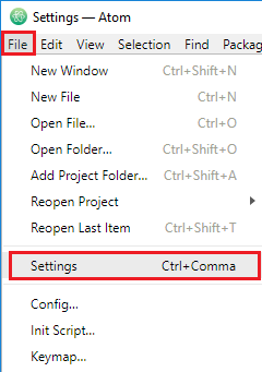 On the left menu, open the “
 Search for “
 Install the “
5.
PlatformIO IDE Overview
Now, when you open Atom text editor a new window should load with the “Welcome to PlatformIO” screen:
 Press the “
 A new window loads that allows you to create a new project for your board, follow these next steps:
Name your project (example: Blink);
Search for “
A new window loads that allows you to create a new project for your board, follow these next steps:
Name your project (example: Blink);
Search for “ After the new project is created, you’ll see the project folder on the left menu that you can use to navigate through files and folders.
 Open the
  The
The 6.
TestingPlataformIO IDE
Let’s try an example to test PlataformIO IDE.
We’ll blink an LED connected to GPIO23.
Here’s the list of parts you need to follow this example:
ESP32 development board – read ESP32 Development Boards Review and Comparison
5mm LED
330 Ohm resistor
Breadboard
Jumper wires
You can use the preceding links or go directly to MakerAdvisor.com/tools to find all the parts for your projects at the best price!
Follow the next schematic to assemble your circuit.
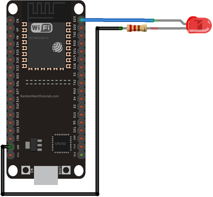 Here’s a sketch for testing purposes that blinks the LED:
#include <Arduino.h>
// ledPin refers to ESP32 GPIO 23
const int ledPin = 23;
// the setup function runs once when you press reset or power the board
void setup() {
// initialize digital pin ledPin as an output.
pinMode(ledPin, OUTPUT);
}
// the loop function runs over and over again forever
void loop() {
digitalWrite(ledPin, HIGH); // turn the LED on (HIGH is the voltage level)
delay(1000); // wait for a second
digitalWrite(ledPin, LOW); // turn the LED off by making the voltage LOW
delay(1000); // wait for a second
}
View raw code
Copy the code to the Atom text editor and follow these next steps to upload code to your ESP32 board:
Connect your ESP32 board to your computer;
Save thew newly created sketch (
Here’s a sketch for testing purposes that blinks the LED:
#include <Arduino.h>
// ledPin refers to ESP32 GPIO 23
const int ledPin = 23;
// the setup function runs once when you press reset or power the board
void setup() {
// initialize digital pin ledPin as an output.
pinMode(ledPin, OUTPUT);
}
// the loop function runs over and over again forever
void loop() {
digitalWrite(ledPin, HIGH); // turn the LED on (HIGH is the voltage level)
delay(1000); // wait for a second
digitalWrite(ledPin, LOW); // turn the LED off by making the voltage LOW
delay(1000); // wait for a second
}
View raw code
Copy the code to the Atom text editor and follow these next steps to upload code to your ESP32 board:
Connect your ESP32 board to your computer;
Save thew newly created sketch ( Wait a few seconds while the sketch uploads to your board:
 After uploading the sketch, your ESP32 should be blinking the LED attached to GPIO 23 every 1 second.
That’s it! The PlatformIO was successfully installed and you can use it to program your ESP32 board.
After uploading the sketch, your ESP32 should be blinking the LED attached to GPIO 23 every 1 second.
That’s it! The PlatformIO was successfully installed and you can use it to program your ESP32 board.
7.
PlatformIO IDE Additional Tips
We’ve just scratched the surface on what PlatformIO IDE can do.
Here’s what each button in the PlatformIO IDE does/means:
 PlatformIO Home
PlatformIO Build
PlatformIO Home
PlatformIO Build
 The PlatformIO software should automatically complete your settings.
Otherwise, select your ESP32 COM port and its baudrate.
Then, press the “
The PlatformIO software should automatically complete your settings.
Otherwise, select your ESP32 COM port and its baudrate.
Then, press the “ Just like the Arduino IDE Serial Monitor, you have a window that outputs all the Serial.println() commands used in your code:
 As you can see, it’s printing the messages: “LED on” and “LED off”.
Wrapping Up
We recommend using the following links as a resource to explore the additional functionalities and features that PlaformIO offers:
PlatformIO IDE official website
PlatformIO IDE user guide
PlatformIO IDE documentation
PlatformIO IDE Espressif 32 (ESP32) boards
We have other tutorials with ESP32 that you might like:
ESP32 Web Server – Arduino IDE
Build an All-in-One ESP32 Weather Station
Alexa (Echo) with ESP32 – Voice Controlled Relay
We hope you’ve found this tutorial useful.If you like ESP32 and you want to learn more, we recommend enrolling in 7 Different Ways to Send Notifications with the ESP32
In this guide, we’ll show you seven different ways to send notifications with the ESP32. We’ll cover sending SMS, emails, WhatsApp messages, and Telegram messages. We’ll show you different options for each notification type. In this tutorial, we’ll cover the following notification methods:
Send Emails with the ESP32
 There are different methods to send emails with the ESP32.
Send Messages to Telegram with the ESP32
Send Messages to WhatsApp with the ESP32
Send an SMS with the ESP32
To send SMS with the ESP32, you can connect it to a modem and use a SIM card or use a third-party service. There are several modules for the ESP32 that allow you to connect a SIM card. There are also ESP32 development boards that come with a built-in modem like the SIM800L or SIM7000G. To send SMS with these modules, you need a SIM card with an SMS plan or credit. We have tutorials showing how to send SMS with the ESP32 SIM800L and ESP32 SIM7000G. Check them below: ESP32 SIM800L: Send Text Messages (SMS Alert) with Sensor Readings LILYGO T-SIM7000G ESP32: Send SMSWrapping Up
In this article, we’ve shown you different ways to send notifications with the ESP32.
We’ve covered sending emails, messages to Telegram, messages to WhatsApp, and SMS.
Sending notifications with the ESP32 is a very useful feature.
For example, to send an alert when motion is detected, when a sensor is above or below a certain threshold value, or to send you messages periodically with sensor values or GPIO states.
We hope you’ve found this compilation useful.
Learn more about the ESP32 with our resources:
Learn ESP32 with Arduino IDE
Build Web Servers with ESP32 and ESP8266
Firebase Web App with ESP32 and ESP8266
Free ESP32 Projects and Tutorials
Send SMS with the ESP32 (Twilio)
This guide shows how to send SMS with the ESP32 using an online service called Twilio. With this service, you can send SMS with the ESP32 without needing a GSM module or a dedicated physical SIM card. Using Twilio is not free but you can sign up for a free trial for testing purposes. We’ll use a free trial account throughout the tutorial. You can send SMS with the ESP32 without the need to rely on third-party services if you have a GSM module and a dedicated SIM card.
We have tutorials showing how to send SMS with the ESP32 using the SIM800L and SIM7000G modules:
ESP32 SIM800L: Send Text Messages (SMS Alert) with Sensor Readings
LILYGO T-SIM7000G ESP32: Connect to the Internet, Send SMS, and Get GPS Data
If you’re looking for different types of notifications and alerts with the ESP32, you can check the following tutorials:
How to send
You can send SMS with the ESP32 without the need to rely on third-party services if you have a GSM module and a dedicated SIM card.
We have tutorials showing how to send SMS with the ESP32 using the SIM800L and SIM7000G modules:
ESP32 SIM800L: Send Text Messages (SMS Alert) with Sensor Readings
LILYGO T-SIM7000G ESP32: Connect to the Internet, Send SMS, and Get GPS Data
If you’re looking for different types of notifications and alerts with the ESP32, you can check the following tutorials:
How to send Introducing Twilio
Creating a Free Trial Account
Go to https://www.twilio.com/ and click on  Enter your details and get started with a free trial.

Set Up the Free Twilio Trial Account
There are some steps you need to follow to set up your free Twilio trial account.
We’ll describe the steps you need to follow in the present tutorial.
You can also check Twilio’s official instructions here .
Verify your personal phone number
When you sign up for your free trial account, you verified your personal phone number. It should be on the list of verified phone numbers on your dashboard:
Verify other recipient numbers
When using the free trial account, you must verify all numbers that you’ll want to send an SMS. When verifying the numbers, you’ll get an SMS with a verification code that you need to insert. So, you need to have physical access to those numbers. This is not needed on the paid account. On that previous menu (
Get a Twilio Phone Number
To send messages using Twilio, you’ll need to purchase a Twilio phone number. At the time of writing this tutorial, when I signed up for the free account, I got a $15.50 credit, which is enough to get a phone number and test sending some SMS. On your dashboard, on the left sidebar, go to

Programmable Messaging – Get Set Up
Now, you have everything set up to start creating a programmable messaging service.
On your dashboard, on the left sidebar click on  Give a name to the Messaging Service, for example, ESP32 Alerts and click on
  Then, select the Twilio phone number you created previously and click on
  After that, the programmable messaging service will be all set up.
You’ll get access to your account information: account SID and Auth token.
You’ll need them later in the ESP32 code.
After that, the programmable messaging service will be all set up.
You’ll get access to your account information: account SID and Auth token.
You’ll need them later in the ESP32 code.
 You can test if everything is working as expected by clicking on
  After a few seconds, you should receive the test SMS on the selected number.
 All SMS sent from a Twilio trial account will have the text: “Sent from your Twilio trial account”.
This text doesn’t show up on premium accounts.
All SMS sent from a Twilio trial account will have the text: “Sent from your Twilio trial account”.
This text doesn’t show up on premium accounts.
ESP32: Send SMS using Twilio
Sending SMS using Twilio is very straightforward thanks to its API.
You can read the SMS API documentation .
You simply make HTTP requests with the ESP32 with the right parameters (accordingly to Twilio’s API) to send SMS.
You can check this tutorial about HTTP requests with the ESP32 .
Or you can use a library that takes care of all that, and you just need to insert your Twilio account details and the SMS body text.
Throughout this tutorial, we’ll use a library called twilio-esp32-client .
Installing the twilio-esp32-client Library
The twilio-esp32-client library can be installed through the Arduino IDE Library Manager. Go to
ESP32 Send SMS using Twilio – Code
Sending code using Twilio using theHow the Code Works
Start by including the twilio-esp32-client library. #include "twilio.hpp" Insert your network credentials on the following lines: static const char *ssid = "REPLACE_WITH_YOUR_SSID"; static const char *password = "REPLACE_WITH_YOUR_PASSWORD"; Insert your Twilio account details: the , and the . static const char *account_sid = "REPLACE_WITH_YOUR_ACCOUNT_SSID"; static const char *auth_token = "REPLACE_WITH_YOUR_ACCOUNT_AUTH_TOKEN"; // Phone number should start with "+<countrycode>" static const char *from_number = "REPLACE_WITH_TWILIO_PHONE_NUMBER"; Insert the recipient number and the message. // Phone number should start with "+<countrycode>" static const char *to_number = "INSERT_RECIPIENT_NUMBER"; static const char *message = "Hello from my ESP32 (via twilio)"; If you’re using a free trial account, the recipient number must be on the . Create a Twilio pointer variable called twilio. Twilio *twilio; In the setup(), initialize the Serial Monitor and connect the ESP32 to your local network so that it can get access to the internet and make the HTTP requests to send SMS. Serial.begin(115200); Serial.print("Connecting to WiFi network ;"); Serial.print(ssid); Serial.println("'..."); WiFi.begin(ssid, password); while (WiFi.status() != WL_CONNECTED) { Serial.println("Connecting..."); delay(500); } Serial.println("Connected!"); The following line instantiates a new Twilio instance with the account details: twilio = new Twilio(account_sid, auth_token); Then call the send_message() function that accepts as arguments the recipient number, the sender number, the message, and a variable to hold the response. This function makes an HTTP request in the background with all the necessary parameters to Twilio API to send SMS. String response; bool success = twilio->send_message(to_number, from_number, message, response); if (success) { Serial.println("Sent message successfully!"); } else { Serial.println(response); } } This function will return true if the message is successfully sent or the response of the HTTP request in case it fails. Sending an SMS is not free and it will be deducted from the credit on your Twilio account. So, we’re just sending one SMS on the setup() when the board starts. The idea is to apply this sample code to your own project. The loop() is empty. void loop() { }Demonstration
After inserting all the required details, you can upload the code to your ESP32 board. Select an ESP32 board in
After uploading, open the Serial Monitor at a baud rate of 115200.
Press the ESP32 RST button to restart the board.
If everything goes as expected, you should receive a similar message as shown below.
 After a few seconds, you should receive an SMS from Twilio on your phone.

Wrapping Up
In this tutorial, you learned how to send SMS with the ESP32 using Twilio programmable messaging API.
The advantage of using this method is that you don’t need to have a modem or a physical SIM card to send SMS with your board.
However, you need to buy a Twilio phone number, and you’ll need to pay a monthly subscription for the card.
You’ll also need to pay for each SMS you send.
You can sign up for a free trial account that gives you credit to experiment with Twilio in your projects—so, you can try their services for a while for free.
If you feel their service is the right for your projects, then you can update your account later on.
You can also send SMS with the ESP32 using other methods—using modems like the SIM800L, SIM7000G, and others.
We have tutorials showing how to send SMS with the ESP32 using the SIM800L and SIM7000G modules:
ESP32 SIM800L: Send Text Messages (SMS Alert) with Sensor Readings
LILYGO T-SIM7000G ESP32: Connect to the Internet, Send SMS, and Get GPS Data
We hope you find this tutorial useful.
Error Downloading URLs on Windows PC
If you’re having trouble compiling code for your ESP32 or ESP8266 boards using Arduino IDE due to an error downloading the boards’ URLs, you can follow this guide to help you fix the Arduino IDE installation on a Windows PC. Installing ESP32 Board in Arduino IDE (Windows, Mac OS X, Linux) Installing ESP8266 Board in Arduino IDE (Windows, Mac OS X, Linux) If you see a similar error in your Arduino IDE or any error related to downloading URLs, cleaning your Arduino IDE installation folder usually solves this issue.
 If your Arduino IDE doesn’t launch (you click the Arduino icon and nothing happens) this trick might also solve the issue.
Fixing Arduino IDE Installation
1.
In your Windows PC, open the
2.
Go to your  3.
Select the
3.
Select the  4.
Open the
4.
Open the  5.
That’s it! Now, you just need to re-install the ESP32 and ESP8266 board add-ons.
5.
That’s it! Now, you just need to re-install the ESP32 and ESP8266 board add-ons.

Installing ESP32 and ESP8266 Board Add-on in Arduino IDE
Finally, you need to re-install the ESP board add-ons, you can either continue reading this guide or open one of the next links for more detailed instructions:
Installing ESP32 Board in Arduino IDE (Windows, Mac OS X, Linux)
Installing ESP8266 Board in Arduino IDE (Windows, Mac OS X, Linux)
1.
In your Arduino IDE, go to
2.
Enter the following URLs into the “A
3.
Open the Boards Manager.
Go to
4.
Search for
5.
Search for 
Testing the ESP32 and ESP8266 Board Add-on Installed in Arduino IDE
Plug the ESP32 or ESP8266 boardto your computer.
With your Arduino IDE open, follow these steps:
1.
Select your Board in
2.
Select the Port (if you don’t see the COM Port in your Arduino IDE, you need to install theCP210x USB to UART Bridge VCP Drivers ):
3.
Open the following example (or any other example) under
4.
A new sketch opens in your Arduino IDE:
5.
Press the
6.
If everything went as expected, you should see a “
If you get the “Timed out waiting for packet header” error, follow this guide: [SOLVED] Failed to connect to ESP32: Timed out waiting for packet header .
7.
Open the Arduino IDE Serial Monitor at a baud rate of 115200:
8.
Press the ESP on-board
Wrapping Up
We hope this guide fixed your Arduino IDE installation.
Now, you’re ready to start building your IoT projects with the ESP32 and ESP8266 boards!
For more ESP32 troubleshooting tips, try our ESP32 Troubleshooting Guide .
Some ESP32 development boards (read Best ESP32 boards ) don’t go into flashing/uploading mode automatically when uploading a new code.
This means that when you try to upload a new sketch to your ESP32, the Arduino IDE fails to connect to your board, and you get the following error message:

Holding the BOOT/FLASH button
One of the ways to solve this is holding-down the “How to fix the Error?
To make your ESP32 board go into flashing/uploading mode automatically, you can 

 Before trying to upload a new code, you should check the connections with a multimeter in continuity mode – check that you haven’t inadvertently solder anything to the next pin.
 If everything is soldered properly, you won’t need to press the BOOT button when uploading new code.
You also won’t get the Fatal Error Occurred: “Failed to connect to ESP32: Timed out waiting for packet header”.
If everything is soldered properly, you won’t need to press the BOOT button when uploading new code.
You also won’t get the Fatal Error Occurred: “Failed to connect to ESP32: Timed out waiting for packet header”.

Wrapping Up
We hope you’ve found this trick useful and it solved your problem.
Thanks to Ben Hall for the suggestion.
For more ESP32 troubleshooting tips, consult the ESP32 troubleshooting guide .
To learn more about ESP32 enroll in the SMART HOME with Raspberry Pi, ESP32, ESP8266 [eBook]
[SOLVED] Reconnect ESP32 to Wi-Fi Network After Lost Connection
This quick guide shows how you can reconnect your ESP32 to a Wi-Fi network after losing the connection. This can be useful in the following scenarios: the ESP32 temporarily loses Wi-Fi signal; the ESP32 is temporarily out of the router’s Wi-Fi range; the router restarts; the router loses internet connection or other situations. We have a similar guide for the ESP8266 NodeMCU board:
[SOLVED] Reconnect ESP8266 NodeMCU to Wi-Fi Network After Lost Connection
You may also want to take a look at WiFiMulti .
It allows you to register multiple networks (SSID/password combinations).
The ESP32 will connect to the Wi-Fi network with the strongest signal (RSSI).
If the connection is lost, it will connect to the next network on the list.
Read: ESP32 WiFiMulti: Connect to the Strongest Wi-Fi Network (from a list of networks) .
We have a similar guide for the ESP8266 NodeMCU board:
[SOLVED] Reconnect ESP8266 NodeMCU to Wi-Fi Network After Lost Connection
You may also want to take a look at WiFiMulti .
It allows you to register multiple networks (SSID/password combinations).
The ESP32 will connect to the Wi-Fi network with the strongest signal (RSSI).
If the connection is lost, it will connect to the next network on the list.
Read: ESP32 WiFiMulti: Connect to the Strongest Wi-Fi Network (from a list of networks) .
Reconnect to Wi-Fi Network After Lost Connection
To reconnect to Wi-Fi after a connection is lost, you can use WiFi.reconnect() to try to reconnect to the previously connected access point: WiFi.reconnect() Or, you can call WiFi.disconnect() followed by WiFi.begin(ssid,password). WiFi.disconnect(); WiFi.begin(ssid, password); Alternatively, you can also try to restart the ESP32 with ESP.restart() when the connection is lost. You can add something like the snippet below to the loop() that checks once in a while if the board is connected and tries to reconnect if it has lost connection. unsigned long currentMillis = millis(); // if WiFi is down, try reconnecting if ((WiFi.status() != WL_CONNECTED) && (currentMillis - previousMillis >=interval)) { Serial.print(millis()); Serial.println("Reconnecting to WiFi..."); WiFi.disconnect(); WiFi.reconnect(); previousMillis = currentMillis; } Don’t forget to declare the previousMillis and interval variables. The interval corresponds to the period of time between each check in milliseconds (for example 30 seconds): unsigned long previousMillis = 0; unsigned long interval = 30000; Here’s a complete example. /* Rui Santos Complete project details at https://RandomNerdTutorials.com/solved-reconnect-esp32-to-wifi/ Permission is hereby granted, free of charge, to any person obtaining a copy of this software and associated documentation files. The above copyright notice and this permission notice shall be included in all copies or substantial portions of the Software. */ #include <WiFi.h> // Replace with your network credentials (STATION) const char* ssid = "REPLACE_WITH_YOUR_SSID"; const char* password = "REPLACE_WITH_YOUR_PASSWORD"; unsigned long previousMillis = 0; unsigned long interval = 30000; void initWiFi() { WiFi.mode(WIFI_STA); WiFi.begin(ssid, password); Serial.print("Connecting to WiFi .."); while (WiFi.status() != WL_CONNECTED) { Serial.print('.'); delay(1000); } Serial.println(WiFi.localIP()); } void setup() { Serial.begin(115200); initWiFi(); Serial.print("RSSI: "); Serial.println(WiFi.RSSI()); } void loop() { unsigned long currentMillis = millis(); // if WiFi is down, try reconnecting every CHECK_WIFI_TIME seconds if ((WiFi.status() != WL_CONNECTED) && (currentMillis - previousMillis >=interval)) { Serial.print(millis()); Serial.println("Reconnecting to WiFi..."); WiFi.disconnect(); WiFi.reconnect(); previousMillis = currentMillis; } } View raw code This example shows how to connect to a network and checks every 30 seconds if it is still connected. If it isn’t, it disconnects and tries to reconnect again. Alternatively, you can also use Wi-Fi Events to detect that the connection was lost and call a function to handle what to do when that happens (see the next section).ESP32 Wi-Fi Events
The ESP32 is able to handle different Wi-Fi events. With Wi-Fi Events, you don’t need to be constantly checking the Wi-Fi state. When a certain event happens, it automatically calls the corresponding handling function. The following events are very useful to detect if the connection was lost or reestablished: ARDUINO_EVENT_WIFI_STA_CONNECTED: the ESP32 is connected in station mode to an access point/hotspot (your router); ARDUINO_EVENT_WIFI_STA_DISCONNECTED: the ESP32 station disconnected from the access point. Go to the next section to see an application example.Reconnect to Wi-Fi Network After Lost Connection (Wi-Fi Events)
Wi-Fi events can be useful to detect that a connection was lost and try to reconnect right after (use the ARDUINO_EVENT_WIFI_STA_DISCONNECTED event). Here’s a sample code: /* Rui Santos Complete project details at https://RandomNerdTutorials.com/solved-reconnect-esp32-to-wifi/ Permission is hereby granted, free of charge, to any person obtaining a copy of this software and associated documentation files. The above copyright notice and this permission notice shall be included in all copies or substantial portions of the Software. */ #include <WiFi.h> const char* ssid = "REPLACE_WITH_YOUR_SSID"; const char* password = "REPLACE_WITH_YOUR_PASSWORD"; void WiFiStationConnected(WiFiEvent_t event, WiFiEventInfo_t info){ Serial.println("Connected to AP successfully!"); } void WiFiGotIP(WiFiEvent_t event, WiFiEventInfo_t info){ Serial.println("WiFi connected"); Serial.println("IP address: "); Serial.println(WiFi.localIP()); } void WiFiStationDisconnected(WiFiEvent_t event, WiFiEventInfo_t info){ Serial.println("Disconnected from WiFi access point"); Serial.print("WiFi lost connection. Reason: "); Serial.println(info.wifi_sta_disconnected.reason); Serial.println("Trying to Reconnect"); WiFi.begin(ssid, password); } void setup(){ Serial.begin(115200); // delete old config WiFi.disconnect(true); delay(1000); WiFi.onEvent(WiFiStationConnected, WiFiEvent_t::ARDUINO_EVENT_WIFI_STA_CONNECTED); WiFi.onEvent(WiFiGotIP, WiFiEvent_t::ARDUINO_EVENT_WIFI_STA_GOT_IP); WiFi.onEvent(WiFiStationDisconnected, WiFiEvent_t::ARDUINO_EVENT_WIFI_STA_DISCONNECTED); /* Remove WiFi event Serial.print("WiFi Event ID: "); Serial.println(eventID); WiFi.removeEvent(eventID);*/ WiFi.begin(ssid, password); Serial.println(); Serial.println(); Serial.println("Wait for WiFi... "); } void loop(){ delay(1000); } View raw codeHow it Works?
In this example, we’ve added three Wi-Fi events: when the ESP32 connects when it gets an IP address, and when it disconnects: ARDUINO_EVENT_WIDI_STA_CONNECTED, ARDUINO_EVENT_WIFI_STA_GOT_IP, and ARDUINO_EVENT_WIFI_STA_DISCONNECTED, respectively. When the ESP32 station connects to the access point (ARDUINO_EVENT_WIFI_STA_CONNECTED event), the WiFiStationConnected() function will be called: WiFi.onEvent(WiFiStationConnected, WiFiEvent_t::ARDUINO_EVENT_WIFI_STA_CONNECTED); The WiFiStationConnected() function simply prints that the ESP32 connected to an access point (for example, your router) successfully. However, you can modify the function to do any other task (like light up an LED to indicate that it is successfully connected to the network). void WiFiStationConnected(WiFiEvent_t event, WiFiEventInfo_t info){ Serial.println("Connected to AP successfully!"); } When the ESP32 gets its IP address, the WiFiGotIP() function runs. WiFi.onEvent(WiFiGotIP, WiFiEvent_t::ARDUINO_EVENT_WIFI_STA_GOT_IP); That function simply prints the IP address on the Serial Monitor. void WiFiGotIP(WiFiEvent_t event, WiFiEventInfo_t info){ Serial.println("WiFi connected"); Serial.println("IP address: "); Serial.println(WiFi.localIP()); } When the ESP32 loses the connection with the access point (ARDUINO_EVENT_WIFI_STA_DISCONNECTED), the WiFiStationDisconnected() function is called. WiFi.onEvent(WiFiStationDisconnected, WiFiEvent_t::ARDUINO_EVENT_WIFI_STA_DISCONNECTED); That function prints a message indicating that the connection was lost and tries to reconnect: void WiFiStationDisconnected(WiFiEvent_t event, WiFiEventInfo_t info){ Serial.println("Disconnected from WiFi access point"); Serial.print("WiFi lost connection. Reason: "); Serial.println(info.disconnected.reason); Serial.println("Trying to Reconnect"); WiFi.begin(ssid, password); }Wrapping Up
This quick tutorial shows different ways of how you can reconnect your ESP32 to a Wi-Fi network after the connection is lost.
We recommend that you take a look at the following tutorial to better understand some of the most used ESP32 Wi-Fi functions:
ESP32 Useful Wi-Fi Library Functions (Arduino IDE)
One of the best applications of the ESP32 Wi-Fi capabilities is building web servers.
If you want to use the ESP32 or ESP8266 boards to build Web Server projects, you might like our eBook:
ESP32 Web Server: Control Stepper Motor (HTML Form)
In this tutorial, you’ll learn how to create a web server with the ESP32 to control a stepper motor remotely. The web server displays a web page with an HTML form that allows you to select the direction and number of steps you want the motor to move.
Table of Contents
Control Stepper Motor with WebSockets (HTML, CSS, JavaScript)
In the picture below, you can see the three web server projects we’ll build (number 3 is in this post ).
 This is a didactic tutorial where you’ll learn more about creating web pages and interaction between the ESP32 and the client.
We’ll show you how to create the web page step-by-step with HTML and send the form results to the ESP32 via HTTP POST to control the stepper motor.
Later, you’ll add some CSS to style the web page to improve its look.
Finally, we’ll show you how to use Websockets for bidirectional communication between the server and the client.
This will allow us to know on the web interface whether the motor is spinning or stopped.
This section will add some JavaScript to handle WebSocket communication and add some cool animations to the web page.
The following articles might be useful to understand the concepts covered throughout this tutorial:
ESP32 with Stepper Motor (28BYJ-48 and ULN2003 Motor Driver)
Input Data on HTML Form ESP32/ESP8266 Web Server using Arduino IDE
ESP32 WebSocket Server: Control Outputs (Arduino IDE)
This is a didactic tutorial where you’ll learn more about creating web pages and interaction between the ESP32 and the client.
We’ll show you how to create the web page step-by-step with HTML and send the form results to the ESP32 via HTTP POST to control the stepper motor.
Later, you’ll add some CSS to style the web page to improve its look.
Finally, we’ll show you how to use Websockets for bidirectional communication between the server and the client.
This will allow us to know on the web interface whether the motor is spinning or stopped.
This section will add some JavaScript to handle WebSocket communication and add some cool animations to the web page.
The following articles might be useful to understand the concepts covered throughout this tutorial:
ESP32 with Stepper Motor (28BYJ-48 and ULN2003 Motor Driver)
Input Data on HTML Form ESP32/ESP8266 Web Server using Arduino IDE
ESP32 WebSocket Server: Control Outputs (Arduino IDE)
1) Parts Required
To follow this tutorial, you need the following parts: 28BYJ-48 Stepper Motor + ULN2003 Motor Driver ESP32 (read Best ESP32 Development Boards ) Jumper Wires 5V Power Supply2) Arduino IDE and ESP32 Boards Add-on
We’ll program the ESP32 using Arduino IDE. So, you must have the ESP32 add-on installed. Follow the next tutorial if you haven’t already: Installing ESP32 Board in Arduino IDE (Windows, Mac OS X, Linux) If you want to use VS Code with the PlatformIO extension, follow the next tutorial instead to learn how to program the ESP32: Getting Started with VS Code and PlatformIO IDE for ESP32 and ESP8266 (Windows, Mac OS X, Linux Ubuntu)3) Filesystem Uploader Plugin
To upload the HTML, CSS, and JavaScript files needed to build this project to the ESP32 filesystem (SPIFFS), we’ll use a plugin for Arduino IDE:4) Libraries
To build this project, you need to install the following libraries: ESPAsyncWebServer (.zip folder) AsyncTCP (.zip folder) The ESPAsyncWebServer and AsynTCP libraries aren’t available to install through the Arduino Library Manager. You need to click on the previous links to download the library files. Then, in your Arduino IDE, go toInstalling Libraries (VS Code + PlatformIO)
If you’re programming the ESP32 using PlatformIO, you should add the following lines to the platformio.ini file to include the libraries (also change the Serial Monitor speed to 115200): monitor_speed=115200 lib_deps = ESP Async WebServer arduino-libraries/Arduino_JSON @ 0.1.0 arduino-libraries/Stepper @ ^1.1.35) Schematic Diagram
The following schematic diagram shows the connections between the stepper motor to the ESP32.
| IN1 | GPIO 19 |
| IN2 | GPIO 18 |
| IN3 | GPIO 5 |
| IN4 | GPIO 17 |
1.Control Stepper Motor with HTML Form
In this section, you’ll learn how to create a simple HTML form to control the stepper motor. Here’s how it works:
On the web page, you can select whether you want the motor to turn
Here’s how it works:
On the web page, you can select whether you want the motor to turn HTML Form and Input Fields
In this section, we’ll take a look at the HTML to build the form. In HTML, the <form> tag is used to create an HTML form to collect user input. The user input is then sent to the server (ESP32 or ESP8266) for processing. Based on the values collected on the form, your ESP board may perform different actions—in this case, spin the motor a determined number of steps. Here’s the HTML we’ll use for this project. <!DOCTYPE html> <html> <head> <title>Stepper Motor</title> <meta name="viewport" content="width=device-width, initial-scale=1"> </head> <body> <h1>Stepper Motor Control</h2> <form action="/" method="POST"> <input type="radio" name="direction" value="CW" checked> <label for="CW">Clockwise</label> <input type="radio" name="direction" value="CCW"> <label for="CW">Counterclockwise</label><br><br><br> <label for="steps">Number of steps:</label> <input type="number" name="steps"> <input type="submit" value="GO!"> </form> </body> </html> An HTML form contains different form elements. All form elements are enclosed inside the <form> tag. It contains controls <input> (radio buttons and number input field) and labels for those controls (<label>). Additionally, the <form> tag must include the action attribute that specifies what you want to do when the form is submitted. In our case, we want to send that data to the server (ESP32/ESP8266) when the user clicks theRadio Buttons
 A radio button is defined as follows:
<input type="radio">
For our project, we need two radio buttons, and only one can be selected at a time.
So, we can create a group of radio buttons.
To do that, the radio buttons must share the same name (the value of the name attribute—in this case direction).
<input type="radio" name="direction">
Finally, we also need the value attribute that specifies a unique value for each radio button.
This value is not visible to the user, but it is sent to the server when you click on the submit button to identify which button was selected.
In our example, we created one radio button with the value CW (to select clockwise) and another CCW (to select counterclockwise).
<input type="radio" name="direction" value="CW">
<input type="radio" name="direction" value="CCW">
Finally, if you want one radio button to be selected by default, you can add the keyword checked.
In our example, the clockwise direction is selected by default.
<input type="radio" name="direction" value="CW" checked>
So, this is how the radio buttons and corresponding labels look like:
<input type="radio" name="direction" value="CW" checked>
<label for="CW">Clockwise</label>
<input type="radio" name="direction" value="CCW">
<label for="CW">Counterclockwise</label><br><br><br>
A radio button is defined as follows:
<input type="radio">
For our project, we need two radio buttons, and only one can be selected at a time.
So, we can create a group of radio buttons.
To do that, the radio buttons must share the same name (the value of the name attribute—in this case direction).
<input type="radio" name="direction">
Finally, we also need the value attribute that specifies a unique value for each radio button.
This value is not visible to the user, but it is sent to the server when you click on the submit button to identify which button was selected.
In our example, we created one radio button with the value CW (to select clockwise) and another CCW (to select counterclockwise).
<input type="radio" name="direction" value="CW">
<input type="radio" name="direction" value="CCW">
Finally, if you want one radio button to be selected by default, you can add the keyword checked.
In our example, the clockwise direction is selected by default.
<input type="radio" name="direction" value="CW" checked>
So, this is how the radio buttons and corresponding labels look like:
<input type="radio" name="direction" value="CW" checked>
<label for="CW">Clockwise</label>
<input type="radio" name="direction" value="CCW">
<label for="CW">Counterclockwise</label><br><br><br>
Input Field
 Finally, we also need an input field where the user enters the number of steps—an input field of type number.
The name attribute allows us to determine in which input field the user entered the data.
<input type="number" name="steps">
Finally, we also need an input field where the user enters the number of steps—an input field of type number.
The name attribute allows us to determine in which input field the user entered the data.
<input type="number" name="steps">
Submit Button
To complete the form, we need a submit button. A submit button is an input of type submit. When you click this button, the form’s data is sent to the server (the ESP32 or ESP8266 boards). The value attribute specifies the text to display on the button. <input type="submit" value="GO!"> For example, if you select the clockwise direction and enter 2000 steps, the client will make the following request to the ESP: POST / Host: localhost
Code
Now that you know how to create the HTML form, let’s go through the Arduino code. The HTML text can be saved on an HTML file saved on the ESP32 filesystem (SPIFFS) or it can be saved in a variable in your Arduino sketch. Because the HTML text for this example is relatively simple and we don’t have CSS or JavaScript files, we’ll save the HTML text as a variable (index_html). Here’s the code to build the web server (insert your network credentials and the code will work straight away). /* Rui Santos Complete project details at https://RandomNerdTutorials.com/stepper-motor-esp32-web-server/ Permission is hereby granted, free of charge, to any person obtaining a copy of this software and associated documentation files. The above copyright notice and this permission notice shall be included in all copies or substantial portions of the Software. */ #include <Arduino.h> #include <WiFi.h> #include <AsyncTCP.h> #include <ESPAsyncWebServer.h> #include <Stepper.h> // Stepper Motor Settings const int stepsPerRevolution = 2048; // change this to fit the number of steps per revolution #define IN1 19 #define IN2 18 #define IN3 5 #define IN4 17 Stepper myStepper(stepsPerRevolution, IN1, IN3, IN2, IN4); // Replace with your network credentials const char* ssid = "REPLACE_WITH_YOUR_SSID"; const char* password = "REPLACE_WITH_YOUR_PASSWORD"; // Create AsyncWebServer object on port 80 AsyncWebServer server(80); // Search for parameters in HTTP POST request const char* PARAM_INPUT_1 = "direction"; const char* PARAM_INPUT_2 = "steps"; // Variables to save values from HTML form String direction; String steps; // Variable to detect whether a new request occurred bool newRequest = false; // HTML to build the web page const char index_html[] PROGMEM = R"rawliteral( <!DOCTYPE html> <html> <head> <title>Stepper Motor</title> <meta name="viewport" content="width=device-width, initial-scale=1"> </head> <body> <h1>Stepper Motor Control</h2> <form action="/" method="POST"> <input type="radio" name="direction" value="CW" checked> <label for="CW">Clockwise</label> <input type="radio" name="direction" value="CCW"> <label for="CW">Counterclockwise</label><br><br><br> <label for="steps">Number of steps:</label> <input type="number" name="steps"> <input type="submit" value="GO!"> </form> </body> </html> )rawliteral"; // Initialize WiFi void initWiFi() { WiFi.mode(WIFI_STA); WiFi.begin(ssid, password); Serial.print("Connecting to WiFi .."); while (WiFi.status() != WL_CONNECTED) { Serial.print('.'); delay(1000); } Serial.println(WiFi.localIP()); } void setup() { Serial.begin(115200); initWiFi(); myStepper.setSpeed(5); // Web Server Root URL server.on("/", HTTP_GET, [](AsyncWebServerRequest *request){ request->send(200, "text/html", index_html); }); // Handle request (form) server.on("/", HTTP_POST, [](AsyncWebServerRequest *request) { int params = request->params(); for(int i=0;i<params;i++){ AsyncWebParameter* p = request->getParam(i); if(p->isPost()){ // HTTP POST input1 value (direction) if (p->name() == PARAM_INPUT_1) { direction = p->value().c_str(); Serial.print("Direction set to: "); Serial.println(direction); } // HTTP POST input2 value (steps) if (p->name() == PARAM_INPUT_2) { steps = p->value().c_str(); Serial.print("Number of steps set to: "); Serial.println(steps); } } } request->send(200, "text/html", index_html); newRequest = true; }); server.begin(); } void loop() { // Check if there was a new request and move the stepper accordingly if (newRequest){ if (direction == "CW"){ // Spin the stepper clockwise direction myStepper.step(steps.toInt()); } else{ // Spin the stepper counterclockwise direction myStepper.step(-steps.toInt()); } newRequest = false; } } View raw codeHow the Code Works
Continue reading to learn how the code works, or skip to the .Include Libraries
First, include the required libraries. The WiFi, AsyncTCP, and ESPAsyncWebServer to create the web server and the Stepper library to control the stepper motor. #include <Arduino.h> #include <WiFi.h> #include <AsyncTCP.h> #include <ESPAsyncWebServer.h> #include <Stepper.h>Stepper Motor Pins and Steps per Revolution
Define the steps per revolution of your stepper motor—in our case, it’s 2048: const int stepsPerRevolution = 2048; // change this to fit the number of steps per revolution Define the motor input pins. In this example, we’re connecting to GPIOs 19, 18, 5, and 17, but you can use any other suitable GPIOs. #define IN1 19 #define IN2 18 #define IN3 5 #define IN4 17 Initialize an instance of the stepper library called myStepper. Pass as arguments the steps per revolution and the input pins. In the case of the 28BYJ-48 stepper motor, the order of the pins is IN1, IN3, IN2, IN4—it might be different for your motor. Stepper myStepper(stepsPerRevolution, IN1, IN3, IN2, IN4);Network Credentials
Insert your network credentials in the following lines. // Replace with your network credentials const char* ssid = "REPLACE_WITH_YOUR_SSID"; const char* password = "REPLACE_WITH_YOUR_PASSWORD"; Create an AsyncWebServer object called server on port 80. AsyncWebServer server(80);Initializing Variables
The PARAM_INPUT_1 and PARAM_INPUT_2 variables will be used to search for parameters in the HTTP POST request. Remember that it contains the direction and number of steps. // Search for parameters in HTTP POST request const char* PARAM_INPUT_1 = "direction"; const char* PARAM_INPUT_2 = "steps"; The following variables will save the direction and number of steps. String direction; String steps; The newRequest variable will be used to check whether a new request occurred. Then, in the loop(), we’ll spin the motor when a new request is received—when the newRequest variable is true. bool newRequest = false;HTML Form
The index_html variable saves the HTML text to build the web page—we’ve seen previously how the HTML to build the web page with the form works. // HTML to build the web page const char index_html[] PROGMEM = R"rawliteral( <!DOCTYPE html> <html> <head> <title>Stepper Motor</title> <meta name="viewport" content="width=device-width, initial-scale=1"> </head> <body> <h1>Stepper Motor Control</h2> <form action="/" method="POST"> <input type="radio" name="direction" value="CW" checked> <label for="CW">Clockwise</label> <input type="radio" name="direction" value="CCW"> <label for="CW">Counterclockwise</label><br><br><br> <label for="steps">Number of steps:</label> <input type="number" name="steps"> <input type="submit" value="GO!"> </form> </body> </html> )rawliteral";initWiFi()
The initWiFi() function initializes WiFi. // Initialize WiFi void initWiFi() { WiFi.mode(WIFI_STA); WiFi.begin(ssid, password); Serial.print("Connecting to WiFi .."); while (WiFi.status() != WL_CONNECTED) { Serial.print('.'); delay(1000); } Serial.println(WiFi.localIP()); } In this example, the ESP is set as a Wi-Fi station (it connects to your router). If you don’t have a router nearby, you can set your board as an Access Point. You can read the next tutorial to learn how to set the board as an access point: How to Set an ESP32 Access Point (AP) for Web Serversetup()
In the setup(), initialize the Serial Monitor. Serial.begin(115200); Call the initWiFi() function to initialize WiFi. initWiFi(); And set the stepper motor speed in rpm. myStepper.setSpeed(5);Handle requests
Then, handle the web server. When you receive a request on the root (/) URL—this happens when you access the ESP IP address—send the HTML text to build the web page: server.on("/", HTTP_GET, [](AsyncWebServerRequest *request){ request->send(200, "text/html", index_html); }); Then, you need to handle what happens when the ESP receives a POST request with the form details. server.on("/", HTTP_POST, [](AsyncWebServerRequest *request) { First, we search for parameters in the HTTP POST request: int params = request->params(); for(int i=0;i<params;i++){ AsyncWebParameter* p = request->getParam(i); if(p->isPost()){ If one of the parameters is equal to PARAM_INPUT_1, we know its value contains the direction of the motor. If that’s the case, we get the value of that parameter and save it in the direction variable. if (p->name() == PARAM_INPUT_1) { direction = p->value().c_str(); Serial.print("Direction set to: "); Serial.println(direction); } We follow a similar procedure for PARAM_INPUT_2, but we save the value in the steps variable. if (p->name() == PARAM_INPUT_2) { steps = p->value().c_str(); Serial.print("Number of steps set to: "); Serial.println(steps); } Finally, we respond with the content of the HTML page—it will reload the page. request->send(200, "text/html", index_html); After this, we set the newRequest variable to true, so that it spins the motor in the loop(). newRequest = true;loop()
Let’s take a look at the loop() section. If the newRequest variable is true, we’ll check what’s the spinning direction: CW or CCW. If it is CW, we move the motor the number of steps saved in the steps variable using the step() method on the myStepper object. To move the motor counterclockwise, we just need to pass the number of steps but with a minus – sign. if (direction == "CW"){ // Spin the stepper clockwise direction myStepper.step(steps.toInt()); } else{ // Spin the stepper counterclockwise direction myStepper.step(-steps.toInt()); } After spinning the motor, set the newRequest variable to false, so that it can detect new requests again. newRequest = false;Demonstration
After inserting your network credentials, you can upload the code to your board. After uploading, open the Serial Monitor at a baud rate of 115200 and press the on-board RESET button. The ESP IP address will be displayed. Open a browser on your local network and insert the ESP IP address. You’ll get access to the HTML form to control the stepper motor. Select the direction and enter a determined number of steps.
Then, press GO!.
The stepper motor will start spinning.
At the same time, you can see the values of the direction and steps variables on the Serial Monitor.
Select the direction and enter a determined number of steps.
Then, press GO!.
The stepper motor will start spinning.
At the same time, you can see the values of the direction and steps variables on the Serial Monitor.

2.Styling the Form with CSS
In the previous section, we’ve created a plain form without any formatting. By adding some CSS to your project, your HTML page will look much better. When your HTML also includes CSS, it is easier to work if you have separated HTML and CSS files (apart from the Arduino sketch file).
So, instead of writing HTML and CSS in the Arduino sketch, we’ll create separated HTML and CSS files.
These files will then be uploaded to the ESP32 filesystem (SPIFFS) using the
When your HTML also includes CSS, it is easier to work if you have separated HTML and CSS files (apart from the Arduino sketch file).
So, instead of writing HTML and CSS in the Arduino sketch, we’ll create separated HTML and CSS files.
These files will then be uploaded to the ESP32 filesystem (SPIFFS) using the Organizing Your Files
The files you want to upload to the ESP filesystem should be placed in a folder called You should save the HTML, CSS, and JavaScript files inside a folder called
Page Overview
To better understand how styling the web page works, let’s take a closer look at the web page we’ll build.
HTML File
We need to make some modifications to the HTML file to make it easier to format using CSS. Create a file called index.html and copy the following into that file. <!DOCTYPE html> <html> <head> <title>Stepper Motor</title> <meta name="viewport" content="width=device-width, initial-scale=1"> <link rel="stylesheet" type="text/css" href="style.css"> <link rel="stylesheet" href="https://use.fontawesome.com/releases/v5.7.2/css/all.css" integrity="sha384-fnmOCqbTlWIlj8LyTjo7mOUStjsKC4pOpQbqyi7RrhN7udi9RwhKkMHpvLbHG9Sr" crossorigin="anonymous"> </head> <body> <div> <h1>Stepper Motor Control <i></i></h2> </div> <div> <form action="/" method="POST"> <input type="radio" name="direction" value="CW" checked> <label for="CW">Clockwise</label> <input type="radio" name="direction" value="CCW"> <label for="CW">Counterclockwise</label><br><br><br> <label for="steps">Number of steps:</label> <input type="number" name="steps"> <input type="submit" value="GO!"> </form> </div> </body> </html> View raw code To use a CSS file to style the HTML page, you need to reference the style sheet in your HTML document. So you need to add the following between the <head> tags of your document: <link rel="stylesheet" type="text/css" href="stylesheet.css"> This <link> tag tells the HTML file that you’re using an external style sheet to format how the page looks. The rel attribute specifies the nature of the external file. In this case, it is a style sheet—the CSS file—that will be used to alter the page’s appearance. The type attribute is set to “text/css” to indicate that you’re using a CSS file for the styles. The href attribute indicates the file location; since the file is in the same folder as the HTML file, you just need to reference the filename. Otherwise, you need to reference its file path. Now you have your style sheet connected to your HTML document. To use the fontawesome icons in the web page like the cogs, we need to add the following line. <link rel="stylesheet" href="https://cdnjs.cloudflare.com/ajax/libs/font-awesome/6.5.1/css/all.min.css"> We created a <div> tag with the class topnav to make it easier to format the first heading. <div> <h1>Stepper Motor Control <i></i></h2> </div> Then, we include the form inside a <div> tag with the class content. This will make it easier to format the area occupied by the form. <div>CSS File
Create a file called style.css with the following content to format the form. html { font-family: Arial, Helvetica, sans-serif; } h2{ font-size: 1.8rem; color: white; } .topnav { overflow: hidden; background-color: #0A1128; text-align: center; } body { margin: 0; } .content { padding: 20px; max-width: max-content; margin: 0 auto; } form{ border-radius: 5px; background-color: #f2f2f2; padding: 20px; } input[type=number], select { width: 100%; padding: 12px 20px; margin: 8px 0; display: inline-block; border: 1px solid #ccc; border-radius: 4px; box-sizing: border-box; } input[type=submit] { -webkit-appearance: none; -moz-appearance: none; appearance: none; background-color: #034078; border: none; padding: 14px 20px; text-align: center; font-size: 20px; border-radius: 4px; transition-duration: 0.4s; width: 100%; color: white; cursor: pointer; } input[type=submit]:hover { background-color: #1282A2; } input[type="radio"] { -webkit-appearance: none; -moz-appearance: none; appearance: none; border-radius: 50%; width: 16px; height: 16px; border: 2px solid #999; transition: 0.2s all linear; margin-right: 5px; position: relative; top: 4px; } input[type="radio"]:checked{ border: 6px solid #1282A2; } View raw code The html selector includes the styles that apply to the whole HTML page. In this case, we’re setting the font. html { font-family: Arial, Helvetica, sans-serif; } The h2selector includes the styles for heading 1. In our case, the heading 1 includes the text “Stepper Motor Control”. This sets the text font size and color. h2{ font-size: 1.8rem; color: white; } To select the <div> with the topnav class, use a dot (.) before the class name, like this: .topnav { Set the .topnav background color using the background-color property. You can choose any background color. We’re using #0A1128. The text is aligned at the center. Additionally, set the overflow property to hidden like this: .topnav { overflow: hidden; background-color: #0A1128; text-align: center; } It’s a bit difficult to explain what the overflow property does. The best way to understand it is to render your web page with and without that property to spot the differences. The margin of the <body>—the container that includes the whole HTML page—is set to 0 so that it occupies all the browser window space. body { margin: 0; } The following lines style the content div (that contains the form): padding and margin. Additionally, set its max-width to the maximum width of its content (the form itself). .content { padding: 20px; max-width: max-content; margin: 0 auto; } The form is a container with round borders (border-radius property) and light gray background color (background-color property). We also add some padding. form{ border-radius: 5px; background-color: #f2f2f2; padding: 20px; } Then, we need to style each individual element of the form. To select the input number, we use the input[type=number] selector. input[type=number], select { width: 100%; padding: 12px 20px; margin: 8px 0; display: inline-block; border: 1px solid #ccc; border-radius: 4px; box-sizing: border-box; }Arduino Sketch
In this project, the HTML and CSS files are saved in the ESP32 filesystem (SPIFFS). So, we need to make some modifications to the sketch. /* Rui Santos Complete project details at https://RandomNerdTutorials.com/stepper-motor-esp32-web-server/ Permission is hereby granted, free of charge, to any person obtaining a copy of this software and associated documentation files. The above copyright notice and this permission notice shall be included in all copies or substantial portions of the Software. */ #include <Arduino.h> #include <WiFi.h> #include <AsyncTCP.h> #include <ESPAsyncWebServer.h> #include "SPIFFS.h" #include <Arduino_JSON.h> #include <Stepper.h> const int stepsPerRevolution = 2048; // change this to fit the number of steps per revolution #define IN1 19 #define IN2 18 #define IN3 5 #define IN4 17 Stepper myStepper(stepsPerRevolution, IN1, IN3, IN2, IN4); // Replace with your network credentials const char* ssid = "REPLACE_WITH_YOUR_SSID"; const char* password = "REPLACE_WITH_YOUR_PASSWORD"; // Create AsyncWebServer object on port 80 AsyncWebServer server(80); // Search for parameter in HTTP POST request const char* PARAM_INPUT_1 = "direction"; const char* PARAM_INPUT_2 = "steps"; //Variables to save values from HTML form String direction; String steps; bool newRequest = false; // Initialize SPIFFS void initSPIFFS() { if (!SPIFFS.begin(true)) { Serial.println("An error has occurred while mounting SPIFFS"); } else { Serial.println("SPIFFS mounted successfully"); } } // Initialize WiFi void initWiFi() { WiFi.mode(WIFI_STA); WiFi.begin(ssid, password); Serial.print("Connecting to WiFi .."); while (WiFi.status() != WL_CONNECTED) { Serial.print('.'); delay(1000); } Serial.println(WiFi.localIP()); } void setup() { // Serial port for debugging purposes Serial.begin(115200); initWiFi(); initSPIFFS(); myStepper.setSpeed(5); // Web Server Root URL server.on("/", HTTP_GET, [](AsyncWebServerRequest *request){ request->send(SPIFFS, "/index.html", "text/html"); }); server.serveStatic("/", SPIFFS, "/"); server.on("/", HTTP_POST, [](AsyncWebServerRequest *request) { int params = request->params(); for(int i=0;i<params;i++){ AsyncWebParameter* p = request->getParam(i); if(p->isPost()){ // HTTP POST input1 value if (p->name() == PARAM_INPUT_1) { direction = p->value().c_str(); Serial.print("Direction set to: "); Serial.println(direction); } // HTTP POST input2 value if (p->name() == PARAM_INPUT_2) { steps = p->value().c_str(); Serial.print("Number of steps set to: "); Serial.println(steps); // Write file to save value } newRequest = true; //Serial.printf("POST[%s]: %s\n", p->name().c_str(), p->value().c_str()); } } request->send(SPIFFS, "/index.html", "text/html"); }); server.begin(); } void loop() { if (newRequest){ if (direction == "CW"){ myStepper.step(steps.toInt()); Serial.print("CW"); } else{ myStepper.step(-steps.toInt()); } newRequest = false; } } View raw code Let’s take a look at the modifications you need to make. First, you need to include the SPIFFS.h library. #include "SPIFFS.h" Then, you need to initialize SPIFFS. We created a function called initSPIFFS() to do that. void initSPIFFS() { if (!SPIFFS.begin(true)) { Serial.println("An error has occurred while mounting SPIFFS"); } else { Serial.println("SPIFFS mounted successfully"); } } Then, you need to call that function in the setup() before initializing the web server. initSPIFFS(); Then, to handle requests, you need to indicate that your HTML file is saved in SPIFFS, as follows: server.on("/", HTTP_GET, [](AsyncWebServerRequest *request){ request->send(SPIFFS, "/index.html", "text/html"); }); When the HTML file loads on your browser, it will make a request for the CSS file. This is a static file saved on the same directory (SPIFFS). So, we can simply add the following line to serve static files in a directory when requested by the root URL. It will serve the CSS file automatically. server.serveStatic("/", SPIFFS, "/");Upload Code and Files
Before uploading, you can use the following link to:
Inside that folder, you should save the HTML and CSS files.
Then, upload the code to your ESP32 board.
Make sure you have the right board and COM port selected.
Also, make sure you’ve added your network credentials.
After uploading the code, you need to upload the files.
Go to
When everything is successfully uploaded, open the Serial Monitor at a baud rate of 115200.
Press the ESP32 EN/RST button, and it should print the ESP32 IP address.
Demonstration
Open a browser on your local network and paste the ESP32 IP address. You’ll get access to the HTML form to control the stepper motor. This works similarly to the example of the previous section, but with a better look.
Wrapping Up
This tutorial is already quite long.
So, we’ll include the third part of this tutorial in a separate publication.
In that third part, the ESP32 and the client communicate using WebSocket protocol and the web page shows whether the motor is spinning or stopped.
We’ve also included an animation with some gears spinning in the same direction as the motor.
Continue to ESP32 Web Server: Control Stepper Motor (WebSocket)
In this guide you’ll learn how to create a web server with the ESP32 that displays a web page to control a stepper motor. The web page allows you to insert the number of steps and select clockwise or counterclockwise direction. Additionally, it also shows whether the motor is currently spinning or if it is stopped. The communication between the client and the server is achieved via WebSocket protocol. All clients are updated with the current motor state. This tutorial is the second part of this article
 1) Parts Required
To follow this tutorial, you need the following parts: 28BYJ-48 Stepper Motor + ULN2003 Motor Driver ESP32 (read Best ESP32 Development Boards ) Jumper Wires 5V Power Supply2) Arduino IDE and ESP32 Boards Add-on
We’ll program the ESP32 using Arduino IDE. So, you must have the ESP32 add-on installed. Follow the next tutorial if you haven’t already: Installing ESP32 Board in Arduino IDE (Windows, Mac OS X, Linux) If you want to use VS Code with the PlatformIO extension, follow the next tutorial instead to learn how to program the ESP32: Getting Started with VS Code and PlatformIO IDE for ESP32 and ESP8266 (Windows, Mac OS X, Linux Ubuntu)3) Filesystem Uploader Plugin
To upload the HTML, CSS, and JavaScript files needed to build this project to the ESP32 filesystem (SPIFFS), we’ll use a plugin for Arduino IDE:4) Libraries
To build this project, you need to install the following libraries: ESPAsyncWebServer (.zip folder) AsyncTCP (.zip folder) The ESPAsyncWebServer and AsynTCP libraries aren’t available to install through the Arduino Library Manager. You need to click on the previous links to download the library files. Then, in your Arduino IDE, go toInstalling Libraries (VS Code + PlatformIO)
If you’re programming the ESP32 using PlatformIO, you should add the following lines to the platformio.ini file to include the libraries (also change the Serial Monitor speed to 115200): monitor_speed=115200 lib_deps = ESP Async WebServer arduino-libraries/Stepper @ ^1.1.35) Schematic Diagram
The following schematic diagram shows the connections between the stepper motor and the ESP32.
| IN1 | GPIO 19 |
| IN2 | GPIO 18 |
| IN3 | GPIO 5 |
| IN4 | GPIO 17 |
Project Overview
The following video shows a quick demonstration of what you’ll achieve by the end of this tutorial. The following image shows the web page you’ll build for this project. The web page shows a form where you can enter the number of steps you want the motor to move and select the direction: clockwise or counterclockwise.
It also shows the motor state: motor spinning or motor stopped.
Additionally, there’s a gear icon that spins as long as the motor is spinning.
The gear spins clockwise or counterclockwise accordingly to the chosen direction.
The web page shows a form where you can enter the number of steps you want the motor to move and select the direction: clockwise or counterclockwise.
It also shows the motor state: motor spinning or motor stopped.
Additionally, there’s a gear icon that spins as long as the motor is spinning.
The gear spins clockwise or counterclockwise accordingly to the chosen direction.
 The server and the client communicate using WebSocket protocol.
When you click on the
The server and the client communicate using WebSocket protocol.
When you click on the Organizing your Files
The files you want to upload to the ESP filesystem should be placed in a folder called data under the project folder. We’ll move three files to that folder: index.html to build the web page; style.css to style the web page; script.js to handle websocket communication and start/stop the gear animation.
You should save the HTML, CSS, and JavaScript files inside a folder called data inside the Arduino sketch folder, as shown in the previous diagram.
We’ll upload those files to the ESP32 filesystem (SPIFFS).
HTML File
Create a file called index.html with the following content: <!DOCTYPE html> <html> <head> <title>Stepper Motor</title> <meta name="viewport" content="width=device-width, initial-scale=1"> <link rel="stylesheet" type="text/css" href="style.css"> <link rel="stylesheet" href="https://use.fontawesome.com/releases/v5.7.2/css/all.css" integrity="sha384-fnmOCqbTlWIlj8LyTjo7mOUStjsKC4pOpQbqyi7RrhN7udi9RwhKkMHpvLbHG9Sr" crossorigin="anonymous"> </head> <body> <div> <h1>Stepper Motor Control <i></i></h2> </div> <div> <form> <input type="radio" name="direction" value="CW" checked> <label for="CW">Clockwise</label> <input type="radio" name="direction" value="CCW"> <label for="CW">Counterclockwise</label><br><br><br> <label for="steps">Number of steps:</label> <input type="number" name="steps"> </form> <button onclick="submitForm()">GO!</button> <p>Motor state: <span>Stopped</span></p> <p><i></i> </p> </div> </body> <script src="script.js"></script> </html> View raw code This HTML file is very similar to the one used in theCSS File
Create a file called style.css with the following content: html { font-family: Arial, Helvetica, sans-serif; } h2{ font-size: 1.8rem; color: white; } p{ font-size: 20px; text-align: center; } .topnav { overflow: hidden; background-color: #0A1128; text-align: center; } body { margin: 0; } .content { padding: 20px; max-width: max-content; margin: 0 auto; } input[type=number], select { width: 100%; padding: 12px 20px; margin: 8px 0; display: inline-block; border: 1px solid #ccc; border-radius: 4px; box-sizing: border-box; } form{ border-radius: 5px; background-color: #f2f2f2; padding: 20px; } button { background-color: #034078; border: none; padding: 14px 20px; text-align: center; font-size: 20px; border-radius: 4px; transition-duration: 0.4s; width: 100%; color: white; cursor: pointer; } button:hover { background-color: #1282A2; } input[type="radio"] { -webkit-appearance: none; -moz-appearance: none; appearance: none; border-radius: 50%; width: 16px; height: 16px; border: 2px solid #999; transition: 0.2s all linear; margin-right: 5px; position: relative; top: 4px; } input[type="radio"]:checked{ border: 6px solid #1282A2; } #motor-state{ font-weight: bold; color: red; } #gear{ font-size:100px; color:#2d3031cb; } .spin { -webkit-animation:spin 4s linear infinite; -moz-animation:spin 4s linear infinite; animation:spin 4s linear infinite; } .spin-back { -webkit-animation:spin-back 4s linear infinite; -moz-animation:spin-back 4s linear infinite; animation:spin-back 4s linear infinite; } @-moz-keyframes spin { 100% { -moz-transform: rotate(360deg); } } @-webkit-keyframes spin { 100% { -webkit-transform: rotate(360deg); } } @keyframes spin { 100% { -webkit-transform: rotate(360deg); transform:rotate(360deg); } } @-moz-keyframes spin-back { 100% { -moz-transform: rotate(-360deg); } } @-webkit-keyframes spin-back { 100% { -webkit-transform: rotate(-360deg); } } @keyframes spin-back { 100% { -webkit-transform: rotate(-360deg); transform:rotate(-360deg); } } View raw code We already covered how the CSS for the HTML form works. You can click here for a detailed explanation. Let’s take a look at the relevant parts for this tutorial. We format the motor state text font-weight (bold) and color (red). To refer to a specific id in CSS, use # followed by the id (#motor-state). #motor-state{ font-weight: bold; color: red; } The following line formats the gear icon color and size—remember that its id is gear, so we refer to it with #gear: #gear{ font-size:100px; color:#2d3031cb; } Then, we format two classes spin and spin-back that are not attributed to any HTML element yet. We’ll attribute the spin and spin-back classes to the gear using JavaScript when the motor starts moving. These classes use the animation property to rotate the gear. To learn more about how the animation property works, we recommend taking a look at this quick tutorial . .spin { -webkit-animation:spin 4s linear infinite; -moz-animation:spin 4s linear infinite; animation:spin 4s linear infinite; } .spin-back { -webkit-animation:spin-back 4s linear infinite; -moz-animation:spin-back 4s linear infinite; animation:spin-back 4s linear infinite; } @-moz-keyframes spin { 100% { -moz-transform: rotate(360deg); } } @-webkit-keyframes spin { 100% { -webkit-transform: rotate(360deg); } } @keyframes spin { 100% { -webkit-transform: rotate(360deg); transform:rotate(360deg); } } @-moz-keyframes spin-back { 100% { -moz-transform: rotate(-360deg); } } @-webkit-keyframes spin-back { 100% { -webkit-transform: rotate(-360deg); } } @keyframes spin-back { 100% { -webkit-transform: rotate(-360deg); transform:rotate(-360deg); } }JavaScript File
Create a file called script.js with the following content: var gateway = `ws://${window.location.hostname}/ws`; var websocket; window.addEventListener('load', onload); var direction; function onload(event) { initWebSocket(); } function initWebSocket() { console.log('Trying to open a WebSocket connection…'); websocket = new WebSocket(gateway); websocket.onopen = onOpen; websocket.onclose = onClose; websocket.onmessage = onMessage; } function onOpen(event) { console.log('Connection opened'); } function onClose(event) { console.log('Connection closed'); setTimeout(initWebSocket, 2000); } function submitForm(){ const rbs = document.querySelectorAll('input[name="direction"]'); direction; for (const rb of rbs) { if (rb.checked) { direction = rb.value; break; } } document.getElementById("motor-state").innerHTML = "motor spinning..."; document.getElementById("motor-state").style.color = "blue"; if (direction=="CW"){ document.getElementById("gear").classList.add("spin"); } else{ document.getElementById("gear").classList.add("spin-back"); } var steps = document.getElementById("steps").value; websocket.send(steps+"&"+direction); } function onMessage(event) { console.log(event.data); direction = event.data; if (direction=="stop"){ document.getElementById("motor-state").innerHTML = "motor stopped" document.getElementById("motor-state").style.color = "red"; document.getElementById("gear").classList.remove("spin", "spin-back"); } else if(direction=="CW" || direction=="CCW"){ document.getElementById("motor-state").innerHTML = "motor spinning..."; document.getElementById("motor-state").style.color = "blue"; if (direction=="CW"){ document.getElementById("gear").classList.add("spin"); } else{ document.getElementById("gear").classList.add("spin-back"); } } } View raw code Let’s see how the JavaScript for this project works. The gateway is the entry point to the WebSocket interface. window.location.hostname gets the current page address (the web server IP address) var gateway = `ws://${window.location.hostname}/ws`; Create a new global variable called websocket. var websocket; Create another global variable called direction that will hold the motor’s current direction: clockwise, counterclowise or stopped. var direction; Add an event listener that will call the onload function when the web page loads. window.addEventListener('load', onload); The onload() function calls the initWebSocket() function to initialize a WebSocket connection with the server. function onload(event) { initWebSocket(); } The initWebSocket() function initializes a WebSocket connection on the gateway defined earlier. We also assign several callback functions that will be triggered when the WebSocket connection is opened, closed or when a message is received. function initWebSocket() { console.log('Trying to open a WebSocket connection…'); websocket = new WebSocket(gateway); websocket.onopen = onOpen; websocket.onclose = onClose; websocket.onmessage = onMessage; } When the connection is opened, print a message in the console for debugging purposes. function onOpen(event) { console.log('Connection opened'); } If for some reason the web socket connection is closed, call the initWebSocket() function again after 2000 milliseconds (2 seconds). function onClose(event) { console.log('Connection closed'); setTimeout(initWebSocket, 2000); } Finally, we need to handle what happens when the form is submitted and when the client receives a new message (onMessage event). When the form is submitted, the submitForm() function is called: function submitForm(){ We start by getting which radio button is selected. We save the value of the selected radio button in the direction variable. const rbs = document.querySelectorAll('input[name="direction"]'); var direction; for (const rb of rbs) { if (rb.checked) { direction = rb.value; break; } } Then, we change the motor state text to motor spinning… and its color to blue. We refer to that HTML element by its id motor-state. document.getElementById("motor-state").innerHTML = "motor spinning..."; document.getElementById("motor-state").style.color = "blue"; Then, we check whether we’ve selected clockwise or counterclockwise direction to spin the gear in the right direction. To do that, we add the class spin or spin-back to the element with the gear id. if (direction=="CW"){ document.getElementById("gear").classList.add("spin"); } else{ document.getElementById("gear").classList.add("spin-back"); } We get the number of steps inserted and save it in the steps variable. var steps = document.getElementById("steps").value; Then, we finally send a message via WebSocket protocol to the server (ESP32) with the number of steps and direction separated by a &. websocket.send(steps+"&"+direction); The server (your ESP board) will send a message when it is time to change the motor state. When that happens, we save the message in the direction variable. We check the content of the message and change the motor state and gear animation accordingly. function onMessage(event) { console.log(event.data); direction = event.data; if (direction=="stop"){ document.getElementById("motor-state").innerHTML = "motor stopped" document.getElementById("motor-state").style.color = "red"; document.getElementById("gear").classList.remove("spin", "spin-back"); } else if(direction=="CW" || direction=="CCW"){ document.getElementById("motor-state").innerHTML = "motor spinning..."; document.getElementById("motor-state").style.color = "blue"; if (direction=="CW"){ document.getElementById("gear").classList.add("spin"); } else{ document.getElementById("gear").classList.add("spin-back"); } } }Arduino Sketch
Before uploading, you can use the following link to:Include Libraries
First, include the required libraries. The WiFi, AsyncTCP, and ESPAsyncWebServer to create the web server, the SPIFFS library to use the ESP32 filesystem, and the Stepper library to control the stepper motor. #include <Arduino.h> #include <WiFi.h> #include <AsyncTCP.h> #include <ESPAsyncWebServer.h> #include "SPIFFS.h" #include <Stepper.h>Stepper Motor Pins and Steps per Revolution
Define the steps per revolution of your stepper motor—in our case, it’s 2048: const int stepsPerRevolution = 2048; // change this to fit the number of steps per revolution Define the motor input pins. In this example, we’re connecting to GPIOs 19, 18, 5, and 17, but you can use any other suitable GPIOs. #define IN1 19 #define IN2 18 #define IN3 5 #define IN4 17 Initialize an instance of the stepper library called myStepper. Pass as arguments the steps per revolution and the input pins. In the case of the 28BYJ-48 stepper motor, the order of the pins is IN1, IN3, IN2, IN4—it might be different for your motor. Stepper myStepper(stepsPerRevolution, IN1, IN3, IN2, IN4);Network Credentials
Insert your network credentials in the following lines. // Replace with your network credentials const char* ssid = "REPLACE_WITH_YOUR_SSID"; const char* password = "REPLACE_WITH_YOUR_PASSWORD";AsyncWebServer and AsyncWebSocket
Create an AsyncWebServer object called server on port 80. AsyncWebServer server(80); The ESPAsyncWebServer library includes a WebSocket plugin that makes it easy to handle WebSocket connections. Create an AsyncWebSocket object called ws to handle the connections on the /ws path. AsyncWebSocket ws("/ws");Initializing Variables
The following variables will save the direction and number of steps received via WebSocket protocol. When the program first starts, the motor is stopped. String direction ="stop"; String steps; The newRequest variable will be used to check whether a new request occurred. Then, in the loop(), we’ll spin the motor when a new request is received—when the newRequest variable is true. bool newRequest = false;initSPIFFS()
The initSPIFFS() function initializes the ESP32 Filesystem. void initSPIFFS() { if (!SPIFFS.begin(true)) { Serial.println("An error has occurred while mounting SPIFFS"); } else{ Serial.println("SPIFFS mounted successfully"); } }initWiFi()
The initWiFi() function initializes WiFi. // Initialize WiFi void initWiFi() { WiFi.mode(WIFI_STA); WiFi.begin(ssid, password); Serial.print("Connecting to WiFi .."); while (WiFi.status() != WL_CONNECTED) { Serial.print('.'); delay(1000); } Serial.println(WiFi.localIP()); }Handling WebSockets – Server
Previously, you’ve seen how to handle the WebSocket connection on the client side (browser). Now, let’s take a look on how to handle it on the server side.Notify All Clients
The notifyClients() function notifies all clients with a message containing whatever you pass as a argument. In this case, we’ll want to notify all clients of the current motor state whenever there’s a change. void notifyClients(String state) { ws.textAll(state); } The AsyncWebSocket class provides a textAll() method for sending the same message to all clients that are connected to the server at the same time.Handle WebSocket Messages
The handleWebSocketMessage() function is a callback function that will run whenever we receive new data from the clients via WebSocket protocol. void handleWebSocketMessage(void *arg, uint8_t *data, size_t len) { AwsFrameInfo *info = (AwsFrameInfo*)arg; if (info->final && info->index == 0 && info->len == len && info->opcode == WS_TEXT) { data[len] = 0; message = (char*)data; steps = message.substring(0, message.indexOf("&")); direction = message.substring(message.indexOf("&")+1, message.length()); Serial.print("steps"); Serial.println(steps); Serial.print("direction"); Serial.println(direction); notifyClients(direction); newRequest = true; } } We split the message to get the number of steps and direction. message = (char*)data; steps = message.substring(0, message.indexOf("&")); direction = message.substring(message.indexOf("&")+1, message.length()); Then, we notify all clients of the motor direction so that all clients change the motor state on the web interface. notifyClients(direction); Finally, set the newRequest variable to true, so that the motors starts spinning in the loop(). newRequest = true;Configure the WebSocket server
Now we need to configure an event listener to handle the different asynchronous steps of the WebSocket protocol. This event handler can be implemented by defining the onEvent() as follows: void onEvent(AsyncWebSocket *server, AsyncWebSocketClient *client, AwsEventType type, void *arg, uint8_t *data, size_t len) { switch (type) { case WS_EVT_CONNECT: Serial.printf("WebSocket client #%u connected from %s\n", client->id(), client->remoteIP().toString().c_str()); //Notify client of motor current state when it first connects notifyClients(direction); break; case WS_EVT_DISCONNECT: Serial.printf("WebSocket client #%u disconnected\n", client->id()); break; case WS_EVT_DATA: handleWebSocketMessage(arg, data, len); break; case WS_EVT_PONG: case WS_EVT_ERROR: break; } } The type argument represents the event that occurs. It can take the following values: WS_EVT_CONNECT when a client has logged in; WS_EVT_DISCONNECT when a client has logged out; WS_EVT_DATA when a data packet is received from the client; WS_EVT_PONG in response to a ping request; WS_EVT_ERROR when an error is received from the client. There’s a section to notify any client of the current motor state when it first connects: case WS_EVT_CONNECT: Serial.printf("WebSocket client #%u connected from %s\n", client->id(), client->remoteIP().toString().c_str()); //Notify client of motor current state when it first connects notifyClients(direction); break;Initialize WebSocket
Finally, the initWebSocket() function initializes the WebSocket protocol. void initWebSocket() { ws.onEvent(onEvent); server.addHandler(&ws); }setup()
In the setup(), initialize the Serial Monitor. Serial.begin(115200); Call the initWiFi() function to initialize WiFi. initWiFi(); Call the initSPIFFS() function to initialize the filesystem. initWebSocket(); And set the stepper motor speed in rpm. myStepper.setSpeed(5);Handle requests
Then, handle the web server. When you receive a request on the root (/) URL—this is when you access the ESP IP address— send the HTML text to build the web page: server.on("/", HTTP_GET, [](AsyncWebServerRequest *request){ request->send(200, "text/html", index_html); }); When the HTML file loads on your browser, it will make a request for the CSS and JavaScript files. These are static files saved on the same directory (SPIFFS). So, we can simply add the following line to serve files in a directory when requested by the root URL. It will serve the CSS and JavaScript files automatically. server.serveStatic("/", SPIFFS, "/"); Finally, start the server. server.begin();loop()
Let’s take a look at the loop() section. If the newRequest variable is true, we’ll check what’s the spinning direction: CW or CCW. If it is CW, we move the motor the number of steps saved in the steps variable using the step() method on the myStepper object. To move the motor counterclockwise, we just need to pass the number of steps but with a minus (–) sign. if (direction == "CW"){ // Spin the stepper clockwise direction myStepper.step(steps.toInt()); } else{ // Spin the stepper counterclockwise direction myStepper.step(-steps.toInt()); } After spinning the motor, set the newRequest variable to false, so that it can detect new requests again. newRequest = false; Additionally, notify all clients that the motor has stopped. notifyClients("stop");Upload Code and Files
After inserting your network credentials, save the code. Go to
Inside that folder, you should save the HTML, CSS, and JavaScript files.
Then, upload the code to your ESP32 board.
Make sure you have the right board and COM port selected.
Also, make sure you’ve added your network credentials.
After uploading the code, you need to upload the files.
Go to
When everything is successfully uploaded, open the Serial Monitor at a baud rate of 115200.
Press the ESP32 EN/RST button, and it should print the ESP32 IP address.
Demonstration
Open a web browser or multiple web browser windows on your local network and you’ll access the web page to control the motor. Submit the form to control the motor. The gear on the web page starts spinning in the right direction and the motor starts working.
When it stops, the gear on the web page and the motor state change accordingly.
The gear on the web page starts spinning in the right direction and the motor starts working.
When it stops, the gear on the web page and the motor state change accordingly.
 Notice that if you have multiple clients connected, all clients update the motor state almost instantaneously.
Watch the video below for a live demonstration.
Notice that if you have multiple clients connected, all clients update the motor state almost instantaneously.
Watch the video below for a live demonstration.
Wrapping Up
In this tutorial, you’ve learned how to control a stepper motor using a web server built with the ESP32.
The web server provides a web page to control the stepper motor using a form whose results are sent to the ESP32 via WebSocket protocol.
This is part 3 of a series of tutorials about controlling a stepper motor using a web server.
You can follow Part 1 and 2 at the following link:
Control Stepper Motor with ESP32 Web Server (HTML Form)
If you want to learn more about HTML, CSS, JavaScript, and client-server communication protocols to build your ESP32 and ESP8266 web servers from scratch as we’ve done in this tutorial, make sure you take a look at our eBook:
Build Web Servers with ESP32 and ESP8266
We hope you find this tutorial useful.
Guide for TCA9548A I2C Multiplexer: ESP32, ESP8266, Arduino
In this guide, you’ll learn how to expand the I2C bus ports (ESP32, ESP8266, Arduino) using the TCA9458A 1-to-8 I2C Multiplexer. This piece of hardware is useful if you want to control multiple I2C devices with the same I2C address. For example, multiple OLED displays, or multiple sensors like the BME280. This tutorial is compatible with ESP32, ESP8266, and Arduino boards.
We’ll program the boards using Arduino IDE.
In this tutorial, we’ll cover the following topics:
This tutorial is compatible with ESP32, ESP8266, and Arduino boards.
We’ll program the boards using Arduino IDE.
In this tutorial, we’ll cover the following topics:
Introducing the TCA9548A 1-to-8 I2C Multiplexer
 The I2C communication protocol allows you to communicate with multiple I2C devices on the same I2C bus as long as all devices have a unique I2C address.
However, it will not work if you want to connect multiple I2C devices with the same address.
The TCA9548A I2C multiplexer allows you to communicate with up to 8 I2C devices with the same I2C bus.
The multiplexer communicates with a microcontroller using the I2C communication protocol.
Then, you can select which I2C bus on the multiplexer you want to address.
To address a specific port, you just need to send a single byte to the multiplexer with the desired output port number.
The I2C communication protocol allows you to communicate with multiple I2C devices on the same I2C bus as long as all devices have a unique I2C address.
However, it will not work if you want to connect multiple I2C devices with the same address.
The TCA9548A I2C multiplexer allows you to communicate with up to 8 I2C devices with the same I2C bus.
The multiplexer communicates with a microcontroller using the I2C communication protocol.
Then, you can select which I2C bus on the multiplexer you want to address.
To address a specific port, you just need to send a single byte to the multiplexer with the desired output port number.

TCA9548A Multiplexer Features
Here’s a summary of its main features: 1 to 8 bidireccional translating switches Active-low reset input Three address pins—up to 8 TCA9548A devices on the same I2C bus Channel selection through an I2C bus Operating power supply voltage range: 1.65V to 5.5V 5V tolerant pins For a more detailed description, consult the datasheet.TCA9548A Multiplexer I2C Address
The TCA9548A Multiplexer communicates with a microcontroller using the I2C communication protocol. So, it needs an I2C address. The address of the multiplexer is configurable. You can select a value from 0x70 to 0x77 by adjusting the values of the A0, A1, and A2 pins, as shown in the table below.| LOW | LOW | LOW | 0x70 |
| HIGH | LOW | LOW | 0x71 |
| LOW | HIGH | LOW | 0x72 |
| HIGH | HIGH | LOW | 0x73 |
| LOW | LOW | HIGH | 0x74 |
| HIGH | LOW | HIGH | 0x75 |
| LOW | HIGH | HIGH | 0x76 |
| HIGH | HIGH | HIGH | 0x77 |
TCA9548A Pinout
The following table describes the TCA9584A Pinout.| Powers the multiplexer | |
| Connect to GND | |
| Connect to the master microcontroller SDA pin | |
| Connect to the master microcontroller SCL pin | |
| Active low RST pin—can be used to reset the multiplexer | |
| Selects multiplexer I2C address—connect to GND or VCC | |
| Selects multiplexer I2C address—connect to GND or VCC | |
| Selects multiplexer I2C address—connect to GND or VCC | |
| SDA for channel 0 | |
| SCL for channel 0 | |
| SDA for channel 1 | |
| SCL for channel 1 | |
| SDA for channel 2 | |
| SCL for channel 2 | |
| SDA for channel 3 | |
| SCL for channel 3 | |
| SDA for channel 4 | |
| SCL for channel 4 | |
| SDA for channel 5 | |
| SCL for channel 5 | |
| SDA for channel 6 | |
| SCL for channel 6 | |
| SDA for channel 7 | |
| SCL for channel 7 |
TCA9548A I2C Multiplexer Selecting an I2C Bus
As mentioned previously, to select a specific I2C bus to read/write data, you just need to send a single byte to the multiplexer with the desired output port number (0 to 7). To do that, you can simply use the following user-defined function: void TCA9548A(uint8_t bus){ Wire.beginTransmission(0x70); // TCA9548A address is 0x70 Wire.write(1 << bus); // send byte to select bus Wire.endTransmission(); Serial.print(bus); } Then, you just need to call that function and pass as an argument the port bus number you want to control before sending the I2C commands. For example, to control the device connected to bus number 3, you would call the following line before calling other I2C commands (note that it starts at 0): TCA9548A(2); You’ll see how this works with practical examples in the following sections.Control Multiple OLED Displays—TCA9548A I2C Multiplexer
In this section, we’ll show you how to control multiple OLED displays. As an example, we’ll control four OLED displays, but you can connect up to 8 displays.Parts Required
Here’s a list of the parts required for this example: Microcontroller ( ESP32 , ESP8266 , Arduino , or other); TCA9548A I2C Multiplexer Multiple OLED Displays (up to 8) Breadboard Jumper wiresMultiple OLED Displays with I2C Multiplexer Circuit
Connect four OLED displays as shown in the following schematic diagram. We’re using buses number 2, 3, 4 and 5. You can choose any other port number. We’re also connecting A0, A1, and A2 to GND. This selects address 0x70 for the multiplexer. Here are the default I2C pins depending on the microcontroller you’re using:
| GPIO 22 (SCL), GPIO 21 (SDA) | |
| GPIO 5 (D1) (SCL), GPIO 4 (D2) (SDA) | |
| A5 (SCL), A4 (SDA) |
Multiple OLED Displays with I2C Multiplexer Code
Controlling the displays is as easy as controlling one display. You just need to consider selecting the right I2C bus before sending the commands to write to the display. To learn how to control an I2C display, you can read the following articles: ESP32 OLED Display with Arduino IDE ESP8266 0.96 inch OLED Display with Arduino IDE Guide for I2C OLED Display with ArduinoInstalling Libraries
We’ll use the following libraries to control the OLED display. Make sure you have these libraries installed: Adafruit_SSD1306 library Adafruit_GFX library You can install the libraries using the Arduino Library Manager. Go toHow the Code Works
Continue reading to learn how the code works or skip to the section. First, import the required libraries to control the OLED display: Adafruit_GFX and Adafruit_SSD1306. The Wire library is needed to use the I2C communication protocol. #include <Wire.h> #include <Adafruit_GFX.h> #include <Adafruit_SSD1306.h> Define the OLED width and height. #define SCREEN_WIDTH 128 #define SCREEN_HEIGHT 64 Create an Adafruit_SSD1306 instance to communicate with the OLED display. Adafruit_SSD1306 display(SCREEN_WIDTH, SCREEN_HEIGHT, &Wire, -1); You can use the same instance to communicate with all displays. In that case, you need to clear the display buffer (display.clearDisplay()) before writing to another OLED. Alternatively, you can create multiple Adafruit_SSD1306 instances, one for each OLED. In that case, you don’t need to clear the buffer. We’ll show you an at the end of this section.Select the I2C Channel
The TCA9548A() function can be called to select the bus that you want to communicate with. It sends a byte to the multiplexer with the port number. // Select I2C BUS void TCA9548A(uint8_t bus){ Wire.beginTransmission(0x70); // TCA9548A address Wire.write(1 << bus); // send byte to select bus Wire.endTransmission(); Serial.print(bus); } You must call this function whenever you want to select the I2C port.setup()
In the setup(), initialize a serial communication for debugging purposes. Serial.begin(115200); Start I2C communication on the default I2C pins with the I2C multiplexer. Wire.begin(); Then, initialize each display. The following lines show an example for the first OLED display (it is connected to bus number 2). //Init OLED display on bus number 2 TCA9548A(2); if(!display.begin(SSD1306_SWITCHCAPVCC, 0x3C)) { Serial.println(F("SSD1306 allocation failed")); for(;;); } // Clear the buffer display.clearDisplay(); Initializing the other displays is similar, but you need to call the TCA9548A() function with the corresponding I2C bus number. Then, write something to the displays. Don’t forget you need to call the TCA9548A() function every time you want to switch between OLEDs. You also need to clear the display buffer before writing anything to the OLED. // Write to OLED on bus number 2 TCA9548A(2); display.clearDisplay(); display.setTextSize(8); display.setTextColor(WHITE); display.setCursor(45, 10); // Display static text display.println("1"); display.display(); In this case, we’re just printing a different number on each display. Here’s an example for OLED number 4 (it is connected to bus number 5). // Write to OLED on bus number 5 TCA9548A(5); display.clearDisplay(); display.setTextSize(8); display.setTextColor(WHITE); display.setCursor(45, 10); // Display static text display.println("4"); display.display(); And that’s pretty much how the code works. The following code shows a similar example but using multiple Adafruit_SSD1306 instances. Notice that you don’t need to clear the buffer before writing to the display. /********* Rui Santos Complete project details at https://RandomNerdTutorials.com/tca9548a-i2c-multiplexer-esp32-esp8266-arduino/ Permission is hereby granted, free of charge, to any person obtaining a copy of this software and associated documentation files. The above copyright notice and this permission notice shall be included in all copies or substantial portions of the Software. *********/ #include <Wire.h> #include <Adafruit_GFX.h> #include <Adafruit_SSD1306.h> #define SCREEN_WIDTH 128 #define SCREEN_HEIGHT 64 Adafruit_SSD1306 display1(SCREEN_WIDTH, SCREEN_HEIGHT, &Wire, -1); Adafruit_SSD1306 display2(SCREEN_WIDTH, SCREEN_HEIGHT, &Wire, -1); Adafruit_SSD1306 display3(SCREEN_WIDTH, SCREEN_HEIGHT, &Wire, -1); Adafruit_SSD1306 display4(SCREEN_WIDTH, SCREEN_HEIGHT, &Wire, -1); // Select I2C BUS void TCA9548A(uint8_t bus){ Wire.beginTransmission(0x70); // TCA9548A address Wire.write(1 << bus); // send byte to select bus Wire.endTransmission(); Serial.print(bus); } void setup() { Serial.begin(115200); // Start I2C communication with the Multiplexer Wire.begin(); // Init OLED display on bus number 2 (display 1) TCA9548A(2); if(!display1.begin(SSD1306_SWITCHCAPVCC, 0x3C)) { Serial.println(F("SSD1306 allocation failed")); for(;;); } // Clear the buffer display1.clearDisplay(); // Init OLED display on bus number 3 TCA9548A(3); if(!display2.begin(SSD1306_SWITCHCAPVCC, 0x3C)) { Serial.println(F("SSD1306 allocation failed")); for(;;); } // Clear the buffer display2.clearDisplay(); // Init OLED display on bus number 4 TCA9548A(4); if(!display3.begin(SSD1306_SWITCHCAPVCC, 0x3C)) { Serial.println(F("SSD1306 allocation failed")); for(;;); } // Clear the buffer display3.clearDisplay(); // Init OLED display on bus number 5 TCA9548A(5); if(!display4.begin(SSD1306_SWITCHCAPVCC, 0x3C)) { Serial.println(F("SSD1306 allocation failed")); for(;;); } // Clear the buffer display4.clearDisplay(); // Write to OLED on bus number 2 TCA9548A(2); display1.setTextSize(8); display1.setTextColor(WHITE); display1.setCursor(45, 10); // Display static text display1.println("1"); display1.display(); // Write to OLED on bus number 3 TCA9548A(3); display2.setTextSize(8); display2.setTextColor(WHITE); display2.setCursor(45, 10); // Display static text display2.println("2"); display2.display(); // Write to OLED on bus number 4 TCA9548A(4); display3.setTextSize(8); display3.setTextColor(WHITE); display3.setCursor(45, 10); // Display static text display3.println("3"); display3.display(); // Write to OLED on bus number 5 TCA9548A(5); display4.setTextSize(8); display4.setTextColor(WHITE); display4.setCursor(45, 10); // Display static text display4.println("4"); display4.display(); } void loop() { } View raw codeDemonstration
Upload the code to your board. Here’s what you should get. As you can see, it is pretty easy to control multiple OLED displays showing different graphics using an I2C multiplexer.
Read Multiple BME280 Sensors —TCA9548A I2C Multiplexer
In this section, you’ll learn how to read data from multiple BME280 sensors using the TCA9548A I2C multiplexer. We’ll read data from four sensors, but you can hook up to 8 sensors.
Parts Required
Here’s a list of the parts required for this example: Microcontroller ( ESP32 , ESP8266 , Arduino , or other); TCA9548A I2C Multiplexer Multiple BME280 sensors (up to 8) Breadboard Jumper wiresMultiple BME280 Sensors with I2C Multiplexer Circuit
Connect four BME280 sensors as shown in the following schematic diagram. We’re using buses number 2, 3, 4 and 5. You can choose any other port numbers. We’re also connecting A0, A1, and A2 to GND. This selects address 0x70 for the multiplexer. Here are the default I2C pins depending on the microcontroller you’re using:
| GPIO 22 (SCL), GPIO 21 (SDA) | |
| GPIO 5 (D1) (SCL), GPIO 4 (D2) (SDA) | |
| A5 (SCL), A4 (SDA) |
Multiple BME280 Sensors with I2C Multiplexer Code
Similar to the OLED display, reading data from multiple sensors is as easy as controlling one single sensor. You just need to take into account selecting the right I2C bus before communicating with the sensor. To learn how to read data from a BME280 sensor: ESP32 with BME280 Sensor using Arduino IDE (Pressure, Temperature, Humidity) ESP8266 with BME280 using Arduino IDE (Pressure, Temperature, Humidity) Guide for BME280 Sensor with Arduino (Pressure, Temperature, Humidity)Installing Libraries
We’ll use the following libraries to read from the BME280 sensor. Make sure you have these libraries installed: Adafruit_BME280 library Adafruit_Sensor library You can install the libraries using the Arduino Library Manager. Go toHow the Code Works
Continue reading to learn how the code works or skip to the section. First, import the required libraries to control the BME280 display: Adafruit_BME280 and Adafruit_Sensor. The Wire library is needed to use the I2C communication protocol. #include <Wire.h> #include <Adafruit_Sensor.h> #include <Adafruit_BME280.h> Then, you need to create several instances of Adafruit_BME280, one for each sensor: bme1, bme2, bme3, and bme4. Adafruit_BME280 bme1; // I2C Adafruit_BME280 bme2; // I2C Adafruit_BME280 bme3; // I2C Adafruit_BME280 bme4; // I2CSelect the I2C Channel
The TCA9548A() function can be called to select the bus that you want to communicate with. It sends a byte to the multiplexer with the port number. // Select I2C BUS void TCA9548A(uint8_t bus){ Wire.beginTransmission(0x70); // TCA9548A address Wire.write(1 << bus); // send byte to select bus Wire.endTransmission(); Serial.print(bus); } You must call this function whenever you want to select the I2C port.printValues() function
Then, we create a function printValues() that allows us to print in the Serial Monitor the values for each sensor. This function allows us to pass the Adafruit_BME280 instance and its bus. Inside the function, we select the I2C bus we want to talk to by calling the TCA9548A() function and passing the bus as an argument. TCA9548A (bus); Then, we use the usual functions to get readings from the sensor. Serial.print("Sensor number on bus"); Serial.println(bus); Serial.print("Temperature = "); Serial.print(bme.readTemperature()); Serial.println(" *C"); Serial.print("Pressure = "); Serial.print(bme.readPressure() / 100.0F); Serial.println(" hPa"); Serial.print("Approx. Altitude = "); Serial.print(bme.readAltitude(SEALEVELPRESSURE_HPA)); Serial.println(" m"); Serial.print("Humidity = "); Serial.print(bme.readHumidity()); Serial.println(" %");setup()
In the setup(), initialize a serial communication for debugging purposes. Serial.begin(115200); Start I2C communication on the default I2C pins with the I2C multiplexer. Wire.begin(); Then, initialize each sensor. The following lines show an example for the first BME280 sensor (it is connected to bus number 2, and it refers to the bme1 instance). //Init sensor on bus number 2 TCA9548A(2); if (!bme1.begin(0x76)) { Serial.println("Could not find a valid BME280 sensor on bus 2, check wiring!"); while (1); } Serial.println(); Initializing the other sensors is similar, but you need to call the TCA9548A() function with the corresponding I2C bus number. Also, don’t forget that each sensor has its own instance.loop()
In the loop(), we call the printValues() function for each sensor. printValues(bme1, 2); printValues(bme2, 3); printValues(bme3, 4); printValues(bme4, 5); And that’s pretty much how the code works.Demonstration
Upload the code to your board. Open the Serial Monitor at a baud rate of 115200. The readings for each sensor will be displayed on the Serial Monitor.
Wrapping Up
This tutorial taught you how to add more I2C ports to your microcontroller with the TCA9548A I2C multiplexer.
This is especially useful if you want to connect multiple devices with the same I2C address.
Furthermore, the I2C address of the multiplexer itself can be changed from 0x70 to 0x77.
This allows us to connect up to 8 multiplexers simultaneously, which allows you to control 64 devices.
The examples shown throughout this tutorial are compatible with the ESP32, ESP8266, and Arduino boards.
We have an extensive tutorial about I2C functions with the ESP32:
ESP32 I2C Communication: Set Pins, Multiple Bus Interfaces and Peripherals (Arduino IDE)
Learn more about ESP32, ESP8266, and Arduino with our resources:
| Free Projects | Course/eBook | |
| ESP32 Tutorials | Learn ESP32 with Arduino IDE | |
| ESP8266 Tutorials | Home Automation using ESP8266 | |
| Arduino Tutorials | Arduino Step-by-step Projects |
Telegram: Control ESP32/ESP8266 Outputs (Arduino IDE)
This guide shows how to control the ESP32 or ESP8266 NodeMCU GPIOs from anywhere in the world using Telegram. As an example, we’ll control an LED, but you can control any other output. You just need to send a message to your Telegram Bot to set your outputs HIGH or LOW. The ESP boards will be programmed using Arduino IDE.
Project Overview
In this tutorial we’ll build a simple project that allows you to control ESP32 or ESP8266 NodeMCU GPIOs using Telegram.
You can also control a relay module .
 You’ll create a Telegram bot for your ESP32/ESP8266 board;
You can start a conversation with the bot;
When you send the message
You’ll create a Telegram bot for your ESP32/ESP8266 board;
You can start a conversation with the bot;
When you send the message Introducing Telegram
Telegram Messenger is a cloud-based instant messaging and voice over IP service.
You can easily install it in your smartphone (Android and iPhone) or computer (PC, Mac and Linux).
It is free and without any ads.
Telegram allows you to create bots that you can interact with.
“Bots are third-party applications that run inside Telegram.
Users can interact with bots by sending them messages, commands andinline requests.
You control your bots using HTTPS requests to Telegram Bot API“.
The ESP32/ESP8266 will interact with the Telegram bot to receive and handle the messages, and send responses.
In this tutorial you’ll learn how to use Telegram to send messages to your bot to control the ESP outputs from anywhere (you just need Telegram and access to the internet).
Creating a Telegram Bot
Go to Google Play or App Store, download and install
Open Telegram and follow the next steps to create a Telegram Bot.
First, search for “
The following window should open and you’ll be prompted to click the
Type
If your bot is successfully created, you’ll receive a message with a link to access the bot and the
Get Your Telegram User ID
Anyone that knows your bot username can interact with it.
To make sure that we ignore messages that are not from our Telegram account (or any authorized users), you can get your Telegram User ID.
Then, when your telegram bot receives a message, the ESP can check whether the sender ID corresponds to your User ID and handle the message or ignore it.
In your Telegram account, search for “IDBot” or open this link t.me/myidbot in your smartphone.
Start a conversation with that bot and type
Preparing Arduino IDE
We’ll program the ESP32 and ESP8266 boards using Arduino IDE, so make sure you have them installed in your Arduino IDE.
Installing the ESP32 Board in Arduino IDE (Windows, Mac OS X, Linux)
Installing ESP8266 Board in Arduino IDE (Windows, Mac OS X, Linux)
Universal Telegram Bot Library
To interact with the Telegram bot, we’ll use the Universal Telegram Bot Library created by Brian Lough that provides an easy interface for the Telegram Bot API. Follow the next steps to install the latest release of the library. Click here to download the Universal Arduino Telegram Bot library . Go toArduinoJson Library
You also have to install the ArduinoJson library. Follow the next steps to install the library. Go to
Parts Required
For this example we’ll control the ESP on-board LEDs:
ESP32 board (read Best ESP32 dev boards )
Alternative – ESP8266 board (read Best ESP8266 dev boards )
Control Outputs using Telegram – ESP32/ESP8266 Sketch
The following code allows you to control your ESP32 or ESP8266 NodeMCU GPIOs by sending messages to a Telegram Bot.
To make it work for you, you need to insert your network credentials (SSID and password), the Telegram Bot Token and your Telegram User ID.
/*
Rui Santos
Complete project details at https://RandomNerdTutorials.com/telegram-control-esp32-esp8266-nodemcu-outputs/
Project created using Brian Lough's Universal Telegram Bot Library: https://github.com/witnessmenow/Universal-Arduino-Telegram-Bot
Example based on the Universal Arduino Telegram Bot Library: https://github.com/witnessmenow/Universal-Arduino-Telegram-Bot/blob/master/examples/ESP8266/FlashLED/FlashLED.ino
*/
#ifdef ESP32
#include <WiFi.h>
#else
#include <ESP8266WiFi.h>
#endif
#include <WiFiClientSecure.h>
#include <UniversalTelegramBot.h> // Universal Telegram Bot Library written by Brian Lough: https://github.com/witnessmenow/Universal-Arduino-Telegram-Bot
#include <ArduinoJson.h>
// Replace with your network credentials
const char* ssid = "REPLACE_WITH_YOUR_SSID";
const char* password = "REPLACE_WITH_YOUR_PASSWORD";
// Initialize Telegram BOT
#define BOTtoken "XXXXXXXXXX:XXXXXXXXXXXXXXXXXXXXXXXXXXXXXXXXXXX" // your Bot Token (Get from Botfather)
// Use @myidbot to find out the chat ID of an individual or a group
// Also note that you need to click "start" on a bot before it can
// message you
#define CHAT_ID "XXXXXXXXXX"
#ifdef ESP8266
X509List cert(TELEGRAM_CERTIFICATE_ROOT);
#endif
WiFiClientSecure client;
UniversalTelegramBot bot(BOTtoken, client);
// Checks for new messages every 1 second.
int botRequestDelay = 1000;
unsigned long lastTimeBotRan;
const int ledPin = 2;
bool ledState = LOW;
// Handle what happens when you receive new messages
void handleNewMessages(int numNewMessages) {
Serial.println("handleNewMessages");
Serial.println(String(numNewMessages));
for (int i=0; i<numNewMessages; i++) {
// Chat id of the requester
String chat_id = String(bot.messages[i].chat_id);
if (chat_id != CHAT_ID){
bot.sendMessage(chat_id, "Unauthorized user", "");
continue;
}
// Print the received message
String text = bot.messages[i].text;
Serial.println(text);
String from_name = bot.messages[i].from_name;
if (text == "/start") {
String welcome = "Welcome, " + from_name + ".\n";
welcome += "Use the following commands to control your outputs.\n\n";
welcome += "/led_on to turn GPIO ON \n";
welcome += "/led_off to turn GPIO OFF \n";
welcome += "/state to request current GPIO state \n";
bot.sendMessage(chat_id, welcome, "");
}
if (text == "/led_on") {
bot.sendMessage(chat_id, "LED state set to ON", "");
ledState = HIGH;
digitalWrite(ledPin, ledState);
}
if (text == "/led_off") {
bot.sendMessage(chat_id, "LED state set to OFF", "");
ledState = LOW;
digitalWrite(ledPin, ledState);
}
if (text == "/state") {
if (digitalRead(ledPin)){
bot.sendMessage(chat_id, "LED is ON", "");
}
else{
bot.sendMessage(chat_id, "LED is OFF", "");
}
}
}
}
void setup() {
Serial.begin(115200);
#ifdef ESP8266
configTime(0, 0, "pool.ntp.org"); // get UTC time via NTP
client.setTrustAnchors(&cert); // Add root certificate for api.telegram.org
#endif
pinMode(ledPin, OUTPUT);
digitalWrite(ledPin, ledState);
// Connect to Wi-Fi
WiFi.mode(WIFI_STA);
WiFi.begin(ssid, password);
#ifdef ESP32
client.setCACert(TELEGRAM_CERTIFICATE_ROOT); // Add root certificate for api.telegram.org
#endif
while (WiFi.status() != WL_CONNECTED) {
delay(1000);
Serial.println("Connecting to WiFi..");
}
// Print ESP32 Local IP Address
Serial.println(WiFi.localIP());
}
void loop() {
if (millis() > lastTimeBotRan + botRequestDelay) {
int numNewMessages = bot.getUpdates(bot.last_message_received + 1);
while(numNewMessages) {
Serial.println("got response");
handleNewMessages(numNewMessages);
numNewMessages = bot.getUpdates(bot.last_message_received + 1);
}
lastTimeBotRan = millis();
}
}
View raw code
The code is compatible with ESP32 and ESP8266 NodeMCU boards (it’s based on the Universal Arduino Telegram Bot library example ).
The code will load the right libraries accordingly to the selected board.
How the Code Works
This sections explain how the code works.
Continue reading or skip to the section.
Start by importing the required libraries.
#ifdef ESP32
#include <WiFi.h>
#else
#include <ESP8266WiFi.h>
#endif
#include <WiFiClientSecure.h>
#include <UniversalTelegramBot.h>
#include <ArduinoJson.h>
Network Credentials
Insert your network credentials in the following variables. const char* ssid = "REPLACE_WITH_YOUR_SSID"; const char* password = "REPLACE_WITH_YOUR_PASSWORD";Define Output
Set the GPIO you want to control. In our case, we’ll control GPIO 2 (built-in LED) and its state is LOW by default. const int ledPin = 2; bool ledState = LOW;Telegram Bot Token
Insert your Telegram Bot token you’ve got from Botfather on the BOTtoken variable. #define BOTtoken "XXXXXXXXXX:XXXXXXXXXXXXXXXXXXXXXXXXXXXXXXXXXXX" // your Bot Token (Get from Botfather)Telegram User ID
Insert your chat ID. The one you’ve got from the IDBot. #define CHAT_ID "XXXXXXXXXX" Create a new WiFi client with WiFiClientSecure. WiFiClientSecure client; Create a bot with the token and client defined earlier. UniversalTelegramBot bot(BOTtoken, client); The botRequestDelay and lastTimeBotRan are used to check for new Telegram messages every x number of seconds. In this case, the code will check for new messages every second (1000 milliseconds). You can change that delay time in the botRequestDelay variable. int botRequestDelay = 1000; unsigned long lastTimeBotRan;handleNewMessages()
The handleNewMessages() function handles what happens when new messages arrive. void handleNewMessages(int numNewMessages) { Serial.println("handleNewMessages"); Serial.println(String(numNewMessages)); It checks the available messages: for (int i=0; i<numNewMessages; i++) { Get the chat ID for that particular message and store it in the chat_id variable. The chat ID allows us to identify who sent the message. String chat_id = String(bot.messages[i].chat_id); If the chat_id is different from your chat ID (CHAT_ID), it means that someone (that is not you) has sent a message to your bot. If that’s the case, ignore the message and wait for the next message. if (chat_id != CHAT_ID) { bot.sendMessage(chat_id, "Unauthorized user", ""); continue; } Otherwise, it means that the message was sent from a valid user, so we’ll save it in the text variable and check its content. String text = bot.messages[i].text; Serial.println(text); The from_name variable saves the name of the sender. String from_name = bot.messages[i].from_name; If it receives thesetup()
In the setup(), initialize the Serial Monitor. Serial.begin(115200); If you’re using the ESP8266, you need to use the following line: #ifdef ESP8266 client.setInsecure(); #endif In the library examples for the ESP8266 they say: “This is the simplest way of getting this working. If you are passing sensitive information, or controlling something important, please either use certStore or at least client.setFingerPrint“. We have a tutorial showing how to make HTTPS requests with the ESP8266: ESP8266 NodeMCU HTTPS Requests (Arduino IDE) . Set the LED as an output and set it to LOW when the ESP first starts: pinMode(ledPin, OUTPUT); digitalWrite(ledPin, ledState);Init Wi-Fi
Initialize Wi-Fi and connect the ESP to your local network with the SSID and password defined earlier. WiFi.mode(WIFI_STA); WiFi.begin(ssid, password); while (WiFi.status() != WL_CONNECTED) { delay(1000); Serial.println("Connecting to WiFi.."); }loop()
In the loop(), check for new messages every second. void loop() { if (millis() > lastTimeBotRan + botRequestDelay) { int numNewMessages = bot.getUpdates(bot.last_message_received + 1); while(numNewMessages) { Serial.println("got response"); handleNewMessages(numNewMessages); numNewMessages = bot.getUpdates(bot.last_message_received + 1); } lastTimeBotRan = millis(); } } When a new message arrives, call the handleNewMessages function. while(numNewMessages) { Serial.println("got response"); handleNewMessages(numNewMessages); numNewMessages = bot.getUpdates(bot.last_message_received + 1); } That’s pretty much how the code works.Demonstration
Upload the code to your ESP32 or ESP8266 board. Don’t forget to go to The on-board LED should turn on and turn off accordingly (the ESP8266 on-board LED works in reverse, it’s off when you send
At the same time, on the Serial Monitor you should see that the ESP is receiving the messages.
The on-board LED should turn on and turn off accordingly (the ESP8266 on-board LED works in reverse, it’s off when you send
At the same time, on the Serial Monitor you should see that the ESP is receiving the messages.
 If you try to interact with your bot from another account, you’ll get the the “
Wrapping Up
In this tutorial you’ve learned how to create a Telegram Bot to interact with the ESP32 or ESP8266.
With this bot, you can use your Telegram account to send messages to the ESP and control its outputs.
The ESP can also interact with the bot to send responses.
We’ve shown you a simple example on how to control an output.
The idea is to modify the project to add more commands to execute other tasks.
For example, you can request sensor readings or send a message when motion is detected.
The great thing about using Telegram to control your ESP boards, is that as long as you have an internet connection (and your boards too), you can control and monitor them from anywhere in the world.
We hope you’ve found this project interesting.
Learn more about the ESP32 and ESP8266 with our resources:
Learn ESP32 with Arduino IDE (eBook + Video Course)
Home Automation using ESP8266
More ESP32 projects and tutorials…
More ESP8266 projects and tutorials…
Telegram: ESP32-CAM Take and Send Photo (Arduino IDE)
In this tutorial, you’ll create a Telegram bot to interact with the ESP32-CAM to request a new photo. You can request a new photo using your Telegram account from anywhere. You just need to have access to the internet on your smartphone.
Project Overview
 Here’s an overview of the project you’ll build:
You’ll create a Telegram bot for your ESP32-CAM;
You can start a conversation with the ESP32-CAM bot;
When you send the message
Here’s an overview of the project you’ll build:
You’ll create a Telegram bot for your ESP32-CAM;
You can start a conversation with the ESP32-CAM bot;
When you send the message Introducing Telegram
Telegram Messenger is a cloud-based instant messaging and voice over IP service. You can easily install it in your smartphone (Android and iPhone) or computer (PC, Mac and Linux). It’s free and without any ads. Telegram allows you to create bots that you can interact with. “Bots are third-party applications that run inside Telegram. Users can interact with bots by sending them messages, commands andinline requests. You control your bots using HTTPS requests to Telegram Bot API”. The ESP32-CAM will interact with the Telegram bot to receive and handle the messages, and send responses. In this tutorial, you’ll learn how to use Telegram to send messages to your bot to request a new photo taken with the ESP32-CAM. You can receive the photo wherever you are (you just need Telegram and access to the internet).Creating a Telegram Bot
Go to Google Play or App Store, download and install
Open Telegram and follow the next steps to create a Telegram Bot.
First, search for “
The following window should open and you’ll be prompted to click the
Type
If your bot is successfully created, you’ll receive a message with a link to access the bot and the
Get Your Telegram User ID
Anyone that knows your bot username can interact with it.
To make sure that we ignore messages that are not from our Telegram account (or any authorized users), you can get your Telegram User ID.
Then, when your telegram bot receives a message, the ESP can check whether the sender ID corresponds to your User ID and handle the message or ignore it.
In your Telegram account, search for “
Start a conversation with that bot and type
Preparing Arduino IDE
We’ll program the ESP32 board using Arduino IDE, so make sure you have them installed in your Arduino IDE.
Installing the ESP32 Board in Arduino IDE (Windows, Mac OS X, Linux)
Universal Telegram Bot Library
To interact with the Telegram bot, we’ll use the Universal Telegram Bot Library created by Brian Lough which provides an easy interface for the Telegram Bot API. Follow the next steps to install the latest release of the library. Click here to download the Universal Arduino Telegram Bot library . Go toArduinoJson Library
You also have to install the ArduinoJson library. Follow the next steps to install the library. Go to
Code
Copy the following code the Arduino IDE.
To make this sketch work for you, you need to insert your network credentials (SSID and password), the Telegram Bot token and your Telegram user ID.
Additionally, check the pin assignment for the camera board that you’re using.
/*
Rui Santos
Complete project details at https://RandomNerdTutorials.com/telegram-esp32-cam-photo-arduino/
Permission is hereby granted, free of charge, to any person obtaining a copy
of this software and associated documentation files.
The above copyright notice and this permission notice shall be included in all
copies or substantial portions of the Software.
*/
#include <Arduino.h>
#include <WiFi.h>
#include <WiFiClientSecure.h>
#include "soc/soc.h"
#include "soc/rtc_cntl_reg.h"
#include "esp_camera.h"
#include <UniversalTelegramBot.h>
#include <ArduinoJson.h>
const char* ssid = "REPLACE_WITH_YOUR_SSID";
const char* password = "REPLACE_WITH_YOUR_PASSWORD";
// Initialize Telegram BOT
String BOTtoken = "XXXXXXXXXX:XXXXXXXXXXXXXXXXXXXXXXXXXXXXXXXXXXX"; // your Bot Token (Get from Botfather)
// Use @myidbot to find out the chat ID of an individual or a group
// Also note that you need to click "start" on a bot before it can
// message you
String CHAT_ID = "XXXXXXXXXX";
bool sendPhoto = false;
WiFiClientSecure clientTCP;
UniversalTelegramBot bot(BOTtoken, clientTCP);
#define FLASH_LED_PIN 4
bool flashState = LOW;
//Checks for new messages every 1 second.
int botRequestDelay = 1000;
unsigned long lastTimeBotRan;
//CAMERA_MODEL_AI_THINKER
#define PWDN_GPIO_NUM 32
#define RESET_GPIO_NUM -1
#define XCLK_GPIO_NUM 0
#define SIOD_GPIO_NUM 26
#define SIOC_GPIO_NUM 27
#define Y9_GPIO_NUM 35
#define Y8_GPIO_NUM 34
#define Y7_GPIO_NUM 39
#define Y6_GPIO_NUM 36
#define Y5_GPIO_NUM 21
#define Y4_GPIO_NUM 19
#define Y3_GPIO_NUM 18
#define Y2_GPIO_NUM 5
#define VSYNC_GPIO_NUM 25
#define HREF_GPIO_NUM 23
#define PCLK_GPIO_NUM 22
void configInitCamera(){
camera_config_t config;
config.ledc_channel = LEDC_CHANNEL_0;
config.ledc_timer = LEDC_TIMER_0;
config.pin_d0 = Y2_GPIO_NUM;
config.pin_d1 = Y3_GPIO_NUM;
config.pin_d2 = Y4_GPIO_NUM;
config.pin_d3 = Y5_GPIO_NUM;
config.pin_d4 = Y6_GPIO_NUM;
config.pin_d5 = Y7_GPIO_NUM;
config.pin_d6 = Y8_GPIO_NUM;
config.pin_d7 = Y9_GPIO_NUM;
config.pin_xclk = XCLK_GPIO_NUM;
config.pin_pclk = PCLK_GPIO_NUM;
config.pin_vsync = VSYNC_GPIO_NUM;
config.pin_href = HREF_GPIO_NUM;
config.pin_sscb_sda = SIOD_GPIO_NUM;
config.pin_sscb_scl = SIOC_GPIO_NUM;
config.pin_pwdn = PWDN_GPIO_NUM;
config.pin_reset = RESET_GPIO_NUM;
config.xclk_freq_hz = 20000000;
config.pixel_format = PIXFORMAT_JPEG;
config.grab_mode = CAMERA_GRAB_LATEST;
//init with high specs to pre-allocate larger buffers
if(psramFound()){
config.frame_size = FRAMESIZE_UXGA;
config.jpeg_quality = 10; //0-63 lower number means higher quality
config.fb_count = 1;
} else {
config.frame_size = FRAMESIZE_SVGA;
config.jpeg_quality = 12; //0-63 lower number means higher quality
config.fb_count = 1;
}
// camera init
esp_err_t err = esp_camera_init(&config);
if (err != ESP_OK) {
Serial.printf("Camera init failed with error 0x%x", err);
delay(1000);
ESP.restart();
}
}
void handleNewMessages(int numNewMessages) {
Serial.print("Handle New Messages: ");
Serial.println(numNewMessages);
for (int i = 0; i < numNewMessages; i++) {
String chat_id = String(bot.messages[i].chat_id);
if (chat_id != CHAT_ID){
bot.sendMessage(chat_id, "Unauthorized user", "");
continue;
}
// Print the received message
String text = bot.messages[i].text;
Serial.println(text);
String from_name = bot.messages[i].from_name;
if (text == "/start") {
String welcome = "Welcome , " + from_name + "\n";
welcome += "Use the following commands to interact with the ESP32-CAM \n";
welcome += "/photo : takes a new photo\n";
welcome += "/flash : toggles flash LED \n";
bot.sendMessage(CHAT_ID, welcome, "");
}
if (text == "/flash") {
flashState = !flashState;
digitalWrite(FLASH_LED_PIN, flashState);
Serial.println("Change flash LED state");
}
if (text == "/photo") {
sendPhoto = true;
Serial.println("New photo request");
}
}
}
String sendPhotoTelegram() {
const char* myDomain = "api.telegram.org";
String getAll = "";
String getBody = "";
//Dispose first picture because of bad quality
camera_fb_t * fb = NULL;
fb = esp_camera_fb_get();
esp_camera_fb_return(fb); // dispose the buffered image
// Take a new photo
fb = NULL;
fb = esp_camera_fb_get();
if(!fb) {
Serial.println("Camera capture failed");
delay(1000);
ESP.restart();
return "Camera capture failed";
}
Serial.println("Connect to " + String(myDomain));
if (clientTCP.connect(myDomain, 443)) {
Serial.println("Connection successful");
String head = "--RandomNerdTutorials\r\nContent-Disposition: form-data; name=\"chat_id\"; \r\n\r\n" + CHAT_ID + "\r\n--RandomNerdTutorials\r\nContent-Disposition: form-data; name=\"photo\"; filename=\"esp32-cam.jpg"\r\nContent-Type: image/jpeg\r\n\r\n";
String tail = "\r\n--RandomNerdTutorials--\r\n";
size_t imageLen = fb->len;
size_t extraLen = head.length() + tail.length();
size_t totalLen = imageLen + extraLen;
clientTCP.println("POST /bot"+BOTtoken+"/sendPhoto HTTP/1.1");
clientTCP.println("Host: " + String(myDomain));
clientTCP.println("Content-Length: " + String(totalLen));
clientTCP.println("Content-Type: multipart/form-data; boundary=RandomNerdTutorials");
clientTCP.println();
clientTCP.print(head);
uint8_t *fbBuf = fb->buf;
size_t fbLen = fb->len;
for (size_t n=0;n<fbLen;n=n+1024) {
if (n+1024<fbLen) {
clientTCP.write(fbBuf, 1024);
fbBuf += 1024;
}
else if (fbLen%1024>0) {
size_t remainder = fbLen%1024;
clientTCP.write(fbBuf, remainder);
}
}
clientTCP.print(tail);
esp_camera_fb_return(fb);
int waitTime = 10000; // timeout 10 seconds
long startTimer = millis();
boolean state = false;
while ((startTimer + waitTime) > millis()){
Serial.print(".");
delay(100);
while (clientTCP.available()) {
char c = clientTCP.read();
if (state==true) getBody += String(c);
if (c == '\n') {
if (getAll.length()==0) state=true;
getAll = "";
}
else if (c != '\r')
getAll += String(c);
startTimer = millis();
}
if (getBody.length()>0) break;
}
clientTCP.stop();
Serial.println(getBody);
}
else {
getBody="Connected to api.telegram.org failed.";
Serial.println("Connected to api.telegram.org failed.");
}
return getBody;
}
void setup(){
WRITE_PERI_REG(RTC_CNTL_BROWN_OUT_REG, 0);
// Init Serial Monitor
Serial.begin(115200);
// Set LED Flash as output
pinMode(FLASH_LED_PIN, OUTPUT);
digitalWrite(FLASH_LED_PIN, flashState);
// Config and init the camera
configInitCamera();
// Connect to Wi-Fi
WiFi.mode(WIFI_STA);
Serial.println();
Serial.print("Connecting to ");
Serial.println(ssid);
WiFi.begin(ssid, password);
clientTCP.setCACert(TELEGRAM_CERTIFICATE_ROOT); // Add root certificate for api.telegram.org
while (WiFi.status() != WL_CONNECTED) {
Serial.print(".");
delay(500);
}
Serial.println();
Serial.print("ESP32-CAM IP Address: ");
Serial.println(WiFi.localIP());
}
void loop() {
if (sendPhoto) {
Serial.println("Preparing photo");
sendPhotoTelegram();
sendPhoto = false;
}
if (millis() > lastTimeBotRan + botRequestDelay) {
int numNewMessages = bot.getUpdates(bot.last_message_received + 1);
while (numNewMessages) {
Serial.println("got response");
handleNewMessages(numNewMessages);
numNewMessages = bot.getUpdates(bot.last_message_received + 1);
}
lastTimeBotRan = millis();
}
}
View raw code
How the Code Works
This section explains how the code works.
Continue reading to learn how the code works or skip to the Demonstration section.
Importing Libraries
Start by importing the required libraries. #include <Arduino.h> #include <WiFi.h> #include <WiFiClientSecure.h> #include "soc/soc.h" #include "soc/rtc_cntl_reg.h" #include "esp_camera.h" #include <UniversalTelegramBot.h> #include <ArduinoJson.h>Network Credentials
Insert your network credentials in the following variables. const char* ssid = "REPLACE_WITH_YOUR_SSID"; const char* password = "REPLACE_WITH_YOUR_PASSWORD";Telegram User ID
Insert your chat ID. The one you’ve got from the IDBot. String CHAT_ID = "XXXXXXXXXX";Telegram Bot Token
Insert your Telegram Bot token you’ve got from Botfather on the BOTtoken variable. String BOTtoken = "XXXXXXXXXX:XXXXXXXXXXXXXXXXXXXXXXXXXXXXXXXXXXX"; The sendPhoto boolean variable indicates whether it is time to send a new photo to your telegram account. By default, it is set to false. bool sendPhoto = false; Create a new WiFi client with WiFiClientSecure. WiFiClientSecure clientTCP; Create a bot with the token and client defined earlier. UniversalTelegramBot bot(BOTtoken, clientTCP); Create a variable to hold the flash LED pin (FLASH_LED_PIN). In the ESP32-CAM AI Thinker, the flash is connected to GPIO 4. By default, set it to LOW. define FLASH_LED_PIN 4 bool flashState = LOW; The botRequestDelay and lasTimeBotRan variables are used to check for new Telegram messages every x number of seconds. In this case, the code will check for new messages every second (1000 milliseconds). You can change that delay time in the botRequestDelay variable. int botRequestDelay = 1000; unsigned long lastTimeBotRan;ESP32-CAM Initialization
The following lines assign the ESP32-CAM AI-Thinker pins. If you’re using a different ESP32 camera model, don’t forget to change the pinout (read ESP32-CAM Camera Boards: Pin and GPIOs Assignment Guide ). //CAMERA_MODEL_AI_THINKER #define PWDN_GPIO_NUM 32 #define RESET_GPIO_NUM -1 #define XCLK_GPIO_NUM 0 #define SIOD_GPIO_NUM 26 #define SIOC_GPIO_NUM 27 #define Y9_GPIO_NUM 35 #define Y8_GPIO_NUM 34 #define Y7_GPIO_NUM 39 #define Y6_GPIO_NUM 36 #define Y5_GPIO_NUM 21 #define Y4_GPIO_NUM 19 #define Y3_GPIO_NUM 18 #define Y2_GPIO_NUM 5 #define VSYNC_GPIO_NUM 25 #define HREF_GPIO_NUM 23 #define PCLK_GPIO_NUM 22 The configInitCamera() function initializes the ESP32 camera. void configInitCamera(){ camera_config_t config; config.ledc_channel = LEDC_CHANNEL_0; config.ledc_timer = LEDC_TIMER_0; config.pin_d0 = Y2_GPIO_NUM; config.pin_d1 = Y3_GPIO_NUM; config.pin_d2 = Y4_GPIO_NUM; config.pin_d3 = Y5_GPIO_NUM; config.pin_d4 = Y6_GPIO_NUM; config.pin_d5 = Y7_GPIO_NUM; config.pin_d6 = Y8_GPIO_NUM; config.pin_d7 = Y9_GPIO_NUM; config.pin_xclk = XCLK_GPIO_NUM; config.pin_pclk = PCLK_GPIO_NUM; config.pin_vsync = VSYNC_GPIO_NUM; config.pin_href = HREF_GPIO_NUM; config.pin_sscb_sda = SIOD_GPIO_NUM; config.pin_sscb_scl = SIOC_GPIO_NUM; config.pin_pwdn = PWDN_GPIO_NUM; config.pin_reset = RESET_GPIO_NUM; config.xclk_freq_hz = 20000000; config.pixel_format = PIXFORMAT_JPEG; config.grab_mode = CAMERA_GRAB_LATEST; //init with high specs to pre-allocate larger buffers if(psramFound()){ config.frame_size = FRAMESIZE_UXGA; config.jpeg_quality = 10; //0-63 lower number means higher quality config.fb_count = 1; } else { config.frame_size = FRAMESIZE_SVGA; config.jpeg_quality = 12; //0-63 lower number means higher quality config.fb_count = 1; } // camera init esp_err_t err = esp_camera_init(&config); if (err != ESP_OK) { Serial.printf("Camera init failed with error 0x%x", err); delay(1000); ESP.restart(); } }handleNewMessages()
The handleNewMessages() function handles what happens when new messages arrive. void handleNewMessages(int numNewMessages) { Serial.print("Handle New Messages: "); Serial.println(numNewMessages); It checks the available messages: for (int i = 0; i < numNewMessages; i++) { Get the chat ID for a particular message and store it in the chat_id variable. The chat ID identifies who sent the message. String chat_id = String(bot.messages[i].chat_id); If the chat_id is different from your chat ID (CHAT_ID), it means that someone (that is not you) has sent a message to your bot. If that’s the case, ignore the message and wait for the next message. if (chat_id != CHAT_ID){ bot.sendMessage(chat_id, "Unauthorized user", ""); continue; } Otherwise, it means that the message was sent from a valid user, so we’ll save it in the text variable and check its content. String text = bot.messages[i].text; Serial.println(text); The from_name variable saves the name of the sender. String from_name = bot.messages[i].from_name; If it receives thesendPhotoTelegram()
The sendPhotoTelegram() function takes a photo with the ESP32-CAM.setup()
In the setup(), initialize the Serial Monitor. Serial.begin(115200); Set the flash LED as an output and set it to its initial state. pinMode(FLASH_LED_PIN, OUTPUT); digitalWrite(FLASH_LED_PIN, flashState); Call the configInitCamera() function to configure and initialize the camera. configInitCamera(); Connect your ESP32-CAM to your local network. WiFi.mode(WIFI_STA); Serial.println(); Serial.print("Connecting to "); Serial.println(ssid); WiFi.begin(ssid, password); while (WiFi.status() != WL_CONNECTED) { Serial.print("."); delay(500); }loop()
In the loop(), check the state of the sendPhoto variable. If it is true, call the sendPhotoTelegram() function to take and send a photo to your telegram account. if (sendPhoto) { Serial.println("Preparing photo"); sendPhotoTelegram(); When it’s done, set the sendPhoto variable to false. sendPhoto = false; In the loop(), you also check for new messages every second. if (millis() > lastTimeBotRan + botRequestDelay) { int numNewMessages = bot.getUpdates(bot.last_message_received + 1); while (numNewMessages) { Serial.println("got response"); handleNewMessages(numNewMessages); numNewMessages = bot.getUpdates(bot.last_message_received + 1); } lastTimeBotRan = millis(); } When a new message arrives, call the handleNewMessages() function. while (numNewMessages) { Serial.println("got response"); handleNewMessages(numNewMessages); numNewMessages = bot.getUpdates(bot.last_message_received + 1); } That’s pretty much how the code works.Demonstration
Upload the code to your ESP32-CAM board.
Don’t forget to go to  At the same time, on the Serial Monitor, you should see that the ESP32-CAM is receiving the messages.
 If you try to interact with your bot from another account, you’ll get the “Unauthorized user” message.
Wrapping Up
In this tutorial, you’ve learned how to send a photo from the ESP32-CAM to your Telegram account. As long as you have access to the internet on your smartphone, you can request a new photo no matter where you are. This is great to monitor your ESP32-CAM from anywhere in the world. We have other tutorials using Telegram that you might be interested in: ESP32-CAM with Telegram: Take Photos, Control Outputs, Request Sensor Readings and Motion Notifications Telegram: ESP32 Motion Detection with Notifications Telegram: Control ESP32/ESP8266 Outputs Telegram: Request ESP32/ESP8266 Sensor Readings Learn more about the ESP32-CAM with our resources:Telegram: ESP32 Motion Detection with Notifications (Arduino IDE)
This tutorial shows how to send notifications to your Telegram account when the ESP32 detects motion. As long as you have access to the internet in your smartphone, you’ll be notified no matter where you are. The ESP board will be programmed using Arduino IDE.
Project Overview
This tutorial shows how to get notifications in your Telegram account when the ESP32 detects motion.
 Here’s an overview on how the project works:
You’ll create a Telegram bot for your ESP32.
The ESP32 is connected to a PIR motion sensor.
When the sensor detects motion, the ESP32 sends a warning message to your telegram account.
You’ll be notified in your telegram account whenever motion is detected.
This is a simple project, but shows how you can use Telegram in your IoT and Home Automation projects.
The idea is to apply the concepts learned in your own projects.
Here’s an overview on how the project works:
You’ll create a Telegram bot for your ESP32.
The ESP32 is connected to a PIR motion sensor.
When the sensor detects motion, the ESP32 sends a warning message to your telegram account.
You’ll be notified in your telegram account whenever motion is detected.
This is a simple project, but shows how you can use Telegram in your IoT and Home Automation projects.
The idea is to apply the concepts learned in your own projects.
Introducing Telegram
Telegram Messenger is a cloud-based instant messaging and voice over IP service.
You can easily install it in your smartphone (Android and iPhone) or computer (PC, Mac and Linux).
It is free and without any ads.
Telegram allows you to create bots that you can interact with.
“Bots are third-party applications that run inside Telegram.
Users can interact with bots by sending them messages, commands andinline requests.
You control your bots using HTTPS requests to Telegram Bot API“.
The ESP32 will interact with the Telegram bot to send messages to your telegram account.
Whenever motion is detected, you’ll receive a notification in your smartphone (as long as you have access to the internet).
Creating a Telegram Bot
Go to Google Play or App Store, download and install
Open Telegram and follow the next steps to create a Telegram Bot.
First, search for “
The following window should open and you’ll be prompted to click the
Type
If your bot is successfully created, you’ll receive a message with a link to access the bot and the
Get Your Telegram User ID
Anyone that knows your bot username can interact with it.
To make sure that we ignore messages that are not from our Telegram account (or any authorized users), you can get your Telegram User ID.
Then, when your telegram bot receives a message, the ESP can check whether the sender ID corresponds to your User ID and handle the message or ignore it.
In your Telegram account, search for “IDBot” or open this link t.me/myidbot in your smartphone.
Start a conversation with that bot and type
Preparing Arduino IDE
We’ll program the ESP32 board using Arduino IDE, so make sure you have them installed in your Arduino IDE.
Installing the ESP32 Board in Arduino IDE (Windows, Mac OS X, Linux)
Universal Telegram Bot Library
To interact with the Telegram bot, we’ll use the Universal Telegram Bot Library created by Brian Lough that provides an easy interface for the Telegram Bot API. Follow the next steps to install the latest release of the library. Click here to download the Universal Arduino Telegram Bot library . Go toArduinoJson Library
You also have to install the ArduinoJson library. Follow the next steps to install the library. Go to
Parts Required
For this project, you need the following parts:
ESP32 board (read Best ESP32 dev boards )
Mini PIR motion sensor (AM312) or PIR motion sensor (HC-SR501)
Jumper wires
Breadboard
Schematic Diagram
For this project you need to wire a PIR motion sensor to your ESP32 board.
Follow the next schematic diagram.
 In this example, we’re wiring the PIR motion sensor data pin to GPIO 27.
You can use any other suitable GPIO.
Read ESP32 GPIO Guide .
In this example, we’re wiring the PIR motion sensor data pin to GPIO 27.
You can use any other suitable GPIO.
Read ESP32 GPIO Guide .
Telegram Motion Detection with Notifications – ESP32 Sketch
The following code uses your Telegram bot to send a warning message to your telegram account whenever motion is detected.
To make this sketch work for you, you need to insert your network credentials (SSID and password), the Telegram Bot token and your Telegram user ID.
/*
Rui Santos
Complete project details at https://RandomNerdTutorials.com/telegram-esp32-motion-detection-arduino/
Project created using Brian Lough's Universal Telegram Bot Library: https://github.com/witnessmenow/Universal-Arduino-Telegram-Bot
*/
#include <WiFi.h>
#include <WiFiClientSecure.h>
#include <UniversalTelegramBot.h>
#include <ArduinoJson.h>
// Replace with your network credentials
const char* ssid = "REPLACE_WITH_YOUR_SSID";
const char* password = "REPLACE_WITH_YOUR_PASSWORD";
// Initialize Telegram BOT
#define BOTtoken "XXXXXXXXXX:XXXXXXXXXXXXXXXXXXXXXXXXXXXXXXXXXXX" // your Bot Token (Get from Botfather)
// Use @myidbot to find out the chat ID of an individual or a group
// Also note that you need to click "start" on a bot before it can
// message you
#define CHAT_ID "XXXXXXXXXX"
WiFiClientSecure client;
UniversalTelegramBot bot(BOTtoken, client);
const int motionSensor = 27; // PIR Motion Sensor
bool motionDetected = false;
// Indicates when motion is detected
void IRAM_ATTR detectsMovement() {
//Serial.println("MOTION DETECTED!!!");
motionDetected = true;
}
void setup() {
Serial.begin(115200);
// PIR Motion Sensor mode INPUT_PULLUP
pinMode(motionSensor, INPUT_PULLUP);
// Set motionSensor pin as interrupt, assign interrupt function and set RISING mode
attachInterrupt(digitalPinToInterrupt(motionSensor), detectsMovement, RISING);
// Attempt to connect to Wifi network:
Serial.print("Connecting Wifi: ");
Serial.println(ssid);
WiFi.mode(WIFI_STA);
WiFi.begin(ssid, password);
client.setCACert(TELEGRAM_CERTIFICATE_ROOT); // Add root certificate for api.telegram.org
while (WiFi.status() != WL_CONNECTED) {
Serial.print(".");
delay(500);
}
Serial.println("");
Serial.println("WiFi connected");
Serial.print("IP address: ");
Serial.println(WiFi.localIP());
bot.sendMessage(CHAT_ID, "Bot started up", "");
}
void loop() {
if(motionDetected){
bot.sendMessage(CHAT_ID, "Motion detected!!", "");
Serial.println("Motion Detected");
motionDetected = false;
}
}
View raw code
How the Code Works
This sections explain how the code works.
Continue reading or skip to the section.
Start by importing the required libraries.
#include <WiFi.h>
#include <WiFiClientSecure.h>
#include <UniversalTelegramBot.h>
#include <ArduinoJson.h>
Network Credentials
Insert your network credentials in the following variables. const char* ssid = "REPLACE_WITH_YOUR_SSID"; const char* password = "REPLACE_WITH_YOUR_PASSWORD";Telegram Bot Token
Insert your Telegram Bot token you’ve got from Botfather on the BOTtoken variable. #define BOTtoken "XXXXXXXXXX:XXXXXXXXXXXXXXXXXXXXXXXXXXXXXXXXXXX" // your Bot Token (Get from Botfather)Telegram User ID
Insert your chat ID. The one you’ve got from the IDBot. #define CHAT_ID "XXXXXXXXXX" Create a new WiFi client with WiFiClientSecure. WiFiClientSecure client; Create a bot with the token and client defined earlier. UniversalTelegramBot bot(BOTtoken, client);Motion Sensor
Define the GPIO that the motion sensor is connected to. const int motionSensor = 27; // PIR Motion Sensor The motionDetected boolean variable is used to indicate whether motion was detected or not. It is set to false by default. bool motionDetected = false;detectsMovement()
The detectsmovement() function is a callback function that will be executed when motion is detected. In this case, it simply changes the state of the motionDetected variable to true. void IRAM_ATTR detectsMovement() { //Serial.println("MOTION DETECTED!!!"); motionDetected = true; }setup()
In the setup(), initialize the Serial Monitor. Serial.begin(115200);PIR Motion Sensor Interrupt
Set the PIR motion sensor as an interrupt and set the detectsMovement() as the callback function (when motion is detected, that function will be executed): // PIR Motion Sensor mode INPUT_PULLUP pinMode(motionSensor, INPUT_PULLUP); // Set motionSensor pin as interrupt, assign interrupt function and set RISING mode attachInterrupt(digitalPinToInterrupt(motionSensor), detectsMovement, RISING);Init Wi-Fi
Initialize Wi-Fi and connect the ESP32 to your local network with the SSID and password defined earlier. WiFi.mode(WIFI_STA); WiFi.begin(ssid, password); while (WiFi.status() != WL_CONNECTED) { delay(1000); Serial.println("Connecting to WiFi.."); } Finally, send a message to indicate that the Bot has started up: bot.sendMessage(CHAT_ID, "Bot started up", "");loop()
In the loop(), check the state of the motionDetected variable. void loop() { if(motionDetected){ If it’s true, it means that motion was detected. So, send a message to your Telegram account indicating that motion was detected. bot.sendMessage(CHAT_ID, "Motion detected!!", ""); Sending a message to the bot is very simply. You just need to use the sendMessage() method on the bot object and pass as arguments the recipient’s chat ID, the message, and the parse mode. bool sendMessage(String chat_id, String text, String parse_mode = "") Finally, after sending the message, set the motionDetected variable to false, so it can detect motion again. motionDetected = false; That’s pretty much how the code works.Demonstration
 At the same time, this is what you should get on the Serial Monitor.

Wrapping Up
In this tutorial you’ve learned how to create a Telegram Bot to interact with the ESP32 board.
When motion is detected, a message is sent.
With this bot, you can also use your Telegram account to send messages to the ESP32 to control its outputs or request sensor readings , for example.
The great thing about using Telegram to control your ESP boards, is that as long as you have an internet connection (and your boards too), you can control and monitor them from anywhere in the world.
More projects with Telegram:
Control Outputs
Request Sensor Readings
ESP8266 Motion Detection
We hope you’ve found this project interesting.
Learn more about the ESP32 with our resources:
Learn ESP32 with Arduino IDE (eBook + Video Course)
More ESP32 Projects and Tutorials…
Telegram Group: Control ESP32/ESP8266 Outputs (Arduino IDE)
This tutorial shows how to control your ESP32 or ESP8266 boards through a Telegram group. Using a Telegram group to control your boards may be useful if you want to have several people interacting with a bot on the same chat and you want all those people to get notifications from the bot. We have other tutorials about Telegram that we recommend reading:
Control ESP32/ESP8266 Outputs using Telegram (Arduino IDE)
Request ESP32/ESP8266 Sensor Readings using Telegram (Arduino IDE)
ESP32 Motion Detection with Notifications using Telegram (Arduino IDE)
ESP8266 NodeMCU Motion Detection with Notifications (Arduino IDE)
We have other tutorials about Telegram that we recommend reading:
Control ESP32/ESP8266 Outputs using Telegram (Arduino IDE)
Request ESP32/ESP8266 Sensor Readings using Telegram (Arduino IDE)
ESP32 Motion Detection with Notifications using Telegram (Arduino IDE)
ESP8266 NodeMCU Motion Detection with Notifications (Arduino IDE)
Project Overview
 In this tutorial you’ll create a telegram bot to interact with the ESP32 or ESP8266 boards;
You’ll create a group where you can add several people you want to have control and receive notifications from the bot;
The bot will be added to the group so that the members can interact with it;
As an example, we’ll show you how to send commands to control outputs and how to send responses from the bot to the group.
In this tutorial you’ll create a telegram bot to interact with the ESP32 or ESP8266 boards;
You’ll create a group where you can add several people you want to have control and receive notifications from the bot;
The bot will be added to the group so that the members can interact with it;
As an example, we’ll show you how to send commands to control outputs and how to send responses from the bot to the group.
Introducing Telegram
Telegram Messenger is a cloud-based instant messaging and voice over IP service.
You can easily install it in your smartphone (Android and iPhone) or computer (PC, Mac and Linux).
It is free and without any ads.
Telegram allows you to create bots that you can interact with.
“Bots are third-party applications that run inside Telegram.
Users can interact with bots by sending them messages, commands andinline requests.
You control your bots using HTTPS requests to Telegram Bot API“.
The ESP32/ESP8266 will interact with the Telegram bot to receive and handle the messages, and send responses to the Telegram group.
Install Telegram
Go to Google Play or App Store, download and install
Creating a Telegram Bot
The following steps are easier to follow on your computer.
Open a browser, go to the Telegram Web App and login into your account.
If you’ve followed previous projects and you already have a telegram bot, you can skip this section.
On the top left corner, search for “ A new window should open and you’ll be prompted to click the
Creating a Telegram Group
The next step is creating the Telegram group.
On the top left corner, click on  Add members to your group and give it a name.

Add the Bot to the Group
Once the group is created, click on the group name to add your bot.
 Search for your bot name and add it to the group.

Get the Group ID
To interact with the Telegram group, the ESP32 needs to know the telegram group ID.
In you Telegram account, open your group.
The group ID should be on the URL as shown below.
 Save the group ID because you’ll need it later.
Preparing Arduino IDE
We’ll program the ESP32 and ESP8266 boards using Arduino IDE, so make sure you have them installed in your Arduino IDE.
Installing the ESP32 Board in Arduino IDE (Windows, Mac OS X, Linux)
Installing ESP8266 Board in Arduino IDE (Windows, Mac OS X, Linux)
Universal Telegram Bot Library
To interact with the Telegram bot, we’ll use the Universal Telegram Bot Library created by Brian Lough that provides an easy interface for the Telegram Bot API. Follow the next steps to install the latest release of the library. Click here to download the Universal Arduino Telegram Bot library . Go toArduinoJson Library
You also have to install the ArduinoJson library. Follow the next steps to install the library. Go to
Parts Required
For this example you just need one ESP32 or an ESP8266 board.
ESP32 board (read Best ESP32 dev boards )
Alternative – ESP8266 board (read Best ESP8266 dev boards )
Control ESP32/ESP8266 using Telegram Group – Sketch
The following code allows you to control your ESP32 or ESP8266 NodeMCU GPIOs by sending messages to a group where your Telegram Bot is a member.
To make this sketch work for you, you need to insert your network credentials (SSID and password), the Telegram Bot Token and your Telegram Group ID.
/*
Rui Santos
Complete project details at https://RandomNerdTutorials.com/telegram-group-esp32-esp8266/
Project created using Brian Lough's Universal Telegram Bot Library: https://github.com/witnessmenow/Universal-Arduino-Telegram-Bot
*/
#ifdef ESP32
#include <WiFi.h>
#else
#include <ESP8266WiFi.h>
#endif
#include <WiFiClientSecure.h>
#include <UniversalTelegramBot.h> // Universal Telegram Bot Library written by Brian Lough: https://github.com/witnessmenow/Universal-Arduino-Telegram-Bot
#include <ArduinoJson.h>
// Replace with your network credentials
const char* ssid = "REPLACE_WITH_YOUR_SSID";
const char* password = "REPLACE_WITH_YOUR_PASSWORD";
// Initialize Telegram BOT
#define BOTtoken "XXXXXXXXXX:XXXXXXXXXXXXXXXXXXXXXXXXXXXXXXXXXXX" // your Bot Token (Get from Botfather)
// Use @myidbot to find out the chat ID of an individual or a group
// Also note that you need to click "start" on a bot before it can
// message you
#define CHAT_ID "-XXXXXXXXXX"
#ifdef ESP8266
X509List cert(TELEGRAM_CERTIFICATE_ROOT);
#endif
WiFiClientSecure client;
UniversalTelegramBot bot(BOTtoken, client);
// Checks for new messages every 1 second.
int botRequestDelay = 1000;
unsigned long lastTimeBotRan;
const int ledPin = 2;
bool ledState = LOW;
// Handle what happens when you receive new messages
void handleNewMessages(int numNewMessages) {
Serial.println("handleNewMessages");
Serial.println(String(numNewMessages));
for (int i=0; i<numNewMessages; i++) {
// Chat id of the requester
String chat_id = String(bot.messages[i].chat_id);
if (chat_id != CHAT_ID){
bot.sendMessage(chat_id, "Unauthorized user", "");
continue;
}
// Print the received message
String text = bot.messages[i].text;
Serial.println(text);
String from_name = bot.messages[i].from_name;
if (text == "/led_on") {
bot.sendMessage(chat_id, "LED state set to ON", "");
ledState = HIGH;
digitalWrite(ledPin, ledState);
}
if (text == "/led_off") {
bot.sendMessage(chat_id, "LED state set to OFF", "");
ledState = LOW;
digitalWrite(ledPin, ledState);
}
if (text == "/state") {
if (digitalRead(ledPin)){
bot.sendMessage(chat_id, "LED is ON", "");
}
else{
bot.sendMessage(chat_id, "LED is OFF", "");
}
}
}
}
void setup() {
Serial.begin(115200);
#ifdef ESP8266
configTime(0, 0, "pool.ntp.org"); // get UTC time via NTP
client.setTrustAnchors(&cert); // Add root certificate for api.telegram.org
#endif
pinMode(ledPin, OUTPUT);
digitalWrite(ledPin, ledState);
// Connect to Wi-Fi
WiFi.mode(WIFI_STA);
WiFi.begin(ssid, password);
#ifdef ESP32
client.setCACert(TELEGRAM_CERTIFICATE_ROOT); // Add root certificate for api.telegram.org
#endif
while (WiFi.status() != WL_CONNECTED) {
delay(1000);
Serial.println("Connecting to WiFi..");
}
// Print ESP32 Local IP Address
Serial.println(WiFi.localIP());
bot.sendMessage(CHAT_ID, "Bot Started", "");
}
void loop() {
if (millis() > lastTimeBotRan + botRequestDelay) {
int numNewMessages = bot.getUpdates(bot.last_message_received + 1);
while(numNewMessages) {
Serial.println("got response");
handleNewMessages(numNewMessages);
numNewMessages = bot.getUpdates(bot.last_message_received + 1);
}
lastTimeBotRan = millis();
}
}
View raw code
The code is compatible with ESP32 and ESP8266 NodeMCU boards (it’s based on the Universal Arduino Telegram Bot library example ).
The code will load the right libraries accordingly to the selected board.
How the Code Works
Start by importing the required libraries.
#ifdef ESP32
#include <WiFi.h>
#else
#include <ESP8266WiFi.h>
#endif
#include <WiFiClientSecure.h>
#include <UniversalTelegramBot.h>
#include <ArduinoJson.h>
Network Credentials
Insert your network credentials in the following variables. const char* ssid = "REPLACE_WITH_YOUR_SSID"; const char* password = "REPLACE_WITH_YOUR_PASSWORD";Telegram Bot Token
Insert your Telegram Bot token you’ve got from Botfather on the BOTtoken variable. #define BOTtoken "XXXXXXXXXX:XXXXXXXXXXXXXXXXXXXXXXXXXXXXXXXXXXX" // your Bot Token (Get from Botfather)Telegram Group ID
Insert your Telegram group ID. It should start with a “-” signal. #define CHAT_ID "-XXXXXXXXXX" Create a new WiFi client with WiFiClientSecure. WiFiClientSecure client; Create a bot with the token and client defined earlier. UniversalTelegramBot bot(BOTtoken, client); The botRequestDelay and lastTimeBotRan are used to check for new Telegram messages every x number of seconds. In this case, the code will check for new messages every second (1000 milliseconds). You can change that delay time in the botRequestDelay variable. int botRequestDelay = 1000; unsigned long lastTimeBotRan;Define Output
Set the GPIO you want to control. In our case, we’ll control GPIO 2 (built-in LED) and its state is LOW by default. const int ledPin = 2; bool ledState = LOW;handleNewMessages()
The handleNewMessages() function handles what happens when new messages arrive. void handleNewMessages(int numNewMessages) { Serial.println("handleNewMessages"); Serial.println(String(numNewMessages)); It checks the available messages: for (int i=0; i<numNewMessages; i++) { Get the chat ID for that particular message and store it in the chat_id variable. The chat ID allows us to identify who sent the message. String chat_id = String(bot.messages[i].chat_id); If the chat_id is different from your chat group ID (CHAT_ID), it means that someone (that is not in the group) has sent a message to your bot. If that’s the case, ignore the message and wait for the next message. if (chat_id != CHAT_ID) { bot.sendMessage(chat_id, "Unauthorized user", ""); continue; } Otherwise, it means that the message was sent from someone in your group, so we’ll save it in the text variable and check its content. String text = bot.messages[i].text; Serial.println(text); The from_name variable saves the name of the sender. String from_name = bot.messages[i].from_name; If it receives thesetup()
In the setup(), initialize the Serial Monitor. Serial.begin(115200); If you’re using the ESP8266, you need to use the following line: #ifdef ESP8266 client.setInsecure(); #endif In the library examples for the ESP8266 they say: “This is the simplest way of getting this working. If you are passing sensitive information, or controlling something important, please either use certStore or at least client.setFingerPrint“. Set the LED as an output and set it to LOW when the ESP first starts: pinMode(ledPin, OUTPUT); digitalWrite(ledPin, ledState);Init Wi-Fi
Initialize Wi-Fi and connect the ESP to your local network with the SSID and password defined earlier. WiFi.mode(WIFI_STA); WiFi.begin(ssid, password); while (WiFi.status() != WL_CONNECTED) { delay(1000); Serial.println("Connecting to WiFi.."); }loop()
In the loop(), check for new messages every second. void loop() { if (millis() > lastTimeBotRan + botRequestDelay) { int numNewMessages = bot.getUpdates(bot.last_message_received + 1); while(numNewMessages) { Serial.println("got response"); handleNewMessages(numNewMessages); numNewMessages = bot.getUpdates(bot.last_message_received + 1); } lastTimeBotRan = millis(); } } When a new message arrives, call the handleNewMessages() function. while(numNewMessages) { Serial.println("got response"); handleNewMessages(numNewMessages); numNewMessages = bot.getUpdates(bot.last_message_received + 1); } That’s pretty much how the code works.Demonstration
Upload the code to your ESP32 or ESP8266 board. Don’t forget to go to The on-board LED should turn on and turn off accordingly (the ESP8266 on-board LED works in reverse, it’s off when you send
On the Serial Monitor you should see that the ESP is receiving the messages.
The on-board LED should turn on and turn off accordingly (the ESP8266 on-board LED works in reverse, it’s off when you send
On the Serial Monitor you should see that the ESP is receiving the messages.
Wrapping Up
In this tutorial you’ve learned how to get and send messages to the ESP32 or ESP8266 using a Telegram group.
Using a Telegram group to control your ESP32 might be advantageous over a single chat, if you want to have several people able to control and monitor the same board.
We’ve shown you a simple example on how to control an output.
The idea is to modify the project to add more commands to execute other tasks.
For example, you can request sensor readings or send a telegram message when motion is detected .
The great thing about using Telegram to control your ESP boards, is that as long as you have an internet connection (and your boards too), you can control and monitor them from anywhere in the world.
We hope you’ve found this project interesting.
Learn more about the ESP32 and ESP8266 with our resources:
Learn ESP32 with Arduino IDE (eBook + Video Course)
Home Automation using ESP8266
More ESP32 projects and tutorials…
More ESP8266 projects and tutorials…
Telegram: Request ESP32/ESP8266 Sensor Readings (Arduino IDE)
This guide shows how to request ESP32 or ESP8266 NodeMCU sensor readings using Telegram. As an example, we’ll request temperature and humidity readings from a BME280 sensor. You just need to send a message to your Telegram Bot to monitor your sensors or inputs from anywhere in the world. The ESP boards will be programmed using Arduino IDE.
Project Overview
In this tutorial we’ll build a simple project that requests ESP32 or ESP8266 NodeMCU temperature and humidity readings using the Telegram app.
We’ll use a BME280 sensor, but you can use any other sensor .
 You’ll create a Telegram bot for your ESP32 or ESP8266 NodeMCU board;
You can start a conversation with the bot;
When you send the message
You’ll create a Telegram bot for your ESP32 or ESP8266 NodeMCU board;
You can start a conversation with the bot;
When you send the message Introducing Telegram App
Telegram Messenger is a cloud-based instant messaging and voice over IP service.
You can easily install it in your smartphone (Android and iPhone) or computer (PC, Mac and Linux).
It is free and without any ads.
Telegram allows you to create bots that you can interact with.
“Bots are third-party applications that run inside Telegram.
Users can interact with bots by sending them messages, commands andinline requests.
You control your bots using HTTPS requests to Telegram Bot API“.
The ESP32/ESP8266 will interact with the Telegram bot to receive and handle the messages, and send responses.
In this tutorial you’ll learn how to use Telegram to send messages to your bot to request sensor readings from anywhere (you just need Telegram and access to the internet).
Creating a Telegram Bot
Go to Google Play or App Store, download and install
Open Telegram and follow the next steps to create a Telegram Bot.
First, search for “
The following window should open and you’ll be prompted to click the
Type
If your bot is successfully created, you’ll receive a message with a link to access the bot and the
Get Your Telegram User ID
Anyone that knows your bot username can interact with it.
To make sure that we ignore messages that are not from our Telegram account (or any authorized users), you can get your Telegram User ID.
Then, when your telegram bot receives a message, the ESP can check whether the sender ID corresponds to your User ID and handle the message or ignore it.
In your Telegram account, search for “IDBot” or open this link t.me/myidbot in your smartphone.
Start a conversation with that bot and type
Preparing Arduino IDE
We’ll program the ESP32 and ESP8266 boards using Arduino IDE, so make sure you have them installed in your Arduino IDE.
Installing the ESP32 Board in Arduino IDE (Windows, Mac OS X, Linux)
Installing ESP8266 Board in Arduino IDE (Windows, Mac OS X, Linux)
Universal Telegram Bot Library
To interact with the Telegram bot, we’ll use the Universal Telegram Bot Library created by Brian Lough that provides an easy interface for the Telegram Bot API. Follow the next steps to install the latest release of the library. Click here to download the Universal Arduino Telegram Bot library . Go toArduinoJson Library
You also have to install the ArduinoJson library. Follow the next steps to install the library. Go to
BME280 Sensor Libraries
To get readings from the BME280 sensor module, we’ll use the Adafruit_BME280 library . You also need to install the Adafruit_Sensor library . Follow the next steps to install the libraries in your Arduino IDE: 1. Open your Arduino IDE and go to
To use the BME280 library, you also need to install the Adafruit Unified Sensor .
Follow the next steps to install the library in your Arduino IDE:
3.
Search for “
After installing the libraries, restart your Arduino IDE.
Parts Required
For this example we’ll get sensor readings from the BME280 sensor.
Here’s a list of parts you need to build the circuit for this project:
ESP32 board (read Best ESP32 dev boards )
Alternative – ESP8266 board (read Best ESP8266 dev boards )
BME280 sensor
Jumper wires
Breadboard
Schematic Diagram
The BME280 sensor module we’re using communicates via I2C communication protocol , so you need to connect it to the ESP32 or ESP8266 I2C pins.
BME280 wiring to ESP32
The default ESP32 I2C pins are:
BME280 wiring to ESP8266 NodeMCU
The default ESP8266 I2C pins are:
Telegram Request Sensor Readings – Code
The following code allows you to request BME280 sensor readings from your ESP32 or ESP8266 board by sending a message to a Telegram Bot.
To make it work for you, you need to insert your network credentials (SSID and password), the Telegram Bot Token and your Telegram User ID.
/*
Rui Santos
Complete project details at https://RandomNerdTutorials.com/telegram-request-esp32-esp8266-nodemcu-sensor-readings/
Permission is hereby granted, free of charge, to any person obtaining a copy of this software and associated documentation files.
The above copyright notice and this permission notice shall be included in all copies or substantial portions of the Software.
Project created using Brian Lough's Universal Telegram Bot Library: https://github.com/witnessmenow/Universal-Arduino-Telegram-Bot
*/
#ifdef ESP32
#include <WiFi.h>
#else
#include <ESP8266WiFi.h>
#endif
#include <WiFiClientSecure.h>
#include <UniversalTelegramBot.h> // Universal Telegram Bot Library written by Brian Lough: https://github.com/witnessmenow/Universal-Arduino-Telegram-Bot
#include <ArduinoJson.h>
#include <Adafruit_BME280.h>
#include <Adafruit_Sensor.h>
// Replace with your network credentials
const char* ssid = "REPLACE_WITH_YOUR_SSID";
const char* password = "REPLACE_WITH_YOUR_PASSWORD";
// Use @myidbot to find out the chat ID of an individual or a group
// Also note that you need to click "start" on a bot before it can
// message you
#define CHAT_ID "XXXXXXXXXX"
// Initialize Telegram BOT
#define BOTtoken "XXXXXXXXXX:XXXXXXXXXXXXXXXXXXXXXXXXXXXXXXXXXXX" // your Bot Token (Get from Botfather)
#ifdef ESP8266
X509List cert(TELEGRAM_CERTIFICATE_ROOT);
#endif
WiFiClientSecure client;
UniversalTelegramBot bot(BOTtoken, client);
//Checks for new messages every 1 second.
int botRequestDelay = 1000;
unsigned long lastTimeBotRan;
// BME280 connect to ESP32 I2C (GPIO 21 = SDA, GPIO 22 = SCL)
// BME280 connect to ESP8266 I2C (GPIO 4 = SDA, GPIO 5 = SCL)
Adafruit_BME280 bme;
// Get BME280 sensor readings and return them as a String variable
String getReadings(){
float temperature, humidity;
temperature = bme.readTemperature();
humidity = bme.readHumidity();
String message = "Temperature: " + String(temperature) + " oC \n";
message += "Humidity: " + String (humidity) + " % \n";
return message;
}
//Handle what happens when you receive new messages
void handleNewMessages(int numNewMessages) {
Serial.println("handleNewMessages");
Serial.println(String(numNewMessages));
for (int i=0; i<numNewMessages; i++) {
// Chat id of the requester
String chat_id = String(bot.messages[i].chat_id);
if (chat_id != CHAT_ID){
bot.sendMessage(chat_id, "Unauthorized user", "");
continue;
}
// Print the received message
String text = bot.messages[i].text;
Serial.println(text);
String from_name = bot.messages[i].from_name;
if (text == "/start") {
String welcome = "Welcome, " + from_name + ".\n";
welcome += "Use the following command to get current readings.\n\n";
welcome += "/readings \n";
bot.sendMessage(chat_id, welcome, "");
}
if (text == "/readings") {
String readings = getReadings();
bot.sendMessage(chat_id, readings, "");
}
}
}
void setup() {
Serial.begin(115200);
#ifdef ESP8266
configTime(0, 0, "pool.ntp.org"); // get UTC time via NTP
client.setTrustAnchors(&cert); // Add root certificate for api.telegram.org
#endif
// Init BME280 sensor
if (!bme.begin(0x76)) {
Serial.println("Could not find a valid BME280 sensor, check wiring!");
while (1);
}
// Connect to Wi-Fi
WiFi.mode(WIFI_STA);
WiFi.begin(ssid, password);
#ifdef ESP32
client.setCACert(TELEGRAM_CERTIFICATE_ROOT); // Add root certificate for api.telegram.org
#endif
while (WiFi.status() != WL_CONNECTED) {
delay(1000);
Serial.println("Connecting to WiFi..");
}
// Print ESP32 Local IP Address
Serial.println(WiFi.localIP());
}
void loop() {
if (millis() > lastTimeBotRan + botRequestDelay) {
int numNewMessages = bot.getUpdates(bot.last_message_received + 1);
while(numNewMessages) {
Serial.println("got response");
handleNewMessages(numNewMessages);
numNewMessages = bot.getUpdates(bot.last_message_received + 1);
}
lastTimeBotRan = millis();
}
}
View raw code
The code is compatible with ESP32 and ESP8266 NodeMCU boards.
The code will load the right libraries accordingly to the selected board.
How the Code Works
This section explain how the code works.
Continue reading or skip to the section.
Start by importing the required libraries.
#ifdef ESP32
#include <WiFi.h>
#else
#include <ESP8266WiFi.h>
#endif
#include <WiFiClientSecure.h>
#include <UniversalTelegramBot.h>
#include <ArduinoJson.h>
#include <Adafruit_BME280.h>
#include <Adafruit_Sensor.h>
Network Credentials
Insert your network credentials in the following variables. const char* ssid = "REPLACE_WITH_YOUR_SSID"; const char* password = "REPLACE_WITH_YOUR_PASSWORD";Telegram User ID
Insert your user ID. The one you’ve got from the IDBot. #define CHAT_ID "XXXXXXXXXX"Telegram Bot Token
Insert your Telegram Bot token you’ve got from Botfather on the BOTtoken variable. #define BOTtoken "XXXXXXXXXX:XXXXXXXXXXXXXXXXXXXXXXXXXXXXXXXXXXX" // your Bot Token (Get from Botfather) Create a new WiFi client with WiFiClientSecure. WiFiClientSecure client; Create a bot with the token and client defined earlier. UniversalTelegramBot bot(BOTtoken, client); The botRequestDelay and lastTimeBotRan are used to check for new Telegram messages every x number of seconds. In this case, the code will check for new messages every second (1000 milliseconds). You can change that delay time in the botRequestDelay variable. int botRequestDelay = 1000; unsigned long lastTimeBotRan;BME280 Object
Create an Adafruit_BME280 called bme. This creates an I2C object on the default ESP I2C pins. Adafruit_BME280 bme;getReadings()
The getReadings() function requests temperature and humidity from the BME280 sensor and returns the results as a string variable that we can send to the Telegram bot. String getReadings(){ float temperature, humidity; temperature = bme.readTemperature(); humidity = bme.readHumidity(); String message = "Temperature: " + String(temperature) + " oC \n"; message += "Humidity: " + String (humidity) + " % \n"; return message; } To learn more about interfacing the BME280 sensor with the ESP32 and ESP8266, read: ESP32 with BME280 Sensor using Arduino IDE (Pressure, Temperature, Humidity) ESP8266 with BME280 using Arduino IDE (Pressure, Temperature, Humidity)handleNewMessages()
The handleNewMessages() function handles what happens when new messages arrive. void handleNewMessages(int numNewMessages) { Serial.println("handleNewMessages"); Serial.println(String(numNewMessages)); It checks the available messages: for (int i=0; i<numNewMessages; i++) { Get the chat ID for that particular message and store it in the chat_id variable. The chat ID identifies who sent the message. String chat_id = String(bot.messages[i].chat_id); If the chat_id is different from your chat ID (CHAT_ID), it means that someone (that is not you) has sent a message to your bot. If that’s the case, ignore the message and wait for the next message. if (chat_id != CHAT_ID){ bot.sendMessage(chat_id, "Unauthorized user", ""); continue; } Otherwise, it means the message was sent from a valid user. So, we’ll save it in the text variable and check its content. String text = bot.messages[i].text; Serial.println(text); The from_name variable saves the name of the sender. String from_name = bot.messages[i].from_name; If it receives thesetup()
In the setup(), initialize the Serial Monitor. Serial.begin(115200); If you’re using the ESP8266, you need to use the following line: #ifdef ESP8266 client.setInsecure(); #endif In the Universal Telegram Bot Library library examples for the ESP8266, it says: “This is the simplest way of getting this working. If you are passing sensitive information, or controlling something important, please either use certStore or at least client.setFingerPrint“.Init BME280
Initialize the BME280 sensor. if (!bme.begin(0x76)) { Serial.println("Could not find a valid BME280 sensor, check wiring!"); while (1); }Init Wi-Fi
Initialize Wi-Fi and connect the ESP to your local network with the SSID and password defined earlier. WiFi.mode(WIFI_STA); WiFi.begin(ssid, password); while (WiFi.status() != WL_CONNECTED) { delay(1000); Serial.println("Connecting to WiFi.."); }loop()
In the loop(), check for new messages every second. void loop() { if (millis() > lastTimeBotRan + botRequestDelay) { int numNewMessages = bot.getUpdates(bot.last_message_received + 1); while(numNewMessages) { Serial.println("got response"); handleNewMessages(numNewMessages); numNewMessages = bot.getUpdates(bot.last_message_received + 1); } lastTimeBotRan = millis(); } } When a new message arrives, call the handleNewMessages function. while(numNewMessages) { Serial.println("got response"); handleNewMessages(numNewMessages); numNewMessages = bot.getUpdates(bot.last_message_received + 1); } That’s pretty much how the code works.Demonstration
Upload the code to your ESP board, open the At the same time, on the Serial Monitor, you should see that the ESP32 or ESP8266 is receiving the messages.
 If you try to interact with your bot from another account, you’ll get the the “
Wrapping Up
In this tutorial you’ve learned how to create a Telegram Bot to interact with the ESP32 or ESP8266 NodeMCU boards.
With this bot, you can use your Telegram account to monitor sensors and control outputs.
We’ve shown you a simple example on how to request sensor readings from a BME280 sensor.
The idea is to modify the project to add more commands to execute other tasks.
For example, you can send a Telegram message to control outputs or send a message to your account when motion is detected.
The great thing about using Telegram to control your ESP boards, is that as long as you have an internet connection (and your boards too), you can control and monitor them from anywhere in the world.
We hope you’ve found this project interesting.
Learn more about the ESP32 and ESP8266 with our resources:
Learn ESP32 with Arduino IDE (eBook + Video Course)
Home Automation using ESP8266
More ESP32 projects and tutorials…
More ESP8266 projects and tutorials…
TTGO LoRa32 SX1276 OLED Board: Getting Started with Arduino IDE
The For an introduction to LoRa communication, read: ESP32 with LoRa using Arduino IDE .
TTGO LoRa32 SX1276 OLED Overview
The TTGO LoRa32 SX1276 OLED is a development board with an ESP32, a built-in LoRa chip and an SSD1306 OLED display.
This is the OLED model display we use in most of our electronics projects ( Guide for OLED display with ESP32 ).
The board also features several GPIOs to connect peripherals, PRG (BOOT) and RST buttons, and a lithium battery connector.
For a more in-depth overview of this board, read: TTGO LoRa32 SX1276 OLED Review .
Where to buy?
You can go to the TTGO LoRa32 SX1276 OLED page on Maker Advisor to find the best price at different stores. To complete this tutorial, you’ll need
TTGO LoRa32 SX1276 OLED
The following figure shows the TTGO LoRa32 OLED board pinout.
 The OLED displays communicates using I2C communication protocol .
It is internally connected to the ESP32 on the following pins:
The OLED displays communicates using I2C communication protocol .
It is internally connected to the ESP32 on the following pins:
|
| |
| GPIO 4 | |
| GPIO 15 | |
| GPIO 16 |
| MISO | GPIO 19 |
| MOSI | GPIO 27 |
| SCK | GPIO 5 |
| CS | GPIO 18 |
| IRQ | GPIO 26 |
| RST | GPIO 14 |
Install ESP32 Boards on Arduino IDE
To program the TTGO LoRa32 board, we’ll use Arduino IDE.
So, you must have Arduino IDE installed as well as the ESP32 add-on.
Follow the next guide to install the ESP32 package on Arduino IDE, if you haven’t already:
Installing the ESP32 Board in Arduino IDE (Windows, Mac OS X, Linux)
Installing OLED Libraries
There are several libraries available to control the OLED display with the ESP32.
In this tutorial we’ll use two Adafruit libraries: Adafruit_SSD1306 library and Adafruit_GFX library .
Follow the next steps to install those libraries.
1.
Open your Arduino IDE and go to
3.
After installing the SSD1306 library from Adafruit, type “
Installing LoRa Library
There are several libraries available to easily send and receive LoRa packets with the ESP32.
In this example we’ll be using the arduino-LoRa library by sandeep mistry .
Open your Arduino IDE, and go to  After installing the libraries, restart your Arduino IDE.
LoRa Sender Sketch
Copy the following code to your Arduino IDE.
This code sends a “hello” message followed by a counter via LoRa every 10 seconds.
It also displays the counter on the OLED display.
/*********
Rui Santos
Complete project details at https://RandomNerdTutorials.com/ttgo-lora32-sx1276-arduino-ide/
*********/
//Libraries for LoRa
#include <SPI.h>
#include <LoRa.h>
//Libraries for OLED Display
#include <Wire.h>
#include <Adafruit_GFX.h>
#include <Adafruit_SSD1306.h>
//define the pins used by the LoRa transceiver module
#define SCK 5
#define MISO 19
#define MOSI 27
#define SS 18
#define RST 14
#define DIO0 26
//433E6 for Asia
//866E6 for Europe
//915E6 for North America
#define BAND 866E6
//OLED pins
#define OLED_SDA 4
#define OLED_SCL 15
#define OLED_RST 16
#define SCREEN_WIDTH 128 // OLED display width, in pixels
#define SCREEN_HEIGHT 64 // OLED display height, in pixels
//packet counter
int counter = 0;
Adafruit_SSD1306 display(SCREEN_WIDTH, SCREEN_HEIGHT, &Wire, OLED_RST);
void setup() {
//initialize Serial Monitor
Serial.begin(115200);
//reset OLED display via software
pinMode(OLED_RST, OUTPUT);
digitalWrite(OLED_RST, LOW);
delay(20);
digitalWrite(OLED_RST, HIGH);
//initialize OLED
Wire.begin(OLED_SDA, OLED_SCL);
if(!display.begin(SSD1306_SWITCHCAPVCC, 0x3c, false, false)) { // Address 0x3C for 128x32
Serial.println(F("SSD1306 allocation failed"));
for(;;); // Don't proceed, loop forever
}
display.clearDisplay();
display.setTextColor(WHITE);
display.setTextSize(1);
display.setCursor(0,0);
display.print("LORA SENDER ");
display.display();
Serial.println("LoRa Sender Test");
//SPI LoRa pins
SPI.begin(SCK, MISO, MOSI, SS);
//setup LoRa transceiver module
LoRa.setPins(SS, RST, DIO0);
if (!LoRa.begin(BAND)) {
Serial.println("Starting LoRa failed!");
while (1);
}
Serial.println("LoRa Initializing OK!");
display.setCursor(0,10);
display.print("LoRa Initializing OK!");
display.display();
delay(2000);
}
void loop() {
Serial.print("Sending packet: ");
Serial.println(counter);
//Send LoRa packet to receiver
LoRa.beginPacket();
LoRa.print("hello ");
LoRa.print(counter);
LoRa.endPacket();
display.clearDisplay();
display.setCursor(0,0);
display.println("LORA SENDER");
display.setCursor(0,20);
display.setTextSize(1);
display.print("LoRa packet sent.");
display.setCursor(0,30);
display.print("Counter:");
display.setCursor(50,30);
display.print(counter);
display.display();
counter++;
delay(10000);
}
View raw code
How the code works
Start by including the libraries to interact with the LoRa chip. #include <SPI.h> #include <LoRa.h> Then, include the libraries to interface with the I2C OLED display . #include <Wire.h> #include <Adafruit_GFX.h> #include <Adafruit_SSD1306.h> Define the pins used by the LoRa transceiver module: #define SCK 5 #define MISO 19 #define MOSI 27 #define SS 18 #define RST 14 #define DIO0 26 Select the LoRa frequency: #define BAND 866E6 Define the OLED pins. #define OLED_SDA 4 #define OLED_SCL 15 #define OLED_RST 16 Define the OLED size. #define SCREEN_WIDTH 128 // OLED display width, in pixels #define SCREEN_HEIGHT 64 // OLED display height, in pixels Create a counter variable to keep track of the number of LoRa packets sent. int counter = 0; Create an Adafruit_SSD1306 object called display. Adafruit_SSD1306 display(SCREEN_WIDTH, SCREEN_HEIGHT, &Wire, OLED_RST);setup()
In the setup(), to start using the OLED you need to do a manual reset via software using the RST pin. To do this reset, you need to declare the RST pin as an output, set it to LOW for a few milliseconds and then, set it to HIGH again. pinMode(OLED_RST, OUTPUT); digitalWrite(OLED_RST, LOW); delay(20); digitalWrite(OLED_RST, HIGH); Start an I2C communication using the defined OLED_SDA and OLED_SCL pins using Wire.begin(). Wire.begin(OLED_SDA, OLED_SCL); After that, initialize the display with the following parameters. The parameters set as false ensure that the library doesn’t use the default I2C pins and use the pins defined in the code (GPIO 4 and GPIO 15). if(!display.begin(SSD1306_SWITCHCAPVCC, 0x3c, false, false)) { // Address 0x3C for 128x32 Serial.println(F("SSD1306 allocation failed")); for(;;); // Don't proceed, loop forever } Then, you can use the methods from the Adafruit library to interact with the OLED display. To learn more you can read our tutorial about the I2C OLED display with the ESP32 . Write the message “LORA SENDER” to the display. display.clearDisplay(); display.setTextColor(WHITE); display.setTextSize(1); display.setCursor(0,0); display.print("LORA SENDER "); display.display(); Initialize the serial monitor for debugging purposes. Serial.begin(115200); Serial.println("LoRa Sender Test"); Define the SPI pins used by the LoRa chip. SPI.begin(SCK, MISO, MOSI, SS); And set up the LoRa transceiver module. LoRa.setPins(SS, RST, DIO0); Finally, initialize the LoRa transceiver module using the begin() method on the LoRa object and pass the frequency as argument. if (!LoRa.begin(BAND)) { Serial.println("Starting LoRa failed!"); while (1); } If we succeed in initializing the display, we write a success message on the OLED display. display.setCursor(0,10); display.print("LoRa Initializing OK!"); display.display();loop()
In the loop() is where we’ll send the packets. You initialize a packet with thebeginPacket()method. LoRa.beginPacket(); You write data into the packet using the print() method. As you can see in the following two lines, we’re sending a hello message followed by the counter. LoRa.print("hello "); LoRa.print(counter); Then, close the packet with the endPacket() method. LoRa.endPacket(); Next, write the counter on the OLED display display.clearDisplay(); display.setCursor(0,0); display.println("LORA SENDER"); display.setCursor(0,20); display.setTextSize(1); display.print("LoRa packet sent."); display.setCursor(0,30); display.print("Counter:"); display.setCursor(50,30); display.print(counter); display.display(); After this, the counter message is incremented by one in every loop, which happens every 10 seconds. counter++; delay(10000);Testing the LoRa Sender
Upload the code to your board.
You need to select the right board and COM port you’re using.
To select the board, in the Arduino IDE, go to  After uploading the code to your board, it should start sending LoRa packets.

LoRa Receiver Sketch
Now, upload the receiver sketch to another TTGO LoRa32 OLED board.
This sketch listens for LoRa packets within its range and prints the content of the packets on the OLED, as well as the RSSI (relative received signal strength).
/*********
Rui Santos
Complete project details at https://RandomNerdTutorials.com/ttgo-lora32-sx1276-arduino-ide/
*********/
//Libraries for LoRa
#include <SPI.h>
#include <LoRa.h>
//Libraries for OLED Display
#include <Wire.h>
#include <Adafruit_GFX.h>
#include <Adafruit_SSD1306.h>
//define the pins used by the LoRa transceiver module
#define SCK 5
#define MISO 19
#define MOSI 27
#define SS 18
#define RST 14
#define DIO0 26
//433E6 for Asia
//866E6 for Europe
//915E6 for North America
#define BAND 866E6
//OLED pins
#define OLED_SDA 4
#define OLED_SCL 15
#define OLED_RST 16
#define SCREEN_WIDTH 128 // OLED display width, in pixels
#define SCREEN_HEIGHT 64 // OLED display height, in pixels
Adafruit_SSD1306 display(SCREEN_WIDTH, SCREEN_HEIGHT, &Wire, OLED_RST);
String LoRaData;
void setup() {
//initialize Serial Monitor
Serial.begin(115200);
//reset OLED display via software
pinMode(OLED_RST, OUTPUT);
digitalWrite(OLED_RST, LOW);
delay(20);
digitalWrite(OLED_RST, HIGH);
//initialize OLED
Wire.begin(OLED_SDA, OLED_SCL);
if(!display.begin(SSD1306_SWITCHCAPVCC, 0x3c, false, false)) { // Address 0x3C for 128x32
Serial.println(F("SSD1306 allocation failed"));
for(;;); // Don't proceed, loop forever
}
display.clearDisplay();
display.setTextColor(WHITE);
display.setTextSize(1);
display.setCursor(0,0);
display.print("LORA RECEIVER ");
display.display();
Serial.println("LoRa Receiver Test");
//SPI LoRa pins
SPI.begin(SCK, MISO, MOSI, SS);
//setup LoRa transceiver module
LoRa.setPins(SS, RST, DIO0);
if (!LoRa.begin(BAND)) {
Serial.println("Starting LoRa failed!");
while (1);
}
Serial.println("LoRa Initializing OK!");
display.setCursor(0,10);
display.println("LoRa Initializing OK!");
display.display();
}
void loop() {
//try to parse packet
int packetSize = LoRa.parsePacket();
if (packetSize) {
//received a packet
Serial.print("Received packet ");
//read packet
while (LoRa.available()) {
LoRaData = LoRa.readString();
Serial.print(LoRaData);
}
//print RSSI of packet
int rssi = LoRa.packetRssi();
Serial.print(" with RSSI ");
Serial.println(rssi);
// Dsiplay information
display.clearDisplay();
display.setCursor(0,0);
display.print("LORA RECEIVER");
display.setCursor(0,20);
display.print("Received packet:");
display.setCursor(0,30);
display.print(LoRaData);
display.setCursor(0,40);
display.print("RSSI:");
display.setCursor(30,40);
display.print(rssi);
display.display();
}
}
View raw code
This sketch is very similar with the previous one.
We just need to modify some lines to receive LoRa packets instead of sending.
In the loop(), we check if there are new packets to receive using the parsePacket() method.
int packetSize = LoRa.parsePacket();
If there’s a new packet, we’ll read its content.
To read the incoming data, use the readString() method.
The data received is saved on the LoRaData variable.
if (packetSize) {
//received a packet
Serial.print("Received packet ");
//read packet
while (LoRa.available()) {
LoRaData = LoRa.readString();
Serial.print(LoRaData);
}
We also get the RSSI of the received packet by using the packetRSSI() method.
int rssi = LoRa.packetRssi();
Finally, display the received message, as well as the RSSI.
display.clearDisplay();
display.setCursor(0,0);
display.print("LORA RECEIVER");
display.setCursor(0,20);
display.print("Received packet:");
display.setCursor(0,30);
display.print(LoRaData);
display.setCursor(0,40);
display.print("RSSI:");
display.setCursor(30,40);
display.print(rssi);
display.display();
Testing the LoRa Receiver
Upload the code to your board.
Don’t forget you need to select the 
Wrapping Up
This article was a quick getting started guide for the TTGO LoRa32 board how to: send LoRa packets in point to point communication and use the OLED display.
Now, the idea is to combine what you’ve learned here to build IoT projects.
LoRa can be specially useful if you want to receive sensor readings that are not covered by your wi-fi network and are several meters apart.
Additionally, you can also connect your board to the TTN (The Things Network).
We hope you’ve found this tutorial useful.
Learn more about the ESP32 with our resources:
Learn ESP32 with Arduino IDE (eBook + Video Course)
MicroPython Programming with ESP32 and ESP8266 (eBook)
ESP32 with LoRa RFM95 Chip using Arduino IDE – Getting Started
More ESP32 projects…
TTGO T-Journal ESP32 Camera: Built-in Programmer, OLED, Antenna and Project Examples
This is a getting started guide for the TTGO T-Journal ESP32 Camera Development Board. The TTGO T-Journal features an OV2640 camera, an OLED display, several GPIOs to connect peripherals and a built-in programmer, which makes it easy to upload code. We’ll take a quick look at the camera dev board and learn how to program it using Arduino IDE.
Where to Buy?
You can go to the TTGO T-Journal page on Maker Advisor to compare the board on different stores.
TTGO T-Journal ESP32 Camera + OLED +Antenna + Built-in Programmer

Introducing the TTGO T-Journal ESP32 Camera
The TTGO T-Journal is a $12-$15 ESP32 Camera Development Board with an OV2640 camera, an antenna, an I2C SSD1306 0.91 inch OLED display, some exposed GPIOs, and a micro-USB interface that makes it easy and quick to upload code to the board.
For a complete overview of this board you can watch the following video or read this article: TTGO T-Journal ESP32 Camera Dev Board Review .
TTGO T-Journal ESP32 Features
Here’s a summary of the TTGO T-Journal features:
Chipset ESPRESSIF-ESP32-PCIO-D4 240MHz Xtensa single-/dual-core 32-bit LX6 microprocessor
FLASH QSPI flash/SRAM, up to 4 x 16 MBSRAM 520 kB SRAM
Reset button and button on GPIO 32
0.91 inch SSD1306 OLED display
Power indicator red LED
USB to TTL CP2104 (you can upload code via USB cable);
Camera OV2640 2 Megapixel
Steering engine analog servo (comes with two sets of pins ideal to connect servos)
Working voltage: 2.3V-3.6V
Working current: about 160mA
Size: 64.57mm x 23.98mm
TTGO T-Journal ESP32 Board Pinout
Having the right pinout for your camera board is very important.
If you don’t assign the right camera pins in your code, the camera will not work.
The following image shows the TTGO T-Journal ESP32 board pinout.
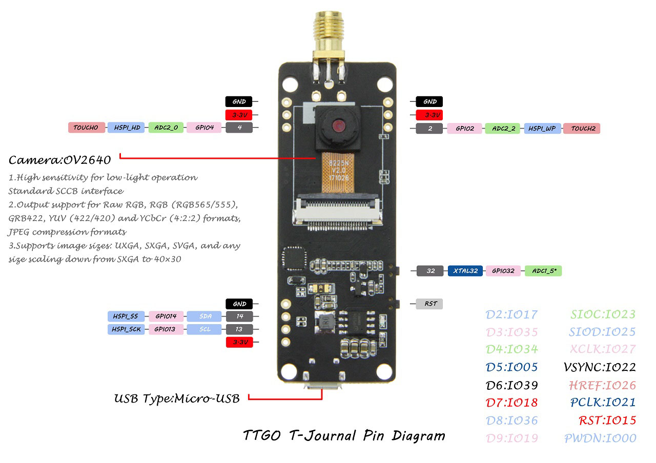
TTGO T-Journal ESP32 Camera Connections
 Here’s a table with the connections between the ESP32 and the camera:
| D2 | GPIO 17 |
| D3 | GPIO 35 |
| D4 | GPIO 34 |
| D5 | GPIO 5 |
| D6 | GPIO 39 |
| D7 | GPIO 18 |
| D8 | GPIO 36 |
| D9 | GPIO 19 |
| SIOC | GPIO 23 |
| SIOD | GPIO 25 |
| XCLK | GPIO 27 |
| VSYNC | GPIO 22 |
| HREF | GPIO 26 |
| PCLK | GPIO 21 |
| RST | GPIO 15 |
| PWDN | GPIO 0 |
TTGO T-Journal ESP32 Board OLED Connections
 This board comes with an I2C SSD1306 0.91 inch OLED display.
To interact with the display you can use the Adafruit SSD1306 , the oled-ssd1306 or other compatible libraries.
We usually use the Adafruit SSD1306 along with the Adafruit_GFX to interact with OLED displays.
The OLED communicates with the ESP32 using the following pins:
This board comes with an I2C SSD1306 0.91 inch OLED display.
To interact with the display you can use the Adafruit SSD1306 , the oled-ssd1306 or other compatible libraries.
We usually use the Adafruit SSD1306 along with the Adafruit_GFX to interact with OLED displays.
The OLED communicates with the ESP32 using the following pins:
| SDA | GPIO 14 |
| SCL | GPIO 13 |
TTGO T-Journal ESP32 Board Control OLED Display
In this section, well show you quick tips on how to control the OLED display of the TTGO T-Journal ESP32 board.
Installing Libraries
To control the OLED display, we’ll use the Adafruit SSD1306 and Adafruit GFX libraries. These libraries can be installed through the Arduino IDE Library Manager. In your Arduino IDE, go toOLED I2C Pins and Display Size
Controlling this OLED display is similar to control a regular 0.96 OLED display connected to an ESP32. The only difference is the way you initialize the display. You need to take into account the I2C pins used by this display (because it doesn’t use the default I2C pins), and the size of the display.Arduino Sketch
To control the OLED display, first, you need to import the required libraries: #include <Wire.h> #include <Adafruit_GFX.h> #include <Adafruit_SSD1306.h> Define the OLED size: #define SCREEN_WIDTH 128 #define SCREEN_HEIGHT 32 Define the I2C pins: #define I2C_SDA 14 #define I2C_SCL 13 Next create an Adafruit_SSD1306 object called display as follows: Adafruit_SSD1306 display(SCREEN_WIDTH, SCREEN_HEIGHT, &Wire, -1); In the setup(), you need to initialize an I2C communication on the I2C pins you’ve defined earlier as follows: Wire.begin(I2C_SDA, I2C_SCL); Then, initialize the OLED display as follows: if(!display.begin(SSD1306_SWITCHCAPVCC, 0x3C, false, false)) { Serial.println(F("SSD1306 allocation failed")); for(;;); } After properly initializing the display, you can use the usual functions to write text and display shapes on the OLED. Read our OLED tutorial with the ESP32 to learn more on how to interact with the OLED display. For testing purposes, you can upload the following code to your board. It simply displays “Hello World”. /* Rui Santos Complete project details at https://RandomNerdTutorials.com/ttgo-t-journal-esp32-camera-getting-started/ Permission is hereby granted, free of charge, to any person obtaining a copy of this software and associated documentation files. The above copyright notice and this permission notice shall be included in all copies or substantial portions of the Software. */ #include <Wire.h> #include <Adafruit_GFX.h> #include <Adafruit_SSD1306.h> #define SCREEN_WIDTH 128 #define SCREEN_HEIGHT 32 #define I2C_SDA 14 #define I2C_SCL 13 Adafruit_SSD1306 display(SCREEN_WIDTH, SCREEN_HEIGHT, &Wire, -1); void setup() { Wire.begin(I2C_SDA, I2C_SCL); if(!display.begin(SSD1306_SWITCHCAPVCC, 0x3C, false, false)) { Serial.println(F("SSD1306 allocation failed")); for(;;); } display.clearDisplay(); display.setTextSize(1); display.setTextColor(WHITE); display.setCursor(0, 0); display.print("Hello World!");; display.display(); } void loop() { // put your main code here, to run repeatedly: } View raw code
TTGO T-Journal ESP32 Camera Projects
We’ve modified some of our existing ESP32-CAM projects to be compatible with the TTGO T-Journal.
Video Streaming Web Server
The following code creates a video streaming web server on the camera IP address. So, you can create an IP CAM that can be integrated in Home Automation platforms like Home Assistant or Node-RED. /* Rui Santos Complete project details at https://RandomNerdTutorials.com/ttgo-t-journal-esp32-camera-getting-started/ Permission is hereby granted, free of charge, to any person obtaining a copy of this software and associated documentation files. The above copyright notice and this permission notice shall be included in all copies or substantial portions of the Software. */ #include "esp_camera.h" #include <WiFi.h> #include "esp_timer.h" #include "img_converters.h" #include "Arduino.h" #include "fb_gfx.h" #include "soc/soc.h" //disable brownout problems #include "soc/rtc_cntl_reg.h" //disable brownout problems #include "esp_http_server.h" #include <Wire.h> #include <Adafruit_GFX.h> #include <Adafruit_SSD1306.h> #define SCREEN_WIDTH 128 #define SCREEN_HEIGHT 32 #define I2C_SDA 14 #define I2C_SCL 13 Adafruit_SSD1306 display(SCREEN_WIDTH, SCREEN_HEIGHT, &Wire, -1); //Replace with your network credentials const char* ssid = "REPLACE_WITH_YOUR_SSID"; const char* password = "REPLACE_WITH_YOUR_PASSWORD"; #define PART_BOUNDARY "123456789000000000000987654321" // OV2640 camera module pins (CAMERA_MODEL_TTGO-T-Journal) #define PWDN_GPIO_NUM 32 #define RESET_GPIO_NUM -1 #define XCLK_GPIO_NUM 27 #define SIOD_GPIO_NUM 25 #define SIOC_GPIO_NUM 23 #define Y9_GPIO_NUM 19 #define Y8_GPIO_NUM 36 #define Y7_GPIO_NUM 18 #define Y6_GPIO_NUM 39 #define Y5_GPIO_NUM 5 #define Y4_GPIO_NUM 34 #define Y3_GPIO_NUM 35 #define Y2_GPIO_NUM 17 #define VSYNC_GPIO_NUM 22 #define HREF_GPIO_NUM 26 #define PCLK_GPIO_NUM 21 static const char* _STREAM_CONTENT_TYPE = "multipart/x-mixed-replace;boundary=" PART_BOUNDARY; static const char* _STREAM_BOUNDARY = "\r\n--" PART_BOUNDARY "\r\n"; static const char* _STREAM_PART = "Content-Type: image/jpeg\r\nContent-Length: %u\r\n\r\n"; httpd_handle_t stream_httpd = NULL; static esp_err_t stream_handler(httpd_req_t *req){ camera_fb_t * fb = NULL; esp_err_t res = ESP_OK; size_t _jpg_buf_len = 0; uint8_t * _jpg_buf = NULL; char * part_buf[64]; res = httpd_resp_set_type(req, _STREAM_CONTENT_TYPE); if(res != ESP_OK){ return res; } while(true){ fb = esp_camera_fb_get(); if (!fb) { Serial.println("Camera capture failed"); res = ESP_FAIL; } else { if(fb->width > 400){ if(fb->format != PIXFORMAT_JPEG){ bool jpeg_converted = frame2jpg(fb, 80, &_jpg_buf, &_jpg_buf_len); esp_camera_fb_return(fb); fb = NULL; if(!jpeg_converted){ Serial.println("JPEG compression failed"); res = ESP_FAIL; } } else { _jpg_buf_len = fb->len; _jpg_buf = fb->buf; } } } if(res == ESP_OK){ size_t hlen = snprintf((char *)part_buf, 64, _STREAM_PART, _jpg_buf_len); res = httpd_resp_send_chunk(req, (const char *)part_buf, hlen); } if(res == ESP_OK){ res = httpd_resp_send_chunk(req, (const char *)_jpg_buf, _jpg_buf_len); } if(res == ESP_OK){ res = httpd_resp_send_chunk(req, _STREAM_BOUNDARY, strlen(_STREAM_BOUNDARY)); } if(fb){ esp_camera_fb_return(fb); fb = NULL; _jpg_buf = NULL; } else if(_jpg_buf){ free(_jpg_buf); _jpg_buf = NULL; } if(res != ESP_OK){ break; } //Serial.printf("MJPG: %uB\n",(uint32_t)(_jpg_buf_len)); } return res; } void startCameraServer(){ httpd_config_t config = HTTPD_DEFAULT_CONFIG(); config.server_port = 80; httpd_uri_t index_uri = { .uri = "/", .method = HTTP_GET, .handler = stream_handler, .user_ctx = NULL }; //Serial.printf("Starting web server on port: '%d'\n", config.server_port); if (httpd_start(&stream_httpd, &config) == ESP_OK) { httpd_register_uri_handler(stream_httpd, &index_uri); } } void setup() { WRITE_PERI_REG(RTC_CNTL_BROWN_OUT_REG, 0); //disable brownout detector Serial.begin(115200); Serial.setDebugOutput(false); camera_config_t config; config.ledc_channel = LEDC_CHANNEL_0; config.ledc_timer = LEDC_TIMER_0; config.pin_d0 = Y2_GPIO_NUM; config.pin_d1 = Y3_GPIO_NUM; config.pin_d2 = Y4_GPIO_NUM; config.pin_d3 = Y5_GPIO_NUM; config.pin_d4 = Y6_GPIO_NUM; config.pin_d5 = Y7_GPIO_NUM; config.pin_d6 = Y8_GPIO_NUM; config.pin_d7 = Y9_GPIO_NUM; config.pin_xclk = XCLK_GPIO_NUM; config.pin_pclk = PCLK_GPIO_NUM; config.pin_vsync = VSYNC_GPIO_NUM; config.pin_href = HREF_GPIO_NUM; config.pin_sscb_sda = SIOD_GPIO_NUM; config.pin_sscb_scl = SIOC_GPIO_NUM; config.pin_pwdn = PWDN_GPIO_NUM; config.pin_reset = RESET_GPIO_NUM; config.xclk_freq_hz = 20000000; config.pixel_format = PIXFORMAT_JPEG; if(psramFound()){ config.frame_size = FRAMESIZE_UXGA; config.jpeg_quality = 10; config.fb_count = 2; } else { config.frame_size = FRAMESIZE_SVGA; config.jpeg_quality = 12; config.fb_count = 1; } // Camera init esp_err_t err = esp_camera_init(&config); if (err != ESP_OK) { Serial.printf("Camera init failed with error 0x%x", err); return; } // Wi-Fi connection WiFi.begin(ssid, password); while (WiFi.status() != WL_CONNECTED) { delay(500); Serial.print("."); } Serial.println(""); Serial.println("WiFi connected"); Serial.print("Camera Stream Ready! Go to: http://"); Serial.print(WiFi.localIP()); // Init OLED Wire.begin(I2C_SDA, I2C_SCL); if(!display.begin(SSD1306_SWITCHCAPVCC, 0x3C, false, false)) { Serial.println(F("SSD1306 allocation failed")); for(;;); } display.clearDisplay(); display.setTextSize(1); display.setTextColor(WHITE); display.setCursor(5, 5); display.print(WiFi.localIP());; display.display(); // Start streaming web server startCameraServer(); } void loop() { delay(1); } View raw code
Learn more about this project: ESP32-CAM Video Streaming Web Server
Take Photo and Display in Web Server
The following code creates a web server that you can access to take and display photos. The web server IP address is displayed on the OLED. /* Rui Santos Complete project details at https://RandomNerdTutorials.com/ttgo-t-journal-esp32-camera-getting-started/ Permission is hereby granted, free of charge, to any person obtaining a copy of this software and associated documentation files. The above copyright notice and this permission notice shall be included in all copies or substantial portions of the Software. */ #include "WiFi.h" #include "esp_camera.h" #include "esp_timer.h" #include "img_converters.h" #include "Arduino.h" #include "soc/soc.h" // Disable brownour problems #include "soc/rtc_cntl_reg.h" // Disable brownour problems #include "driver/rtc_io.h" #include <ESPAsyncWebServer.h> #include <StringArray.h> #include <SPIFFS.h> #include <FS.h> #include <Wire.h> #include <Adafruit_GFX.h> #include <Adafruit_SSD1306.h> #define SCREEN_WIDTH 128 #define SCREEN_HEIGHT 32 #define I2C_SDA 14 #define I2C_SCL 13 Adafruit_SSD1306 display(SCREEN_WIDTH, SCREEN_HEIGHT, &Wire, -1); // Replace with your network credentials const char* ssid = "REPLACE_WITH_YOUR_SSID"; const char* password = "REPLACE_WITH_YOUR_PASSWORD"; // Create AsyncWebServer object on port 80 AsyncWebServer server(80); boolean takeNewPhoto = false; // Photo File Name to save in SPIFFS #define FILE_PHOTO "/photo.jpg" // OV2640 camera module pins (CAMERA_MODEL_TTGO-T-Journal) #define PWDN_GPIO_NUM 32 #define RESET_GPIO_NUM -1 #define XCLK_GPIO_NUM 27 #define SIOD_GPIO_NUM 25 #define SIOC_GPIO_NUM 23 #define Y9_GPIO_NUM 19 #define Y8_GPIO_NUM 36 #define Y7_GPIO_NUM 18 #define Y6_GPIO_NUM 39 #define Y5_GPIO_NUM 5 #define Y4_GPIO_NUM 34 #define Y3_GPIO_NUM 35 #define Y2_GPIO_NUM 17 #define VSYNC_GPIO_NUM 22 #define HREF_GPIO_NUM 26 #define PCLK_GPIO_NUM 21 const char index_html[] PROGMEM = R"rawliteral( <!DOCTYPE HTML><html> <head> <meta name="viewport" content="width=device-width, initial-scale=1"> <style> body { text-align:center; } .vert { margin-bottom: 10%; } .hori{ margin-bottom: 0%; } </style> </head> <body> <div> <h2>ESP32-CAM Last Photo</h2> <p>It might take more than 5 seconds to capture a photo.</p> <p> <button onclick="rotatePhoto();">ROTATE</button> <button onclick="capturePhoto()">CAPTURE PHOTO</button> <button onclick="location.reload();">REFRESH PAGE</button> </p> </div> <div><img src="saved-photo"></div> </body> <script> var deg = 0; function capturePhoto() { var xhr = new XMLHttpRequest(); xhr.open('GET', "/capture", true); xhr.send(); } function rotatePhoto() { var img = document.getElementById("photo"); deg += 90; if(isOdd(deg/90)){ document.getElementById("container").className = "vert"; } else{ document.getElementById("container").className = "hori"; } img.style.transform = "rotate(" + deg + "deg)"; } function isOdd(n) { return Math.abs(n % 2) == 1; } </script> </html>)rawliteral"; void setup() { // Serial port for debugging purposes Serial.begin(115200); // Connect to Wi-Fi WiFi.begin(ssid, password); while (WiFi.status() != WL_CONNECTED) { delay(1000); Serial.println("Connecting to WiFi..."); } if (!SPIFFS.begin(true)) { Serial.println("An Error has occurred while mounting SPIFFS"); ESP.restart(); } else { delay(500); Serial.println("SPIFFS mounted successfully"); } // Print ESP32 Local IP Address Serial.print("IP Address: http://"); Serial.println(WiFi.localIP()); // Init OLED Wire.begin(I2C_SDA, I2C_SCL); if(!display.begin(SSD1306_SWITCHCAPVCC, 0x3C, false, false)) { Serial.println(F("SSD1306 allocation failed")); for(;;); } display.clearDisplay(); display.setTextSize(1); display.setTextColor(WHITE); display.setCursor(5, 5); display.print(WiFi.localIP());; display.display(); // Turn-off the 'brownout detector' WRITE_PERI_REG(RTC_CNTL_BROWN_OUT_REG, 0); // OV2640 camera module camera_config_t config; config.ledc_channel = LEDC_CHANNEL_0; config.ledc_timer = LEDC_TIMER_0; config.pin_d0 = Y2_GPIO_NUM; config.pin_d1 = Y3_GPIO_NUM; config.pin_d2 = Y4_GPIO_NUM; config.pin_d3 = Y5_GPIO_NUM; config.pin_d4 = Y6_GPIO_NUM; config.pin_d5 = Y7_GPIO_NUM; config.pin_d6 = Y8_GPIO_NUM; config.pin_d7 = Y9_GPIO_NUM; config.pin_xclk = XCLK_GPIO_NUM; config.pin_pclk = PCLK_GPIO_NUM; config.pin_vsync = VSYNC_GPIO_NUM; config.pin_href = HREF_GPIO_NUM; config.pin_sscb_sda = SIOD_GPIO_NUM; config.pin_sscb_scl = SIOC_GPIO_NUM; config.pin_pwdn = PWDN_GPIO_NUM; config.pin_reset = RESET_GPIO_NUM; config.xclk_freq_hz = 20000000; config.pixel_format = PIXFORMAT_JPEG; if (psramFound()) { config.frame_size = FRAMESIZE_UXGA; config.jpeg_quality = 10; config.fb_count = 2; } else { config.frame_size = FRAMESIZE_SVGA; config.jpeg_quality = 12; config.fb_count = 1; } // Camera init esp_err_t err = esp_camera_init(&config); if (err != ESP_OK) { Serial.printf("Camera init failed with error 0x%x", err); ESP.restart(); } // Route for root / web page server.on("/", HTTP_GET, [](AsyncWebServerRequest * request) { request->send_P(200, "text/html", index_html); }); server.on("/capture", HTTP_GET, [](AsyncWebServerRequest * request) { takeNewPhoto = true; request->send_P(200, "text/plain", "Taking Photo"); }); server.on("/saved-photo", HTTP_GET, [](AsyncWebServerRequest * request) { request->send(SPIFFS, FILE_PHOTO, "image/jpg", false); }); // Start server server.begin(); } void loop() { if (takeNewPhoto) { capturePhotoSaveSpiffs(); takeNewPhoto = false; } delay(1); } // Check if photo capture was successful bool checkPhoto( fs::FS &fs ) { File f_pic = fs.open( FILE_PHOTO ); unsigned int pic_sz = f_pic.size(); return ( pic_sz > 100 ); } // Capture Photo and Save it to SPIFFS void capturePhotoSaveSpiffs( void ) { camera_fb_t * fb = NULL; // pointer bool ok = 0; // Boolean indicating if the picture has been taken correctly do { // Take a photo with the camera Serial.println("Taking a photo..."); fb = esp_camera_fb_get(); if (!fb) { Serial.println("Camera capture failed"); return; } // Photo file name Serial.printf("Picture file name: %s\n", FILE_PHOTO); File file = SPIFFS.open(FILE_PHOTO, FILE_WRITE); // Insert the data in the photo file if (!file) { Serial.println("Failed to open file in writing mode"); } else { file.write(fb->buf, fb->len); // payload (image), payload length Serial.print("The picture has been saved in "); Serial.print(FILE_PHOTO); Serial.print(" - Size: "); Serial.print(file.size()); Serial.println(" bytes"); } // Close the file file.close(); esp_camera_fb_return(fb); // check if file has been correctly saved in SPIFFS ok = checkPhoto(SPIFFS); } while ( !ok ); } View raw code
Learn more about this project: ESP32-CAM Take Photo and Display in Web Server
CameraWebServer Example
You can also run the default CameraWebServer example that comes with the Arduino IDE. In your Arduino IDE, go to Copy the following to the camera_pins.h file.
#if defined(CAMERA_MODEL_T_JOURNAL)
#define PWDN_GPIO_NUM 32
#define RESET_GPIO_NUM -1
#define XCLK_GPIO_NUM 27
#define SIOD_GPIO_NUM 25
#define SIOC_GPIO_NUM 23
#define Y9_GPIO_NUM 19
#define Y8_GPIO_NUM 36
#define Y7_GPIO_NUM 18
#define Y6_GPIO_NUM 39
#define Y5_GPIO_NUM 5
#define Y4_GPIO_NUM 34
#define Y3_GPIO_NUM 35
#define Y2_GPIO_NUM 17
#define VSYNC_GPIO_NUM 22
#define HREF_GPIO_NUM 26
#define PCLK_GPIO_NUM 21
Then, in the CameraWebServer tab, comment all the existing camera models, and add your camera, as follows:
// Select camera model
#define CAMERA_MODEL_T_JOURNAL
//#define CAMERA_MODEL_WROVER_KIT
//#define CAMERA_MODEL_ESP_EYE
//#define CAMERA_MODEL_M5STACK_PSRAM
//#define CAMERA_MODEL_M5STACK_WIDE
//#define CAMERA_MODEL_AI_THINKER
Because this camera doesn’t have PSRAM, the face recognition and detection features of this project don’t work with this camera.
All the other functionalities work well.
Copy the following to the camera_pins.h file.
#if defined(CAMERA_MODEL_T_JOURNAL)
#define PWDN_GPIO_NUM 32
#define RESET_GPIO_NUM -1
#define XCLK_GPIO_NUM 27
#define SIOD_GPIO_NUM 25
#define SIOC_GPIO_NUM 23
#define Y9_GPIO_NUM 19
#define Y8_GPIO_NUM 36
#define Y7_GPIO_NUM 18
#define Y6_GPIO_NUM 39
#define Y5_GPIO_NUM 5
#define Y4_GPIO_NUM 34
#define Y3_GPIO_NUM 35
#define Y2_GPIO_NUM 17
#define VSYNC_GPIO_NUM 22
#define HREF_GPIO_NUM 26
#define PCLK_GPIO_NUM 21
Then, in the CameraWebServer tab, comment all the existing camera models, and add your camera, as follows:
// Select camera model
#define CAMERA_MODEL_T_JOURNAL
//#define CAMERA_MODEL_WROVER_KIT
//#define CAMERA_MODEL_ESP_EYE
//#define CAMERA_MODEL_M5STACK_PSRAM
//#define CAMERA_MODEL_M5STACK_WIDE
//#define CAMERA_MODEL_AI_THINKER
Because this camera doesn’t have PSRAM, the face recognition and detection features of this project don’t work with this camera.
All the other functionalities work well.
Upload Code to the TTGO T-Journal ESP32 Camera
To upload code, you just need to connect the board to your computer, then in the Arduino IDE, go to  Then, simply click the Arduino IDE upload button and it is done!
[eBook] Build ESP32-CAM Projects using Arduino IDE
Learn how to program and build 17 projects with the ESP32-CAM using Arduino IDEWrapping Up
This tutorial was a quick getting started guide for the TTGO T-Journal ESP32 Camera Development board.
You’ve learned how to control the OLED display and how to adapt existing ESP32 camera projects to your board.
We hope you’ve found this tutorial useful.
To learn more about this board, you can read our complete overview on Maker Advisor as well as our ESP32-CAM development boards comparison post:
TTGO T-Journal ESP32 Camera Board Review and Documentation (Pinout, Features, etc…)
ESP32 Camera Dev Boards Review and Comparison (Best ESP32-CAM)
You may also be interested in other ESP32 development boards:
$7 ESP32-CAM with OV2640 Camera (Review)
ESP32 with Built-in SX1276 LoRa and SSD1306 OLED Display (Review)
$11 TTGO T-Call ESP32 with SIM800L GSM/GPRS (Overview)
10 IoT Development Boards You Need to Get
Best ESP32 Development Boards
Visualize Your Sensor Readings from Anywhere in the World (ESP32/ESP8266 + MySQL + PHP)
In this project, you’ll create a web page that displays sensor readings in a plot that you can access from anywhere in the world. In summary, you’ll build an ESP32 or ESP8266 client that makes a request to a PHP script to publish sensor readings in a MySQL database. Updated on 26 March 2023
As an example, we’ll be using a BME280 sensor connected to an ESP board.
You can modify the code provided to send readings from a different sensor or use multiple boards.
To create this project, you’ll use these technologies:
ESP32 or ESP8266 programmed with Arduino IDE
Hosting server and domain name
PHP script to insert data into MySQL database and display it on a web page
MySQL database to store readings
PHP script to plot data from database in charts
You might also find helpful reading these projects:
ESP32/ESP8266 Insert Data into MySQL Database using PHP and Arduino IDE
ESP32/ESP8266 Plot Sensor Readings in Real Time Charts – Web Server
The project is divided into the following main sections:
Updated on 26 March 2023
As an example, we’ll be using a BME280 sensor connected to an ESP board.
You can modify the code provided to send readings from a different sensor or use multiple boards.
To create this project, you’ll use these technologies:
ESP32 or ESP8266 programmed with Arduino IDE
Hosting server and domain name
PHP script to insert data into MySQL database and display it on a web page
MySQL database to store readings
PHP script to plot data from database in charts
You might also find helpful reading these projects:
ESP32/ESP8266 Insert Data into MySQL Database using PHP and Arduino IDE
ESP32/ESP8266 Plot Sensor Readings in Real Time Charts – Web Server
The project is divided into the following main sections:
Watch the Video Demonstration
To see how the project works, you can watch the following video demonstration:
1.Hosting Your PHP Application and MySQL Database
The goal of this project is to have your own domain name and hosting account that allows you to store sensor readings from the ESP32 or ESP8266. You can visualize the readings from anywhere in the world by accessing your own server domain. Here’s a high level overview of the project: I recommend using one of the following hosting services that can handle all the project requirements:
Bluehost (user-friendly with cPanel) : free domain name when you sign up for the 3-year plan.
I recommend choosing the unlimited websites option;
Digital Ocean : Linux server that you manage through a command line.
I only recommended this option for advanced users.
Those two services are the ones that I use and personally recommend, but you can use any other hosting service.
Any hosting service that offers PHP and MySQL will work with this tutorial.
If you don’t have a hosting account, I recommend signing up for Bluehost .
Get Hosting and Domain Name with Bluehost
When buying a hosting account, you’ll also have to purchase a domain name.
This is what makes this project interesting: you’ll be able to go your domain name (http://example.com) and see your ESP readings.
If you like our projects, you might consider signing up to one of the recommended hosting services, because you’ll be supporting our work.
I recommend using one of the following hosting services that can handle all the project requirements:
Bluehost (user-friendly with cPanel) : free domain name when you sign up for the 3-year plan.
I recommend choosing the unlimited websites option;
Digital Ocean : Linux server that you manage through a command line.
I only recommended this option for advanced users.
Those two services are the ones that I use and personally recommend, but you can use any other hosting service.
Any hosting service that offers PHP and MySQL will work with this tutorial.
If you don’t have a hosting account, I recommend signing up for Bluehost .
Get Hosting and Domain Name with Bluehost
When buying a hosting account, you’ll also have to purchase a domain name.
This is what makes this project interesting: you’ll be able to go your domain name (http://example.com) and see your ESP readings.
If you like our projects, you might consider signing up to one of the recommended hosting services, because you’ll be supporting our work.
2.Preparing Your MySQL Database
After signing up for a hosting account and setting up a domain name , you can login to your cPanel or similar dashboard. After that, follow the next steps to create your database, username, password and SQL table.Creating a database and user
Open the “
That’s it! Your new database and user were created successfully.
Now, save all your details because you’ll need them later:
Creating a SQL table
After creating your database and user, go back to cPanel dashboard and search for “phpMyAdmin”.
In the left sidebar, select your database name example_esp_data and open the “SQL” tab.
 After that, you should see your newly created table called Sensor in the example_esp_data database as shown in the figure below:
3.PHP Script HTTP POST – Insert Data in MySQL Databa3e
In this section, we’re going to create a PHP script that receives incoming requests from the ESP32 or ESP8266 and inserts the data into a MySQL database.
If you’re using a hosting provider with cPanel, you can search for “File Manager”:
Then, select the public_html option and press the “+ File” button to create a new .php file.

Note: if you’re following this tutorial and you’re not familiar with PHP or MySQL, I recommend creating these exact files.
Otherwise, you’ll need to modify the ESP sketch provided with different URL paths.
Create a new file in /public_html with this exact name and extension: post-data.php
 Edit the newly created file (post-data.php) and copy the following snippet:
<?php
/*
Rui Santos
Complete project details at https://RandomNerdTutorials.com
Permission is hereby granted, free of charge, to any person obtaining a copy
of this software and associated documentation files.
The above copyright notice and this permission notice shall be included in all
copies or substantial portions of the Software.
*/
$servername = "localhost";
// REPLACE with your Database name
$dbname = "REPLACE_WITH_YOUR_DATABASE_NAME";
// REPLACE with Database user
$username = "REPLACE_WITH_YOUR_USERNAME";
// REPLACE with Database user password
$password = "REPLACE_WITH_YOUR_PASSWORD";
// Keep this API Key value to be compatible with the ESP32 code provided in the project page.
If you change this value, the ESP32 sketch needs to match
$api_key_value = "tPmAT5Ab3j7F9";
$api_key = $value1 = $value2 = $value3 = "";
if ($_SERVER["REQUEST_METHOD"] == "POST") {
$api_key = test_input($_POST["api_key"]);
if($api_key == $api_key_value) {
$value1 = test_input($_POST["value1"]);
$value2 = test_input($_POST["value2"]);
$value3 = test_input($_POST["value3"]);
// Create connection
$conn = new mysqli($servername, $username, $password, $dbname);
// Check connection
if ($conn->connect_error) {
die("Connection failed: " .
$conn->connect_error);
}
$sql = "INSERT INTO Sensor (value1, value2, value3)
VALUES ('" .
$value1 .
"', '" .
$value2 .
"', '" .
$value3 .
"')";
if ($conn->query($sql) === TRUE) {
echo "New record created successfully";
}
else {
echo "Error: " .
$sql .
"<br>" .
$conn->error;
}
$conn->close();
}
else {
echo "Wrong API Key provided.";
}
}
else {
echo "No data posted with HTTP POST.";
}
function test_input($data) {
$data = trim($data);
$data = stripslashes($data);
$data = htmlspecialchars($data);
return $data;
}
View raw code
Before saving the file, you need to modify the $dbname, $username and $password variables with your unique details:
// Your Database name
$dbname = "example_esp_data";
// Your Database user
$username = "example_esp_board";
// Your Database user password
$password = "YOUR_USER_PASSWORD";
After adding the database name, username and password, save the file and continue with this tutorial.
If you try to access your domain name in the next URL path, you’ll see the message:
http://example.com/post-data.php
Edit the newly created file (post-data.php) and copy the following snippet:
<?php
/*
Rui Santos
Complete project details at https://RandomNerdTutorials.com
Permission is hereby granted, free of charge, to any person obtaining a copy
of this software and associated documentation files.
The above copyright notice and this permission notice shall be included in all
copies or substantial portions of the Software.
*/
$servername = "localhost";
// REPLACE with your Database name
$dbname = "REPLACE_WITH_YOUR_DATABASE_NAME";
// REPLACE with Database user
$username = "REPLACE_WITH_YOUR_USERNAME";
// REPLACE with Database user password
$password = "REPLACE_WITH_YOUR_PASSWORD";
// Keep this API Key value to be compatible with the ESP32 code provided in the project page.
If you change this value, the ESP32 sketch needs to match
$api_key_value = "tPmAT5Ab3j7F9";
$api_key = $value1 = $value2 = $value3 = "";
if ($_SERVER["REQUEST_METHOD"] == "POST") {
$api_key = test_input($_POST["api_key"]);
if($api_key == $api_key_value) {
$value1 = test_input($_POST["value1"]);
$value2 = test_input($_POST["value2"]);
$value3 = test_input($_POST["value3"]);
// Create connection
$conn = new mysqli($servername, $username, $password, $dbname);
// Check connection
if ($conn->connect_error) {
die("Connection failed: " .
$conn->connect_error);
}
$sql = "INSERT INTO Sensor (value1, value2, value3)
VALUES ('" .
$value1 .
"', '" .
$value2 .
"', '" .
$value3 .
"')";
if ($conn->query($sql) === TRUE) {
echo "New record created successfully";
}
else {
echo "Error: " .
$sql .
"<br>" .
$conn->error;
}
$conn->close();
}
else {
echo "Wrong API Key provided.";
}
}
else {
echo "No data posted with HTTP POST.";
}
function test_input($data) {
$data = trim($data);
$data = stripslashes($data);
$data = htmlspecialchars($data);
return $data;
}
View raw code
Before saving the file, you need to modify the $dbname, $username and $password variables with your unique details:
// Your Database name
$dbname = "example_esp_data";
// Your Database user
$username = "example_esp_board";
// Your Database user password
$password = "YOUR_USER_PASSWORD";
After adding the database name, username and password, save the file and continue with this tutorial.
If you try to access your domain name in the next URL path, you’ll see the message:
http://example.com/post-data.php

4.PHP Script – Visualize Database Content in a Chart3/h2>
Create another PHP file in the /public_html directory that will plot the database content in a chart on a web page.
Name your new file: esp-chart.php
 Edit the newly created file (esp-chart.php) and copy the following code:
<!--
Rui Santos
Complete project details at https://RandomNerdTutorials.com
Permission is hereby granted, free of charge, to any person obtaining a copy
of this software and associated documentation files.
The above copyright notice and this permission notice shall be included in all
copies or substantial portions of the Software.
-->
<?php
$servername = "localhost";
// REPLACE with your Database name
$dbname = "REPLACE_WITH_YOUR_DATABASE_NAME";
// REPLACE with Database user
$username = "REPLACE_WITH_YOUR_USERNAME";
// REPLACE with Database user password
$password = "REPLACE_WITH_YOUR_PASSWORD";
// Create connection
$conn = new mysqli($servername, $username, $password, $dbname);
// Check connection
if ($conn->connect_error) {
die("Connection failed: " .
$conn->connect_error);
}
$sql = "SELECT id, value1, value2, value3, reading_time FROM Sensor order by reading_time desc limit 40";
$result = $conn->query($sql);
while ($data = $result->fetch_assoc()){
$sensor_data[] = $data;
}
$readings_time = array_column($sensor_data, 'reading_time');
// ******* Uncomment to convert readings time array to your timezone ********
/*$i = 0;
foreach ($readings_time as $reading){
// Uncomment to set timezone to - 1 hour (you can change 1 to any number)
$readings_time[$i] = date("Y-m-d H:i:s", strtotime("$reading - 1 hours"));
// Uncomment to set timezone to + 4 hours (you can change 4 to any number)
//$readings_time[$i] = date("Y-m-d H:i:s", strtotime("$reading + 4 hours"));
$i += 1;
}*/
$value1 = json_encode(array_reverse(array_column($sensor_data, 'value1')), JSON_NUMERIC_CHECK);
$value2 = json_encode(array_reverse(array_column($sensor_data, 'value2')), JSON_NUMERIC_CHECK);
$value3 = json_encode(array_reverse(array_column($sensor_data, 'value3')), JSON_NUMERIC_CHECK);
$reading_time = json_encode(array_reverse($readings_time), JSON_NUMERIC_CHECK);
/*echo $value1;
echo $value2;
echo $value3;
echo $reading_time;*/
$result->free();
$conn->close();
?>
<!DOCTYPE html>
<html>
<meta name="viewport" content="width=device-width, initial-scale=1">
<script src="https://code.highcharts.com/highcharts.js"></script>
<style>
body {
min-width: 310px;
max-width: 1280px;
height: 500px;
margin: 0 auto;
}
h2 {
font-family: Arial;
font-size: 2.5rem;
text-align: center;
}
</style>
<body>
<h2>ESP Weather Station</h2>
<div></div>
<div></div>
<div></div>
<script>
var value1 = <?php echo $value1; ?>;
var value2 = <?php echo $value2; ?>;
var value3 = <?php echo $value3; ?>;
var reading_time = <?php echo $reading_time; ?>;
var chartT = new Highcharts.Chart({
chart:{ renderTo : 'chart-temperature' },
title: { text: 'BME280 Temperature' },
series: [{
showInLegend: false,
data: value1
}],
plotOptions: {
line: { animation: false,
dataLabels: { enabled: true }
},
series: { color: '#059e8a' }
},
xAxis: {
type: 'datetime',
categories: reading_time
},
yAxis: {
title: { text: 'Temperature (Celsius)' }
//title: { text: 'Temperature (Fahrenheit)' }
},
credits: { enabled: false }
});
var chartH = new Highcharts.Chart({
chart:{ renderTo:'chart-humidity' },
title: { text: 'BME280 Humidity' },
series: [{
showInLegend: false,
data: value2
}],
plotOptions: {
line: { animation: false,
dataLabels: { enabled: true }
}
},
xAxis: {
type: 'datetime',
//dateTimeLabelFormats: { second: '%H:%M:%S' },
categories: reading_time
},
yAxis: {
title: { text: 'Humidity (%)' }
},
credits: { enabled: false }
});
var chartP = new Highcharts.Chart({
chart:{ renderTo:'chart-pressure' },
title: { text: 'BME280 Pressure' },
series: [{
showInLegend: false,
data: value3
}],
plotOptions: {
line: { animation: false,
dataLabels: { enabled: true }
},
series: { color: '#18009c' }
},
xAxis: {
type: 'datetime',
categories: reading_time
},
yAxis: {
title: { text: 'Pressure (hPa)' }
},
credits: { enabled: false }
});
</script>
</body>
</html>
View raw code
After adding the $dbname, $username and $password save the file and continue with this project.
// Your Database name
$dbname = "example_esp_data";
// Your Database user
$username = "example_esp_board";
// Your Database user password
$password = "YOUR_USER_PASSWORD";
If you try to access your domain name in the following URL path, you’ll see the following:
https://example.com/esp-chart.php
Edit the newly created file (esp-chart.php) and copy the following code:
<!--
Rui Santos
Complete project details at https://RandomNerdTutorials.com
Permission is hereby granted, free of charge, to any person obtaining a copy
of this software and associated documentation files.
The above copyright notice and this permission notice shall be included in all
copies or substantial portions of the Software.
-->
<?php
$servername = "localhost";
// REPLACE with your Database name
$dbname = "REPLACE_WITH_YOUR_DATABASE_NAME";
// REPLACE with Database user
$username = "REPLACE_WITH_YOUR_USERNAME";
// REPLACE with Database user password
$password = "REPLACE_WITH_YOUR_PASSWORD";
// Create connection
$conn = new mysqli($servername, $username, $password, $dbname);
// Check connection
if ($conn->connect_error) {
die("Connection failed: " .
$conn->connect_error);
}
$sql = "SELECT id, value1, value2, value3, reading_time FROM Sensor order by reading_time desc limit 40";
$result = $conn->query($sql);
while ($data = $result->fetch_assoc()){
$sensor_data[] = $data;
}
$readings_time = array_column($sensor_data, 'reading_time');
// ******* Uncomment to convert readings time array to your timezone ********
/*$i = 0;
foreach ($readings_time as $reading){
// Uncomment to set timezone to - 1 hour (you can change 1 to any number)
$readings_time[$i] = date("Y-m-d H:i:s", strtotime("$reading - 1 hours"));
// Uncomment to set timezone to + 4 hours (you can change 4 to any number)
//$readings_time[$i] = date("Y-m-d H:i:s", strtotime("$reading + 4 hours"));
$i += 1;
}*/
$value1 = json_encode(array_reverse(array_column($sensor_data, 'value1')), JSON_NUMERIC_CHECK);
$value2 = json_encode(array_reverse(array_column($sensor_data, 'value2')), JSON_NUMERIC_CHECK);
$value3 = json_encode(array_reverse(array_column($sensor_data, 'value3')), JSON_NUMERIC_CHECK);
$reading_time = json_encode(array_reverse($readings_time), JSON_NUMERIC_CHECK);
/*echo $value1;
echo $value2;
echo $value3;
echo $reading_time;*/
$result->free();
$conn->close();
?>
<!DOCTYPE html>
<html>
<meta name="viewport" content="width=device-width, initial-scale=1">
<script src="https://code.highcharts.com/highcharts.js"></script>
<style>
body {
min-width: 310px;
max-width: 1280px;
height: 500px;
margin: 0 auto;
}
h2 {
font-family: Arial;
font-size: 2.5rem;
text-align: center;
}
</style>
<body>
<h2>ESP Weather Station</h2>
<div></div>
<div></div>
<div></div>
<script>
var value1 = <?php echo $value1; ?>;
var value2 = <?php echo $value2; ?>;
var value3 = <?php echo $value3; ?>;
var reading_time = <?php echo $reading_time; ?>;
var chartT = new Highcharts.Chart({
chart:{ renderTo : 'chart-temperature' },
title: { text: 'BME280 Temperature' },
series: [{
showInLegend: false,
data: value1
}],
plotOptions: {
line: { animation: false,
dataLabels: { enabled: true }
},
series: { color: '#059e8a' }
},
xAxis: {
type: 'datetime',
categories: reading_time
},
yAxis: {
title: { text: 'Temperature (Celsius)' }
//title: { text: 'Temperature (Fahrenheit)' }
},
credits: { enabled: false }
});
var chartH = new Highcharts.Chart({
chart:{ renderTo:'chart-humidity' },
title: { text: 'BME280 Humidity' },
series: [{
showInLegend: false,
data: value2
}],
plotOptions: {
line: { animation: false,
dataLabels: { enabled: true }
}
},
xAxis: {
type: 'datetime',
//dateTimeLabelFormats: { second: '%H:%M:%S' },
categories: reading_time
},
yAxis: {
title: { text: 'Humidity (%)' }
},
credits: { enabled: false }
});
var chartP = new Highcharts.Chart({
chart:{ renderTo:'chart-pressure' },
title: { text: 'BME280 Pressure' },
series: [{
showInLegend: false,
data: value3
}],
plotOptions: {
line: { animation: false,
dataLabels: { enabled: true }
},
series: { color: '#18009c' }
},
xAxis: {
type: 'datetime',
categories: reading_time
},
yAxis: {
title: { text: 'Pressure (hPa)' }
},
credits: { enabled: false }
});
</script>
</body>
</html>
View raw code
After adding the $dbname, $username and $password save the file and continue with this project.
// Your Database name
$dbname = "example_esp_data";
// Your Database user
$username = "example_esp_board";
// Your Database user password
$password = "YOUR_USER_PASSWORD";
If you try to access your domain name in the following URL path, you’ll see the following:
https://example.com/esp-chart.php
 That’s it! If you see three empty charts in your browser, it means that everything is ready.
In the next section, you’ll learn how to publish your ESP32 or ESP8266 sensor readings.
To build the charts, we’ll use the Highcharts library .
We’ll create three charts: temperature, humidity and pressure over time.
The charts display a maximum of 40 data points, and a new reading is added every 30 seconds, but you change these values in your code.
That’s it! If you see three empty charts in your browser, it means that everything is ready.
In the next section, you’ll learn how to publish your ESP32 or ESP8266 sensor readings.
To build the charts, we’ll use the Highcharts library .
We’ll create three charts: temperature, humidity and pressure over time.
The charts display a maximum of 40 data points, and a new reading is added every 30 seconds, but you change these values in your code.
5.Setting up the ESP32 or ESP8266
This project is compatible with both the ESP32 and ESP8266 boards.
You just need to assemble a simple circuit and upload the sketch provided to insert temperature, humidity, pressure, and more into your database every 30 seconds.
The sketch is slightly different for each board.
Parts Required
For this example, we’ll get sensor readings from the BME280 sensor.
Here’s a list of parts you need to build the circuit for this project:
ESP32 board (read Best ESP32 dev boards )
Alternative – ESP8266 board (read Best ESP8266 dev boards )
BME280 sensor
Jumper wires
Breadboard
Schematics
The BME280 sensor module we’re using communicates via I2C communication protocol, so you need to connect it to the ESP32 or ESP8266 I2C pins.
BME280 wiring to ESP32
The ESP32 I2C pins are:
GPIO 22: SCL (SCK)
GPIO 21: SDA (SDI)
So, assemble your circuit as shown in the next schematic diagram ( read complete Guide for ESP32 with BME280 ).
Recommended reading: ESP32 Pinout Reference Guide
BME280 wiring to ESP8266
The ESP8266 I2C pins are:
GPIO 5 (D1): SCL (SCK)
GPIO 4 (D2): SDA (SDI)
Assemble your circuit as in the next schematic diagram if you’re using an ESP8266 board ( read complete Guide for ESP8266 with BME280 ).
Recommended reading: ESP8266 Pinout Reference Guide
Installing Libraries
We’ll program the ESP32/ESP8266 using Arduino IDE, so you must have the ESP32/ESP8266 add-on installed in your Arduino IDE.
Follow one of the next tutorials depending on the board you’re using:
Install the ESP32 Board in Arduino IDE – you also need to install the BME280 Library and Adafruit_Sensor library
Install the ESP8266 Board in Arduino IDE – you also need to install the BME280 Library and Adafruit_Sensor library
ESP32 Code
Follow this section if you’re using an ESP32..
After installing the necessary board add-ons, copy the following code to your Arduino IDE, but don’t upload it yet.
You need to make some changes to make it work for you.
/*
Rui Santos
Complete project details at https://RandomNerdTutorials.com/esp32-esp8266-mysql-database-php/
Permission is hereby granted, free of charge, to any person obtaining a copy
of this software and associated documentation files.
The above copyright notice and this permission notice shall be included in all
copies or substantial portions of the Software.
*/
#include <WiFi.h>
#include <WiFiClientSecure.h>
#include <HTTPClient.h>
#include <Wire.h>
#include <Adafruit_Sensor.h>
#include <Adafruit_BME280.h>
// Replace with your network credentials
const char* ssid = "REPLACE_WITH_YOUR_SSID";
const char* password = "REPLACE_WITH_YOUR_PASSWORD";
// REPLACE with your Domain name and URL path or IP address with path
//const char* serverName = "https://example.com/post-data.php";
// Keep this API Key value to be compatible with the PHP code provided in the project page.
// If you change the apiKeyValue value, the PHP file /post-esp-data.php also needs to have the same key
String apiKeyValue = "tPmAT5Ab3j7F9";
/*#include <SPI.h>
#define BME_SCK 18
#define BME_MISO 19
#define BME_MOSI 23
#define BME_CS 5*/
#define SEALEVELPRESSURE_HPA (1013.25)
Adafruit_BME280 bme; // I2C
//Adafruit_BME280 bme(BME_CS); // hardware SPI
//Adafruit_BME280 bme(BME_CS, BME_MOSI, BME_MISO, BME_SCK); // software SPI
void setup() {
Serial.begin(115200);
WiFi.begin(ssid, password);
Serial.println("Connecting");
while(WiFi.status() != WL_CONNECTED) {
delay(500);
Serial.print(".");
}
Serial.println("");
Serial.print("Connected to WiFi network with IP Address: ");
Serial.println(WiFi.localIP());
// (you can also pass in a Wire library object like &Wire2)
bool status = bme.begin(0x76);
if (!status) {
Serial.println("Could not find a valid BME280 sensor, check wiring or change I2C address!");
while (1);
}
}
void loop() {
//Check WiFi connection status
if(WiFi.status()== WL_CONNECTED){
WiFiClientSecure *client = new WiFiClientSecure;
client->setInsecure(); //don't use SSL certificate
HTTPClient https;
// Your Domain name with URL path or IP address with path
https.begin(*client, serverName);
// Specify content-type header
https.addHeader("Content-Type", "application/x-www-form-urlencoded");
// Prepare your HTTP POST request data
String httpRequestData = "api_key=" + apiKeyValue + "&value1=" + String(bme.readTemperature())
+ "&value2=" + String(bme.readHumidity()) + "&value3=" + String(bme.readPressure()/100.0F) + "";
Serial.print("httpRequestData: ");
Serial.println(httpRequestData);
// You can comment the httpRequestData variable above
// then, use the httpRequestData variable below (for testing purposes without the BME280 sensor)
//String httpRequestData = "api_key=tPmAT5Ab3j7F9&sensor=BME280&location=Office&value1=24.75&value2=49.54&value3=1005.14";
// Send HTTP POST request
int httpResponseCode = https.POST(httpRequestData);
// If you need an HTTP request with a content type: text/plain
//https.addHeader("Content-Type", "text/plain");
//int httpResponseCode = https.POST("Hello, World!");
// If you need an HTTP request with a content type: application/json, use the following:
//https.addHeader("Content-Type", "application/json");
//int httpResponseCode = https.POST("{\"value1\":\"19\",\"value2\":\"67\",\"value3\":\"78\"}");
if (httpResponseCode>0) {
Serial.print("HTTP Response code: ");
Serial.println(httpResponseCode);
}
else {
Serial.print("Error code: ");
Serial.println(httpResponseCode);
}
// Free resources
https.end();
}
else {
Serial.println("WiFi Disconnected");
}
//Send an HTTP POST request every 30 seconds
delay(30000);
}
View raw code
Setting your network credentials
You need to modify the following lines with your network credentials: SSID and password.
The code is well commented on where you should make the changes.
// Replace with your network credentials
const char* ssid = "REPLACE_WITH_YOUR_SSID";
const char* password = "REPLACE_WITH_YOUR_PASSWORD";
Setting your serverName
You also need to type your domain name, so the ESP publishes the readings to your own server.
const char* serverName = "https://example.com/post-data.php";
Now, you can upload the code to your board.
Note: Most servers require you to make HTTPS requests.
The code above makes HTTPS requests to be compliant with the requirements of most cloud servers nowadays.
Your server doesn’t support HTTPS? Use this code instead .
How the code works
This project is already quite long, so we won’t cover in detail how the code works, but here’s a quick summary:
Import all the libraries to make it work;
Set variables that you might want to change (apiKeyValue);
The apiKeyValue is just a random string that you can modify.
It’s used for security reasons, so only anyone that knows your API key can publish data to your database;
Initialize the serial communication for debugging purposes;
Establish a Wi-Fi connection with your router;
Initialize the BME280 to get readings;
Initialize a secure WiFi client.
Then, in the loop() is where you actually make the HTTP POST request every 30 seconds with the latest BME280 readings:
// Your Domain name with URL path or IP address with path
http.begin(serverName);
// Specify content-type header
http.addHeader("Content-Type", "application/x-www-form-urlencoded");
// Prepare your HTTP POST request data
String httpRequestData = "api_key=" + apiKeyValue + "&value1="
+ String(bme.readTemperature())
+ "&value2=" + String(bme.readHumidity())
+ "&value3=" + String(bme.readPressure()/100.0F) + "";
int httpResponseCode = http.POST(httpRequestData);
You can comment the httpRequestData variable above that concatenates all the BME280 readings and use the httpRequestData variable below for testing purposes:
String httpRequestData = "api_key=tPmAT5Ab3j7F9&value1=24.75&value2=49.54&value3=1005.14";
Learn more about HTTPS Requests with the ESP32: ESP32 HTTPS Requests (Arduino IDE) .
ESP8266 Code
Follow this section if you’re using an ESP8266..
After installing the necessary board add-ons and libraries, copy the following code to your Arduino IDE, but don’t upload it yet.
You need to make some changes to make it work for you.
/*
Rui Santos
Complete project details at https://RandomNerdTutorials.com/esp32-esp8266-mysql-database-php/
Permission is hereby granted, free of charge, to any person obtaining a copy
of this software and associated documentation files.
The above copyright notice and this permission notice shall be included in all
copies or substantial portions of the Software.
*/
#include <ESP8266WiFi.h>
#include <ESP8266HTTPClient.h>
#include <WiFiClientSecureBearSSL.h>
#include <Wire.h>
#include <Adafruit_Sensor.h>
#include <Adafruit_BME280.h>
// Replace with your network credentials
const char* ssid = "REPLACE_WITH_YOUR_SSID";
const char* password = "REPLACE_WITH_YOUR_PASSWORD";
// REPLACE with your Domain name and URL path or IP address with path
const char* serverName = "https://example.com/post-data.php";
// Keep this API Key value to be compatible with the PHP code provided in the project page.
// If you change the apiKeyValue value, the PHP file /post-esp-data.php also needs to have the same key
String apiKeyValue = "tPmAT5Ab3j7F9";
/*#include <SPI.h>
#define BME_SCK 18
#define BME_MISO 19
#define BME_MOSI 23
#define BME_CS 5*/
#define SEALEVELPRESSURE_HPA (1013.25)
Adafruit_BME280 bme; // I2C
//Adafruit_BME280 bme(BME_CS); // hardware SPI
//Adafruit_BME280 bme(BME_CS, BME_MOSI, BME_MISO, BME_SCK); // software SPI
void setup() {
Serial.begin(115200);
WiFi.begin(ssid, password);
Serial.println("Connecting");
while(WiFi.status() != WL_CONNECTED) {
delay(500);
Serial.print(".");
}
Serial.println("");
Serial.print("Connected to WiFi network with IP Address: ");
Serial.println(WiFi.localIP());
// (you can also pass in a Wire library object like &Wire2)
bool status = bme.begin(0x76);
if (!status) {
Serial.println("Could not find a valid BME280 sensor, check wiring or change I2C address!");
while (1);
}
}
void loop() {
//Check WiFi connection status
if(WiFi.status()== WL_CONNECTED){
std::unique_ptr<BearSSL::WiFiClientSecure>client(new BearSSL::WiFiClientSecure);
// Ignore SSL certificate validation
client->setInsecure();
//create an HTTPClient instance
HTTPClient https;
// Your Domain name with URL path or IP address with path
https.begin(*client, serverName);
// Specify content-type header
https.addHeader("Content-Type", "application/x-www-form-urlencoded");
// Prepare your HTTP POST request data
String httpRequestData = "api_key=" + apiKeyValue + "&value1=" + String(bme.readTemperature())
+ "&value2=" + String(bme.readHumidity()) + "&value3=" + String(bme.readPressure()/100.0F) + "";
Serial.print("httpRequestData: ");
Serial.println(httpRequestData);
// You can comment the httpRequestData variable above
// then, use the httpRequestData variable below (for testing purposes without the BME280 sensor)
//String httpRequestData = "api_key=tPmAT5Ab3j7F9&sensor=BME280&location=Office&value1=24.75&value2=49.54&value3=1005.14";
// Send HTTP POST request
int httpResponseCode = https.POST(httpRequestData);
// If you need an HTTP request with a content type: text/plain
//http.addHeader("Content-Type", "text/plain");
//int httpResponseCode = https.POST("Hello, World!");
// If you need an HTTP request with a content type: application/json, use the following:
//http.addHeader("Content-Type", "application/json");
//int httpResponseCode = https.POST("{\"value1\":\"19\",\"value2\":\"67\",\"value3\":\"78\"}");
if (httpResponseCode>0) {
Serial.print("HTTP Response code: ");
Serial.println(httpResponseCode);
}
else {
Serial.print("Error code: ");
Serial.println(httpResponseCode);
}
// Free resources
https.end();
}
else {
Serial.println("WiFi Disconnected");
}
//Send an HTTP POST request every 30 seconds
delay(30000);
}
View raw code
Setting your network credentials
You need to modify the following lines with your network credentials: SSID and password.
The code is well commented on where you should make the changes.
// Replace with your network credentials
const char* ssid = "REPLACE_WITH_YOUR_SSID";
const char* password = "REPLACE_WITH_YOUR_PASSWORD";
Setting your serverName
You also need to type your domain name, so the ESP publishes the readings to your own server.
const char* serverName = "https://example.com/post-data.php";
Now, you can upload the code to your board.
rnt_box type=”3″] Most servers require you to make HTTPS requests.
The code above makes HTTPS requests to be compliant with the requirements of most cloud servers nowadays.
Your server doesn’t support HTTPS? Use this code instead .
Learn more about HTTPS Requests with the ESP8266: ESP8266 NodeMCU HTTPS Requests (Arduino IDE) .
Demonstration
After completing all the steps, let your ESP board collect some readings and publish them to your server.
If everything is correct, this is what you should see in your Arduino IDE Serial Monitor:
 If you open your domain name in this URL path:
https://example.com/esp-chart.php
You should see all the readings stored in your database.
Refresh the web page to see the latest readings:
If you open your domain name in this URL path:
https://example.com/esp-chart.php
You should see all the readings stored in your database.
Refresh the web page to see the latest readings:
 You can also go to phpMyAdmin to manage the data stored in your Sensor table.
You can delete it, edit, etc…
You can also go to phpMyAdmin to manage the data stored in your Sensor table.
You can delete it, edit, etc…

Wrapping Up
In this tutorial, you learned how to publish sensor data into a database in your own server domain that you can access from anywhere in the world.
This requires that you have your own server and domain name (you can also use a Raspberry Pi for local access ).
With this setup, you control your server and can move to a different host if necessary.
There are many cloud solutions both free and paid that you can use to publish your readings, but those services can have several disadvantages: restrictions on how many readings you can publish, the number of connected devices, who can see your data, etc.
Additionally, the cloud service can be discontinued or change at any time.
The example provided is as simple as possible so that you can understand how everything works.
After understanding this example, you may change the web page appearance, publish different sensor readings, publish from multiple ESP boards, and much more.
Getting Started with VS Code and PlatformIO IDE for ESP32 and ESP8266
Learn how to program the ESP32 and ESP8266 NodeMCU boards using VS Code (Microsoft Visual Studio Code) with PlatformIO IDE extension.
We cover how to install the software on Windows, Mac OS X or Ubuntu operating systems.
 The Arduino IDE works great for small applications.
However, for advanced projects with more than 200 lines of code, multiple files, and other advanced features like auto completion and error checking, VS Code with the PlatformIO IDE extension is the best alternative.
In this tutorial, we’ll cover the following topics:
Installing VS Code (Visual Studio Code):
The Arduino IDE works great for small applications.
However, for advanced projects with more than 200 lines of code, multiple files, and other advanced features like auto completion and error checking, VS Code with the PlatformIO IDE extension is the best alternative.
In this tutorial, we’ll cover the following topics:
Installing VS Code (Visual Studio Code):
A) Installing VS Code on Windows (Visual Studio Code)3/h2>
Go to https://code.visualstudio.com/ and download the stable build for your operating system (Windows).
Click on the installation wizard to start the installation and follow all the steps to complete the installation.
Accept the agreement and press the Next button.
Select the following options and click Next .
Press the Install button.
Finally, click Finish to finish the installation.
Open VS Code and you’ll be greeted by a Welcome tab with the released notes of the newest version.
 That’s it.
Visual Studio Code was successfully installed.
That’s it.
Visual Studio Code was successfully installed.
Installing Python on Windows
To program the ESP32 and ESP8266 boards with PlatformIO IDE you need Python 3.5 or higher installed in your computer.
We’re using Python 3.8.5.
Go to python.org/download and download Python 3.8.5 or a newest version.
Open the downloaded file to start the Python installation wizard.
The following window shows up.

IMPORTANT: Make sure you check the option Add Python 3.8 to PATH.
Then, you can click on the Install Now button.
When the installation is successful you’ll get the following message.
 You can click the
 Close button.
Now, .
B) Installing VS Code on Mac OS X (Visual Studio Cod3)
Go to https://code.visualstudio.com/ and download the stable build for your operating system (Mac OS X).
After downloading the Visual Studio Code application file, you’ll be prompted with the following message.
Press the “Open ” button.
Or open your Downloads folder and open Visual Studio Code.
After that, you’ll be greeted by a Welcome tab with the released notes of the newest version.
That’s it.
Visual Studio Code was successfully installed.
Installing Python on Mac OS X
To program the ESP32 and ESP8266 boards with PlatformIO IDE you need Python 3.5 or higher installed in your computer.
We’re using Python 3.8.5.
To install Python I’ll be using Homebrew.
If you don’t have the brew command available, type the next command:
$ /bin/bash -c "$(curl -fsSL https://raw.githubusercontent.com/Homebrew/install/master/install.sh)"
 Then, run the brew command to install Python 3.X:
$ brew install python3
Then, run the brew command to install Python 3.X:
$ brew install python3
 Now, .
C) Installing VS Code on Linux Ubuntu (Visual Studi3 Code)
Go to https://code.visualstudio.com/ and download the stable build for your operating system (Linux Ubuntu).
Save the installation file:
To install it, open a Terminal windows, navigate to your Downloads folder and run the following command to install VS Code.
$ cd Downloads
~/Downloads $ sudo apt install ./code_1.49.1-1600299189_amd64.deb
When the installation is finished, VS Code should be available in your applications menu.
Open VS Code and you’ll be greeted by a Welcome tab with the released notes of the newest version.
That’s it.
Visual Studio Code was successfully installed.
Installing Python on Linux Ubuntu
To program the ESP32 and ESP8266 boards with PlatformIO IDE you need Python 3.5 or higher installed in your computer.
We’re using Python 3.8.
Open the Terminal window and check that you already have Python 3 installed.
$ python3 --version
python 3.8.2
 As you can see in the preceding figure, Python 3.8.2 is already installed.
If you don’t have Python 3.8.X installed, run the next command to install it:
$ sudo apt install python3
Whether you already have Python installed or not, you need to run the following command to install Python utilities.
$ sudo apt install python3-distutils
As you can see in the preceding figure, Python 3.8.2 is already installed.
If you don’t have Python 3.8.X installed, run the next command to install it:
$ sudo apt install python3
Whether you already have Python installed or not, you need to run the following command to install Python utilities.
$ sudo apt install python3-distutils
 Now, .
Installing PlatformIO IDE Extension on VS Code
It is possible to program the ESP32 and ESP8266 boards using VS Code with the PlatformIO IDE extension.
Follow the next steps to install the PlatformIO IDE extension.
Open VS Code:
Click on the Extensions icon or press Ctrl +Shift +X to open the Extensions tab
Search for “PlatformIO IDE ”
Select the first option
Finally, click the Install button (Note: the installation may take a few minutes)
 After installing, make sure that PlatformIO IDE extension is enabled as shown below.
 After that, the PlatformIO icon should show up on the left sidebar as well as an
 Home icon that redirects you to PlatformIO home.
 That’s it, PlatformIO IDE extension was successfully added to VS Code.
If you don’t see the
That’s it, PlatformIO IDE extension was successfully added to VS Code.
If you don’t see the PIO icon and the quick tools at the bottom, you may need to restart VS code for the changes to take effect.
Either way, we recommend restarting VS Code before proceeding.
VS Code Quick Interface Overview
Open VS Code.
The following print screen shows the meaning of each icon on the left sidebar and its shortcuts:
 File explorer
Search across files
Source code management (using gist)
Launch and debug your code
Manage extensions
Additionally, you can press
File explorer
Search across files
Source code management (using gist)
Launch and debug your code
Manage extensions
Additionally, you can press Ctrl +Shift +P or go to View > Command Palette… to show all the available commands.
If you’re searching for a command and you don’t know where it is or its shortcut, you just need to go to the Command Palette and search for it.
At the bottom, there’s a blue bar with PlatformIO commands.
 Here’s the what icon does from left to right:
PlatformIO Home
Build/Compile
Upload
Clean
Serial Monitor
New Terminal
If you hover your mouse over the icons, it will show what each icon does.
Alternatively, you can also click on the PIO icon to see all the PlatformIO tasks.
Here’s the what icon does from left to right:
PlatformIO Home
Build/Compile
Upload
Clean
Serial Monitor
New Terminal
If you hover your mouse over the icons, it will show what each icon does.
Alternatively, you can also click on the PIO icon to see all the PlatformIO tasks.
 If the tasks don’t show up on your IDE when you click the icon, you may need to click on the three dot icon at the top and enable PlatformIO tasks as shown below.

PlatformIO IDE Overview
For you to get an overview on how PlatformIO works on VS code, we’ll show you how to create, save and upload a “Blinking LED” sketch to your ESP32 or ESP8266 board.
Create a New Project
On VS Code, click on the PlartfomIO Home icon.
Click on + New Project to start a new project.
 Give your project a name (for example Blink_LED) and select the board you’re using.
In our case, we’re using the
Give your project a name (for example Blink_LED) and select the board you’re using.
In our case, we’re using the DOIT ESP32 DEVKIT V1 .
The Framework should be “Arduino ” to use the Arduino core.
You can choose the default location to save your project or a custom location.
The default location is in this path Documents >PlatformIO >Projects.
For this test, you can use the default location.
Finally, click “Finish”.
 For this example, we’ll be using the DOIT ESP32 DEVKIT board .
If you are using an ESP8266 NodeMCU board the process is very similar, you just need to select your ESP8266 board:
For this example, we’ll be using the DOIT ESP32 DEVKIT board .
If you are using an ESP8266 NodeMCU board the process is very similar, you just need to select your ESP8266 board:
 The Blink_LED project should be accessible from the Explorer tab.
 VS Code and PlatformIO have a folder structure that is different from the standard .ino project.
If you click on the Explorer tab, you’ll see all the files it created under your project folder.
It may seem a lot of files to work with.
But, don’t worry, usually you’ll just need to deal with one or two of those files.
VS Code and PlatformIO have a folder structure that is different from the standard .ino project.
If you click on the Explorer tab, you’ll see all the files it created under your project folder.
It may seem a lot of files to work with.
But, don’t worry, usually you’ll just need to deal with one or two of those files.
Warning: you shouldn’t delete, modify or move the folders and the platformio.ini file.
Otherwise, you will no longer be able to compile your project using PlatformIO.
platformio.ini file
The platformio.ini file is the PlatformIO Configuration File for your project.
It shows the platform, board, and framework for your project.
You can also add other configurations like libraries to be included, upload options, changing the Serial Monitor baud rate and other configurations.

platform : which corresponds to the SoC used by the board.
board : the development board you’re using.
framework : the software environment that will run the project code.
With the ESP32 and ESP8266, if you want to use a baud rate of 115200 in your Serial Monitor, you just need to add the following line to your platformio.ini file.
monitor_speed = 115200
After that, make sure you save the changes made to the file by pressing Ctrl +S .
In this file, you can also include the identifier of libraries you’ll use in your project using the lib_deps directive, as we’ll see later.
src folder
The src folder is your working folder.
Under the src folder, there’s a main.cpp file.
That’s where you write your code.
Click on that file.
The structure of an Arduino program should open with the setup() and loop() functions.
 In PlatformIO, all your Arduino sketches should start with the #include <Arduino.h>.
Uploading Code using PlatformIO IDE: ESP32/ESP8266
Copy the following code to your main.cpp file.
/*********
Rui Santos
Complete project details at https://RandomNerdTutorials.com/vs-code-platformio-ide-esp32-esp8266-arduino/
*********/
#include <Arduino.h>
#define LED 2
void setup() {
// put your setup code here, to run once:
Serial.begin(115200);
pinMode(LED, OUTPUT);
}
void loop() {
// put your main code here, to run repeatedly:
digitalWrite(LED, HIGH);
Serial.println("LED is on");
delay(1000);
digitalWrite(LED, LOW);
Serial.println("LED is off");
delay(1000);
}
View raw code
This code blinks the on-board LED every second.
It works with the ESP32 and ESP8266 boards (both have the on-board LED connected to GPIO 2).
We recommend that you copy this code manually, so that you see the autocompletion and other interesting features of the IDE in action.
Additionally, if you have a syntax error somewhere in your program, it will underline it in red even before compiling.
After that, press Ctrl +S or go to File > Save to save the file.
Now, you can click on the Upload icon to compile and upload the code.
Alternatively, you can go to the PIO Project Tasks menu and select Upload .
 If the code is successfully uploaded, you should get the following message.
 After uploading the code, the ESP32 or ESP8266 should be blinking its on-board LED every second.
Now, click on the Serial Monitor icon and you should see it printing the current LED state.
After uploading the code, the ESP32 or ESP8266 should be blinking its on-board LED every second.
Now, click on the Serial Monitor icon and you should see it printing the current LED state.

Note: if you don’t see the Terminal window, go to the menu Terminal > New Terminal.
Detect COM Port
PlatformIO will automatically detect the port your board is connected to.
To check the connected devices you can go to the PIO Home and click the Devices icon.

Troubleshooting
1) If you try to upload a new sketch to your ESP32 and you get this error message “A fatal error occurred: Failed to connect to ESP32: Timed out… Connecting…“.
It means that your ESP32 is not in flashing/uploading mode.
Having the right board name and COM por selected, follow these steps:
Hold-down the BOOT button in your ESP32 board
Press the Upload button in the Arduino IDE to upload your sketch
After you see the“Connecting….” message in your Arduino IDE, release the finger from the BOOT button
After that, you should see the “Done uploading” message
You’ll also have to repeat that button sequence every time you want to upload a new sketch.
But if you want to solve this issue once for all without the need to press the BOOT button, follow the suggestions in the next guide:
[SOLVED] Failed to connect to ESP32: Timed out waiting for packet header
2) If you get the error “COM Port not found/not available”, you might need to install the CP210x Drivers:
Install USB Drivers – CP210x USB to UART Bridge (Windows PC)
Install USB Drivers – CP210x USB to UART Bridge (Mac OS X)
If you experience any problems or issues with your ESP32, take a look at our in-depth ESP32 Troubleshooting Guide .
Changing the Serial Monitor Baud Rate – PlatformIO IDE
The default baud rate used by PlatformIO is 9600.
However, it is possible to set up a different value as mentioned previously.
On the File Explorer, under your project folder, open the platformio.ini file and add the following line:
monitor_speed = baud_rate
For example:
monitor_speed = 115200
 After that, save that file.
Installing ESP32/ESP8266 Libraries on PlatformIO IDE
Follow the next procedure if you need to install libraries in PlatformIO IDE.
Click the Home icon to go to PlatformIO Home.
Click on the Libraries icon on the left side bar.
Search for the library you want to install.
For example Adafruit_BME280.
Click on the library you want to include in your project.
Then, click Add to Project .
Select the project were you want to use the library.
 This will add the library identifier using the lib_deps directive on the platformio.ini file.
If you open your project’s platformio.ini file, it should look as shown in the following image.
This will add the library identifier using the lib_deps directive on the platformio.ini file.
If you open your project’s platformio.ini file, it should look as shown in the following image.
 Alternatively, on the library window, if you select the
 Installation tab and scroll a bit, you’ll see the identifier for the library.
You can choose any of those identifiers depending on the options you want to use.
The library identifiers are highlighted in red.
 Then, go to the platformio.ini file of your project and paste the library identifier into that file, like this:
lib_deps = adafruit/Adafruit BME280 Library@^2.1.0
If you need multiple libraries, you can separate their name by a coma or put them on different lines.
For example:
lib_deps =
arduino-libraries/Arduino_JSON @ 0.1.0
adafruit/Adafruit BME280 Library @ ^2.1.0
adafruit/Adafruit Unified Sensor @ ^1.1.4
PlatformIO has a built-in powerful Library Manager, that allows you to specify custom dependencies per project in the Project Configuration File platformio.ini using lib_deps.
This will tell PlatformIO to automatically download the library and all its dependencies when you save the configuration file or when you compile your project.
Then, go to the platformio.ini file of your project and paste the library identifier into that file, like this:
lib_deps = adafruit/Adafruit BME280 Library@^2.1.0
If you need multiple libraries, you can separate their name by a coma or put them on different lines.
For example:
lib_deps =
arduino-libraries/Arduino_JSON @ 0.1.0
adafruit/Adafruit BME280 Library @ ^2.1.0
adafruit/Adafruit Unified Sensor @ ^1.1.4
PlatformIO has a built-in powerful Library Manager, that allows you to specify custom dependencies per project in the Project Configuration File platformio.ini using lib_deps.
This will tell PlatformIO to automatically download the library and all its dependencies when you save the configuration file or when you compile your project.
Open a Project Folder
To open an existing project folder on PlatformIO, open VS Code, go to PlatformIO Home and click on Open Project .
Navigate through the files and select your project folder.
 PlatformIO will open all the files within the project folder.
VS Code Color Themes
VS Code lets you choose between different color themes.
Go to the Manage icon and select Color Theme .
You can then select from several different light and dark themes.

Shortcuts’ List
VS Code Keyboard Shortcuts Reference .
Wrapping Up
In this tutorial you’ve learned how to install and prepare Visual Studio Code to work with the ESP32 and ESP8266 boards.
VS Code with the PlatformIO IDE extension is a great alternative to the classical Arduino IDE, especially when you’re working on more advanced sketches for larger applications.
Here’s some of the advantages of using VS Code with PlatformIO IDE over Arduino IDE:
It detects the COM port your board is connected to automatically;
VS Code IntelliSense: Auto-Complete.
IntelliSense code completion tries to guess what you want to write, displaying the different possibilities and provides insight into the parameters that a function may expect;
Error Highlights: VS Code + PIO underlines errors in your code before compiling;
Multiple open tabs: you can have several code tabs open at once;
You can hide certain parts of the code;
Advanced code navigation;
And much more…
If you’re looking for a more advanced IDE to write your applications for the ESP32 and ESP8266 boards, VS Code with the PlatformIO IDE extension is a great option.
We hope you’ve found this tutorial useful.
If you like ESP32 and ESP8266, check the following resources:
Learn ESP32 with Arduino IDE (eBook + course)
Home Automation using ESP8266 (eBook)
More ESP32 Projects and Tutorials…
More ESP8266 Projects and Tutorials…
![]()
SMART HOME with Raspberry Pi, ESP32, ESP8266 [eBook]
VS Code Workspaces with ESP32 and ESP8266 Projects
In this tutorial, you’ll learn how to deal with workspaces on VS Code to organize your ESP32 and ESP8266 projects.
You’ll learn what is a single-folder workspace, a multi-root workspace, the advantages of workspaces, and how to use them.
 To get familiar with VS Code with the ESP32 and ESP8266, follow the next tutorial first:
Getting Started with VS Code and PlatformIO IDE for ESP32 and ESP8266
You can also use VS Code to program your boards with MicroPython firmware:
MicroPython: Program ESP32/ESP8266 using VS Code and Pymakr
To get familiar with VS Code with the ESP32 and ESP8266, follow the next tutorial first:
Getting Started with VS Code and PlatformIO IDE for ESP32 and ESP8266
You can also use VS Code to program your boards with MicroPython firmware:
MicroPython: Program ESP32/ESP8266 using VS Code and Pymakr
What is a Workspace (VS Code)?
The workspace concept might be difficult to understand, mainly when you’re getting started with VS Code.
But, you’ll see that it is a straightforward and useful concept to organize your projects.
We’ll try to keep this concept as simple as possible and applied to our ESP32 and ESP8266 projects.
If you want to learn more, you can read the workspaces documentation .
A workspace is simply a collection of one or more project folders opened in a VS Code window (File Explorer).
Single Folder Worskapce
In most cases, you work with only one project folder at a time—in this scenario, the workspace is your project’s single root folder.
For example, create a new PlatformIO project or open a new project folder.
In the following example, I created a new PlatformIO project called ESP32 Web Server.
The workspace is the project folder itself.

Multi-Root Workspace
However, depending on the project, it might be useful to include multiple project folders in the workspace.
For example, imagine that your project requires two or three ESP32 or ESP8266 boards that communicate with each other.
In that case, it might be useful to have all the boards’ project folders inside a single workspace—this is called Multi-root workspace.
For example, if you create another PlatformIO project, it will add it to the current workspace.
In this case, the workspace name will be Untitled until you save it and give it a name.
In this case, I created another project called ESP32 esp-now sender.

Advantages of Workspaces
[Multi-root workspace] It allows you to open/list on the File Explorer all folders inside that workspace without the need to open a single folder at a time.
A workspace is like a folder with extra capabilities.
For example, a workspace can have configured settings that only applies to its folders (or to the folder itself, in the case of single-folder workspaces).
Any other folder opened in VS Code outside that workspace won’t have the same settings.
You can selectively enable or disable extensions for a specific workspace.
This is useful if you interchangeably work with MicroPython or Arduino core projects.
This allows you to automatically enable the right extensions for the project you’re working on ( PlatformIO for Arduino core projects , and PyMakr for MicroPython projects ).
Adding Folders To Workspace
You can also add existing folders to the current workspace.
You need to go to File > Add Folder to Workspace.. and select the project folder you want to add.
 At this point, I have three projects under my untitled workspace.

Save Workspace
You can save your workspace and give it a name.
To save your workspace, you need to go to File > Save Workspace As.. .
 The workspace is saved as a file with the .code-workspace extension.
In my case, I called my workspace file ESP-NOW-project.code-workspace.
Now, it shows up on the Explorer tab with the new name.
The workspace is saved as a file with the .code-workspace extension.
In my case, I called my workspace file ESP-NOW-project.code-workspace.
Now, it shows up on the Explorer tab with the new name.

Workspace File
A workspace file has the .code-workspace extension, and it is simply a file that contains a list of the folders and files that should be listed on the File Explorer.
Projects saved on the same workspace will show up simultaneously on VS Code File Explorer tab.
Additionally, the workspace file may also contain specific settings for the included folders, as we’ll see in the next section.
To see how a workspace file looks like, go to File > Open File and select the .code-workspace file you’ve created when you saved the workspace.
 As you can see, it includes the paths of the included project folders.
At the moment, it doesn’t have any custom settings yet.
Let’s see how to add custom settings to workspaces in the next section.
As you can see, it includes the paths of the included project folders.
At the moment, it doesn’t have any custom settings yet.
Let’s see how to add custom settings to workspaces in the next section.
Worskpace Settings
As mentioned previously, a workspace is like a folder with extra capabilities.
It can have configured settings that only apply to its folders (or to the folder itself, in single-folder workspaces).
To set custom settings for your workspace, you can go to File > Preferences > Settings .
Then, select the workspace tab (this way, the defined setting will only apply to the currently opened workspace).
 There are lots of settings that you can define for your workspace.
For demonstration purposes, we’ve only made a few changes.
Under the
There are lots of settings that you can define for your workspace.
For demonstration purposes, we’ve only made a few changes.
Under the Commonly Used settings, we set the Auto Save to afterDelay and the font size to 12.
We also changed the Color Theme—go to Workbench > Appearance > Color Theme .
We selected the Light + theme.
 From now on, every time you open that workspace, it will show the light color theme.
Nonetheless, the default VS Code color theme remains the Dark +.
This means that if you close the workspace or open another project, it will get back to the default settings or whatever settings you have defined for that specific workspace.
Now, if you open your workspace file, you’ll see that it contains the new settings.
From now on, every time you open that workspace, it will show the light color theme.
Nonetheless, the default VS Code color theme remains the Dark +.
This means that if you close the workspace or open another project, it will get back to the default settings or whatever settings you have defined for that specific workspace.
Now, if you open your workspace file, you’ll see that it contains the new settings.

Workspace Enabled/Disabled Extensions
You can also enable or disable extensions for a specific workspace.
For example, if you open a MicroPython project, you want the PyMakr extension to be enabled by default.
However, you don’t want that extension enabled if you’re working on a project programmed with the Arduino core.
To show you how to do that, we’ll enable the PyMakr extension for this specific workspace (imagine it contains several Micropython project folders).
You need to go to the Extensions tab and search for a specific extension.
In our case, it’s the PyMakr extension.
Select that extension, and then under the Enable button, click on Enable (Workspace) .
For the changes to take effect, you need to restart VS Code.
 From now on, that extension will be enabled when you’re working on that workspace.
Uploading a Project in a Multi-Root Workspace
This section refers to PlaformIO projects (Arduino core).
When dealing with multi-root workspaces, you need to be able to choose which project you want to upload to your board.
For that, you need to click on the current project name, as shown in the following image.
 Then, a drop-down menu will show up at the top of the window with all the project folders on the workspace.
You need to select the project folder you want to upload to your board.
Then, a drop-down menu will show up at the top of the window with all the project folders on the workspace.
You need to select the project folder you want to upload to your board.

Open/Close Workspave
To close the current workspace, you need to go to File > Close Workspace .
To open an existing workspace, go to File > Open Workspace…

Wrapping Up
Using VS Code is one of the best choices for advanced (or even simple) ESP32 and ESP8266 projects.
You can use VS Code to program your boards with the Arduino core using the PaltformIO extension, or with MicroPython firmware using the PyMakr extension.
Both extensions were already covered in our blog ( PlatformIO , PyMakr ).
One of the biggest disadvantages of using VS Code is the learning curve.
It may be tough for beginners to understand how everything works.
One of the topics that confuse our readers a lot is the concept of Workspace.
The workspace is simply a folder or collection of folders that show up on the File Explorer tab.
The workspace can be configured with specific settings that apply to its folders.
After following this tutorial, we hope that you better understand what a workspace is and that you can take advantage of the workspace concept, mainly for projects that require multiple boards.
Let us know in the comments below if this is clear for you now.
Edit the newly created file (esp-chart.php) and copy the following code:
<!--
Rui Santos
Complete project details at https://RandomNerdTutorials.com
Permission is hereby granted, free of charge, to any person obtaining a copy
of this software and associated documentation files.
The above copyright notice and this permission notice shall be included in all
copies or substantial portions of the Software.
-->
<?php
$servername = "localhost";
// REPLACE with your Database name
$dbname = "REPLACE_WITH_YOUR_DATABASE_NAME";
// REPLACE with Database user
$username = "REPLACE_WITH_YOUR_USERNAME";
// REPLACE with Database user password
$password = "REPLACE_WITH_YOUR_PASSWORD";
// Create connection
$conn = new mysqli($servername, $username, $password, $dbname);
// Check connection
if ($conn->connect_error) {
die("Connection failed: " .
$conn->connect_error);
}
$sql = "SELECT id, value1, value2, value3, reading_time FROM Sensor order by reading_time desc limit 40";
$result = $conn->query($sql);
while ($data = $result->fetch_assoc()){
$sensor_data[] = $data;
}
$readings_time = array_column($sensor_data, 'reading_time');
// ******* Uncomment to convert readings time array to your timezone ********
/*$i = 0;
foreach ($readings_time as $reading){
// Uncomment to set timezone to - 1 hour (you can change 1 to any number)
$readings_time[$i] = date("Y-m-d H:i:s", strtotime("$reading - 1 hours"));
// Uncomment to set timezone to + 4 hours (you can change 4 to any number)
//$readings_time[$i] = date("Y-m-d H:i:s", strtotime("$reading + 4 hours"));
$i += 1;
}*/
$value1 = json_encode(array_reverse(array_column($sensor_data, 'value1')), JSON_NUMERIC_CHECK);
$value2 = json_encode(array_reverse(array_column($sensor_data, 'value2')), JSON_NUMERIC_CHECK);
$value3 = json_encode(array_reverse(array_column($sensor_data, 'value3')), JSON_NUMERIC_CHECK);
$reading_time = json_encode(array_reverse($readings_time), JSON_NUMERIC_CHECK);
/*echo $value1;
echo $value2;
echo $value3;
echo $reading_time;*/
$result->free();
$conn->close();
?>
<!DOCTYPE html>
<html>
<meta name="viewport" content="width=device-width, initial-scale=1">
<script src="https://code.highcharts.com/highcharts.js"></script>
<style>
body {
min-width: 310px;
max-width: 1280px;
height: 500px;
margin: 0 auto;
}
h2 {
font-family: Arial;
font-size: 2.5rem;
text-align: center;
}
</style>
<body>
<h2>ESP Weather Station</h2>
<div></div>
<div></div>
<div></div>
<script>
var value1 = <?php echo $value1; ?>;
var value2 = <?php echo $value2; ?>;
var value3 = <?php echo $value3; ?>;
var reading_time = <?php echo $reading_time; ?>;
var chartT = new Highcharts.Chart({
chart:{ renderTo : 'chart-temperature' },
title: { text: 'BME280 Temperature' },
series: [{
showInLegend: false,
data: value1
}],
plotOptions: {
line: { animation: false,
dataLabels: { enabled: true }
},
series: { color: '#059e8a' }
},
xAxis: {
type: 'datetime',
categories: reading_time
},
yAxis: {
title: { text: 'Temperature (Celsius)' }
//title: { text: 'Temperature (Fahrenheit)' }
},
credits: { enabled: false }
});
var chartH = new Highcharts.Chart({
chart:{ renderTo:'chart-humidity' },
title: { text: 'BME280 Humidity' },
series: [{
showInLegend: false,
data: value2
}],
plotOptions: {
line: { animation: false,
dataLabels: { enabled: true }
}
},
xAxis: {
type: 'datetime',
//dateTimeLabelFormats: { second: '%H:%M:%S' },
categories: reading_time
},
yAxis: {
title: { text: 'Humidity (%)' }
},
credits: { enabled: false }
});
var chartP = new Highcharts.Chart({
chart:{ renderTo:'chart-pressure' },
title: { text: 'BME280 Pressure' },
series: [{
showInLegend: false,
data: value3
}],
plotOptions: {
line: { animation: false,
dataLabels: { enabled: true }
},
series: { color: '#18009c' }
},
xAxis: {
type: 'datetime',
categories: reading_time
},
yAxis: {
title: { text: 'Pressure (hPa)' }
},
credits: { enabled: false }
});
</script>
</body>
</html>
View raw code
After adding the $dbname, $username and $password save the file and continue with this project.
// Your Database name
$dbname = "example_esp_data";
// Your Database user
$username = "example_esp_board";
// Your Database user password
$password = "YOUR_USER_PASSWORD";
If you try to access your domain name in the following URL path, you’ll see the following:
https://example.com/esp-chart.php
5.Setting up the ESP32 or ESP8266
This project is compatible with both the ESP32 and ESP8266 boards. You just need to assemble a simple circuit and upload the sketch provided to insert temperature, humidity, pressure, and more into your database every 30 seconds. The sketch is slightly different for each board.
Parts Required
For this example, we’ll get sensor readings from the BME280 sensor. Here’s a list of parts you need to build the circuit for this project: ESP32 board (read Best ESP32 dev boards ) Alternative – ESP8266 board (read Best ESP8266 dev boards ) BME280 sensor Jumper wires BreadboardSchematics
The BME280 sensor module we’re using communicates via I2C communication protocol, so you need to connect it to the ESP32 or ESP8266 I2C pins.BME280 wiring to ESP32
The ESP32 I2C pins are:
BME280 wiring to ESP8266
The ESP8266 I2C pins are:
Installing Libraries
We’ll program the ESP32/ESP8266 using Arduino IDE, so you must have the ESP32/ESP8266 add-on installed in your Arduino IDE. Follow one of the next tutorials depending on the board you’re using: Install the ESP32 Board in Arduino IDE – you also need to install the BME280 Library and Adafruit_Sensor library Install the ESP8266 Board in Arduino IDE – you also need to install the BME280 Library and Adafruit_Sensor libraryESP32 Code
Follow this section if you’re using an ESP32.. After installing the necessary board add-ons, copy the following code to your Arduino IDE, but don’t upload it yet. You need to make some changes to make it work for you. /* Rui Santos Complete project details at https://RandomNerdTutorials.com/esp32-esp8266-mysql-database-php/ Permission is hereby granted, free of charge, to any person obtaining a copy of this software and associated documentation files. The above copyright notice and this permission notice shall be included in all copies or substantial portions of the Software. */ #include <WiFi.h> #include <WiFiClientSecure.h> #include <HTTPClient.h> #include <Wire.h> #include <Adafruit_Sensor.h> #include <Adafruit_BME280.h> // Replace with your network credentials const char* ssid = "REPLACE_WITH_YOUR_SSID"; const char* password = "REPLACE_WITH_YOUR_PASSWORD"; // REPLACE with your Domain name and URL path or IP address with path //const char* serverName = "https://example.com/post-data.php"; // Keep this API Key value to be compatible with the PHP code provided in the project page. // If you change the apiKeyValue value, the PHP file /post-esp-data.php also needs to have the same key String apiKeyValue = "tPmAT5Ab3j7F9"; /*#include <SPI.h> #define BME_SCK 18 #define BME_MISO 19 #define BME_MOSI 23 #define BME_CS 5*/ #define SEALEVELPRESSURE_HPA (1013.25) Adafruit_BME280 bme; // I2C //Adafruit_BME280 bme(BME_CS); // hardware SPI //Adafruit_BME280 bme(BME_CS, BME_MOSI, BME_MISO, BME_SCK); // software SPI void setup() { Serial.begin(115200); WiFi.begin(ssid, password); Serial.println("Connecting"); while(WiFi.status() != WL_CONNECTED) { delay(500); Serial.print("."); } Serial.println(""); Serial.print("Connected to WiFi network with IP Address: "); Serial.println(WiFi.localIP()); // (you can also pass in a Wire library object like &Wire2) bool status = bme.begin(0x76); if (!status) { Serial.println("Could not find a valid BME280 sensor, check wiring or change I2C address!"); while (1); } } void loop() { //Check WiFi connection status if(WiFi.status()== WL_CONNECTED){ WiFiClientSecure *client = new WiFiClientSecure; client->setInsecure(); //don't use SSL certificate HTTPClient https; // Your Domain name with URL path or IP address with path https.begin(*client, serverName); // Specify content-type header https.addHeader("Content-Type", "application/x-www-form-urlencoded"); // Prepare your HTTP POST request data String httpRequestData = "api_key=" + apiKeyValue + "&value1=" + String(bme.readTemperature()) + "&value2=" + String(bme.readHumidity()) + "&value3=" + String(bme.readPressure()/100.0F) + ""; Serial.print("httpRequestData: "); Serial.println(httpRequestData); // You can comment the httpRequestData variable above // then, use the httpRequestData variable below (for testing purposes without the BME280 sensor) //String httpRequestData = "api_key=tPmAT5Ab3j7F9&sensor=BME280&location=Office&value1=24.75&value2=49.54&value3=1005.14"; // Send HTTP POST request int httpResponseCode = https.POST(httpRequestData); // If you need an HTTP request with a content type: text/plain //https.addHeader("Content-Type", "text/plain"); //int httpResponseCode = https.POST("Hello, World!"); // If you need an HTTP request with a content type: application/json, use the following: //https.addHeader("Content-Type", "application/json"); //int httpResponseCode = https.POST("{\"value1\":\"19\",\"value2\":\"67\",\"value3\":\"78\"}"); if (httpResponseCode>0) { Serial.print("HTTP Response code: "); Serial.println(httpResponseCode); } else { Serial.print("Error code: "); Serial.println(httpResponseCode); } // Free resources https.end(); } else { Serial.println("WiFi Disconnected"); } //Send an HTTP POST request every 30 seconds delay(30000); } View raw codeSetting your network credentials
You need to modify the following lines with your network credentials: SSID and password. The code is well commented on where you should make the changes. // Replace with your network credentials const char* ssid = "REPLACE_WITH_YOUR_SSID"; const char* password = "REPLACE_WITH_YOUR_PASSWORD";Setting your serverName
You also need to type your domain name, so the ESP publishes the readings to your own server. const char* serverName = "https://example.com/post-data.php"; Now, you can upload the code to your board.How the code works
This project is already quite long, so we won’t cover in detail how the code works, but here’s a quick summary: Import all the libraries to make it work; Set variables that you might want to change (apiKeyValue); The apiKeyValue is just a random string that you can modify. It’s used for security reasons, so only anyone that knows your API key can publish data to your database; Initialize the serial communication for debugging purposes; Establish a Wi-Fi connection with your router; Initialize the BME280 to get readings; Initialize a secure WiFi client. Then, in the loop() is where you actually make the HTTP POST request every 30 seconds with the latest BME280 readings: // Your Domain name with URL path or IP address with path http.begin(serverName); // Specify content-type header http.addHeader("Content-Type", "application/x-www-form-urlencoded"); // Prepare your HTTP POST request data String httpRequestData = "api_key=" + apiKeyValue + "&value1=" + String(bme.readTemperature()) + "&value2=" + String(bme.readHumidity()) + "&value3=" + String(bme.readPressure()/100.0F) + ""; int httpResponseCode = http.POST(httpRequestData); You can comment the httpRequestData variable above that concatenates all the BME280 readings and use the httpRequestData variable below for testing purposes: String httpRequestData = "api_key=tPmAT5Ab3j7F9&value1=24.75&value2=49.54&value3=1005.14"; Learn more about HTTPS Requests with the ESP32: ESP32 HTTPS Requests (Arduino IDE) .ESP8266 Code
Follow this section if you’re using an ESP8266.. After installing the necessary board add-ons and libraries, copy the following code to your Arduino IDE, but don’t upload it yet. You need to make some changes to make it work for you. /* Rui Santos Complete project details at https://RandomNerdTutorials.com/esp32-esp8266-mysql-database-php/ Permission is hereby granted, free of charge, to any person obtaining a copy of this software and associated documentation files. The above copyright notice and this permission notice shall be included in all copies or substantial portions of the Software. */ #include <ESP8266WiFi.h> #include <ESP8266HTTPClient.h> #include <WiFiClientSecureBearSSL.h> #include <Wire.h> #include <Adafruit_Sensor.h> #include <Adafruit_BME280.h> // Replace with your network credentials const char* ssid = "REPLACE_WITH_YOUR_SSID"; const char* password = "REPLACE_WITH_YOUR_PASSWORD"; // REPLACE with your Domain name and URL path or IP address with path const char* serverName = "https://example.com/post-data.php"; // Keep this API Key value to be compatible with the PHP code provided in the project page. // If you change the apiKeyValue value, the PHP file /post-esp-data.php also needs to have the same key String apiKeyValue = "tPmAT5Ab3j7F9"; /*#include <SPI.h> #define BME_SCK 18 #define BME_MISO 19 #define BME_MOSI 23 #define BME_CS 5*/ #define SEALEVELPRESSURE_HPA (1013.25) Adafruit_BME280 bme; // I2C //Adafruit_BME280 bme(BME_CS); // hardware SPI //Adafruit_BME280 bme(BME_CS, BME_MOSI, BME_MISO, BME_SCK); // software SPI void setup() { Serial.begin(115200); WiFi.begin(ssid, password); Serial.println("Connecting"); while(WiFi.status() != WL_CONNECTED) { delay(500); Serial.print("."); } Serial.println(""); Serial.print("Connected to WiFi network with IP Address: "); Serial.println(WiFi.localIP()); // (you can also pass in a Wire library object like &Wire2) bool status = bme.begin(0x76); if (!status) { Serial.println("Could not find a valid BME280 sensor, check wiring or change I2C address!"); while (1); } } void loop() { //Check WiFi connection status if(WiFi.status()== WL_CONNECTED){ std::unique_ptr<BearSSL::WiFiClientSecure>client(new BearSSL::WiFiClientSecure); // Ignore SSL certificate validation client->setInsecure(); //create an HTTPClient instance HTTPClient https; // Your Domain name with URL path or IP address with path https.begin(*client, serverName); // Specify content-type header https.addHeader("Content-Type", "application/x-www-form-urlencoded"); // Prepare your HTTP POST request data String httpRequestData = "api_key=" + apiKeyValue + "&value1=" + String(bme.readTemperature()) + "&value2=" + String(bme.readHumidity()) + "&value3=" + String(bme.readPressure()/100.0F) + ""; Serial.print("httpRequestData: "); Serial.println(httpRequestData); // You can comment the httpRequestData variable above // then, use the httpRequestData variable below (for testing purposes without the BME280 sensor) //String httpRequestData = "api_key=tPmAT5Ab3j7F9&sensor=BME280&location=Office&value1=24.75&value2=49.54&value3=1005.14"; // Send HTTP POST request int httpResponseCode = https.POST(httpRequestData); // If you need an HTTP request with a content type: text/plain //http.addHeader("Content-Type", "text/plain"); //int httpResponseCode = https.POST("Hello, World!"); // If you need an HTTP request with a content type: application/json, use the following: //http.addHeader("Content-Type", "application/json"); //int httpResponseCode = https.POST("{\"value1\":\"19\",\"value2\":\"67\",\"value3\":\"78\"}"); if (httpResponseCode>0) { Serial.print("HTTP Response code: "); Serial.println(httpResponseCode); } else { Serial.print("Error code: "); Serial.println(httpResponseCode); } // Free resources https.end(); } else { Serial.println("WiFi Disconnected"); } //Send an HTTP POST request every 30 seconds delay(30000); } View raw codeSetting your network credentials
You need to modify the following lines with your network credentials: SSID and password. The code is well commented on where you should make the changes. // Replace with your network credentials const char* ssid = "REPLACE_WITH_YOUR_SSID"; const char* password = "REPLACE_WITH_YOUR_PASSWORD";Setting your serverName
You also need to type your domain name, so the ESP publishes the readings to your own server. const char* serverName = "https://example.com/post-data.php"; Now, you can upload the code to your board. rnt_box type=”3″] Most servers require you to make HTTPS requests. The code above makes HTTPS requests to be compliant with the requirements of most cloud servers nowadays. Your server doesn’t support HTTPS? Use this code instead . Learn more about HTTPS Requests with the ESP8266: ESP8266 NodeMCU HTTPS Requests (Arduino IDE) .Demonstration
After completing all the steps, let your ESP board collect some readings and publish them to your server.
If everything is correct, this is what you should see in your Arduino IDE Serial Monitor:
If you open your domain name in this URL path:
https://example.com/esp-chart.php
You should see all the readings stored in your database.
Refresh the web page to see the latest readings:
You can also go to phpMyAdmin to manage the data stored in your Sensor table.
You can delete it, edit, etc…
Wrapping Up
In this tutorial, you learned how to publish sensor data into a database in your own server domain that you can access from anywhere in the world.
This requires that you have your own server and domain name (you can also use a Raspberry Pi for local access ).
With this setup, you control your server and can move to a different host if necessary.
There are many cloud solutions both free and paid that you can use to publish your readings, but those services can have several disadvantages: restrictions on how many readings you can publish, the number of connected devices, who can see your data, etc.
Additionally, the cloud service can be discontinued or change at any time.
The example provided is as simple as possible so that you can understand how everything works.
After understanding this example, you may change the web page appearance, publish different sensor readings, publish from multiple ESP boards, and much more.
Getting Started with VS Code and PlatformIO IDE for ESP32 and ESP8266
Learn how to program the ESP32 and ESP8266 NodeMCU boards using VS Code (Microsoft Visual Studio Code) with PlatformIO IDE extension. We cover how to install the software on Windows, Mac OS X or Ubuntu operating systems.
The Arduino IDE works great for small applications.
However, for advanced projects with more than 200 lines of code, multiple files, and other advanced features like auto completion and error checking, VS Code with the PlatformIO IDE extension is the best alternative.
In this tutorial, we’ll cover the following topics:
Installing VS Code (Visual Studio Code):
A) Installing VS Code on Windows (Visual Studio Code)3/h2>
Go to https://code.visualstudio.com/ and download the stable build for your operating system (Windows).
Click on the installation wizard to start the installation and follow all the steps to complete the installation.
Accept the agreement and press the Next button.
Select the following options and click Next .
Press the Install button.
Finally, click Finish to finish the installation.
Open VS Code and you’ll be greeted by a Welcome tab with the released notes of the newest version.
That’s it.
Visual Studio Code was successfully installed.
Installing Python on Windows
To program the ESP32 and ESP8266 boards with PlatformIO IDE you need Python 3.5 or higher installed in your computer.
We’re using Python 3.8.5.
Go to python.org/download and download Python 3.8.5 or a newest version.
Open the downloaded file to start the Python installation wizard.
The following window shows up.
IMPORTANT: Make sure you check the option Add Python 3.8 to PATH.
Then, you can click on the Install Now button.
When the installation is successful you’ll get the following message.
You can click the Close button.
Now, .
B) Installing VS Code on Mac OS X (Visual Studio Cod3)
Go to https://code.visualstudio.com/ and download the stable build for your operating system (Mac OS X).
After downloading the Visual Studio Code application file, you’ll be prompted with the following message.
Press the “Open ” button.
Or open your Downloads folder and open Visual Studio Code.
After that, you’ll be greeted by a Welcome tab with the released notes of the newest version.
That’s it.
Visual Studio Code was successfully installed.
Installing Python on Mac OS X
To program the ESP32 and ESP8266 boards with PlatformIO IDE you need Python 3.5 or higher installed in your computer.
We’re using Python 3.8.5.
To install Python I’ll be using Homebrew.
If you don’t have the brew command available, type the next command:
$ /bin/bash -c "$(curl -fsSL https://raw.githubusercontent.com/Homebrew/install/master/install.sh)"
Then, run the brew command to install Python 3.X:
$ brew install python3
Now, .
C) Installing VS Code on Linux Ubuntu (Visual Studi3 Code)
Go to https://code.visualstudio.com/ and download the stable build for your operating system (Linux Ubuntu).
Save the installation file:
To install it, open a Terminal windows, navigate to your Downloads folder and run the following command to install VS Code.
$ cd Downloads
~/Downloads $ sudo apt install ./code_1.49.1-1600299189_amd64.deb
When the installation is finished, VS Code should be available in your applications menu.
Open VS Code and you’ll be greeted by a Welcome tab with the released notes of the newest version.
That’s it.
Visual Studio Code was successfully installed.
Installing Python on Linux Ubuntu
To program the ESP32 and ESP8266 boards with PlatformIO IDE you need Python 3.5 or higher installed in your computer.
We’re using Python 3.8.
Open the Terminal window and check that you already have Python 3 installed.
$ python3 --version
python 3.8.2
As you can see in the preceding figure, Python 3.8.2 is already installed.
If you don’t have Python 3.8.X installed, run the next command to install it:
$ sudo apt install python3
Whether you already have Python installed or not, you need to run the following command to install Python utilities.
$ sudo apt install python3-distutils
Now, .
Installing PlatformIO IDE Extension on VS Code
It is possible to program the ESP32 and ESP8266 boards using VS Code with the PlatformIO IDE extension.
Follow the next steps to install the PlatformIO IDE extension.
Open VS Code:
Click on the Extensions icon or press Ctrl +Shift +X to open the Extensions tab
Search for “PlatformIO IDE ”
Select the first option
Finally, click the Install button (Note: the installation may take a few minutes)
After installing, make sure that PlatformIO IDE extension is enabled as shown below.
After that, the PlatformIO icon should show up on the left sidebar as well as an Home icon that redirects you to PlatformIO home.
That’s it, PlatformIO IDE extension was successfully added to VS Code.
If you don’t see the PIO icon and the quick tools at the bottom, you may need to restart VS code for the changes to take effect.
Either way, we recommend restarting VS Code before proceeding.
VS Code Quick Interface Overview
Open VS Code.
The following print screen shows the meaning of each icon on the left sidebar and its shortcuts:
File explorer
Search across files
Source code management (using gist)
Launch and debug your code
Manage extensions
Additionally, you can press Ctrl +Shift +P or go to View > Command Palette… to show all the available commands.
If you’re searching for a command and you don’t know where it is or its shortcut, you just need to go to the Command Palette and search for it.
At the bottom, there’s a blue bar with PlatformIO commands.
Here’s the what icon does from left to right:
PlatformIO Home
Build/Compile
Upload
Clean
Serial Monitor
New Terminal
If you hover your mouse over the icons, it will show what each icon does.
Alternatively, you can also click on the PIO icon to see all the PlatformIO tasks.
If the tasks don’t show up on your IDE when you click the icon, you may need to click on the three dot icon at the top and enable PlatformIO tasks as shown below.
PlatformIO IDE Overview
For you to get an overview on how PlatformIO works on VS code, we’ll show you how to create, save and upload a “Blinking LED” sketch to your ESP32 or ESP8266 board.
Create a New Project
On VS Code, click on the PlartfomIO Home icon.
Click on + New Project to start a new project.
Give your project a name (for example Blink_LED) and select the board you’re using.
In our case, we’re using the DOIT ESP32 DEVKIT V1 .
The Framework should be “Arduino ” to use the Arduino core.
You can choose the default location to save your project or a custom location.
The default location is in this path Documents >PlatformIO >Projects.
For this test, you can use the default location.
Finally, click “Finish”.
For this example, we’ll be using the DOIT ESP32 DEVKIT board .
If you are using an ESP8266 NodeMCU board the process is very similar, you just need to select your ESP8266 board:
The Blink_LED project should be accessible from the Explorer tab.
VS Code and PlatformIO have a folder structure that is different from the standard .ino project.
If you click on the Explorer tab, you’ll see all the files it created under your project folder.
It may seem a lot of files to work with.
But, don’t worry, usually you’ll just need to deal with one or two of those files.
Warning: you shouldn’t delete, modify or move the folders and the platformio.ini file.
Otherwise, you will no longer be able to compile your project using PlatformIO.
platformio.ini file
The platformio.ini file is the PlatformIO Configuration File for your project.
It shows the platform, board, and framework for your project.
You can also add other configurations like libraries to be included, upload options, changing the Serial Monitor baud rate and other configurations.
platform : which corresponds to the SoC used by the board.
board : the development board you’re using.
framework : the software environment that will run the project code.
With the ESP32 and ESP8266, if you want to use a baud rate of 115200 in your Serial Monitor, you just need to add the following line to your platformio.ini file.
monitor_speed = 115200
After that, make sure you save the changes made to the file by pressing Ctrl +S .
In this file, you can also include the identifier of libraries you’ll use in your project using the lib_deps directive, as we’ll see later.
src folder
The src folder is your working folder.
Under the src folder, there’s a main.cpp file.
That’s where you write your code.
Click on that file.
The structure of an Arduino program should open with the setup() and loop() functions.
In PlatformIO, all your Arduino sketches should start with the #include <Arduino.h>.
Uploading Code using PlatformIO IDE: ESP32/ESP8266
Copy the following code to your main.cpp file.
/*********
Rui Santos
Complete project details at https://RandomNerdTutorials.com/vs-code-platformio-ide-esp32-esp8266-arduino/
*********/
#include <Arduino.h>
#define LED 2
void setup() {
// put your setup code here, to run once:
Serial.begin(115200);
pinMode(LED, OUTPUT);
}
void loop() {
// put your main code here, to run repeatedly:
digitalWrite(LED, HIGH);
Serial.println("LED is on");
delay(1000);
digitalWrite(LED, LOW);
Serial.println("LED is off");
delay(1000);
}
View raw code
This code blinks the on-board LED every second.
It works with the ESP32 and ESP8266 boards (both have the on-board LED connected to GPIO 2).
We recommend that you copy this code manually, so that you see the autocompletion and other interesting features of the IDE in action.
Additionally, if you have a syntax error somewhere in your program, it will underline it in red even before compiling.
After that, press Ctrl +S or go to File > Save to save the file.
Now, you can click on the Upload icon to compile and upload the code.
Alternatively, you can go to the PIO Project Tasks menu and select Upload .
If the code is successfully uploaded, you should get the following message.
After uploading the code, the ESP32 or ESP8266 should be blinking its on-board LED every second.
Now, click on the Serial Monitor icon and you should see it printing the current LED state.
Note: if you don’t see the Terminal window, go to the menu Terminal > New Terminal.
Detect COM Port
PlatformIO will automatically detect the port your board is connected to.
To check the connected devices you can go to the PIO Home and click the Devices icon.
Troubleshooting
1) If you try to upload a new sketch to your ESP32 and you get this error message “A fatal error occurred: Failed to connect to ESP32: Timed out… Connecting…“.
It means that your ESP32 is not in flashing/uploading mode.
Having the right board name and COM por selected, follow these steps:
Hold-down the BOOT button in your ESP32 board
Press the Upload button in the Arduino IDE to upload your sketch
After you see the“Connecting….” message in your Arduino IDE, release the finger from the BOOT button
After that, you should see the “Done uploading” message
You’ll also have to repeat that button sequence every time you want to upload a new sketch.
But if you want to solve this issue once for all without the need to press the BOOT button, follow the suggestions in the next guide:
[SOLVED] Failed to connect to ESP32: Timed out waiting for packet header
2) If you get the error “COM Port not found/not available”, you might need to install the CP210x Drivers:
Install USB Drivers – CP210x USB to UART Bridge (Windows PC)
Install USB Drivers – CP210x USB to UART Bridge (Mac OS X)
If you experience any problems or issues with your ESP32, take a look at our in-depth ESP32 Troubleshooting Guide .
Changing the Serial Monitor Baud Rate – PlatformIO IDE
The default baud rate used by PlatformIO is 9600.
However, it is possible to set up a different value as mentioned previously.
On the File Explorer, under your project folder, open the platformio.ini file and add the following line:
monitor_speed = baud_rate
For example:
monitor_speed = 115200
After that, save that file.
Installing ESP32/ESP8266 Libraries on PlatformIO IDE
Follow the next procedure if you need to install libraries in PlatformIO IDE.
Click the Home icon to go to PlatformIO Home.
Click on the Libraries icon on the left side bar.
Search for the library you want to install.
For example Adafruit_BME280.
Click on the library you want to include in your project.
Then, click Add to Project .
Select the project were you want to use the library.
This will add the library identifier using the lib_deps directive on the platformio.ini file.
If you open your project’s platformio.ini file, it should look as shown in the following image.
Alternatively, on the library window, if you select the Installation tab and scroll a bit, you’ll see the identifier for the library.
You can choose any of those identifiers depending on the options you want to use.
The library identifiers are highlighted in red.
Then, go to the platformio.ini file of your project and paste the library identifier into that file, like this:
lib_deps = adafruit/Adafruit BME280 Library@^2.1.0
If you need multiple libraries, you can separate their name by a coma or put them on different lines.
For example:
lib_deps =
arduino-libraries/Arduino_JSON @ 0.1.0
adafruit/Adafruit BME280 Library @ ^2.1.0
adafruit/Adafruit Unified Sensor @ ^1.1.4
PlatformIO has a built-in powerful Library Manager, that allows you to specify custom dependencies per project in the Project Configuration File platformio.ini using lib_deps.
This will tell PlatformIO to automatically download the library and all its dependencies when you save the configuration file or when you compile your project.
Open a Project Folder
To open an existing project folder on PlatformIO, open VS Code, go to PlatformIO Home and click on Open Project .
Navigate through the files and select your project folder.
PlatformIO will open all the files within the project folder.
VS Code Color Themes
VS Code lets you choose between different color themes.
Go to the Manage icon and select Color Theme .
You can then select from several different light and dark themes.
Shortcuts’ List
VS Code Keyboard Shortcuts Reference .
Wrapping Up
In this tutorial you’ve learned how to install and prepare Visual Studio Code to work with the ESP32 and ESP8266 boards.
VS Code with the PlatformIO IDE extension is a great alternative to the classical Arduino IDE, especially when you’re working on more advanced sketches for larger applications.
Here’s some of the advantages of using VS Code with PlatformIO IDE over Arduino IDE:
It detects the COM port your board is connected to automatically;
VS Code IntelliSense: Auto-Complete.
IntelliSense code completion tries to guess what you want to write, displaying the different possibilities and provides insight into the parameters that a function may expect;
Error Highlights: VS Code + PIO underlines errors in your code before compiling;
Multiple open tabs: you can have several code tabs open at once;
You can hide certain parts of the code;
Advanced code navigation;
And much more…
If you’re looking for a more advanced IDE to write your applications for the ESP32 and ESP8266 boards, VS Code with the PlatformIO IDE extension is a great option.
We hope you’ve found this tutorial useful.
If you like ESP32 and ESP8266, check the following resources:
Learn ESP32 with Arduino IDE (eBook + course)
Home Automation using ESP8266 (eBook)
More ESP32 Projects and Tutorials…
More ESP8266 Projects and Tutorials…
![]()
SMART HOME with Raspberry Pi, ESP32, ESP8266 [eBook]
VS Code Workspaces with ESP32 and ESP8266 Projects
In this tutorial, you’ll learn how to deal with workspaces on VS Code to organize your ESP32 and ESP8266 projects.
You’ll learn what is a single-folder workspace, a multi-root workspace, the advantages of workspaces, and how to use them.
To get familiar with VS Code with the ESP32 and ESP8266, follow the next tutorial first:
Getting Started with VS Code and PlatformIO IDE for ESP32 and ESP8266
You can also use VS Code to program your boards with MicroPython firmware:
MicroPython: Program ESP32/ESP8266 using VS Code and Pymakr
What is a Workspace (VS Code)?
The workspace concept might be difficult to understand, mainly when you’re getting started with VS Code.
But, you’ll see that it is a straightforward and useful concept to organize your projects.
We’ll try to keep this concept as simple as possible and applied to our ESP32 and ESP8266 projects.
If you want to learn more, you can read the workspaces documentation .
A workspace is simply a collection of one or more project folders opened in a VS Code window (File Explorer).
Single Folder Worskapce
In most cases, you work with only one project folder at a time—in this scenario, the workspace is your project’s single root folder.
For example, create a new PlatformIO project or open a new project folder.
In the following example, I created a new PlatformIO project called ESP32 Web Server.
The workspace is the project folder itself.
Multi-Root Workspace
However, depending on the project, it might be useful to include multiple project folders in the workspace.
For example, imagine that your project requires two or three ESP32 or ESP8266 boards that communicate with each other.
In that case, it might be useful to have all the boards’ project folders inside a single workspace—this is called Multi-root workspace.
For example, if you create another PlatformIO project, it will add it to the current workspace.
In this case, the workspace name will be Untitled until you save it and give it a name.
In this case, I created another project called ESP32 esp-now sender.
Advantages of Workspaces
[Multi-root workspace] It allows you to open/list on the File Explorer all folders inside that workspace without the need to open a single folder at a time.
A workspace is like a folder with extra capabilities.
For example, a workspace can have configured settings that only applies to its folders (or to the folder itself, in the case of single-folder workspaces).
Any other folder opened in VS Code outside that workspace won’t have the same settings.
You can selectively enable or disable extensions for a specific workspace.
This is useful if you interchangeably work with MicroPython or Arduino core projects.
This allows you to automatically enable the right extensions for the project you’re working on ( PlatformIO for Arduino core projects , and PyMakr for MicroPython projects ).
Adding Folders To Workspace
You can also add existing folders to the current workspace.
You need to go to File > Add Folder to Workspace.. and select the project folder you want to add.
At this point, I have three projects under my untitled workspace.
Save Workspace
You can save your workspace and give it a name.
To save your workspace, you need to go to File > Save Workspace As.. .
The workspace is saved as a file with the .code-workspace extension.
In my case, I called my workspace file ESP-NOW-project.code-workspace.
Now, it shows up on the Explorer tab with the new name.
Workspace File
A workspace file has the .code-workspace extension, and it is simply a file that contains a list of the folders and files that should be listed on the File Explorer.
Projects saved on the same workspace will show up simultaneously on VS Code File Explorer tab.
Additionally, the workspace file may also contain specific settings for the included folders, as we’ll see in the next section.
To see how a workspace file looks like, go to File > Open File and select the .code-workspace file you’ve created when you saved the workspace.
As you can see, it includes the paths of the included project folders.
At the moment, it doesn’t have any custom settings yet.
Let’s see how to add custom settings to workspaces in the next section.
Worskpace Settings
As mentioned previously, a workspace is like a folder with extra capabilities.
It can have configured settings that only apply to its folders (or to the folder itself, in single-folder workspaces).
To set custom settings for your workspace, you can go to File > Preferences > Settings .
Then, select the workspace tab (this way, the defined setting will only apply to the currently opened workspace).
There are lots of settings that you can define for your workspace.
For demonstration purposes, we’ve only made a few changes.
Under the Commonly Used settings, we set the Auto Save to afterDelay and the font size to 12.
We also changed the Color Theme—go to Workbench > Appearance > Color Theme .
We selected the Light + theme.
From now on, every time you open that workspace, it will show the light color theme.
Nonetheless, the default VS Code color theme remains the Dark +.
This means that if you close the workspace or open another project, it will get back to the default settings or whatever settings you have defined for that specific workspace.
Now, if you open your workspace file, you’ll see that it contains the new settings.
Workspace Enabled/Disabled Extensions
You can also enable or disable extensions for a specific workspace.
For example, if you open a MicroPython project, you want the PyMakr extension to be enabled by default.
However, you don’t want that extension enabled if you’re working on a project programmed with the Arduino core.
To show you how to do that, we’ll enable the PyMakr extension for this specific workspace (imagine it contains several Micropython project folders).
You need to go to the Extensions tab and search for a specific extension.
In our case, it’s the PyMakr extension.
Select that extension, and then under the Enable button, click on Enable (Workspace) .
For the changes to take effect, you need to restart VS Code.
From now on, that extension will be enabled when you’re working on that workspace.
Uploading a Project in a Multi-Root Workspace
This section refers to PlaformIO projects (Arduino core).
When dealing with multi-root workspaces, you need to be able to choose which project you want to upload to your board.
For that, you need to click on the current project name, as shown in the following image.
Then, a drop-down menu will show up at the top of the window with all the project folders on the workspace.
You need to select the project folder you want to upload to your board.
Open/Close Workspave
To close the current workspace, you need to go to File > Close Workspace .
To open an existing workspace, go to File > Open Workspace…
Wrapping Up
Using VS Code is one of the best choices for advanced (or even simple) ESP32 and ESP8266 projects.
You can use VS Code to program your boards with the Arduino core using the PaltformIO extension, or with MicroPython firmware using the PyMakr extension.
Both extensions were already covered in our blog ( PlatformIO , PyMakr ).
One of the biggest disadvantages of using VS Code is the learning curve.
It may be tough for beginners to understand how everything works.
One of the topics that confuse our readers a lot is the concept of Workspace.
The workspace is simply a folder or collection of folders that show up on the File Explorer tab.
The workspace can be configured with specific settings that apply to its folders.
After following this tutorial, we hope that you better understand what a workspace is and that you can take advantage of the workspace concept, mainly for projects that require multiple boards.
Let us know in the comments below if this is clear for you now.
After downloading the Visual Studio Code application file, you’ll be prompted with the following message.
Press the “
Or open your Downloads folder and open Visual Studio Code.
After that, you’ll be greeted by a Welcome tab with the released notes of the newest version.
That’s it.
Visual Studio Code was successfully installed.
Installing Python on Mac OS X
To program the ESP32 and ESP8266 boards with PlatformIO IDE you need Python 3.5 or higher installed in your computer. We’re using Python 3.8.5. To install Python I’ll be using Homebrew. If you don’t have the brew command available, type the next command: $ /bin/bash -c "$(curl -fsSL https://raw.githubusercontent.com/Homebrew/install/master/install.sh)"
Then, run the brew command to install Python 3.X:
$ brew install python3
Now, .
C) Installing VS Code on Linux Ubuntu (Visual Studi3 Code)
Go to https://code.visualstudio.com/ and download the stable build for your operating system (Linux Ubuntu).
Save the installation file:
To install it, open a Terminal windows, navigate to your Downloads folder and run the following command to install VS Code.
$ cd Downloads
~/Downloads $ sudo apt install ./code_1.49.1-1600299189_amd64.deb
When the installation is finished, VS Code should be available in your applications menu.
Open VS Code and you’ll be greeted by a Welcome tab with the released notes of the newest version.
That’s it.
Visual Studio Code was successfully installed.
Installing Python on Linux Ubuntu
To program the ESP32 and ESP8266 boards with PlatformIO IDE you need Python 3.5 or higher installed in your computer.
We’re using Python 3.8.
Open the Terminal window and check that you already have Python 3 installed.
$ python3 --version
python 3.8.2
As you can see in the preceding figure, Python 3.8.2 is already installed.
If you don’t have Python 3.8.X installed, run the next command to install it:
$ sudo apt install python3
Whether you already have Python installed or not, you need to run the following command to install Python utilities.
$ sudo apt install python3-distutils
Now, .
Installing PlatformIO IDE Extension on VS Code
It is possible to program the ESP32 and ESP8266 boards using VS Code with the PlatformIO IDE extension.
Follow the next steps to install the PlatformIO IDE extension.
Open VS Code:
Click on the Extensions icon or press Ctrl +Shift +X to open the Extensions tab
Search for “PlatformIO IDE ”
Select the first option
Finally, click the Install button (Note: the installation may take a few minutes)
After installing, make sure that PlatformIO IDE extension is enabled as shown below.
After that, the PlatformIO icon should show up on the left sidebar as well as an Home icon that redirects you to PlatformIO home.
That’s it, PlatformIO IDE extension was successfully added to VS Code.
If you don’t see the PIO icon and the quick tools at the bottom, you may need to restart VS code for the changes to take effect.
Either way, we recommend restarting VS Code before proceeding.
VS Code Quick Interface Overview
Open VS Code.
The following print screen shows the meaning of each icon on the left sidebar and its shortcuts:
File explorer
Search across files
Source code management (using gist)
Launch and debug your code
Manage extensions
Additionally, you can press Ctrl +Shift +P or go to View > Command Palette… to show all the available commands.
If you’re searching for a command and you don’t know where it is or its shortcut, you just need to go to the Command Palette and search for it.
At the bottom, there’s a blue bar with PlatformIO commands.
Here’s the what icon does from left to right:
PlatformIO Home
Build/Compile
Upload
Clean
Serial Monitor
New Terminal
If you hover your mouse over the icons, it will show what each icon does.
Alternatively, you can also click on the PIO icon to see all the PlatformIO tasks.
If the tasks don’t show up on your IDE when you click the icon, you may need to click on the three dot icon at the top and enable PlatformIO tasks as shown below.
PlatformIO IDE Overview
For you to get an overview on how PlatformIO works on VS code, we’ll show you how to create, save and upload a “Blinking LED” sketch to your ESP32 or ESP8266 board.
Create a New Project
On VS Code, click on the PlartfomIO Home icon.
Click on + New Project to start a new project.
Give your project a name (for example Blink_LED) and select the board you’re using.
In our case, we’re using the DOIT ESP32 DEVKIT V1 .
The Framework should be “Arduino ” to use the Arduino core.
You can choose the default location to save your project or a custom location.
The default location is in this path Documents >PlatformIO >Projects.
For this test, you can use the default location.
Finally, click “Finish”.
For this example, we’ll be using the DOIT ESP32 DEVKIT board .
If you are using an ESP8266 NodeMCU board the process is very similar, you just need to select your ESP8266 board:
The Blink_LED project should be accessible from the Explorer tab.
VS Code and PlatformIO have a folder structure that is different from the standard .ino project.
If you click on the Explorer tab, you’ll see all the files it created under your project folder.
It may seem a lot of files to work with.
But, don’t worry, usually you’ll just need to deal with one or two of those files.
Warning: you shouldn’t delete, modify or move the folders and the platformio.ini file.
Otherwise, you will no longer be able to compile your project using PlatformIO.
platformio.ini file
The platformio.ini file is the PlatformIO Configuration File for your project.
It shows the platform, board, and framework for your project.
You can also add other configurations like libraries to be included, upload options, changing the Serial Monitor baud rate and other configurations.
platform : which corresponds to the SoC used by the board.
board : the development board you’re using.
framework : the software environment that will run the project code.
With the ESP32 and ESP8266, if you want to use a baud rate of 115200 in your Serial Monitor, you just need to add the following line to your platformio.ini file.
monitor_speed = 115200
After that, make sure you save the changes made to the file by pressing Ctrl +S .
In this file, you can also include the identifier of libraries you’ll use in your project using the lib_deps directive, as we’ll see later.
src folder
The src folder is your working folder.
Under the src folder, there’s a main.cpp file.
That’s where you write your code.
Click on that file.
The structure of an Arduino program should open with the setup() and loop() functions.
In PlatformIO, all your Arduino sketches should start with the #include <Arduino.h>.
Uploading Code using PlatformIO IDE: ESP32/ESP8266
Copy the following code to your main.cpp file.
/*********
Rui Santos
Complete project details at https://RandomNerdTutorials.com/vs-code-platformio-ide-esp32-esp8266-arduino/
*********/
#include <Arduino.h>
#define LED 2
void setup() {
// put your setup code here, to run once:
Serial.begin(115200);
pinMode(LED, OUTPUT);
}
void loop() {
// put your main code here, to run repeatedly:
digitalWrite(LED, HIGH);
Serial.println("LED is on");
delay(1000);
digitalWrite(LED, LOW);
Serial.println("LED is off");
delay(1000);
}
View raw code
This code blinks the on-board LED every second.
It works with the ESP32 and ESP8266 boards (both have the on-board LED connected to GPIO 2).
We recommend that you copy this code manually, so that you see the autocompletion and other interesting features of the IDE in action.
Additionally, if you have a syntax error somewhere in your program, it will underline it in red even before compiling.
After that, press Ctrl +S or go to File > Save to save the file.
Now, you can click on the Upload icon to compile and upload the code.
Alternatively, you can go to the PIO Project Tasks menu and select Upload .
If the code is successfully uploaded, you should get the following message.
After uploading the code, the ESP32 or ESP8266 should be blinking its on-board LED every second.
Now, click on the Serial Monitor icon and you should see it printing the current LED state.
Note: if you don’t see the Terminal window, go to the menu Terminal > New Terminal.
Detect COM Port
PlatformIO will automatically detect the port your board is connected to.
To check the connected devices you can go to the PIO Home and click the Devices icon.
Troubleshooting
1) If you try to upload a new sketch to your ESP32 and you get this error message “A fatal error occurred: Failed to connect to ESP32: Timed out… Connecting…“.
It means that your ESP32 is not in flashing/uploading mode.
Having the right board name and COM por selected, follow these steps:
Hold-down the BOOT button in your ESP32 board
Press the Upload button in the Arduino IDE to upload your sketch
After you see the“Connecting….” message in your Arduino IDE, release the finger from the BOOT button
After that, you should see the “Done uploading” message
You’ll also have to repeat that button sequence every time you want to upload a new sketch.
But if you want to solve this issue once for all without the need to press the BOOT button, follow the suggestions in the next guide:
[SOLVED] Failed to connect to ESP32: Timed out waiting for packet header
2) If you get the error “COM Port not found/not available”, you might need to install the CP210x Drivers:
Install USB Drivers – CP210x USB to UART Bridge (Windows PC)
Install USB Drivers – CP210x USB to UART Bridge (Mac OS X)
If you experience any problems or issues with your ESP32, take a look at our in-depth ESP32 Troubleshooting Guide .
Changing the Serial Monitor Baud Rate – PlatformIO IDE
The default baud rate used by PlatformIO is 9600.
However, it is possible to set up a different value as mentioned previously.
On the File Explorer, under your project folder, open the platformio.ini file and add the following line:
monitor_speed = baud_rate
For example:
monitor_speed = 115200
After that, save that file.
Installing ESP32/ESP8266 Libraries on PlatformIO IDE
Follow the next procedure if you need to install libraries in PlatformIO IDE.
Click the Home icon to go to PlatformIO Home.
Click on the Libraries icon on the left side bar.
Search for the library you want to install.
For example Adafruit_BME280.
Click on the library you want to include in your project.
Then, click Add to Project .
Select the project were you want to use the library.
This will add the library identifier using the lib_deps directive on the platformio.ini file.
If you open your project’s platformio.ini file, it should look as shown in the following image.
Alternatively, on the library window, if you select the Installation tab and scroll a bit, you’ll see the identifier for the library.
You can choose any of those identifiers depending on the options you want to use.
The library identifiers are highlighted in red.
Then, go to the platformio.ini file of your project and paste the library identifier into that file, like this:
lib_deps = adafruit/Adafruit BME280 Library@^2.1.0
If you need multiple libraries, you can separate their name by a coma or put them on different lines.
For example:
lib_deps =
arduino-libraries/Arduino_JSON @ 0.1.0
adafruit/Adafruit BME280 Library @ ^2.1.0
adafruit/Adafruit Unified Sensor @ ^1.1.4
PlatformIO has a built-in powerful Library Manager, that allows you to specify custom dependencies per project in the Project Configuration File platformio.ini using lib_deps.
This will tell PlatformIO to automatically download the library and all its dependencies when you save the configuration file or when you compile your project.
Open a Project Folder
To open an existing project folder on PlatformIO, open VS Code, go to PlatformIO Home and click on Open Project .
Navigate through the files and select your project folder.
PlatformIO will open all the files within the project folder.
VS Code Color Themes
VS Code lets you choose between different color themes.
Go to the Manage icon and select Color Theme .
You can then select from several different light and dark themes.
Shortcuts’ List
VS Code Keyboard Shortcuts Reference .
Wrapping Up
In this tutorial you’ve learned how to install and prepare Visual Studio Code to work with the ESP32 and ESP8266 boards.
VS Code with the PlatformIO IDE extension is a great alternative to the classical Arduino IDE, especially when you’re working on more advanced sketches for larger applications.
Here’s some of the advantages of using VS Code with PlatformIO IDE over Arduino IDE:
It detects the COM port your board is connected to automatically;
VS Code IntelliSense: Auto-Complete.
IntelliSense code completion tries to guess what you want to write, displaying the different possibilities and provides insight into the parameters that a function may expect;
Error Highlights: VS Code + PIO underlines errors in your code before compiling;
Multiple open tabs: you can have several code tabs open at once;
You can hide certain parts of the code;
Advanced code navigation;
And much more…
If you’re looking for a more advanced IDE to write your applications for the ESP32 and ESP8266 boards, VS Code with the PlatformIO IDE extension is a great option.
We hope you’ve found this tutorial useful.
If you like ESP32 and ESP8266, check the following resources:
Learn ESP32 with Arduino IDE (eBook + course)
Home Automation using ESP8266 (eBook)
More ESP32 Projects and Tutorials…
More ESP8266 Projects and Tutorials…
![]()
SMART HOME with Raspberry Pi, ESP32, ESP8266 [eBook]
VS Code Workspaces with ESP32 and ESP8266 Projects
In this tutorial, you’ll learn how to deal with workspaces on VS Code to organize your ESP32 and ESP8266 projects.
You’ll learn what is a single-folder workspace, a multi-root workspace, the advantages of workspaces, and how to use them.
To get familiar with VS Code with the ESP32 and ESP8266, follow the next tutorial first:
Getting Started with VS Code and PlatformIO IDE for ESP32 and ESP8266
You can also use VS Code to program your boards with MicroPython firmware:
MicroPython: Program ESP32/ESP8266 using VS Code and Pymakr
What is a Workspace (VS Code)?
The workspace concept might be difficult to understand, mainly when you’re getting started with VS Code.
But, you’ll see that it is a straightforward and useful concept to organize your projects.
We’ll try to keep this concept as simple as possible and applied to our ESP32 and ESP8266 projects.
If you want to learn more, you can read the workspaces documentation .
A workspace is simply a collection of one or more project folders opened in a VS Code window (File Explorer).
Single Folder Worskapce
In most cases, you work with only one project folder at a time—in this scenario, the workspace is your project’s single root folder.
For example, create a new PlatformIO project or open a new project folder.
In the following example, I created a new PlatformIO project called ESP32 Web Server.
The workspace is the project folder itself.
Multi-Root Workspace
However, depending on the project, it might be useful to include multiple project folders in the workspace.
For example, imagine that your project requires two or three ESP32 or ESP8266 boards that communicate with each other.
In that case, it might be useful to have all the boards’ project folders inside a single workspace—this is called Multi-root workspace.
For example, if you create another PlatformIO project, it will add it to the current workspace.
In this case, the workspace name will be Untitled until you save it and give it a name.
In this case, I created another project called ESP32 esp-now sender.
Advantages of Workspaces
[Multi-root workspace] It allows you to open/list on the File Explorer all folders inside that workspace without the need to open a single folder at a time.
A workspace is like a folder with extra capabilities.
For example, a workspace can have configured settings that only applies to its folders (or to the folder itself, in the case of single-folder workspaces).
Any other folder opened in VS Code outside that workspace won’t have the same settings.
You can selectively enable or disable extensions for a specific workspace.
This is useful if you interchangeably work with MicroPython or Arduino core projects.
This allows you to automatically enable the right extensions for the project you’re working on ( PlatformIO for Arduino core projects , and PyMakr for MicroPython projects ).
Adding Folders To Workspace
You can also add existing folders to the current workspace.
You need to go to File > Add Folder to Workspace.. and select the project folder you want to add.
At this point, I have three projects under my untitled workspace.
Save Workspace
You can save your workspace and give it a name.
To save your workspace, you need to go to File > Save Workspace As.. .
The workspace is saved as a file with the .code-workspace extension.
In my case, I called my workspace file ESP-NOW-project.code-workspace.
Now, it shows up on the Explorer tab with the new name.
Workspace File
A workspace file has the .code-workspace extension, and it is simply a file that contains a list of the folders and files that should be listed on the File Explorer.
Projects saved on the same workspace will show up simultaneously on VS Code File Explorer tab.
Additionally, the workspace file may also contain specific settings for the included folders, as we’ll see in the next section.
To see how a workspace file looks like, go to File > Open File and select the .code-workspace file you’ve created when you saved the workspace.
As you can see, it includes the paths of the included project folders.
At the moment, it doesn’t have any custom settings yet.
Let’s see how to add custom settings to workspaces in the next section.
Worskpace Settings
As mentioned previously, a workspace is like a folder with extra capabilities.
It can have configured settings that only apply to its folders (or to the folder itself, in single-folder workspaces).
To set custom settings for your workspace, you can go to File > Preferences > Settings .
Then, select the workspace tab (this way, the defined setting will only apply to the currently opened workspace).
There are lots of settings that you can define for your workspace.
For demonstration purposes, we’ve only made a few changes.
Under the Commonly Used settings, we set the Auto Save to afterDelay and the font size to 12.
We also changed the Color Theme—go to Workbench > Appearance > Color Theme .
We selected the Light + theme.
From now on, every time you open that workspace, it will show the light color theme.
Nonetheless, the default VS Code color theme remains the Dark +.
This means that if you close the workspace or open another project, it will get back to the default settings or whatever settings you have defined for that specific workspace.
Now, if you open your workspace file, you’ll see that it contains the new settings.
Workspace Enabled/Disabled Extensions
You can also enable or disable extensions for a specific workspace.
For example, if you open a MicroPython project, you want the PyMakr extension to be enabled by default.
However, you don’t want that extension enabled if you’re working on a project programmed with the Arduino core.
To show you how to do that, we’ll enable the PyMakr extension for this specific workspace (imagine it contains several Micropython project folders).
You need to go to the Extensions tab and search for a specific extension.
In our case, it’s the PyMakr extension.
Select that extension, and then under the Enable button, click on Enable (Workspace) .
For the changes to take effect, you need to restart VS Code.
From now on, that extension will be enabled when you’re working on that workspace.
Uploading a Project in a Multi-Root Workspace
This section refers to PlaformIO projects (Arduino core).
When dealing with multi-root workspaces, you need to be able to choose which project you want to upload to your board.
For that, you need to click on the current project name, as shown in the following image.
Then, a drop-down menu will show up at the top of the window with all the project folders on the workspace.
You need to select the project folder you want to upload to your board.
Open/Close Workspave
To close the current workspace, you need to go to File > Close Workspace .
To open an existing workspace, go to File > Open Workspace…
Wrapping Up
Using VS Code is one of the best choices for advanced (or even simple) ESP32 and ESP8266 projects.
You can use VS Code to program your boards with the Arduino core using the PaltformIO extension, or with MicroPython firmware using the PyMakr extension.
Both extensions were already covered in our blog ( PlatformIO , PyMakr ).
One of the biggest disadvantages of using VS Code is the learning curve.
It may be tough for beginners to understand how everything works.
One of the topics that confuse our readers a lot is the concept of Workspace.
The workspace is simply a folder or collection of folders that show up on the File Explorer tab.
The workspace can be configured with specific settings that apply to its folders.
After following this tutorial, we hope that you better understand what a workspace is and that you can take advantage of the workspace concept, mainly for projects that require multiple boards.
Let us know in the comments below if this is clear for you now.